ABB MEASUREMENT & ANALYTICS | …...ABB MEASUREMENT & ANALYTICS | COMMISSIONING INSTRUCTION...
52
— ABB MEASUREMENT & ANALYTICS | COMMISSIONING INSTRUCTION SensyMaster FMT430, FMT450 Thermal mass flowmeter Measurement made easy Additional Information Additional documentation on SensyMaster FMT430, FMT450 is available free of charge for downloading at www.abb.com/flow. Alternatively simply scan this code:
Transcript of ABB MEASUREMENT & ANALYTICS | …...ABB MEASUREMENT & ANALYTICS | COMMISSIONING INSTRUCTION...

— A B B M E A S U R E M E N T & A N A L Y T I C S | C O M M I S S I O N I N G I N S T R U C T I O N
SensyMaster FMT430, FMT450 Thermal mass flowmeter
Measurement made easy
Additional Information Additional documentation on SensyMaster FMT430, FMT450 is available free of charge for downloading at www.abb.com/flow. Alternatively simply scan this code:
2 SENSYMASTER FMT430, FMT450 THERMAL MASS FLOWMETER | CI/FMT430/450-EN REV. A
Short product description Thermal mass flowmeter on the mass flow measurement of gases and gas mixtures in closed pipelines. Device firmware version: — 01.00.07 (HART) Additional Information Additional documentation on SensyMaster FMT430, FMT450 is available free of charge for downloading at www.abb.com/flow. Alternatively simply scan this code:
Manufacturer ABB Automation Products GmbH Measurement & Analytics Dransfelder Str. 2 37079 Göttingen Germany Tel: +49 551 905-0 Fax: +49 551 905-777 Customer service center Tel: +49 180 5 222 580 Mail: [email protected]
Change fro
SENSYMASTER FMT430, FMT450 THERMAL MASS FLOWMETER | CI/FMT430/450-EN REV. A 3
m one to two columns
Contents
1 Safety .............................................................................. 4 1.1 General information and instructions .............. 4 1.2 Warnings................................................................. 4 1.3 Intended use .......................................................... 4 1.4 Improper use ......................................................... 4 1.5 Notes on data security ......................................... 5
2 Product identification ................................................... 5 2.1 Name plate ............................................................. 5
3 Transport and storage .................................................. 6 3.1 Inspection .............................................................. 6 3.2 Transport................................................................ 6 3.3 Storing the device ................................................. 6 3.3.1 Ambient conditions .............................................. 6 3.4 Returning devices ................................................. 6
4 Installation ..................................................................... 7 4.1 Installation conditions ......................................... 7 4.1.1 Installation location and assembly .................... 7 4.1.2 Inlet and outlet sections ...................................... 8 4.1.3 Installation at high ambient temperatures ...... 8 4.1.4 Sensor insulation .................................................. 8 4.2 Environmental conditions ................................... 9 4.2.1 Ambient temperature .......................................... 9 4.2.2 NEMA rating ........................................................... 9 4.3 Process conditions ............................................... 9 4.3.1 Measuring medium temperature ....................... 9 4.3.2 Material loads for process connections ......... 10 4.4 Assembly of the pipe component .................... 10 4.4.1 Wafer type design (FMT091) and partial
measuring section (FMT092) ............................. 11 4.4.2 Weld-on adapter ................................................. 12 4.4.3 Integrated hot tap fitting .................................. 15 4.5 Installing the sensor ........................................... 16 4.5.1 Wafer type design and welding adapter ........ 16 4.5.2 Installation / Disassembly in connection with
the changing device ........................................... 17 4.6 Installing the transmitter in the remote mount
design ................................................................... 18 4.7 Opening and closing the housing .................... 19 4.7.1 Rotating the transmitter housing and LCD
display ................................................................... 20 4.8 Installing the plug-in cards ............................... 22
4.9 Electrical connections ........................................ 24 4.9.1 Connecting the power supply .......................... 24 4.9.2 Cable entries ........................................................ 25 4.9.3 Installing the connecting cables ...................... 25 4.9.4 Signal cable .......................................................... 25 4.9.5 Electrical connection (HART protocol) ............ 26 4.10 Electrical data for inputs and outputs ............ 27 4.10.1 Connection examples ........................................ 30 4.10.2 Connection to integral mount design............. 31 4.10.3 Connection to remote mount design ............. 33
5 Commissioning ............................................................ 36 5.1 Safety instructions ............................................. 36 5.2 Hardware settings .............................................. 36 5.2.1 Dual-compartment housing ............................. 36 5.2.2 Single-compartment housing .......................... 37 5.3 Checks prior to commissioning ....................... 38 5.4 Parameterization of the device ........................ 38 5.4.1 Parameterization via the local operating
interface ............................................................... 38 5.4.2 Parameterization via the infrared service port
adapter ................................................................. 39 5.4.3 Parameterization via HART ............................... 39 5.5 Switching on the power supply ........................ 39 5.6 Parameterization via the "Easy Setup" menu
function ................................................................ 40
6 Operation ...................................................................... 45 6.1 Menu navigation ................................................. 45 6.2 Menu levels ........................................................... 46 6.2.1 Process display ................................................... 47 6.2.2 Switching to the information level (operator
menu) .................................................................... 47 6.2.3 Error messages on the LCD display ................ 48 6.2.4 Switching to the configuration level
(parameterization) ............................................. 48 6.2.5 Selecting and changing parameters ............... 49
7 Maintenance ................................................................. 50 7.1 Safety instructions ............................................. 50
8 Specification ................................................................ 50
9 Additional documents ................................................. 50
10 Appendix ....................................................................... 51
4 SENSYMASTER FMT430, FMT450 THERMAL MASS FLOWMETER | CI/FMT430/450-EN REV. A
1 Safety Change from one to two columns
1.1 General information and instructions These instructions are an important part of the product and must be retained for future reference. Installation, commissioning, and maintenance of the product may only be performed by trained specialist personnel who have been authorized by the plant operator accordingly. The specialist personnel must have read and understood the manual and must comply with its instructions. For additional information or if specific problems occur that are not discussed in these instructions, contact the manufacturer. The content of these instructions is neither part of nor an amendment to any previous or existing agreement, promise or legal relationship. Modifications and repairs to the product may only be performed if expressly permitted by these instructions. Information and symbols on the product must be observed. These may not be removed and must be fully legible at all times. The operating company must strictly observe the applicable national regulations relating to the installation, function testing, repair and maintenance of electrical products. 1.2 Warnings The warnings in these instructions are structured as follows:
DANGER The signal word "DANGER" indicates an imminent danger. Failure to observe this information will result in death or severe injury.
WARNING
The signal word "WARNING" indicates an imminent danger. Failure to observe this information may result in death or severe injury.
CAUTION
The signal word "CAUTION" indicates an imminent danger. Failure to observe this information may result in minor or moderate injury.
NOTICE
The signal word "NOTICE" indicates useful or important information about the product. The signal word "NOTICE" is not a signal word indicating a danger to personnel. The signal word "NOTICE" can also refer to material damage.
1.3 Intended use This device can be used in the following applications: — As a plug-in sensor flanged into the pipe component in
pipelines with nominal diameters DN 25 ... DN 200 (1 ... 8 in.). — Through a welding adapter directly in pipelines of nominal
diameter DN 100 (4 in.) and above, as well as for non-circular cross-sections.
This device is intended for the following uses: — for direct mass flow measurement of gases and gas
mixtures in closed pipelines. — for indirect measurement of standard volume flows
(through standard density and mass current). — For measuring the temperature of the measuring medium. The device has been designed for use exclusively within the technical limit values indicated on the identification plate and in the data sheets. When using media for measurement the following points must be observed: — Measuring media may only be used if, based on the state of
the art or the operating experience of the user, it can be assured that the chemical and physical properties necessary for safe operation of the materials of flowmeter sensor components coming into contact with these will not be adversely affected during the operating period.
— Media containing chloride in particular can cause corrosion damage to stainless steels which, although not visible externally, can damage wetted parts beyond repair and lead to the measuring medium escaping. It is the operator's responsibility to check the suitability of these materials for the respective application.
— Measuring media with unknown properties or abrasive measuring media may only be used if the operator can perform regular and suitable tests to ensure the safe condition of the meter.
1.4 Improper use The following are considered to be instances of improper use of the device: — For operating as a flexible adapter in piping, e.g. for
compensating pipe offsets, pipe vibrations, pipe expansions, etc.
— For use as a climbing aid, e.g. for mounting purposes — For use as a support for external loads, e.g. as a support for
piping, etc. — Material application, e.g. by painting over the housing,
name plate or welding/soldering on parts. — Material removal, e.g. by spot drilling the housing.
SENSYMASTER FMT430, FMT450 THERMAL MASS FLOWMETER | CI/FMT430/450-EN REV. A 5
1.5 Notes on data security This product is designed to be connected to and to communicate information and data via a network interface. It is operator’s sole responsibility to provide and continuously ensure a secure connection between the product and your network or any other network (as the case may be). Operator shall establish and maintain any appropriate measures (such as but not limited to the installation of firewalls, application of authentication measures, encryption of data, installation of anti-virus programs, etc.) to protect the product, the network, its system and the interface against any kind of security breaches, unauthorized access, interference, intrusion, leakage and / or theft of data or information. ABB Automation Products GmbH and its affiliates are not liable for damages and / or losses related to such security breaches, any unauthorized access, interference, intrusion, leakage and / or theft of data or information.
2 Product identification
2.1 Name plate
G12368
0045SensyMaster FMT450
11/2016
ABB Automation Products GmbH Dransfelder Str. 237079 Göttingen / Germany
Serial Number: 245365879X002/12345Model Number: FMT450C12D3B1M2BM1R2TC
Device Vers. 01.01.00
Update
Protection Class: IP NEMA65/67, 4X
Tamb.: -20 ... 70 °C (-4 ... 158 °F)
Sensor Connection: Flanges 40DIN PN
Power Supply 24VDC +/- 10%, 20W
Sensor Material AISI 316TI SST (1.4571)
Tmed.: -25 ... 150 °C (-13 ... 202 °F)
Mounting Length: 263 mmSensor Element: Ceramic
1 2
3
45678
9
jklm
no
p
q
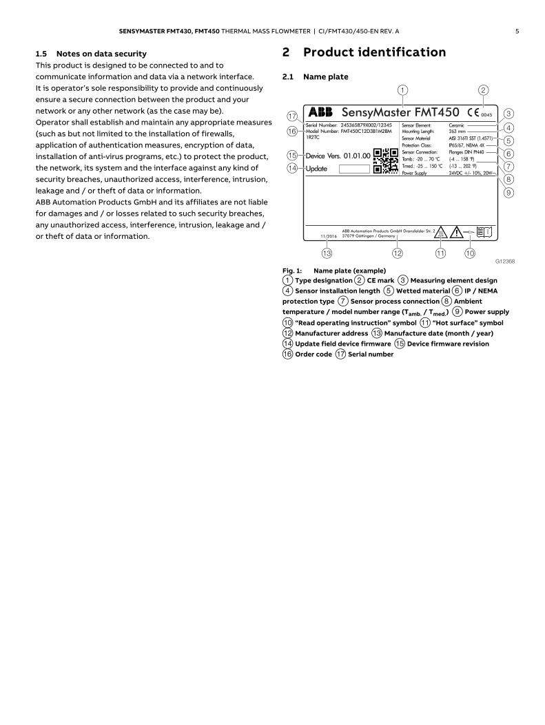
Fig. 1: Name plate (example) 1 Type designation 2 CE mark 3 Measuring element design 4 Sensor installation length 5 Wetted material 6 IP / NEMA protection type 7 Sensor process connection 8 Ambient temperature / model number range (Tamb. / Tmed.) 9 Power supply
j “Read operating instruction” symbol k “Hot surface” symbol l Manufacturer address m Manufacture date (month / year) n Update field device firmware o Device firmware revision p Order code q Serial number
6 SENSYMASTER FMT430, FMT450 THERMAL MASS FLOWMETER | CI/FMT430/450-EN REV. A
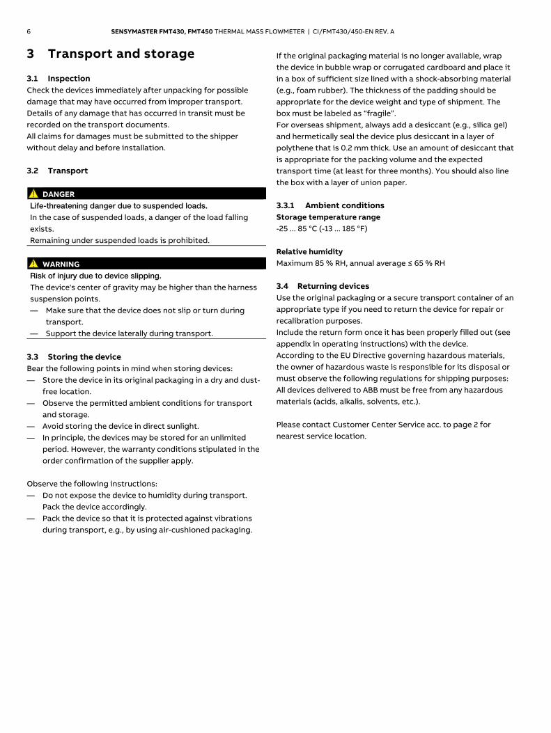
3 Transport and storage
3.1 Inspection Check the devices immediately after unpacking for possible damage that may have occurred from improper transport. Details of any damage that has occurred in transit must be recorded on the transport documents. All claims for damages must be submitted to the shipper without delay and before installation. 3.2 Transport
DANGER Life-threatening danger due to suspended loads. In the case of suspended loads, a danger of the load falling exists. Remaining under suspended loads is prohibited.
WARNING
Risk of injury due to device slipping. The device's center of gravity may be higher than the harness suspension points. — Make sure that the device does not slip or turn during
transport. — Support the device laterally during transport.
3.3 Storing the device Bear the following points in mind when storing devices: — Store the device in its original packaging in a dry and dust-
free location. — Observe the permitted ambient conditions for transport
and storage. — Avoid storing the device in direct sunlight. — In principle, the devices may be stored for an unlimited
period. However, the warranty conditions stipulated in the order confirmation of the supplier apply.
Observe the following instructions: — Do not expose the device to humidity during transport.
Pack the device accordingly. — Pack the device so that it is protected against vibrations
during transport, e.g., by using air-cushioned packaging.
If the original packaging material is no longer available, wrap the device in bubble wrap or corrugated cardboard and place it in a box of sufficient size lined with a shock-absorbing material (e.g., foam rubber). The thickness of the padding should be appropriate for the device weight and type of shipment. The box must be labeled as “fragile”. For overseas shipment, always add a desiccant (e.g., silica gel) and hermetically seal the device plus desiccant in a layer of polythene that is 0.2 mm thick. Use an amount of desiccant that is appropriate for the packing volume and the expected transport time (at least for three months). You should also line the box with a layer of union paper. 3.3.1 Ambient conditions Storage temperature range -25 ... 85 °C (-13 ... 185 °F) Relative humidity Maximum 85 % RH, annual average ≤ 65 % RH 3.4 Returning devices Use the original packaging or a secure transport container of an appropriate type if you need to return the device for repair or recalibration purposes. Include the return form once it has been properly filled out (see appendix in operating instructions) with the device. According to the EU Directive governing hazardous materials, the owner of hazardous waste is responsible for its disposal or must observe the following regulations for shipping purposes: All devices delivered to ABB must be free from any hazardous materials (acids, alkalis, solvents, etc.). Please contact Customer Center Service acc. to page 2 for nearest service location.
SENSYMASTER FMT430, FMT450 THERMAL MASS FLOWMETER | CI/FMT430/450-EN REV. A 7
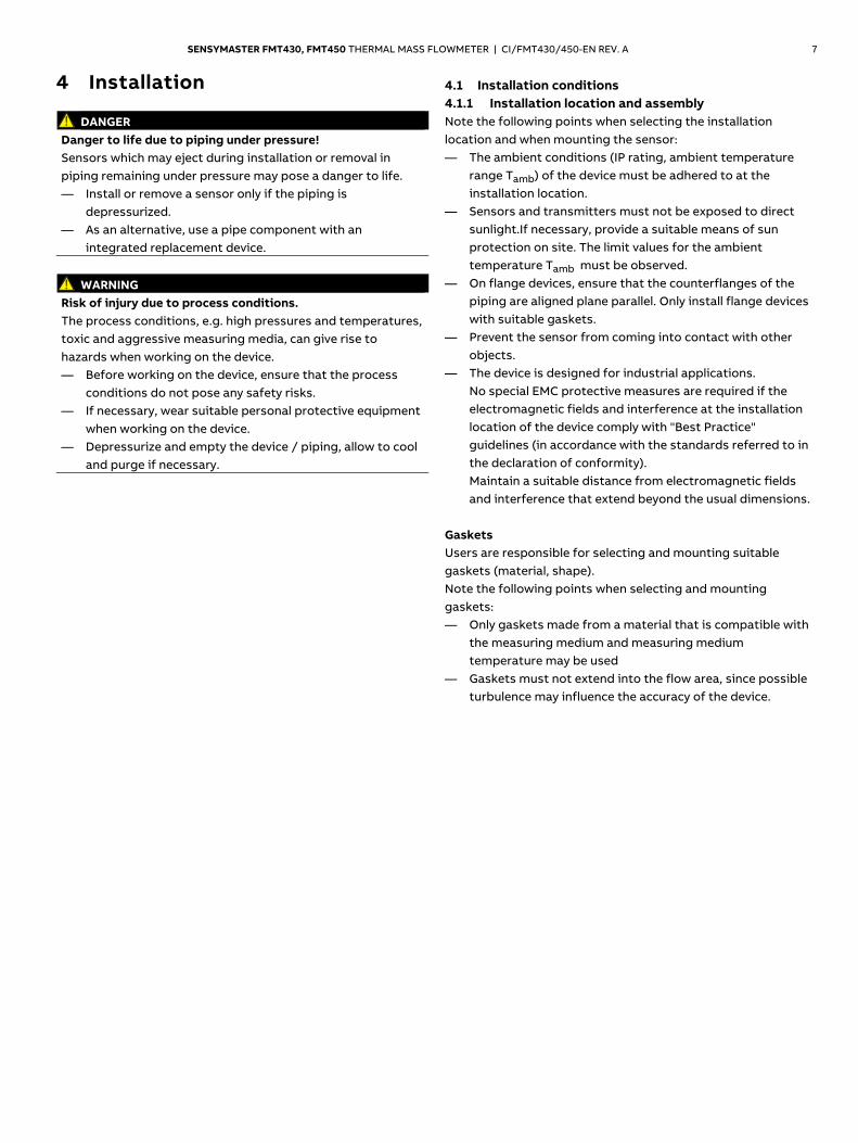
4 Installation
DANGER Danger to life due to piping under pressure! Sensors which may eject during installation or removal in piping remaining under pressure may pose a danger to life. — Install or remove a sensor only if the piping is
depressurized. — As an alternative, use a pipe component with an
integrated replacement device.
WARNING Risk of injury due to process conditions. The process conditions, e.g. high pressures and temperatures, toxic and aggressive measuring media, can give rise to hazards when working on the device. — Before working on the device, ensure that the process
conditions do not pose any safety risks. — If necessary, wear suitable personal protective equipment
when working on the device. — Depressurize and empty the device / piping, allow to cool
and purge if necessary.
4.1 Installation conditions 4.1.1 Installation location and assembly Note the following points when selecting the installation location and when mounting the sensor: — The ambient conditions (IP rating, ambient temperature
range Tamb) of the device must be adhered to at the installation location.
— Sensors and transmitters must not be exposed to direct sunlight.If necessary, provide a suitable means of sun protection on site. The limit values for the ambient temperature Tamb must be observed.
— On flange devices, ensure that the counterflanges of the piping are aligned plane parallel. Only install flange devices with suitable gaskets.
— Prevent the sensor from coming into contact with other objects.
— The device is designed for industrial applications. No special EMC protective measures are required if the electromagnetic fields and interference at the installation location of the device comply with "Best Practice" guidelines (in accordance with the standards referred to in the declaration of conformity). Maintain a suitable distance from electromagnetic fields and interference that extend beyond the usual dimensions.
Gaskets Users are responsible for selecting and mounting suitable gaskets (material, shape). Note the following points when selecting and mounting gaskets: — Only gaskets made from a material that is compatible with
the measuring medium and measuring medium temperature may be used
— Gaskets must not extend into the flow area, since possible turbulence may influence the accuracy of the device.
8 SENSYMASTER FMT430, FMT450 THERMAL MASS FLOWMETER | CI/FMT430/450-EN REV. A
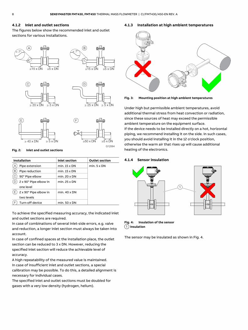
4.1.2 Inlet and outlet sections The figures below show the recommended inlet and outlet sections for various installations.
Fig. 2: Inlet and outlet sections
Installation Inlet section Outlet section
A Pipe extension min. 15 x DN min. 5 x DN
B Pipe reduction min. 15 x DN
C 90° Pipe elbow min. 20 x DN
D 2 x 90° Pipe elbow in
one level
min. 25 x DN
E 2 x 90° Pipe elbow in
two levels
min. 40 x DN
F Turn-off device min. 50 x DN
To achieve the specified measuring accuracy, the indicated inlet and outlet sections are required. In case of combinations of several inlet-side errors, e.g. valve and reduction, a longer inlet section must always be taken into account. In case of confined spaces at the installation place, the outlet section can be reduced to 3 x DN. However, reducing the specified inlet section will reduce the achievable level of accuracy. A high repeatability of the measured value is maintained. In case of insufficient inlet and outlet sections, a special calibration may be possible. To do this, a detailed alignment is necessary for individual cases. The specified inlet and outlet sections must be doubled for gases with a very low density (hydrogen, helium).
4.1.3 Installation at high ambient temperatures
G10858
��
Fig. 3: Mounting position at high ambient temperatures
Under high but permissible ambient temperatures, avoid additional thermal stress from heat convection or radiation, since these sources of heat may exceed the permissible ambient temperature on the equipment surface. If the device needs to be installed directly on a hot, horizontal piping, we recommend installing it on the side. In such cases, you should avoid installing it in the 12 o'clock position, otherwise the warm air that rises up will cause additional heating of the electronics. 4.1.4 Sensor insulation
G12338
1
Fig. 4: Insulation of the sensor 1 Insulation
The sensor may be insulated as shown in Fig. 4.
G12064
A B
C D
≥15 x DN ≥5 x DN ≥15 x DN ≥5 x DN
≥ 20 x DN ≥ 5 x DN ≥ 25 x DN ≥ 5 x DN
≥ 40 x DN ≥ 5 x DN ≥50 x DN ≥5 x DN
E F
< 7° < 7°
SENSYMASTER FMT430, FMT450 THERMAL MASS FLOWMETER | CI/FMT430/450-EN REV. A 9
4.2 Environmental conditions 4.2.1 Ambient temperature — Standard: -20 … 70 °C (-4 … 158 °F) — Extended TA9: -40 ... 70 °C (-40 ... 158 °F) — Extended TA6: -50 ... 70 °C (-58 ... 158 °F) Relative humidity Maximum 85 % RH, annual average ≤ 65 % RH IP rating In accordance with EN 60529: IP 65 / IP 67 4.2.2 NEMA rating NEMA 4X 4.3 Process conditions 4.3.1 Measuring medium temperature Devices with ceramic element and flange connection — Standard: -25 … 150 °C (-13 … 302 °F) — Extended (optional, only FMTx50):
-25 ... 300 °C (-13 ... 572 °F) The approved measuring medium temperature Tmedium also depends on the selected sensor process connection and the design of the pipe components. The following temperature specifications apply: Sensor connection Tmedium
Threaded connection DIN 11851 -40 ... 140 °C (-40 ... 284 °F)
Clamp ring fitting -25 ... 140 °C (-13 ... 284 °F)
Pipe components with ball valve Maximum 150 °C (302 °F)
Integrated hot tap fitting See the chapter titled ‘Material
loads for process connections’ on
page 10
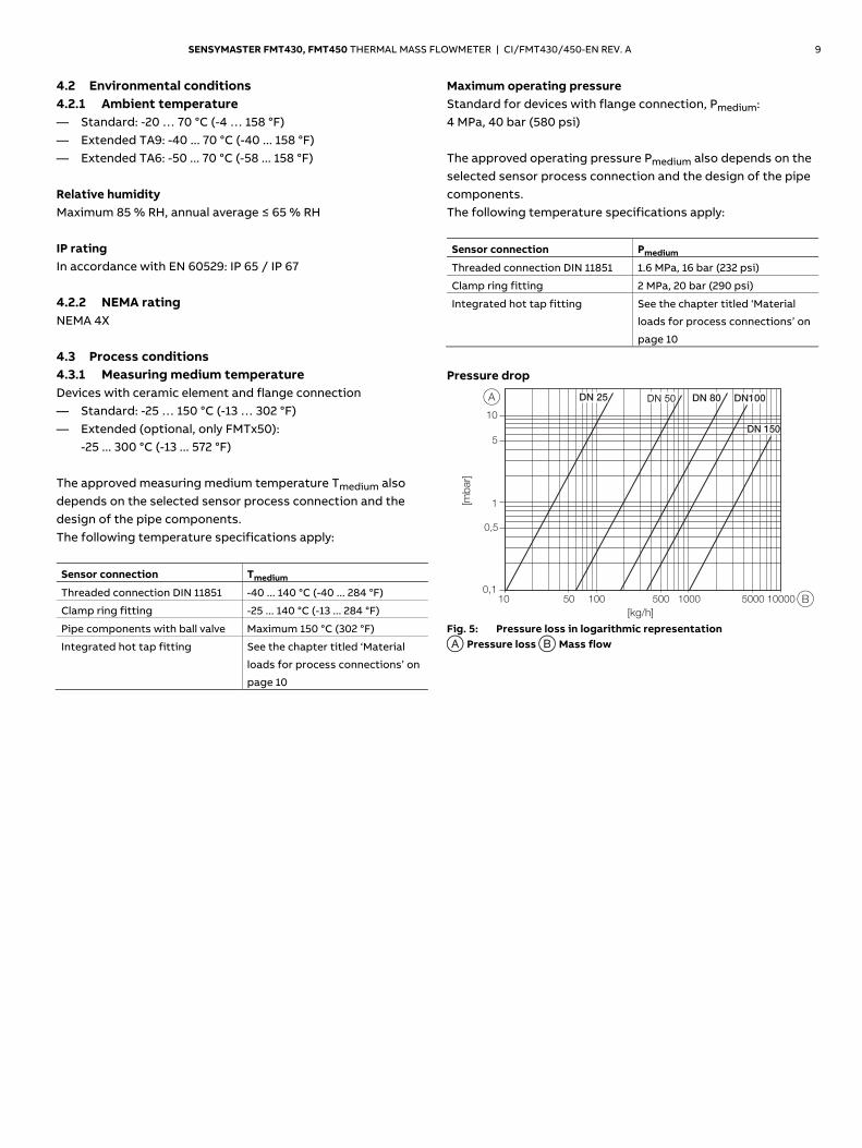
Maximum operating pressure Standard for devices with flange connection, Pmedium: 4 MPa, 40 bar (580 psi) The approved operating pressure Pmedium also depends on the selected sensor process connection and the design of the pipe components. The following temperature specifications apply: Sensor connection Pmedium
Threaded connection DIN 11851 1.6 MPa, 16 bar (232 psi)
Clamp ring fitting 2 MPa, 20 bar (290 psi)
Integrated hot tap fitting See the chapter titled ‘Material
loads for process connections’ on
page 10
Pressure drop
G10796
10 50 100 500 1000 5000 10000
10
5
0,5
0,1
1
DN 50 DN 80 DN100
DN 150
DN 25
[mb
ar]
[kg/h]
A
B
Fig. 5: Pressure loss in logarithmic representation A Pressure loss B Mass flow
10 SENSYMASTER FMT430, FMT450 THERMAL MASS FLOWMETER | CI/FMT430/450-EN REV. A
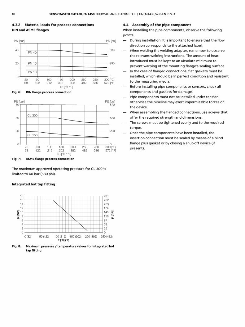
4.3.2 Material loads for process connections DIN and ASME flanges
G12340TS [°C /°F]
20 50 100 150 200 250 280 300 [°C]
40
20
0
PN 40580
290
0
68 122 212 302 392 482 536 572 [°F]
PS [psi]PS [bar]
PN 16
PN 10
Fig. 6: DIN flange process connection
G12341TS [°C / °F]
20 50 100 150 200 250 280 300 [°C]
PS [bar]60
40
20
0
CL 300
CL 150
870
580
290
0
68 122 212 302 392 482 536 572 [°F]
PS [psi]
Fig. 7: ASME flange process connection
The maximum approved operating pressure for CL 300 is limited to 40 bar (580 psi). Integrated hot tap fitting
G10815
0
2
4
6
8
10
12
14
16
18
0 (32) 50 (122) 100 (212) 150 (302) 200 (392) 250 (482)
T [°C] (°F)
0
29
58
87
116
145
174
203
232
261
p [
psi]
p [
bar]
Fig. 8: Maximum pressure / temperature values for integrated hot
tap fitting
4.4 Assembly of the pipe component When installing the pipe components, observe the following points: — During installation, it is important to ensure that the flow
direction corresponds to the attached label. — When welding the welding adapter, remember to observe
the relevant welding instructions. The amount of heat introduced must be kept to an absolute minimum to prevent warping of the mounting flange's sealing surface.
— In the case of flanged connections, flat gaskets must be installed, which should be in perfect condition and resistant to the measuring media.
— Before installing pipe components or sensors, check all components and gaskets for damage.
— Pipe components must not be installed under tension, otherwise the pipeline may exert impermissible forces on the device.
— When assembling the flanged connections, use screws that offer the required strength and dimensions.
— The screws must be tightened evenly and to the required torque.
— Once the pipe components have been installed, the insertion connection must be sealed by means of a blind flange plus gasket or by closing a shut-off device (if present).
SENSYMASTER FMT430, FMT450 THERMAL MASS FLOWMETER | CI/FMT430/450-EN REV. A 11
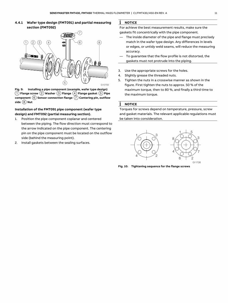
4.4.1 Wafer type design (FMT091) and partial measuring section (FMT092)
G10793
1 2 3 4 6
7
5
8
Fig. 9: Installing a pipe component (example, wafer type design) 1 Flange screw 2 Washer 3 Flange 4 Flange gasket 5 Pipe component 6 Sensor connection flange 7 Centering pin, outflow side 8 Nut
Installation of the FMT091 pipe component (wafer type design) and FMT092 (partial measuring section). 1. Position the pipe component coplanar and centered
between the piping. The flow direction must correspond to the arrow indicated on the pipe component. The centering pin on the pipe component must be located on the outflow side (behind the measuring point).
2. Install gaskets between the sealing surfaces.
NOTICE For achieve the best measurement results, make sure the gaskets fit concentrically with the pipe component. — The inside diameter of the pipe and flange must precisely
match in the wafer type design. Any differences in levels or edges, or untidy weld seams, will reduce the measuring accuracy.
— To guarantee that the flow profile is not distorted, the gaskets must not protrude into the piping.
3. Use the appropriate screws for the holes. 4. Slightly grease the threaded nuts. 5. Tighten the nuts in a crosswise manner as shown in the
figure. First tighten the nuts to approx. 50 % of the maximum torque, then to 80 %, and finally a third time to the maximum torque.
NOTICE
Torques for screws depend on temperature, pressure, screw and gasket materials. The relevant applicable regulations must be taken into consideration.
G11726
1
2
7
8
5
3
4
6
1
2
3
4
Fig. 10: Tightening sequence for the flange screws
12 SENSYMASTER FMT430, FMT450 THERMAL MASS FLOWMETER | CI/FMT430/450-EN REV. A
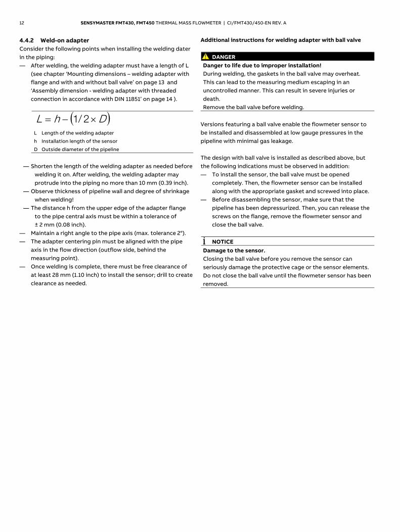
4.4.2 Weld-on adapter Consider the following points when installing the welding dater in the piping: — After welding, the welding adapter must have a length of L
(see chapter ‘Mounting dimensions – welding adapter with flange and with and without ball valve’ on page 13 and ‘Assembly dimension - welding adapter with threaded connection in accordance with DIN 11851’ on page 14 ).
DhL 2/1
L Length of the welding adapter
h Installation length of the sensor
D Outside diameter of the pipeline
— Shorten the length of the welding adapter as needed before
welding it on. After welding, the welding adapter may protrude into the piping no more than 10 mm (0.39 inch).
— Observe thickness of pipeline wall and degree of shrinkage when welding!
— The distance h from the upper edge of the adapter flange to the pipe central axis must be within a tolerance of ± 2 mm (0.08 inch).
— Maintain a right angle to the pipe axis (max. tolerance 2°). — The adapter centering pin must be aligned with the pipe
axis in the flow direction (outflow side, behind the measuring point).
— Once welding is complete, there must be free clearance of at least 28 mm (1.10 inch) to install the sensor; drill to create clearance as needed.
Additional instructions for welding adapter with ball valve
DANGER Danger to life due to improper installation! During welding, the gaskets in the ball valve may overheat. This can lead to the measuring medium escaping in an uncontrolled manner. This can result in severe injuries or death. Remove the ball valve before welding.
Versions featuring a ball valve enable the flowmeter sensor to be installed and disassembled at low gauge pressures in the pipeline with minimal gas leakage. The design with ball valve is installed as described above, but the following indications must be observed in addition: — To install the sensor, the ball valve must be opened
completely. Then, the flowmeter sensor can be installed along with the appropriate gasket and screwed into place.
— Before disassembling the sensor, make sure that the pipeline has been depressurized. Then, you can release the screws on the flange, remove the flowmeter sensor and close the ball valve.
NOTICE
Damage to the sensor. Closing the ball valve before you remove the sensor can seriously damage the protective cage or the sensor elements. Do not close the ball valve until the flowmeter sensor has been removed.
Change from two to one column
SENSYMASTER FMT430, FMT450 THERMAL MASS FLOWMETER | CI/FMT430/450-EN REV. A 13
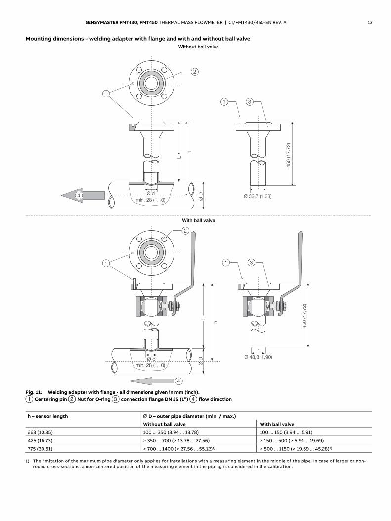
Mounting dimensions – welding adapter with flange and with and without ball valve Without ball valve
G10802
min. 28 (1.10)
h
L
Ø 33,7 (1.33)
450 (17.7
2)
Ø d
Ø D
1
2
1 3
4
With ball valve
G10803
h
LØ
D
2
Ø 48,3 (1,90)
450 (17,7
2)
4
1 3
min. 28 (1,10)Ø d
1
Fig. 11: Welding adapter with flange - all dimensions given in mm (inch). 1 Centering pin 2 Nut for O-ring 3 connection flange DN 25 (1”) 4 flow direction
h – sensor length Ø D – outer pipe diameter (min. / max.)
Without ball valve With ball valve
263 (10.35) 100 ... 350 (3.94 ... 13.78) 100 ... 150 (3.94 ... 5.91)
425 (16.73) > 350 ... 700 (> 13.78 ... 27.56) > 150 ... 500 (> 5.91 ... 19.69)
775 (30.51) > 700 ... 1400 (> 27.56 ... 55.12)1) > 500 ... 1150 (> 19.69 ... 45.28)1) 1) The limitation of the maximum pipe diameter only applies for installations with a measuring element in the middle of the pipe. In case of larger or non-
round cross-sections, a non-centered position of the measuring element in the piping is considered in the calibration.
14 SENSYMASTER FMT430, FMT450 THERMAL MASS FLOWMETER | CI/FMT430/450-EN REV. A
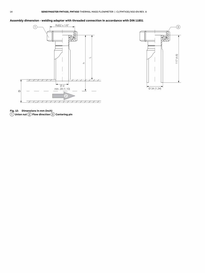
Assembly dimension - welding adapter with threaded connection in accordance with DIN 11851
Ø d
min. 28 (1.10)
D
h
Rd52 x 1/6”
L
G11022
Ø 34 (1,34)
117 (4.6
)
3
2
1
Fig. 12: Dimensions in mm (inch) 1 Union nut 2 Flow direction 3 Centering pin
Change from one to two columns
SENSYMASTER FMT430, FMT450 THERMAL MASS FLOWMETER | CI/FMT430/450-EN REV. A 15
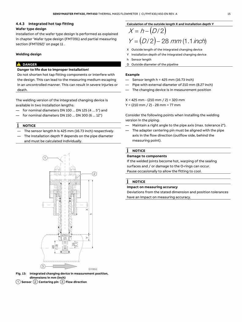
4.4.3 Integrated hot tap fitting Wafer type design Installation of the wafer type design is performed as explained in chapter ‘Wafer type design (FMT091) and partial measuring section (FMT092)’ on page 11 . Welding design
DANGER Danger to life due to improper installation! Do not shorten hot tap fitting components or interfere with the design. This can lead to the measuring medium escaping in an uncontrolled manner. This can result in severe injuries or death.
The welding version of the integrated changing device is available in two installation lengths: — for nominal diameters DN 100 ... DN 125 (4 ... 5") and — for nominal diameters DN 150 ... DN 300 (6 ... 12")
NOTICE — The sensor length h is 425 mm (16.73 inch) respectively. — The installation depth Y depends on the pipe diameter
and must be calculated individually.
G10852
X
h
Ø50
Y
28
48
(2)
(1,1
)
(1,9
)
1
2
3
Fig. 13: Integrated changing device in measurement position, dimensions in mm (inch)
1 Sensor 2 Centering pin 3 Flow direction
Calculation of the outside length X and installation depth Y
2/DhX
)1.1(282/ inchmmDY
X Outside length of the integrated changing device
Y Installation depth of the integrated changing device
h Sensor length
D Outside diameter of the pipeline
Example — Sensor length h = 425 mm (16.73 inch) — Pipe with external diameter of 210 mm (8.27 inch) — The changing device is in measurement position X = 425 mm - (210 mm / 2) = 320 mm Y = (210 mm / 2) - 28 mm = 77 mm Consider the following points when installing the welding version in the piping: — Maintain a right angle to the pipe axis (max. tolerance 2°). — The adapter centering pin must be aligned with the pipe
axis in the flow direction (outflow side, behind the measuring point).
NOTICE
Damage to components If the welded joints become hot, warping of the sealing surfaces and / or damage to the O-rings can occur. Pause occasionally to allow the fitting to cool.
NOTICE
Impact on measuring accuracy Deviations from the stated dimension and position tolerances have an impact on measuring accuracy.
16 SENSYMASTER FMT430, FMT450 THERMAL MASS FLOWMETER | CI/FMT430/450-EN REV. A
4.5 Installing the sensor When installing the sensor, observe the following points: — Installation in the pipe component or welding adapter is
only possible if the sensor data matches the measuring point specifications.
— The sensor may be sealed only by using the O-ring supplied in the scope of delivery. The O-ring must be placed in the designated groove on the sensor connection flange.
— The measuring elements may not be damaged when inserting the sensor into the pipe component.
— If you are using an integrated changing device, you must check that the changing device is in the disassembly position before releasing the mounting screws.
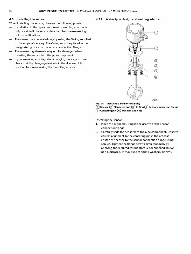
4.5.1 Wafer type design and welding adapter
Fig. 14: Installing a sensor (example) 1 Sensor 2 Flange screws 3 O-Ring 4 Sensor connection flange 5 Centering pin 6 Washers and nuts
Installing the sensor: 1. Place the supplied O-ring in the groove of the sensor
connection flange. 2. Carefully slide the sensor into the pipe component. Observe
correct alignment to the centering pin in the process 3. Fasten the sensor to the sensor connection flange using
screws. Tighten the flange screws simultaneously by applying the required torque (torque for supplied screws, non-lubricated, without use of spring washers: 87 Nm).
SENSYMASTER FMT430, FMT450 THERMAL MASS FLOWMETER | CI/FMT430/450-EN REV. A 17
4.5.2 Installation / Disassembly in connection with the changing device
DANGER
Danger to life due to piping under pressure! If the changing device is in the measurement position during disassembly of the sensor, this may pose a danger to life due to the possibility of the sensor being ejected. Disassemble the sensor only if the changing device is in the disassemble position.
DANGER
Danger to life due to leaking measuring medium! If the changing device is in the measurement position during disassembly of the sensor or gaskets in the changing device are damaged, leaking measuring medium may pose a danger to life. — Make sure that the changing device is in the disassemble
position. — If measuring medium should start to leak in spite of this,
immediately stop disassembly of the sensor and tighten the fastening screws.
— Drain and rinse the piping before disassembling the sensor, check and repair the changing device.
CAUTION
Risk of injury due to leaking measuring medium! When you disassemble the transmitter, small quantities of measuring medium may leak due to the nature of the design. Make sure that sufficient ventilation is ensured during disassembly of the sensor.
NOTICE
Damage to the changing device Using tools or other devices to operate the lock nut can damage the hot tap fitting. Only ever operate the lock nut manually.
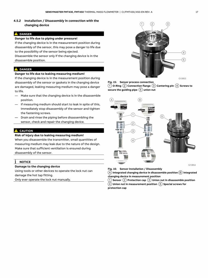
Fig. 15: Sensor process connection 1 O-Ring 2 Connection flange 3 Centering pin 4 Screws to secure the guiding pipe 5 union nut
Fig. 16: Sensor Installation / Disassembly A Integrated changing device in disassemble position B integrated changing device in measurement position 1 Sensor 2 Protection cap 3 Union nut in disassemble position 4 Union nut in measurement position 5 Special screws for protection cap
18 SENSYMASTER FMT430, FMT450 THERMAL MASS FLOWMETER | CI/FMT430/450-EN REV. A
Installation of the sensor during operation
NOTICE The changing device must be in the disassemble position before disassembling the sensor, the sensor process connection is sealed.
Installing the sensor: 1. Place the supplied O-ring in the groove of the sensor
connection flange. 2. Carefully slide the sensor into the changing device. Observe
correct alignment to the centering pin in the process. 3. Fasten the sensor to the sensor connection flange using
screws. Use the supplied M12 screws, as well as two extended special screws for this.
4. Place the protection caps onto the special screws and tighten using two nuts.
5. Twist the transmitter with the union nut into the measuring position. The lower edge of the union nut indicates the position of the sensor. Only when the measuring position is reached 50 - OPEN - MESSEN (the lower limit stop of the union nut) will the sensor be in the middle of the piping and precise values can be provided.
6. Carry out the electrical connection Disassembly of the sensor during operation Disassembly of the sensor: 1. Twist the transmitter with the union nut into the
disassemble position. The lower edge of the union nut indicates the position of the sensor. Only when the disassemble position is reached 0 - CLOSE - ZU (the upper limit stop of the union nut) will the sensor be in the disassemble position and the changing device is sealed off from the process.
2. Disconnect electrical connections. 3. Remove protection caps. 4. Remove flange screws. 5. Carefully pull the sensor out of the changing device (do not
tip to the side).
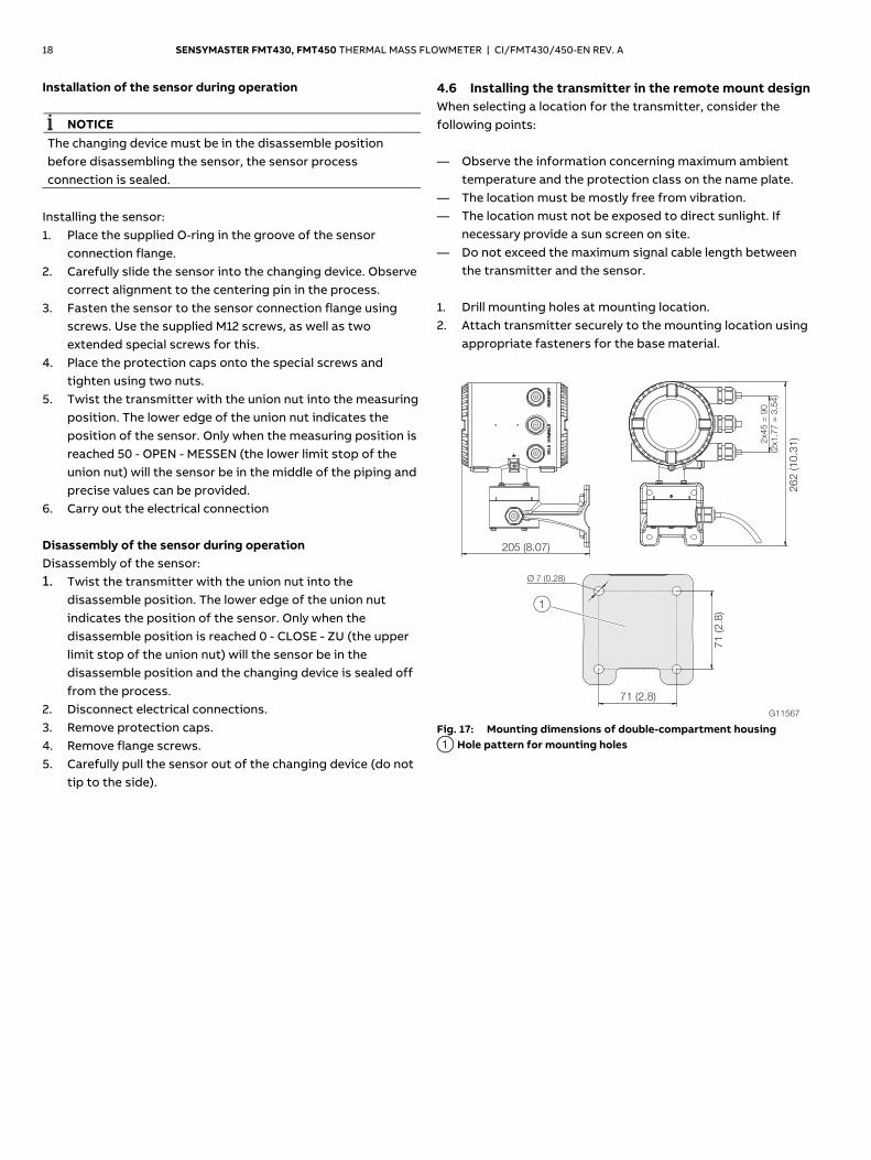
4.6 Installing the transmitter in the remote mount design When selecting a location for the transmitter, consider the following points: — Observe the information concerning maximum ambient
temperature and the protection class on the name plate. — The location must be mostly free from vibration. — The location must not be exposed to direct sunlight. If
necessary provide a sun screen on site. — Do not exceed the maximum signal cable length between
the transmitter and the sensor. 1. Drill mounting holes at mounting location. 2. Attach transmitter securely to the mounting location using
appropriate fasteners for the base material.
Fig. 17: Mounting dimensions of double-compartment housing 1 Hole pattern for mounting holes
G11567
205 (8.07)
2x4
5 =
90
(2x1
.77
= 3
.54
)
262 (10.3
1)
71 (2.8
)
71 (2.8)
Ø 7 (0.28)
1
SENSYMASTER FMT430, FMT450 THERMAL MASS FLOWMETER | CI/FMT430/450-EN REV. A 19
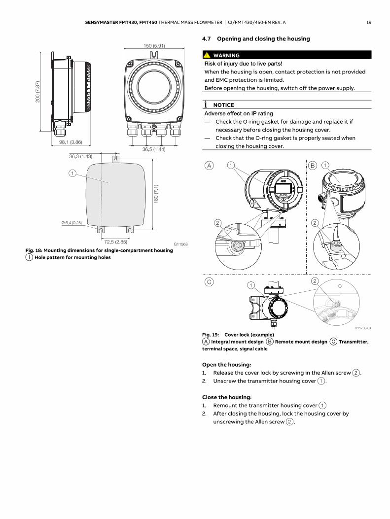
Fig. 18: Mounting dimensions for single-compartment housing 1 Hole pattern for mounting holes
4.7 Opening and closing the housing
WARNING Risk of injury due to live parts! When the housing is open, contact protection is not provided and EMC protection is limited. Before opening the housing, switch off the power supply.
NOTICE
Adverse effect on IP rating — Check the O-ring gasket for damage and replace it if
necessary before closing the housing cover. — Check that the O-ring gasket is properly seated when
closing the housing cover.
Fig. 19: Cover lock (example) A Integral mount design B Remote mount design C Transmitter, terminal space, signal cable
Open the housing: 1. Release the cover lock by screwing in the Allen screw 2. 2. Unscrew the transmitter housing cover a. Close the housing: 1. Remount the transmitter housing cover a 2. After closing the housing, lock the housing cover by
unscrewing the Allen screw 2.
G11568
98,1 (3.86)
20
0 (7
.87
)
36,5 (1.44)
150 (5.91)
1
18
0 (7
,1)
72,5 (2.85)
36,3 (1.43)
Ø 6,4 (0.25)
20 SENSYMASTER FMT430, FMT450 THERMAL MASS FLOWMETER | CI/FMT430/450-EN REV. A
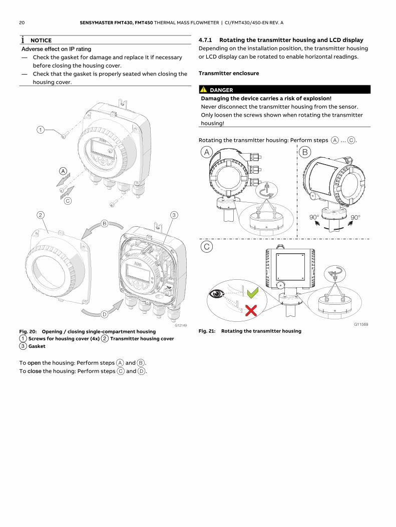
NOTICE Adverse effect on IP rating — Check the gasket for damage and replace it if necessary
before closing the housing cover. — Check that the gasket is properly seated when closing the
housing cover.
Fig. 20: Opening / closing single-compartment housing 1 Screws for housing cover (4x) 2 Transmitter housing cover 3 Gasket
To open the housing: Perform steps A and B. To close the housing: Perform steps C and D.
4.7.1 Rotating the transmitter housing and LCD display Depending on the installation position, the transmitter housing or LCD display can be rotated to enable horizontal readings. Transmitter enclosure
DANGER Damaging the device carries a risk of explosion! Never disconnect the transmitter housing from the sensor. Only loosen the screws shown when rotating the transmitter housing!
Rotating the transmitter housing: Perform steps A … C.
G11569
A B
90°90°
C
Fig. 21: Rotating the transmitter housing
SENSYMASTER FMT430, FMT450 THERMAL MASS FLOWMETER | CI/FMT430/450-EN REV. A 21
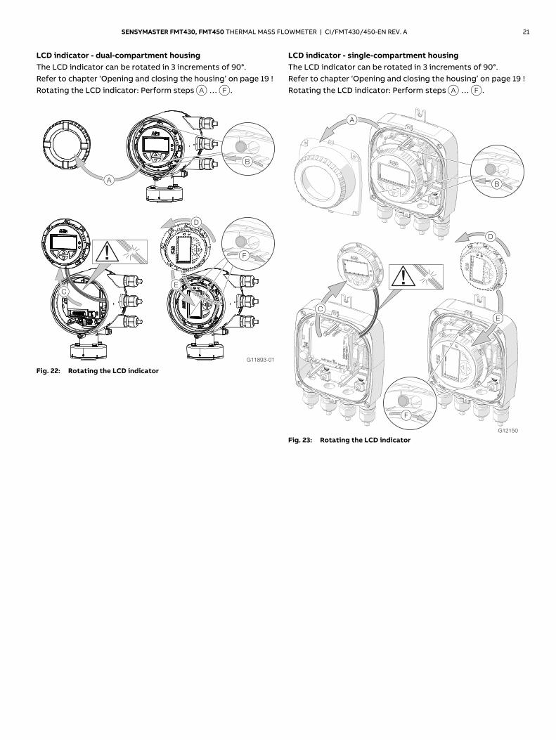
LCD indicator - dual-compartment housing The LCD indicator can be rotated in 3 increments of 90°. Refer to chapter ‘Opening and closing the housing’ on page 19 ! Rotating the LCD indicator: Perform steps A … F.
Fig. 22: Rotating the LCD indicator
LCD indicator - single-compartment housing The LCD indicator can be rotated in 3 increments of 90°. Refer to chapter ‘Opening and closing the housing’ on page 19 ! Rotating the LCD indicator: Perform steps A … F.
Fig. 23: Rotating the LCD indicator
22 SENSYMASTER FMT430, FMT450 THERMAL MASS FLOWMETER | CI/FMT430/450-EN REV. A
4.8 Installing the plug-in cards
WARNING Loss of Ex-approval! Loss of Ex approval due to retrofitting of plug-in cards on devices for use in potentially explosive atmospheres. — Devices for use in potentially explosive atmospheres must
not be retrofitted with plug-in cards. — If devices are to be used in potentially explosive
atmospheres, the required plug-in cards must be specified when the order is placed.
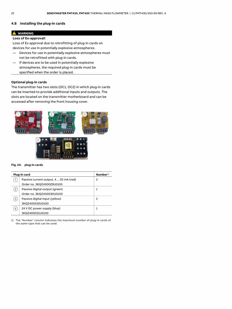
Optional plug-in cards The transmitter has two slots (OC1, OC2) in which plug-in cards can be inserted to provide additional inputs and outputs. The slots are located on the transmitter motherboard and can be accessed after removing the front housing cover.
G11896
1 2 3
4
Fig. 24: plug-in cards
Plug-in card Number1)
1 Passive current output, 4 ... 20 mA (red)
Order no. 3KQZ400029U0100
2
2 Passive digital output (green)
Order no. 3KQZ400030U0100
1
3 Passive digital input (yellow)
3KQZ400032U0100
2
4 24 V DC power supply (blue)
3KQZ400031U0100
1
1) The "Number" column indicates the maximum number of plug-in cards of
the same type that can be used.
Change from two to one column
SENSYMASTER FMT430, FMT450 THERMAL MASS FLOWMETER | CI/FMT430/450-EN REV. A 23
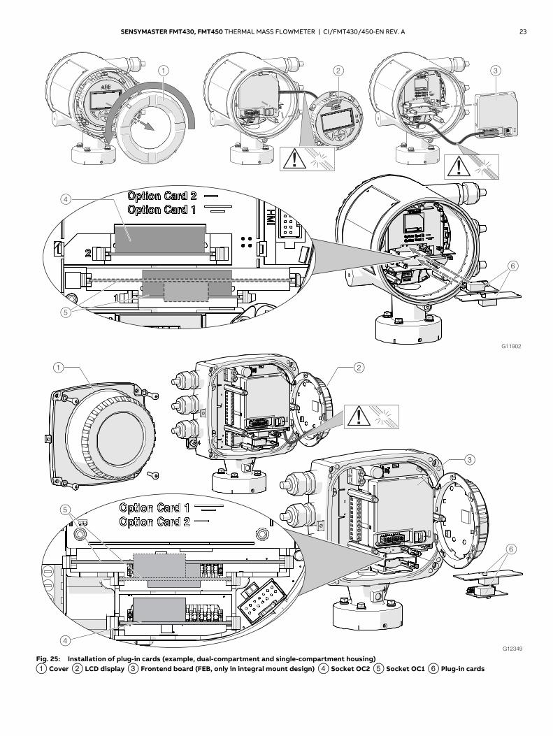
Fig. 25: Installation of plug-in cards (example, dual-compartment and single-compartment housing) 1 Cover 2 LCD display 3 Frontend board (FEB, only in integral mount design) 4 Socket OC2 5 Socket OC1 6 Plug-in cards
24 SENSYMASTER FMT430, FMT450 THERMAL MASS FLOWMETER | CI/FMT430/450-EN REV. A
Change from one to two columns
WARNING Risk of injury due to live parts! When the housing is open, contact protection is not provided and EMC protection is limited. Before opening the housing, switch off the power supply.
NOTICE
Damage to components! The electronic components of the printed circuit board can be damaged by static electricity (observe ESD guidelines). Make sure that the static electricity in your body is discharged before touching electronic components.
1. Switch off the power supply. 2. Unscrew / remove the cover. 3. Remove the LCD indicator. Ensure that the cable harness is
not damaged. Insert the LCD display into the bracket (only for single-
compartment housings) 4. Remove frontend board (only in integral mount design and
dual-compartment housing). Ensure that the cable harness is not damaged.
5. Insert the plug-in card in the corresponding slot and engage. Ensure that the contacts are aligned correctly.
6. Attach the frontend board, insert the LCD display and screw on / replace the cover.
7. Connect outputs V1 / V2 and V3 / V4 in accordance with chapter ‘Electrical connections’ on page 24 .
8. After powering up the power supply, configure the plug-in card functions.
4.9 Electrical connections
WARNING Risk of injury due to live parts. Improper work on the electrical connections can result in electric shock. — Connect the device only with the power supply switched
off. — Observe the applicable standards and regulations for the
electrical connection. The electrical connection may only be established by authorized specialist personnel and in accordance with the connection diagrams. The electrical connection information in this manual must be observed; otherwise, the IP rating may be adversely affected. Ground the measurement system according to requirements. 4.9.1 Connecting the power supply
NOTICE — Observe the power supply limit values in accordance with
the information on the name plate. — Observe the voltage drop for large cable lengths and small
conductor cross-sections. The voltage at the terminals of the device may not fall below the minimum value required in accordance with the information on the name plate.
The power supply is connected to terminal L (phase), N (neutral), or 1+, 2-, and PE, as stated on the name plate. A circuit breaker with a maximum rated current of 16 A must be installed in the power supply line of the transmitter. The wire cross-sectional area of the power supply cable and the circuit breaker used must comply with VDE 0100 and must be dimensioned in accordance with the current consumption of the flowmeter measuring system. The cables must comply with IEC 227 and/or IEC 245. The circuit breaker should be located near the transmitter and marked as being associated with the device. Connect the transmitter and sensor to functional earth.
SENSYMASTER FMT430, FMT450 THERMAL MASS FLOWMETER | CI/FMT430/450-EN REV. A 25
4.9.2 Cable entries The electrical connection is made via cable entries with a 1/2" NPT or M20 x 1.5 thread. Devices with an M20 x 1.5 or 1/2" NPT thread are supplied with protective plugs. The black protective plugs in the cable glands are intended to provide protection during transport. Any unused cable entries must be sealed before commissioning using sealing plugs in accordance with the applicable local standards. — Observe the maximum torque of 4.5 Nm (3.3 ft lb) when
tightening the M20 cable gland. — Make sure that the outer dimension of cable used, fits the
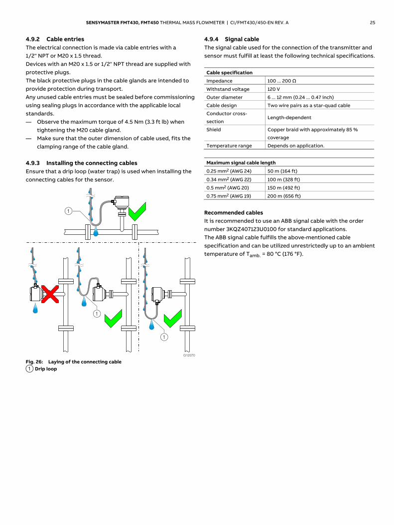
clamping range of the cable gland. 4.9.3 Installing the connecting cables Ensure that a drip loop (water trap) is used when installing the connecting cables for the sensor.
G12070
1
1
1
Fig. 26: Laying of the connecting cable 1 Drip loop
4.9.4 Signal cable The signal cable used for the connection of the transmitter and sensor must fulfill at least the following technical specifications. Cable specification
Impedance 100 ... 200 Ω
Withstand voltage 120 V
Outer diameter 6 ... 12 mm (0.24 ... 0.47 inch)
Cable design Two wire pairs as a star-quad cable
Conductor cross-
section Length-dependent
Shield Copper braid with approximately 85 %
coverage
Temperature range Depends on application.
Maximum signal cable length
0.25 mm2 (AWG 24) 50 m (164 ft)
0.34 mm2 (AWG 22) 100 m (328 ft)
0.5 mm2 (AWG 20) 150 m (492 ft)
0.75 mm2 (AWG 19) 200 m (656 ft)
Recommended cables It is recommended to use an ABB signal cable with the order number 3KQZ407123U0100 for standard applications. The ABB signal cable fulfills the above-mentioned cable specification and can be utilized unrestrictedly up to an ambient temperature of Tamb. = 80 °C (176 °F).
Change from two to one column
26 SENSYMASTER FMT430, FMT450 THERMAL MASS FLOWMETER | CI/FMT430/450-EN REV. A
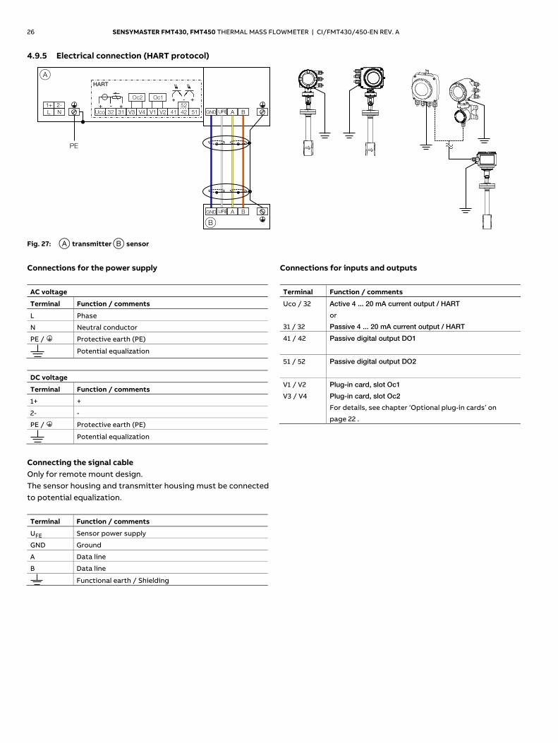
4.9.5 Electrical connection (HART protocol)
G12069
A
L N
1+ 2-
PE
B
GND A B
+ -
+ - +
HART
Uco 32 31 V3 V4 V1 V2 41
52
42 51
+Oc2 Oc1
A B
UFE
GND UFE
Fig. 27: A transmitter B sensor
Change from one to two columns
Connections for the power supply AC voltage
Terminal Function / comments
L Phase
N Neutral conductor
PE / Protective earth (PE)
Potential equalization
DC voltage
Terminal Function / comments
1+ +
2- -
PE / Protective earth (PE)
Potential equalization
Connecting the signal cable Only for remote mount design. The sensor housing and transmitter housing must be connected to potential equalization. Terminal Function / comments
UFE Sensor power supply
GND Ground
A Data line
B Data line
Functional earth / Shielding
Connections for inputs and outputs Terminal Function / comments
Uco / 32
31 / 32
Active 4 ... 20 mA current output / HART
or
Passive 4 ... 20 mA current output / HART
41 / 42 Passive digital output DO1
51 / 52 Passive digital output DO2
V1 / V2
V3 / V4
Plug-in card, slot Oc1
Plug-in card, slot Oc2
For details, see chapter ‘Optional plug-in cards’ on
page 22 .
SENSYMASTER FMT430, FMT450 THERMAL MASS FLOWMETER | CI/FMT430/450-EN REV. A 27
4.10 Electrical data for inputs and outputs Power supply AC voltage
Terminals L / N
Operating voltage 100 ... 240 V AC, (-15 % / +10 %), 47 … 64 Hz
Power consumption Smax: < 20 VA
Power-up current 18.4 A, t < 3 ms
DC voltage
Terminals 1+ / 2-
Operating voltage 24 V DC ± 20 %
Ripple < 5 %
Power Consumption Pmax: < 20 W
Power-up current 21 A, t < 10 ms
HART communication A HART DTM in accordance with FDT1.2 standards is available. HART protocol based Integrations in other Tools or systems (e.g., Emerson AMS/Siemens PCS7) are available on request. The DTM, the DD and EDD is available for download from www.abb.com/flow. HART output
Terminals Active: Uco / 32
Passive: 31 / 32
Protocol HART 7.1
Transmission FSK modulation on current output 4 … 20 mA in
accordance with Bell 202 standard
Baud rate 1200 baud
Signal amplitude Maximum 1.2 mAss
Current output
load
Minimum 250 Ω
Cable 0,25 mm2 (AWG 24), twisted
Maximum cable
length
1200 m (3937 ft)
NOTICE
The HART protocol is not secure, as such the intended application should be assessed to ensure that these protocols are suitable before implementation.
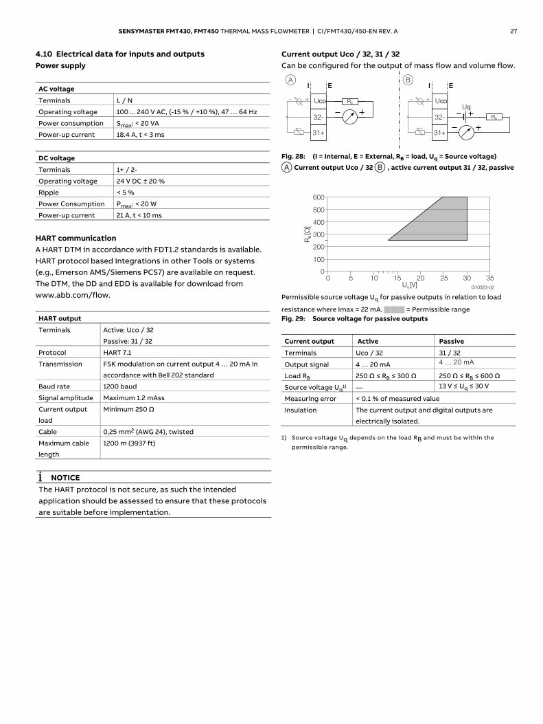
Current output Uco / 32, 31 / 32 Can be configured for the output of mass flow and volume flow.
G11596-02
+-
A BI E
32-
Uco
32-
I E
31+
RB
RB
Uq
31+
Uco+-
Fig. 28: (I = Internal, E = External, RB = load, Uq = Source voltage)
A Current output Uco / 32 B , active current output 31 / 32, passive
Permissible source voltage Uq for passive outputs in relation to load
resistance where Imax = 22 mA. = Permissible range Fig. 29: Source voltage for passive outputs
Current output Active Passive
Terminals Uco / 32 31 / 32
Output signal 4 … 20 mA 4 ... 20 mA
Load RB 250 Ω ≤ RB ≤ 300 Ω 250 Ω ≤ RB ≤ 600 Ω
Source voltage Uq1) — 13 V ≤ Uq ≤ 30 V
Measuring error < 0.1 % of measured value
Insulation The current output and digital outputs are
electrically isolated. 1) Source voltage Uq depends on the load RB and must be within the
permissible range.
G10323-02
00
100
200
300
400
500
600
5 10 15 20 25 30 35
RB[Ω
]
U [V]q
28 SENSYMASTER FMT430, FMT450 THERMAL MASS FLOWMETER | CI/FMT430/450-EN REV. A
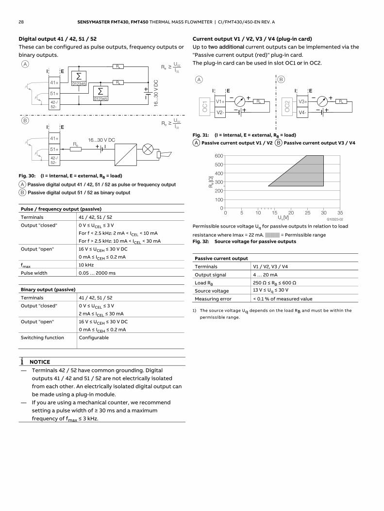
Digital output 41 / 42, 51 / 52 These can be configured as pulse outputs, frequency outputs or binary outputs.
G11597-02
A
16...30 V DC
BRB
UCE
ICE
RB
UCE
ICE
41+
51+
I E
42-/
52-
41+
51+
I E
42-/
52-
RB
RB
012345
16
...3
0 V
DC
012345
RB
Fig. 30: (I = internal, E = external, RB = load)
A Passive digital output 41 / 42, 51 / 52 as pulse or frequency output
B Passive digital output 51 / 52 as binary output
Pulse / frequency output (passive)
Terminals 41 / 42, 51 / 52
Output "closed" 0 V ≤ UCEL ≤ 3 V
For f < 2.5 kHz: 2 mA < ICEL < 10 mA
For f > 2.5 kHz: 10 mA < ICEL < 30 mA
Output "open" 16 V ≤ UCEH ≤ 30 V DC
0 mA ≤ ICEH ≤ 0.2 mA
fmax 10 kHz
Pulse width 0.05 … 2000 ms
Binary output (passive)
Terminals 41 / 42, 51 / 52
Output "closed" 0 V ≤ UCEL ≤ 3 V
2 mA ≤ ICEL ≤ 30 mA
Output "open" 16 V ≤ UCEH ≤ 30 V DC
0 mA ≤ ICEH ≤ 0.2 mA
Switching function Configurable
NOTICE
— Terminals 42 / 52 have common grounding. Digital outputs 41 / 42 and 51 / 52 are not electrically isolated from each other. An electrically isolated digital output can be made using a plug-in module.
— If you are using a mechanical counter, we recommend setting a pulse width of ≥ 30 ms and a maximum frequency of fmax ≤ 3 kHz.
Current output V1 / V2, V3 / V4 (plug-in card) Up to two additional current outputs can be implemented via the "Passive current output (red)" plug-in card. The plug-in card can be used in slot OC1 or in OC2.
G11897-02
A B
V1+
I E
V2-
RB
OC
1 V3+
I E
V4-
RB
OC
2
Fig. 31: (I = internal, E = external, RB = load)
A Passive current output V1 / V2 B Passive current output V3 / V4
Permissible source voltage Uq for passive outputs in relation to load
resistance where Imax = 22 mA. = Permissible range Fig. 32: Source voltage for passive outputs
Passive current output
Terminals V1 / V2, V3 / V4
Output signal 4 … 20 mA
Load RB 250 Ω ≤ RB ≤ 600 Ω
Source voltage 13 V ≤ Uq ≤ 30 V
Measuring error < 0.1 % of measured value 1) The source voltage Uq depends on the load RB and must be within the
permissible range.
G10323-02
00
100
200
300
400
500
600
5 10 15 20 25 30 35R
B[Ω
]
U [V]q
SENSYMASTER FMT430, FMT450 THERMAL MASS FLOWMETER | CI/FMT430/450-EN REV. A 29
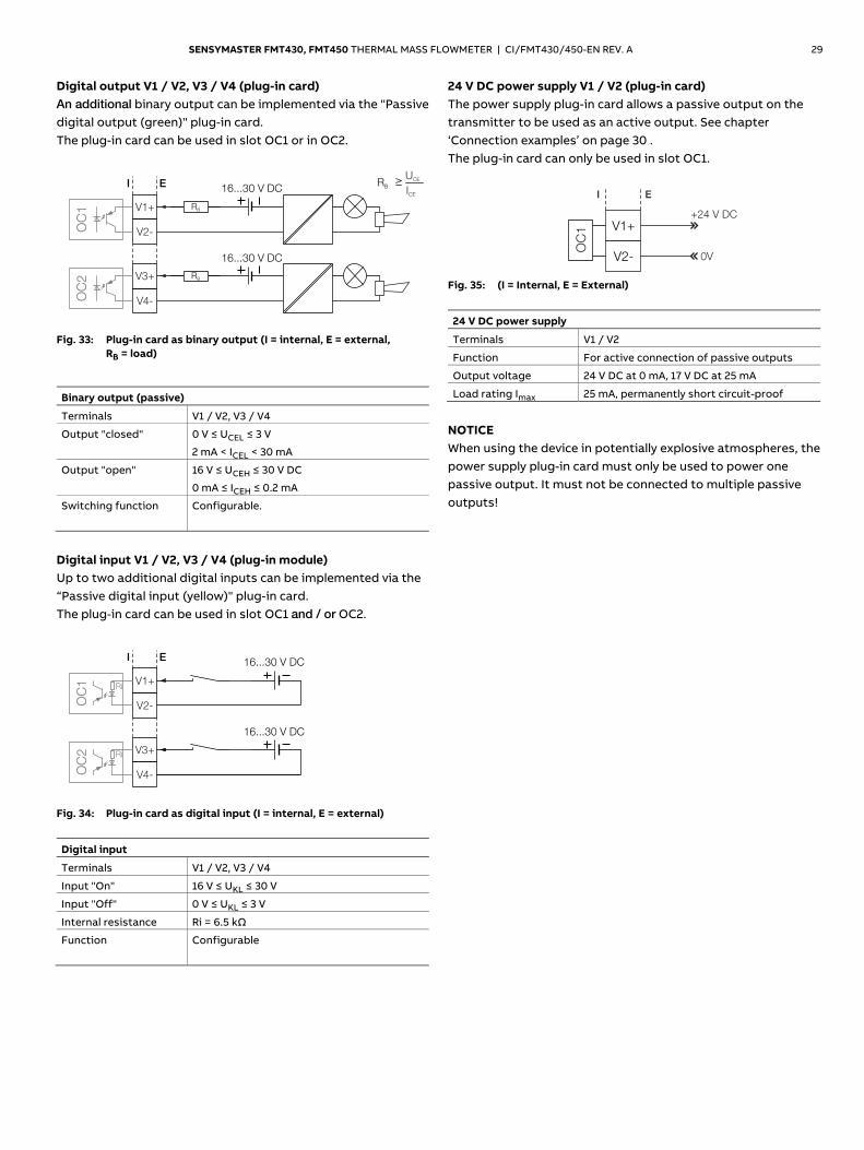
Digital output V1 / V2, V3 / V4 (plug-in card) An additional binary output can be implemented via the "Passive digital output (green)" plug-in card. The plug-in card can be used in slot OC1 or in OC2.
G11898-01
RB
UCE
ICE
16...30 V DC
V2-
V3+
I E
V1+
V4-
16...30 V DC
RB
RB
OC
2O
C1
Fig. 33: Plug-in card as binary output (I = internal, E = external,
RB = load)
Binary output (passive)
Terminals V1 / V2, V3 / V4
Output "closed" 0 V ≤ UCEL ≤ 3 V
2 mA < ICEL < 30 mA
Output "open" 16 V ≤ UCEH ≤ 30 V DC
0 mA ≤ ICEH ≤ 0.2 mA
Switching function Configurable.
Digital input V1 / V2, V3 / V4 (plug-in module) Up to two additional digital inputs can be implemented via the “Passive digital input (yellow)" plug-in card. The plug-in card can be used in slot OC1 and / or OC2.
G11598-01
16...30 V DC
V2-
V3+
I E
V1+
V4-
16...30 V DC
OC
2O
C1 Ri
Ri
Fig. 34: Plug-in card as digital input (I = internal, E = external)
Digital input
Terminals V1 / V2, V3 / V4
Input "On" 16 V ≤ UKL ≤ 30 V
Input "Off" 0 V ≤ UKL ≤ 3 V
Internal resistance Ri = 6.5 kΩ
Function Configurable
24 V DC power supply V1 / V2 (plug-in card) The power supply plug-in card allows a passive output on the transmitter to be used as an active output. See chapter ‘Connection examples’ on page 30 . The plug-in card can only be used in slot OC1.
G11739
V1+
I E
+24 V DC
0VV2-
OC
1
Fig. 35: (I = Internal, E = External)
24 V DC power supply
Terminals V1 / V2
Function For active connection of passive outputs
Output voltage 24 V DC at 0 mA, 17 V DC at 25 mA
Load rating Imax 25 mA, permanently short circuit-proof
NOTICE When using the device in potentially explosive atmospheres, the power supply plug-in card must only be used to power one passive output. It must not be connected to multiple passive outputs!
30 SENSYMASTER FMT430, FMT450 THERMAL MASS FLOWMETER | CI/FMT430/450-EN REV. A
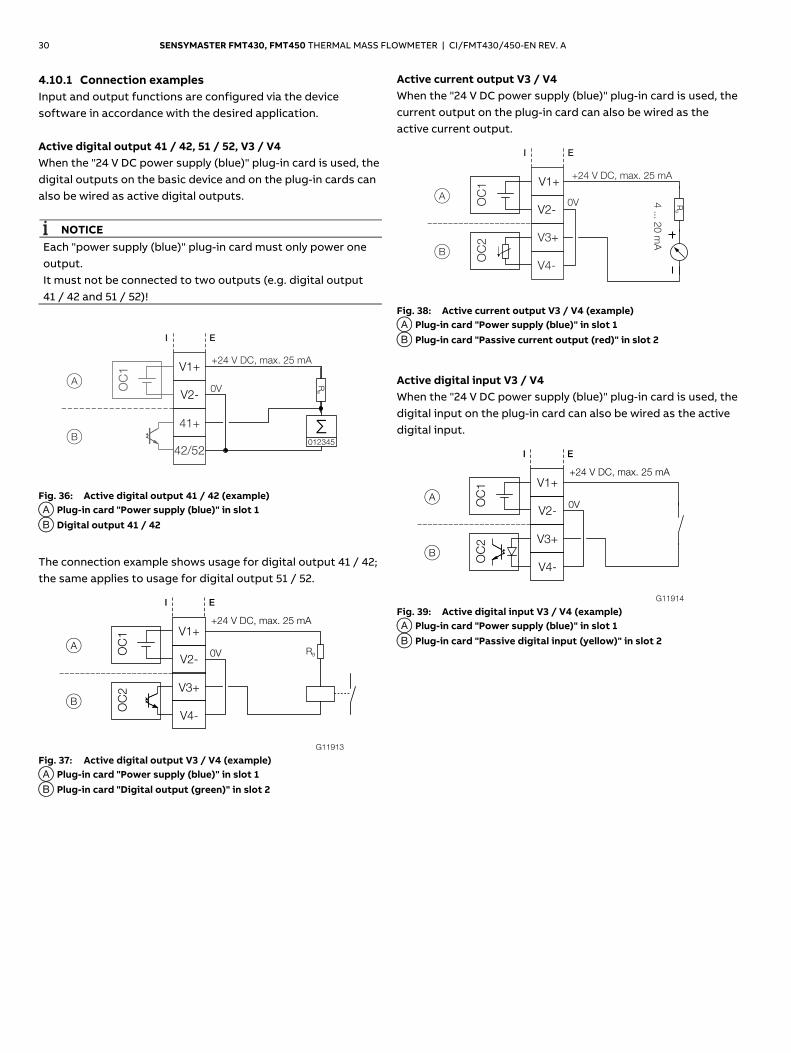
4.10.1 Connection examples Input and output functions are configured via the device software in accordance with the desired application. Active digital output 41 / 42, 51 / 52, V3 / V4 When the "24 V DC power supply (blue)" plug-in card is used, the digital outputs on the basic device and on the plug-in cards can also be wired as active digital outputs.
NOTICE Each "power supply (blue)" plug-in card must only power one output. It must not be connected to two outputs (e.g. digital output 41 / 42 and 51 / 52)!
G11744-01
AV2-
V1+
I E
+24 V , max. 25 mADC
0V
41+
42/52
B
OC
1
012345
RB
Fig. 36: Active digital output 41 / 42 (example) A Plug-in card "Power supply (blue)" in slot 1 B Digital output 41 / 42
The connection example shows usage for digital output 41 / 42; the same applies to usage for digital output 51 / 52.
Fig. 37: Active digital output V3 / V4 (example) A Plug-in card "Power supply (blue)" in slot 1 B Plug-in card "Digital output (green)" in slot 2
Active current output V3 / V4 When the "24 V DC power supply (blue)" plug-in card is used, the current output on the plug-in card can also be wired as the active current output.
G11742-01
AV2-
V1+
I E
+24 V , max. 25 mADC
0V 4 ... 2
0 m
AV3+
V4-
B
OC
1O
C2
RB
Fig. 38: Active current output V3 / V4 (example) A Plug-in card "Power supply (blue)" in slot 1 B Plug-in card "Passive current output (red)" in slot 2
Active digital input V3 / V4 When the "24 V DC power supply (blue)" plug-in card is used, the digital input on the plug-in card can also be wired as the active digital input.
Fig. 39: Active digital input V3 / V4 (example) A Plug-in card "Power supply (blue)" in slot 1 B Plug-in card "Passive digital input (yellow)" in slot 2
Change from two to one column
G11913
AV2-
V1+
I E
+24 V DC, max. 25 mA
0V
B
RB
V4-
V3+
OC
2O
C1
G11914
AV2-
V1+
I E
+24 V DC, max. 25 mA
0V
BV4-
V3+
OC
2O
C1
SENSYMASTER FMT430, FMT450 THERMAL MASS FLOWMETER | CI/FMT430/450-EN REV. A 31
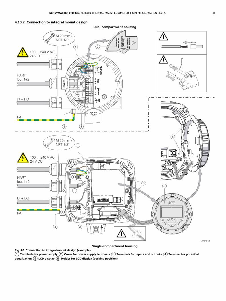
4.10.2 Connection to integral mount design Dual-compartment housing
Single-compartment housing
Fig. 40: Connection to integral mount design (example) 1 Terminals for power supply 2 Cover for power supply terminals 3 Terminals for inputs and outputs 4 Terminal for potential equalization 5 LCD display 6 Holder for LCD display (parking position) Change from one to two columns
32 SENSYMASTER FMT430, FMT450 THERMAL MASS FLOWMETER | CI/FMT430/450-EN REV. A
NOTICE If the O-ring gasket is seated incorrectly or damaged, this may have an adverse effect on the housing protection class. Follow the instructions in chapter ‘Opening and closing the housing’ on page 19 to open and close the housing safely.
Observe the following points when connecting to an electrical supply: — Lead the power supply cable into the housing through the
top cable entry. — Lead the cables for signal inputs and signal outputs into the
housing through the middle and, where necessary, bottom cable entries.
— Connect the cables in accordance with the electrical connection diagram. If present, connect the cable shielding to the earthing clamp provided.
— Use wire end ferrules when connecting. — After connecting the power supply to the dual-
compartment housing, terminal cover 2 must be installed.
— Close unused cable entries using suitable plugs.
Change from two to one column
SENSYMASTER FMT430, FMT450 THERMAL MASS FLOWMETER | CI/FMT430/450-EN REV. A 33
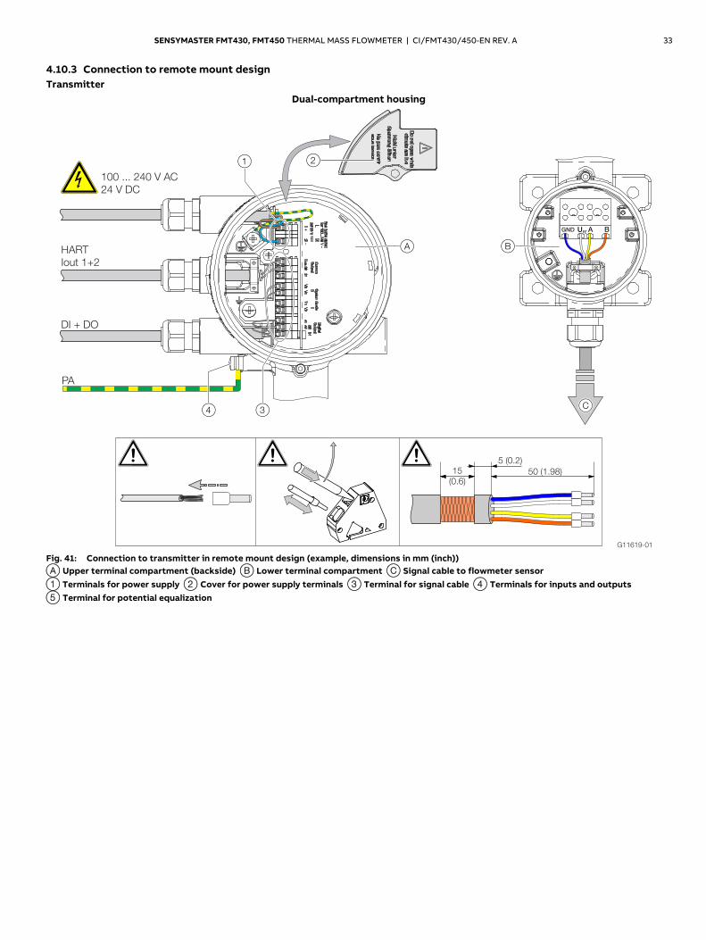
4.10.3 Connection to remote mount design Transmitter
Dual-compartment housing
Fig. 41: Connection to transmitter in remote mount design (example, dimensions in mm (inch)) A Upper terminal compartment (backside) B Lower terminal compartment C Signal cable to flowmeter sensor 1 Terminals for power supply 2 Cover for power supply terminals 3 Terminal for signal cable 4 Terminals for inputs and outputs 5 Terminal for potential equalization
34 SENSYMASTER FMT430, FMT450 THERMAL MASS FLOWMETER | CI/FMT430/450-EN REV. A
Single-compartment housing
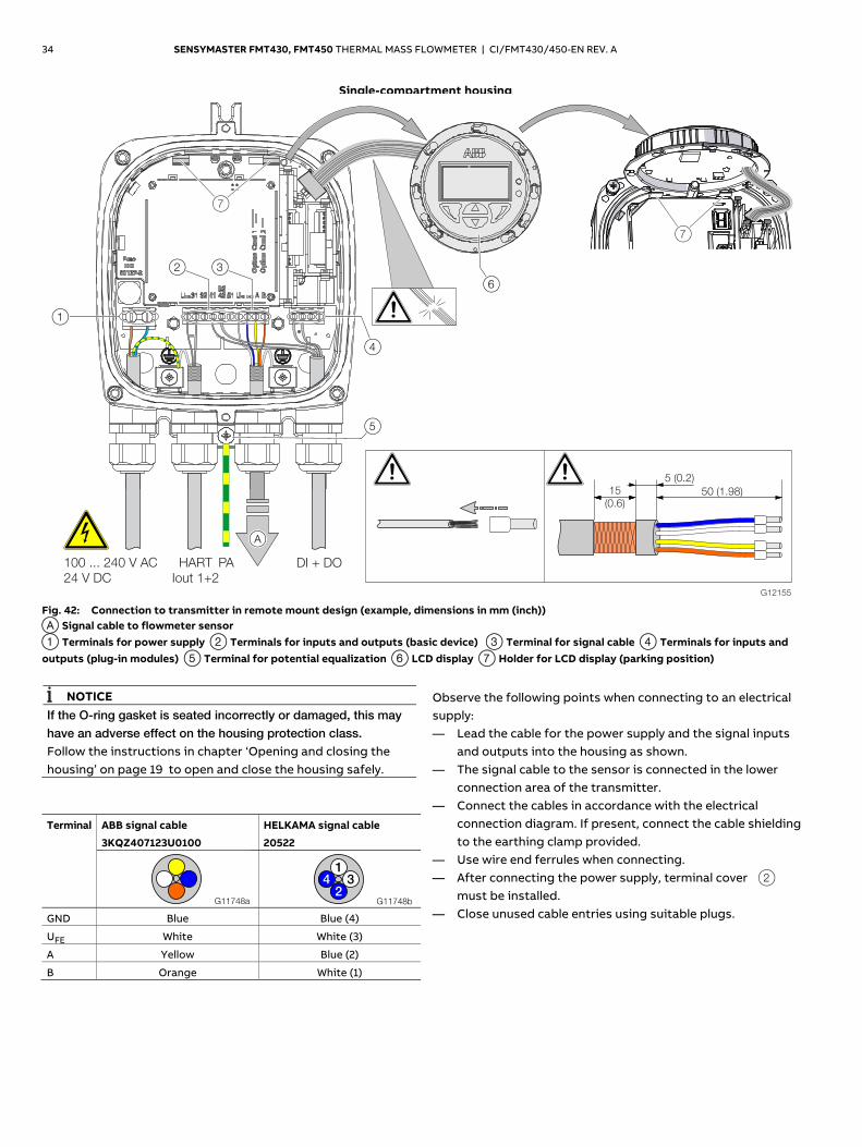
Fig. 42: Connection to transmitter in remote mount design (example, dimensions in mm (inch)) A Signal cable to flowmeter sensor 1 Terminals for power supply 2 Terminals for inputs and outputs (basic device) 3 Terminal for signal cable 4 Terminals for inputs and outputs (plug-in modules) 5 Terminal for potential equalization 6 LCD display 7 Holder for LCD display (parking position)
Change from one to two columns
NOTICE If the O-ring gasket is seated incorrectly or damaged, this may have an adverse effect on the housing protection class. Follow the instructions in chapter ‘Opening and closing the housing’ on page 19 to open and close the housing safely.
Terminal ABB signal cable
3KQZ407123U0100
HELKAMA signal cable
20522
GND Blue Blue (4)
UFE White White (3)
A Yellow Blue (2)
B Orange White (1)
Observe the following points when connecting to an electrical supply: — Lead the cable for the power supply and the signal inputs
and outputs into the housing as shown. — The signal cable to the sensor is connected in the lower
connection area of the transmitter. — Connect the cables in accordance with the electrical
connection diagram. If present, connect the cable shielding to the earthing clamp provided.
— Use wire end ferrules when connecting. — After connecting the power supply, terminal cover 2
must be installed. — Close unused cable entries using suitable plugs.
Change from two to one column
G11748a G11748b
1
234
SENSYMASTER FMT430, FMT450 THERMAL MASS FLOWMETER | CI/FMT430/450-EN REV. A 35
Flowmeter sensor
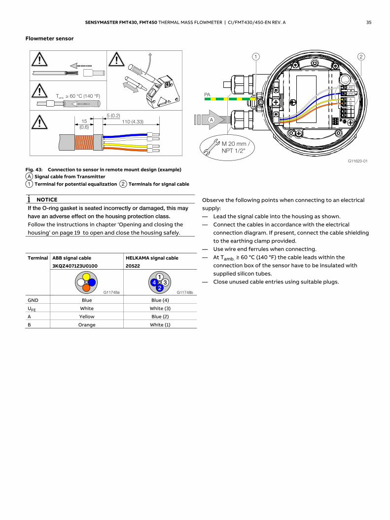
Fig. 43: Connection to sensor in remote mount design (example) A Signal cable from Transmitter 1 Terminal for potential equalization 2 Terminals for signal cable Change from one to two columns
NOTICE If the O-ring gasket is seated incorrectly or damaged, this may have an adverse effect on the housing protection class. Follow the instructions in chapter ‘Opening and closing the housing’ on page 19 to open and close the housing safely.
Terminal ABB signal cable
3KQZ407123U0100
HELKAMA signal cable
20522
GND Blue Blue (4)
UFE White White (3)
A Yellow Blue (2)
B Orange White (1)
Observe the following points when connecting to an electrical supply: — Lead the signal cable into the housing as shown. — Connect the cables in accordance with the electrical
connection diagram. If present, connect the cable shielding to the earthing clamp provided.
— Use wire end ferrules when connecting. — At Tamb. ≥ 60 °C (140 °F) the cable leads within the
connection box of the sensor have to be insulated with supplied silicon tubes.
— Close unused cable entries using suitable plugs. G11748a G11748b
1
234
36 SENSYMASTER FMT430, FMT450 THERMAL MASS FLOWMETER | CI/FMT430/450-EN REV. A
5 Commissioning
5.1 Safety instructions
CAUTION Risk of burns due to hot measuring media. The device surface temperature may exceed 70 °C (158 °F), depending on the measuring medium temperature! Before starting work on the device, make sure that it has cooled sufficiently.
If there is a chance that safe operation is no longer possible, take the device out of operation and secure it against unintended startup.
5.2 Hardware settings 5.2.1 Dual-compartment housing
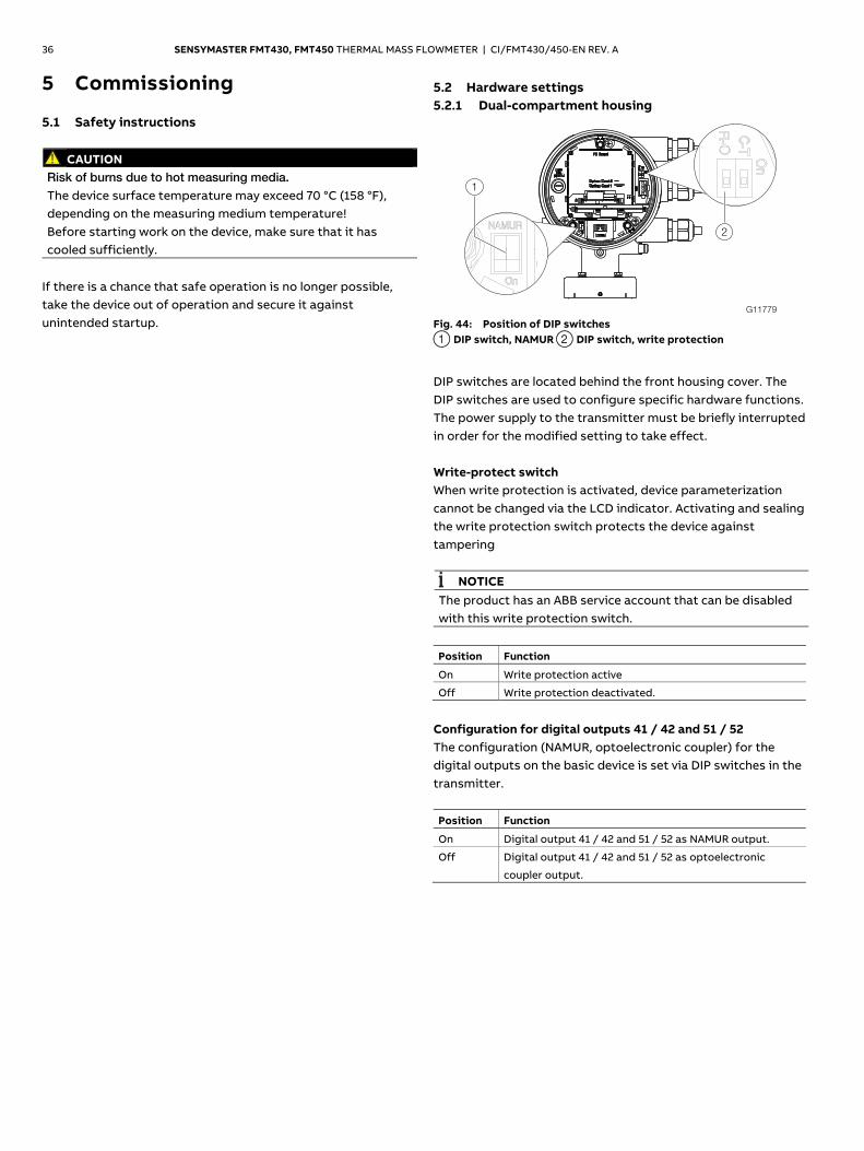
Fig. 44: Position of DIP switches 1 DIP switch, NAMUR 2 DIP switch, write protection
DIP switches are located behind the front housing cover. The DIP switches are used to configure specific hardware functions. The power supply to the transmitter must be briefly interrupted in order for the modified setting to take effect. Write-protect switch When write protection is activated, device parameterization cannot be changed via the LCD indicator. Activating and sealing the write protection switch protects the device against tampering
NOTICE The product has an ABB service account that can be disabled with this write protection switch.
Position Function
On Write protection active
Off Write protection deactivated.
Configuration for digital outputs 41 / 42 and 51 / 52 The configuration (NAMUR, optoelectronic coupler) for the digital outputs on the basic device is set via DIP switches in the transmitter. Position Function
On Digital output 41 / 42 and 51 / 52 as NAMUR output.
Off Digital output 41 / 42 and 51 / 52 as optoelectronic
coupler output.
G11779
1
2
SENSYMASTER FMT430, FMT450 THERMAL MASS FLOWMETER | CI/FMT430/450-EN REV. A 37
5.2.2 Single-compartment housing
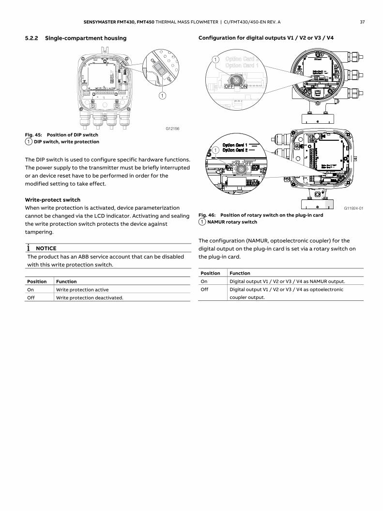
Fig. 45: Position of DIP switch 1 DIP switch, write protection
The DIP switch is used to configure specific hardware functions. The power supply to the transmitter must be briefly interrupted or an device reset have to be performed in order for the modified setting to take effect. Write-protect switch When write protection is activated, device parameterization cannot be changed via the LCD indicator. Activating and sealing the write protection switch protects the device against tampering.
NOTICE The product has an ABB service account that can be disabled with this write protection switch.
Position Function
On Write protection active
Off Write protection deactivated.
Configuration for digital outputs V1 / V2 or V3 / V4
Fig. 46: Position of rotary switch on the plug-in card 1 NAMUR rotary switch
The configuration (NAMUR, optoelectronic coupler) for the digital output on the plug-in card is set via a rotary switch on the plug-in card. Position Function
On Digital output V1 / V2 or V3 / V4 as NAMUR output.
Off Digital output V1 / V2 or V3 / V4 as optoelectronic
coupler output.
38 SENSYMASTER FMT430, FMT450 THERMAL MASS FLOWMETER | CI/FMT430/450-EN REV. A
5.3 Checks prior to commissioning The following points must be checked before commissioning the device: — The wiring must have been completed as described in the
chapter ‘Electrical connections’ on page 24 . — The correct grounding of the sensor. — The ambient conditions must meet the requirements set
out in the technical data. — The power supply must meet the requirements set out on
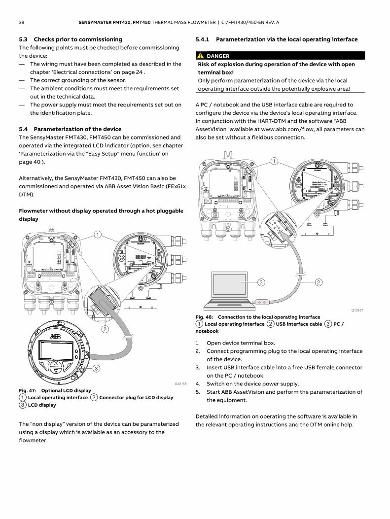
the identification plate. 5.4 Parameterization of the device The SensyMaster FMT430, FMT450 can be commissioned and operated via the integrated LCD indicator (option, see chapter ‘Parameterization via the "Easy Setup" menu function’ on page 40 ). Alternatively, the SensyMaster FMT430, FMT450 can also be commissioned and operated via ABB Asset Vision Basic (FEx61x DTM). Flowmeter without display operated through a hot pluggable display
Fig. 47: Optional LCD display 1 Local operating interface 2 Connector plug for LCD display 3 LCD display
The “non display” version of the device can be parameterized using a display which is available as an accessory to the flowmeter.
5.4.1 Parameterization via the local operating interface
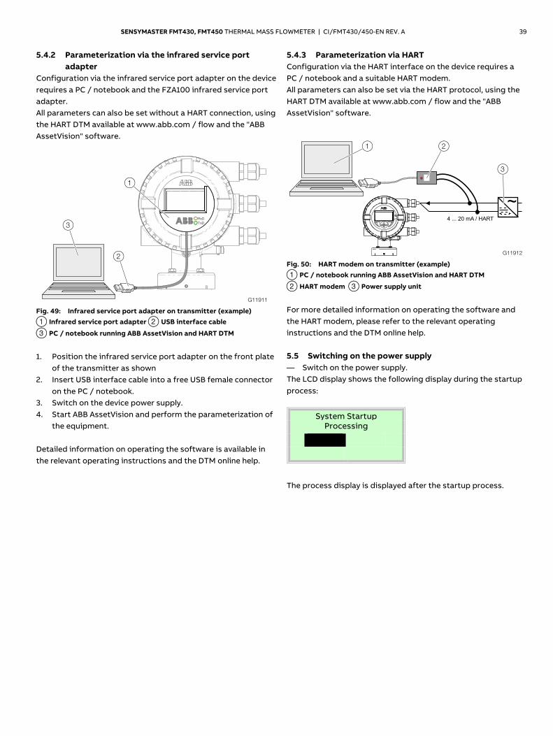
DANGER Risk of explosion during operation of the device with open terminal box! Only perform parameterization of the device via the local operating interface outside the potentially explosive area!
A PC / notebook and the USB interface cable are required to configure the device via the device's local operating interface. In conjunction with the HART-DTM and the software "ABB AssetVision" available at www.abb.com/flow, all parameters can also be set without a fieldbus connection.
Fig. 48: Connection to the local operating interface 1 Local operating interface 2 USB interface cable 3 PC / notebook
1. Open device terminal box. 2. Connect programming plug to the local operating interface
of the device. 3. Insert USB interface cable into a free USB female connector
on the PC / notebook. 4. Switch on the device power supply. 5. Start ABB AssetVision and perform the parameterization of
the equipment. Detailed information on operating the software is available in the relevant operating instructions and the DTM online help.
SENSYMASTER FMT430, FMT450 THERMAL MASS FLOWMETER | CI/FMT430/450-EN REV. A 39
5.4.2 Parameterization via the infrared service port adapter
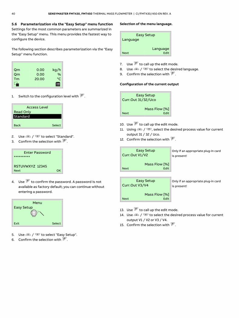
Configuration via the infrared service port adapter on the device requires a PC / notebook and the FZA100 infrared service port adapter. All parameters can also be set without a HART connection, using the HART DTM available at www.abb.com / flow and the "ABB AssetVision" software.
Fig. 49: Infrared service port adapter on transmitter (example) 1 Infrared service port adapter 2 USB interface cable
3 PC / notebook running ABB AssetVision and HART DTM
1. Position the infrared service port adapter on the front plate
of the transmitter as shown 2. Insert USB interface cable into a free USB female connector
on the PC / notebook. 3. Switch on the device power supply. 4. Start ABB AssetVision and perform the parameterization of
the equipment. Detailed information on operating the software is available in the relevant operating instructions and the DTM online help.
5.4.3 Parameterization via HART Configuration via the HART interface on the device requires a PC / notebook and a suitable HART modem. All parameters can also be set via the HART protocol, using the HART DTM available at www.abb.com / flow and the "ABB AssetVision" software.
Fig. 50: HART modem on transmitter (example) 1 PC / notebook running ABB AssetVision and HART DTM
2 HART modem 3 Power supply unit
For more detailed information on operating the software and the HART modem, please refer to the relevant operating instructions and the DTM online help. 5.5 Switching on the power supply — Switch on the power supply. The LCD display shows the following display during the startup process:
System Startup Processing
The process display is displayed after the startup process.
G11911
RxD
TxD3
2
1
G11912
1
~4 ... 20 mA / HART
2
3
40 SENSYMASTER FMT430, FMT450 THERMAL MASS FLOWMETER | CI/FMT430/450-EN REV. A
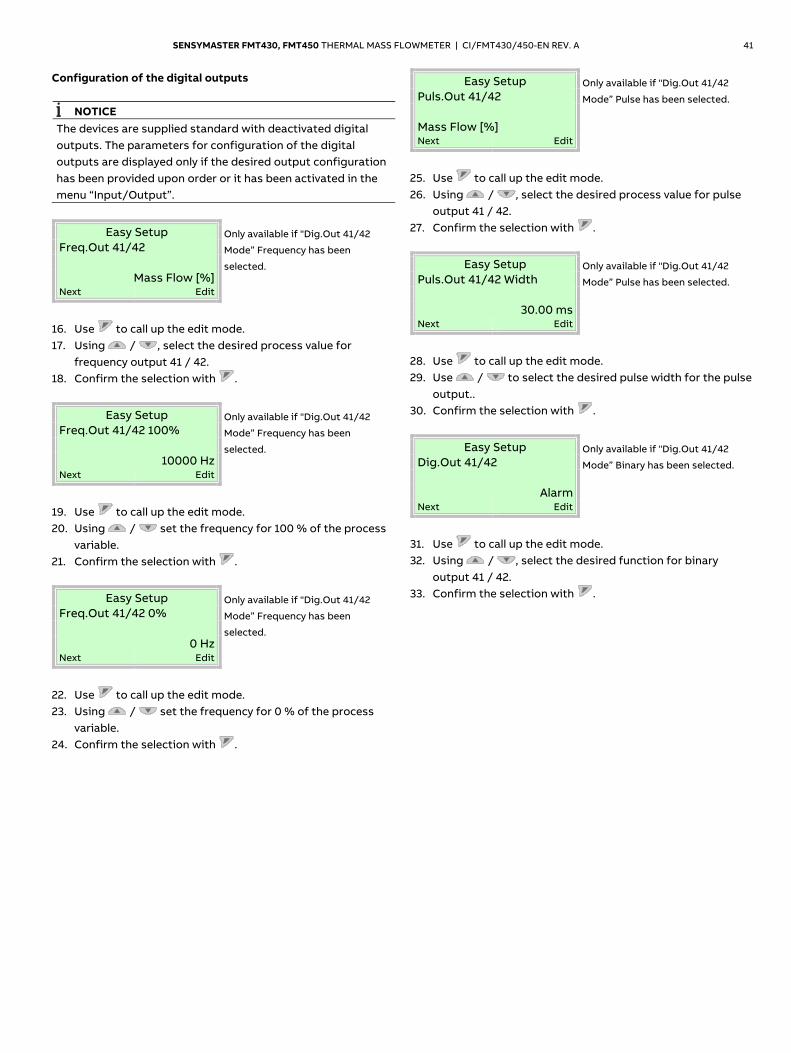
5.6 Parameterization via the "Easy Setup" menu function Settings for the most common parameters are summarized in the "Easy Setup" menu. This menu provides the fastest way to configure the device. The following section describes parameterization via the "Easy Setup" menu function.
Qm 0.00 kg/h Qm 0.00 % Tm 20.00 °C
1. Switch to the configuration level with .
Access Level Read Only Standard Back Select
2. Use / to select "Standard". 3. Confirm the selection with .
Enter Password ********** RSTUVWXYZ�12345 Next OK
4. Use to confirm the password. A password is not
available as factory default; you can continue without entering a password.
Menu Easy Setup
Exit Select
5. Use / to select "Easy Setup". 6. Confirm the selection with .
Selection of the menu language.
Easy Setup Language
Language Next Edit
7. Use to call up the edit mode. 8. Use / to select the desired language. 9. Confirm the selection with . Configuration of the current output
Easy Setup Curr.Out 31/32/Uco
Mass Flow [%] Next Edit
10. Use to call up the edit mode. 11. Using / , select the desired process value for current
output 31 / 32 / Uco. 12. Confirm the selection with .
Easy Setup Only if an appropriate plug-in card
is present! Curr.Out V1/V2
Mass Flow [%] Next Edit
Easy Setup Only if an appropriate plug-in card
is present! Curr.Out V3/V4
Mass Flow [%] Next Edit
13. Use to call up the edit mode. 14. Use / to select the desired process value for current
output V1 / V2 or V3 / V4. 15. Confirm the selection with .
SENSYMASTER FMT430, FMT450 THERMAL MASS FLOWMETER | CI/FMT430/450-EN REV. A 41
Configuration of the digital outputs
NOTICE The devices are supplied standard with deactivated digital outputs. The parameters for configuration of the digital outputs are displayed only if the desired output configuration has been provided upon order or it has been activated in the menu “Input/Output”.
Easy Setup Only available if "Dig.Out 41/42
Mode” Frequency has been
selected.
Freq.Out 41/42
Mass Flow [%] Next Edit
16. Use to call up the edit mode. 17. Using / , select the desired process value for
frequency output 41 / 42. 18. Confirm the selection with .
Easy Setup Only available if "Dig.Out 41/42
Mode” Frequency has been
selected.
Freq.Out 41/42 100%
10000 Hz Next Edit
19. Use to call up the edit mode. 20. Using / set the frequency for 100 % of the process
variable. 21. Confirm the selection with .
Easy Setup Only available if "Dig.Out 41/42
Mode” Frequency has been
selected.
Freq.Out 41/42 0%
0 Hz Next Edit
22. Use to call up the edit mode. 23. Using / set the frequency for 0 % of the process
variable. 24. Confirm the selection with .
Easy Setup Only available if "Dig.Out 41/42
Mode” Pulse has been selected. Puls.Out 41/42 Mass Flow [%] Next Edit
25. Use to call up the edit mode. 26. Using / , select the desired process value for pulse
output 41 / 42. 27. Confirm the selection with .
Easy Setup Only available if "Dig.Out 41/42
Mode” Pulse has been selected. Puls.Out 41/42 Width
30.00 ms Next Edit
28. Use to call up the edit mode. 29. Use / to select the desired pulse width for the pulse
output.. 30. Confirm the selection with .
Easy Setup Only available if "Dig.Out 41/42
Mode” Binary has been selected. Dig.Out 41/42
Alarm Next Edit
31. Use to call up the edit mode. 32. Using / , select the desired function for binary
output 41 / 42. 33. Confirm the selection with .
42 SENSYMASTER FMT430, FMT450 THERMAL MASS FLOWMETER | CI/FMT430/450-EN REV. A
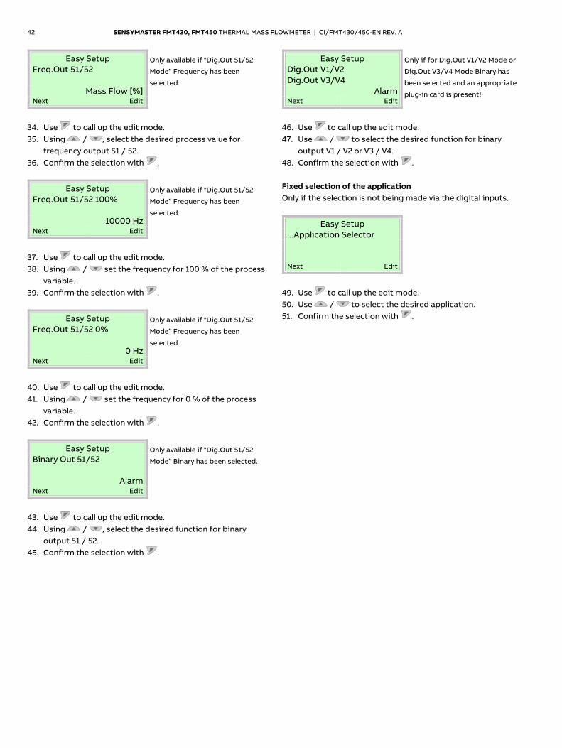
Easy Setup Only available if "Dig.Out 51/52
Mode” Frequency has been
selected.
Freq.Out 51/52
Mass Flow [%] Next Edit
34. Use to call up the edit mode. 35. Using / , select the desired process value for
frequency output 51 / 52. 36. Confirm the selection with .
Easy Setup Only available if "Dig.Out 51/52
Mode” Frequency has been
selected.
Freq.Out 51/52 100%
10000 Hz Next Edit
37. Use to call up the edit mode. 38. Using / set the frequency for 100 % of the process
variable. 39. Confirm the selection with .
Easy Setup Only available if "Dig.Out 51/52
Mode” Frequency has been
selected.
Freq.Out 51/52 0%
0 Hz Next Edit
40. Use to call up the edit mode. 41. Using / set the frequency for 0 % of the process
variable. 42. Confirm the selection with .
Easy Setup Only available if "Dig.Out 51/52
Mode” Binary has been selected. Binary Out 51/52
Alarm Next Edit
43. Use to call up the edit mode. 44. Using / , select the desired function for binary
output 51 / 52. 45. Confirm the selection with .
Easy Setup Only if for Dig.Out V1/V2 Mode or
Dig.Out V3/V4 Mode Binary has
been selected and an appropriate
plug-in card is present!
Dig.Out V1/V2 Dig.Out V3/V4
Alarm Next Edit
46. Use to call up the edit mode. 47. Use / to select the desired function for binary
output V1 / V2 or V3 / V4. 48. Confirm the selection with . Fixed selection of the application Only if the selection is not being made via the digital inputs.
Easy Setup ...Application Selector
Next Edit
49. Use to call up the edit mode. 50. Use / to select the desired application. 51. Confirm the selection with .
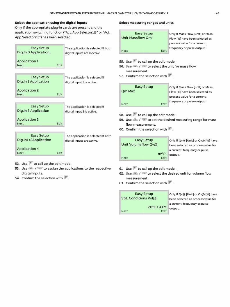
SENSYMASTER FMT430, FMT450 THERMAL MASS FLOWMETER | CI/FMT430/450-EN REV. A 43
Select the application using the digital inputs Only if the appropriate plug-in cards are present and the application switching function (“Act. App.Selector1|3” or “Act. App.Selector2|3”) has been selected.
Easy Setup The application is selected if both
digital inputs are inactive. Dig.In 0 Application Application 1 Next Edit
Easy Setup The application is selected if
digital input 1 is active. Dig.In 1 Application Application 2 Next Edit
Easy Setup The application is selected if
digital input 2 is active. Dig.In 2 Application Application 3 Next Edit
Easy Setup The application is selected if both
digital inputs are active. Dig.In1+2Application Application 4 Next Edit
52. Use to call up the edit mode. 53. Use / to assign the applications to the respective
digital inputs. 54. Confirm the selection with .
Select measuring ranges and units
Easy Setup Only if Mass Flow [unit] or Mass
Flow [%] have been selected as
process value for a current,
frequency or pulse output.
Unit Massflow Qm
Next Edit
55. Use to call up the edit mode. 56. Use / to select the unit for mass flow
measurement. 57. Confirm the selection with .
Easy Setup Only if Mass Flow [unit] or Mass
Flow [%] have been selected as
process value for a current,
frequency or pulse output.
Qm Max
Next Edit
58. Use to call up the edit mode. 59. Use / to set the desired measuring range for mass
flow measurement. 60. Confirm the selection with .
Easy Setup Only if Qv@ [Unit] or Qv@ [%] have
been selected as process value for
a current, frequency or pulse
output.
Unit Volumeflow Qv@
m3/h Next Edit
61. Use to call up the edit mode. 62. Use / to select the desired unit for volume flow
measurement. 63. Confirm the selection with .
Easy Setup Only if Qv@ [Unit] or Qv@ [%] have
been selected as process value for
a current, frequency or pulse
output.
Std. Conditions Vol@
20°C 1 ATM Next Edit
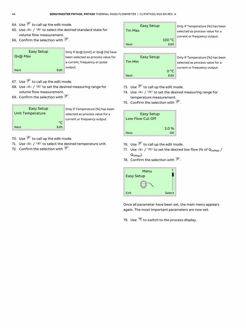
44 SENSYMASTER FMT430, FMT450 THERMAL MASS FLOWMETER | CI/FMT430/450-EN REV. A
64. Use to call up the edit mode. 65. Use / to select the desired standard state for
volume flow measurement. 66. Confirm the selection with .
Easy Setup Only if Qv@ [Unit] or Qv@ [%] have
been selected as process value for
a current, frequency or pulse
output.
Qv@ Max
Next Edit
67. Use to call up the edit mode. 68. Use / to set the desired measuring range for
volume flow measurement. 69. Confirm the selection with .
Easy Setup Only if Temperature [%] has been
selected as process value for a
current or frequency output.
Unit Temperature
°C Next Edit
70. Use to call up the edit mode. 71. Use / to select the desired temperature unit. 72. Confirm the selection with .
Easy Setup Only if Temperature [%] has been
selected as process value for a
current or frequency output.
Tm Max
100 °C Next Edit
Easy Setup Only if Temperature [%] has been
selected as process value for a
current or frequency output.
Tm Min
0 °C Next Edit
73. Use to call up the edit mode. 74. Use / to set the desired measuring range for
temperature measurement. 75. Confirm the selection with .
Easy Setup Low Flow Cut Off
3.0 % Next OK
76. Use to call up the edit mode. 77. Use / to set the desired low flow (% of QmMax /
QVMax). 78. Confirm the selection with .
Menu
Easy Setup
Exit Select
Once all parameter have been set, the main menu appears again. The most important parameters are now set. 79. Use to switch to the process display.
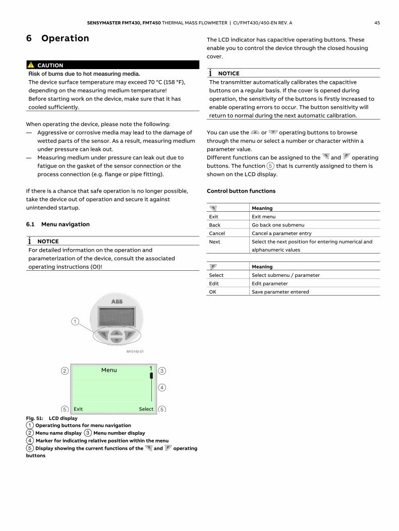
SENSYMASTER FMT430, FMT450 THERMAL MASS FLOWMETER | CI/FMT430/450-EN REV. A 45
6 Operation Safety instructions
CAUTION
Risk of burns due to hot measuring media. The device surface temperature may exceed 70 °C (158 °F), depending on the measuring medium temperature! Before starting work on the device, make sure that it has cooled sufficiently.
When operating the device, please note the following: — Aggressive or corrosive media may lead to the damage of
wetted parts of the sensor. As a result, measuring medium under pressure can leak out.
— Measuring medium under pressure can leak out due to fatigue on the gasket of the sensor connection or the process connection (e.g. flange or pipe fitting).
If there is a chance that safe operation is no longer possible, take the device out of operation and secure it against unintended startup. 6.1 Menu navigation
NOTICE For detailed information on the operation and parameterization of the device, consult the associated operating instructions (OI)!
M10145-01
1
2
5
Menu
3 4
5
Exit Select
Fig. 51: LCD display 1 Operating buttons for menu navigation 2 Menu name display 3 Menu number display 4 Marker for indicating relative position within the menu 5 Display showing the current functions of the and operating buttons
The LCD indicator has capacitive operating buttons. These enable you to control the device through the closed housing cover.
NOTICE The transmitter automatically calibrates the capacitive buttons on a regular basis. If the cover is opened during operation, the sensitivity of the buttons is firstly increased to enable operating errors to occur. The button sensitivity will return to normal during the next automatic calibration.
You can use the or operating buttons to browse through the menu or select a number or character within a parameter value. Different functions can be assigned to the and operating buttons. The function 5 that is currently assigned to them is shown on the LCD display.
Control button functions
Meaning Exit Exit menu Back Go back one submenu Cancel Cancel a parameter entry Next Select the next position for entering numerical and
alphanumeric values
Meaning Select Select submenu / parameter Edit Edit parameter OK Save parameter entered
Change from two to one column
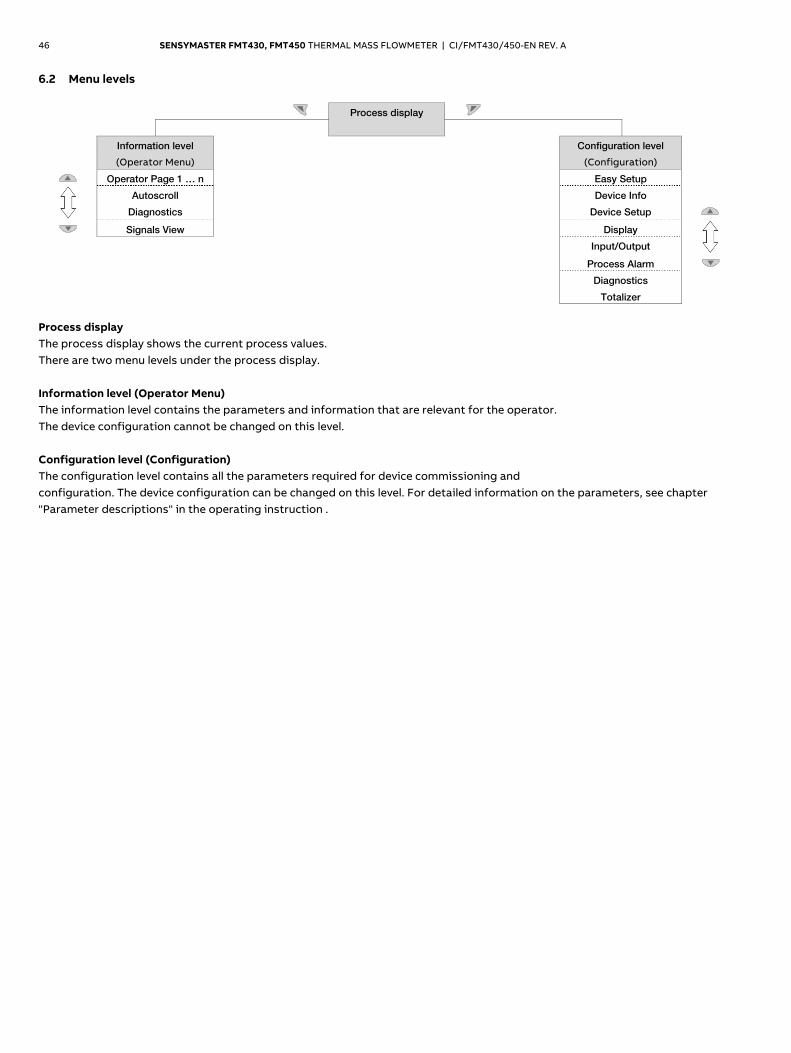
46 SENSYMASTER FMT430, FMT450 THERMAL MASS FLOWMETER | CI/FMT430/450-EN REV. A
6.2 Menu levels
Process display
Information level
(Operator Menu)
Configuration level
(Configuration)
Operator Page 1 … n Easy Setup
Autoscroll Device Info
Diagnostics Device Setup
Signals View Display
Input/Output
Process Alarm
Diagnostics
Totalizer
Process display The process display shows the current process values. There are two menu levels under the process display. Information level (Operator Menu) The information level contains the parameters and information that are relevant for the operator. The device configuration cannot be changed on this level. Configuration level (Configuration) The configuration level contains all the parameters required for device commissioning and configuration. The device configuration can be changed on this level. For detailed information on the parameters, see chapter "Parameter descriptions" in the operating instruction . Change from one to two columns
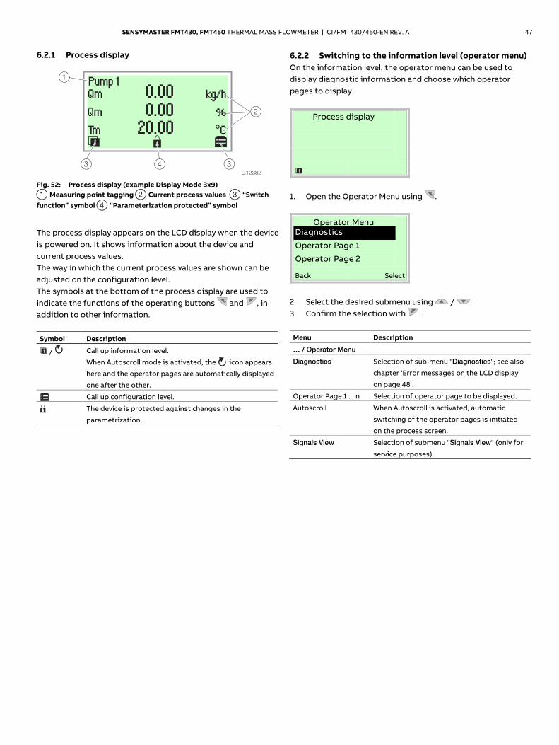
SENSYMASTER FMT430, FMT450 THERMAL MASS FLOWMETER | CI/FMT430/450-EN REV. A 47
6.2.1 Process display
G12382
1
43
2
3
Qm
Tm
0.000.00
20.00
kg/h
%
°C
Qm
Fig. 52: Process display (example Display Mode 3x9) 1 Measuring point tagging 2 Current process values 3 “Switch function” symbol 4 “Parameterization protected” symbol
The process display appears on the LCD display when the device is powered on. It shows information about the device and current process values. The way in which the current process values are shown can be adjusted on the configuration level. The symbols at the bottom of the process display are used to indicate the functions of the operating buttons and , in addition to other information. Symbol Description
/ Call up information level.
When Autoscroll mode is activated, the icon appears
here and the operator pages are automatically displayed
one after the other.
Call up configuration level.
The device is protected against changes in the
parametrization.
6.2.2 Switching to the information level (operator menu) On the information level, the operator menu can be used to display diagnostic information and choose which operator pages to display.
Process display
1. Open the Operator Menu using .
Operator Menu
Diagnostics
Operator Page 1
Operator Page 2
Back Select
2. Select the desired submenu using / . 3. Confirm the selection with . Menu Description
… / Operator Menu
Diagnostics Selection of sub-menu "Diagnostics"; see also
chapter ‘Error messages on the LCD display’
on page 48 .
Operator Page 1 ... n Selection of operator page to be displayed.
Autoscroll When Autoscroll is activated, automatic
switching of the operator pages is initiated
on the process screen.
Signals View Selection of submenu "Signals View" (only for
service purposes).
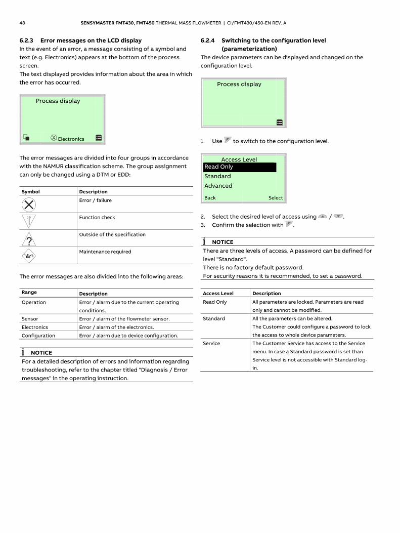
48 SENSYMASTER FMT430, FMT450 THERMAL MASS FLOWMETER | CI/FMT430/450-EN REV. A
6.2.3 Error messages on the LCD display In the event of an error, a message consisting of a symbol and text (e.g. Electronics) appears at the bottom of the process screen. The text displayed provides information about the area in which the error has occurred.
Process display
Electronics
The error messages are divided into four groups in accordance with the NAMUR classification scheme. The group assignment can only be changed using a DTM or EDD: Symbol Description
Error / failure
Function check
Outside of the specification
Maintenance required
The error messages are also divided into the following areas: Range Description Operation Error / alarm due to the current operating
conditions.
Sensor Error / alarm of the flowmeter sensor.
Electronics Error / alarm of the electronics.
Configuration Error / alarm due to device configuration.
NOTICE
For a detailed description of errors and information regarding troubleshooting, refer to the chapter titled "Diagnosis / Error messages" in the operating instruction.
6.2.4 Switching to the configuration level (parameterization)
The device parameters can be displayed and changed on the configuration level.
Process display
1. Use to switch to the configuration level.
Access Level
Read Only
Standard
Advanced
Back Select
2. Select the desired level of access using / . 3. Confirm the selection with .
NOTICE There are three levels of access. A password can be defined for level "Standard". There is no factory default password. For security reasons it is recommended, to set a password.
Access Level Description
Read Only All parameters are locked. Parameters are read
only and cannot be modified.
Standard All the parameters can be altered.
The Customer could configure a password to lock
the access to whole device parameters.
Service The Customer Service has access to the Service
menu. In case a Standard password is set than
Service level is not accessible with Standard log-
in.
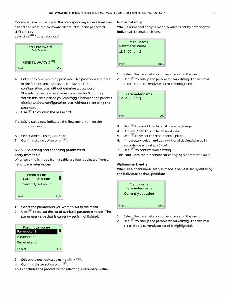
SENSYMASTER FMT430, FMT450 THERMAL MASS FLOWMETER | CI/FMT430/450-EN REV. A 49
Once you have logged on to the corresponding access level, you can edit or reset the password. Reset (status "no password defined") by selecting " " as a password.
Enter Password **********
QRSTUVWXYZ
Next OK
4. Enter the corresponding password. No password is preset
in the factory settings. Users can switch to the configuration level without entering a password. The selected access level remains active for 3 minutes. Within this time period you can toggle between the process display and the configuration level without re-entering the password.
5. Use to confirm the password. The LCD display now indicates the first menu item on the configuration level. 6. Select a menu using / . 7. Confirm the selection with . 6.2.5 Selecting and changing parameters Entry from table When an entry is made from a table, a value is selected from a list of parameter values.
Menu name
Parameter name
Currently set value
Next Edit
1. Select the parameters you want to set in the menu. 2. Use to call up the list of available parameter values. The
parameter value that is currently set is highlighted.
Parameter name
Parameter 1
Parameter 2
Parameter 3
Cancel OK
3. Select the desired value using / . 4. Confirm the selection with . This concludes the procedure for selecting a parameter value.
Numerical entry When a numerical entry is made, a value is set by entering the individual decimal positions.
Menu name
Parameter name
12.3456 [unit]
Next Edit
1. Select the parameters you want to set in the menu. 2. Use to call up the parameter for editing. The decimal
place that is currently selected is highlighted.
Parameter name
12.3456 [unit]
Next OK
3. Use to select the decimal place to change. 4. Use / to set the desired value. 5. Use to select the next decimal place. 6. If necessary select and set additional decimal places in
accordance with steps 3 to 4. 7. Use to confirm your setting. This concludes the procedure for changing a parameter value. Alphanumeric entry When an alphanumeric entry is made, a value is set by entering the individual decimal positions.
Menu name
Parameter name
Currently set value
Next Edit
1. Select the parameters you want to set in the menu. 2. Use to call up the parameter for editing. The decimal
place that is currently selected is highlighted.
50 SENSYMASTER FMT430, FMT450 THERMAL MASS FLOWMETER | CI/FMT430/450-EN REV. A
Parameter name
ABC………
ABCDEFGHIJKLMOPQ
Next OK
3. Use to select the decimal place to change. 4. Use / to set the desired value. 5. Use to select the next decimal place. 6. If necessary select and set additional decimal places in
accordance with steps 3 to 4. 7. Use to confirm your setting. This concludes the procedure for changing a parameter value. Exiting the setup For some menu items, values must be entered. If you don't want to change the parameter, you can exit the menu as described below. 1. Pressing (Next) repeatedly moves the cursor to the
right. Once the cursor reaches the end position, "Cancel" is displayed in the lower right of the screen.
2. terminates editing and exits the menu item. Use to return to the start.
NOTICE
The LCD display automatically returns to the process display three minutes after the last button has been actuated.
7 Maintenance
7.1 Safety instructions
DANGER Danger to life due to piping under pressure! Sensors which may eject during installation or removal in piping remaining under pressure may pose a danger to life. — Install or remove a sensor only if the piping is
depressurized. — As an alternative, use a pipe component with an
integrated replacement device.
WARNING Risk of injury due to live parts! When the housing is open, contact protection is not provided and EMC protection is limited. Before opening the housing, switch off the power supply.
CAUTION
Risk of burns due to hot measuring media. The device surface temperature may exceed 70 °C (158 °F), depending on the measuring medium temperature! Before starting work on the device, make sure that it has cooled sufficiently.
NOTICE
Damage to components! The electronic components of the printed circuit board can be damaged by static electricity (observe ESD guidelines). Make sure that the static electricity in your body is discharged before touching electronic components.
NOTICE
For detailed information on the maintenance of the device, consult the associated operating instructions (OI)!
8 Specification
NOTICE The detailed device data sheet is available in the download area at www.abb.com/flow.
9 Additional documents
NOTICE All documentation, declarations of conformity, and certificates are available in ABB's download area. www.abb.com/flow
"Parameter descriptions" in the operating instruction ”Installing the plug-in cards” in the operating instruction Trademarks ® HART is a registered trademark of FieldComm Group, Austin, Texas,
USA
® Kalrez and Kalrez SpectrumTM are registered trademarks of DuPont
Performance Elastomers.
™ Viton is a DuPont de Nemours trademark Change from two to one column
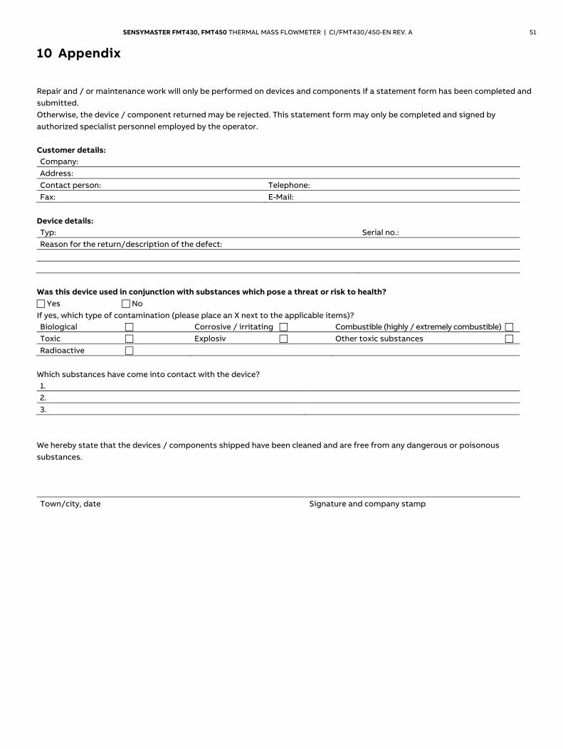
SENSYMASTER FMT430, FMT450 THERMAL MASS FLOWMETER | CI/FMT430/450-EN REV. A 51
10 Appendix Statement on the contamination of devices and components
Repair and / or maintenance work will only be performed on devices and components if a statement form has been completed and submitted. Otherwise, the device / component returned may be rejected. This statement form may only be completed and signed by authorized specialist personnel employed by the operator. Customer details: Company: Address: Contact person: Telephone: Fax: E-Mail:
Device details: Typ: Serial no.: Reason for the return/description of the defect:
Was this device used in conjunction with substances which pose a threat or risk to health? Yes No If yes, which type of contamination (please place an X next to the applicable items)? Biological Corrosive / irritating Combustible (highly / extremely combustible) Toxic Explosiv Other toxic substances Radioactive
Which substances have come into contact with the device? 1. 2. 3.
We hereby state that the devices / components shipped have been cleaned and are free from any dangerous or poisonous substances. Town/city, date Signature and company stamp

—
ABB Limited Measurement & Analytics Howard Road, St. Neots Cambridgeshire, PE19 8EU UK Tel: +44 (0) 870 600 6122 Fax: +44 (0)1480 213 339 Mail: [email protected] ABB Inc. Measurement & Analytics 125 E. County Line Road Warminster, PA 18974 USA Tel: +1 215 674 6000 Fax: +1 215 674 7183 abb.com/flow
ABB Automation Products GmbH Measurement & Analytics Dransfelder Str. 2 37079 Goettingen Germany Tel: +49 551 905-0 Fax: +49 551 905-777 Mail: [email protected]
CI/
FM
T4
30/4
50-E
N R
ev. A
10
.20
17
— We reserve the right to make technical changes or modify the contents of this document without prior notice. With regard to purchase orders, the agreed particulars shall prevail. ABB does not accept any responsibility whatsoever for potential errors or possible lack of information in this document. We reserve all rights in this document and in the subject matter and illustrations contained therein. Any reproduction, disclosure to third parties or utilization of its contents in whole or in parts – is forbidden without prior written consent of ABB. © ABB 2017 All rights reserved. 3KXF421015R4401