ABB MEASUREMENT & ANALYTICS | OpERATINg …
28
— ABB MEASUREMENT & ANALYTICS | OPERATING INSTRUCTION PGC5009 Fast gas chromatograph Further information Additional documentation on the PGC5009 fast gas chromatograph is available for download at www.abb.com/analytical. Alternatively simply scan this code. Measurement made easy
Transcript of ABB MEASUREMENT & ANALYTICS | OpERATINg …

— A B B M E A SU R EM ENT & A N A LY TI C S | O pER ATI Ng I NS TRUC TI O N
PGC5009 Fast gas chromatograph
Further informationAdditional documentation on the pgC5009 fast gas chromatograph is available for download at www.abb.com/analytical. Alternatively simply scan this code.
Measurement made easy

OI/PGC5009-EN, rev A 2
The Company We are an established world force in the design and manufacture of measurement products for industrial process control, flow measurement, gas and liquid analysis and environmental applications. As a part of ABB, a world leader in process automation technology, we offer customers application expertise, service and support worldwide. We are committed to teamwork, high quality manufacturing, advanced technology and unrivalled service and support. The quality, accuracy and performance of the Company’s products result from over 100 years of experience, combined with a continuous program of innovative design and development to incorporate the latest technology. Cyber Security Disclaimer This product is designed to be connected to and to communicate information and data via a network interface. It is the Customer's sole responsibility to provide and continuously ensure a secure connection between the product and Customer network or any other network (as the case may be). Customer shall establish and maintain any appropriate measures (such as but not limited to the installation of firewalls, application of authentication measures, encryption of data, installation of anti-virus programs, etc.) to protect the product, the network, its system and the interface against any kind of security breaches, unauthorized access, interference, intrusion, leakage and/or theft of data or information. ABB Inc. and its affiliates are not liable for damages and/or losses related to such security breaches, any unauthorized access, interference, intrusion, leakage and/or theft of data or information. Information for Users regarding the EU Directive 2012/19/EU on Waste Electrical and Electronic Equipment (WEEE)
ABB Industrial Automation, Measurement and Analytics, product manufacturing unit located at 3567 Jefferson Street North in Lewisburg WV 24901 USA, is committed to actively protecting the environment. The following product information is provided to the user regarding instruction to not dispose of WEEE as unsorted municipal waste but rather to collect WEEE separately. The user’s role in the management of WEEE is indispensable for the success of WEEE collection.
Such information necessitates the proper marking of Electrical and Electronic Equipment (EEE), referred to herein as the product, which could end up in rubbish bins or similar means of municipal waste collection. The product displays the crossed-out wheeled bin symbol, indicating a separate collection for the EEE and that the product conforms to the directive for Waste of Electrical and Electronic Equipment (WEEE). End of life disposal of the product is not intended for general household waste. Disposing of this product correctly will help save valuable resources and prevent any potential negative effects on human health and the environment.
Regarding our sustainability strategy, the course of action when developing new products is to ensure wherever possible that any and all national and international legal requirements, directives and standards of environmental protection and occupational safety are complied with, even if the regulatory requirement does not apply to the respective product. Our products are designed to ensure that with proper use of the product, there are no health hazards for the user nor any risk to the environment according to present knowledge.
Our products are manufactured from commercial materials in terms of environmental quality in such a way to ensure that during manufacture and use, the production of waste is reduced to a minimum. The environmentally friendly recovery and disposal of waste created after their use is guaranteed, and measured through the sustainability group of ABB.
Information for treatment facilities shall be provided by ABB regarding the preparation for re-use and treatment of new EEE placed for the first time on the European Union market. Such information may identify the different EEE components and materials, as well as the location of dangerous substances and mixtures. This information shall be made available by ABB to centers which prepare for re-use and treatment, and recycling facilities listed on the ABB website. Further information may be obtained through the local business unit of ABB.
This document shall serve for informational purposes only, no legal obligations are substantiated by any regulations.
PGC5009 PGC5009 Fast GC Oven Appendix Contents
OI/PGC5009-EN Rev. A 3
Contents
1 Safety and symbols ............................................. 4
2 Introduction ........................................................ 5 2.1 General description ................................................. 5 2.2 Oven assembly ......................................................... 5 2.3 Installation ............................................................... 6 2.4 Start-up and operation ............................................ 6
3 Software & setup ................................................ 7 3.1 Introduction ............................................................. 7 3.2 Background .............................................................. 7
3.2.1 ASTM distillation and petroleum industry 7 3.2.2 Summary ..................................................... 8
3.3 Simulated distillation ............................................... 8 3.3.1 Calibration run ............................................ 8 3.3.2 Blank run ..................................................... 9 3.3.3 Sample run ................................................ 10 3.3.4 Validation run ........................................... 10 3.3.5 ASTM-D2887 vs. ASTM-D3710 ................. 10
3.4 PGC5000 software ................................................. 10 3.4.1 Components ............................................. 10 3.4.2 Streams ..................................................... 11 3.4.3 Editing the time/temperature table ........ 12 3.4.4 Analysis ..................................................... 13 3.4.5 Schedule.................................................... 16 3.4.6 Reports ...................................................... 17
4 Technical description ......................................... 18 4.1 General description ............................................... 18 4.2 Functional description ........................................... 18 4.3 Column housing ..................................................... 19
4.3.1 Liquid sample valve ................................... 19 4.3.2 Column ...................................................... 19 4.3.3 Detector .................................................... 19
4.4 Electronics housing ................................................ 19 5 Maintenance and repair .................................... 20 5.1 Maintenance procedures ...................................... 20 5.2 FID repair ................................................................ 20
5.2.1 Removing insulation and heater block .... 20 5.2.2 Replacing FID components ....................... 21 5.2.3 Installing insulation and heater block ...... 21
5.3 Column replacement ............................................. 21 5.3.1 Removing the column ............................... 22 5.3.2 Installing the column ................................ 23
5.4 Liquid sample valve repair ..................................... 24 5.4.1 Removing the LSV ..................................... 24 5.4.2 Repairing the LSV ...................................... 25 5.4.3 Installing the LSV ....................................... 25
6 Replacement parts ............................................ 26 6.1 Ordering information ............................................. 26 6.2 Oven assembly ....................................................... 26

PGC5000 Generation 2 PGC5009 Fast GC Oven Appendix 1 Safety and symbols
OI/PGC5009-EN Rev. A 4
1 Safety and symbols
The following symbols are used in this manual to alert the user to possible hazards and to provide additional information.
Indicates that the referred item can be hot and should not be touched without care.
Indicates that a risk of electrical shock and/or electrocution exists.
Indicates a potential hazard which could cause serious injury and/or death, or indicates the presence of a hazard which could result in corruption of software or damage to equipment or property.
Indicates that referenced items are susceptible to Electrostatic Discharge (ESD) damage and should not be touched without ESD safe handling tools.
Alerts the user to pertinent facts and conditions.
PGC5009 PGC5009 Fast GC Oven Appendix 2 Introduction
OI/PGC5009-EN Rev. A 5
2 Introduction
2.1 General description The Process Gas Chromatograph, Fast Simulated Distillation PGC5009 (Fast GC), analyzes samples with wide variations in component boiling points or molecular weights, much faster than standard process gas chromatographs. It automatically samples and analyzes process streams, using the analyzer’s Master Controller to control analytical functions. It maintains the same look and feel as the standard PGC5000 Process Gas Chromatograph. The Fast GC Oven Assembly works with all models of the PGC5000 Master Controller (PGC5000 and PGC5000 Generation 2).
Each analyzer has a temperature code (T-Rating) listed on the nameplate. This T-Rating indicates the temperature classification of the area in which the analyzer has been designed to operate. The customer determines and supplies the T-Ratings and area classifications for analyzer locations Because temperature programming is application specific, it is set at the factory. Temperature settings for the heated zones can be found in the Data Package shipped with the analyzer. This information should be used as a reference during setup and startup, and when performing troubleshooting and calibration. If adjustments need to be made, they should be made according to the information in the Data Package.
This manual provides information specific to the Fast GC. All material and functions that are common to the PGC5000 are described in the following manuals:
Operating Instructions (OI/PGC5000) and Service Instructions (SI/PGC5000) for PGC5000 analyzers. Operating Instructions (OI/PGC5000/GEN2) and Service Instructions (SI/PGC5000/GEN2) for PGC5000 Generation 2 analyzers.
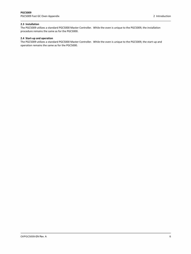
The insulated, air-heated Oven Assembly (see Figure 2.1) may be mounted on a wall, a rack, or a floor stand
ColumnHousing
Electronics Housing
Fig. 2.1. Typical PGC5009 Oven Assembly
2.2 Oven assembly The Oven Assembly consists of a Column Housing and an Electronics Housing. The Column Housing (left side of Oven Assembly) contains an analytical column, detector, and liquid sample valve. The Electronics Housing (right side of Oven Assembly) contains the power supply, Detector Amplifier PCB, DTC Control PCB, EPC Control PCB, and EPC Controller Assembly. The detector for the Fast GC is the flame ionization detector (FID).
PGC5009 PGC5009 Fast GC Oven Appendix 2 Introduction
OI/PGC5009-EN Rev. A 6
2.3 Installation The PGC5009 utilizes a standard PGC5000 Master Controller. While the oven is unique to the PGC5009, the installation procedure remains the same as for the PGC5000.
2.4 Start-up and operation The PGC5009 utilizes a standard PGC5000 Master Controller. While the oven is unique to the PGC5009, the start-up and operation remains the same as for the PGC5000.
PGC5009 PGC5009 Fast GC Oven Appendix 3 Software & Setup
OI/PGC5009-EN Rev. A 7
3 Software & Setup
3.1 Introduction This is an operational guide in the implementation and maintenance of various data, tables, and requests necessary for Simulated Distillation operation. It is assumed that the operator possesses the fundamental skills required for normal operation of the controller using the Front Panel & Remote User Interface. If one is new to this system, a review of the PGC5000 Operations elsewhere in this manual is recommended.
An examination of the following documents is recommended: ASTM D-2887 "Boiling Range Distribution of Petroleum Fractions by Gas Chromatography" ASTM D-3710 "Boiling Range Distribution of Gasoline and Gasoline Fractions by Gas Chromatography" ASTM D-86 "Distillation of Petroleum Products" ASTM STP 577 "Calculation of Physical Properties of Petroleum Products from Gas Chromatographic Analyses"
3.2 Background
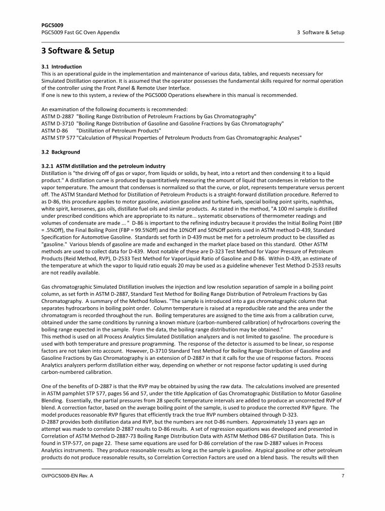
3.2.1 ASTM distillation and the petroleum industry Distillation is "the driving off of gas or vapor, from liquids or solids, by heat, into a retort and then condensing it to a liquid product." A distillation curve is produced by quantitatively measuring the amount of liquid that condenses in relation to the vapor temperature. The amount that condenses is normalized so that the curve, or plot, represents temperature versus percent off. The ASTM Standard Method for Distillation of Petroleum Products is a straight-forward distillation procedure. Referred to as D-86, this procedure applies to motor gasoline, aviation gasoline and turbine fuels, special boiling point spirits, naphthas, white spirit, kerosenes, gas oils, distillate fuel oils and similar products. As stated in the method, "A 100 ml sample is distilled under prescribed conditions which are appropriate to its nature... systematic observations of thermometer readings and volumes of condensate are made ... " D-86 is important to the refining industry because it provides the Initial Boiling Point (IBP = .5%Off), the Final Boiling Point (FBP = 99.5%0ff) and the 10%Off and 50%Off points used in ASTM method D-439, Standard Specification for Automotive Gasoline. Standards set forth in D-439 must be met for a petroleum product to be classified as "gasoline." Various blends of gasoline are made and exchanged in the market place based on this standard. Other ASTM methods are used to collect data for D-439. Most notable of these are D-323 Test Method for Vapor Pressure of Petroleum Products (Reid Method, RVP), D-2533 Test Method for VaporLiquid Ratio of Gasoline and D-86. Within D-439, an estimate of the temperature at which the vapor to liquid ratio equals 20 may be used as a guideline whenever Test Method D-2533 results are not readily available.
Gas chromatographic Simulated Distillation involves the injection and low resolution separation of sample in a boiling point column, as set forth in ASTM D-2887, Standard Test Method for Boiling Range Distribution of Petroleum Fractions by Gas Chromatography. A summary of the Method follows. "The sample is introduced into a gas chromatographic column that separates hydrocarbons in boiling point order. Column temperature is raised at a reproducible rate and the area under the chromatogram is recorded throughout the run. Boiling temperatures are assigned to the time axis from a calibration curve, obtained under the same conditions by running a known mixture (carbon-numbered calibration) of hydrocarbons covering the boiling range expected in the sample. From the data, the boiling range distribution may be obtained." This method is used on all Process Analytics Simulated Distillation analyzers and is not limited to gasoline. The procedure is used with both temperature and pressure programming. The response of the detector is assumed to be linear, so response factors are not taken into account. However, D-3710 Standard Test Method for Boiling Range Distribution of Gasoline and Gasoline Fractions by Gas Chromatography is an extension of D-2887 in that it calls for the use of response factors. Process Analytics analyzers perform distillation either way, depending on whether or not response factor updating is used during carbon-numbered calibration.
One of the benefits of D-2887 is that the RVP may be obtained by using the raw data. The calculations involved are presented in ASTM pamphlet STP 577, pages 56 and 57, under the title Application of Gas Chromatographic Distillation to Motor Gasoline Blending. Essentially, the partial pressures from 28 specific temperature intervals are added to produce an uncorrected RVP of blend. A correction factor, based on the average boiling point of the sample, is used to produce the corrected RVP figure. The model produces reasonable RVP figures that efficiently track the true RVP numbers obtained through D-323. D-2887 provides both distillation data and RVP, but the numbers are not D-86 numbers. Approximately 13 years ago an attempt was made to correlate D-2887 results to D-86 results. A set of regression equations was developed and presented in Correlation of ASTM Method D-2887-73 Boiling Range Distribution Data with ASTM Method D86-67 Distillation Data. This is found in STP-577, on page 22. These same equations are used for D-86 correlation of the raw D-2887 values in Process Analytics instruments. They produce reasonable results as long as the sample is gasoline. Atypical gasoline or other petroleum products do not produce reasonable results, so Correlation Correction Factors are used on a blend basis. The results will then
PGC5009 PGC5009 Fast GC Oven Appendix 3 Software & Setup
OI/PGC5009-EN Rev. A 8
closely match the lab D-86 data. The results are much more repeatable and precise, agreeing from one instrument to another, than any D-86 results, whether obtained manually or automatically.
3.2.2 Summary Simulated Distillation Analyzers are NOT intended to be used to obtain final specification data for gasoline (D-439) or any other petroleum product. Lab tests will still have to be made according to ASTM methods; certification remains with the lab. The GC provides continuous monitoring and evaluation for control and maintenance of an on-spec product.
3.3 Simulated distillation Chromatographic Simulated Distillation is a technique that measures the amount of sample elution (%Off) with respect to time and temperature. Once the %Off is plotted against temperature, the Simulated Distillation curve for the sample is obtained. From the raw data and the curve, various points, intervals (slices or fractions), and calculated parameters may be determined which aid the producer in blending and meeting the desired specifications for a final product. Two of the most important points are the Initial Boiling Point (IBP) and the Final Boiling Point (FBP). They are defined as the temperatures at which 0.5% and 99.5% of the total sample have eluted from the column. The amounts of iC4, iC5, and other "light" carbon compounds are of importance to gasoline blenders, as are the parameters Reid Vapor Pressure (RVP) and the temperatures at various Vapor to Liquid (V /L) Ratios. These and other values are either directly or indirectly (by correlation, calculation, etc.) obtainable from the raw chromatographic results. The PGC5000 Software contains features specifically designed to complement the 5009 Fast GC and Temperature Programmed Ovens. These analyzers provide extremely good repeatability and reasonable cycle times. Repeatability is maintained due to the fact that a linear "ramping" of the column temperature, or pressure, yields elution times that are linear with respect to carbon number. Once a boiling point/time relationship is established through a calibration cycle, later interpolation between corresponding points on the time/temperature line should be accurate. Thus, the %Off at various temperatures may be measured and reported precisely.
Simulated Distillation requires three distinctively different "runs", and optionally a fourth. They are the Calibration Run, Blank Run, Sample Run and optionally, the Validation Run.
3.3.1 Calibration run The Calibration Run injects a standard sample consisting of appropriate standard components, referred to as Carbon Number Components, whose boiling points are known. Results from the Cal Run establish the Time/Temperature and Response Factor (RF) relationships, as required for the selected method. The significance of the Time/Temperature relationship is explained following.
Calibration may be activated manually or automatically. Analyzers must be calibrated periodically due to temperature (or pressure) drift and column aging. A calibration must be done prior to the first analysis, otherwise, the resulting data will be meaningless.

PGC5009 PGC5009 Fast GC Oven Appendix 3 Software & Setup
OI/PGC5009-EN Rev. A 9
Carbon Number Calibration uses standard peak analysis to measure the Retention Time and Response Factor for the defined set of Carbon Number Components used to generate the time vs. boiling point relationship. For example, the standard 19 components of an ASTM-D3710 Carbon Number Calibration are shown in Figure 3.1.
Fig. 3.1. Standard Components
The Time/Temperature Relationship is the heart of gas chromatographic simulated distillation. Assume that the analyzer is calibrated and a plot of Retention Time vs. Temperature is as shown in Figure 3.2. The vertical axis represents boiling points and the horizontal axis is time into the analysis cycle.
To find the %Off at 100 degrees, move horizontally from 100 degrees on the temperature axis is until coming to the line. Drop vertically to discover the corresponding time, 66 seconds. The Analyzer determines the %Off by dividing the accumulated area found at 66 seconds by the total analysis area.
Fig. 3.2. Retention Time vs Temperature
To find the temperature corresponding to 50% Off, reverse the procedure. Search the stored chromatogram until 50% of the total area is found. Assume this corresponds to 66 seconds. Move vertically from 66 seconds on the time axis to the line intersection. Proceed horizontally along the temperature axis; the temperature is 100 degrees.
The Time/Temperature Relationship is only defined between the endpoints, which are the retention time of the first and last components in the Carbon Number Calibration. Meaningful results cannot be expected outside these boundaries.
3.3.2 Blank run A Blank Run is an analysis cycle WITHOUT a sample injection. The data collected is stored in a Blank Report and represents detector background noise and column bleed contributions for each sample. The temperature and pressure programs are executed in precisely the same manner as for the regular analysis. The Blank Run should be conducted after the calibration procedure and before the analysis run, as often as necessary. It may be initiated manually by the operator, or automatically through the TOD Schedule table.
-100-50
050
100150200250300
0 50 100 150
Time vs. Temperature
PGC5009 PGC5009 Fast GC Oven Appendix 3 Software & Setup
OI/PGC5009-EN Rev. A 10
3.3.3 Sample run During a Sample Run (Analysis Run), the process sample to undergo Simulated Distillation is injected. Gating for data collection is turned on right after the time of the first Cal peak and it is turned off right before the time of the last Cal peak. It is essential that the sample fully elutes between the times of the first and last Calibration peaks. The Controller collects data from the detector 100 times per second and integrates each sample into the total area. The corresponding Blank Run data, sample for sample, is subtracted and the difference updates the point data with the cumulative area count. If ASTM-D3710 is to be employed, then Response Factor values of the Carbon Number Components are used to adjust the detector data profile before calculations are performed.
3.3.4 Validation run During a Validation Run, all procedures and calculations are performed just like a Sample Run. In addition, for each included Component in the analysis, a deviation value is calculated relative to the Validation value defined in the Component Definition. This value is included in the Analysis Report.
3.3.5 ASTM-D2887 vs. ASTM-D3710 An ASTM-D2887 setting does not employ response factors during the collection of the detector signal data. All response factors included in a Sample Run analysis are ignored. Usually 2887 encompasses non-gasoline applications. An ASTM-D3710 setting uses response factors to adjust detector data and any small non-linearities in the detector are taken into account. The response factors are also used in the 4 discrete peak measurements ( NC3, IC4, NC4, IC5) specified in ASTM-D3710. ASTM-D3710 is a gasoline specific application.
D-86 Correlation may be added with Script.
3.4 PGC5000 software
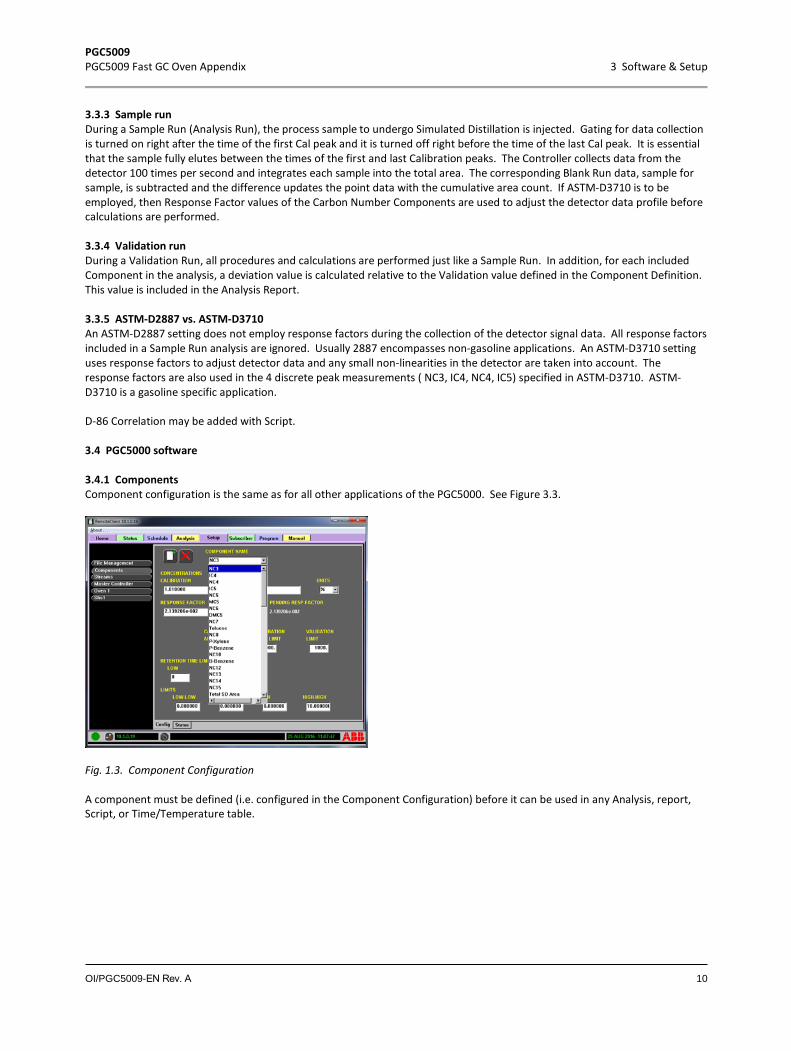
3.4.1 Components Component configuration is the same as for all other applications of the PGC5000. See Figure 3.3.
Fig. 1.3. Component Configuration
A component must be defined (i.e. configured in the Component Configuration) before it can be used in any Analysis, report, Script, or Time/Temperature table.
PGC5009 PGC5009 Fast GC Oven Appendix 3 Software & Setup
OI/PGC5009-EN Rev. A 11
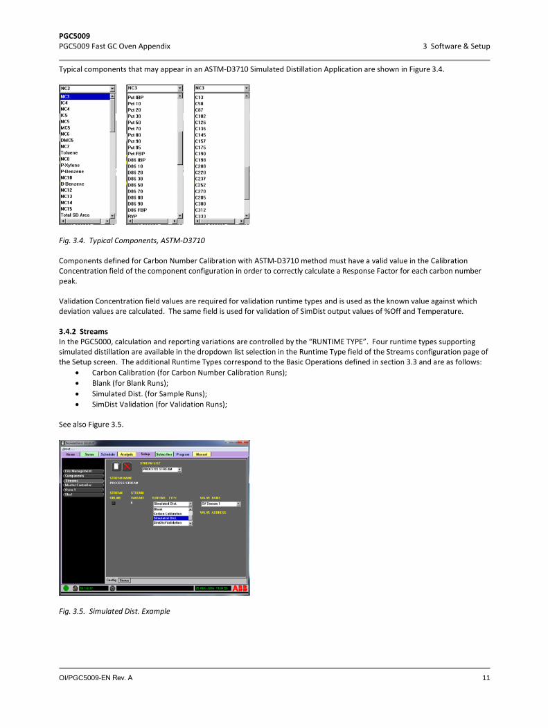
Typical components that may appear in an ASTM-D3710 Simulated Distillation Application are shown in Figure 3.4.
Fig. 3.4. Typical Components, ASTM-D3710
Components defined for Carbon Number Calibration with ASTM-D3710 method must have a valid value in the Calibration Concentration field of the component configuration in order to correctly calculate a Response Factor for each carbon number peak.
Validation Concentration field values are required for validation runtime types and is used as the known value against which deviation values are calculated. The same field is used for validation of SimDist output values of %Off and Temperature.
3.4.2 Streams In the PGC5000, calculation and reporting variations are controlled by the “RUNTIME TYPE”. Four runtime types supporting simulated distillation are available in the dropdown list selection in the Runtime Type field of the Streams configuration page of the Setup screen. The additional Runtime Types correspond to the Basic Operations defined in section 3.3 and are as follows:
• Carbon Calibration (for Carbon Number Calibration Runs); • Blank (for Blank Runs); • Simulated Dist. (for Sample Runs); • SimDist Validation (for Validation Runs);
See also Figure 3.5.
Fig. 3.5. Simulated Dist. Example

PGC5009 PGC5009 Fast GC Oven Appendix 3 Software & Setup
OI/PGC5009-EN Rev. A 12
When the Run Type of “Carbon Calibration” is selected, also included in the configuration page is the Time/Temperature table. (See Figure 3.6.)
Fig. 3.6. Carbon Calibration Example
3.4.3 Editing the time/temperature table Time and Temperature values must be in increasing order in the table. For a new table, since a values are initialized to zero, this will necessitate starting at the last entry and inserting the values from the highest to the lowest, working backward through the table.
Temperature values should be in the scale of units desired for report output (Kelvin, Celsius, Fahrenheit, etc.). Units are not used in the calculation, so as long as the values are correct, the output will follow.
The Components in the Time/Temperature table should correspond to the components defined in the Carbon Number Calibration analysis that will be used with the calibration stream. Time entries will be automatically updated in the table from the retention time results from a Calibration Run. Figure 3.7 shows the features of the Time/Temperature Table.
Select Line
Add Component
DeleteLine
Fig. 3.7. Tme vs Temperature Example
COMPONENT – This field is not directly editable. A component may be added via the Add Component Button or deleted. TIME – This is an Edit field. Click inside the box and use a keyboard to change the value. TEMPERATURE – This is an Edit field. Click inside the box and use a keyboard to change the value.
Select Line Checkbox – Select one or more lines for Add and Delete operations. For delete, all selected lines are deleted.

PGC5009 PGC5009 Fast GC Oven Appendix 3 Software & Setup
OI/PGC5009-EN Rev. A 13
Add Component Icon – When the Add Component icon is selected, a list of all defined components appears (see Figure 3.8). Click a component in the list to choose it. The new component is added after the selected (or first selected) line. If none are selected, the component is added to the end of the list.
Fig. 3.8. Add Component Example
Delete Line Icon – When the Delete Line icon is selected, it removes all selected lines form the table.
3.4.4 Analysis Analysis development is the same is other PGC5000 applications. Specific to Simulated Distillation are three Time Coded Functions (TCFs), as shown in Figure 3.9.
• Inject• Simulated Dist. • Component SD
Inject TCF
Simulated Dist TCF Component SD TCF
Fig. 3.9. Simulated Distillation TCFs
The “Inject” TCF is functionally equivalent to a “Valve On” TCF, except an Inject is automatically suppressed when the analysis is coupled with a Blank stream in the schedule. Operating the inject valve must be performed using this TCF, otherwise, the Blank Run will not be performed properly.
PGC5009 PGC5009 Fast GC Oven Appendix 3 Software & Setup
OI/PGC5009-EN Rev. A 14
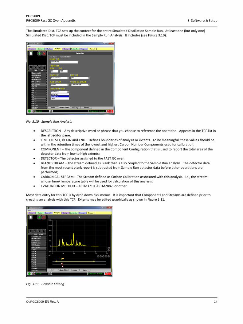
The Simulated Dist. TCF sets up the context for the entire Simulated Distillation Sample Run. At least one (but only one) Simulated Dist. TCF must be included in the Sample Run Analysis. It includes (see Figure 3.10).
Fig. 3.10. Sample Run Analysis
• DESCRIPTION – Any descriptive word or phrase that you choose to reference the operation. Appears in the TCF list inthe left editor pane;
• TIME OFFSET, BEGIN and END – Defines boundaries of analysis or extents. To be meaningful, these values should be within the retention times of the lowest and highest Carbon Number Components used for calibration;
• COMPONENT – The component defined in the Component Configuration that is used to report the total area of the detector data from low to high extents;
• DETECTOR – The detector assigned to the FAST GC oven;• BLANK STREAM – The stream defined as Blank that is also coupled to the Sample Run analysis. The detector data
from the most recent blank report is subtracted from Sample Run detector data before other operations are performed;
• CARBON CAL STREAM – The Stream defined as Carbon Calibration associated with this analysis. I.e., the streamwhose Time/Temperature table will be used for calculation of this analysis;
• EVALUATION METHOD – ASTM3710, ASTM2887, or other.
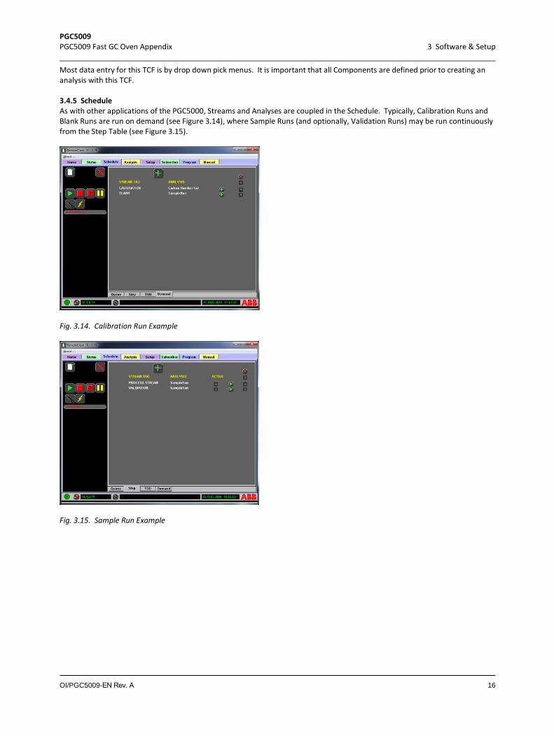
Most data entry for this TCF is by drop down pick menus. It is important that Components and Streams are defined prior to creating an analysis with this TCF. Extents may be edited graphically as shown in Figure 3.11.
Fig. 3.11. Graphic Editing

PGC5009 PGC5009 Fast GC Oven Appendix 3 Software & Setup
OI/PGC5009-EN Rev. A 15
A “Component SD” TCF is required for reported output of the Sample Run analysis • DESCRIPTION - Any descriptive word or phrase that you choose to reference the operation. Appears in the TCF list in
the left editor pane; • TIME OFFSET – Must be unique for each component. Not expected to match time into cycle that a component will
resolve to, but generally should reflect the order that components will resolve. E.g. 50% Off is expected before 75% Off, so the 50% Off TCF should have a lower TIME OFFSET than the 75% Off TCF. All TIME OFFSET’s must fall between the low and high extents defined in the Simulated Dist. TCF;
• COMPONENT - The component defined in the Component Configuration that is used to report the value associatedwith the current TCF;
• DETECTOR – The detector assigned to the FAST GC oven;• COMPONENT RESULT – “Temperature” or “Percent Off” – the intended type of the reported output desired for the
TCF;• AT PERCENT OFF – When temperature is selected under COMPONENT RESULT, you will choose a Percent Off value for
which you want the temperature (see Figure 3.12).
Fig. 3.12. Temperature at Percent Off
• AT BOILING POINT – When Percent Off is selected under COMPONENT RESULT, you will choose a Temperature forwhich you want the Percent Off (see Figure 3.13);
Fig. 3.13. Percent Off at Boiling Point
• CORRELATION OFFSET – A fixed value that is added to the result before it is reported.
PGC5009 PGC5009 Fast GC Oven Appendix 3 Software & Setup
OI/PGC5009-EN Rev. A 16
Most data entry for this TCF is by drop down pick menus. It is important that all Components are defined prior to creating an analysis with this TCF.
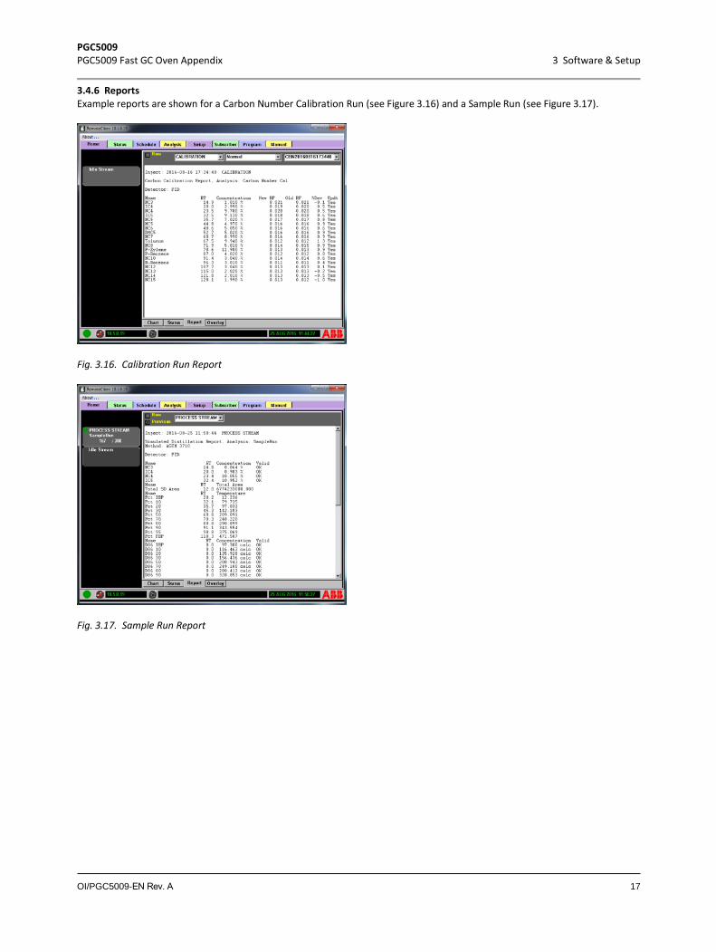
3.4.5 Schedule As with other applications of the PGC5000, Streams and Analyses are coupled in the Schedule. Typically, Calibration Runs and Blank Runs are run on demand (see Figure 3.14), where Sample Runs (and optionally, Validation Runs) may be run continuously from the Step Table (see Figure 3.15).
Fig. 3.14. Calibration Run Example
Fig. 3.15. Sample Run Example
PGC5009 PGC5009 Fast GC Oven Appendix 3 Software & Setup
OI/PGC5009-EN Rev. A 17
3.4.6 Reports Example reports are shown for a Carbon Number Calibration Run (see Figure 3.16) and a Sample Run (see Figure 3.17).
Fig. 3.16. Calibration Run Report
Fig. 3.17. Sample Run Report
PGC5009 PGC5009 Fast GC Oven Appendix 4 Technical description
OI/PGC5009-EN Rev. A 18
4 Technical description
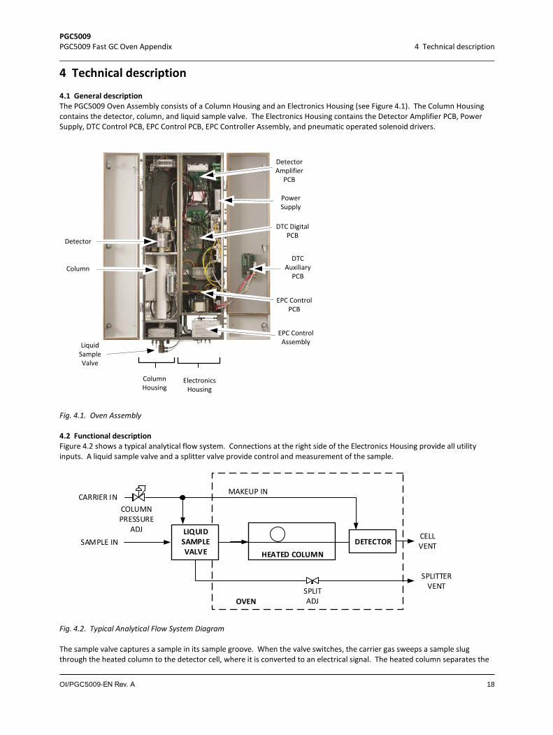
4.1 General description The PGC5009 Oven Assembly consists of a Column Housing and an Electronics Housing (see Figure 4.1). The Column Housing contains the detector, column, and liquid sample valve. The Electronics Housing contains the Detector Amplifier PCB, Power Supply, DTC Control PCB, EPC Control PCB, EPC Controller Assembly, and pneumatic operated solenoid drivers.
Detector
Column
LiquidSampleValve
ColumnHousing
ElectronicsHousing
DTC DigitalPCB
EPC ControlAssembly
EPC ControlPCB
DetectorAmplifier
PCB
PowerSupply
DTC Auxiliary
PCB
Fig. 4.1. Oven Assembly
4.2 Functional description Figure 4.2 shows a typical analytical flow system. Connections at the right side of the Electronics Housing provide all utility inputs. A liquid sample valve and a splitter valve provide control and measurement of the sample.
SAMPLE INHEATED COLUMN
SPLITADJ
CELLVENTDETECTOR
CARRIER IN
OVEN
COLUMNPRESSURE
ADJ LIQUIDSAMPLEVALVE
MAKEUP IN
SPLITTERVENT
Fig. 4.2. Typical Analytical Flow System Diagram
The sample valve captures a sample in its sample groove. When the valve switches, the carrier gas sweeps a sample slug through the heated column to the detector cell, where it is converted to an electrical signal. The heated column separates the
PGC5009 PGC5009 Fast GC Oven Appendix 4 Technical description
OI/PGC5009-EN Rev. A 19
components to be measured, which elute sequentially. The electronic output signal from the detector represents the components inputs proportionally.
The carrier gas has two purposes: to purge the column and cell prior to introducing a sample, and to sweep the sample into the detector cell. An externally mounted pressure regulator and gauge regulate the input flow.
The sample system, together with the Master Controller, controls the calibration sample input. The sample system flow and pressure control depend on the sample system configuration.
Since all other functions of the Fast GC are same as for the Standard PGC5000, refer to the PGC5000 Operations Manual for this information.
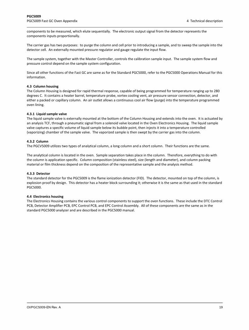
4.3 Column housing The Column Housing is designed for rapid thermal response, capable of being programmed for temperature ranging up to 280 degrees C. It contains a heater barrel, temperature probe, vortex cooling vent, air pressure sensor connection, detector, and either a packed or capillary column. An air outlet allows a continuous cool air flow (purge) into the temperature programmed oven lining.
4.3.1 Liquid sample valve The liquid sample valve is externally mounted at the bottom of the Column Housing and extends into the oven. It is actuated by an analysis TCF, through a pneumatic signal from a solenoid valve located in the Oven Electronics Housing. The liquid sample valve captures a specific volume of liquid sample below its bubble point, then injects it into a temperature controlled (vaporizing) chamber of the sample valve. The vaporized sample is then swept by the carrier gas into the column.
4.3.2 Column The PGCV5009 utilizes two types of analytical column, a long column and a short column. Their functions are the same.
The analytical column is located in the oven. Sample separation takes place in the column. Therefore, everything to do with the column is application specific. Column composition (stainless steel), size (length and diameter), and column packing material or film thickness depend on the composition of the representative sample and the analysis method.
4.3.3 Detector The standard detector for the PGC5009 is the flame ionization detector (FID). The detector, mounted on top of the column, is explosion proof by design. This detector has a heater block surrounding it; otherwise it is the same as that used in the standard PGC5000.
4.4 Electronics housing The Electronics Housing contains the various control components to support the oven functions. These include the DTC Control PCB, Detector Amplifier PCB, EPC Control PCB, and EPC Control Assembly. All of these components are the same as in the standard PGC5000 analyzer and are described in the PGC5000 manual.

PGC5009 PGC5009 Fast GC Oven Appendix 5 Maintenance and repair
OI/PGC5009-EN Rev. A 20
5 Maintenance and repair
5.1 Maintenance procedures See the PGC5000 Service Manual (SI/PGC5000/GEN2) for all maintenance procedures.
5.2 FID repair
This repair should only be attempted by people who are properly trained and possess the expertise for this repair.
Before disposing of any residual insulating materials, ensure that disposal methods comply with all applicable regulatory restrictions.
This procedure provides the extra steps required to access the detector components in an insulated FID assembly. It supplements the procedure described in the SI/PGC5000/GEN2. Refer to Figure 5.1 for FID component location.
Detector
HeaterBlock
Insulation
Fig. 5.1. FID with Heater Block
5.2.1 Removing the insulation and heater block
It is the customer’s responsibility to ensure that the area is safe and hazard-free, and will remain so the entire time the analyzer is open. This responsibility includes ensuring adequate ventilation in analyzer shelter and obtaining proper work permits, etc.
See “AIR PURGING” in the Operations Manual (OI/PGC5000/GEN2) for the X Purge override function. Do not perform override until you have read this material completely and you understand and can perform the procedure properly.
The thermocouple, polarizer and igniter assembly elements are fragile and can be easily damaged if not handled with extreme care. Do not touch the end of the elements.
Caution should be used when working with the soldering iron. The soldering iron, melted solder and heated wiring can cause severe burns. Safety glasses and protective gloves should be used to protect against hot molten solder and hot surfaces. Personal protective equipment such as goggles, face shield, lab coat and rubber gloves should be used while cleaning with solvents such as acetone. Cleaning with solvents should be done in a well-ventilated area.
1. If power is applied to the analyzer, turn it off.2. Turn off oven air and allow all temperature zones to cool. 3. Turn off carrier and other gases, as applicable.
PGC5009 PGC5009 Fast GC Oven Appendix 5 Maintenance and repair
OI/PGC5009-EN Rev. A 21
4. Open the Column Housing. 5. Remove the three screws securing the detector assembly, using a 9/64-inch hex key wrench or ball driver.6. Rotate the detector cover latch counterclockwise until it is freed from the detector body.7. Slide the detector can assembly from the detector heater housing and retain it for later use.8. Remove the insulation from the detector heater housing and retain it for later use. 9. Position the wiring and capillary tubing such that the detector heater housing can be lifted from the detector base up over
the detector. 10. Lift the detector housing off and retain it for later use.
5.2.2 Replacing FID components Refer to the Service Manual (SI/PGC5000/GEN2) for repair and replacement of the various FID components.
Any time the FID is disassembled and any O-rings removed, you must install new O-rings. Do NOT re-use O-rings.
5.2.3 Installing the insulation and heater block 1. Set the detector housing over the detector2. Insert the insulation around the detector housing.3. Slide the detector can assembly onto the detector heater housing. 4. Rotate the detector can assembly clockwise until it is securely in place.5. Insert and tighten the three screws securing the detector can assembly. 6. Close the Column Housing.
5.3 Column replacement
It is the customer’s responsibility to ensure that the area is safe and hazard-free, and will remain so the entire time the analyzer is open. This responsibility includes ensuring adequate ventilation in analyzer shelter and obtaining proper work permits, etc.
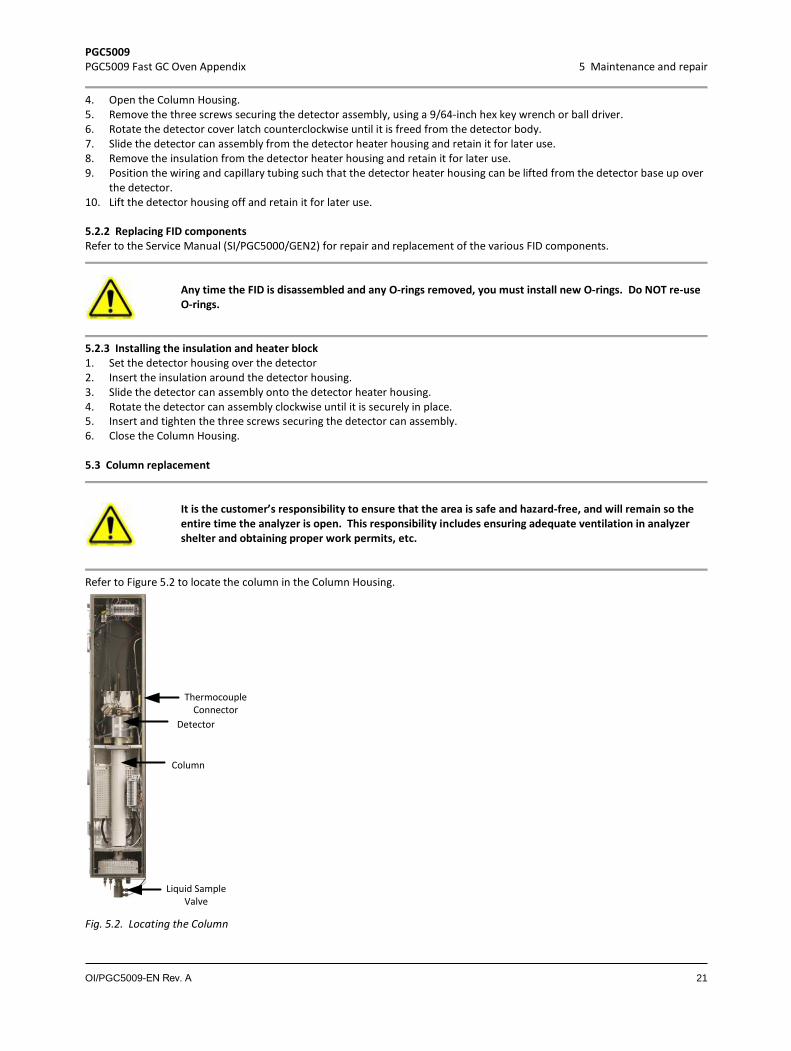
Refer to Figure 5.2 to locate the column in the Column Housing.
Detector
Column
Liquid SampleValve
ThermocoupleConnector
Fig. 5.2. Locating the Column
PGC5009 PGC5009 Fast GC Oven Appendix 5 Maintenance and repair
OI/PGC5009-EN Rev. A 22
5.3.1 Removing the column 1. If the analyzer is running and the column is to be replaced, stop the analyzer at the end of an analysis.2. Remove power from the analyzer. 3. Shut off all gases to the analyzer.
Allow the heated components to cool down to room temperature before opening the Oven Compartment.
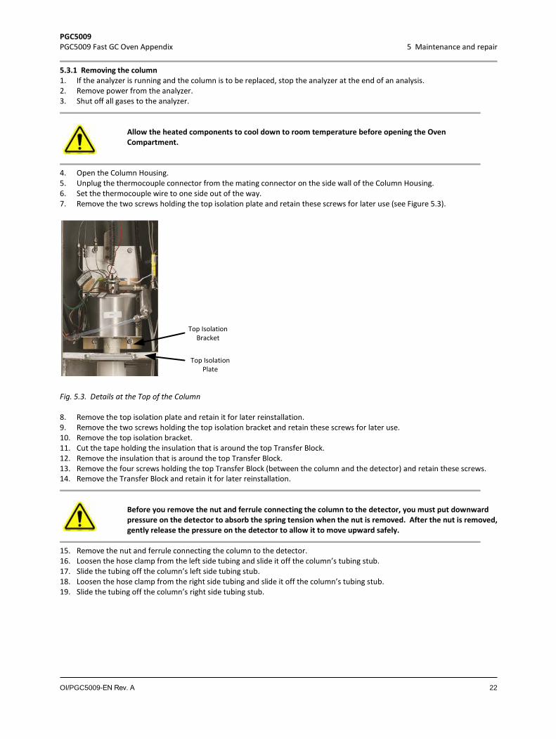
4. Open the Column Housing. 5. Unplug the thermocouple connector from the mating connector on the side wall of the Column Housing. 6. Set the thermocouple wire to one side out of the way.7. Remove the two screws holding the top isolation plate and retain these screws for later use (see Figure 5.3).
Top IsolationPlate
Top IsolationBracket
Fig. 5.3. Details at the Top of the Column
8. Remove the top isolation plate and retain it for later reinstallation. 9. Remove the two screws holding the top isolation bracket and retain these screws for later use.10. Remove the top isolation bracket. 11. Cut the tape holding the insulation that is around the top Transfer Block.12. Remove the insulation that is around the top Transfer Block.13. Remove the four screws holding the top Transfer Block (between the column and the detector) and retain these screws.14. Remove the Transfer Block and retain it for later reinstallation.
Before you remove the nut and ferrule connecting the column to the detector, you must put downward pressure on the detector to absorb the spring tension when the nut is removed. After the nut is removed, gently release the pressure on the detector to allow it to move upward safely.
15. Remove the nut and ferrule connecting the column to the detector.16. Loosen the hose clamp from the left side tubing and slide it off the column’s tubing stub.17. Slide the tubing off the column’s left side tubing stub. 18. Loosen the hose clamp from the right side tubing and slide it off the column’s tubing stub. 19. Slide the tubing off the column’s right side tubing stub.

PGC5009 PGC5009 Fast GC Oven Appendix 5 Maintenance and repair
OI/PGC5009-EN Rev. A 23
20. Remove the two screws holding the bottom isolation plate and retain these screws for later use (see Figure 5.4).
Bottom Isolation Plate
Fig. 5.4. Details at the Bottom of the Column
21. Remove the bottom isolation plate and retain it for later reinstallation. 22. Disconnect the white wire from the bottom of the column (retain the nuts and washers). Use a backup wrench to ensure
the column does not twist. 23. Cut the tape holding the insulation that is around the bottom Transfer Block, being careful not to damage the LSV wiring. 24. Remove the insulation that is around the bottom Transfer Block.25. Remove the backing nut from the stud that held the white wire.26. Remove the four screws holding the bottom Transfer Block (between the column and the liquid sample valve) and retain
these screws for later use. 27. Remove the front half of the Transfer Block and retain it for later reinstallation; if possible, leave the back half of the
Transfer Block in place to facilitate column installation. 28. Remove the nut and ferrule connecting the column to the liquid sample valve.29. Carefully remove the column from the analyzer.
5.3.2 Installing the column Install the new column with the curved tube stub ends at the bottom of the column. 1. Using an ohmmeter, check the resistance across the thermocouple connector. For the short column it should read 55 to
65 ohms; for the long column it should read 70 to 80 ohms. 2. Inspect the lower column end (with the curved tube stub ends) to ensure the column is straight.3. Place a nut and ferrule on the bottom end of the column.
The bottom Transfer Block has a notch at one end of each block half. The front half of the bottom Transfer Block has a hole for accessing the stud that holds the white wire.
3. If the back half of the bottom Transfer Block was removed, re-install it, making sure the notch is at the bottom of the block.
4. Place the end of the column into the top of the liquid sample valve, carefully seating the column in the groove in the back half of the Transfer Block.
When tightening the nut connecting the column to the liquid sample valve be careful not to rotate column, as that may damage the thermocouple wiring.
5. Tighten the 1/8-inch nut connecting the column to the liquid sample valve.6. Attach the front half of the bottom Transfer Block. 7. Insert the four screws removed earlier into the bottom Transfer Block, finger tight.8. After all four screws have been installed, tighten them.

PGC5009 PGC5009 Fast GC Oven Appendix 5 Maintenance and repair
OI/PGC5009-EN Rev. A 24
The column connection to the LSV must not be at ground (0 ohms). If it is grounded, remove the column and verify the connection.
9. Place a nut and ferrule on the top end of the column.
When tightening the nut connecting the column to the detector, be careful not to rotate column, as that may damage the thermocouple wiring.
10. Push the detector down to the column, place the top of the column in the detector and secure the nut. 11. Attach the top Transfer Block between the detector and the column.12. Insert the four screws removed earlier into the bottom Transfer Block, finger tight.13. After all four screws have been installed, tighten them.14. Place a ceramic sleeve on the top wire connector (there is no wire at this location) and place a nut to hold the ceramic
sleeve in place, finger tight. 15. Reinstall the insulation around the top Transfer Block.16. Install two strips of fiberglass tape around the insulation, one near the top of the insulation and the other near the
bottom. 17. Install the top isolation bracket and secure it with the two screws removed earlier.18. Install the top isolation plate and secure it with the two screws removed earlier.19. Slide two hose clamps over the ends of the tubing coming from the Heater Enclosure.20. Slide the left side tubing over the left side tube stub on the bottom of the column and secure with the hose clamp.21. Slide the thermocouple wire into the right side rubber tubing at least one inch. 22. Slide the right side tubing over the right tube stub on the bottom of the column, making sure the thermocouple is into the
rubber tubing about one inch beyond the metal tube stub.23. Secure the rubber tubing to the metal tube stub with the hose clamp.24. Install the ceramic sleeve and backing nut to the stud at the bottom of the column, setting the nut finger tight.25. Reinstall a washer and the white wire to the bottom of the column. 26. Install the remaining washer and nut and washer removed earlier. Use a backup wrench to ensure the column does not
twist. 27. Reinstall the insulation around the bottom Transfer Block.28. Install two strips of fiberglass tape around the insulation, one near the top of the insulation and the other near the
bottom. 29. Install the bottom isolation plate and secure it with the two screws removed earlier.30. Insert the thermocouple connector to the mating connector on the side wall of the Column Housing. 31. Close the Column Housing.
5.4 Liquid sample valve repair
5.4.1 Removing the LSV 1. Stop the analysis at the end of a cycle. 2. Turn off power to the analyzer. 3. Allow the heated components to cool down to room temperature. 4. Turn off carrier, sample, and air to the analyzer. 5. Open the Column Housing. 6. Label all tubing connections to the Liquid Sample Valve.7. Disconnect all tubing from the Liquid Sample Valve.8. Disconnect the LSV cable at the terminal block. 9. Mark the analyzer and flange to ensure the flange is reinstalled in the correct orientation. 10. Remove the four screws holding the flange to the side of the analyzer. 11. Remove the LSV from the analyzer, being careful when routing the LSV cable. The insulation and insulation retainer may
move during LSV removal; retain them for later installation.12. If you are repairing the LSV, remove it to the workbench.
PGC5009 PGC5009 Fast GC Oven Appendix 5 Maintenance and repair
OI/PGC5009-EN Rev. A 25
5.4.2 Repairing the LSV See the PGC5000 Service Manual (SI/PGC5000/GEN2) for repair procedures.
5.4.3 Installing the LSV 1. Open the Column Housing. 2. Route the LSV cable through the hole on the left side of the bottom isolation bracket.3. Install the LSV on the analyzer, making sure the insulation and insulation retainer are in the proper location around the
vaporizer. 4. Orient the flange so that the marks made at LSV removal are lined up. This should have the sample chamber vertical with
the air connections at the top of the valve and the connection of the vaporizer chamber at the top. 5. Install the four screws holding the flange to the side of the analyzer and tighten the screws. 6. Reconnect all tubing on the Liquid Sample Valve.7. Connect the LSV cable to the terminal block.8. Close the Column Housing.

PGC5009 PGC5009 Fast GC Oven Appendix 6 Replacement parts
OI/PGC5009-EN Rev. A 26
6 Replacement parts
6.1 Ordering information The replacement parts listed in this section supplement those contained in the SI/PGC5000/GEN2. For detailed information on ordering replacement parts, see SI/PGC5000/GEN2, or contact ABB Support
Since the particular application defines the component parts specific to any given system, please refer to the “Recommended Spare Parts Lists” in the analyzer’s Data Package to obtain the full and correct part number for the desired part or assembly.
6.2 Oven assembly (see Figure 6.1).
Description Part Number Flame Ionization Detector (FID) with Heater Block 845A062-1 Liquid Sample Valve 845A063-1 Packed Column Assembly 845Z001-1 DTC Digital PCB 852A028-2 DTC Auxiliary PCB 852A029-1 Detector Amplifier PCB 851A094-_ Power Supply 857Z035-2 EPC Control PCB 852A024-_ EPC Control Assembly
Detector
Column
LiquidSampleValve
ColumnHousing
ElectronicsHousing
DTC DigitalPCB
EPC ControlAssembly
EPC ControlPCB
DetectorAmplifier
PCB
PowerSupply
DTC Auxiliary
PCB
Fig. 6.1. Oven Assembly
PGC5009 PGC5009 Fast GC Oven Appendix Notes
OI/PGC5009-EN Rev. A 27
NOTES

OI/
PG
C50
09-
EN
Rev
. A
06.
2018
—We reserve the right to make technical changes or modify the contents of this document without prior notice. With regard to purchase orders, the agreed particulars shall prevail. ABB does not accept any responsibility whatsoever for potential errors or possible lack of information in this document.We reserve all rights in this document and in the subject matter and illustrations contained therein. Any reproduction, disclosure to third parties or utilization of its contents – in whole or in parts – is forbidden without prior written consent of ABB. © ABB 2018
—ABB Inc. Measurement & Analytics3567 Jefferson Street N Lewisburg, WV 24901USA Tel: +1 304 647 4358 Fax: +1 304 645 4236Mail: [email protected]
abb.com/measurement