
Aalborg Universitet Optimal Planning and Operation...
6
Aalborg Universitet Optimal Planning and Operation Management of a Ship Electrical Power System with Energy Storage System Anvari-Moghaddam, Amjad; Dragicevic, Tomislav; Meng, Lexuan; Sun, Bo; Guerrero, Josep M. Published in: Proceedings of 42nd Annual Conference of the IEEE Industrial Electronics Society (IECON), 2016 DOI (link to publication from Publisher): 10.1109/IECON.2016.7793272 Publication date: 2016 Document Version Accepted author manuscript, peer reviewed version Link to publication from Aalborg University Citation for published version (APA): Anvari-Moghaddam, A., Dragicevic, T., Meng, L., Sun, B., & Guerrero, J. M. (2016). Optimal Planning and Operation Management of a Ship Electrical Power System with Energy Storage System. In Proceedings of 42nd Annual Conference of the IEEE Industrial Electronics Society (IECON), 2016 (pp. 2095 - 2099). IEEE Press. DOI: 10.1109/IECON.2016.7793272 General rights Copyright and moral rights for the publications made accessible in the public portal are retained by the authors and/or other copyright owners and it is a condition of accessing publications that users recognise and abide by the legal requirements associated with these rights. ? Users may download and print one copy of any publication from the public portal for the purpose of private study or research. ? You may not further distribute the material or use it for any profit-making activity or commercial gain ? You may freely distribute the URL identifying the publication in the public portal ? Take down policy If you believe that this document breaches copyright please contact us at [email protected] providing details, and we will remove access to the work immediately and investigate your claim. Downloaded from vbn.aau.dk on: juli 30, 2018
Transcript of Aalborg Universitet Optimal Planning and Operation...

Aalborg Universitet
Optimal Planning and Operation Management of a Ship Electrical Power System withEnergy Storage SystemAnvari-Moghaddam, Amjad; Dragicevic, Tomislav; Meng, Lexuan; Sun, Bo; Guerrero, JosepM.Published in:Proceedings of 42nd Annual Conference of the IEEE Industrial Electronics Society (IECON), 2016
DOI (link to publication from Publisher):10.1109/IECON.2016.7793272
Publication date:2016
Document VersionAccepted author manuscript, peer reviewed version
Link to publication from Aalborg University
Citation for published version (APA):Anvari-Moghaddam, A., Dragicevic, T., Meng, L., Sun, B., & Guerrero, J. M. (2016). Optimal Planning andOperation Management of a Ship Electrical Power System with Energy Storage System. In Proceedings of 42ndAnnual Conference of the IEEE Industrial Electronics Society (IECON), 2016 (pp. 2095 - 2099). IEEE Press.DOI: 10.1109/IECON.2016.7793272
General rightsCopyright and moral rights for the publications made accessible in the public portal are retained by the authors and/or other copyright ownersand it is a condition of accessing publications that users recognise and abide by the legal requirements associated with these rights.
? Users may download and print one copy of any publication from the public portal for the purpose of private study or research. ? You may not further distribute the material or use it for any profit-making activity or commercial gain ? You may freely distribute the URL identifying the publication in the public portal ?
Take down policyIf you believe that this document breaches copyright please contact us at [email protected] providing details, and we will remove access tothe work immediately and investigate your claim.
Downloaded from vbn.aau.dk on: juli 30, 2018

Optimal Planning and Operation Management of a Ship
Electrical Power System with Energy Storage System
Amjad Anvari-Moghaddam, Tomislav Dragicevic, Lexuan Meng, Bo Sun, and Josep M. Guerrero Department of Energy Technology, Aalborg University
Aalborg, Denmark
Email: [email protected]
Abstract— Next generation power management at all scales
is highly relying on the efficient scheduling and operation of
different energy sources to maximize efficiency and utility. The
ability to schedule and modulate the energy storage options
within energy systems can also lead to more efficient use of the
generating units. This optimal planning and operation
management strategy becomes increasingly important for off-
grid systems that operate independently of the main utility, such
as microgrids or power systems on marine vessels. This work
extends the principles of optimal planning and economic
dispatch problems to shipboard systems where some means of
generation and storage are also schedulable. First, the question
of whether or how much energy storage to include into the
system is addressed. Both the storage power rating in MW and
the capacity in MWh are optimized. Then, optimal operating
strategy for the proposed plan is derived based on the solution
from a mixed-integer nonlinear programming (MINLP)
problem. Simulation results showed that including well-sized
energy storage options together with optimal operation
management of generating units can improve the economic
operation of the test system while meeting the system’s
constraints.
Keywords— Shipboard power system, energy management,
energy storage, optimization.
I. INTRODUCTION
The need for more efficient offshore systems together with the motivations for the exploitation of advanced power technologies have been the incentive for turning all energy subsystems aboard into more efficient and greener ones. In this context, optimal power management is becoming of great importance in such systems due to its direct impact on efficiency enhancement of ships. With an optimal power management strategy the best out of each unit can be taken and dispatched in a way to satisfy any technical problems [1]. However, a reliable supply of electrical power is essential in any shipboard system. A drill-ship is not immune to this concern. Because of the dynamically positioned (DP) drill-ship, variable speed drives are employed for the ship’spropulsion and drilling systems and a dependable power source is needed for the successful operation of both systems. For these reasons, the use of energy storage system (ESS) is
one of the most effective solutions for ensuring the reliability and power quality of a drill-ship power system and favors the increased penetration of other means of distributed generation [2]. Moreover, ESS can highly contribute to load demand management and generally to the global energy management of the ship with possible reduction of prime movers which in turn reduces operation cost [3].
In choosing to install an ESS, two important economic factors should be taken into account: feasibility of installing any ESS and sizing of the system in case of feasibility. Sizing means both the amount of energy that will be able to be stored as well as the limit of power that will be able to be put into or taken out of storage at any given time. Regarding the aforementioned points, a number of studies have investigated optimal power arrangements on ships [4]-[15]. For example a hybrid battery/diesel generation system has been explored for ship crane operations in [6] where an auxiliary power system, including diesel engines, battery energy storage systems based on lithium-ion technology, cranes and ship hotel consumers were also taken into account. ESSs have been utilized in converting the bulk carriers to all-electric ships in [7] for minimizing fuel consumption. In the same work, the engine loading levels and energy demand were calculated, and sizing of suitable propulsion system was proposed based on the potential for fuel savings. Merits of a hybrid energy system with flywheel energy storage have been analyzed in [8] from economic/environmental viewpoints. The analysis were mainly focused on the impact of utilizing flywheel energy storage systems on power generation, energy cost, and net present cost for certain configurations of hybrid system. An optimal power management strategy for a standalone hybrid system under uncertainties has been proposed in [9] to minimize the levelized cost of energy and maximize reliability. A robust method of design for wind-PV-diesel configuration was also developed considering uncertain parameters as well as minimal number of probabilistic analysis. An optimal unit sizing method for a stand-alone system has also been discussed in [10] where a metaheuristic approach was utilized to solve the optimal sizing problem with regard to different objectives such as minimization of pollutant emissions, minimization of degradation cost as well as maximization of green energy source penetration.
In this paper, an effective optimization model is presented for optimal sizing of ESS and economic dispatch of controllable units for a typical drill-ship’spowersystem.Themodel is formulated as a single-objective constrained mixed-integer nonlinear programming (MINLP) optimization problem. The primary variables include the energy and power capacities (EESS,max, PESS,max) of the ESS (which is a flywheel in this special case) as well as the optimal power outputs of other dispatchable units (PDG,i) for a given time period. The objective function is also defined as the minimization of the sum of operating costs and appropriately annualized installation costs.
The rest of the paper is organized as follows: Section II deals with optimal planning and economic dispatch problem of a drill-ship’spowersystem. The case studies and simulation results are provided in Section III, whereas Section IV draws thepaper’sconclusions.
II. PROBLEM FORMULATION
Optimal planning and economic dispatch of a drill-ship’spower system for a specific system load is formulated as follows:
A. Chronological Load Curve
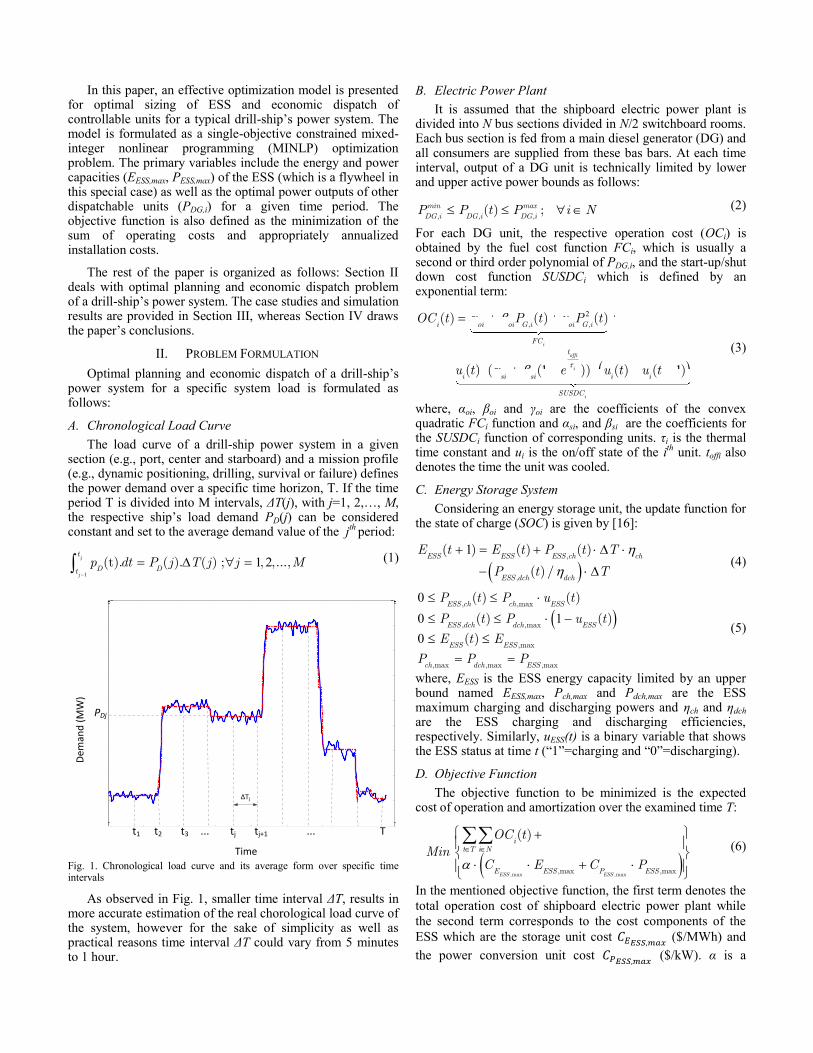
The load curve of a drill-ship power system in a given section (e.g., port, center and starboard) and a mission profile (e.g., dynamic positioning, drilling, survival or failure) defines the power demand over a specific time horizon, T. If the time period T is divided into M intervals, ΔT(j), with j=1,2,…,M, the respective ship’s load demand PD(j) can be considered constant and set to the average demand value of the j
th period:
1
1 2(t). ( ). ( ) ; , ,...,j
j
t
D Dtp dt P j T j j M
(1)
Fig. 1. Chronological load curve and its average form over specific time intervals
As observed in Fig. 1, smaller time interval ΔT, results in more accurate estimation of the real chorological load curve of the system, however for the sake of simplicity as well as practical reasons time interval ΔT could vary from 5 minutes to 1 hour.
B. Electric Power Plant
It is assumed that the shipboard electric power plant is divided into N bus sections divided in N/2 switchboard rooms. Each bus section is fed from a main diesel generator (DG) and all consumers are supplied from these bas bars. At each time interval, output of a DG unit is technically limited by lower and upper active power bounds as follows:
, , ,( ) ;min max
DG i DG i DG iP P t P i N (2)
For each DG unit, the respective operation cost (OCi) is obtained by the fuel cost function FCi, which is usually a second or third order polynomial of PDG,i, and the start-up/shut down cost function SUSDCi which is defined by an exponential term:
2
1 1
, ,( ) ( ) ( )
( ) ( ( )) ( ) ( )
i
offi
i
i
i oi oi G i oi G i
FC
t
i si si i i
SUSDC
OC t P t P t
u t e u t u t (3)
where, αoi, βoi and γoi are the coefficients of the convex quadratic FCi function and αsi, and βsi are the coefficients for the SUSDCi function of corresponding units. τi is the thermal time constant and ui is the on/off state of the i
th unit. toffi also
denotes the time the unit was cooled.
C. Energy Storage System
Considering an energy storage unit, the update function for the state of charge (SOC) is given by [16]:
1
,
,
( ) ( ) ( )
( ) /ESS ESS ESS ch ch
ESS dch dch
E t E t P t T
P t T (4)
0
0 1
0
, ,max
, ,max
,max
,max ,max ,max
( ) ( )
( ) ( )
( )
ESS ch ch ESS
ESS dch dch ESS
ESS ESS
ch dch ESS
P t P u t
P t P u t
E t E
P P P
(5)
where, EESS is the ESS energy capacity limited by an upper bound named EESS,max, Pch,max and Pdch,max are the ESS maximum charging and discharging powers and ηch and ηdch are the ESS charging and discharging efficiencies, respectively. Similarly, uESS(t) is a binary variable that shows the ESS status at time t (“1”=chargingand“0”=discharging).
D. Objective Function
The objective function to be minimized is the expected cost of operation and amortization over the examined time T:
,max ,max,max ,max
( )
ESS ESS
it T i N
E ESS P ESS
OC tMin
C E C P (6)
In the mentioned objective function, the first term denotes the
total operation cost of shipboard electric power plant while
the second term corresponds to the cost components of the
ESS which are the storage unit cost ($/MWh) and
the power conversion unit cost ($/kW). α is a
0 10 20 30 40 50 60 70 803
3.2
3.4
3.6
3.8
4
4.2
4.4
4.6
4.8
Time(Sec)
Pow
er
[MW
]
t1 t2 t3 tj tj+1 T... ...
ΔTj
Time
Dem
and
(M
W)
PDj

dimensionless scaling parameter used to express the cost of
the ESS on a predefined time interval basis.
E. Constraints
The proposed optimization problem should be solved subject to the following equality constraint and those previously mentioned for different components:
, , ,( ) ( ) ( )
( ) ( ) ;
DG i ESS dch ESS chi N
D OL
P t P t P t
P t P t t T (7)
where POL is the ohmic losses of the system that can be safely assumed negligible, as the onboard distribution network between generators and loads is not extended but limited in a few meters of three phase cables and electric bus-bars.
III. SIMULATION RESULTS
The simulation example considers one of the variations of a case study in [2] where a typical drill-ship should be operated economically in a steady-state environment. The shipboard power plant is equipped with 6 diesel generators of nominal active power of 7.0 MW connected to 11 kV main switchboards (SWBDs). All SWBDs can be interconnected by
bus tiebreakers and operated in different configurations (e.g., three-split, two-split, and close-ring) depending on the situation at that time. Supply and demand sides’ setting anddistribution are illustrated in Fig. 2, and are characterized as follows:
There are three main 11-kV buses/SWBDs, each
with two DGs having circuit breakers that allow
them to be connected or disconnected. In this study,
DGs are operated in close-ring mode with the fuel
cost functions and technical constraints as shown in
Table 1.
Table 1. Electric power plant specifications
DGi αoi
(¢) βoi
(¢/kW) γoi
(¢/kW2) αsi
(¢) βsi
(¢) ,
min
DG iP
(MW)
,
max
DG iP
(MW)
Plant
#1
1 450 10 13.5 10 20 0 7
2 430 12 13.0 12 24 0 7
Plant
#2
3 460 12 13.5 12 18 0 7
4 390 58 5.6 11 19 0 7
Plant #3
5 370 57 5.4 11 21 0 7
6 340 52 5.2 12 20 0 7
Fig. 2. Configuration of simulated drilling vessel
DCDC
ACDC
Eco
no
mic
Po
we
r D
isp
atch
Energy Storage System
Drilling Drive
AzimuthThruster
Electric Power Plant
DC Load
AC Load
System Load
Mission Profile
Shipboard Section
Plant Configuration
Units Specifications

There are six azimuth thrusters with nominal power
of 5.5 MW arranged in a standard geometric layout
(two for each main SWBD),
There are several feeders extended from the main
SWBDs providing needed power to topsides through
11kV/690V or 11kV/440V transformers,
There is an ESS connected to a DC bus which
regulates any excess or deficit produced power and
contributes in energy management of the drilling
vessel,
The consumers are mainly include drilling drives,
active heave draw-works drives, cement pumps,
firewater pumps, mud pumps and top drives which
form the typical load demand of the drill-ship
presented by Fig. 3.
Fig. 3. Electrical load demand of the drill-ship for several mission profiles
(Case A- normal DP & normal drilling; Case B- heavy DP & normal drilling,
Case C- heavy DP & heavy drilling; and Case D- survival)
It should be mentioned that all of the algorithms and simulations were executed on a PC with an Intel i5-2430M chip running Windows 7(64 bit) with GAMS and Cplex/Dicopt solvers. Since GAMS is a high-level modeling system designed for solving linear, non-linear, and mixed-integer optimization problems, it was selected as the main optimization engine. Also, Cplex/Dicopt solvers are utilized to allow users to combine the high level modeling capabilities of GAMS with the power of such optimizers [17].
The primary solution results obtained from the solution of the sizing optimization problem are the values for the energy and power capacities of the ESS. To this end, approximate costs for installing ESS based on flywheel technology are considered to be 1600$/kWh and 600$/kW, respectively. By solving the proposed optimization problem, the optimal value for PESS,max was found to be 1.407 MW and the optimal value for EESS,max was found to be 2.579 MWh. Simulation results for optimal dispatch of generation units in different power plants are shown in Fig. 4 considering the given load profile. Optimal dispatch of designed ESS under the defined mission profile is also shown in Fig. 5.
(a) Plant #1- DG 1&2
(b) Plant #2- DG 3&4
(C) Plant #3- DG 5&6
Fig. 4. Economic dispatch of DGs (in MW) during 5-minute intervals (Ti) for
the given load profile
As can be observed from the computer simulations, the proposed optimization model not only shares the load among thegenerationunitsinawaytomeetthesystem’sconstraints,but also dispatches units in an economic way to meet the system’sobjective.Totaloperatingcostoftheelectricpowerplant for the examined period is calculated as 454.65$ which is 13.5% lower than the cost of operation for a plan of action where equal load sharing is the point of interest. Moreover, it can be understood from the operation of the storage unit that during off-peak times (e.g., 0-15 min. in normal DP and drilling mode), the storage unit mainly operates in charging mode to increase the back-up power for critical periods. As the net load rises through the heavy DP or drilling times, the ESS is switched into discharge mode and shaves the peaks off of
0 5 10 15 20 25 30 35 40 45 50 55 60 65 70 75 806
7
8
9
10
11
12
13
14
15
Time (minutes)
Pow
er
[MW
]
Total Load
Measured Load
Average Demand
Case A
Case B
Case C
Case D
4.36
5.51
5.51
5.51
5.36
5.51 5.36 5.36
5.34
5.63
5.51
5.51
5.51
4.733.56
T1 T2 T3 T4 T5 T6 T7 T8 T9 T10 T11 T12 T13 T14 T15

the load giving the DGs smoother operation and better performance.
Fig. 5. Optimal operation of ESS
IV. CONCLUSION
In this paper, optimal energy storage system sizing together with economic dispatch of a drillship power system was analyzed. A power management optimization model was proposed so that ship operation cost was minimized while system’s technical and operational constraints were notviolated. Compared to the conventional approaches, the proposed method not only addressed the question of how much energy storage to install, but also provided insight into the scheduling of different electric power plants in a drilling vessel thorough various loading levels and mission profiles.
REFERENCES
[1] Kanellos, F.D., “Optimal power management with GHG emissions
limitation in all-electric ship power systems comprising energy storage
systems,” IEEE Trans. Power Syst., vol.29, no.1, pp.330-339, Jan. 2014.
[2] Johansen, T.A.; Bo, T.I.; Mathiesen, E.; Veksler, A.; Sorensen, A.J.,
“Dynamic positioning system as dynamic energy storage on diesel-electricships,”IEEE Trans. Power Syst., vol.29, no.6, pp.3086-3091,
Nov. 2014. [3] Anvari-Moghaddam, A.; Dragicevic, T.; Vasquez, J.C.; Guerrero,
J.M.,“Optimal utilization of microgrids supplemented with battery
energy storage systems in grid support applications”, 1st IEEE Int. Conf. DC Microgrids, Atlanta, June 7-10, 2015.
[4] Yan,C.; Venayagamoorthy,G.K.; Corzine,K.A., “Optimal location
and sizing of energy storage modules for a smart electric ship power system”, IEEE Symp. Comput. Intell. Appl. Smart Grid, pp. 123–30,
2011.
[5] Zahedi, B.; Norum, L.E.; Ludvigsen,K.B., “Optimized efficiency ofall-electricshipsbydchybridpowersystems”,J. Power Sources, vol.
255, pp. 341–54, 2014.
[6] Ovrum, E.; Bergh, T.F., “Modelling lithium-ion battery hybrid ship craneoperation”,Appl. Energy, vol. 152, pp.1–11, 2015.
[7] Dedes,E.K.;Hudson,D.A.;Turnock,S.R.,“Assessingthepotentialof
hybrid energy technology to reduce exhaust emissions from global shipping”,Energy Policy, vol.40, pp.204–18, 2012.
[8] Ramli, M.M.; Hiendro, A.; Twaha, S., “Economic analysis of
PV/diesel hybrid system with flywheel energy storage”, Renew. Energy, vol.78, pp. 398–405, 2015.
[9] Maheri,A.,“Multi-objective design optimization of standalone hybrid
wind-PV diesel systems under uncertainties”,Renew Energy, vol.66, pp. 650–61, 2014.
[10] Zhao,B.;Zhang,X.;Li,P.;Wang,K.;Xue,M.;Wang,C.,“Optimal
sizing, operating strategy and operational experience of a stand-alone
microgridonDongfushanIsland”Appl. Energy, vol.113, pp.1656–66,
2014. [11] Parvizimosaed, M.; Farmani, F.; Anvari-Moghaddam, A.; Rahimi-
Kian, A.; Monsef, H., “AMulti-Objective Algorithm for Sitting and
Sizing Renewable Resources in Distribution Network Considering Load Model”, J. Iranian Association of Electrical and Electronics
Engineers (IAEEE), vol. 12, no.1, pp. 1-10, 2014
[12] Anvari-Moghaddam, A.; Ghasemi, H., “Energy Management in aMicro-Grid with High Penetration of Renewable Resources
Considering Emission Constraints”, 28th International Power System
Conference(PSC’13),Tehran,Iran,Nov.4-6, 2013. [13] Glykas, A.; Papaioannou, G.; Perissakis, S., “Application and cost-
benefit analysis of solar hybrid power installation on merchant marine vessels”,Ocean Eng., vol. 37, pp.592–602, 2010.
[14] Lee, K.J.; Shin, D.S.; Lee, J.P.; Yoo, D.W.; Choi, H.K.; Kim, H.J.,
“Hybrid photovoltaic/diesel green ship operating in standalone andgrid-connected mode in South Korea – Experimental investigation”,
IEEE Veh. Power Propuls. Conf. VPPC, vol. 49, pp. 580–583, 2012.
[15] Adamo, F.; Andria, G.; Cavone, G.; De Capua, C.; Lanzolla, A.M.L.; Morello, R., “Estimation of ship emissions in the port of Taranto”,
Meas. J. Int. Meas. Confed., vol.47, pp.982–988, 2014.
[16] Anvari-Moghaddam, A.; Vasquez, J.C.; Guerrero,J.M.,“LoadShiftingControl and Management of Domestic Microgeneration Systems for
ImprovedEnergyEfficiencyandComfort”,41stAnnualConferenceof
the IEEE Industrial Electronics Society, November 9-12, Yokohama, Japan, 2015.
[17] Anvari-Moghaddam, A; Monsef, H; Rahimi-Kian, A., “OptimalSmart
Home Energy Management Considering Energy Saving and a ComfortableLifestyle”,IEEE Trans. Smart Grid, vol.6, no.1, pp. 324-
332, 2015.
0.0
0.1
0.2
0.3
0.4
0.5
0.6
0.7
-4
-2
0
2
4
6
8
10
12
14
16
1 3 5 7 9 11 13 15
SOC
(%
)
De
man
d &
ESS
Ou
tpu
t P
ow
er
(MW
)
Time Intervals
Load P_ESS SOC