
AADE-15-NTCE-38 Hydraulic Fracturing Fluid Modified with ...
Upload
phungnguyetCategory
view
221download
1
This paper was prepared for presentation at the AADE 2004 Drilling Fluids Conference, held at the Radisson Astrodome in Houston, Texas, April 6-7, 2004. This conference was sponsored by the Houston Chapter of the American Association of Drilling Engineers. The information presented in this paper does not reflect any position, claim or endorsement made or implied by the American Association of Drilling Engineers, their officers or members. Questions concerning the content of this paper should be directed to the individuals listed as author/s of this work.
Abstract
The challenges encountered while drilling the subject well demonstrate the reduction in whole mud losses typically achieved with a uniquely formulated, clay-free synthetic-based fluid (SBF). The well was located in a water depth of 3,360 ft. The total depth was 29,300 ft measured depth (MD) and 25,672 ft true vertical depth (TVD).
After displacing to the clay-free SBF, the actual whole mud losses while drilling for the entire well were 57% less than anticipated. No fluid was lost while running or cementing any of the casing strings. No barite sag was detected by modular dynamic test (MDT) logs or observation.
One of the most challenging aspects of the well was the successful running and cementing of an 11 7/8-in. liner across several massive, highly permeable sands in 5,512 ft of 14-in. wellbore with 35° deviation. Offset wells drilled with conventional SBFs encountered severe losses during similar operations.
The dramatic reduction in whole mud loss was attributed primarily to the performance of the clay-free SBF system. Organophilic clays and lignites have been eliminated from the fluid formulation. Gel strengths develop quickly and provide good suspension, but break almost instantaneously when pressure is applied, as indicated by pressure-while-drilling (PWD) logs. This case history documents the significant cost reductions related to drilling performance that can be achieved with the unique system. Introduction
Most wells drilled in Green Canyon Block 328, Gulf of Mexico (GOM), have a 15,000 ft to 20,000 ft MD, and a maximum hole angle of 35°. The plan for the Quatrain Green Canyon 382 #1 well presented several challenges not usually seen in this area: a 50° deviation, an 11,000-ft horizontal displacement, a 12 ¼-in. hole size in the production interval, and a target TVD nearly 3,000 ft deeper than the offsets (Figure 1).
As might be expected in a water depth of 3,360 ft, the margin between pore pressure and fracture gradient is relatively narrow, increasing the risk of whole mud
losses unless the equivalent circulating density (ECD) of the drilling fluid is closely managed. Most offset wells encountered significant whole mud losses while drilling, running casing, and cementing, as well as delays resulting from stuck pipe. To help minimize losses and non-productive time (NPT) on the subject well, the rheological properties of the fluid would have to remain stable over a wide range of temperatures, yet provide adequate suspension to prevent barite sag at the anticipated maximum mud weight of 14.2 lb/gal. In addition, the 12 ¼-in. hole size planned for the high-angle production interval presented a major hole-cleaning challenge.
Two key technologies were applied to help ensure the success of the drilling operation:
1. During the planning phase, the well was drilled on paper (DWOP) using a highly accurate hydraulics modeling program. The geometry, deviation, and drilling modes for each interval were carefully evaluated to help minimize ECD and optimize hole cleaning, a critical factor in this high-angle well. The hydraulics modeling program was used throughout the well construction process to help maintain optimal conditions.
2. The operator used an innovative SBF containing no organophilic clay or lignites to drill from the 20-in. casing point (±6,150 ft MD) to total depth (TD). The clay-free system is widely used on deepwater GOM wells and has demonstrated significantly reduced whole mud losses when compared to conventional SBFs (Figure 2). The reduced losses are typically attributed to lower ECDs and a stable rheological profile over the temperature ranges encountered in deeper water depths (Figure 3). No incidents of detectable barite sag have occurred with the clay-free SBF to date (Figure 4).
The operator was able to drill to 20,457 ft MD/ 18,006
ft TVD, where an 11 7/8-in. liner was run through massive loss-prone sands without any losses. The liner was cemented in the 35° angle section with only 132 bbl of
AADE-04-DF-HO-36
Case History: Zero Whole Mud Losses Achieved during Casing and Cementing Operations on Challenging Deepwater Well Drilled with Clay-Free Synthetic-Based Fluid Andy Patrickis, Murphy Exploration & Production Company; Robert Hsia, Baroid product service line, Halliburton

2 A. PATRICKIS, R. HSIA AADE-04-DF-HO-36
mud lost when the circulating pressure exceeded the formation integrity test (FIT). The final interval was drilled with a 12 1/4-in. bit to 22,744 ft and then a 10 5/8-in. bit to TD at 25,940 ft MD/22,312 ft TVD with no problems. After several days of wireline logging and sidewall coring operations, the operator ran and cemented an 8 5/8-in. production liner with no mud losses.
Well Planning
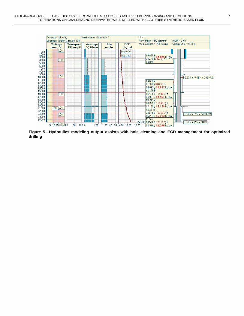
Hydraulics modeling of multiple drilling scenarios included each expected wellbore geometry, possible rates of penetration (ROP), pump output, rotary speeds, cuttings size, rheological properties, fluid compressibility, and temperature effects. Based on modeling outcomes, the operator and rig personnel could optimize drilling parameters including pump output, ROP, cuttings loading, and ECD (Figure 5). To obtain conservative predictive data and avoid stressing the wellbore, output from the riser boost pump, which can add up to 300 gal/min, was not used in the calculation. The pump rate ranges listed in Table 1 were identified in the planning stage.
After spudding the well, the operator and drilling fluids personnel continued to model existing conditions and modify operational parameters as needed. For example, any change in the bottomhole assembly (BHA) that affected the wellbore geometry was analyzed for its impact on pressure drops, ECD, and hole cleaning. The operator had to preserve a careful balance between maintaining the rheological properties required to suspend cuttings and prevent barite sag in a large, high-angle wellbore and controlling ECD within the acceptable limits identified by modeling. Minimizing surge pressures and the pressure required to break circulation after a static period also played a critical role in avoiding downhole mud losses.
Based on hydraulics modeling and PWD data obtained from numerous deepwater wells in the GOM, the operator selected an emulsion-based synthetic fluid that contains no commercial organophilic clays or lignitic materials. In addition to providing stable rheological properties at both seabed and downhole temperatures, the selected SBF appears to have lower ECDs, based on PWD data. Field observations and information provided by highly accurate hydrostatic pressure sampling tools also indicate that this particular SBF is not susceptible to sag, even after long periods out of the hole. Given the parameters for the subject well, the clay-free SBF seemed to offer the best combination of properties for a safe, cost-effective deepwater drilling operation.
Problem-Free Riserless Interval
Based on the wellbore geometry and anticipated formation pressures, the 26-in. riserless interval required a 10.5-lb/gal fluid to drill to the proposed 20-in. casing point at 6,100 ft. Using a proprietary spreadsheet to
analyze the riserless interval, the well planners determined the appropriate cut-back ratios to achieve the desired fluid densities for drilling and for the pad mud to be displaced into the well before running casing. To help ensure that the 10.5-lb/gal target density was maintained, a 16.5-lb/gal fluid would be cut back with seawater using a high-capacity vortex mixer. High-viscosity sweeps formulated with prehydrated gel and seawater were recommended to assist with hole cleaning.
Although pumping at a relatively low rate would help reduce the “pump-and-dump” loss at the seafloor, slowing the pump rate too much would jeopardize hole-cleaning efficiency. Further, maintaining the target hydrostatic pressure was crucial to reaching casing point without hole collapse or influx from shallow formations. The target flow rate for the interval was 1,300 gal/min at the anticipated 75 ft/hr ROP, but the interval was also modeled using a 1,100 gal/min flow rate to help ensure that hole cleaning would be adequate if reducing the pump output became necessary. At the lower flow rate, the calculated cuttings load was an acceptable 3.5%.
The drilling fluid was mixed and treated on-the-fly at flow rates up to 1,200 gal/min (1,700+ bbl/hr) to accommodate the 100+ ft/hr average ROP. No bit balling occurred while the 26-in. interval was drilled. At TD, the 10.5-lb/gal fluid was successfully displaced with a treated 13.5-lb/gal pad mud after a 200-bbl high-viscosity sweep was pumped. No influx of formation fluids or wellbore swelling was observed. The 20-in. casing string was run and cemented with no problems. A total of 13,396 bbl of drilling fluid was consumed during the riserless interval.
Synthetic-Based Fluid Selection
After 20-in. casing was set at 6,101 ft, the well was drilled using an SBF formulated with a blended ester-internal olefin base oil. Performance data from offset wells where this ester-blend system had been used indicated that it reduced average whole mud losses and provided improved control over ECDs. Offset PWD data also demonstrated that circulation initiation pressures are exceptionally low with the system. Almost no pressure spike occurred after static periods, as shown in the PWD log segments from various depths (Figure 6).
Barite sag prevention was another incentive for using the clay-free system. Numerous other deepwater case histories, including wells drilled by this operator, indicated that the system did not sag, nor did it require extensive conditioning before tripping out of the hole to prevent a sag incident. To help ensure that the fluid would provide the desired suspension characteristics needed to avoid barite sag at the expected downhole temperatures, samples were regularly tested for settling tendencies at a central laboratory. The results were expressed in a numerical “sag coefficient” (or “sag signature”) based on results achieved with the high-

AADE-04-DF-HO-36 CASE HISTORY: ZERO WHOLE MUD LOSSES ACHIEVED DURING CASING AND CEMENTING 3 OPERATIONS ON CHALLENGING DEEPWATER WELL DRILLED WITH CLAY-FREE SYNTHETIC-BASED FLUID
angle sag test (HAST) device.1 The ideal sag coefficient is zero; the clay-free system showed minimal sag tendency with a sag coefficient of 2.2 (Table 2). These results were duplicated in the field. While logging the well at TD, the operator ran a hydrostatic pressure sampling tool known to be accurate to 1 psi. No barite sag was detected after two separate wireline logging runs of four and five days each, respectively.
Running and Cementing 11 7/8-in. Liner across Massive Sands
One of the most potentially problematic hole sections was the 14-in. interval (14,945 to 20,457 ft), which was known to contain several massive permeable sands at 17,160 to 17,630 ft, 18,840 to 19,210 ft, and 19,340 to 19,800 ft. The active drilling fluid system was pretreated with sized calcium carbonate and a deformable, carbon-based lost-circulation additive to minimize seepage. The Tau “0” was maintained between 8.5 to 10.5 to help prevent barite sag.
The hole angle in this interval was maintained at 35°. To prevent silt build-up, weighted sweeps were typically pumped every other connection. The sweeps were built with proprietary coarse-grind barite to achieve a density of 2.0 to 3.0 lb/gal over the density of the active system. The sweep volume was calculated to cover at least 250 ft of the annulus. Pipe rotation was maintained at 100+ rpm while the sweeps were pumped to help facilitate the “jet-stream” scouring action. Each weighted sweep was completely circulated out of the wellbore with continuous pumping. If pumping is stopped while a weighted sweep is in the deviated portion of the well, most of the “fines” and cuttings captured in the sweep are redeposited, along with the barite used to build the sweep. Later in the drilling operation, the weighted sweeps were not circulated out properly and hole problems occurred as a result.
At 20,457 ft, the hole was circulated clean before pulling out to run the 11 7/8-in. liner. The SBF did not require thinning in preparation for running pipe because the gel strength of the system is robust but fragile, allowing for minimal surge pressures while still providing adequate suspension to prevent barite sag.
An optimal pipe running speed of 43 ft/min was determined by modeling the trip equivalent mud weight with hydraulics analysis software before running the liner. Both drilling fluid and cementing hydraulics were modeled and compared to help ensure that the recommended pump rates were optimized for cementing operations. The liner was run and circulated at bottom with good returns, then cemented. After drilling out, a successful 15.5-lb/gal FIT was obtained. By comparison, numerous hole problems and losses in excess of 2,000 bbl occurred on the offset wells while this interval was drilled with conventional SBF (Figure 7).
The Lower Wellbore As the hole angle approached 50°, the hydraulics
modeling and drilling parameters were constantly re-verified to help ensure that adequate hole cleaning was taking place and help minimize the risk of stuck pipe. Maintaining a rotary speed of 100+ rpm while completely circulating out each weighted sweep was critical to silt-bed removal. However, at times, the sliding operation was resumed before the sweeps reached the surface. The sliding rotary speed of 45 to 50 rpm was marginal at best for hole cleaning. The lubricity of the drilling fluid helped lower the risk of stuck pipe, but indications of silt-bed buildup in this interval were apparent.
Damage to the PDC bit and the loss of six cutters resulted in the need to sidetrack above the junk. After setting a cement plug at 22,918 ft, the operator continued drilling to TD with no further problems. After logging and taking sidewall cores for approximately nine days, the operator was able to run and cement an 8 5/8-in. liner with no mud lost while running pipe and only 30 bbl lost during the cement displacement. The consistent success of the cementing work on each casing string has been attributed to close coordination between the drilling fluids and cementing personnel and their use of proprietary modeling software to help ensure that pump rates did not put the wellbore at risk for loss of circulation.
Conclusions
Careful modeling of proposed and existing drilling parameters, including coordination with cementing specialists and the use of cementing modeling software, helped ensure that hydraulics were optimized while drilling, running casing, and cementing. As a result, mud losses were kept to a minimum, with a 3,684-bbl total loss to the formation while drilling, and less than 100 bbl lost while running casing and cementing.
The decision to use the clay-free SBF allowed the operator to reduce the risk of whole mud losses in the following ways:
Minimal pressure to initiate circulation Minimal surge pressures Comparatively low ECDs
The SBF system showed zero evidence of barite sag
on this well and others drilled by the same operator, as verified by highly accurate pressure sampling tools run during wireline logging operations.
Minimizing mud losses and associated NPT, especially evident while running and cementing the 11 7/8-in. liner with narrow clearance in the 14-in. hole, resulted in reduced drilling fluid and operational costs for the operator. Compared to offsets drilled with conventional SBF systems, the Quatrain well was drilled ±3,000 ft deeper, with a much higher angle, and with larger hole sizes, yet the drilling fluid cost was only 5%

4 A. PATRICKIS, R. HSIA AADE-04-DF-HO-36
greater on average. The two nearest offsets drilled with conventional SBF required 80 and 133 days to reach TD at 19,282 ft and 21,714 ft, respectively. The Quatrain reached TD and production pipe was successfully run and cemented at 25,940 ft in 88 days.
Acknowledgments
The authors thank Murphy Exploration & Production Company and Halliburton for permission to publish this paper.
References 1. Jamison, D. and Clements, W.: “A New Test Method
to Characterize Settling/Sag Tendencies of Drilling Fluids Used in Extended Reach Drilling,” ASME Drilling Technology Symposium, New Orleans, Louisiana, Jan. 14-18, 1990.
Table 1—Planned Pump Rate Ranges
Hole Size (in.)
Depth (ft)
Pump Output (gal/min)
26 (riserless/WBF) 3,414 to 6,150 1,088 to 1,470
20 (SBF) 6,150 to 9,160 788 to 1,179
17 (SBF) 9,160 to 14,828 967 to 1,017
14 (SBF) 14,828 to 20,457 844 to 897
12 1/4 / 10 5/8 (SBF) 20,457 to 25,940 605 to 651
Table 2— Mud Formulation and Properties with High-Angle Sag Test Results (Sag Coefficient)
Sample Mark A Clay-Free SBF mud sample, bbl 1
Temperature, °F 120
Mud wt, lb/gal 13.2
Plastic viscosity, cP 35
Yield point, lb/100 ft2 23
10 sec gel, lb/100 ft2 8
10 min gel, lb/100 ft2 19
Fann 35 Dial Readings 600 rpm 93
300 rpm 58
200 rpm 45
100 rpm 30
6 rpm 9
3 rpm 7
HAST at 170°F, 45° Dev, 16 hr Sag Coefficient 2.2

AADE-04-DF-HO-36 CASE HISTORY: ZERO WHOLE MUD LOSSES ACHIEVED DURING CASING AND CEMENTING 5 OPERATIONS ON CHALLENGING DEEPWATER WELL DRILLED WITH CLAY-FREE SYNTHETIC-BASED FLUID
Figure 1—Location of Quatrain Green Canyon 382 #1
Figure 2—Typical downhole whole mud losses with clay-free SBF

6 A. PATRICKIS, R. HSIA AADE-04-DF-HO-36
Figure 3—ECD comparison of clay-free SBF vs. conventional IO SBF
Figure 4—Absence of barite sag with clay-free SBF
AADE-04-DF-HO-36 CASE HISTORY: ZERO WHOLE MUD LOSSES ACHIEVED DURING CASING AND CEMENTING 7 OPERATIONS ON CHALLENGING DEEPWATER WELL DRILLED WITH CLAY-FREE SYNTHETIC-BASED FLUID
Figure 5—Hydraulics modeling output assists with hole cleaning and ECD management for optimized drilling

8 A. PATRICKIS, R. HSIA AADE-04-DF-HO-36
Figure 6—PWD logs showing absence of pressure spikes when breaking circulation with clay-free SBF
Figure 7—Depth vs. days between Quatrain well and offsets drilled with conventional SBF systems


![AK AADE March 2016 Western Well Tools.pd[...]](https://static.fdocuments.in/doc/165x107/58a168311a28ab4a0f8bb89d/ak-aade-march-2016-western-well-toolspd.jpg)
![AADE AMERICAN ASSOCIATION OF DRILLING …AADE... · Improves Well Integrity – Samuel Robello, Aniket Kumar and Adolfo Gonzales (Halliburton) [137] 3:00 – 3:30 Break | sponsored](https://static.fdocuments.in/doc/165x107/5b4aefbc7f8b9a93238c97fa/aade-american-association-of-drilling-aade-improves-well-integrity-samuel.jpg)


