A928-2013
7
Designation: A928/A928M - 13 Standard Specification for Ferritic/Austenitic (Duplex) Stainless Steel Pipe Electric Fusion Welded with Addition of Filler Metal 1 This standard is issued under the fixed designation A928/A928M; the number immediately following the designation indicates the year of original adoption or, in the case of revision, the year of last revision. A number in parentheses indicates the year of last reapproval. A superscript epsilon (´) indicates an editorial change since the last revision or reapproval. 1. Scope* 1.1 This specification covers electric-fusion-welded steel pipe suitable for corrosive service. NOTE 1—The dimensionless designator NPS (nominal pipe size) has been substituted in this specification for traditional terms such as nominal diameter, size, and nominal size. 1.2 This specification covers grades of ferritic/austenitic steel as indicated in Table 1. The selection of the proper alloy and requirements for heat treatment shall be at the discretion of the purchaser, dependent on the service conditions to be encountered. 1.3 Five classes of pipe are covered as follows: 1.3.1 Class 1—Pipe shall be double welded by processes using filler metal in all passes and shall be radiographed completely. 1.3.2 Class 2—Pipe shall be double welded by processes using filler metal in all passes. No radiograph is required. 1.3.3 Class 3—Pipe shall be single welded by processes using filler metal in all passes and shall be radiographed completely. 1.3.4 Class 4—Same as Class 3, except that the weld pass exposed to the inside pipe surface is permitted to be made without the addition of filler metal (see 6.2.2.1 and 6.2.2.2). 1.3.5 Class 5—Pipe shall be double welded by processes using filler metal in all passes and shall be spot radiographed. 1.4 Supplementary requirements covering provisions rang- ing from additional testing to formalized procedures for manufacturing practice are provided. Supplementary Require- ments S1 through S4 are included as options to be specified in the purchase order when desired. 1.5 The values stated in either SI units or inch-pound units are to be regarded separately as standard. Within the text, the SI units are shown in brackets. The values stated in each system may not be exact equivalents; therefore, each system shall be used independently of the other. Combining values from the two systems may result in non-conformance with the standard. The inch-pound units shall apply unless the M designation of the specification is specified in the order. 2. Referenced Documents 2.1 ASTM Standards: 2 A240/A240M Specification for Chromium and Chromium- Nickel Stainless Steel Plate, Sheet, and Strip for Pressure Vessels and for General Applications A480/A480M Specification for General Requirements for Flat-Rolled Stainless and Heat-Resisting Steel Plate, Sheet, and Strip A941 Terminology Relating to Steel, Stainless Steel, Related Alloys, and Ferroalloys A999/A999M Specification for General Requirements for Alloy and Stainless Steel Pipe E426 Practice for Electromagnetic (Eddy-Current) Examina- tion of Seamless and Welded Tubular Products, Titanium, Austenitic Stainless Steel and Similar Alloys 2.2 ASME Boiler and Pressure Vessel Code: 3 Section III, Nuclear Vessels Section VIII, Unfired Pressure Vessels Section IX, Welding Qualifications 2.3 AWS Specifications: 4 A 5.4 Corrosion-Resisting Chromium and Chromium- Nickel Steel Covered Welding Electrodes A 5.9 Corrosion-Resisting Chromium and Chromium- Nickel Steel Welding Rods and Bare Electrodes A 5.11 Nickel and Nickel-Alloy Covered Welding Elec- trodes A 5.14 Nickel and Nickel-Alloy Bare Welding Rods and Electrodes 1 This specification is under the jurisdiction of ASTM Committee A01 on Steel, Stainless Steel and Related Alloys and is the direct responsibility of Subcommittee A01.10 on Stainless and Alloy Steel Tubular Products. Current edition approved Oct. 1, 2013. Published October 2013. Originally approved in 1994. Last previous edition approved in 2011 as A928/A928M–11. DOI: 10.1520/A0928_A0928M-13. 2 For referenced ASTM standards, visit the ASTM website, www.astm.org, or contact ASTM Customer Service at [email protected]. For Annual Book of ASTM Standards volume information, refer to the standard’s Document Summary page on the ASTM website. 3 Available from American Society of Mechanical Engineers (ASME), ASME International Headquarters, Three Park Ave., New York, NY 10016-5990, http:// www.asme.org. 4 Available from American Welding Society (AWS), 550 NW LeJeune Rd., Miami, FL 33126, http://www.aws.org. *A Summary of Changes section appears at the end of this standard Copyright © ASTM International, 100 Barr Harbor Drive, PO Box C700, West Conshohocken, PA 19428-2959. United States 1 Copyright by ASTM Int'l (all rights reserved); Tue Oct 29 09:36:40 EDT 2013 Downloaded/printed by Moin Syed (Gerab+National+Enterprises) pursuant to License Agreement. No further reproductions authorized.
-
Upload
sameh-amin -
Category
Documents
-
view
142 -
download
1
description
ASTM A928
Transcript of A928-2013

Designation: A928/A928M − 13
Standard Specification forFerritic/Austenitic (Duplex) Stainless Steel Pipe ElectricFusion Welded with Addition of Filler Metal1
This standard is issued under the fixed designation A928/A928M; the number immediately following the designation indicates the yearof original adoption or, in the case of revision, the year of last revision. A number in parentheses indicates the year of last reapproval.A superscript epsilon (´) indicates an editorial change since the last revision or reapproval.
1. Scope*
1.1 This specification covers electric-fusion-welded steelpipe suitable for corrosive service.
NOTE 1—The dimensionless designator NPS (nominal pipe size) hasbeen substituted in this specification for traditional terms such as nominaldiameter, size, and nominal size.
1.2 This specification covers grades of ferritic/austeniticsteel as indicated in Table 1. The selection of the proper alloyand requirements for heat treatment shall be at the discretion ofthe purchaser, dependent on the service conditions to beencountered.
1.3 Five classes of pipe are covered as follows:1.3.1 Class 1—Pipe shall be double welded by processes
using filler metal in all passes and shall be radiographedcompletely.
1.3.2 Class 2—Pipe shall be double welded by processesusing filler metal in all passes. No radiograph is required.
1.3.3 Class 3—Pipe shall be single welded by processesusing filler metal in all passes and shall be radiographedcompletely.
1.3.4 Class 4—Same as Class 3, except that the weld passexposed to the inside pipe surface is permitted to be madewithout the addition of filler metal (see 6.2.2.1 and 6.2.2.2).
1.3.5 Class 5—Pipe shall be double welded by processesusing filler metal in all passes and shall be spot radiographed.
1.4 Supplementary requirements covering provisions rang-ing from additional testing to formalized procedures formanufacturing practice are provided. Supplementary Require-ments S1 through S4 are included as options to be specified inthe purchase order when desired.
1.5 The values stated in either SI units or inch-pound unitsare to be regarded separately as standard. Within the text, theSI units are shown in brackets. The values stated in eachsystem may not be exact equivalents; therefore, each system
shall be used independently of the other. Combining valuesfrom the two systems may result in non-conformance with thestandard. The inch-pound units shall apply unless the Mdesignation of the specification is specified in the order.
2. Referenced Documents
2.1 ASTM Standards:2
A240/A240M Specification for Chromium and Chromium-Nickel Stainless Steel Plate, Sheet, and Strip for PressureVessels and for General Applications
A480/A480M Specification for General Requirements forFlat-Rolled Stainless and Heat-Resisting Steel Plate,Sheet, and Strip
A941 Terminology Relating to Steel, Stainless Steel, RelatedAlloys, and Ferroalloys
A999/A999M Specification for General Requirements forAlloy and Stainless Steel Pipe
E426 Practice for Electromagnetic (Eddy-Current) Examina-tion of Seamless and Welded Tubular Products, Titanium,Austenitic Stainless Steel and Similar Alloys
2.2 ASME Boiler and Pressure Vessel Code:3
Section III, Nuclear VesselsSection VIII, Unfired Pressure VesselsSection IX, Welding Qualifications
2.3 AWS Specifications:4
A 5.4 Corrosion-Resisting Chromium and Chromium-Nickel Steel Covered Welding Electrodes
A 5.9 Corrosion-Resisting Chromium and Chromium-Nickel Steel Welding Rods and Bare Electrodes
A 5.11 Nickel and Nickel-Alloy Covered Welding Elec-trodes
A 5.14 Nickel and Nickel-Alloy Bare Welding Rods andElectrodes
1 This specification is under the jurisdiction of ASTM Committee A01 on Steel,Stainless Steel and Related Alloys and is the direct responsibility of SubcommitteeA01.10 on Stainless and Alloy Steel Tubular Products.
Current edition approved Oct. 1, 2013. Published October 2013. Originallyapproved in 1994. Last previous edition approved in 2011 as A928/A928M–11.DOI: 10.1520/A0928_A0928M-13.
2 For referenced ASTM standards, visit the ASTM website, www.astm.org, orcontact ASTM Customer Service at [email protected]. For Annual Book of ASTMStandards volume information, refer to the standard’s Document Summary page onthe ASTM website.
3 Available from American Society of Mechanical Engineers (ASME), ASMEInternational Headquarters, Three Park Ave., New York, NY 10016-5990, http://www.asme.org.
4 Available from American Welding Society (AWS), 550 NW LeJeune Rd.,Miami, FL 33126, http://www.aws.org.
*A Summary of Changes section appears at the end of this standard
Copyright © ASTM International, 100 Barr Harbor Drive, PO Box C700, West Conshohocken, PA 19428-2959. United States
1
Copyright by ASTM Int'l (all rights reserved); Tue Oct 29 09:36:40 EDT 2013Downloaded/printed byMoin Syed (Gerab+National+Enterprises) pursuant to License Agreement. No further reproductions authorized.

A 5.22 Flux Cored Corrosion-Resisting Chromium andChromium-Nickel Steel Electrodes
A 5.30 Consumable Weld Inserts for Gas Tungsten ArcWelding
3. Terminology
3.1 Definitions:3.1.1 The definitions in Specification A999/A999M and
Terminology A941 are applicable to this specification.
4. Ordering Information
4.1 It shall be the responsibility of the purchaser to specifyall requirements that are necessary for product under thisspecification. Such requirements to be considered include, butare not limited to, the following:
4.1.1 Quantity (feet, metres, or number of lengths),4.1.2 Name of material (electric-fusion-welded pipe),4.1.3 Grade (see Table 1),4.1.4 Class (see 1.3),4.1.5 Size (outside diameter and nominal wall thickness),4.1.6 Length (specific or random),4.1.7 End finish (section on ends of Specification A999/
A999M),4.1.8 Authorization for repair of plate defects by welding
and subsequent heat treatment without prior approval, if such isintended (see 13.3),
4.1.9 Specification designation,4.1.10 Special requirements,4.1.11 Statement invoking requirements of 13.4, if such is
intended,4.1.12 Circumferential weld permissibility (see Section 17),4.1.13 Supplementary Requirements (S1 through S4),4.1.14 Applicable ASME Code, if known,4.1.15 For ASME Code Section III applications, the service
classification intended, and4.1.16 Certification requirements (see section on certifica-
tion of Specification A999/A999M).
5. General Requirements
5.1 Material furnished to this specification shall conform tothe applicable requirements of the current edition of Specifi-cation A999/A999M unless otherwise provided herein.
6. Materials and Manufacture
6.1 Materials—The steel plate material shall conform to therequirements of one of the grades of Specification A240/A240M, listed in Table 1.
6.2 Welding:6.2.1 The joints shall be full penetration double-welded or
single-welded butt joints using fusion welding processes asdefined under Definitions, ASME Boiler and Pressure VesselCode, Section IX. This specification makes no provision forany difference in weld quality requirements, regardless of theweld joint type used (single or double) in making the weld.Where backing rings or strips are used, the ring or stripmaterial shall be of the same P-Number (Table QW-422 ofSection IX) as the plate being joined. Backing rings or stripsshall be removed completely after welding, prior to any
required radiography, and the exposed weld surface shall beexamined visually for conformance to the requirements of6.2.3. Welds made by procedures using backing strips or ringsthat remain in place are prohibited. Welding procedures andwelding operators shall be qualified in accordance with theASME Boiler and Pressure Vessel Code, Section IX.
6.2.2 Except as provided in 6.2.2.1 and 6.2.2.2, welds shallbe made in their entirety by processes involving the depositionof filler metal.
6.2.2.1 For Class 4 pipe using multiple passes, it is permit-ted to make the root-pass without the addition of filler metal.
6.2.2.2 For Class 4 pipe, it is permitted that the weld surfaceexposed inside the pipe be the result from a single pass madefrom the inside of the pipe without the addition of filler metal.
6.2.2.3 All single-welded pipe shall be radiographed com-pletely.
6.2.3 The weld surface on either side of the weld may beflush with the base plate or may have a reasonably uniformcrown, not to exceed 1⁄8 in. [3 mm]. It is permitted to removeany weld reinforcement, at the option of the manufacturer or byagreement between the manufacturer and purchaser. The con-tour of the reinforcement shall be reasonably smooth and freeof irregularities. The deposited metal shall be fused uniformlyinto the plate surface. No concavity of contour is permittedunless the resulting thickness of weld metal is equal to orgreater than the minimum thickness of the adjacent base metal.
6.2.4 Weld defects shall be repaired by removal to soundmetal and rewelding. Subsequent heat treatment and examina-tion (that is, visual, radiographic, and dye penetrant) shall be asrequired on the original welds.
6.3 Heat Treatment:6.3.1 Unless otherwise stated in the order, heat treatment
shall be performed after welding and in accordance with therequirements of Table 2.
6.3.2 If the purchaser desires pipe without heat treatmentsubsequent to welding, the purchase order shall specify thefollowing condition:
6.3.2.1 No final heat treatment of pipe fabricated of platethat has been heat treated as required by Table 2 for theparticular grade. Each pipe supplied under this requirementshall be stenciled with the suffix “HT-O.”
7. Chemical Composition
7.1 The chemical composition of the plate shall conform tothe requirements of the applicable specification and gradelisted in Table 1.
7.2 Unless otherwise specified in the purchase order, thechemical composition of the welding material shall conform tothe requirements of the applicable AWS specification for thecorresponding grade given in Table 1 or shall conform to thechemical composition specified for the plate, or shall, subjectto purchaser approval, be a filler metal more highly alloyedthan the base metal when needed for corrosion resistance orother properties. Use of a filler metal other than that listed inTable 1 or conforming to the chemical composition specifiedfor the plate shall be reported and the filler metal identified onthe certificate of tests. When nitrogen is a specified element for
A928/A928M − 13
2
Copyright by ASTM Int'l (all rights reserved); Tue Oct 29 09:36:40 EDT 2013Downloaded/printed byMoin Syed (Gerab+National+Enterprises) pursuant to License Agreement. No further reproductions authorized.

the ordered grade, the method of analysis shall be a matter ofagreement between the purchaser and the manufacturer.
8. Heat Analysis
8.1 The chemical analysis of the steel shall be determinedby the plate manufacturer and shall conform to the require-ments for the particular grade as prescribed in SpecificationA240/A240M.
9. Product Analysis
9.1 At the request of the purchaser’s inspector, an analysisof one length of flat-rolled stock from each heat, or from basemetal and weld deposit from two pipes from each lot, shall bemade by the manufacturer. A lot of pipe shall consist of thefollowing number of lengths of the same size and wallthickness from any one heat of steel:
NPS Designator Lengths of Pipe in LotUnder 2 400 or fraction thereof2 to 5, incl 200 or fraction thereof6 and over 100 or fraction thereof
9.2 The results of these analyses shall be reported to thepurchaser or the purchaser’s representative and shall conformto the requirements specified in Section 7, subject to theproduct analysis tolerances of Table 1 in Specification A480/A480M.
9.3 If the analysis of one of the tests specified in 8.1 or 9.1does not conform to the requirements specified in Section 7, itis permitted to obtain an analysis of the base metal and welddeposit of each pipe from the same heat or lot, and all pipeconforming to the requirements shall be accepted.
10. Tensile Requirements
10.1 The plate used in making the pipe shall conform to therequirements as to tensile properties of the applicable specifi-cations listed in Table 1. Tension tests made by the platemanufacturer shall qualify the plate material.
10.2 The transverse tension test taken across the weldedjoint specimen shall have a tensile strength not less than thespecified minimum tensile strength of the plate.
11. Permissible Variations of Dimensions for Thin-WallPipe
11.1 For thin-wall pipe, defined as pipe having a wallthickness of 3 % or less of the specified outside diameter, thediameter tolerance, as listed in Specification A999/A999M,shall apply only to the mean of the extreme (maximum andminimum) outside diameter readings in any one cross section.
11.2 For thin-wall pipe, the difference in extreme outsidereadings (called the ovality) in any one section shall not exceedtwice the permissible variations in outside diameter for thespecified diameter as listed in Specification A999/A999M.
12. Transverse Guided-Bend Weld Tests
12.1 Two bend test specimens shall be taken transverselyfrom the pipe. Except as provided in 12.2, one shall be subjectto a face guided-bend test and the second to a root guided-bend
test. One specimen shall be bent with the inside surface of thepipe against the plunger, and the other with the outside surfaceagainst the plunger.
12.2 For specified wall thicknesses over 3⁄8 in. [9.5 mm] butless than 3⁄4 in. [19 mm], side-bend tests may be made insteadof the face and root-bend tests. For specified wall thicknesses3⁄4 in. [19 mm] and over, both specimens shall be subjected tothe side-bend tests. Side-bend specimens shall be bent so thatone of the side surfaces becomes the convex surface of thebend specimen.
12.3 The bend test shall be acceptable if no cracks or otherdefects exceeding 1⁄8 in. [3 mm] in any direction are present inthe weld metal or between the weld and the pipe metal afterbending. Cracks that originate along edges of the specimenduring testing, and that are less than 1⁄4 in. [6.5 mm] measuredin any direction, shall not be considered.
13. Workmanship, Finish, and Appearance
13.1 The finished pipe shall have a workmanlike finish.
13.2 Repair of Plate Defects by Machining or Grinding—Pipe showing slivers may be machined or ground inside oroutside to a depth that shall ensure the removal of all includedscale and slivers, providing the wall thickness is not reducedbelow the specified minimum wall thickness. Machining orgrinding shall follow inspection of the pipe as rolled, and itshall be followed by supplementary visual inspection.
13.3 Repair of Plate Defects by Welding— Defects thatviolate minimum wall thickness may be repaired by welding,but only with the approval of the purchaser. Areas shall beprepared suitably for welding with tightly closed defectsremoved by grinding. Open, clean defects, such as pits orimpressions, may require no preparation. All welders, weldingoperators, and weld procedures shall be qualified to the ASMEBoiler and Pressure Vessel Code, Section IX. Unless thepurchaser specifies otherwise, pipe required to be heat treatedunder the provisions of 6.3 shall be heat treated or reheattreated following repair welding. Repaired lengths, whererepair depth is greater than 1⁄4 of the thickness, shall be pressuretested or repressure tested after repair and heat treatment (ifany). Repair welds shall also be examined by suitable nonde-structive examination techniques, including any techniquesrequired specifically of the primary weld.
13.4 The pipe shall be free of scale and contaminating ironparticles. Pickling, blasting, or surface finishing is not manda-tory when pipe is bright annealed. The purchaser is permittedto require in the purchase order that a passivating treatment beapplied.
14. Test Specimens and Methods of Testing
14.1 Transverse tension and bend test specimens shall betaken from the end of the finished pipe; the transverse tensionand bend test specimens shall be flattened cold before finalmachining to size.
14.2 As an alternative to the requirements of 14.1, themanufacturer is permitted to take the test specimens from a test
A928/A928M − 13
3
Copyright by ASTM Int'l (all rights reserved); Tue Oct 29 09:36:40 EDT 2013Downloaded/printed byMoin Syed (Gerab+National+Enterprises) pursuant to License Agreement. No further reproductions authorized.

TAB
LE
1P
ipe
and
Fill
erM
etal
Sp
ecifi
cati
on
s
UN
SD
esig
natio
nG
rade
AA
ST
MP
late
Spe
cific
atio
nN
o.an
dG
rade
A5.
4A
5.9
A5.
11A
5.14
A5.
22A
5.30
Cla
ssU
NS
Cla
ssU
NS
Cla
ssU
NS
Cla
ssU
NS
Cla
ssU
NS
Cla
ssU
NS
S31
200
...
A24
0S
3120
0B
BB
BB
BB
BB
BB
B
S31
260
...
A24
0S
3126
0B
BB
BB
BB
BB
BB
B
S31
500
...
A24
0S
3150
0B
BB
BB
BB
BB
BB
B
S31
803
...
A24
0S
3180
3E
2209
...W
3920
9...
ER
2209
...S
3920
9...
BB
BB
E22
09T
OX
...W
3923
9...
BB
S32
003
...
A24
0S
3200
3B
BB
BB
BB
BB
BB
B
S32
202
A24
0S
3220
2B
BB
BB
BB
BB
BB
B
S32
205
2205
A24
0S
3220
5E
2209
...W
3920
9...
ER
2209
...S
3920
9...
BB
BB
E22
09T
OX
...W
3923
9...
BB
S32
304
2304
A24
0S
3230
4B
BB
BB
BB
BB
BB
B
S32
506
...
A24
0S
3250
6B
BB
BB
BB
BB
BB
B
S32
550
255
A24
0S
3255
0E
2553
...W
3955
3...
ER
2553
...S
3955
3...
BB
BB
E25
53T
OX
...W
3953
3...
BB
S32
750
2507
A24
0S
3275
0E
2594
...W
3959
4...
ER
2594
...S
3275
0...
BB
BB
BB
BB
S32
900
329C
A24
0ty
pe32
9B
BB
BB
BB
BB
BB
B
S32
950
...
A24
0S
3295
0B
BB
BB
BB
BB
BB
B
S32
760
...
A24
0S
3276
0B
BB
BB
BB
BB
BB
B
S32
520
...
A24
0S
3252
0B
BB
BB
BB
BB
BB
B
S81
921
...
A24
0S
8192
1E
2209
...W
3920
9...
ER
2209
...S
3920
9...
BB
BB
E22
09T
OX
...W
3923
9...
BB
S82
121
...
A24
0S
8212
1E
2209
...W
3920
9...
ER
2209
...S
3920
9...
BB
BB
E22
09T
OX
...W
3923
9...
BB
AE
xcep
tas
indi
cate
d,co
mm
onna
me,
not
atr
adem
ark,
wid
ely
used
,no
tas
soci
ated
with
any
one
prod
ucer
.BA
nA
WS
stan
dard
fille
rm
etal
isno
tye
tav
aila
ble
for
incl
usio
nin
this
tabl
e.C
Agr
ade
desi
gnat
ion
orig
inal
lyas
sign
edby
the
Am
eric
anIr
onan
dS
teel
Inst
itute
(AIS
I).
A928/A928M − 13
4
Copyright by ASTM Int'l (all rights reserved); Tue Oct 29 09:36:40 EDT 2013Downloaded/printed byMoin Syed (Gerab+National+Enterprises) pursuant to License Agreement. No further reproductions authorized.

plate of the same material as the pipe, which is attached to theend of the cylinder and welded as a prolongation of the pipelongitudinal seam.
14.3 Tension test specimens shall be made in accordancewith Section IX, Part QW-150 of the ASME Boiler andPressure Vessel Code and shall be one of the types shown inQW-462.1 of that code.
14.3.1 Reduced-section specimens conforming to the re-quirements given in QW-462.1(b) are permitted to be used fortension tests on all thicknesses of pipe having outside diam-eters greater than 3 in. [76 mm].
14.3.2 Turned specimens conforming to the requirements ofQW-462.1(d) are permitted to be used for tension tests.
14.3.2.1 If turned specimens are used as given in 14.3.2.2and 14.4, one complete set shall be made for each requiredtension test.
14.3.2.2 For thicknesses over 11⁄4 in. [32 mm], multiplespecimens shall be cut through the full thickness of the weldwith their centers parallel to the material surface and not over1 in. [25 mm] apart. The centers of the specimens adjacent tomaterial surfaces shall not exceed 5⁄8 in. [16 mm] from thesurface.
14.4 The test specimens shall not be cut from the pipe or testplate until after final heat treatment.
15. Mechanical Tests Required
15.1 Transverse Tension Test—One test shall be made torepresent each lot (see Note 2) of finished pipe.
NOTE 2—The term lot is defined in 9.1.
15.2 Transverse Guided-Bend Test—One test (two speci-mens) shall be made to represent each lot (see Note 2) offinished pipe.
15.3 Nondestructive Test—Each length of pipe shall besubjected to a hydrostatic test as defined in 15.3.1 or, with theapproval of the purchaser, each length of pipe having a wallthickness up through 0.165 in. (4.2 mm) shall be subjected toa nondestructive electric test as defined in 15.3.2.
15.3.1 Hydrostatic Test—Each length of pipe shall be sub-jected to a hydrostatic test in accordance with SpecificationA999/A999M, unless specifically exempted under the provi-sion of 15.3.1.1. Pressure shall be held for a sufficient time topermit the inspector to examine the entire length of the weldedseam.
15.3.1.1 With the agreement of the manufacturer, the pur-chaser is permitted to complete the hydrostatic test requirementwith the system pressure test, which may be lower or higherthan the specification test pressure, but in no case shall the testpressure be lower than the system design pressure. Each lengthof pipe furnished without the completed manufacturer’s hydro-static test shall include with the mandatory marking the lettersNH.
15.3.2 Nondestructive Electric Test—Each length of pipeshall be subjected to a nondestructive electric test in accor-dance with Practice E426.
15.3.2.1 For pipe up through NPS 4, the eddy-current testshall be applied to the total pipe area. For pipe larger than NPS4, the eddy-current test is permitted, at the option of theproducer, to be applied to the weld area only rather than thetotal pipe area.
16. Radiographic Examination
16.1 For Classes 1, 3, and 4 pipe, all welded joints shall beexamined completely by radiography.
16.2 For Class 5 pipe, the welded joints shall be spotradiographed to the extent of not less than 12 in. [300 mm] ofradiograph per 50 ft [15 m] of weld.
16.3 For Classes 1, 3, and 4 pipe, radiographic examinationshall be in accordance with the requirements of the ASMEBoiler and Pressure Vessel Code, Section VIII, latest edition,Paragraph UW-51.
16.4 For Class 5 pipe, radiographic examination shall be inaccordance with the requirements of the ASME Boiler andPressure Vessel Code, Section VIII, Division 1, latest edition,Paragraph UW-52.
TABLE 2 Heat Treatment
UNSDesignation
GradeA Temperature, °F [°C] Quench
S31200 . . . 1920–2010 [1050–1100] rapid cooling in waterS31260 . . . 1870–2010 [1020–1100] rapid cooling in waterS31500 . . . 1800–1900 [980–1040] rapid cooling in air or waterS31803 . . . 1870–2010 [1020–1100] rapid cooling in air or waterS32003 . . . 1850–2010 [1010–1100] rapid cooling in air or waterS32202 1870–1975 [1020–1080] rapid cooling in air or waterS32205 2205 1870–2010 [1020–1100] rapid cooling in air or waterS32304 2304 1700–1920 [925–1050] rapid cooling in air or waterS32506 . . . 1870–2050 [1020–1120] rapid cooling in air or waterS32550 255 1900 [1040], min rapid cooling in air or waterS32750 2507 1880–2060 [1025–1125] rapid cooling in air or waterS32900 329B 1700–1750 [925–955] rapid cooling in air or waterS32950 . . . 1820–1880 [990–1025] rapid cooling in air or waterS32760 . . . 2010–2085 [1100–1140] rapid cooling in air or waterS32520 . . . 1975–2050 [1080–1120] rapid cooling in air or waterS81921 . . . 1760–2010 [960–1100] rapid cooling in air or waterS82121 . . . 1760–2010 [960–1100] rapid cooling in air or water
A Except as indicated, common name, not a trademark, widely used, not associated with any one producer.B A grade designation originally assigned by the American Iron and Steel Institute (AISI).
A928/A928M − 13
5
Copyright by ASTM Int'l (all rights reserved); Tue Oct 29 09:36:40 EDT 2013Downloaded/printed byMoin Syed (Gerab+National+Enterprises) pursuant to License Agreement. No further reproductions authorized.
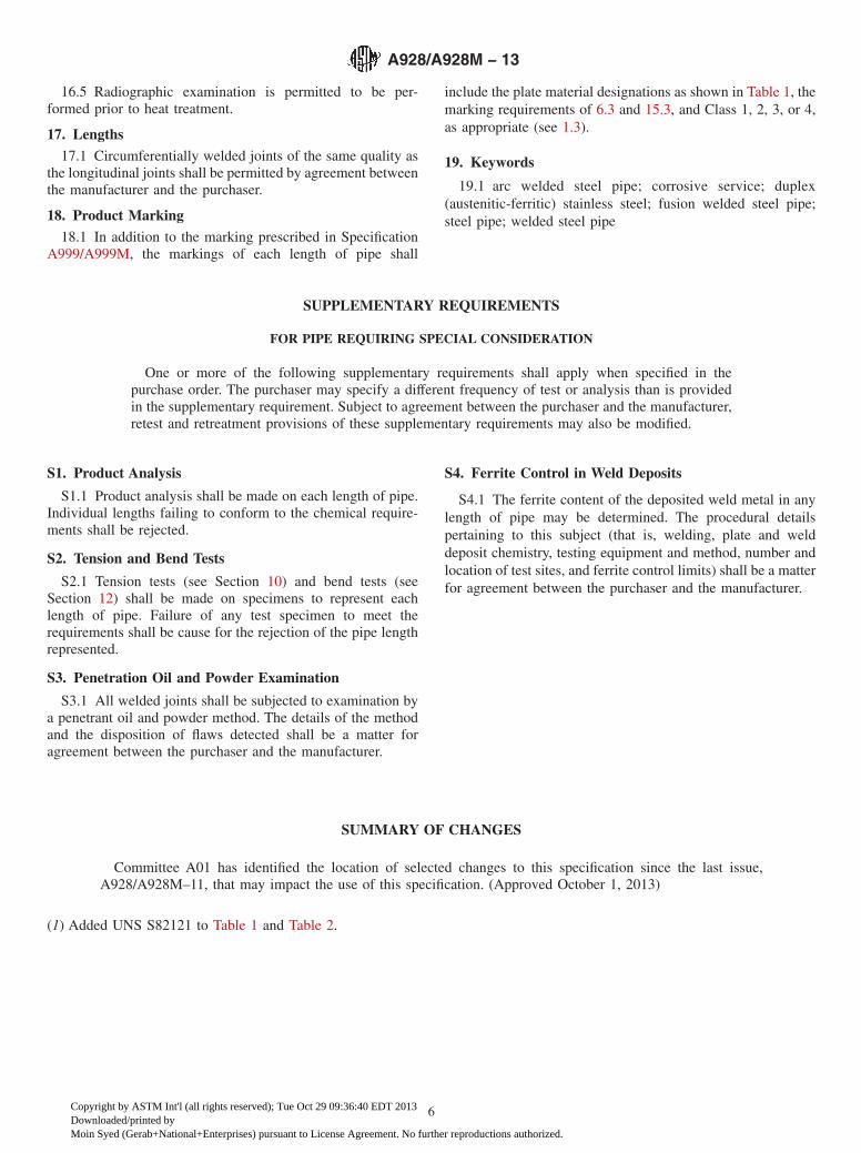
16.5 Radiographic examination is permitted to be per-formed prior to heat treatment.
17. Lengths
17.1 Circumferentially welded joints of the same quality asthe longitudinal joints shall be permitted by agreement betweenthe manufacturer and the purchaser.
18. Product Marking
18.1 In addition to the marking prescribed in SpecificationA999/A999M, the markings of each length of pipe shall
include the plate material designations as shown in Table 1, themarking requirements of 6.3 and 15.3, and Class 1, 2, 3, or 4,as appropriate (see 1.3).
19. Keywords
19.1 arc welded steel pipe; corrosive service; duplex(austenitic-ferritic) stainless steel; fusion welded steel pipe;steel pipe; welded steel pipe
SUPPLEMENTARY REQUIREMENTS
FOR PIPE REQUIRING SPECIAL CONSIDERATION
One or more of the following supplementary requirements shall apply when specified in thepurchase order. The purchaser may specify a different frequency of test or analysis than is providedin the supplementary requirement. Subject to agreement between the purchaser and the manufacturer,retest and retreatment provisions of these supplementary requirements may also be modified.
S1. Product Analysis
S1.1 Product analysis shall be made on each length of pipe.Individual lengths failing to conform to the chemical require-ments shall be rejected.
S2. Tension and Bend Tests
S2.1 Tension tests (see Section 10) and bend tests (seeSection 12) shall be made on specimens to represent eachlength of pipe. Failure of any test specimen to meet therequirements shall be cause for the rejection of the pipe lengthrepresented.
S3. Penetration Oil and Powder Examination
S3.1 All welded joints shall be subjected to examination bya penetrant oil and powder method. The details of the methodand the disposition of flaws detected shall be a matter foragreement between the purchaser and the manufacturer.
S4. Ferrite Control in Weld Deposits
S4.1 The ferrite content of the deposited weld metal in anylength of pipe may be determined. The procedural detailspertaining to this subject (that is, welding, plate and welddeposit chemistry, testing equipment and method, number andlocation of test sites, and ferrite control limits) shall be a matterfor agreement between the purchaser and the manufacturer.
SUMMARY OF CHANGES
Committee A01 has identified the location of selected changes to this specification since the last issue,A928/A928M–11, that may impact the use of this specification. (Approved October 1, 2013)
(1) Added UNS S82121 to Table 1 and Table 2.
A928/A928M − 13
6
Copyright by ASTM Int'l (all rights reserved); Tue Oct 29 09:36:40 EDT 2013Downloaded/printed byMoin Syed (Gerab+National+Enterprises) pursuant to License Agreement. No further reproductions authorized.

ASTM International takes no position respecting the validity of any patent rights asserted in connection with any item mentionedin this standard. Users of this standard are expressly advised that determination of the validity of any such patent rights, and the riskof infringement of such rights, are entirely their own responsibility.
This standard is subject to revision at any time by the responsible technical committee and must be reviewed every five years andif not revised, either reapproved or withdrawn. Your comments are invited either for revision of this standard or for additional standardsand should be addressed to ASTM International Headquarters. Your comments will receive careful consideration at a meeting of theresponsible technical committee, which you may attend. If you feel that your comments have not received a fair hearing you shouldmake your views known to the ASTM Committee on Standards, at the address shown below.
This standard is copyrighted by ASTM International, 100 Barr Harbor Drive, PO Box C700, West Conshohocken, PA 19428-2959,United States. Individual reprints (single or multiple copies) of this standard may be obtained by contacting ASTM at the aboveaddress or at 610-832-9585 (phone), 610-832-9555 (fax), or [email protected] (e-mail); or through the ASTM website(www.astm.org). Permission rights to photocopy the standard may also be secured from the ASTM website (www.astm.org/COPYRIGHT/).
A928/A928M − 13
7
Copyright by ASTM Int'l (all rights reserved); Tue Oct 29 09:36:40 EDT 2013Downloaded/printed byMoin Syed (Gerab+National+Enterprises) pursuant to License Agreement. No further reproductions authorized.