
a162723.pdf
457
AFWAI,-TR- 85-3069 BUCKLING OF LAMINATED COMPOSITE PLATES AND SHELL PANELS Arthur W. Leissa The Ohio State University Research Founation 1314 Kinnear Road Columbus, Ohio 43212 N I June 1985 Final Report for the Period November 1980 - January 1985 Approved for public release; distribution unlimiied. Prepared for E FZ. FLIGHT DYNAMICS LABORATORY Air Force Wright Aeronautical Laboratories Air Force Systems Command Wright-Patterson Air Force Base, Ohio 45433 85 12 20 • 03
Transcript of a162723.pdf

AFWAI,-TR- 85-3069
BUCKLING OF LAMINATED COMPOSITE PLATES AND SHELL PANELS
Arthur W. Leissa
The Ohio State UniversityResearch Founation1314 Kinnear RoadColumbus, Ohio 43212
N
I June 1985
Final Report for the Period November 1980 - January 1985
Approved for public release; distribution unlimiied.
Prepared for EFZ. FLIGHT DYNAMICS LABORATORY
Air Force Wright Aeronautical LaboratoriesAir Force Systems CommandWright-Patterson Air Force Base, Ohio 45433
85 12 20 • 03

NOTICE
k. I When Government drawings, specifications, or other data are used for anypurpose other than in connection with a definitely related Government procure-ment operation, the United States Government thereby incurs no responsibilitynor any obligation whatsoever; and the fact that the government may have form-ulated, furnished, or in any way supplied the said drawings, specifications,or other data, is not to be regarded by implication or otherwise as in anymanner licensing the holder or any other person or corporation, or conveyingany rights or permission to manufacture use, or sell any patented inventionthat may in any way be related thereto.
This report has been reviewed by the Office of Public Affairs (ASD/PA) andis releasable to the National Technical Information Service (NTIS). At NTIS,it will be available to the general public, including foreign nations.
This technical report has been reviewed and is approved for publication.
NARENDRA S. KHOT FREDERICK A. PICCHONI, Lt Col, USAFProject Engineer Chief, Analysis & Optimization Branch"Design & Analysis Methods Group
FOR THE COMMANDER
Ch~k S tructures &Dynamics iv.
"If your address has changed, if you wish to be removed from our mailinglist, or if the addressee is no longer employed by y,)ur organization pleasenotify AFWAL/FIBRA, W-PAFB, OH 45433 to help us maintain a current mailinglist".
Copies of this report should not be returned unless return is required bysecurity considerations, contractual obligations, or notice on a specificdocument.
S. UNCLASSIFIED
SECURITY CLASSIFICATION OF THIS PAGE
Unclassified _______________________2.. SECURITY CLASSIFICATION AUTH'ORITY 3 ITISTO/VILBLT FRPR
Approved for public release; distribution2b. OE CLASSI FICATI ON/OOWNG RAODING SCHEDULE nimtd
4. FillFORMING ORGANIZATION REPORT NUMGER(S) S. MONITORING ORGANIZATION REPORT NUMSERI[S)
762513/713464 AFWAL-TR-85-3069
641 NAME OF PERFORMING OGANIZAYION 86. OPICICE SYMBOL 7&. NAME Of MONITORING ORGANIZATIONThe Ohio St~ste University Ilf applicable)Sponsored Programs Adm. Flight Dynamics Laboratory (AFWAL/FIBRA)
1*~ AOORE6S3 (CIII,. State and 7,P Code) 7b. ADDRESS (City, State and ZIP Code)1314 Kinnear Rcid Wrigh-PattrsonAFB ___4543-655
Columbus, L'h-i' 43212 Wih-atro F H44365
so NAME OF FUNOINO/SPONSORING Bb. OFFICE SYMBOL 9. PROCUREME~NT INSTRUMENT IDENTIFICATION NUMBERORGANIZATION (it 0401nrb?.beJ
F33615-81-K-3203
ac ADDRESS (City, State and ZIP Code) 10. SOURCE OF FUNDING NOS.
PROGRAM PROjECT %rASI( W'ORKC UNITe LEME NT NO. No. NO. NO.
111 TITLE Itintude Securitys Claaeafieation) 611 02F 2307 Ni1 1 5
S2Q. PERSONAL At.THORIS)Arthur W. Leissa
13a. TYPE OF REPORT 13b. TIME COVERED 14. DATE OP REPORT IYt.. Mo., F;7'i ¶5. AGE COUNT
*Final FROM L4DMTOJJ/20O/R51 June 19854516. SUPPLE MI14TARY NOTATION
COSAT CODES I&. SUBJECT TERMS XCOnthnU* OR reUffu if A@ne"ear. and Identify by block nlumber)0ILrD GROUP SUBu. OR. bclnvbainisaiiy lts hls
__ 0 panels, composite materials*9 ABSTRACT (Continue on eveihe if neceu..' and Idmntify by block nurmberi
*BUCKLING OF L-A'-IATED COMPOSITE PLATES AND SHELL PANELS
T his work sijmmari 'zes the technical literature dealing with buckling arf! post-bucklijug behavior of laminated composite plates and shell panels. Emphasis is given
to odrnmaterials used in the aerospace industry having fiber-matrix constituents(e.g., glassr-epoxy, L..rion-epoxy, graphite-epoxy, boron-aluminum), but other applicationsare alsrn co'nside,-ed (e.g., plywood, paperboard). Geometric configurations taken up areeither flat (plates) or cylindrically curved (shells), and have rectangul-ir planform.All Possible typ,...s of loading conditions and edge constraint conditions are considered.Both s\'mmetrically auid unsymnmetrically lai c-. onfigurrtions are included, withs, imet .-al laincintes represented by orthotrcpic or anisotropic plate or shelthoy
_ _ _ _ _ _ _ _(continued)
20. 0IbTARUUfIUN/AVAILA@ILITY OP ABSTRACT 21. ABSTRACT SECURITY CLASSIPICATION
UNCLASSI~fCC/UNLIMITEO ( SAMEI AS RPT. LC OTIC USERS C~ NLASFE
22a. NAME OF RESPOP' OLE INCIVICUAL 22b. TELEPHONE NUMBER 22c. OFFICE SYMBOL
N. S. KHOT tnld m oe
1(513) 255-6992 1 AfWALLIFIBRAO) FORM 14773,83APR ETONPIA7iOSLT.UNCLASSIFIED
SECURITY CLASSIFICATION O0 THIS PAGE

UNCLASSIFIED .
WCURIY CLAUIPICATION OP THIS PAGE
Block 19 (Abstract) - Continued
")Complicating effects dealt with include: internal holes, shear deformation,sandwich plates with soft cores, local instability, inelastic materials, hygrothermaleffects and stiffeners. Approximately 400 references are used. Extension numericalresults are presented in graphical and tabular formj Both theoretical and experi-mental results are summarized. ! a
ii U SIFIEDSiCURITY CLAIIPIFICATION OFT HIS PAOE

FOREWORD
This final technical report was prepared by A. W. Leissa.
Department of Engineering Mechanics, The Ohio State University,
Columbus, Ohio, 43212 for the Flight Dynamics Laboratory, Air Force
Wright Aeronautical Laboratories, Air Force Systems Command, Department
of the Air Force, Wright-Patterson Air Force Base, Ohio 45433 under
Contract No. F33615-81-K-3203, Project 2307, Work Unit 2307N115. The
Air Force Program Monitor was Dr N. S. Khot, AFWAL/FIBRA.
IAL!
- .s P r:0-•ro
#I
S.......
I

TABLE OP CONTENTS
CHAPTER PAGE
I Introduction 1
Ii Orthotropic Plates - All Edges Simply Supported 11
2.1 Uniform Uniaxial Loading 132.2 Uniform Biaxial Loading 222.3 Uniform Shear Loading 302.4 Combined Compression and Shear Loading 402.5 Other Loadings 43
III Orthotropic Plates - Two Opposite Edges Simply Supported 49
3.1 Exact Solution of the Equilibrium Equation 493.2 SCSC 533.3 SCSS 613.4 SCSF 673.5 SSSF 693.6 SFSF 763.7 Elast.c Edge Constraints 79
IV Orthotropic Plates - Other Edge Conditions 83
4.1. CCCC 874.2 CCCS 934.3 CCSS 954.4 Other Edge Conditions 96
V Anisotropic Plates 104
5.1 SSSS 1055.2 SCSC 1405.3 SFSF 1465.4 CCCC 1465.5 Elastic Edge Constraints 156
VI UnsymmetLic Laminates 164
6.1 SSSS 1676.2 SFSF 1946.3 CCCC 194
v

CHAPTER PAGE
VII Complicating Effects 201
7.1 Internal Holes 2017.2 Shear Deformation 2047.3 Sandwich Plates with Soft Cores 2357.4 Local Instability 2387.5 Inelastic Materials 2417.6 Hygothermal Effects 249
VIII Postbuckling and Imperfections 254
8.1 Equations for Postbuckling Analysis 2558.2 Postbuckling Results 2588.3 Imperfection Analysis 287
IX Stiffened Plates 298
X Buckling of Cylindrical Shell Panels 310
10.1 Cylindrical Shell Buckling Equations 31310.2. Numerical Results 315
XI Postbuckling and Imperfections in Shell Panels 344
11.1 Postbuckling Studies 34411.2 Imperfections 353
References 378
Appendix: Plate Buckling Equations 413
A.1 Plate Stiffness Equations 413A.2 Governing Differential Equations 419A.3 Boundary Conditions 429A.4 Energy Functionals 435A.5. References for Appendix 439
vi

LIST OF FIGURE TITLES
Figure 1.1. Representative curves of load versus transverse dia-placement.
Figure 1.2. SCSF plate.
Figure 2.1. SSSS plate with uniform, uniaxial stress.
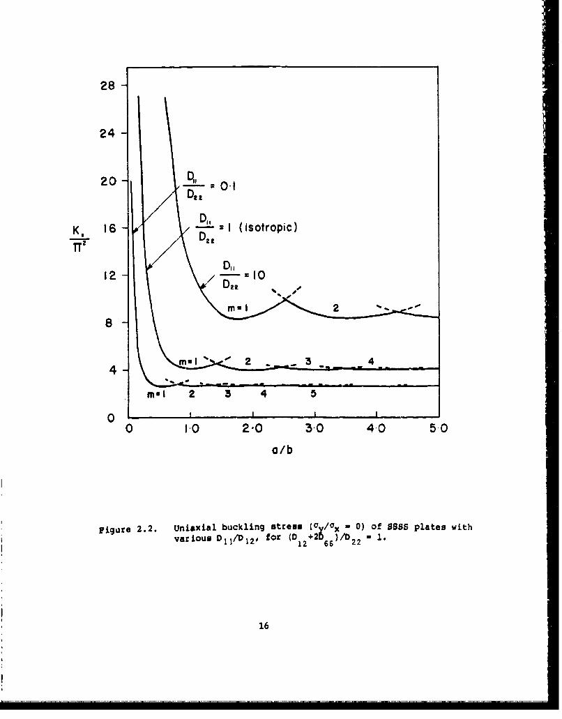
Figure 2.2. Uniaxial buckling stress (Oy/Ox - 0) of SSSS plates withvarious D,,/D,). for (D 2+2D66 )/D 2 2 = 1.
Figure 2.3. SSSS plate with uniform, biaxial stresses.
Figure 2.4. Hydrostatic stress buckling ((Y/ax = 1) of SSSS plateswith various D /D22' for (D2 +2D )/D 1.
1122D1 66 22
Figure 2.5. Tension-compression buckling (cy/ax = -1) of SSSS plateswith various D I/D for (D +2 )/D
N1 22' 12 66 22
Figure 2.6. SSSS plate with uniform shear stress.
Figure 2.7. Buckled mode shape of an infinite, isotropic strip loadedin shear.
Figure 2.8. Shear buckling parameters for SSSS orthotropic plates[32].
Figure 2.9. SSSS plate with linearly varying inplane stresses.
Figure 2.10. Buckling parameter for linearly varying edge load.
Figure 3.1. SCSC plate with uniform, biaxial stresses.
Figure 3.2. Single parameter buckling curves for uniaxial and biaxialloading, as determined by Wittrick [57].
Figure 3.3. Uniaxial buckling parameters for SCSC orthotropic plates.P
Figure 3.4. Buckling parameter ks for CSCS plates loaded in shear.
Figure 3.5. SCSS plate.
Figure 3.6. Uniaxial buckling parameters for SCSS orthotropic plates.
Figure 3.7. SCSF plate.
vii

Figure 3.8. Uniaxial buckling parameters for SCSF orthotropicplates (c - 0.2).
Figure 3.9. Uniaxial buckling parameters for SCSF orthotropicplates (E - 0.3).
Figure 3.10. SSSF plate.
Figure 3.11. Uniaxial buckling parameters for SSSF orthotropicplates (E a 0.2).
Figure 3.12. Uniaxial buckling parameters for SSSF orthotropicplates (6 - 0.3).
Figure 3.13. SFSF plate.
Figure 3.14. The function f, to be used in Equation 3.53 for theuniaxial buckling of SESE orthotropic plates.
Figure 3.15. Continuous SSSS plate with intermediate supports aty = 0.3b and 0.7b; a/b - 0.5.
Figure 4.1. Buckling parameters for uniaxially loaded isotropicplates.
Figure 4.2. Uniaxial buckling parameters for CCCC orthotropicPlatcr.r
Figure 4.3. Shear buckling parameters for CCCC orthotropic plates[65].
Figure 4.4. Buckling parameter ks for CCCC plates loaded in shear.
Figure 5.1. Compressive buckling parameters Nx for graphite-epoxy,angle-ply plates (65].
Figure 5.2. Shear buckling parameters Nxy for graphite-epoxy,angle-ply plates (65].
Figure 5.3. Optimum fiber orientations for SSSS, angle-ply platessubjected to uniaxial loading.
Figure 5.4. Optimum fiber orientations for SSSS, angle-ply platessubjected to shear loading.
Figure 5.5. Buckling parameters for SSSS, angle-ply plates sub-jected to combined axial compression and shear.
viii
Io - . .-

Figure 5.6. Optiuium material axis or ientation versus aspect ratiofor a uniaxially loaded SSSS plate (unidirectional,medium orthotropy laminate).
Figure 5.7. Variation of critical stress with material axis orien-tation, corresponding to a/b - 1 and 2.5 in Figure5.6 (unidirectional, medium orthotropy laminate).
Figure 5.8. Variation of critical stress with material axis orien-tation, a/b = 2.5 (angle-ply, mild orthotropy laminate).
Figure 5.9. Variation of critical stress with material axis orien-tation, a/b = 2.5 (unidirectional, severe orthotropylaminate).
Figure 5.10. Variation of critical stress with material axis orien-tation, a/b = 1 (unidirectional, severe orthotropylaminate).
Figure 5.11. Comparison of anisotropic and orthotropic solutions foruniaxial buckling of a parallel-fiber CCCC plate.
Figure 5.12. Node lines for the buckled anisotropic CCCC platescorresponding to Table 5.18.
Figure 5.13. Optimum filament orientation for the uniaxial bucklingof a CCCC plate.
Figure 5.14. Optimum filament orientation for the uniaxial shear ofa CCCC plate.
Figure 5.15. Buckling parameters for CCCC angle-ply plates subjectedto combined axial compression and shear.
Figure 5.16. Uniaxial compression buckling parameters for rota-tionally constrained, angle-ply plates (a/b = 1).
Figure 5.17. Uniaxial compression buckling parameters for rota-tionally constrained, angle-ply plates (a/b = 2).
Figure 5.18. Uniaxially compression buckling parameters for rota-tionally constrained, angle-ply plates (a/b - 5).
Figure 5.19. Shear buckling parameters for rotat!onally constrained,angle-ply plates (a/b = 1).
Figure 5.20. Shear buckling parameters for totationally constrained,angle-ply plates (a/b = 2).
ix

:igure 5.21 Shear buckling parameters for rotationally constrained,angle-ply plates (a/b = 5).
Figure 6.1. Examples of symmetrical, antisymmetrical and unsym-metrical cross-ply laminates.
Figure 6.2. Comparison of antisymmetrical and orthotropic solutionswith varying a/b for uniaxially loaded, cross-plyplates having 52 edge conditions.
Figure 6.3. Comparison of antisymmetrical and orthotropic solutionswith varying EI/E 2 for uniaxially loaded, cross-plyplates having S2 edge conditions (a/b = 1).
Figure 6.4. Unsymmetrical laminate having one 900 layer locatedsecond from the bottom.
Figure 6.5. Comparison of unsymmetrical, orthotropic and parallel-fiber solutions for graphite/epoxy, cross-ply plateshaving S2 edges and the layups shown in Figure 6.4.
Figure 6.6. Comparison of unsymmetrical, orthotropic and parallel-fiber solutions for boron/epoxy, cross-ply plateshaving S2 edges and the layups shown in Figure 6.4.
Figure 6.7. Comparison of antisymmetrical and orthotropic solutionswith varying lamination angle for uniaxially loaded,angle-ply plates having S3 edge conditions (a/b = 1).
Figure 6.8. Comparions of antisymmetrical and orthotropic solutionswith varying lamination angle for biaxially loaded,angle-ply plates having S3 edge conditions (a/b = 1).
Figure 6.9. Uniaxial buckling loads for antisymmetric, angle-plylaminates having SSSS (S4) edge supports (a/b = I,S- N450).
Figure 6.10. Shear buckling loads for antisymmetric, cross-plylaminates having SSSS (S2) edge Lupports (a/b - 1,G12 /E22 m 0.5,V 1 2 ' 0.25).
Figure 6.11. Shear buckling parameters for antisymmetric, cross-ply,SSSS (S2), graphite-epoxy plates.
Figure 6.12. Shear buckling parameters for antisymmetric, cross-ply,SSSS (S2), boron-epoxy plates.
Figure 6.13. Shear buckling parameters for anytisymmetric, cross-ply, SSSS (S2), glass-epoxy plates.

Figure 6.14. Buckling parameters for biaxially-loaded CCCC (Cl),unsymmetrically laminated, square, angle-ply plates.
Figure 7.1. Uniaxially loaded plate with a central, circular hole.
Figure 7.2 Critical uniaxial buckling stress ratio tor SSSS ortho-tropic plates with holes.
Figure 7.3. Buckling of a uniaxially loaded, SSSS, 1450 angle-ply,square plate having an infinite number of layers, withand without shear deformation.
Figure 7.4. Uniaxial buckling parameters for SSSS orthotropicplates with and without shear deformation (h/a = 0.1).
Figure 7.5. Uniaxial buckling parameters for SSSS orthotropicplates with ane without shear deformation (h/a = 0.04).
Figure 7.6. Comparison of exact elasticity, classical plate theory(CPT) and shear deformation theory (SDT) solutions foruniaxially loaded, SSSS cross-ply laminates.
Figure 7.7. Uniaxial buckling parameters for SCSC orthotropicplates with and without shear deformation (h,/a = 0.1).
Figure 7.8. Uniaxial buckling parameters for SCSC orthotropicplates with and without shear deformation (h/a = 0.04).
Figure 7.9. Uniaxial buckling parameters for SCSS orthotropicplates with and without shear deformation (h/a = 0.1).
Figure 7.10. Uniaxial buckling parameters for SCSS orthotropicplates with and without shear deformation (h/a = 0.04).
Figure 7.11. Uniaxial buckling parameters for SSSF orthotropic
plates with and without shear deformation (h/a = 0.1).
Figure 7.12. Cross-section of web-core construction.
Figure 7.13. Types of buckling failure for soft-core sandwichplates.
Figure 7.14. Typical stress-strain curves ror fiber-reinforced com-posite materials [239].
Figure 7.15. Ratio of nonlinear to linear elastic buckling loadsfor boron-epoxy and graphite-epoxy, SSSS, unidirec-tional laminates.
Xi
hA- -

Figure 7.16. Ratio of nonlinear to linear elastic buckling loads forboron-aluminum, SSSS, unidirectional laminates.
Figure 7.17. Uniaxial buckling loads of unsymmetric, SSSS, cross-ply, boron-aluminum plates.
Figure 7.18. Uniaxial buckling loads of unsymmetric, SSSS, cross-*W ply, boron-epoxy plates.
Figure 7.19. Thermal buckling of a CFCF symmetrically laminated,graphite-epoxy plate.
Figure 7.20. Hygrothermal effects upon the uniaxial buckling stressresultant of an SSSS plate.
Feigure 7.21. Hygrothermal effects upon the uniaxial buckling stressresultant of a CCCC place.
Figure 8.1. Postbuckling uniaxial stress-deflection curves for iso-tropic and orthotropic, SSSS plates (a/b = 1).
Figure 8.2. Load-shortening curves for the plates of Table 8.2(mb/a - 1).
Figure 8.3. Load-shortening curves for the plates of Table 8.2(mb/a - 1.33).
Figure 8.4. Load-shortening curves for the plates of Table 8.2.(mb/a a 2).
Figure 8.5. Load-shortening curves tor the plates of Table 8.2(mb/a = ).
Figure 8.6. Effective widtl.j during postbuckling for the plates ofTable 8.2 (mb/a - I).
Figure 8.7. Postbuckling load-deflection curves for CCCC, uniaxiallyloaded, isotropic and orthotropic plates.
Figure 8.8. Postbuckling deflection-load curves for anisotropic(N450 angle-ply), graphite-epoxy plates (a/b - 1).
Figure 8.9. Postbuckling deflection-load curves for anisotropic(parallel-fiber), graphite-epoxy plates (a/b = 1).
Figire 8.10. Load-shortening curves for SSSS, 2-layer, angle-plyplates.
xii

Figure 8.11. Postbuckling load-deflection curves for SSSS, uni-axially and biaxially loaded, unsymuetricallylaminated, 4-layer, N450 angle-ply plates (a/b = 1).
Figure 8.12. Nondimensional bending moments at the centers of thebuckled plates of Figure 8.11.
Figure 8.13. Displacement-load curves for SSSS, unsymmetricallylaminated, cross-ply plates (a/b - 1).
Figure 8.14. Postbuckling load-deflection curves for CCCC, unsym-metrically laminated, cross-ply plates (a/b = 1).
Figure 8.15. Comparison of postbuckling curves for CCCC, unsymmetri-cally laminated, cross-ply plates of various materials(a/b = 1).
Figure 8.16. Comparison of postbuckling curve. for CCCC and SSSS,4-layer, t450 angle-ply, graphite-epoxy, non-square(a/b = 1.5) plates under uniaxial compression.
Figure 8.17. Deflection-load curves for shear-loaded, N450 angle-ply,SSSS plates having two layers (a/b - 1).
Figure 8.18. Deflection-load curves for shear-loaded, 1450 angle-ply,SSSS, graphite-epoxy plates (a/b = 1).
Figure 8.19. Deflection-load curves for shear-loaded !6, angle-ply,SSSS, graphite-epoxy plates (a/b = 1).
Figure 8.20. Deflection-load curves for shear-loaded N450, four-layer, graphite-epoxy plates.
Figure 8.21. Experimental load-end shortening curves for uniaxiallyloaded CSCF graphite epoxy plates.
Figure 8.22. Load-deflection curves for cross-ply, CFRP plates havingrotational edge constraints (a/b - 1).
Figure 8.23. Load-deflection curves for cross-ply, GFRP plates havingrotational edge constraints (a/b - 1).
Figure 8.24. Load-displacement curves for eccentrically loaded, two-layer, SSSS, angle-ply plates (a/b - 1).
Figure 8.25. Load-displacement curves for eccentrically loaded, two-layer, SSSS, angle-ply plates (a/b - 1).
xiii

Figure 8.26. Load-displacement curves for eccentrically loaded,four-layer, SSSS, angle-ply plates (a/b - 1).
Figure 8.27. Load-displacement curves for eccentrically loa&d,four-layer, SSSS, angle-ply plates (a/b = 2).
Figure 8.28. Southwell plot and load-displacement curves for
Mandell's plate 201 (SSSS).
Figure 9.1. Typical plate stiffening elements.
Figure 9.2. Characteristic buckling modes of J-stiff-ýned plates.
Figure 9.3. Comparison of theoretical buckling loads from variousanalyses for a blade-stiffened plate subjected tocombined longitudinal compression and shear loading.
Figure 9.4. Structural efficiencies of various stiffened plate con-figurations.
Figufe 9.5. Structural efficiencies of graphite-epoxy, blade-
stiffened plates.
Figure 10.1. Circular cylindrical shell panel.
Figure 10.2. Circumferential buckling parameters for shear-diaphragmsupported, cross-ply shell panels.
Figure 10.3. Boundary conditions along straight edges of shell panelsanalyzed by Viewanathan, Tamekuni and Baker.
Figure 10.4. Variation of Nx with curvature parameter for shellpanels of Figure 10.3.
Figure 10.5. Variation of Ny with axial half-wave length (X) forb"/Rh - 300.
Figure 10.6. Variation of Ny with axial wave-length (X) for b 2/Rh - 1.
Figure 10.7. Variation of Ny with curvature parameter.
Figure 10.8. Variation of Nxy with axial half-wave length (X) forb2/Rh - 700.
Figure 10.9. Variation of Nxy with curvature parameter.
Figure 10.10. Combined stress buckling parameters (-Nx Nxy).
XIV

Figure 10.11. Combined stress buckling parameters (-Ny Nxy).
Figure 10.12. Combined stress buckling parameters (Nx a NY)-
Figure 10.13. Combined stress buckling parameters (Nx a NY u -Nxy).
Figure 10.14. Axial buckling loads of CCCC, angle-ply shell panels(a/b - 1, a/R - 0.5, R/h a 2000).
Figure 10.15. Variation of axial buckling load with decreasingcurvature (CCCC, a/b = 1, a/h - 2000, a a 250 mm).
Figure 10.16. Effect of shear loading direction upon the criticalbuckling loads of CCCC shells having unidirectionallayups (a/b - 1, a/R - 0.5, R/h - 2000).
Figure 10.17. Compression-shear interaction curves for CCCC, unidirec-tionally laminated (0 a 450), shell panels with variouscurvatures (a/b - 1).
Figure 10.15. Compression-shear interaction curves for CCCC shellpanels with various layups (a/b - 1, a/R a 0.5,R/h - 2000).
Figure 10.19. Compression-shear interaction curves for CCCC, unidirec-tionally laminated (e a 450), shell panels of variousmaterials (a/b - 1, a/R - 0.5, R/h a 2000).
Figure 10.20. Comparison of uniaxial buckling loads for clamped andsimply supported edge conditions (a/b - 1, a/R - 0.5,Pl/h a 2000).
Figure 10.21. Comparison of uniaxial buckling loads with varyingnumber of layers in angle-ply (!450) layups (a/b - 1,a/R s 0.5, R/h - 2000).
Figure 10.22. Comparison of positive shear buckling loads with aspectratio for various shell panels (a/R a 0.5, R/h - 2000).
Figure 10.23. Compression-shear interaction curves for SCSC shellpanels having symmetric angle-ply (N450) layups (a/b - 1,a/R a 0.5, R/h - 2000).
Figure 11.1. Postbuckling load-deflection curves for SSSS boron-epoxy panels with unidirectional fibers at 8 - 450.
Figure 11.2. Postbuckling load-deflection curves for SS boron-epoxy shell panels with various ply layups.
xv

A I
Figure 11.3. Postbuckling load-defection curves for SSSS shellpanels of various materials with a symmetric four-layer, angle-ply layup.
Figure 11.4. Experimentally determined end-shortening curves for twoof the shell configurations of Table 11.1.
Figure 11.5. Comparison of theoretical and experimental end-shorten-ing curves for the 12x12(90,0) 2s panels of Table 11.1.
Figure 11.6. Load-defleition curves for shell panels having variouslayups and axial loading.
Figure 11.7. Effect of initial imperfections on load-deflectioncurves for an axially loaded, symmetrically laminatedshell panel.
Figure 11.8. Effect of initial imperfections on load-deflectioncurves for an axially loaded, unsymmetrically laminatedshell panel.
Figure 11.9. Load-deflection curve for an unsymmetrically laminatedshell panel having a rectangular cutout.
Figure 11.10. Load-transverse deflection curves for isotropic, SSSSshell panels having imperfections.
Figure 11.11. Imperfection sensitivity versus shallowness parameterfor orthotropic, cross-ply shell panels (a/b - 1).
Figure 11.12. Imperfection sensitivity versus shallowness parameterfor symmetrically laminated, cross-ply, graphite-epoxy Ishell panels.
Figure 11.13. Load-end shortening curves for axially loaded CFCF,16x8, shell panels having geometric imperfections.
Figure 11.14. Theoretical load-transverse displacement curves corre-sponding to Figure 11.13.
Figure 11.15. Load-end shortening curves for axially loaded, 16x8,
shell panels.
Figure 11.16. Theoretical load-transverse displacement curves corre-
sponding to Figure 11.12 (str-ight edges not con-strained circumferentially).
xvi
-

Figure 11.17. Theoretical load-displacement curves corresponding toFigure 11.12 (straight edges constrained circumferen-tially).
Figure 11.18. Measured initial transverse imperfections (in) for CSCSand CFCF shell panels.
Figure 11.19. Theoretical and experimental load - end shorteningresults for axially loaded, 16x12, CSCS shell panels.
Figure 11.20. Theoretical load - transverse displacement curves foraxially loaded, 16x12, CSCS shell panels.
Figure 11.21. Theoretical and experimental load - end shorteningcurves for axially loaded, CFCF shell panels.
Figure 11.22. Theoretical load - transverse displacement curves foraxially loaded, 16x12, CFCF shell panels.
Figure 11.23. Theoretical transverse displacements of the straightedge generator of a CFCF shell panel with imperfections.
Figure 11.24. Theoretical transverse displacements of the centerlinegenerator of a CFCF shell panel with imperfections.
Figure A.l. Positive stress resultants.
Figure A.2. Positive moment resultants.
Figure A.3. Inplane stress resultants (P) applied to free edges.
xv"i

CHAPTER I. INTRODUCTION
Laminated composite plate and shell panels are becoming increasing-
ly used in aerospace and other technical applications. The accurate
knowledge of critical buckling loads, mode shapes and postbuckling
behavior is essential for reliable and lightweight structural design.
The buckling of isotropic, homogeneous plate and shell panels is
in itself a vast, complicated and somewhat disordered subject. Theoreti-
cal solutions to problems began nearly a century ago with the classical
paper of Bryan [1], and have continued at a rapid rate since that time,
yielding at least 2000 publications dealing with plate bickling in the
technical literature. The best available textbooks dealing with the
subject of plate buckling are those by Timoshenko and Gere [2] and by
Volmir [3,4]. Other useful textbooks dealing generally with the con-
cepts of buckling include ones by Ziegler [5], Simitses [6] and Brush
and Almroth (7]. Handbooks summarizing substantial parts of the plate
buckling literature and, particularly, numerical results for critical
buckling loads, include Part I of the series by Gerard and Becker [8],
the specialized monograph by Bulson [9], and the voluminous work of the
Column Research Council of Japan (10]. In addition, a review paper by
Johns [11] sunmnarized references dealing with shear buckling, and one by
the prcsent writer [12] discussed more recent research.
A major factor responsible for the large amount of literature in
plate buckling is the great variety of shapes, edge conditions and
loading conditions which are considered. Thus, for example, one
encounters references dealing with rectangular, circular, elliptical and
parallelogram (skew) plates. The plates may have holes (cutouts) of
various shapes. Simple edge conditions such as clamped, simply sup-
ported or free arise, as well as the more complicated ones of elastic
S. . . ... . . - ,•.. .. • . .. ' - .. .i -• .. ... • . .. .V V . .i - i.. ... 1 .....1- i -

and discontinuous constraint. Point supports, either internal or along
the edges, as well as line supports may be considered. Inplane loadings
may be uniaxial, biaxial, uniform shear, or other, more complicated cases.
The plates may have stiffeners, either along their edges or internally.
Complicating effects such as an elastic foundation, variable thickness,
shear deformation, and inplane heterogeneity may also be treated.
Laminated composite plates are made up of plies (layers), each ply
being composed of straight, parallel fibers (e.g., glass, boron, graphite)
embedded in and bonded together by a matrix material (e.g., epoxy resin).
Each ply may be considered as a homogeneous, orthotropic material having
a value of Young's modulus (E) considerably greater in the longitudinal
direction than in the transverse directions. Adjacent plies will have
longitudinal axes usually not parallel. Cross-ply laminated plates
arise in the special case when the longitudinal axes of adjacent plies
are perpendicular, whereas angle-ply laminates occur when aijacent layers
are alternately oriented at angles of + e and - e with respect to the
edges of the plate.
Equations governing the buckling of laminated composite plates are
available in several textbooks 113-18], as well as in technical papers
(e.g., [19]). A short derivation of these equations, partly for pur-
poses of defining the notation -tsed in this work, is given in the Ap-
pendix. From there it is seen that the complexity of the governing
equations varies greatly, depending upon the stacking sequence of the
plies.
For symmetrical laminates (i.e., when the plies and their orienta-
tions are identical on either side of the midplane of the plate) the
governing equations are the same as those for a homogeneous, anisotropic
plate. Such configurations are also called "balanced laminates" in the
2

literature, although this phrase is also used to indicate a stacking
sequence which eliminates the bending-twisting coupling, as well as the
bending-stretching coupling. At a typical point on the plate one may
always determine a set of coordinate axes aligned with the principal
directions for the material (i.e., directions of maximum and minimum
stiffness, which are orthogonal to each other. With respect to these
axes the material is orthotropic. However, if the buckling problem is
stated and solved in terms of another set of more conveniently oriented
axes (e.g., the edge directions for a rectangular plate), the differen-
tial equation of equilibrium for a buckling mode becomes more com-
plicated, with bending-twisting coupling appearing by means of additional
terng (see termq containing D arid D in Equation A.23 in the Appendix).16 26In this case the plate will be called "anisotropic" in the present work,
in accordance with long tradition. When the principal axes of material
orthotropy are aligned with the orthogonal axes of the problem, the plate
will accordingly be called "orthotropic", and Equation A.24 governs. In
the literature of laminated composite plate buckling one occasionally sees
the term "specially orthotropic" applied to an orthotropic plate, and even
"generally orthotropic" applied to an anisotropic plate. This terminology
will not be used in the present work.
For an unsymmetrically laminated plate, coupling exists between
bending and stretching of the midplane. This phenomenon was demonstrated
in the theoretical paper by Reissner and Stavsky 120] in 1961. The
coupling between bending and stretching is similar to that encountered
in isotropic shell deformation problems, the order of the system of
governing differential equations is similarly increased from four (for
an anisotropic plate) to eight, the number of boundary conditions that
must be specified is increased from two to four for each edge, and the
buckling problems are correspondingly more difficult to solve.
3

Orthotropic plate buckling analysis apparently was first applied a
half-century ago to deal with stiffened isotropic plates (e.g. [21-23]),
and subsequently became extensively used to study plywood plates (cf.
[24-26]). However, the publication rate of research results increased
rapidly beginning two decades ago as fibrous composite panels were being
to be analyzed for aircraft applications. Several literature surveys on
the buckling of composite plates have been written [27-31), and related
design manuals have been written (cf., 132]).
Plate buckling may be discussed in terms of a plot of inplane
loading force (P) versus the transverse displacement (w) measured at a
representative point on the plate. Classical buckling theory yields the
bifurcation behavior depicted by branches I, II and III of the curves
depicted in Figure 1.1. That is, with increasing P, the curve follows
the ordinate (I) upwards, showing no displacement with increased load
until a critical force (Pcr) is reached. At this bifurcation point the
curve theoretically may continue up the ordinate (II), or may follow a
buckling path, which is horizontal (III) for the linear idealization,
but of increasing slope (IV) for a nonlinear (large displacement)
analysis. The latter curve (IV) is also called a 'postbuckling curve",
for it depicts the behavior of the plate after the buckling load (Pcr)is reached. This behavior is very important for, typically, plates are
able to carry loads far in excess of Pcr before they collapse. Finally,it must be noted that no plate is initially perfectly flat, and that if
initial deviation from flatness exists (usually called a "geometric
imperfection" or "imperfection", although other types of imperfections
may also exist), the P-w curve of Figure 1.1 will follow a path similar
to V. As the imperfection magnitude is decreased, curve V becomes
increasingly kinked in the vicinity of Pcr" For this type of analysis,
no clear buckling phenomenon may be defined.
4

P
II
IW
Figure 1.1. Representative curves of load versus transverse dis-placement.
5op

The standard procedure for determining theoretical values of buck-
ling loads is to solve a mathewatical eigenvalue problem; that is, a
problem governed by differential equations and boundary condi!
of which are homogeneous (i.e., the independent variables do
plicitly appear in the equations). In a relatively few cases
be done exactly. In most cases approximate procedures such as the Ritz,
Galerkin series (superposition), finite element or finite difference
methods are used. The latter procedures, if properly used, will
approach the exact solutions as closely as desired as the sufficient
terms (or degrees of freedom) are retained in the solution, although the
roots of very large determinants may be required.
Critical loads obtained by the procedures described above may be
regarded as the proper values of inplane forces requ'.red to keep a plate
in a position of neutral equilibrium in buckled mode shapes having
infinitesimal amplitudes. The linear eigenvalue problem will typically
yield more than a single buckling load for a given plate and loading.
The lowest (i.e., critical) one is usually the only one sought, although
higher ones may be of interest if they approach the lower ones as para-
meters are changed. Other ways of theoretically determining buckling
loads are: (1) from the free vibration problem (finding values of natural
frequencies which approach zero as inplane loadings are increased), and
(2) from static or dynamic transverse loading solutions in the presence
of inplane forces (transverse displacements approaching infinity, no
matter how small the transverse loads).
Before the buckling eigenvalue problem is solved it is uaually
necessary to determine the initial state of inplane stress throughout the
interior of the plate. For most buckling situations which are analyzed,
this is a trivial step (e.g., uniform or 1.nearly varying stress distri-
butions). For others, it may require solving an anisotropic plane
elasticity problem by approximato methods.
6
T;

Chapters 2 through 7 of the present work are devoted to the
linear, bifurcation buckling of laminated composite plates of
rectangular shape, beginning with the most simple analysis of
symmetrically laminated plates (Chapters 2 through 4) - problems
characterized by classical, orthotropic plate theory. The case when
all four edges are simply suppocted (SSSS) has received considerable
attention and is therefore singled out for Chapter 2. The large amount
of interest in this case is, no doubt, mostly due to the fact that
exact, closed form solutions exist for uniform uniaxial and biaxial
loading. Chapter 3 treats the other 5 sets of edge conditions existing
when two opposite edges are simply supported; that is, SCSC, SCSS, SCSF,
SSSF and SFSF, where C, S and F denote clamped, simply supported and
free edges, respectively, and the edges are labeled in clockwise
sequence around the boundary, beginning with the left edge. Thus, an
SCSF plate is depicted in Figure 1.2. For such cases, as well as those
when one or both of the other two edges are elast!-ally supported, exact
solutions for thý ouckling loads and mode shapes still exist for uniform
uniaxial and biaxial loading; however, the eigenvalues (nondimensional
buckling loads) are not given by explicit formulas, and must be
evaluated as the roots of second or fourth order determinants.
The problems of Chapter 4 have no exact solutions. These comprise
the remaining 15 cases of rectangular, orthotropic plates having"simple" boundary conditions (i.e., C, S or F), including the important
CCCC case, as well as all other conceivable support conditions for
orthotropic plates, such as elastic constraints, discontinuous boundary
conditions and point supports. Chapter 5 generalizes the problem to the
equivalent anisotropic plate representation. Although this class of
problems is more general (requiring at least one additional parameter)
than the orthotropic cases of the preceding three chapters, relatively
little has been done with these configurations. This is, no doubt,
partly because virtually no exact solutions exist, and solutions are
relatively long and tedious, obtained by Approxiamte methodA.
7

"IF "I /Z JI a
I I'I_________________________I________________________
Figure 1.2. SCSF plate.

Unsymmetrically laminated plates are studied in Chapter 6. Some
important progress has been made on these relatively complicated buck-
ling problems, involving coupling between bending and midplane stretch-
ing during a buckling deformation. Chapter 7 takes up all other com-
plicating effects encountered in linear, bifurcation buckling theory.
Among the factors considered are: shear deformation, sandwich panels
(e.g., fibrous composite face sheets with honeycomb cores), variable
thickness, nonlinear stress-strain equations, inelastic material behavior
(plastic or creep buckling), local instabilities (e.g., individual plies)
and hygrothermal effects.
Chapter 8 deals with the po3tbuckling behavior of laminated com-
posite plates, as well as the effects of initial imperfections, and a
large number of referen-es are found to relate to these problems. While
the writer was tempted to separate these considerations into two, sep-
arate chapters, both deal with nonlinear analyses of a similar nature,
the only essential difference being whether or not the imperfection
amplitude is zero. Chapter 9 is a perfunctory attempt to deal with
laminated plates having discrete stiffeners attached. Readers desiring
additional detailed information will have to eeek out those references of
interest among th6 numerous ones listed.
Relatively little was found for the buckling of curved, composite
panels. These are typically of cylindrical curvature, and may be
analyzed by shell theory. What has been found is summarized in Chapter
10.
This summary is limited to composite plate and shell panels of
rectangular planform. Although one can find a few references dealing
with circular, elliptic and parallelogram (skew) plates having rectangu-
lar orthotropy, they are deemed of not sufficient interest to justify the

major broadening of the scope of this monograph which would be required.
For similar reasons, problems having curvilinear orthotropy have been
omitted, notably circular plates having polar orthotropy. It is pos-
sible that future design optimization will include the layout of fibers
in curvilinear patterns with varying spacing (i.e., inplane heterogeneity)
[33], and that curvilinear orthotropic plates of this type will require
inclusion in some future summary.
Finally, although primary attention is given to theoretical results,
particularly those available in nondimensional form, in this monograph,
experimental results are also presented. The primary problems with all
experimental results arez the care which went into the fabrication of the
specimens, the successful accomplishment of the desired test (e.g., Were
the clamped edyes actually clamped ? Were the loads uniformly applied ?)
and the definitive specification of all parameters affecting the problem.
The writer has attempted to include considerable experimental results
which appeared to be properl, obtained and presented.
10
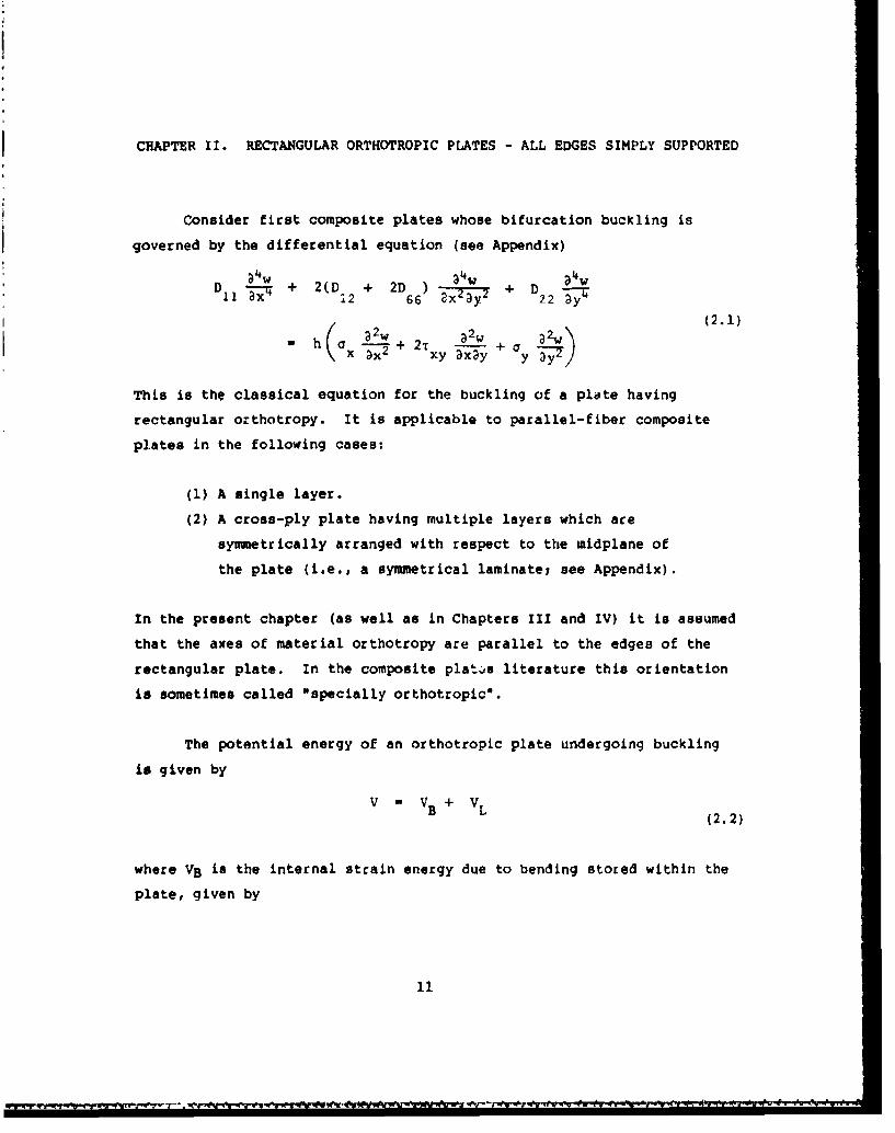
CHAPTER II. RECTANGULAR ORTHOTROPIC PLATES - ALL EDGES SIMPLY SUPPORTED
Consider first composite plates whose bifurcation buckling is
governed by the differential equation (see Appendix)
a•w 34W awDII - + 2(D + 2D) + D1.2 66 2X 22 a
(2.1)h 0x w + 2, ---- y + ay2
This is the classical equation for the buckling of a plate having
rectangular orthotropy. It is applicable to parallel-fiber composite
plates in the following cases:
(1) A single layer.
(2) A cross-ply plate having multiple layers which are
symmetrically arranged with respect to the widplane of
the plate (i.e., a symmetrical laminate; see Appendix).
In the present chapter (as well as in Chapters III and IV) it is assumed
that the axes of material orthotropy are parallel to the edges of the
rectangular plate. In the composite plat.s literature this orientation
is sometimes called *specially orthotropicO.
The potential energy of an orthotropic plate undergoing buckling
is given by
B L (2.2)
where VB is the internal strain energy due to bending stored within the
plate, given by
11
i i i~..'

~~~ 1 I 2Wk 2 2W a2w 3 2Wý2 -t
-E + 32D + D(2w2IB 2 JL 11~" =aD 12 x T =3y 2 7A (2.3)<' • 2w 2
+ 4D 66 t axay dA
and VL is the potential energy of the inplane forces, given by
2ifL L + r _L 2WL h dA (2.4)
A
and the integrals in both expressions are taken over the area of tae
"plate (see Appendix). VL is the negative of the work done by the in-
plane forces during buckling.
For a rectangular plate of dimensions axb, having its edges x a O,a
and y - O,b simply supported, the boundary conditions for the problem
are (see Appendix):
Along x - O'a : a - - 0 (2.5a)
Along y - 0,b W - My- 0 (2.5b)
where Mx and My are the bending moments applied to the edges, which for
an orthotropic plate are given by (see Appendix):( 2w __
M ( a2w + D a2w
( D 12 + D2 2 (.6
y - \12 3aY
Because w - 0 along an edge implies that all derivatives of w taken
tangent to the edge are also zero, Equations 2.5 reduce to:
32wAlong x 0,a W = - 0
(2.7)
32wAlong - ,b w - 0
12

2.1. UNIFORM UNIAXIAL LOADING
Consider first the case of a simply supported plate subjected to
uniaxial loading which yields constant inplane stressesj i. e.,
ex o constant, cy o Txy a 0. This occurs when two opposite edges are
subjected to uniform and equal compressive stresses (see Figure 2.1).
The boundary conditions given by Equations 2.7 aze exactly satis-
fied by assuming the buckling mode shapes
w - c sin 2-- sin n""y (m, n - 1, 2...) (2.8)mn Mn a b
where cnn is an arbitrary (but small) amplitude coefficient. Substi-
tuting Equation 2.8 into 2.1 (or setting VB u-VL, using Equations 2.3
and 2.4) yields the critical buckling stress resultant:
~2D m~22 n 4 /a 21N -.h 2(D 1 + 2D 1\ + m2 2 ,,U (2.9)N x ah 12 -6 •2 b1 +a 22 1;6
This value is clearly a minimum when the buckled mode shape has only one
half-sine wave in the y-direction (i.e., n 1 1). Therefore, the
critical value of stress resultant is
21 D 2y(0) 2 + 2(D 1 + 2DGEf~ D 2 ( )(2) (2.10)
Bquation 2.10 may be put into different forms using various non-
dimensional buckling load parameters. One parameter is consistent with
the one most frequently used in isotropic plate buckling analysis (cf.
(2]). Let
N b 2 a hb 2- x x
K - - - X (2.11)
22 D22
13

y
----,- ---
-- I " -
- xI bl- XI I
Figure 2.1. 8885 plate with uniform, uniaxial stress.
14

Then Equation 2.10 becomes
D k b\ 2m2 + 2D, +a(.1
- D2 2 D2 (
Another nondimensional parameter is more consistent with the Euler
buckling load of one-dimensional beam theory:
* N - a 2 o ha 2K - - - (2.13)
x D2 2 D2.9'
Then Equation 2.10 becomes
K D21 D66 b2 4-1(2.14)
- 22 Vý'22 U2 2 \b +
Other buckling parameters may be defined using, for example, D insteadI'
of D22 in Equations 2.11 and 2.13.
A plot of Equation 2.12 is seen in Figure 2.2 for (D 2+2D66 )/D22 - 1
and for three values of D 1/D 22(10, 1 and 0.1). The value D 11/D 2 2 - 1corresponds to the isotropic case, whereas 10 and 0.1 correspond to repre-
sentative orthotropic plates which are stiffer in the loaded and unloaded
directions, respectively. From the curves it is observed that the
fundamental buckled mode shape may have any number of half waves in the
loaded direction, depending upon the aspect ratio (a/b) and the stiffness
ratio (D 1/D 22) of a particular plate. Thus, for example, for a/b - 2,
the mode shape will have m - 1, 2 and 4 half-waves for D I/D22 - 10, 1 and
0.1, respectively.
More understanding of the curves generated by Equation 2.12 can be
had by rewriting it as
Kx C 2A+ 2C 2 + 2
(2.15)
15
28
24-
20 0i
K. 16- -D11 I (isotropic)
D I2 D I- D11
12- Dzz -10
8
"Mal 2 3 4
0 I I0 I'0 2.0 3"0 4"0 5-0
a/b
rigure 2.2. uniaxial buckling streis (P /Gx 0) of SSSS plates withvarious D1 /D 2 fo 5 66 2iO !/126 for (D 2+2966)/D22
16

where r D D1 2 +2D 6 6
SE mb D C, C2 D (2.16)m 'D22 D22
One obseLves from Equation 2.15 that the shapes of the curves of Figure
2.2 are affected by CI, whereas C2 is only a constant which shifts the
curves vertically but does not change their shapes. Minimizing Equation
2.15 by setting its derivative with respect to r equal to zero, one finds
that the minimum of each curve occurs at
4 __
a . (2.17)
and that the corresponding minimum values are given by
Kx
min-'i - 2 + (2.18)
Thus, for example, for C1 - 0.1 and C2 - 1, minimum values of
Kx/ir2 - 2.632 occur at a/b - 0.562, 1.125, 1.687, ... , as shown by the
bottom curve of Figure 2.2. One physical interpretation of Equation 2.17
is that, for a given value of the stiffness ratio (C1 ), there exists a
unique plate aspect ratio (a/b) for which the plate buckles with a minimum
uniaxial stress into a mode shape which is the product of single half-sine
waves in each direction. Tht same minimum stress then exists for aspect
ratios which are integer multiples (m) of the aforementioned a/b, having
corresponding m half-sine waves in the x-direction. The resulting node
lines x - constant which exist for m > 1 duplicate the boundary conditions
at the edge of a simply supported platel hence, each area of positive and
negative displacement in the mode shape deforms as if it were a single
plato having the aforementioned a/b ratio.
The intersections of buckling parameter curves as seen in Figure 2.2
identify aspect ratios for which a plate can buckle equally easy in either
17
' ~~ ~ ~ T I. W I I 'rI7..4-|... ..

of two mode shapes with the same uniaxial compressive stress. Indeed,
the resulting buckled mode shape may then have any linear superposition
of the two simple mode shapes, with no symmetry (or antisymmetry) of the
mode being required in the x-direction. The curve intersection points may
be determined by equating the right-hand-side of Equation 2.12 with
another right-hand-side obtained by replacing m by m + 1. Solving the
resulting equation for a/b yields
( a) M(m + 1Y)\ C (2.19)
with a critical buckling parameter value of
K ?E M+ ! ti) ý+C 22-- - l M-• + + 2C2 (2.20)
Thus, for example, for C, a 0.1 and C. a 1, intersections of the bottom
curves shown in Figure 2.2 are found at a/b a 0.795, 1.377, 1.948,
with corresponding values of Kx/n 2 - 2.790, 2.685, 2.659, ... , which
approach the minimum value of Kx/ff2 - 2.632 as m and m + 1 increase.
The useful formulas presented above may also be found in the
classic work of Lekhnitskil [171(see pp. 445-452). There, numerical
results for C 2 1.307, and C I 12.1 or 1/12.1 s 0.0826, corresponding2 1
to a 3-layer birch plywood plate bonded by bakelite glue, loaded on
either two sides, were presented. Because of their similarity to Figure
2.2, they will not be repeated here.
In Equation 2.15 it was seen that the buckling load parameter Kx
was expressed as a function of the aspect ratio r and the two stiffness
ratios C1 and C2 . While these ratios are physically meaningful, it is
interesting to note that, mathematically, it is possible to choose
another form of load parameter which is a function of only two pare-
18
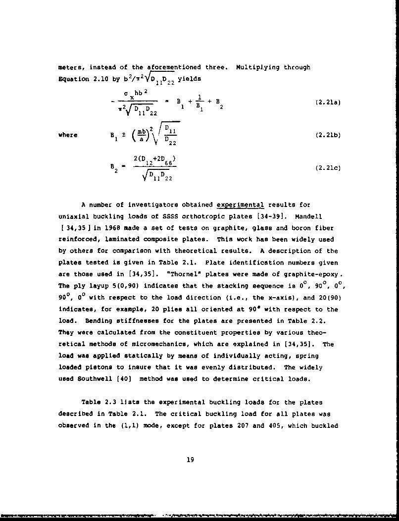
meters, instead of the aforementioned three. Multiplying through
Equation 2.10 by b 2/W 2 DD J)D2 2 yields
a hb 2
SB + +1 + 1 + B
(2.21a)r2;7 1 B 2
1 D7l221
/MbD)2/ I
where B1 a - 57- (2.21b)22
2(D 12+2D 66)B2 F 1 ;2 6 (2.21c)
A number of investigators obtained experimental results for
uniaxial buckling loads of SSSS orthotropic plates [34-391. Mandell
[34,35 ) in 1968 made a set of tests on graphite, glass and boron fiber
reinforced, laminated composite plates. This work has been widely used
by others for comparison with theoretical results. A description of the
plates tested is given in Table 2.1. Plate identification numbers given
are those used in [34,35]. "Thornell plates were made of graphite-epoxy.
The ply layup 5(0,90) indicates that the stacking sequence is 00, 90°, 0°,
900, 00 with respect to the load direction (i.e., the x-axis), and 20(90)
indicates, for example, 20 plies all oriented at 90* with respect to the
load. Bending stiffnesses for the plates are presented in Table 2.2.
They were calculated from the constituent properties by various theo-
retical methods of micromechanics, which are explained in [34,35]. The
load was applied statically by means of individually acting, spring
loaded pistons to insure that it was evenly distributed. The widely
used Southwell [40] method was used to determine critical loads.
Table 2.3 lists the experimental buckling loads for the plates
described in Table 2.1. The critical buckling load for all plates was
observed in the (1,1) mode, except for plates 207 and 405, which buckled
19
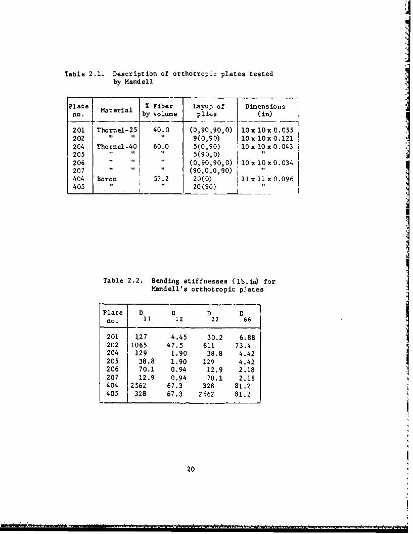
Table 2.1. Description of orthotropic plates testedby Mandell
Plate Mtil % Fiber Layup of Dimensionsno. by volume plies (in)
201 Thornel-25 40.0 (0,90,90,0) 1Ox 10x 0.055
202 " " " 9(0,90) lOx lOx0.121204 Thornel-40 60.0 5(0,90) i0xl0x0.043205 " it 5(90,0) "206 " " " (0,90,90,0) lOx lOxO.034207 " " " (90,0,0,90) "404 Boron 57.2 20(0) i1 x 11 x 0.096405 " " 20(90)
Table 2.2. Bending stiffnesses (lb.ii forMandell's orthotropic pl.ates
Plate D D D Dno. 11 12 22 66
201 127 4.45 30.2 6.88202 1065 47.5 611 73.4204 129 1.90 38.8 4.42205 38.8 1.90 129 4.42206 70.1 0.94 12.9 2.18207 12.9 0.94 70.1 2.18404 2562 67.3 328 81.2405 328 67.3 2562 81.2
20

Table 2.3. Buckling loads (-N, lb/in)for Mandell's SSSSXorthotropicplates
Plate Experimental Theoreticalno.
201 21.7 19.1202 189 204204 15.5 18.7205 16.3 18.7206 6.69 8.72207 5.65 7.44404 271 292
"285*"299**
405 251 223"210*
'$ I 226**
* obtained by Galerkin method** obtained by Ritz method
21
'a,.
. . .. . .

first in the (1,2) mode. Also listed are theoretical values obtained by
utilizing Equation 2.9 and by two approximate methods using the stiff-
ness data given in Table 2.2. and the Galerkin and Ritz methods, as
applied by Chamis [41] and Ashton 142], respectively. The Galerkin and
Ritz methods should both give critical loads equal to or greater than
the values obtained from Equation 2.9, depending upon the trial
functions chosen to represent the buckled mode displacement.
It is interestirig to note that the theoretical values for the
uniaxial buckling loads for cross-ply, symmetrically laminated, square
plates are the same regardless of whether the load is applied to one set
of parallel edges or to the other set, and irrespective of the ply
thickness or stacking sequence, provided that the plate buckles in the
mode having m - n - 1. This statement even includes the special case
when all plies have parallel fiber directions. This fact is seen by
observing Equation 2.21 in Section 2.2, where clearly the same result is
obtained whether Cx a 0 or oy - 0, and is demonstrated in Table 2.3 by
plates 204 and 205. The latter plates are identical 5(0,90) plates
loaded in the two different directions. However, the experimental loads
for the two loading cases are seen to be approximately 5 per cent
different.
Buckling of uniaxially loaded SSSS orthotropic plates is discussed
by many other writers 143-56], typically as part of a more complete in-
vestigation involving other loadings or boundary conditions.
2.2. UNIFORM BIAXIAL LOADING
In this case the problem of Section 2.1 is generalized to include
both components of normal stress - that is, both constant, but not
necessarily equal - but no inplane shear stress. A representative
22
-- - ---- --

+
,II
---IL aI- ___
pFigure 2.3. SSSS plate with uniform, biaxial stresses.
23
-.'-
-• Pi gu_______ .-- - - . S.Spl t w t u io-,.a x a s r ss s

loading is shown in Figure 2.3, where on- of the normal strefsses; (ox) is
compressive, and the other (ay) is tensiLe. For buckling to occur, at
least one of the stresses must be compre3sive.
Taking once again the assumed displacement function given by
Equation 2.8 and substituting it into Equation 2.1, retaining both Ox
and Cyr one obtains the following generalization of Equation 2.9:
h ) 2+ (a)2 "a 2a" 11 .
h(-!+ ah( = - D2 D1 ()+ 2KD1 2 + 2D mx .a y
(fl\141 (2.22)
+. D2 (11)4
Solving Equation 2.22 for the critical stress resultant in terms of the
biaxial stress ratio cy/ax, there results:
2 4
a h a 12 66 ' ) 2 2 b m/x (~/i)2(fn2 (2.23)
-. I +
Unlike the previous case of uniaxial stress (Section 2.1), the critical
buckling load need not necessarily occur for n = i (or m = 1), so both
integers must be retained in general form. In terms of the parameter
defined by Equation 2.11 the nondimensional buckling stress becomes
D D+ (a1 /a n
where a negative value of ay/Ux is used to denote a tensile strevs
2
24

acting in the y-direction, simultaneously with the compressive stress in
the x-direction.
In addition to the case of uniaxial compression (ay/Ox - 0)
already discussed, at least two other important special cases exist.
The first of these is hydrostatic compression, where the biaxial normal
stresses in x, y and all directions are equal (ay/ax = 1). A plot of
Kx/W 2 versus a/b for this case is shown in Figure 2.4 for the same
ratios of elastic moduli used previously in Figure 2.2. As expected, a
plate subjected to hydrostatic compressive stress buckles under less
stress than one carrying only uniaxial stress. Unlike the case of
uniaxial loading, the smallest value of Kx/r 2 always occurs for m - n - 1,
and Kx/n 2 decreases monotonically with increasing a/b. Comparing Figure
2.4 with Figure 2.2, one can see that for an isotropic plate, the
minimum value of Kx/ff2 is 1, compared with 4 for the case of the uni-
axially loaded plate.
Another special case of uniform biaxial stress loading is worthy
of special attention. Here ay/ax - -1; that is, the normal stress in
the y- direction is tensile, and equals the normal compressive stress in
the x-direction in magnitude. In this case all planes making a 45
degree angle with both the x and y axes are in pure shear. A plot of
Kx/w 2 versus a/b for this case is shown in Figure 2.5 for the same
ratios of elastic moduli used previously in Figures 2.2 and 2.4. As
expected, the presence of uniform tensile stress serves to stiffen a
plate. Comparing Figure 2.5 with Figure 2.2, it is seen that for an
isotropic plate, the minimum value of Kx/r 2 is 8, compared with 4 for
the case of the uniaxially loaded plate. Furthermore, while the minimum
buckling load occurs with n - 1 for both loading cases, comparing Figure
2.5 with 2.2, it is observed that tension-compression buckling mode
shapes tend to have more half-waves in the x-direction than the uniaxial
buckling modes.
25

S~14-
12Dz
10 - /• D"I = (isotropic)D,
D228 -/ D,,
112 D 2
6
m 4
m-I
0 I I I
0 ['0 2.0 3.0 4"0 5"0
p/b
Figure 2.4. Hydrostatic stress buckling (0y/Cx l 1) of BSSS plates
with various Dfo/D r o (D. 2 2D )/D22 " 1.
26

56-
48-
Mal• 2 4 6 7
40 D 0Dal
32 D
K1 2 a I (isotropic)TT D22
2 4 - D I I 2 -241
16-L
D2
'I b -f
,• -•% =o/_
8 - m-I 3 4 5 6 7 8
mal0 1 I
0 1.0 2.0 3-0 4"0 5"0
a/b
Figure 2.5. Tension-compresuion buckling (o /ax = -I) of SSSS plateswith various D 11/D 22, for (D +1 D +I D66 - 1.
27

From Equation 2.22 it is seen that for ax negative and a
positive, the smallest value of Kx always occurs when n - 1.
Lekhnitskii [17] showed that in this case, for any given value of oy,
the lowest value of buckling load is given by
K a b2x •2•221(2.25)min-4 x 2 VC + + C(
where ay, as before, is a positive number when the plate is in tension,
and that this minimum occurs wherea m
bb 1b2 (2.26)
He showed further that the intersections of buckling parameter curves
occur at
(2.27)
The validity of Equations 2.25, 2.26 and 2.27 is verified by Figure 2.5
for the case when ay/ax . -1.
In Equation 2.24 it is seen that the buckling load parameter Kx is
a function of the biaxial stress ratio (Oy/Ox), three stiffness ratios
(D1 1/D 22 , D1 2 /D2 2, D6 6/D 22 ), the plate aspect ratio (a/b), and the half-
wave numbers m and n. Thus a careful numerical study of Equation 2.24
would require plotting large numbers of curves for, say, Kx versus a/b
(or mb/a), for various values of the aforementioned ratios.
Wittrick [57] showed that for small values of Oy/Oxi apecifically,
for
- < (2.28)ax Kx
28

Equation 2.24 may be written as
k (+ 2.29)
where m is the number of half sine waves in the x-direction, as before,
and k and X are defined as:
[ cx~hb 2 6)]
+ 2(D + 2D66
o D Dw2 D h 1/2 (2.30)
[D D(l
SD22 a ohb 2 \A- - I -(i+ D22) (2.31)
where, as Wittrick [57] proved, the minimum value of Kx occurs for n - 1
when inequality (2.28) in satisfied. Equation 2.29 is seen to have the
same form as the well-known formula for the uniaxial buckling of an
isotropic plate (cf., Timoshenko and Gere [2], page 352), except that in
the latter case, k and X are simply Kx/n 2 and a/b, respectively, and
the critical buckling loads are determined from a single curve. Thus,
Equations 2.29-2.31 permit the representation of all 8888 orthotropic
plate biaxial buckling loads as a single curve, rather than requiring
many families of curves. This single curve is the middle curve of
Figure 2.2 (i.e., isotropic), with Kx/7r 2 and a/b replaced by k and X of
Equations 2.29-2.31, respectively. Results corresponding to Equations
2.29-2.31 were subsequently derived by Brunelle and Oyibo [58,59] for
this problem in the special case when uy - 0 (i.e., uniaxial loading).
29

Several additional references may be found which deal with the
buckling of biaxially loaded 88S8 orthotropic plates [32,44,45,46,60].
2.3. UNIPORM SHEAR WADING
A rectangular plate having dimensions axb, subjected to uniform
shear stresses throughout, is depicted In Figure 2.6. The buckling of
orthotropic plates due to shear loading received considerable attention
by Bergmann A Reissner (211, Bchmieden [22,61] and Seydel [62-65] a half
century ago. Brief histories of these early contributions may be found
in the works of Lekhr.itskii [171 and Stavsky and Hoff [661.
The case of the infinite orthotropic plate (i.e., a/b - ) loaded
in pure shear has an exact solution for its critical buckling stresses
and mode shapes. This was determined by Bergmann & Reissner [21]
following the same procedure used previously by Southwell and Skan [67]
for isotropic plates. This solution is applicable for long plates (say
a/b >4), regardless of the edge conditions at x - 0,a.
Taking Equation 2.1 with ox a ay * 0, an exact solution may be
found in the form
v(x,y) - f(y)e b (2.32)
where i af-1, b is the plate width and K is a wave-length constant to
be determined. Substituting Equation 2.32 into Equation 2.1 yields the
ordinary differential equation
D f - 2(D +2D) (-nf + iy ( f + D f - 0 (2.33)22 12 66 ) bi b
30

y
-------- du - - -a - - -Alm
1lw L.......p...- l- now "or- "-
7xy
F igure 2.6. 8958 plate with uniform shear stress.
31.

where the primes denote differentiation with respect to x. The solution
of Equation 2.33 takes the form
f(y) - A1 e + A2 e + A3 e + A e (2.34)
where a " 4 are the roots of a fourth degree polynomial equation
arising from Equation 2.33. Substituting Equations 2.32 and 2.34 into
the four simply-supported boundary conditions which exist at y a O,b
Equations 2.7, one obtains a fourth order characteristic determinant
containing both K and TXy. For each value of K there exists at least
one value of T.y. The critical value of TXy is the lowest one which can
be found. It can be shown that the solution range is determined by the
parameter C2, where C and C2 are as given by Equations 2.16. For
1 CI/C2 :.-, the critical values of Txy and K are determined from
Tx hb2 - (2.35a)D 1y k
22
K - k2 bVCI (2.35b)
where k 1 and k 2 are given in Table 2.4. For 0 SV ciC 2 1, the values
are determined from
S(2.36a)
K k4b 2 (2.36
where k3 and k4 are given in Table 2.5.
For an isotropic material (C 1 a C*2 1), the results obtained from
Equations 2.35 and 2.36 agree with those of Southwell and Skan (67],
viz.
32

Table 2.4. Coefficients k and k2 for the huckling pArmetersof a SS-SS infinite strip loaded in shear.
l k kC 2 12
1 52.68 2.492 43.2 2.283 39.8 2.165 37.0 2.13
10 35. 2.0820 34. -30 - 2.0540 33.0 -
32.50
Table 2.5. Coefficients k3 and k4 for the buckling parametersof a SS-SS Infinite strip loaded in shear.
4E-C I . - -- .C k 3 k 4
0 46.84 -0.05 - 1.92
0.2 47.2 1.940.5 48.8 2.071 52.68 2.49
33

K 52.68, Ki 2.49b (2.37)5lThe buckled mode shape for the isotropic case is shown in Figure 2.7.
It is observed that the half-wave length of the mode in the x-direction
is K/2 - 1.24b, which slightly exceeds the plate width. For comparison,
the infinite strip subjected to uniform uniaxial stress in the x-
direction buckles when-oxhb2 /D22 472 - 39.48 with a half-wave lengthof b (see Section 2.1).
For an orthotropic plate having C a 10, C 2 1 (e.g., a single
layer with fibers parallel to the infinite length), Equations 2.35 and
Table 2.4 combine to yield
K - 39.6 x 1.78 - 70.4s (2.38)
K - 2.16b x 1.78 - 3.85b
whereas if C1 a 0.1, C2 = 1 (e.g., fibers perpendicular to the infinite
length), Equations 2.36 and Table 2.5 yield
K - 47.8 x 1 = 47.88 (2.39)
K- 1.95b x 1 1 l.95b
Thus, infinite strips having fibers parallel to the two simply supported
edges buckle with larger critical shear stress and longer wave length
than strips having the fibers perpendicular to the edges.
The case of the SSSS plate of finite dimensions subjected to
uniform shear stress has no exact solution for the buckling problem,
although one may obf in solutions to any degree of accuracy needed by
various approximate methods.
Perhaps the most commonly used method of solving the problem is to
assume a displacement function (w) to represent the buckling mode, pre-
34

-o -
g-g NOI.03S
S".4J
0~
I44
44
AC U
.- V N01133S350
<: % -
Co'
355

ii
ferably one which satisfies all the boundary conditions, and equate the
work done by the external forces during buckling (-VL), Equation 2.4, to
the bending strain energy, Equation 2.3. This allows one to solve
directly for the critical value of ixy, which will be an upper bound to
the exact value.
More accurate upper bound results may be obtained by choosing dis-
placement functions with additional degrees of freedom, represented by
arbitrary amplitude coefficients, and minimizing the total potential
energy of the system with respect to the coefficients. For example, one
function w which satisfies the SSSS boundary conditions exactly, is
M N
w . sin m-rx sinry (2.40)mn a b
m-l n-l
which is seen to be a generalization of the simpie function representing
the buckling of a uniformly or biaxially loaded plate, Equation 2.8.
Substituting Equation 3.23 into Equations 2.3 and 2.4, the minimizing
equations for the total potential, Equation 2.2, take the form
DV 0 (m - 1,2,...,M; n - 1,2,...N) (2.41)BC mn
This procedure yields a set of H x N homogeneous, linear, simultaneous
equations in the unknown cmn. The solution is the standard eigenvalue
problem obtained by setting determinant of the coefficient matrix equal
to zero. The resulting M x N eigenvalues are upper bound approximations
to the possible buckling loads, and the smallest one is the critical
one. The corresponding buckled mode shapes are found by returning to
the homogeneous set of equations and solving for the amplitude ra.io:cmn/C11 in the standard manner.
36
* -~-* .

An extensive set of results was obtained by Housner and Stein [68,
69], using another approximate method. f.inite difference approach
was followed; however, trigonometric rathe than the con-entional poly-
nomial central finite differences were used, which take advantage of the
sinusoidal form of the buckle pattern to achieve converged solutions
with fewer degrees of freedom, hence reducing computer time. As in the
case of uniaxial loading, it is possible to express a shear buckling
parameter completely in terms of two independent, nondimensional para-
meters involving the aspect ratio and the orthotropic bending stiff-
nesses (see Equation 2.21). The parameters utilized in 168,69] were 0
ani B, defined by
JD1 D 22 b Dl1e ..-D2D ,B (2.42a)D 1 +2D 66 a 22
Values of the nondimensionalshear buckling parameter ks are listed in
Table 2.6, where k. is defined by
r hb 2
k (2,42b)S Tr2VrFD223
should be noted that 0 1 implies an isotropic plate.
A more detailed set of results for the same problem was presented
by Fogg (32], taken from (70]. These are seen in the curves of Figure
2.8. There the same parameters are plotted (ks versus B and e), except
that the scalp for 0 is given in terms of k - 1/0. Changes in mode shape
for the critical load with changing B are indicated by the cusps which
appear on the curves. There would be additional cusps (an infinite
number) for small values of B, but they become difficult to identify.
Each curve of Figure 2.8 arises from two curves of the theoretical
37

Table 2.6. Shear buckling parameters ka for SSSSorthotropic plater (see Equations 2.40for definitions).
6 B 8s B k
0.2 1.0 26.28 1.25 1.0 8.430.8 21.43 0.8 7.08 "I.0.6 17.33 0.6 6.380.5 15.36 0.4 5.750.4 13.77 0.2 5.090.2 11.55 0.1 5.050 10.87 0 4.96
0.4 1.0 15.78 1.667 1.G 7.540.8 12.98 0.8 6.370.6 10.86 0.6 5.850.5 9.93 0.4 5.260.4 9.29 0.2 4.720.2 8.21 0.1 4.68
__ _ _ _ _ _ _ _ _ _ _0 4.600 7.72 0 46
0.6 1.0 12.21 2.5 1.0 6.650.8 10.11 0.8 5.660.6 8.67 0.6 5.320.5 8.09 0.4 4.770.4 7.73 0.2 4.320.2 6.71 0.1 4.330 6.53 0 4.17
0.8 1.0 10.40 5.0 1.0 5.740.8 8.66 O.8 4.940.6 7.57 0.6 4.780.5 7.10 0.4 4.270.4 6.80 0.2 3.900.2 6.02 0.1 3.860 5.79 0 3.75
1.0 1.0 9.31 * 1.0 4.830.8 7.60 0.8 4.220.6 6.91 0.6 4.250.4 6.22 0.4 3.760.2 5.49 0.2 3.470 5.33 0 3.30
38

17 k, (3.32 2.L17;t0,6~) -62 (1-S4 -2J.61-& 0.100 (to I/A .
E Na~c IttR ol02114 1 - VA 2.51612 2 _ _
1 b (02*20i/ I I a I 1 / .
1(0: 11)'4"Y 0 (022)114 - )?/- -
1:3
//I/ý /A'.4
1.2
0.0
0.4
o 0.1 0.2 0.2 0.4 019 0.6 0.7 083 0.9 1-
Figure 2.8. Shear buckling parameters for SSSS orthotropic plates
39

solution. These two curves cross and re-cross each other infinitely
many times as one begins with B - 1 (where the two curves would have
the same value) and moves towards B a 0. Each curve of Figure 2.8 is
therefore the envelope (i.e., lowest values) of two curves
Buckling of orthotropic plates due to shear loading has received
attention from a number of others in the technical literature, [45,46,
58,59,71-76].
2.4. COMBINED COMPRESSION AND SHEAR LOADING
Chamis [43,441 used the Galerkin method with displacements assumed
in the form of Equation 2.40 to analyze the buckling of SSSS orthotropic
plates subjected to combinations of compression and shear loading. Theplates were assumed to be made up of plies having the material proper-
ties given in Table 2.7, resulting in the bending stiffnesses listed in
Table 2.8. Fibe:s were Aither parallel to the x (0 - 0) or y (0 - 900)
directions. Data for aluminum plates of the same thickness are given
for comparison. Numerical results were obtained by setting M = N a 5 in
Equation 2.32, yielding determinants of order 25 from which the approxi-
mate buckling eigenvalues were found.
Table 2.9 presents critical values of buckling loads for the
plates described by Tables 2.7 and 2.8. Three sizes of rectangular
plates were used, being 10.0 inches in one dimension, and either 5.0,
10.0 or 20.0 inches in the other dimensions. Various combinations of
compressive and shear loadings are listed for each plate. Difficulties
with the computer program logic required having a small value of the
compressive stress resultant Nx present when a pure shear (Nxy) loading
was desired. It is observed in Table 2.9 that the composite plates have
buckling loads which are comparable to those of the aluminum plates;
V.':'" 40

Table 2.7. Material properties for plates analyzedby Chamls
Modulus, lb/in2xlO 6Material Ell E2 2 G1 2 v12
Fiber-matrix 32.9 1.8 0.88 0.24Aluminum 10.0 10.0 3.83 0.30
Table 2.8. Bending stiffnesses (lb.in) for Chamis'ortho-tropic plates
Fiberangle D D D D D De(deg) 11 12 16 22 26 66
0 2438 32.3 0 134.8 0 64.890 134.8 32.3 0 2438 0 64.8
Alum. 1 810.1 243.1 0 810.1 0 283.5
41

Table 2.9. Buckling loads Ncr(lb/in) for Chamis' SSSS orthotropicplates
Plate Loading condition 1 Buckling load, Ncrdimensions
(in) ___=0 6 =9 ° Al m
cr cr ccr
5. Oxl0.0 -1 0 0 998 145 500" 0 -1 0 581 581 1279
"-1 -1 0 465 116 400"-1 0 1 948 114 479"0 -1 1 619 395 998"I- -1 1 446 113 389"-0.001 0 1 2185 700 2104
i0.OxlO.0 -1 0 0 286 145 320" 0 -1 0 145 286 320" -1 -1 0 116 116 160" -1 0 1 246 136 277" 0 -1 1 136 246 277" -i -1 1 111 136 153
"-0.001 0 1 531 531 752" -1 -0.75 0 145 122 183
"-1 -0.50 0 191 129 213"-1 -0.25 0 229 137 256
"-1 0.25 0 381 155 426"-1 0.50 0 572 166 571"-1 1.00 0 1330 194 666"-1 -0.50 0.25 190 129 212
" -1 0.50 0.25 549 165 562"t -1 -0.50 0.50 187 127 209" -1 0.50 0.50 496 163 539
20.OxlO.0 -I 0 0 145 145 320"0 -1 0 36 249 125"-1 -1 0 29 116 100
"-1 0 1 99 155 250" 0 -1 1 35 237 120
" -1 -1 1 28 ill 97" -0.001 0 1 175 491 528
42

furthermore, the densities of the composite material and aluminum were
0.06 and 0.09 lb/in , respectively (431.
Sandorff (771 discussed a procedure for modelling stiffened iso-
tropic plates subjected to combined compression and shear by equivalent
orthotropic plate theory, and applied it to the case when all edges are
simply supported.
2.5. OTHER LOADINGS
For the buckling of isotropic plates one finds considerable
results for loading cases where x, Pay and Txy are not everywhere
constant (cf. [2,8,9,10]). This is particularly true for plate models
of web' of beams or girdei; carLyIng bending moment and transverse
6hear. Buckling solutions also exist for isotropic plates subjected to
In-plane point loads or partial edge loads. However, relatively little
h .3 been done for orthotropic plates carrying these more complicated
loadings.
One important case of linearly varying inplane stresses may be
considered as a superposition of constant inplane stresses and linearly
varying stresses which arise from an inplane bending moment. Let the
inplane bending stress variation be expressed as (see Figure 2.9)t
a - -a (1-a a ) (2.43)x 0 b
when a - 0, the stress is uniformly compressive (-ao). When a - 1, the
compressive stress varies from a maximum at one edge to zero at the
other. When a - 2, the tensile stress (+Co) at y - b is the same in
magnitude as the compressive stress (-oo) at y - 0, which is the case of
pure inplane bending. For a > 2, the resultant inplane force is tensile
even though one part of the plate is in compression.
43

Y
-_ x
?iguro 2.9. 8558 plate with linearly varying inpiane stresses.
44

Lekhnitskii [171 solved the problem in two ways. rirst, he
assumed the simple, one-term sinusoidal function given by Equation 2.8
with n - 1, and equated the negative of the work done by the inplane
forces, Equation 2.4, to the strain energy in the plate, Equation 2.3
and arrived at the following approximate expression for the compressive
stress Cog
hb (l-0.) 1-a 0 I 2D, 5a -C + 2C + r 2 (2.44)
rf2 2
where C1, C2 and r are defined as in Equations 2.16. It is seen that
for o - 0, Equation 2.44 reduces to the exact form for uniaxial com-
pression Equation 2.15. Equation 2.44 should only be used for small cl.
A moce accurate approximation was also obtained by Lekhnitskii
[17], taking two terms in the y-direction; i.e.,
W (A a b i A2 + in 21yb n .X (2.45)
The critical buckling stress was found by minimizing the total potential
energy of the system with respect to the ooefficients A, and A2 . This
yields the more accurate (but still approximate) result
a bb 2 ~2 1(--)a ))o [9 2 2
• ". (2.46)
.1 2a. +~ +~ )4 -}2 (al-a.a I • /a, 2
whereC
-a + 2C2 + r 2
(2.47)
C 2"a2 • + 8C 2 + 16r 22. r
45
U'•: ~~~~~~~~~...... ....... . ... _...... ... ...............-............................-..-.. .. .-l. -......... .;.._"......... "..... . ..... .............

with C , C and r defined by Equations 2.16, and where the quantity1 2
16c1/9gT 2 has been squared in both places (unlike in 117]) to make
Equation 2.46 consistent with further results given below.
For the case of pure inplane bending (Q a 2), Lekhnitskii 1171
gave the critical stress in the two corners to be
97r 4D,o0 - 3 Va Ia2 (2.48)
He also determined the minima of the various curves which would be
obtained by plotting go versus a/b for various m (see Section 2.1 for a
similar study with uniform stress), and they occur at
a - 0.707mjC1 (2.49)
with corresponding minimum vralues of buckling parameters being
in a hb2 11.1 (1.25.1+ (2.50)
Tr 2D2i 2
Thus, for example, for C1 - 0.1 and C2 - 1, minimum values of
Oohb 2/Tr 2D1 1 - 15.49 occur at a/b - 0.398, 0.795, 1.193, .... These
minima are 5.89 times as large as the corresponding values for uniform
stress (see Section 2.1) and occur more frequently as a/b increases.
Lekhnitskii [17] also found the curve intersection points (where a plate
may buckle with equal likelihood into m or m + 1 waves in the x-direction)
to occur for c a 2 at
() 2 - m(m+1)V (2.51)
(compare with Equation 2.19).
46

The same linearly varying stress situation was analyzed by
Brunnelle and Oyibo [58,591 -. the case of pure inplane bending (a - 2).
The buckling parameter ko is shown plotted versus a/b in Figure 2.10,
where
d hb2
km 00 W2;ýD2 (2.52)
In using this parameter, it was shown [58,59] that all results could be
determined by a single parameter D*, defined by
D12+266
D* - (2.53)
V D1D 22
which, it may be noted, is the reciprocal of the parameter 0 defined by
Equation 2.41a. Thus, D* - 1 corresponds to an isotropic plate. The
minimum values of ko which are shown in Figure 2.10 are listed in Table
2.10.
The same curves shown in Figure 2.10 are also availahle in the
report by Zahn and Romstad [78] who were investigating the buckling of
plywood plates. There one may also find similar curves for a - 0, 0.5,
1.0 and 1.5, as well. A method for analyzing the buckling of ortho-
tropic plates subjected to complicated edge loads was developed by
Thierauf [79].
Extensive theoretical and experimental results for the buckling of
SSSS plywood plates were published by Dekker, Kuipers et al [37] for the
case of linearly varying edge stresses.
Buckling of an infinitely long orthotropic plate due to thermal
stresses variable across its width was studied by Knoepke [801. The
case of the plate loaded by point loads was examined by Nowacki [81].
47

28.0-
24.0-LO
.3
16.0
8.0-
4.0-
01.0 2.0 30 4.0 5.0 6.0 7.0
Figure 2.10. Buckling parameter for linearly varying edge load.
Table 2.10. Minimum values ofkoshown in Fig, 2.10
0 12.870.2 15 150.4 17.390.6 19.590.8 21.761.0 23.90
48

CHAPTER III. RECTANGULAR ORTHOTROPIC PLATES - TWO OPPOSITE EDGESSIMPLY SUPPORTED
For a rectangular plate having two opi-asite edges simply cup-
ported, with the remaining two edges either clamped, simply supported or
free, there exist six possible independent configurations:
1. SCSC
2. SCSS
3. SCSF
4. SSSS
5. SSSF
6. SFSF
Configuration 4 was the subject of Chapter II for, as it was seen in
Sections 2.1 and 2.2, there exist simple, explicit solutions for thebuckling parameters in the case of uniform inplane normal stresses. Forthe remaining five configurations listed above, there also exist exact
solutions for the buckling loads in the case of uniform inplane normal
stresses. The solutions are not simple, nor are they in explicit form.Rather, as will be seen, they are the eigenvalues of characteristic
p determinants w ahi'i are of fourth or second order. Nevertheless, although
somewhat complicated, these problems and their solutions deserve special
attention in this separate chapter because accurate results can be foundwith relative ease compared with the remaining problems, which are taken
up in Chapter IV.
3.1. EXACT SOLUTION OF THE EQUILIBRIUM EQUATION
An exact and general solution of Equation 2.1 is possible if Nx
and Ny are cottdantts and if Ny a 0. Using the notatlr'n of Equations
2.16, Equation 2.1 is first rewritten as4 ~ 4 ch 2 crh p2
•w +w +4 ý x v2 + ÷ -a ....+ = + 2 - +.. (3.1)-T 2 -ax2ay2 Oy 4 D 22 Dx D22 aY -^
49

If one assumes a solution to Equation 3.1 in the form
w(x,y) - Y (y) sin (m = 1,2...) (3.2)a
where fm(Y) is a function of y, then simply supported boundary con-
ditions along the edges x - 0 and a, as given by Equations 2.5a, are
exactly satisfied. Substituting Equation 3.2 into 3.1 yields
IV_ 1 hb2 21b) I- 2 +2C m21Ym b2 (YD 2 a
xi~ - 22 )+cm%-
b4 a) + 1 a) M
22
- II - IV
where Ym d 2 Ym/dy2 and Ym -- d4Ym/dY . Using the nondimensional
parameters Kx and r as defined previously in Equations 2.11 and 2.16,substituting the nondimensional variable q u y/b, and replacing ým(y) by
Ym(n), Equation 3.3 becomes
v IV_ A Y II _ B Y - 0 (3.4a)
A E 2C w2r2( K )3.4b2 ax x
B r rI[K. C w rl (3.4c)
Equation 3.4a is a fourth order differential equation with
constant coefficients A and B. Its solution can take various forms,
depending upon the algebraic signs and relative magnitudes of A and B.
For example, Equation 3.4c shows that B remains positive provided
Kx >C i 2f 2 . The value of Kx depends upon the boundary conditions
existing along the remaining two edges (n 0,1), yet to be prescribed.
50
I !
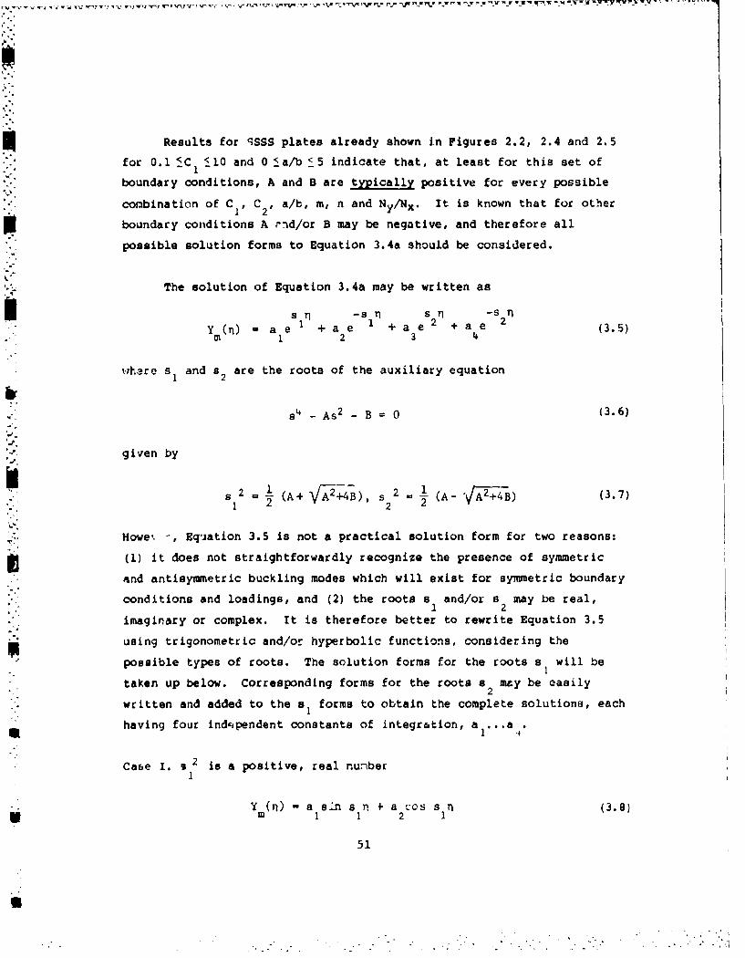
-. 7
Results for qSSS plates already shown in Figures 2.2, 2.4 and 2.5
for 0.1 _C <10 and 0 _a/b _5 indicate that, at least for this set of
boundary conditions, A and B are typically positive for every possible
combination of C1 , C2 , a/b, m, n and Ny/Nx. It is known that for other
boundary conditions A nid/or B may be negative, and therefore all
possible solution forms to Equation 3.4a should be considered.
The solution of Equation 3.4a may be written as
s rl -s 1 s 2 Y -s 2 1Y(n) a e51 + a e 1 + a e + a e2 (3.5)
m 1 2 3 4
whare s 1 and s 2 are the roots of the auxiliary equation
- As 2 - B = 0 (3.6)
given by
2 = (A+ V+4B), s 2 '(A- ( ) (3.7)~ 22 2 Y
Howe' -, Equation 3.5 is not a practical solution form for two reasons:
(1) it does not straightforwardly recognize the presence of symmetric
and antisymwetric buckling modes which will exist for symmetric boundary
conditions and loadings, and (2) the roots a and/or s may be real,1 2
imaginary or complex. It is therefore better to rewrite Equation 3.5
using trigonometric and/or hyperbolic functions, considering thepossible types of roots. The solution forms for the roots a will be
taken up below. Corresponding forms for the roots a may be easily2
written and added to the sa forms to obtain the complete solutions, each
having four indqpendent constants of integration, a ... a_,.
Case 1. 9 2 is a positive, real numberI
Y (9) - a sin s n * a 2.cs a n (3.8)* 1 1 2 (
51
U

Case II. s 2 is a negative, real number
Y (n) - a sinh s- n + a cosh s Ii (3.9)In 1 1 2 \
where 2 --s 2 (3.10)a 1 1
22In addition, s and s may be complex (4B is negative, and greater1 2
than A2 in magnitude). In this case the solution of Equation 3.3 is
more complicated, involving the products of trigonometric and hyperbolic
functions. These cases are the ones having significant practical value.2The case a, a 0 arises only in very special circumstances. It yields
repeated roots and a solution form Ym(n) a I+ n which can be
approached as closely as desired in numerical computations with ' e
forms en by Equations 3.8 or 3.9. Similarly, the case when s (but2
not 9I) is a pure imaginary number requires A - 0, which can also arise
only for certain special combinations of parameters, and may be
approached as closely as desired by taking small values of A with the
"olution forms given above.
As already mentioned, no proofs are known to exist which enable
one to determine a priori the correct solution form for a particular
problem. For example, it is well known for isotropic plates (i.e.,
C1 - C2 1 1) that the complete solution form2m
Y (n) "a sin s n + a cos S n + a sinh sln + a cosh s (3.11)Mi 2 1 3 4 2
2 2 - _6 2 is applicable to a wide range of problems. However, to be2 2
certain that this solution is correct for a paLticular set of para-
meters, one must verify that sa 2 and ,2 are both positive after the
elgenvalues (nondimensional buckling parameters) for the problem are
found.
U52

3.2. SCSC
A plate having two opposite edges simply supported (S) and the
remaining two clamped (C) is shown in Figure 3.1. The important case of
uniform biaxial loading (a., qy constant, rxy - 0) is depicted in
Figure 3.1, although more general stress distributions are possible.
For boundary conditions and inplane stress distributions which possess
two-fold symnetry, as in the present case, it is convenient to use the
xy-coordinate system shown, whereupon the boundary conditions become:
Along x O,a W W M - 0 (3.12a)x
Along y -+b/2 W . 2 y 0 (3.12b)'aU
All buckling modes will be either symmetric or antisymmetric with
respect to the symmetry axes of the plate. Thus, the solution form
shown previously in Equation 3.11 may be separated, and the displacement
functions may be written as:
Symmetric modes: V 2Y n _x (3.13a)W(,) a cos -+ a cosh sn-
2 b b a
Antisymmetric modes: w(X,-) a sin - + a s (313b)b 3 a
Substituting Equations 3.13 into Equations 3.12b yields, for nontrivial
solutions:
Synmetric modes: co - cosh T
-a - 0 (3.14a)-8sin -sn1 2 2 2
Antisymmetric modes: sin --
s insin 0si 22 (3.14b)-0
SSCos 2S 2 a Coal.-
2 2 2
53
I ,,' ,,m• • ,,•-"r,. ,'' •• : ,"•••'-'• •':-' ''" •'"" • •': ' ' ""

+ 0t/ t t/f t / / // /
ICm
+ I
I -
Figure 3.1. SCSC plate with uniform, biaxial stresses.
54
IW

Expanding the determinants given by Equations 3.14 yields the character-
istic equations:
Symmetric modes: s tan - + s 2tanh - 0-- ( 13.15a)
;2ssAntisymmetric modes: 8 tanh- s tan- 0 (3.15b)2. 2 2
The roots of these equations are the eigenvalues (nondimensional buck-
ling stresses) Kx obtained by using Equations 3.4 and 3.7 (with s 2 s -s 2).2 2
One procedure frequently followed in the literature does not take
advantage of the symmetries of the buckling modes (cf., [14,171). If,
for example, one uses a general solution for the displacement which is a
superposition of Equations 3.13a and 3.13b, and applies clamped boundary
conditions at y - 0 and y - b, one obtains a fourth order characteristic
determinant, instead of the two second order determinants given by
Equations 3.14. Expanding this determinant yields the characteristic
equation
aih 2s2 (cos s cosh s -) (3.16a)sin s 1sinh as2 1 2
- 22 81
Equation 3.16a may be factored into Equations 3.15a and 3.15b. It may
also be written as:
(cos a -cosh s )2+ (sin - sinh ; )(sin +- sinh a ) 2 0 (3.16b)1 2 22 1 22
Wittrick 157] showed if the ratio qy/ 0 x is sufficiently small, as
given by the inequality (2.28), Equation 3.3 is analogous to that of an
isotropic plate loaded in the same manner, and the results for SCSC
isotropic plates may therefore be applied to orthotropic plates. He
thus reasoned that if the parameter k is plotted vprsus X , as defined
in Equations 2.30 and 2.31, respectively, all results can be exhibited
55

by a single curve. This is shown as curve (b) of Figure 3.2, which
corresponds to the ends x - O,a being clamped and the sides y - O,b
being simply supported, with ax a constant And cy a -xy - 0. For the
case with the ends x - 0,a being simply supported and loaded, and the
sides y - 0,b being clamped (i.e., as shown in Figure 3.1), but not
loaded, Wittrick [57] presented curve (c) of Figure 3.2. However, for
this case k is defined not by Equation 2.30, but by
W h2 a x hbU 2(D 2+2D66) 3.7ID2 I IDI22
with C - 2.4, and X is defined by Equation 2.31 with ay set equal to
zero.
Brunelle and Oyibo [58,59] solved the problem of the uniaxially
loaded (Wx - constant, Oy - TXY a 0) SCSC orthotropic plate, and ex-
pressed the buckling parameter
a hb2k 0 x ( . 8
o w24DIJD22 (.8
in terms of a reduced aspect ratio parameter and a single orthotropic
stiffness parameter D*, as defined in Equation 2.53. This relationship
is plotted in Figure 3.3.
Lekhnitskii [17] used the energy method to obtain an approximate,
explicit formula for the critical buckling stress of a SCSC plate loaded
by uniaxial stress along the two simply supported edges (Ox constant,
a y = T -- 0). Assuming a buckling mode shape
w - - cos 2n-T ) sin mJx (m,n 1,2...)(39)a
results in the clamped boundary conditions at y * ± b/2, as well as the
56

'0 '--1110 - -J _ 1 ALL V.OGES CILAM,'EO
- -*I. fLENOS SIMPLY SUP•ORTED-
I _1SIOES CLA 1PE
7 -II
SI I I I
SUMPOATCO
.S! __/ I I !I
ill13-----------------I I 1! ..!.....I I.0 1 3
Figure 3.2. Single parameter buckling curves for uniaxial and biaxialloading, as determined by Wittrick
57

* 12-
I0 IL t.0
.8
6o .6.4
0.0
4-9
0 . - . . 5.0 6.0 70I0 I
?iue .. uk iyPaaetr frSbVothtopcplts
584
wvý-wit aj- A - v o wi

simply supported ones at x- 0,a, being satisfied exactly. Setting the
work done by the external forces during the buckling displacements,
(-VL), Equation 2.4, equal to the bending strain energy within the
plate, Equation 2.3, yields
axh ' 2 C1 + -n2. + 11 n4r (3.20)x D2 P:2 3 '2 3
where C1, C2 and r are given by Equations 2.16. Rewriting Equation
3.20 in terms of the nondimensional buckling parameter given in Equation
2.11, and recognizing that the critical buckling stress occurs for n - 1,
one obtains
Kx C1K 1 +8 16r2 (3.21)
This form is similar to the exact solution presented earlier in Equation
2.15 for the SSSS plate. Differentiating Equation 3.21 with respect to
r, and setting it equal to zero, one finds that the minimum value of Kx
occurs at
b 6 T C(3.22)b 16
and that the corresponding minimum values are given by
m8n - - + C (3.23)
S •2 -r',1 2
Comparing Equations 3.22 and 3.23 with Equations 2.17 and 2.18 one
observes that for the SCSC plate, not only are the minimum values of Kx
greater, as expected, but that compared with the SSSS plate, they occur
more frequently as a/b is increased. Further, the values of a/b at the
transition points where the buckling load is the same for mode shapes
having either m or m + 1 half-waves in the x-direction are given by
59
"o-

" M(M+l) (3.24)
which may be compared with Equation 2.19. The same result was obtained
by Brukva [82] by means of the Galerkin method.
For a long isotropic plate (a/b-- •, C, W C2 1 ) the approximate,¶
value of Kx/r 2 is found from Equation 3.21 to be 7.29, an error of ap-
proximately 4 per cent when compared to the exact value of 7 obtained
from Equations 3.15 or 3.16 [17].
The case when the loaded edge3 (x = O,a) are clamped and the
unloaded loaded ones (y - O,b) are simply supported (ox - constant,
Gy a -xy w 0) was also treated by Brukva [82]. He used the Galerkin
method along with the displacement function
W_ M1 sin _(3.25)
to determine the approximate buckling parameter for m - 1 (one half-
wave) to be
K- 4C (!-+ 2C, + 0.T7 (3.26)
a b)
whereas, for m = 2,3,...
K - (M_1) 4+(M+1) 4 (-yl+ 2C + 2 (a 2 (3.27)T = (m-l) 2 +(m+l) 2 a If + 2 (m_1) 2+(M+l) 2
The transit;on from one to two half-waves in the critical mode shape
occurs wher a/b - 1.67 C, . In general, the transition from m to m + 1
half-waves (for m + 1) occurs when
C (m4 +66M2 +l) + (a/b) 4 CI[(M+l)4+ 6(M+l)2+lI + (a/b) 4
,. (3.28)rn2+ j (M+1)2+ 1
60
.. ...... .
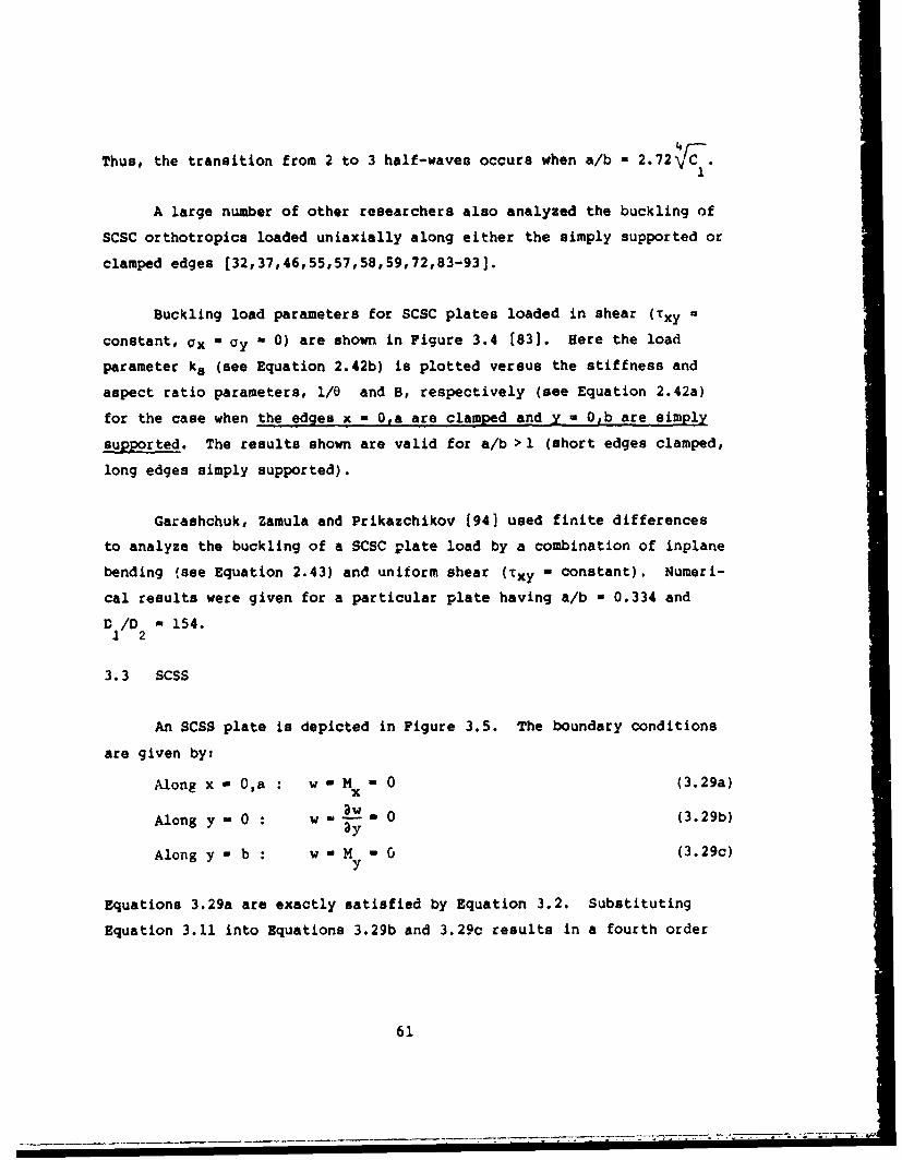
Thus, the transition from 2 to 3 half-waves occurs when a/b - 2.72 .
A large number of other researchers also analyzed the buckling of
SCSC orthotropics loaded uniaxially along either the simply supported or
clamped edges [32,37,46,55,57,58,59,72,83-93].
Buckling load parameters for SCSC plates loaded in shear (Txy
constant, ax W ay - 0) are shown in Figure 3.4 [83]. Here the load
parameter ks (see Equation 2.42b) is plotted versus the stiffness and
aspect ratio parameters, 1/0 and B, respectively (see Equation 2.42a)
for the case when the edges x - 0,a are clamped and y a 0,b are simply
supported. The results shown are valid for a/b > 1 (short edges clamped,
long edges simply supported).
Garashchuk, Zamula and Prikazchikov [94] used finite differences
to analyze the buckling of a SCSC plate load by a combination of inplane
bending (see Equation 2.43) and uniform shear (Txy - constant). Numeri-
cal results were given for a particular plate having a/b - 0.334 and
D /D 0 154.
3.3 SCSS
An SCSS plate is depicted in Figure 3.5. The boundary conditions
are given by:
Along x - O,a w - M - 0 (3.29a)
AloynOwa -0 (3.29b)
Along y - b : W " M . 0 (3.29c)3Y
Equations 3.29a are exactly satisfied by Equation 3.2. Substituting
Equation 3.11 into Equations 3.29b and 3.29c results in a fourth order
61
S. . ............. -. i"i""-

0
ODO cm-
CV.
6
0 0
u'
0 0
62-
,-4
'i-i
.i1J
I I i I I ., I I I :
wC
62H

I4%. I I
I blI I
. .I I"p i a I __
Figure 3.5. SCSS plate.
6
m
II•, 63
U'

characteristic determinant which, when expanded, yields the character-
istic equation [88]
s2 s= sl tanh s2 (3.30)
where s1 and i2 are parameters which are functions of D I/D22,
(D 2+2D 66/D 2 2 , a/mb, ay/ox and the buckling parameter Kx, and are
defined by Equations 3.4 and 3.7, with s 2 -s 2 . It is also seen to2 2
be the same as Equation 3.15b for the antisymmetric buckling modes of an
SCSC plate, for the antisymmetry conditions along the axis y = b/2 of an
SCSC plate are identical to the simply supported boundary conditions for
the SCSS plate. Finally, it may be observed that Equation 3.30 is the
same form which arises for the free vibrations of an SCSS plate [951.
Brunelle and Oyibo [58,59] solved the problem of the uniaxially
loaded (ox - constant, Cy - Txy - 0) SCSS crthotropic plate, and ex-
pressed the buckling parameter kO (see Equation 3.18) in terms of a
reduced aspect ratio parameter and a single orthotropic stiffness para-
meter and a single orthotropic stiffness parameter D* (see Equation 2.53).
This relationship is plotted in Figure 3.6.
SCSS orthotropic plates having the loaded edges both simply sup-
ported (ax a constant, 'y - Ixy - 0) were analyzed by Brukva [82]. The
Galerkin method was used along with the displacement function
Nmlx2n-i 2n+l
w a sin mx An - cos - nly) (3.31)
n-l,2
which satisfies simply supported conditions at x - O,a and clamped con-
ditions at y - O,b exactly. A first approximation obtained by taking
only one term of the summation (i.e., N - 1) yielded for the buckling
parameter Kx (see (Equation 2.11):
64
-~~~~~~~~~~t F- .- r n-rr..n,-r -- ''t C'C U

140 -
12.0-
10.0
8.0
6.0 1.06,.6
.2
.0
2.0-
0 1.0 po 0 3.0 4.0 5.0 6.0 7.0WI
Flquive 3.6. Uniaxial buck Lflg param-iters for SCSS corthotropic pl.ates.
65

KX iC (3.32)- + 2.5 C + 2.56 r 2
ITT 7 2
It waR determined that the minimum values of Kx occur at
a 0.788rV"7 •--(3.33)
with corresponding values of Kx:
j K (3.34)min = 3.2C,+ 2.5 C2
Transition points for buckling modes having m or m + 1 half-waves occur
ata O.788V i) 4
The results described above may be compared with similar (but exact) ex-
pressions describing the buckling cu:ves for an SSSS plate (see Section
2.1). An improved, second approximation was also obtainad [82] by
setting N v 2 ii, Equation 3.31. The Galerkin method then yields an
eigenvalue determinant of second order.
The case when ooe of the loaded sides is clamped (x - 0) and the
opposite one (x - a) is simply supported) (ax - con'itgfnt, ay a xy * 0,
was also treated by Brukva f82). The Galerklr. method, was used along
with the displacemort function
( 2m-1 2m+1 _ 33):w-.. ,.s2 .- co rx sin b3.35
which deter:jined th'3 aFl/oximate buckling parameter to bu (ccrrecting a
misprint):
06
" A
n !*~ .~

x, 0.25 4m++2(C22*)4 b 2 8202 (2m_1)2 +(2rn+l) 2 a C14+2C (2m-l)Z+ (2re+l)2
The ranges of aepect ratio having one or two half-waves in the critical
mode shape were found to be:
b 41-1 5 ' < 2.50Vc , for m - 2
b.54
Shuleshko [96] also developed an approximate formula .or deter-
mining the buckling loads of uniaxially loaded SCSS orthotropic plates.
This problem was also studied by Soni and Amba Rao [90J and by Massey
[97].
3.4. SCSF
As SCSF plate is depicted in Figure 3.7. The boundary conditiors
arit given by:
Along x O,a xw -0 (3.37a)aw
Alow-n 0 (3.37b)
Along Y y a V My (3.37c)
"Equatic.ns 3.29a are exactly satisfied by" 1quation 3.2. Substituting
Bquation 3.11 into Aqv-tions 3.37b and 3.37c yielda the characteristic
detev- nant I8s]
1' �jsinh ,zlfl2 A 1 B)(3.38)
COas t-cos
67
S.,VV'W,,Wt' 'i'W% - • 0. • - ,---'.' -¶ W

y
b I JI II blI II I
I o
II
Figure 3.7. SCSF plate.
68
-. 4 -. .. .. . .

2 M )2 1where A --2 +2D v (3.39a)s2 a/D2+2D66
12 66
1 =a s 2+ b r2D1 I (3.39b)I a ) 312 +D66 -
Vy is Poisson's ratio of the contraction of the orthotropic plate in the
y-direction due to ax, and a and s2 are as used previously (see
Sections 3.1 and 3.3).
Brunelle and Oyibo [58,59] solved the problem of the uniaxially
loaded (ax - constant, Cy a Txy - 0) SCSF orthotropic plate, and e.-
pressed the buckling parameter ko (see Equation 3.18) in terms of a
reduced aspect ratio parameter and two orthotropic stiffness parameters,
D* and c , where D* is defined by Equation 2.53 and E by
E D 12 (3.40)D12+266
Plots of ko are shown in Figures 3.8 and 3.9 for e - 0.2 and 0.3,
respectively.
This problem was also considered by Sotii and Amba Rao f90] as part
of a free vibration analysis of uniaxially loaded SCOF plates in the
special case wnen the frequency becomes zero.
3.5. 05SF
An 8SSF plate is depicted in Figure 3.10. The boundary conditions
along the edges x - 0,a are satisfied exactly by Equation 3.2. The
remaining conditions ares
69

3.5-
3.0-
2B
2.0ko
1.0.R
.6
1 .4
0.0
.5-
1.0 2.0 3.0 4.0 5.0 .65.0 70
Figure 3.0. Uniaxial. buckling parameters for scsF orthotropicPlatee (E 0.2).
70

3.5-
3.0-
2-5-
2.0-
1-5 0
1.0
1.0 - .4.20.0
.5r
01I1.0 .2.0 3.0 4.0 5.0 6.0 zo
Figure 3.9. Uniaxial buckling parameters for SCSF orthotropicplates (c 0.3).
71

i II I
I IlI I
L-----
Figure 3.10. SSSF plate.
72
* J° " "' ' " " "" .. . ' ---= " I L L _ . . " - - - =l= . " - ," ' -- l= ' " " " m ,• - ' m aw -

Along y - 0 : w =M = 0 (3.41a)Y
Along y - b : M - V = 0 (3.41b)y y
Substituting Equation 3.11 into Equations 3.41a and 3.41b yields the
characteristic equation (881
2 A 25 2 A 1a ! B sI•tn 2 (3.42)
(see Section 3.4 for notation).
Brunelle and Oyibo [58,591 solved the problem of the uniaxially
loaded (ax - constant, gy a Txy - 0) SSSF orthotropic plate, and ex-
pressed the buckling parameter ko (see Equation 3.18) in terms of a
reduced aspect ratio parameter and two orthotropic stiffness parameters,
D* and € (see Equations 2.53 and 3.40, respectively). Plots of ko are
shown in Figures 3.11 and 3.12 for e 0.2 and 0.3, respectively.
Holston [98] derived a special solution to Equation 3.1 for the
case ax constant, ay - 0 which is valid in the particular case when
axhb2 2 D13 (3.43)X Dax" (E = - -
22 22
It has a form containing constant and linear terms in y, as well as
hyperbolic functions. He also used the energy method to develop an ap-
proximate formula for the buckling loads, and pointed out an error in
two other relevant references (99,100].
This problem has also received some minor attention elsewhere
[32,90].
73
I~

3.5
.3.0
2.5
2.0
1.5
1.0
.5
.
.6
MJ0.0
2.0 3.0 4.0 5.o 6.0 7.0o 1 .0 4/ 1 5 22-.., , :b V a.
Figure 3.11. Uniaxial buckling paraUaeters for $SSF orthotropic
pLates ( 0.2).
74

3.5
3.0
1.5
2.0
".5
1..4
.80.0
..5. .......
4.
. .
0 2.0.. 4 .05. 60 .
~ig1r 3.2.U11aia4 buckling9 Pa"atfeter 0 or SSSV orthotropic
p~ g g e 3 . 2 . p l a t ts ( 0 .3 ) .
75
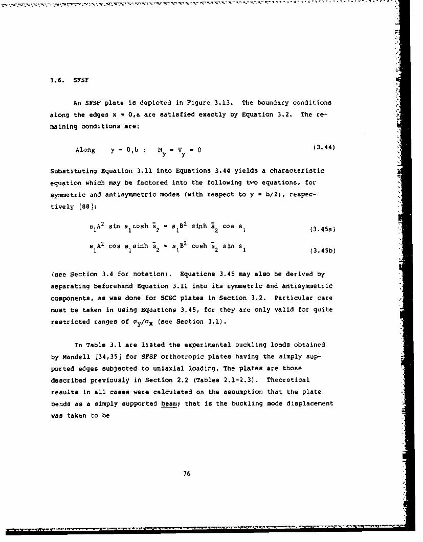
3.6. SFSF
p'.
An SFSF plate is depicted in Figure 3.13. The boundary conditions
along the edges x * O,a are satisfied exactly by Equation 3.2. The re-
maining conditions are:
Along y- O,b my V - 0 (3.44)y y"
Substituting Equation 3.11 into Equations 3.44 yields a characteristic
equation which may be factored into the following two equations, for
symmetric and antisymnetric modes (with respect to y - b/2), respec-
tively [881:
"SlA2 sin a cosh s s B2 sinh s cos s11 2 1 2 1 (3.45a)
"sA2 cos s sinh s2 B cosh -s sin s12 1 2 1 (3.45b)
(see Section 3.4 for notation). Equations 3.45 may also be derived by
separating beforehand Equation 3.11 into its symmetric and antisymmetric
components, as was done for SCSC plates in Section 3.2. Particular care
must be taken in using Equations 3.45, for they are only valid for quite
restricted ranges of ay/ax (see Section 3.1).
In Table 3.1 are listed the experimental buckling loads obtained
by Mandell 134,353 for SFSF orthotropic plates having the simply sup-
ported edges subjected to uniaxial loading. The plates are those
described previously in Section 2.2 (Tables 2.1-2.3). Theoretical
results in all cases were calculated on the assumption that the plate
bends as a simply supported beam/ that is the buckling mode displacement
was taken to be
76
__ °

yX
SY
I I
I. a l_ _
Figure 3.13. SFSF plate.
Table 3.1. Buckling loads (-N lb/in)for Mandell's SFSFXorthotropicplates
7Ploe Experimental Theoretical
201 11.3 12.5202 84.9 105204 10.8 12.7205 2.74 3.83206 5.26 6.92207 0.848 1.29404 199 215
"216**405 23.3 23.7
"23.6**
obtained by I.r..-• -Pthn4
77
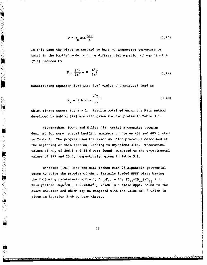
w = c x (3.46)m a
In this case the plate is assumed to have no transverse curvature or
twist in the buckled mode, and the differential equation of equilibrium
(2.1) reduces to
a•w 32w7-V =DX 3 (3.47)
Substituting Equation 3.46 into 3.47 yields the critical load as
T ZD 11(3.48)N • h- - 2
x X a2
which always occurs for in = 1. Results obtained using the Ritz method
developed by Ashton [42] are also given for two plates in Table 3.1.
Viawanathan, Soong and Miller [93] tested a computer program
designed for more general buckling analysis on plates 404 and 405 listed
in Table 1. The program uses the exact solution procedure described at
the beginning of this section, leading to Equations 3.45. Theoretical
values of -Nx of 206.5 and 22.6 were found, compared to the experimental
values of 199 and 23.3, respectively, given in Table 3.1.
Baharlou [101] used the Ritz method with 25 algebraic polynomial
terms to solve the problem of the uniaxially loaded SFSF plate having
the following parameters: a/b - 1, D /D - 10, (D +2D )/D u 1.11 22 12 66 22
This yielded -Nxa 2 /D - 0.9846i 2 , which is a close upper bound to the
exact solution and which may be compared with the value of r2 which is
given in Equation 3.48 by beam theory.
Wk
78
. .

3.7. Elastic Edge Constraints
Consider a plate with uniaxial loading (ac - constant, ay a tXY -
0) having three sides simply supported, with the fourth side (y - b)
elast'cally constrained against rotation (SSSE). Along y - b, the
conditions to be satisfied are:
w 0, my k (3.49)
where kr is the rotational spring stiffness per unit length of edge.
Following the same procedure described in the preceding sections,
Shuleshko [88] showed that the following characteristic equation
results:
4k b(S2 + s 12) sin s sinh a2 = r (s Cos I slnh s2 - s 2sin a cosh s (3.50)
22
For the case of a uniaxially loaded plate having two sides
(x - 0,a) simply supported, one (y - 0) free and the fourth (y - b)
elastically restrained against rotation (SPSE), Shuleshko 188] deri~evJ
the characteristic equation:1
(2+ a2) sa i s 1cosh , - A sinh s (3.51)1~~ ~ 2 A nB 28i ,
4k rD2 b zA s o 2-A, sinh s in sB+ II+-s cosh -9Cos 8 + 28a asih
D 2 [ABA) 1 2 2 1 1 2- 2A 1 B1
(after changing the sign of the 2sisa term and adding a bracket to make
the equation consistent with Equation 3.38).
The SCSE plate yields the characteristic equation [88):
79

s 2 2=2 .
•2 SICOS Ss sh s2 - s 2sin slcosh ss2) (3.52)
4k b s1 -8
C - cosh s)2 + sin s - sinh s2 sint -' 2 sinh aD s-2 c2) Ss , 1 S2)]
The SESE plate subjected to uniaxial loading (ax = constant,
a- Txy = 0) was studied by Libove (72]. The exact solution procedure
described above was used to obtain the following formula for the
buckling loads:
-a hb2 _________
T2 1DI2+2D66) a ) D 12+2D 1 2 + f( 3.53)66
where f is a function of the spring stiffness parameter krb/D2 and the1
parameter ta/mb)- 2 2/(D 12 +2D6 6 ), and is plotted in Figure 3.14. Several
others have also examined this problem (102-105].
Sakata 1106] used the reduction method to analyze the buckling of
continuous orthotropic rectangular plates having the edges x - 0,a
simply supported, y - 0,b elastically supported with intermediate
supports located at lines y - constant. Along the supports the
condition w - 0 ib prescribed. The problem is solved using exact
solution functions given by Equations 3.2 and 3.11, with continuity of
displacement, slope and moment enforced across the supports. Numerical
buckling results for uniaxial and biaxial loading conditions were calcu-
lated for the case of SSSS edge conditions, with a/b a 0.5, (D +2D )/D12 66 22
a 0.25 and intermediate supports located at y - 0.3b and 0.7b (see
Figure 3.15). These are displayed in Table 3.2, where the variation of
Kx/• 2 (Equation 2.11) with ayhb 2 /IT2 D2 2 and D1 I/D 22 are seen. This
problem was also dealt with by Nowacki J107].
80
* .* -

10-
'•.011 T
-001 0II10{'•,) oil4 2)i
Figu:e 3.14. The function f1 to be used in Equation 3.53 for theuniaxial buckling of SESE orthotropic pjA.tes.
81

y
-0o3
0-3b
I TI
Sr I- I :
I I
aI 05I I 0-bbI II I
I III
, I I 0'S
_, ~o--05b
Figure 3.15. Continuous SSSS plate with intermediate supports aty =0.3b and 0.7b; a/b a 0.5.
Table 3.2. Critical buckling parameters Kx/hf 2 foran SSSS plate with intermediate supports(see Fig. 3,15).
1) C hb2/ff2D11 Y 22Z. 22 0 5
A • _ . ri.]
1 0 15.425 24.904 34.203
2:0 19.425 28.904 38.203
82
'I -- ý-r A -'CA r A 9 Z

CHAPTER IV. ORTHOTROPIC PLATES - OTHER EDGE CONDITIONS
In the preceding two chapters, orthotropic plates having two
opposite edges simply supported were considered, which were seen to
include six possible combinations of classical boundary conditions,
along with some additional cases where the remaining two edges were
elastically supported. It was also seen that exact solutions for
buckling problems were possible when the loading consisted of uniform
normal stresses. The remainiing classical problems may be represented by
15 distinct arrangements of edge conditions [108]. Following the
identification system set forth in Chapter I, these may be listed as:
CCCC, CCCS, CCCF, CCSS, CCSF, CCFF, CSCF, CSSF, CSFF, CFCF, CFSF, CFFF,
SSFF, SrFF and FFFF. As will be seen below, the CCCC plate has received
a great deal of attention, whereas relatively little has been done with
the other cases. For none of these problems are exact theoretical
solutions possible, even in the case of uniform normal buckling stresses,and approximate methods must be used.
Dickinson [109] generalized a method which was developed by
Warburton [110] to determine the free vibration frequencies of isotropicrectangular plates having all 21 possible combinations of boundary con-
ditions to orthotropic plates subjected to uniform inplane stresses.
The meLhod is a development of one first suggested by Rayleigh [1111,
whereby a reasonable mode shape is assumed and substituted into the
proper energy functionals to determine the eigenvalue for the problem.
In the case of buckling the total potential function is defined by
Equations 2.2-2.4, and setting V - 0 determines the buckling load. The
mode shapes are assumed to be the products of the eigenfunctions of
vibrating beamsl for example, for a CSCF plate, the products of CC and
FF beam functions would be used. In addition to satisfying the boundary
83

conditions for the plate (although not exactly in the case of a free
edge), the eigenfunctions are orthogonal over the plate dimensions, which
reduces the numerical complexity of the calculations. The method has
been demonstrated to be quite accurate for plate vibrations [112], but
should be less accurate for plate buckling, for beam buckling MAde
shapes are somewhat different than beam vibration mode shapes (except
when both ends are simply supported). Following the procedure described
above, Dickinson [109] arrived at the following general formula for the
determination of plate buckling loads:
I~G xLý Ga b~}y k/\ 2b) D
2(D 12+2D 66) D (4.1)+ 12x66+ ±4 D6-6(JxJ - HHy)
D22 22
where Kx is defined by Equation 2.11, Gx, Hx and Jx are functions
determined from Table 4.1 according to the conditions at x - 0 and x - a,
and Gy1 Hy and Jy are obtained by replacing x and y and m by n in Table
4.1. The integers m (and n) used in Table 4.1 are not the half-wave
numbers used in previous chapters, but rather the number of nodal lines,
including clamped or supported edges, perpendicular to x (or y). If
m-l in Table 4.1 is replaced by a (and n-i by n) then, in the case of
SSSS boundary conditions, Equation 4.1 agrees exactly with Equation 2.24
for the buckling dule to biaxial loading.
Figure 4.1 (taken from [8]) is a useful set of curves governing
the buckling of isotropLc plates which are uniaxially loaded, and have
the loaded edges either clamped or simply supported. The other two
edges are either CC, CS, CF, SS and SF (i.e., all combinations except
FF). Variation of the buckling parameter KX/7 2 (see Equation 2.11) with
a/b is seen, along with the number of longitudinal half-waves in the
81
84 '
- ~ ' %' ~- -

Table 4.1. Coefficients in Equations 4.1 for buckling loads of plateswith arbitrary boundary conditions.
Boundur.onditdam. m H,
ECBS -.-.............- 2,3,4, ... n-I (,n-i), (,,-i),SSb ....... ....... ,-•---C A ---------------- 2 1 .508 L 248 L 248
1 ---- 1 n- 1)'[1- (in- (_1 •21b... . .. . .. . , 4, 5, . 2 2 2 -_
-F a----------------- 0 0 0 01 0 0 12/0'2 L 506 L 248 6.017
LFb------ .. - )[ 21).] (m6Y7~m~t.................. ,4, 5 .... RS2 (in- _)'[1,(_C )] ( 2- )' 1÷( 8.2 2)
cc&------------------ 23,SP. ................ • ,, . . . • ( -)[ , . _)[F a .----------------- 3,.. 1 0 0,
•, ............. M,_! .. . . • . _'• ..
a .597 -0.0870 0.471-c2 ................. L 494 L 347 & 284
-*,z-_ 0.,_, ............. 3,4,5, . ., i-n' ( _• . ,. 2• •
85 2
85

16K A
I cSS J FI.- D .
SSI0 s 8
I' \LOADED EDGESCLAMPED
LOADED EDG SML
J F SUPPORTED
2
0 6
a/b
Figure 4.1. Buckling parameters for uniaxiallY loaded isotropicplates.
86

mode shape for each case. While the curva-s are only for a particularcase of an orthotropic plate (D1 /D 1, (D +2D )/D a 1), they are
as 22 12 66 22
useful in predicting trends in critical loads and mode shapes as
boundary conditions are varied. The data shown previously in Figure 3.2
is consistent with Figure 4.1.
4.1. CCCC
Brunelle and Oyibo [58,59] solved the problem of the uniaxially
loaded (ox - constant, ay - Txy 0) CCCC orthotropic plate, and ex-
pressed the buckling parameter ko (see Equation 3.18) in terms of a
reduced aspect ratio parameter and a single orthotropic stiffness
parameter D* (see Equation 2.53). This relationship is plotted in
Figure 4.2.
Wittrick 157] showed that the uniaxial buckling load for CCCC
orthotropic plates can be determined from the single curve arising from
isotropic plate analysis. This is shown as curve (d) in Figure 3.2.
For this graph, k is defined by Equation 3.17, with C - 2.46, and X is
defined by Equation 2.31 with ay set equal to zero.
The uniaxially loaded CCCC plate was also analyzed by Brukva [82].
The Galerkin method was used along with the displacement function
M CBr-i M+l - 27ry) (4.2)a -a a-- x) (1 Cosb
to determine approximate formulas for the buckling parameter Kx (see
Equation 2.11). For one half-wave (m - 1) the value was found to be
K b 2 84 4() cl+ -C, + 4Q.. (4. 3)
whereas for m - 2,3,...
87
- . . .

12.0-
10.0 S
8.0-
A A.8
A .2
4.0 AlAntisymmetric buckling
I S: Sym~metric buckling
2.0-
0 1.0 2.0 3.0 4.0 &.0 6.0 TO
Figure 4.2. Uniaxia]. buckling parameters for CCCC orthatropic
88

Kx (m-)4 + ( b\l) 4 8 10.66 2
" (m-1)2+ (rM+1) 2 32 (m-) 2+(m+1) 2 b
The ranges of aspect ratio having one, two or throe half-waves in the
critical mode shape were found to be:
a 4fb< I.ii , for m-1
i.i1. < A < 1.78 , for m - 2
1.78 T< • < 2.481 , for m - 3
Baharlou JIOJ used the Ri-z method with 25 algebraic polynomial
terms to analyze CCCC orthotropic plates having the following para-
meters: a/b - 1, C1 - 10, C2 a 1 (see Equations 2.16). He obtained
buckling parameters for uniaxial compression, biaxial hydrostatic
(ax M Cy) compression and uniform shear. These are seen in Table 4.2,
where Kx and Ks are as given by Equations 2.11 and 2.35a, respectively.
The values given are all close upper bounds to the exact solutions.
A number of other researchers have also investigated the buckling
of uniaxially loaded, CCCC orthotropic plates [32,83,85,87,91,112-114].
Housner and Stein 168,69] used a finite difference energy method
(see description in Section 2.3) to analyze the buckling of CCCC plates
subjected to uniform shear stress. Numerical results for buckling para-
meters ks are given in Table 4.3 for wide ranges of the aspect ratio and
stiffness parameters B and e, respectively, which are defined in
Equations 2.40. These data are also plotted in Figure 4.3, and may be
compared with results for SSSS plates given earlier in Table 2.6 and
89
,•% -- ,• .4 ,=.r.. • -••..... •..-..-,•. • . . --- ,-% d .,'m .-- ,- - - ", - • •4 '" - " " - - --

Table 4.2. Buckling parameters for CCCCorthotropic square plates;C-10O, C2"I.
Uniaxial Hydrostatic Shearloading loading loading
K K
Tr2 IT2 1T2
46.25 16.75 47.03
90
-i . - -- ' - - i ' '- -- " - - --. . . ."i '' 'i . - " - . " -"9 0.

Table 4.3. Shear buckling parameters k. for CCCCorthotropic plates (see Equations 2.40
for defiaitions).
p B ks 8 B k
0.2 3.0 32.56 1.25 1.0 13.87
0.8 26.31 0.8 11.680.6 22.21 0.6 10.460.4 18.91 0.4 9.390.2 17.34 0.2 8.800.1 17.31 0.1 8.980 17.13 0 8.45
0.4 i.0 21.63 1.667 1.0 12.91
0.8 17.92 0.8 10.900.6 15.43 0.6 9.800.4 13.62 0.4 8.860.2 12.64 0.2 8.340.1 12.89 0.1 8.580 12.51 0 7.93.
0.6 1.0 17.86 2.5 i.0 11.930.8 14.89 0.8 10.110.6 13.06 0.6 9.070.4 11.60 0.4 8.310.2 10.64 0.2 7.840.1 10.95 0.1 8.120 10.69 0 7.32
0.8 1.0 15.94 5.0 1.0 10.940.8 13.34 0.8 9.310.6 11.84 0.6 8.330.4 10.55 0.4 7.740.2 9.99 0.2 7.33C.1 10.16 0.1 7.660 9.63 0 6.72
1,0 1.0 14.81 c 1.0 9.920.8 12.44 0.8 8.48
0.6 11.08 0.6 7.57u.4 9.89 0.4 6.97
0.2 9.2/ 0.2 6.790.1 9.11 0.1 7.17
0 8.99 0 6.11
91
g

0 "1122
D3
24 0.2 .
4.
20
.6
~16
z -1.25
C3M 12 2.55
0 .2 .4 .6 .8 1.0
b */DI,
Figure 4.3. Shear buckling parameters for CCCC orthotropic plates.
92

Figure 2.8. It is seen that the critical mode shape changes occur more
clearly for CCCC than for SSSS plates.
Another set of useful results for the CCCC plate loaded in shear
was obtained by Smith [75]. This is shown in Figure 4.4. Here the
load parameter k. (see Equation 2.42b) is plotted versus the stiffness
and aspect ratio parameters, 1/0 and B, respectively (see Equations
2.42a). The case of shear loading was also studied by a few others [32,
72,115,116].
4.2. CCCS
CCCS orthotropic plates having the edges x w O,a subjected to a
uniaxial loading (vx - constant, oy a Txy - 0) were analyzed by Brukva
[82]. The Galerkin method was used along with the displacement function
w ( cosr-1- - x Cos - (4.5)a a2b2)
An approximate value for the buckling parameter Kx (see Equation 2.11)
was determined for m a 1 (one half-wave) to be
K X 4C-+ 2.5C + 1.92(1) (4.6)t7 " 2
whereas for m - 2,3,...
K =(m_1)4+(m+1)4 'bt' 2 5.1 'a'2-2 (m_]) 2+(r-l) 2 C + 2.5C + (4.7.)T 2 a 1 2 (M-l) 2+(M+l) 2
The ranges of aspect ratio having one or two half-waves in the critical
mode shape were found to be:
93

(00S U)Ad
V' 'I . O " c
944
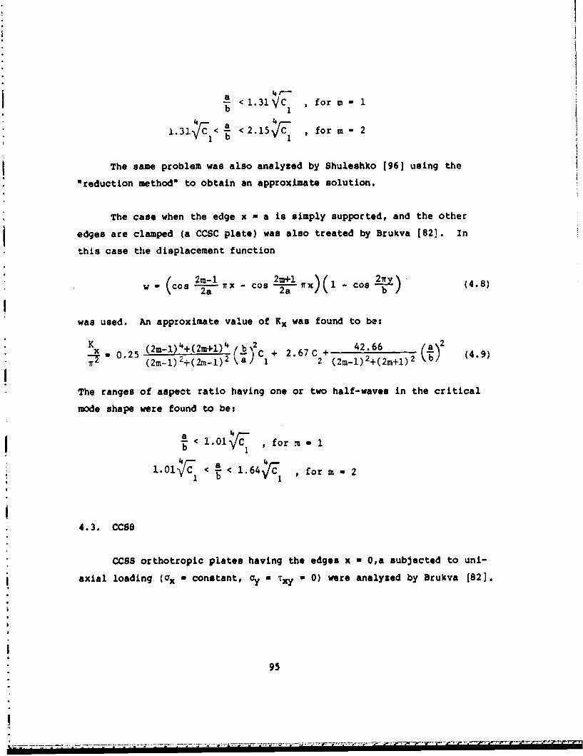
4(--
b< 1.31VC , for m- 1
1.31. < A < 2.15TI, , for m = 2
The same problem was also analyzed by Shuleshko [96] using the"reduction method" to obtain an approximate solution.
The case when the edge x - a is simply supported, and the other
edges are clamped (a CCSC plate) was also treated by Brukva [82]. In
this case the displacement function
w2(cos nlx - Cos 2(a 1 - cos )b (4.8)
was used. An approximate value of Kx was found to be:
*K x(2m-1) 4+(2-M+1) 4 (b,%2 .7 42.66a20.25 2+(2M + 2.67C + (4.9)
* (2m1) L+(2ml) 2 ka) 1 2 (2m-l) 2+(2m+1)2kb
The ranges of aspect ratio having one or two half-waves in the critical
mode shape were found to be:
-< 1.01 ,C for u-n
44. 1.01"C/ < < 1.64 , for m n 2
4.3. CCSS
CCSS orthotropic plates having the edges x - O,a subjected to uni-
axial loading (ax - constant, Cy 0 TX y 0) were analyzed by Brukva (82].
95
-a

The Galerkin method was used along with the displacement function
w (os2m-oC 2m+l.) (Lo - CosB (4.10)
-2a•-x - 2a 2b 2b
An approximate value for the buckling parameter Kx (see Equation 2.11)
was determined to be:
K ~(2m-1)4%(2m+1) 4 (b 2 2C()--. 0.25 (2+ C + 2.5C + .5 (4.11)
T2(2m)2+(2m+l) 1 2 (2m-1) 2 +(2m+1)2 b
The ranges of aspect ratio having one, two or three half-waves in the
critical mode shape were found to be:
a < 1.21C , for m - 1
1.21TCJ < A < 1.97 ýC , for m - 2
4 41.97 < A < 2.76 Ic , for m - 3
4.4. Other Edge Conditions
The case of the CVCP plate subjected to uniaxial compression along
the clamped edges was examined by Viswanathan, Soong and Miller [92]. A
set of experiments was conducted on 24 specimens made of combinations of
titanium, adhesive and boron composite material. Theoretical values
were obtained by taking results for the SPSY plate and multiplying by
four (as in isotropic beam theory). Difficulty in experimentally
achieving perfect clamping conditions also resulted in the use of a
"modified length" between the clamped edges in an effort to achieve
better correlation between experiment and theory.
96

Simitses and Girt [117] analyzed SSSS plates having rotational con-
straints along all four edges for uniaxial loading conditions ( a
constant, Oy xy a 0). Let the rotational spring stiffness per unit
length along the edges x - 0,a be Oi, whereas along y - 0,b it is a2
(corresponding to kr in Equation 3.49). The modified Galerkin method
(i.e., using additional line integrals the edges to account for the
moment conditions not being exactly satisfied) was used, with transverse
displacements assumed in the form
(xy) - a sin M-x sin -ym a b
(4.12)
+ bI Cos -Ij- - Cos --(i-)] (1 Cos 1a)
i-a
The modes separated into symmetric and antisymmetric classes with
respect to the x-direction, and numerical results were obtained [117]
with third order determinants (i.e., two terms retained in the summation
shown in Equation 4.12). Numerical results for the nondimensional
buckling parameter Kx(D /D22 )/71 2 (see Equation 2.11) are presented in
Table 4.4 for plates having Gxy/Ex - 0.4, vxy u 0.7, for various values
of Ex/Ey(O DII/D 2 2), a/b, $la/D1l and 02a/D 11 . The plate stiffness
ratio 2(D 2+2D 66)/D11 is related to the elastic constants by
12 66 (4.3a
D12+2D66 + 2 GYy (4.13a)D YX E E xxx x~x
(4.13b)E v "E vxyx TY xy
The numerical data given is aimed at application to folding cartons made
of paperboard. The displacement functions used above were criticized by
9
U
• ; 97
-U#

Table 4.4. Buckling parameter Kx(Dll/D 2 2 )1T2 for uniaxially loadedSSSS orthotropic plates having rotational edge constraints.(Gx /E -0.4, v -0.7). Numbers in parentheses are numbersof L.ifx-waves i~xthe x direction.
(a) 1 a/D1 1 = 0
D 02 a/D 1 1D11 a "
D2 2 b 0 1 10 100 1000
0.5 5.816(1) 6.017(1) 7.629(1) 10.364(3) 15.466(3)1.0 3.004(1) 3.383(1) 5.286(1) 6.776(3) 7.259(3)
4.0 1.5 2.761(1) 3.302(1) 4.739(2) 6.107(l) 6.207(1)
2.0 3.004(1) 3.195(2) 4.203(2) .5.254(2) 5.428(2)
0.5 5.889(1) 6.089(1) 7.703(1) 10.558(3) 15.640(3)1.0 3.139(1) 3.520(1) 5.487(1) 7.247(3) 7.664(3)
3.0 1.5 3.000(1) 3.550(l) 4.857(2) 6.444(2) 6.808(2)
2.0 3.139(2) 3.331(2) 4.397(2) 5.626(2) 5.836(2)
0.5 6.033(1) 6.233(1) 7.850(l) 10.946(3) 15.990(3)1.0 3.408(1) 3.791(1) 5.875(1) 8.097(1) 8.460(1)
2.0 1.5 3.477(1) 4.039(1) 5.088(2) 6.893(2) 7.333(2)
2.0 3.408(1) 3.602(2) 4.763(2) 6.347(2) 6.630(2)
0.5 6.466(1) 6.666(1) 8.290(1) 12.113(3) 17.036(3)
1.0 4.216(1) 4.605(1) 6.961(1) 10.139(l) 10.698(1)1.0 1.5 4.556(2) 4,704(2) 5.755(2) 8.189(2) 8.886(2)
2.0 4.216(2) 4.413(2) 5.663(3) 7.619(3) 8,375(3)
98
. . .. . . . .

Table 4.4. (Continued)
(b) {1 a/D4 1 - 1
a/DD b 0 1 10 100 1000
22
0.5 7.299(1) 7.466(1) 8.812(1) 11.219(3) 15.622(3)
4.0 1.0 3.383(1) 3.716(1) 5.399(1) 6.810(3) 7.259(3)1.5 2.935(1) 3.439(1) 4.822(2) 6.107(1) 6.207(1)
2.0 3.102(2) 3.282(2) 4.235(2) 5.255(2) 5.428(2)
0.5 7.372(1) 7.539(1) 8.888(1) 11.412(3) 15.796(3)1.0 3.520(1) 3.856(1) 5.607(1) 7.277(3) 7.664(3)
3.0 1.5 3.175(1) 3.692(1) 4.943(2) 6.448(2) 6.808(2)
2.0 3.237(2) 3.419(2) 4.433(2) 5.627(2) 5.836(2)
0.5 7.518(1) 7.686(1) 9.039(1) 11.797(3) 16.144(3)
1.0 3.791(1) 4.134(1) 6.010(1) 8.101(1) 10.698(1)2.0 1.5 3.653(1) 4.189(1) 5.180(2) 6.898(2) 7.333(2)
2.0 3.237(1) 3.692(2) 4.806(2) 6.348(2) 6.630(2)
0.5 7.956(1) 8.124(1) 9.493(1) 12.951(3) 17.184(3)
1.0 4.605(1) 4.961(1) 7.132(1) 10.145(1) 10.698(1)1.0 1.5 4.731(2) 4.871(2) 5.862(2) 8.197(2) 8.886(2)
2.0 4.316(2) 4.507(2) 5.731(3) 7.627(3) 8.375(3)
99

Table 4.4. (Conetinued)
(c) $ a/D 11 10
DII a _2 ./1
D2 2 b 0 10 100 1000
0.5 13.580(l) 13.622(i) 13.969(l) 14.994(3) 16.554(3)
1.0 5.286(1) 5.399(l) 6.058(l) 6.999(3) 7.264(3)4.01.5 4.057(1) 4.331(1) 5.346(2) 6.110(1) 6.207(1)2.0 3.766(2) 3.873(2) 4.472(2) 5.263(2) 5.428(2)
0.5 13.681(1) 13.722(1) 14.072(1) 15.172(3) 16.722(3)
1.0 5.487(1) 5.607(,1) 6.318(1) 7.417(l) 7.668(3)3.0 1.5 4.353(1) 4.657(1) 5.496(2) 6.484(2) 6.808(2)
2.0 3.923(2) 4.037(2) 4.700(2) 5.637(2) 5.836(2)
0.5 13.880(1) 13.923(1) 14.278(1) 15.527(3) 17.057(3)1.0 5.875(1) 6.010(1) 6.823(1) 8.132(1) 8.460(1)
2.0 1.5 4.913(1) 5.265(l) 5.788(2) 6.941(2) 7.334(2)
2.0 4.227(2) 4.352(2) 5.128(2) 6.361(2) 6.630(2)
0.5 14.476(1) 14.520(1) 14.892(1) 16.590(3) 18.060(3)
1.0 6.961(1) 7.132(1) 8.228(1) 10.194(1) 10.698(1)1.0 1.5 5.920(2) 6.003(2) 6.609(2) 8.264(2) 8.887(2)
2.0 5.095(2) 5.243(2) 6.241(3) 7.691(3) 8.376(3)
100
• ".' - -. .-. o- . ....- ...-..- -..- ,-.- -.. . -. .°. -_... . . . .:': .: 'a. _: :.- ,; -. ' .. ,•; -..- -. . . - _• . , • . • 5 . -. , . . . - _ - .. _, _ . . . . -. . - . -..• , , _. _. , .- ..- -'

Table 4.4. (Continued)
(d) 81a/D1 1 100
D8 aIDD 02 aD11
D22 b 0 1 10 100 1000
0.5 17.913(1) 17.913(l) 17.921(1) 17.986(1) 18.105(3)
1.0 7.028(1) 7.031(1) 7.054(1) 7.176(1) 7.292(3)4.0 1.5 5.845(1) 5.857(1) 5.938(1) 6.132(1) 6.207(l)
2.0 5.077(2) 5.084(2) 5.134(2) 5.317(2) 5.429(2)
0.5 18.056(1) 18.057(1) 18.065(1) 18.130(1) 18.261(3)
3.0 1.0 7.388(1) 7.391(1) 7.417(1) 7.552(l) 7.691(1)
1.5 6.456(1) 6.470(1) 6.528(2) 6.656(2) 6.812(2)
2.0 5.412(2) 5.420(2) 5.481(2) 5.702(2) 5.837(2)
0.5 18.343(l) 18.344(1) 18.352(1) 18.419(1) 18.572(3)
1.0 8.097(1) 8.101(l) 8.132(1) 8.295(1) 8.464(1)2.0 1.5 6.964(2) 6.967(2) 6.994(2) 7.149(2) 7.339(2)
2.0 6.055(2) 6.066(2) 6.149(2) 6.450(2) 6.632(2)
0.5 19.203(1) 19.204(1) 19.212(1) 19.284(1) 19.505(3)
1.0 10.139(1) 10.145(1) 10.194(1) 10.446(1) 10.703(1)1.5 8.300(2) 8.305(2) 8.348(2) 8.593(2) 8.895(2)
2.0 7.698(3) 7.704(3) 7.752(3) 8.030(3) 8.385(3)
101

Table 4.4. (Continued)
(e) a a/D11 1000
82 aIDi 1D11 a
D2 b 110 100 1000
0.5 18.519(1) 18.519(l) I 18.519(1) 18.S20(1) 18.527(1)
1.0 7.298(1) 7.298(1) 7.298(1) 7.301(1) 7.313(1)4.0 1.5 6.181(1) 6.181(1) 6.182(1) 6.190(1) 6.210(1)
2.0 5.408(2) 5.408(2) 5.409(2) 5.415(2) 5.435(2)
0.5 18.670(1) 18.670(1) 18.670(1) 18.671(1) 18.678(1)1.0 7,688(1) 7.688(1) 7.688(1) 7.691(1) 7.705(1)
3.0 1.5 6.814(1) 6.814(2) 6.815(2) 6.817(2) 6.831(2)
2.0 5.812(2) 5.812(2) 5.813(2) 5.820(2) 5.844(2)
0.5 18.972(1) 18.972(1) 18.972(1) 18.972(1) 18.979(1)
2.0 1.0 8.460(1) 8.460(1) 8.460(1) 8.464(1) 8.481(1)1.5 7.342(2) 7.342(2) 7.342(2) 7.345(2) 7.362(2)2.0 6.598(2) 6.598(2) 6.599(2) 6.609(2) 6.641(2)
0.5 19.875(1) 19.875(1) 19.875(1) 19.876(1) 19.884(1)
1.0 10.698(1) 10.698(1) 10.698(1) 10.704(1) 10.729(1)1.C 1.5 8.899(2) 8.899(2) 8.900(2) 8.904(2) 8.932(2)
2.0 8.386(3) 8.386(3) 8.387(3) 8.393(3) 8.428(3)
102 N.
S. . . " - _ - - = . . .. .. . .. . . . . .. . . . .. .? " • • .: " • • = = "" , . . . . " " " " .. - r., h- .••_. . . .. - ."

Crouzet-Pascal [118] who said they are only valid when all edges are
either simply supported or clamped. The authors did not agree [1191 but
indicated that the accuracy of the results is questionable only when
and 2 differ from each other by two orders of magnitude or more.
103
.............................

CHAPTER V. ANISOTROPIC PLATES
Consider next composite plates whose bifurcation buckling is governed
by the differential equation (see Appendix);
W W •2w 4D1 ~ 4D 1 6 +y 2(D 1 2+2D 6 6)=3y+ D D 3Y
= h(° ý + 2ry----- + ay (5.1)
that is, terms containing D and D2 6 , which involve the bending-twisting16 26
coupling, are added to Equation 2.1. This is the classical equation for
the buckling of an anisotropic plate. It represents the equilibrium,
small amplitude, buckled mode shape of a symmetrically laminated plate
which otherwise has no special orientation of the fiber directions of
the various plies with respect to each other.
Equation 5.1 also describes an orthotropic plate for which the
principal axes (i.e., orthotropy axes) do not align with the xy-coordinate
system, which is usually taken in the directions of the edges of a rec-
tangular plate. Thus, although the material is orthotropic, the plate
behaves as an anlsotropic one, and will be discussed in this chapter.
As discussed by Jones [16] (see pp. 165-166), another important
case of symmetrically laminated plates gov-.rned by .-. uation 5.1 is the
regular angle-ply laminate having an odd number of plies alternating in
the sequence +0, -e, +0, -0,..., +0. Here the bending-twisting
stiffness coefficients D16 and D26 are largest for the smallest number
of plies (N-3), and become smaller relative to the other coefficients
(D 1, D22, D2, D 66) as N is increased. Thus, for an angle-ply plate
having a large (odd) number of alternating plies, D and D may be16 26
104

quite small. However, as Jones points out, even small D 16 and D2 6 may
cause significantly different results from those cases in which D16 and
D are exactly 7ero.26
In Chapters 2 and 3 it was seen that orthotropic plates having two
opposite sides simply supported, subjected to uniform inplane normal
stresses (rx, ay), had exact solutions for the buckling loads. The
addition of the terms containing D1 6 and D 2 6 makes the exact solution of
problems for plates of finite dimensions impossible (an exceedingly
complex exact 3olution by Wittrick [120] for infinite strips will be
seen later). As it will be seen, results exist for only 4 of the 21
sets of simple boundary conditions (SSSSSCSC,SFSFCCCC).
5.1. SSSS
Consid-r first the SSSS plate loaded either uniaxially or
biaxially (Figures 2.1 and 2.3).
Housner and Stein [65] used a finite difference energy method to
make parametric studies for angle-ply, graphite-epoxy plates having
alternating (+0) plies subjected to uniaxial loading. Individual ply
properties were given by:
E, 145 GN/m 2 (21xlO6 psi)
2/EI 0.1138
G /EI - 0.03095121
V12. - 0.31
where E and E are the elastic moduli parallel to and transverse lo Lhe
fibers, respectively; G 1 2 is the shear modulus; and v12 is Poisson's
ratio relating contraction normal to the fiber direction to extension
parallel to the fiber direction. With these ply properties, the aspect
ratio and ctiffnesc parameters aB/b and 0, respecLively, fur the entire
105
m

plate related to the plate axes, as defined by Equation 2.40 are as
given in Table 5.1. Numerical results were obtained with the assumption
that D and D are negligible. Variation of the uniaxial compressive16 26
buckling parameter Nx with fiber orientation (+e) and a/b is seen in
Figure 5.1 for SSSS (as well as CCCC) plates, where Nx is defined by
N bSX x (5.2)
x E1,hT
Also appearing on the right hand ordinate of the plot is a circle indi-
cating the corresponding value of Nx for an equal weight, isotropic
aluminum plate. It is seen that a range of fiber orientations exists
for which the buckling strength of the graphite-epoxy panels exceeds
that of the comparable aluminum panel with the same aspect ratio and
boundary conditions. A similar plot is shown in Figure 5.2 for SSSS
(and CCCC) plates subjected to shear loading, where the nondimensional
shear buckling parameter Nxy is defined by
N b2N xy (5.3)xy E1h
3
In this case Figure 5.2 shows that the buckling strength of the square
graphite-epoxy plate with CCCC edges exceeds that of an aluminum one for
all fiber orientations.
Optimum fiber orientations for alternating angle-ply plates with
SSSS edge conditions are shown in Figures 5.3 and 5.4 for uniaxial and
shear buckling loads, respectively. The compressive buckling cL:ve
(Figure 5.3) is seen to have an optimum fiber orientation of 00 for
small a/b, increasing rapidly for a/b a 0.56, and lying in the vicinity
of 450 for large a/b. In the case of shear buckling (Figure 5.4) the
symmetry of the problem requires that the optimum fiber orientation
angle 0 for a plate of aspect ratio a/b be the complement of the one for
aspect ratio b/a. Thus, Figure 5.4 is plotted onl 1 for a/b . 1.
106
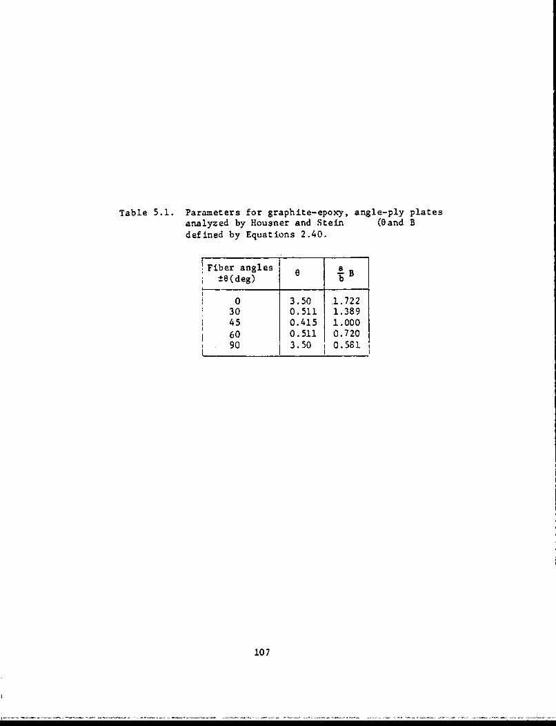
Table 5.1. Parameters for graphite-epoxy, angle-ply platesanalyzed by Housner and Stein (Gand Bdefined by Equations 2.40.
Fiber angles a-±e(deg) b
0 3.50 1.72230 0.511 1.38945 0.415 1.000
60 0.511 0.72090 3.50 0.581
107

b
a/b
4 1S - -1
1.1 -. - - .- -% N '1.25 -" __• N
3 - N _a/b
1// 02 2
x 5 gqual weight".,-- ,•aluminum plates
O Simply supportedo Clamped
AU edges Integer
2 -- - ClampedSimply supported
0 10 20 30 40 50 60 70 80 90* a
Figure 5.1. Compressive buckling parameters Nx for graphite-epoxy,angle-ply plates.
108

6a
+8
a/b/
4 /
N 3
2 Equal weight2 aluminilul Plates-
5 0 Simply suppu ried21 C: Clamped
22
5 5
5- Simply supported
0 10 20 30 40 50 60 70 80 90
Figure 5.2. Shear buckling parameters Ax for graphite-epoxy,angle-ply plates,
109

CAC
4) x
0
-4
110

i
80
60
-1r
0 /
1 2 $
?. Aspect ratio, a/b
'sFigure 5.4. Optimum fiber orientations for 5855, angle-ply platessubjected to shear loading.
ale
4 .)
qpE
!2
,ox
oo-
°-2
Asetrato /
Fiur 5.. Otmmfie retton1o SS ngepypae
sujce t ha laig

C Id
Q) (a
410-101
V4)~bb1
I %z GJO
I'-* (01 U)
ed UW)0 "'-1
u v?
I~Cr4400
coo CoColo
4- Zi
112

Housner and Stein [65] also computed and plotted interaction curves
for the buckling of alternating angle-ply plates subjected to simultaneous
axial compression and shear. Curves for various fiber orientation angles
(±O) for SSSS boundary conditions are depicted in Figure 5.5.
Fogg (32] presented an extensive set of numerical results for the
compression (uniaxial) and shear buckling of SSSS plates fabricated from
T300/5208 graphite-epoxy tape. Results were obtained using a finite
element plate analysis program [121]. Calculations were made for two
families of laminates: (4 5/ 0/- 4 5/ 0N)s and (4 5/ 90 /- 4 5 , 0 N)S, where s
indicates that the plate is symmetric, having twice the number of plies
shown in parentheses, and N indicates the number of 00 plies immediately
adjacent to the midplane on each side. Each ply was 0.005 in thick.
For example, the (4 5/ 0/- 4 5 / 0 )S laminate consists of eight plies,
arranged 450, 00, -450, 00, 00, -450, 00, 450, and a total thickness of
0.04 in and a bending stiffness in the x-direction of D11 - 53.795 lb-in.
A similar laminate having twice as many plies would have D -
53.795x(2) 3 - 430.36 lb-in. Laminate orientations, thicknesses and
bending stiffnesses of the various anisotropic plates studied are
summarized in Table 5.2.
Numerical results for the buckling stress resultants (N) in lb/in
for the plates described by Table 5.2 are presented in Table 5.3, along
with the complete plate dimensions. The width (b) was taken to be 20
times the thickness ( h) in each case. Lengths (a) were set to result
in one, two or three half-wave buckles in the mode shape. To evaluate
the effect of the D and D terms on the buckling loads, the buckling16 26
loads of orthotropic plates (D - D2 6 e 0) of infinite length were also16 2
computed. These plates are thus designated either OA" or "0* in the
second column of results, and the ratio of the anisotropic to the
orthotropic buckling loads (NA/NO) is also given.
Least squares curve fitting techniques were used to obtain the
following empirical formulas for NA/NO for the case of uniaxial loading
113
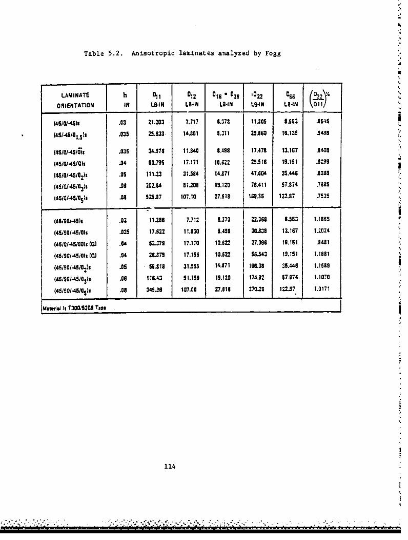
Table 5.2. Anisotropic laminates analyzed by Fogg
LAMINATE h 01 012 016 =026 '022 055 221 !i.
ORIENTATION IN LB-N LB-IN LB4N L84N LB4N \011/
(45/0145)1 .03 21.203 7.717 6.373 11.305 8.563 .8545
(451/48/OllS .035 U.633 14.801 5.311 20.860 18.135 .348'
145t0/-4510) .035 34.978 11.840 8.498 17.478 12.167 .8408
(4540/45/0)s .04 53.795 17.171 10.622 25.516 19.151 .3299
(4510/45t0z1s .05 111.23 31.584 14.871 47.804 35.446 .8088
(51401.45i03)1 .06 202.84 51.208 19.120 78.411 57.874 .7885
I4510/451051s .08 525.37 107.10 27.618 169.55 122.87 .7535
(W1901.45) .03 11.,8 7.712 6.373 22.368 8.553 1.1865
(4.r90/-45/0)s .035 17.622 11.830 8.488 38.838 13.167 1.21024
(4510/-45/90)s (CU .04 5-2379 17.170 10.622 27.096 19.151 .843,1
(45i90i-4Si01 10. .04 26-U73 17.156 10.622 55.543 19.151 1.1881
(45i301-4510 2s .05 58.818 31.555 14.871 106.08 35.448 1.1589
(45/80/-451038) .06 116.43 51.159 19.120 174.82 57.874 1.1070
(45180-46101)t .08 345.•6 107.00 27.618 37016 122.87 1.0171
Maiuil Is T30015201 Taoa
114

id r
0.. ps -W C
e4 4n
Cri CO U
-~ p..9fl al. 9!P ~ J40w0 cc.p~ Z -~nw @ 1
41.
(D0.S0 40 -W C* CA1 -
ZZ 40 -W -W g. p
aA in444 um a~~ u's ~ a ca, p4 C- On4~41
an w CD C0 40 Cq 4R 41!
4L IL C6 ES
cU Up U- mW@
CO.c. 40014 dc 4c0044 e--e
0.n
* 1.5

C"i r"e fl tl eSlA "
ca W %nto 4W a & .0 V
Wo . to
ZN
s 0
C C*
to - - tm m W W
NN"" ca wOt t 0 e4N e- <
.32 w am as as do a*
to' t
CCC i ~ N w w
________ ______________________________ 116_____

F3 -C" - n1 na
c " . e as...4.,
.,4 t4 ,, C • ft U3 , cn rlC4 em . . . f" .,- e,' em W- , en@ em C4 C
a! al a! di ac42 PsW34 -r40~ n-s 4'3334.440" 4 4." 44 4n199 r -W -W " Sr ,S 4p4 A Wi 'CaIn
,i..a
.3"2c Ps*434 -r43 44 43 es--e "- mf nc
on a~ &9 abn to 4.4 La. tA to c= 43c =1
CRC R I IR IR RN
go A19 C" 0"4343W1a C4 4.4 qS qs cc ccn1
4- ,,-4 C" I
0n- C 0 a. -6 ~4 I C6 0.ILe.4. 293N44 a444 Al cc cc x 2 c
m E 1 9N 1119 m P*~9 1
n2n ~ 04 43 43 = ..
C.3a 4 -.-a 3U3(
2 C431C9 0 - 0339. 4343C c 1 E4c 4.4IN 4c 0
me~ gN £ f 4.4.WP414
S iai
117 aaa

CIA
-V --- A me4 C- -II % ar mc
02 0 a* a. do
ab a qa qrq 0r a ko a
r4 ri - - C-4 4 " f
00 S 40
f4 ... faC i.0 w I i
4c ~P c < C C2 1C
Lna
,~ e 4aW118
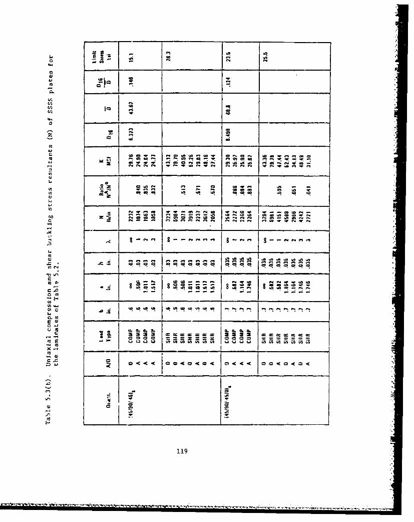
cni
0 q
to enm - r a4"4 W c * f
(p.
Im C, -n
r r4fo -a ni A -c "c
eo 04 La f- )C "44C 2 ' ý c n r
.0 Lei
f4 ri e c m dr uioa cidiC-4w wVNdi(% 10 I = i ai ci W -W
0 -
rd X
C~Lfl z 4 0 -K a cin - -
to NL' iU)
O 2
- I 'a 119

II
r, 41 4" .. .. 0-i .. C4
go4.4 C4 f 3f t M4- ai a M 4
to ( 0Mc - o Wu
4- cnfo r e oI
M CR w iR •R 4 Rv ý r:w 0
,,C-4 a M C# MWD C"4.4 C 4 444 C4 14 Nr o
IZ ° . . . . .. . .
0 ~ ~ 06 CL. 4. 9L I09 LC
La m u AC s 4C w w (A(A(AU
A-ii
000 00000c(z4c 0 4c0 0 4c@ 0 cCc
I -•
120
NO a. .. .. ......

InI
4q4
IN: IV "'I LF- 4 f4 m ft w I
94 q -4r " wr-W W-
W3 in
w La vs%-at n% Ac o ( ac AI at
-Ws e q-r emW4t q. ~ 4-a'e-P-~m 'aa- c "IN a~aO 4-
4* . . .N4 4*i 4!mi - I* - C4 Nw N n £ "
a Aa f40 0 a a 0
e cr0 a4 4 a * ~ * . ~ O
La4~4¶4. 4 aN IN121*~

to tfl-
PSU 4f
49 -1 ý Q R ot4
- 0 I C
-j5 1( Q4= Z
to C - 0 4 4 4
qr
a.122

only [32]:
N A fD 16) 9
NO 5.)585 for A=j (5.4a)
,'!D 6 2. 135
= for A=2 (5.4b)
D 16 2.117- 1 9 . 7 6 6 ;i for X=3 (5.4c)
where D• (D1 1 D32 ) 1/L+ (D2+2D6 6 ) (5.5)
When the data of Table 5.3 are compared against these curves, most of
the values fall within one percent of the curves, with the maximum error
being four percent.
Studying Equations 5.4 and 5.5, and Tables 5.2 and 5.3, effects of
the bending-twiating coupling coefficient D16 (and D2 6 ) in changing the
buckling loads from those of orthotropic analysis may be seen typically
as follows:
1. The buckling loads are always decreased.
2. In the case of uniaxial compression longer plates (larger X)always have larger decreases.
3. Shear buckling loads are more greatly decreased than those due
to uniaxial compression.
Mandell [34,35] conducted an experimental investigation of uni-
axial buckling loads for graphite-epoxy and boron-epoxy, angle-ply
plates. A description of the plates tested is given in Table 5.4.
Plate identification numbers given are those used in [34,35]. A ply
layup 4(±60) would indicate a stacking sequence with respect to the load
direction (600, -600, -600, 600), 5(+45) would describe the sequence
(450, -450, 450, -450, 450) and 20(30) means that 20 plies are all with
123

Table 5.4. Description of anisotropic plates tested by
Mandell
Plate Material % Fiber Layup of Dimensionsno. by volume plies (in)
203a Thornel-25 40,0 9(t45) lOx lOx 0.116203b o If "
208 Thornel-40 60.0 (0,45,45,45,0) 10 x 10 x 0.038401 Boron 48.2 20(-60) 11 x ii x O.ilo402 " " 20(±30) 14 x 1! x 0.110"403a " 57.0 20(±45) 11 x l1j x 0.110403b " "406 " 51.7 20(30) llx llx 0.106407 " 20(60) "408a " 58.6 20(45) 11 x 1' x 0.095408b ... 20(-45)
Table 5.5. Bending stiffnesses (lh.i) for Mandell's anisotropicplates
Plate I D D D D D D1 ,I 12 16 22 26 66
203 455 326 -100 455 -100 349208 10.7 6,77 -5.75 94.2 -5.75 8.50401 480 655 44.6 1943 145 666402 1943 655 145 480 44.6 666403 970 782 97.3 970 97.3 799406 1870 631 923 481 298 644407 481 631 298 1870 923 644408 839 671 551 839 551 686
1
124

I
Table 5. 6. Stretching stiffnesses (103 lb/in) for Mandell'sanisotropic plates
4
Plate A A A I A A A11 12 16 22 26 66
I203 405.4 290.1. -30.02 405.4 -30.02 310.4208 532.*3 136.8 -132.8 178.3 -132.8 151.2401 476 649 0 1926 0 661402 1296 649 0 476 0 661403 1141 921 0 1141 0 940406 1996 t673 986 513, 299 688
1
407 513 673 299 1996 986 688408j 1115 893 732 1115 732 912
125
A'
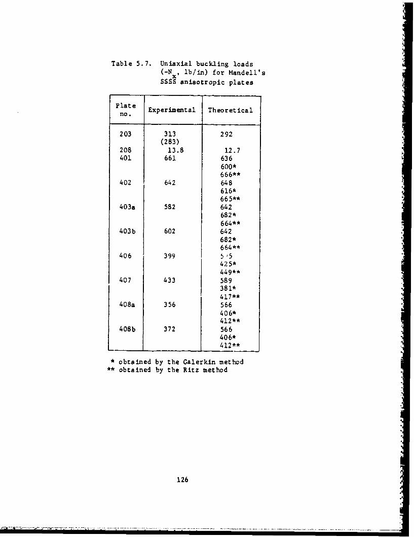
Table 5.7. Uniaxial buckling loads(-Nx, lb/in) for Mandell's
SSSS anisotropic plates
Plateno. Experimental Theoretical
203 313 292(283)
208 13.8 12.7401 661 636
600*666**
402 642 648616*665**
4 03a 582 642682*664**
403b 602 642682*664**
406 399 5,5425*449**
407 433 589381*417**
4 08a 356 566406*412**
408b 372 566406*412**
* obtained by the Galerkin method** obtained by the Ritz method
126

fibers oriented at 300 with respect to the loading axis. Bending
stiffnesses for the plates are given in Table 5.5. The anisotropic
character of the plates in bending is clearly seen (D and D are not16 26
zero). The stretching stiffnesses are listed in Table 5.6. Although
the plates are symmetrically laminated, and therefore the stretching
stiffnesses do not couple with the buckling problem, the latter table is
presented to show that some of the plates are orthotropic in stretching
(A16 and A26 are zero), even though they are anisotropic in bending.
More information on these tests is found in Section 2.1.
Table 5.7 lists the experimental buckling loads for the plates
described in Table 5.4. Also given are theoretical values obtained by
three methods, using the bending stiffness data found in Table 5.5. The
first method ignores the D16 and D26 terms, and uses Equation 2.9 for an
orthotropic plate. The second and third methods utilize Galerkin and
Ritz formulations, as applied by Chamis [411 and Ashton [42], re-
spectively. Plates 20:, 403 and 408 are each listed twice. The two
cases (denoted "a" and "b") identify uniaxial loadings in two perpen-
dicular directions. For these plates, different experimental results
were found, although the theoretical results are identical for each
loading direction. It is interesting to note, contrary to the results
of Fogg (32] presented earlier in Table 5.3, addition of D16 and D2 6
terms to the analysis does not necessarily decrease the theoretical
buckling loads shown in Table 5.7.
Chamis (43,44] used the Galerkin method to analyze the buckling of
858 anisotropic plates subjected to combinations of compression and
shear loading. Two sets of problems were treated. The first set
consisted of plates having the fibers all parallel, making an angle 0
with respect to the x-axis. The second set were angle-ply plates,
having alternating plies at +0 fiber angles. Specifically, the plates
were comprised of 20 plies, the top 10 being ±0, and the bottom 10 being
;e, to preserve symmetry. Bending stiffnesees for the first set are
127

displayed in Table 5.8, computed using the ply material properties
listed in Table 2.7. Critical buckling loads for various loading
conditions and sizes of plates for the first set of problems are given
in Table 5.9. Stiffnesses and buckling loads for the second set are set
forth in Table 5.10 and 5.11. Corresponding results for the same plates
having 0 - 0 and 900 were given previously in Table 2.9. Comparing
Tables 5.8 and 5.10, one observes that the only significant differences
between the bending stiffnesses of the two sets of plates is in the
bending-twisting coupling terms D16 and D . Additional discussion of16 26
the solution procedure may be found in Section 2.4.
Considerable interest has existed in the optimization of fiber
orientation to obtain the largest value of critical load. Some work in
this direction has already been seen in Figures 5.3 and 5.4. An
extensive study for SSSS plates subjected to uniaxial compression (ox
- constant, a y - txy - 0) was undertaken by Crouzet-Pascal [12d] using a
finite element method. Three types of laminates were considered, having
"severe, medium or mild" orthotropy with respect to the principal
material axes of the plate, which in turn are oriented at an angle 0
with respect to the sides of the plate. The three types are described
by the laminate material properties listed in Table 5.12, where L and T
are principal material axes. For 0 - 00, then EL - Ex, ET - Ey, etc.
The plate having severe orthotropy consisted of 50 graphite-epoxy plies,
all having parallel fibers. Medium orthotropy corresponds to 20 glass-
epoxy plies, with parallel fibers, Mild orthotropy stemmed from the
reorientation of the layers of the severe orthotropy case, with 14, 14,
14 and 8 layers oriented at 00, +450, -450 and 900, respec-'vely
relative to the principal material axis.
Optimum material axis orientation versus plate aspect ratio for
the laminate having medium orthotropy is shown in Figure 5.6. Results
obtained [122] are compared with those of Chao, Koh and Suri [123] for
128

Table 5.8. Bending stiffnesses (lb.in) for Chamis' parallel-fiber anisotropic plates
Fiberangle D 1 D12 D16 D22 D26 D66e(deg)
15 2143 172.9 531.4 148.5 44.4 205.330 1440 454.0 742.1 228.0 255.1 486.545 724.1 594.6 575.8 724.1 575.8 627.060 228.0 454.2 255.1 1440 742.1 486.575 148.5 172.9 44.4 2143 531.4 205.3
129

Table 5.9. Buckling loads Ncr(lb/in) for Chamis' SSSS parallel fiberanisotropic plates
Plate Loading condition Buckling load, Nrdimensions N N N -'
(in) x _ 'y e=15' e=3o* e=450 e=600 6=75 6N N Ncr cr cr
5.OxlO.0 -1 0 0 949 813 620 403 219"0 -1 0 847 1306 1506 1407 876
"-1 -1 0 623 648 495 322 175""- 0 1 838 661 456 315 193
"0 -1 1 645 718 635 518 446 I"-1 -1 1 494 510 374 249 159
" -0.001 0 1 1458* 1238* 980* 808* 667*
10.OxlO.O -1 0 0 328 417 425 344 213"0 -1 0 213 344 425 417 328
"-i -1 0 164 208 218 208 164"-1 0 1 233 223 205 197 164"0 -1 1 165 197 205 223 233
"-1 -1 1 136 146 145 146 136
"-0.001 0 1 418* 382* 391* 385* 412* ,
"-1 -0.75 0 187 236 225 237 178"-1 --0.50 0 218 276 262 277 188"-1. -0.25 0 262 331 312 322 200 I
"-1 0.25 0 436 552 488 353 221"-1 0.50 0 654 827 554 386 239
" -1 1.00 0 1223 970 696 465 280
"-1 -0.50 0.25 209 232 229 240 179
" -1 0.50 0.25 563 570 438 342 225"-1 -0.50 0.50 196 207 200 213 169"-1 0.50 0.50 469 431 348 294 209
20.OxlO.0 -1 0 0 219 351 377 327 212
"0 -1 0 55 101 155 203 237"-1 -1 0 44 81 124 162 156"-1 0 1 112 135 159 180 175
"0 -1 1 48 79 114 165 209
"-1 -1 1 40 66 94 128 123"-0.001 0 1 167* 204* 246* 306* 360*
4 0.0xi0.0 -1 0 0 216 336 417 392 268" 0 -1 0 22 45 91 157 210
"-1 -1 0 21 42 86 147 163"-1 0 1 90 126 183 238 239
"0 -1 1 22 42 85 149 210
"-1 -1 1 21 40 80 139 139
"-0.001 0 1 127* 168* 253* 371* 505*
* values lacking convergence
130

Table 5.10. Bending stiffnesses (lb.in) for Chamis' angle-ply plates
Fiberangle DII D12 D16 D22 D2 6 D6 6
±8(deg)
15 2141 172.7 79.6 148.5 6.7 205.130 1439 453.6 111.2 288.6 38.2 486.045 723.4 594.0 86.3 723.4 86.3 626.460 288.6 453.6 38.2 i 1439 111.2 486.075 148.4 172.7 6.7 2141 79.6 205.1
131

Table 5.11. Buckling loads N cr(lb/in) for Chamis' SSSS angle-ply plates
Plate Loading condition Buckling load, N
dimensions N N N(in) __a_ xy e-+15* 6=-±30' 6=-+45° e=_+60° 8=t75"
Nr cr crI
5.OxlO.0 -1 0 0 963 854 665 429 226" 0 -1 0 901 1622 2016 1716 904
"-1 -1 0 669 683 532 343 181"-1 0 1 905 798 621 401 213
"0 -1 1 786 1271 1402 1054 577"-1 -1 1 601 650 506 327 173"-0.001 0 1 2290 2823 2571 1772 995
10.Ox10.0 -1 0 0 340 450 505 428 226" 0 -1 0 226 428 505 450 340" -1 -1 0 170 225 252 225 170" -1 0 1 283 370 414 363 20]" 0 -1 1 201 363 414 370 283" -1 -. 1 159 210 235 210 159" -0.001 0 1 671 914 1038 914 671
"-1 -0.75 0 195 258 289 258 190" -1 -0.50 0 227 301 338 301 201
"-1 -0.25 0 273 361 405 361 213
"-1 0.25 0 454 602 675 458 241"-1 0.50 0 681 902 761 491 259"-1 1.00 0 1284 1140 888 573 302"-1 -0.50 0.25 225 299 334 298 199"-1 0.50 0.25 647 849 741 482 255"-1 -0.50 0.50 221 292 328 292 106"-1 0.50 0.50 579 755 702 464 249
20.OxlO.O -1 0 0 226 429 504 405 225" 0 -1 0 56 107 166 213 241" " -1 -1 0 45 86 133 171 167" -1 0 1 144 263 351 318 196" 0 -1 1 53 100 155 200 226" -1 -1 1 43 82 127 163 150
"-0.001 0 1 249 443 643 706 591
132

two values of a/b. For a/b a 1, both analyses gave the same result.
For a/b - 2.5 they differed by approximately two percent. The variationof critical stress with material axis orientation (0) is depicted in
Figure 5.7 for the two cases of a/b - 1 and 2.5 described above. There
a indicates the number of half-waves of the buckling mode in the loaddirection. Transverse to the load the mode shape has one half-wave.
The node lines of the mode shapes have been found to rotate with the
material axes, and remain approximately normal to the stiffer materialaxis over the whole range of orientation [42). The results of similarstudies 1122] for the plates having mild and severe orthotropy are seen
in Figures 5.8 through 5.10.
A number of other optimization studies have been made for SSSSanisotropic plates 128,34,68,101,124-135). Optimization under biaxialloading conditions was treated by Bert and Chen [125] and by Lukoshevichyus
(131]. Biaxial loading combined with shear was dealt with by Schmit and
Parshi [133].
The case of the infinitely long anisotropic plate simply supported
along its two edges (y = 0,b) and subjected to combined longitudinal
(ox), transverse (ay), shear (Txy) and inplane bending (see Equation
2.43) was analyzed by Wittrick 11203. Critical values of the parameter
KL are given in Table 5.13 as the parameters .J2 and Ks are varied, for
the case of no bending stress. The parameters are defined as follows:
-a hb2
2 - 2R K + R2[(I+R 2 2-R (5.6a)ZD22 3R23 s 15 2-
T hb2Ks -- Q•D 2 2 + 2f-2 (R 2 3+R• 3 -R1 3)
3 (.6b)
133

Table 5.12. Principal axis material properties of platesanalyzed by Crouzet-Pascal
Type of EXlO-6 Zx10-6 GLTx10-6 VLTplate (psi) (psi) (psi)
Severe orthotropy 18.5 1.6 0.65 0.25Medium orthotropy 7.8 2.6 1.25 0.25Mild orthotropy 7.64 5.87 3.00 0.409
134

gO.
'S.
e•,, 0 [122)
30'
Glbq
'S.q
a/
Figure 5.6. Optimum material axis orientation versus zspect ratiofor a uniaxially loaded SSSS plate (unidirectional,medium orthotropy laminate).
135

SA
"I o.4
b
52-
3o so 50 60
O0EG
d'b 2 I
tation corepndn to a/ -- ad2.inFgr
5. (uiietoa, eimotoroylmnt)
6136
x
6..%
SO0EG 6
Ie'b,, 2 •
Figure 5.7. Variation of critical stress with material axis orieil-tation, corresponding to a/b - 1 and 2.5 in Figure5.6 (unidirectiona1, medium orthotropy laminate).
136 .Ia

16.0
- 15.0
13.0 t0 10 20 30 40 so so 70 so
Figure 5.8. Variation of critical stress with material axis orien-.tation, a/b -2.5 (angle-ply, mild orthotropy laminate).
137

0
13.0
1 2.0
1..0
ao.o /,/ - - I
/ I
t!0I , , I I . ii .
0200 30 mO so 0 70 -o9
8 COE
Figure 5.9. Variation of Critical stress with material axis orien-tation, alb -2.5 (unid'rectional, severe orthotropylami nate ).
138
NINEL• . . .. , .. ;: • "7 ' ." . .- < - - -. -. - -. . -- - .. I-, . . . . - . .
--- .. • ••,--:--.-•-• -,,,I,+•A'.• . -" :"" • " . -

14.0 * 2
0 ,0
b
4•I _. I
o 3o o cQ
Figure 5.10. Variation of critical stress with material axis orien-tation, a/b 1 I (unidirectional, severe orthotropylaminate).
139

02 Q (!1 (5.6c)
where
D! .-1 2 -3/2 R2 3 ( - 1/2
E2 22)
L /D262 A2a h
2 22 2TrzD 22
with A being the longitudinal half-wavelength and o x and 0 y taken
positive in tension, as elsewhere in the present work. The infinite
strip having its principal material axis oriented at 450 with respect to
the simply supported sides, subjected to uniaxial compression or shear,
was also treated by Thielemann [136,137].
In addition to those references listed previously in this section,
many others are available which consider the buckling of 8SSS ani-
sotropic plates [14,26,45,101,138-149], most of them dealing with
uniaxial loading conditions only. Sarkisyan and Movsisyan [144]
demonstrated how the perturbation method may be used, whe:e, the zeroeth
ordeE perturbation ia the orthotropic plate. Therefore, for small D1 6
and D26, the first order perturbation will be an accurate representationof an anisotropic plate. Whitney [147,148] demonstrated the rapid
convergence of the series method for anisotropic problems. Ashton and
Waddoups [138] showed that the buckling load of a 1450 angle-ply plate
may either decreaso or increase when loaded in shear, depending upon
whether Txy is positive or negative, respectively.
5.2. SCSC
Ashton and Love [112] conducted a set of experimental tests on
140
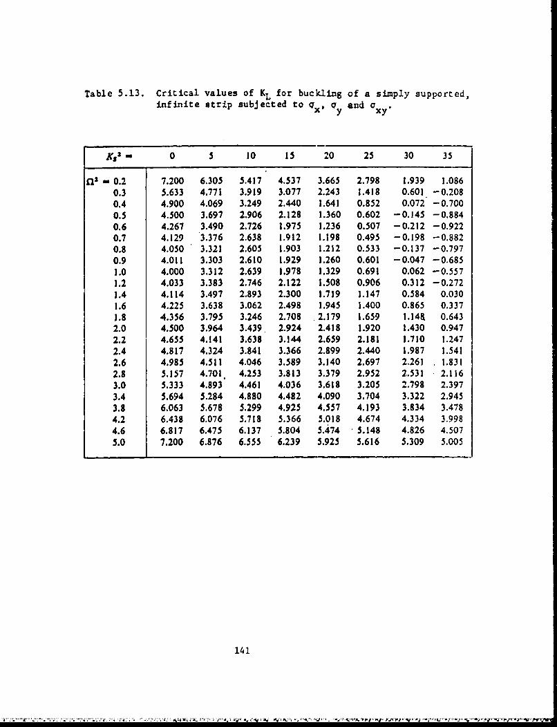
Table 5.13. Critical values of KL for buckling of a simply supported,infinite strip subjected to qx, oy and Oxy
SKS2 0 5 10 15 20 25 30 35
E22 - 0.2 7.200 6.305 5.417 4.537 3.665 2.798 1.939 1.0860.3 5.633 4.771 3.919 3.077 2.243 1.418 0.601 -0.2080.4 4.900 4.069 3.249 2.440 1.641 0.852 0.072 -0.7000.5 4.500 3.697 2.906 2.128 1.360 0.602 -0.145 -0.8840.6 4.267 3.490 2.726 1.975 1.236 0.507 -0.212 -0.9220.7 4.129 3.376 2.638 1.912 1.198 0.495 -0.198 -0.8820.8 4.050 3.321 2.605 1.903 1.212 0.533 -0.137 -0.7970.9 4.011 3.303 2.610 1.929 1.260 0.601 -0.047 -0.6851.0 4.000 3.312 2.639 1.978 1.329 0.691 0.062 -0.5571.2 4.033 3.383 2.746 2.122 1.508 0.906 0.312 -0.2721.4 4.114 3.497 2.893 2.300 1.719 1.147 0.584 0.0301.6 4.225 3.638 3.062 2.498 1.945 1.400 0.865 0.3371.8 4.356 3.795 3.246 2.708 2.179 1.659 i.14& 0.6432.0 4.500 3.964 3.439 2.924 2.418 1.920 1.430 0.9472.2 4.655 4.141 3.638 3.144 2.659 2.181 1.710 1.2472.4 4.817 4.324 3.841 3.366 2.899 2.440 1.987 1.5412.6 4.985 4.511 4.046 3.589 3.140 2.697 2.261 1.8312.8 5.157 4.701 4.253 3.813 3.379 2.952 2.531 2.1163.0 5.333 4.893 4.461 4.036 3.618 3.205 2.798 2.3973.4 5.694 5.284 4.880 4.482 4.090 3.704 3.322 2.945
3.8 6.063 5.678 5.299 4.925 4.557 4.193 3.834 3.4784.2 6.438 6.076 5.718 5.366 5.018 4.674 4.334 3.9984.6 6.817 6.475 6.137 5.804 5.474 5.148 4.826 4.5075.0 7.200 6.876 6.555 6.239 5.925 5.616 5.309 5.005
141

SCSC plates loaded uniaxially, where the clamped edges were loaded and
the simply supported edges were unloaded (gy a constant, ax - -xy 0).
A total of 20 boron-epoxy laminates were evaluated. Layers of epoxy-
bonded boron fibers (Narmco 5505 prepreged type) were combined in direc-
tions located with reference to a 00 axis of plate symmetry as indicated
in Table 5.14. Material properties of typical plies were: E, - 3lxlO6psi,
E2 2.7xl06psi, G 0.75xlO6pei, V - 0.28. Nineteen of the twenty2 12 12
plates were symmetrically laminated (Plate 2 was unsymmetric). Plates U1, 3, 4 and 20 had principal material axes aligned with the plate edges
(i.e., orthotropic), the others behaved as anisotropic plates. Plate 11
had 12 plies, plates 15 and 16 had 16 plies, and the others all had 20
plies. Thicknesses varied no more than two percent throughout the
plates. Plate dimensions were lOxlO inches within the loading frame,
except for plate 11, which measured lOx5 inches. Plate edges had layers
of Teflon tape attached to reduce undesirable, secondary inplane forces
due to friction, which was found to be very important -- without it, the
induced stress resultant Ny was as much as 50 percent of the applied
stress resultant, causing buckling loads to be reduced by one-fourth to
one-third. The presence of induced secondary stresses was observed by
strain gages.
Critical buckling loads were determined by the Southwell
method [40]. These are listed in Table 5.15 [112]. Two tests were
conducted for each plate. The first test had the zero degree material
reference axis aligned with the load. Then each plate (except number
11) was rotated 900 and the tests were repeated. Results from both sets
of tests are seen in Table 5.15. Further details about the testing
procedure and observations may be obtained from [1121.
Sandorff [150] and Baharlou [101] studied a set of SCSC plates
with uniaxial load applied to the clamped edges (ay - constant,ax 1 'xy - 0). The plates were made of graphite-epoxy, with individual
142

00 W0 0 00 0 00 0 00 0
0 0f 00 C0
+
W)t 0 00
+ + +
C13
IT 0LO)~0 0 enj.6
$4
.0 0% Ir Ln II 0 0 I
OLri dLUr0 0
oa +' I4 + +++ J~ '4~J4)
o) V)4 V'%? %I)-. C:) % C
+ + TMI
'T 044 w0o9 Zn )O na 0 4
440)4 >%PN r4> P4r444m tQ -:60.cd0Ln r-4s Ln44) r
+~ 0d00 0+cC1 1 1Cl ) , (nC
C4 W )COO +
.0 .1 06 WM

Table 5.15. Experimental uniaxial buckling loads (ib) forSCSC plates corresponding to Table 5.14.
1 Load orientationPlate
no. 00 900
1 11,300 9,6002 5,400 5,6103 9,500 9,0004 7,400 7,2005 12,400 4,3506 5,600 6,1007 4,650 5,6008 8,600 8,4009 9,900 9,600
10 8,950 5,20011 3,650 -
12 14,700 7,55013 12,700 7,60014 12,650 7,75015 6,100 5,10016 5,400 4,80017 14,200 5,40018 13,200 5,90019 7,700 4,76020 13,700 4,200
144

Table 5.16. Unixial buckling stress resultants -NY (lb/in) forSCSC anisotropic plates (y - constant, x = T xy = 0).
Dimensions Experimental Theoretical resultsa x b results Sandorff Baharlou(in) [150] [150] [lO13
45303.003x9.625 4290 5185 5070
59102.503x9.625 5740 7249 7004
8140 1 6
2.003x9.625 8360 10,760 10,460
145
•'_ . ."-, - - • "• " "' ",,• " . -•-• -'-- •-•-- t. •° ?•-• •' -•-"• ' ",• •• • ' " '

22
6.4
plies having the following properties: E• - 19.0xlO5psi, E2 l 15x10 psi,
G - 0.8OxlO6psi, v - 0.30. The laminate orientation was (0/45/0/0/-12
45/0) 2S. The plates all had the same length in the loaded direction
(b = 9.625 in) and the same thickness (h = 0.1232 in). Three plate
widths were considered (a - 3.003, 2.503, 2.003 in). Buckling stress
resultants (lb/in) for the three plates are given in Table 5.16. It is
seen that as the width of the plate (a) is decreased from 3.003 in to
2.003 in, the difference between the two sets of theoretical results and
the experimental data becomes quite significant.
Several other publications dealing with the buckling of SCSC
anisotropic plates have appeared [26,151-153].
5.3. SFSF
In Table 5.17 are listed the experimental buckling loads obtained
by Mandell [34,35] for SFSP anisotropic plates having the simply sup-
ported edges subjected to uniaxial loading. The plates are those
described previously in Section 5.1 (Tables 5.4-5.6). Theoretical
results in all cases were calculated on the assumption that the plate
bends as a simply supported beam having no transverse curvature or twist
(see description of analysis in Section 3.6). Theoretical results
obtained by the Ritz method developed by Ashton 142] are also given for
several of the plates in Table 5.17.
5.4. CCCC
Ashton [42] investigated the effect of varying 0 upon the uniaxial
(cx constant, uy = Txy a 0) buckling loads of parallel fiber composite
plates, as the angle (0) between the principal material axes and the
plate edges is varied. The Ritz method was used, with assumed displace-
ments taken as the product of vibrating beam functions. The material
146
• ~ ~ ~ ~~~~~~~ --. . ÷ *.. ... ..

Table 5.17, Uniaxial buckling ioads(-N , lb/in) for Mand-ll's
xSFSF aatsotropic plates
Plate
Exper imental The2oreticalno.
203a 33.8 44.9
203b 34.7 44.9
208 8.27 9.30
401 30.3 37.83,.3
402 137 161150*1:
141-3a 53 70. 660 .8**
403b 45 170.6
160.8**406 89 150
407 30.1 35.130.0**
4 0 8 a 41.6 79.6
408b3'.?51.8"**408b 34.2 70.65!.8*
** obtained by the Ritz method
14"/L 'U ,:. . .- - - - .- - :;: .: . .• • •

properties taken in the direction of principal axes were: EL/ET = 10,
GLT/ET = 0.25, vLT = 0.3. Numerical results for the nondimensional
buckling parameter -(7xhb 2/D• are shown in Table 5.18 for a/b = 1 and 2,
and for a variation of e between zero and ninety degrees. Results are
also given for an "orthotropic solution" for a/b - 1, wherein the Di 6
and D bending stiffnessea are omitted. The results for the square25
plate are also plotted in Figure 5.11. It is seen that neglect of the
D and D terms yields results which are considerably too high for e16 26in the vicinity of 450. The orthotropic analysis also corresponds to an
angle-ply plate having an infinite number of plies alternating at +Q,and practical laminates will yield results which fall between the two
curves of Figure 5.11. The node lines (lines of zero displacement) for
the critical mode shapes are shown in Figure 5.12. For orthotropic
plates, these lines are parallel to (or nearly parallel to) the edges,
but for anisotropic plates they are not.
Experimental results for the buckling of uniaxially loaded CCCC
plates were obtained by Ashton and Love [112]. These are given in Table
5.19. For information concerning the plates tested, see Table 5.14 and
Section 5.1.
Uniaxial and shear buckling parameters Nx and Nxy for aogle-piy,
graphite-apoxy plates having CCCC edges, as obtained by Housner and
Stein [65] were presented in Figures 5.1 and 5.2, respectively. Optimum
fiber orientations for such plates and loadings may be seen in Figures
5.13 and 5.14, which may be compared with similar curves for S555 plates
which appeared as Figures 5.3 and 5.4. Interaction curves for buckling
due to simultaneous axial com lion and shear are seen in Figure 5.15.
Nx and Nxy are defined by Equations 5.1 and 5.2, respectively.
The buckling of CCCC anisotropic plates subjected to uniaxial
compressive loads was also studied by Ashton and Waddoups [ 138J, using
148
:14

Table 5.18. Critical buckling loads (-Oxhb 2 /Dq4 ) for parallel-fiberCCCC anisotropic plates.
Principal material axis orientation, e (degrees)A
b 0 15 26.6 30 45 60 75 90
1 45.20 39.47 - 29.94 25.35 23.69 21.39 19.6545.20* 44.72* - 43.51* 42.26* 35.37* 24.16* 19.65*
2 25.53 25.19 22.00 - 20.08 18.50 17.75 17.35
* Values from orthotropic analysis (setting D1 6 = D2 6 0).
149C °1

Table 5.19. Experimental uniaxial buckling loads (ib) forCCCC plates corresponding to Table 5.14. ¾
Load orientationPlate
no. 00 900
1 15,500 15,2002 6,150 6,5603 13,900 12,2004 10,300 10,2005 12,000 4,9006 6,840 7,1507 5,800 6,1008 10,700 10,1009 12,100 11,700
10 9,800 8,20011 4,550 -12 17,600 10,60013 13,600 9,50014 13,900 9,80015 6,950 6,25016 6,850 6,60017 15,400 6,70018 15,.00 7,35019 8,700 6,50020 14,900 5,880
150
4.4

45
40
15 Ofthotropic
-Or.hh• 2 0 -Aey
D #0
20
10
IS10
5i
0 to 20 30 40 50 60 70 80 909
Figure 5.11. Comparison of anisotropic and Orthotropic solutions foruniaxial buckling of a parallel-fiber CCCC plate.
151

S= 00 e= 150 e- 300 e- 450
_60' 0- 750 0= 9go1.=
em 0 0- 150 e= 26.60
45 0 9 =600 0- 750
KI
e- 90
Figure 5.12. Node lines for the buckled anisotropic CCCC plates
corresponding to Table 5.18.
152
;I' .- -..---- - .-- - .•- .- •-.-- . •- . - - -: . • . .•• : - " . • - .. --" -r " '' " " ' " - " i- ' • i ' " ' 1 " .. .I . . . . .

SxCO
0
-41
I 0
I Eu
k '4 ,
--44EL0 u0 0)
-4 8
C4C
A01jaa uwl'
153I

4.40
0
0
0-
0
- #0
I4F-
Ln
154,

z
41
I fn00
EUu
42 z
EU 0L.44
OAj
L4-0
nu:0
-40
C-1
155.'

the Ritz method with beam functions, and by Green and Hearmon [26] and
Whitney [154,155], using a series (or superposition) method with
trigonometric functions. Fraser and Miller [156,157] analyzed these
problems for uniaxial compression and shear loading by means of the Ritz
method with trigonometric functions and Lagrange multipliers.
The case of the infinitely long anisotropic plate clamped along
its two edges (y = 0,b) and subjected to combined longitudinal (ax),
transverse (ay). shear (Txy) and inplane bending (see Equation 2.43) was
analyzed by Wittrick [120]. Critical values of the parameter KL are
given in Table 5.20 as the parameters S12 and Ks2 are varied, for the case
of no bending stress. The parameters are defined in Equations 5.6. The
infinite strip having its principal material axis oriented at 450 with
respect to the clamped sides, subjected to uniaxial compression or
shear, was also treated by Thielemann [136,137].
5.5. ELASTIC EDGE CONSTRAINTS
Symmetrically laminated angle-ply plates having all their edges
elastically restrained against rotation were analyzed by Housner andA
Stein [65]. Uniaxial compression and shear buckling parameters Nx and
Ny, as defined by Equations 5.1 and 5.2 are plotted in Figures 5.16
through 5.2i, respectively. The rotational spring constant kr used inthe abscissas relates the rotational moment to the change in slope at
each edge by
S=kn r Tn (5.7)
where n is the direction of the normal to the edge. The springs are
uniformly distributed along all four edges. The other edge condition is
w = 0. Thus, kr 0 and correspond to SSSS and CCCC plates, respec-
tively.
156

Table 5.20. Critical values of KL for buckling of a clamped, infinitestrip with KB=O.
Ks2 0 I0 20 30 40 50 60 70 80 90
0.2 28.381 27.103 25.832 24.567 23.309 22.058 20.812 19.573 18.340 17.1130.3 19.914 18.666 17.427 16.198 14.978 13.766 12.563 11.367 10.180 9.0000.4 15.728 14.509 13.302 12.106 10.920 9.745 8.579 7.423 6.276 5.1380.5 13.256 12.065 10.887 9.721 8.568 7.426 6.295 5.175 4.064 2.9640.6 11.641 10.476 9.325 8.189 7.065 5.954 4.855 3.768 2.691 1.6240.7 10.514 9.375 8.251 7.141 6.046 4.964 3.894 2.837 1.790 0.7540.8 9.694 8.579 7.479 6.396 5.327 4.272 3.230 2.200 1.181 0.1740.9 9.078 7.985 6.910 5.851 4.801 3.777 2.760 1.756 0.764 -0.2171.0 8.604 7.534 6.482 5.445 4.425 3.419 2.426 1.446 0.478 -0.4791.2 7.943 6.915 5.904 4.911 3.934 2.971 2.022 1.086 (1.162 -0.7511.4 7.527 6.537 5.565 4.611 3.673 2.749 1.839 0.942 0.057 -0.8171.6 7.263 6.309 5.374 4.455 3.552 2.664 1.789 0.927 0.077 -0.7631.8 7.102 6.181 5.279 4.393 3.523 2.667 1.824 0.994 0.175 -0.6342.0 7.012 6.123 5.251 4.396 3.556 2.729 1.916 1.114 0.324 -0.4562.2 6.975 6.114 5.271 4.444 3.632 2.833 2.046 1.271 0.507 -0.24"2.4 6.976 6.143 5.326 4.526 3.739 2.965 2.204 1.453 0.713 -0.017
2.6 7.007 6.200 5.409 4.632 3.870 3.120 2.381 1.654 0.936 0.2282.8 7.062 6.279 5.511 4.758 4.018 3.290 2.573 1.867 1.170 0.4823.0 7.136 6.376 5.630 4.899 4.180 3.472 2.776 2.089 1.412 0.7433.4 7.328 6.609 5.904 5.212 4.531 3.862 3.202 2.552 1.910 1.2763.8 7.562 6.881 6.212 5.556 4.910 4.273 3.647 3.028 2.418 1.8154.2 7.827 7.180 6.544 5.919 5.304 4.698 4.101 3.511 2.929 2.3544.6 8.115 7.498 6.892 6.296 5.709 5.130 4.560 3,996 3.440 2.8895.0 8.420 7.831 7.252 6.682 6.121 5.567 5.021 4.481 3.947 3.420
157
ý.N

0
~~1.4C~U)
E -4
D,
'-4
U r
-1 (a
0(9)
bb ri U
En40d)
~00
44
158

00.
~~4- '''- ~
Ix1:
-. CuHb r) oniV Uln1
bzJ AiE 04 0
JIG)
-4 S..tv U-0.-
Ln
~~DOJ
ZI
159n".

0.
'44
--
0.
C> Ed
en CD E3
co0 0 (AC.) o(~ o
(Auco
44 (A -L
uLfin- .4
L, .>ClEU.-i
Zf-..
160U

'144J
0
C.)1
0
44
14
E 4
Et
-C r0.-4>
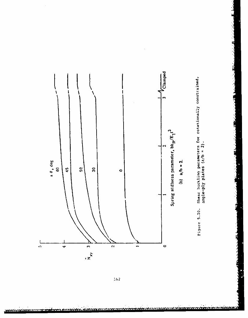
0 "0
0
4) oi
a -V
A04
41ý
,62,
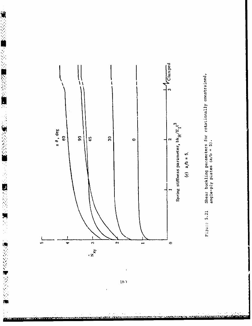
Sc
'U40)0
aa."ui tn
CI
$4
to
-~f 0)N.I.
A-t-
1611
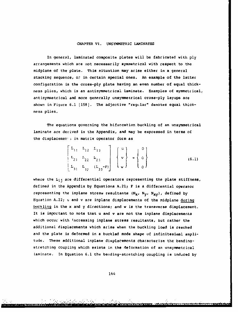
CHAPTER VI. UNGYMMETRIC LAMINATES
In general, laminated composite plates will be fabricated with ply
arrangements which are not necessarily symnmetrical with respect to the
midplane of the plate. This situation may arise either in a general
stacking sequence, or in certain special ones. An example of the latter
configuration is the cross-ply plate having an even number of equal thick-
ness plies, which is an antisymmetrical laminate. Examples of symmetrical,
antisynmietrical and more generally unsymmetrical cross-ply layups are
shown in Figure 6.1 [158]. The adjective "regular" denotes equal thick-
ness plies.
The equations governing the bifurcation buckling of an unsymmetrical
laminate are derived in the Appendix, and may be expressed in terms of
the displacemen' in matrix operator form as
L11 L1 2 L13 0
21 22 23 (6.1)L 3 L (L -F3 32 33
where the Lij are differential operators representing the plate stiffness,
defined in the Appendix by Equations A.21; F is a differential operator
representing the inplane stress resultants (Nx, Ny# Nxy), defined by
Equation A.22; u and v are inplane displacements of the midplane during
buckling in the x and y directions; and w is the transverse displacement.
It is important to note tnat u and v are not the inplane displacements
which occur with 4.ncreasing inplane stress resultants, but rather the
additional displacements which arise when the buckling load is reached
and the plate is deformed in a buckled mode shape of infinitesimal ampli-
tude. These additional inplane displacements characterize the bending-
stretching coupling which exists in the deformation of an unsymmetrical
Lamir.ate. In Equation 6.1 the bending-atretching coupling is induced by
164
- , . . ' • o"./ . ., .. . . . . ..,- - -
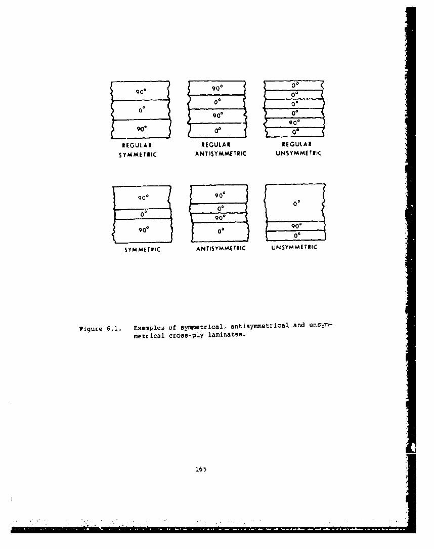
908go0
00
900:
REGULAR REGULAR REGULAR
S Y M METRIC ANTISYMIAETRIC UNSYMMETRIC
g0o 9006
0
90 00 00
SYMMETRIC ANTISYMM.ETRIC UNSYMMET12C
Figure 621. Examplej of symmietrical, antisymmetrical. and unsym-
metrical cross-ply laminates.
165

the operators L (=L ) and L3(-L2), which vanish only when the Bij13 31 23 32
bending-stretching stiffness coefficients (see Equation A.8) are all
zero. Then the plate buckling problem reduces to (L -F)w = 0, which is33
Equation 5.1 previously given for the anisotropic plate.
Equations 6.1 are an eighth order set of differential tions
which closely resemble the form of shell buckling equatio --h are
also of eighth order. (Indeed, the coupling between bending and stretch-
ing is what links together the two sets of fourth order equations which
would otherwise exist for a shell.) Since the equations are of eighth
order, four boundary conditions must be specified along each edge to
define the problem physically, and to generate a proper mathematical
eigenvalue problem.
The first satisfactory theory incorporating bending-stretching
effects into the deformations of laminated plates was developed by Reissner
and Stavsky 120,159]. This was done for the special case of an antisym-
mecrical, angle-ply plate, for which B B B B 0, which11 12 22 66
leaves B and B terms to cause the coupling. Governing equations for16 26
the buckling equilibrium position were expressed in terms of w and an
Airy stress function (f). Transverse equilibriun and inplane compati-
bility conditions were then used to generate an eighth order set of
equations equivalent to those of Equations A.32 and A.33.
Existence of the bending-stretching coupling in unsymmetrical
laminates was questioned (c.f., [159,160]) at the time of the
development of the new theory more than two decades ago. But, since
then, the effects have been demonstrated and quantified, both
theoretically and experimentally. The primary effect is to decrease the
stiffntess of a platel therefore, in the case of buckling, critical loads
-. d are reduced. As it will be subsequently seen, the effect is strongest
When. on~ly~' --mall.~ num!cr of pl.e1 is .ied, 611d deCLeaues as the number
increases.
166

-A.'
An approximate theory was suggested by Chamis 143] and Ashton [162]
for simplifying problems involving unsymmetrical laminates. It replaces
the eighth order set of Equations 6.1 by that of anisotropic plate theory,
Equation 5.1, where the bending stiffness coefficients Dij are replaced
by the "reduced bending stiffness" coefficients Df as given by the last
of Equations A.31. The boundary conditions are also reduced in numberfrom four to two, and the resulting solutions are independent of the
degree of inplane constraint. Comparisons of results obtained using the
"reduced stiffness" versus ones using the complete stiffness matrix show
"*' varying degrees of agreement [14,34,162-164] indicating that the approxi-mate theory is not accurate for all problems.
6.1. SSSS
For an unsymmetrically laminated plate, the meaning of a "simply
supported" edge is not clear. Assuming that, as in classical plate theory,
the edge must have zero transverse displacement and bending moment, there
remain yet four possible combinations of "simple" (i.e., not elasticallyrestrained) boundary conditions, depending upon the inplane constraints,
viz.
Sl : w = Mn = un = ut - 0
S2 w = Mn = Nn = ut 0 (6.2)
S3 w = Mn = un - Nnt - 0
S4 w = Mn = Nn = Nnt = 0
where n and t are used to designate directions normal and tangent to a
boundary, respectively. The bending moment (Mn), normal stress (Nn) and
shear stress (Nnt) resultants at edges x = constant or y , constant are
related to the displacement components by Equations A.38.
Two closed form, exact solutions are available for unsymunetLiCally
laminated plates subjected to uniform, biaxial stresses (ax constant.
167

G y constant, Txy - 0) [165,1661. One is for cross-ply plates having
S2 boundary conditions along all edges; the other is for angle-ply plates
having S3 edges.
For unsymmetrical cross-ply laminates, A1 6 - A2 6 a B16 - B26
D = D = 0 (antisymmetrical lamination simplifies the problem further,16 26
with A l=A2 2 , DII=D2 2 , B1 1 -B 2 2 , and B.=B 6 6=0). For plates of this
type having S2 conditions at x = 0,a and y = 0,b the exact solution takes
the form
= A cos MXsina b
SB sin MITX n-y
a b (6.3)
w = C sin MIX sin nTY
a b
with mn = 1,2,... The similarity of unsymmetrically laminated plate
equations and shell equations remarked upon earlier in this chapter is
again seen in Equations 6.3, for these are the displacement functions
yielding exact solutions for either (a) shallow shells of arbitrary (but
uniform) curvature and rectangular planform, with shear diaphragm support
conditions along all four edges (cf. [1671), or (b) closed circular cylln-
drical shells having shear diaphragm supports on the ends (cf. [1681,
p. 43). Substituting Equations 6.3 into Equation 6.1 yields
I.-
C 1 CC2 B , (6.4)C C3 3+(NxU2 +N y)ji c.
where
168

CI1 =A A 1a2 + A6 B2
= 82 ÷ 662
C A + A 222 22 66
C = Dl a4 + 2(D +2D )C12ý2 + D,,6'33 12 66
C1 2 = C2 1 (A 1 2 +A6 6 ) CL (6.r)
C = B 3 + (B +2B13 31 11 12 66
C23 = C32 (B I+2B 66) 2ý + B2..3
C, = - , = -a b
For a nontrivial solution, the determinant of the coefficient matrix of
Equation 6.4 must be set equal to zero, yielding the solution for buckling
stresses (Nx and Ny are positive in tension):
2C 1 2C 1 3 C 2 3 -C 1 1 C Z-C 2 2 C1
-N c - N 62 = C + (6.6)
It is seen that for a symmetrical laminate (Bij - 0), the right-hand-
side of Equation 6.6 reduces to C 3 3, and the equation is the same as
Equation 2.22 for the biaxially loaded, orthotropic plate having SSSS
edge conditions. For parametric studies, it may be desirable to recast
Equation 6.6 in terms of nondimensional parameters, as was Aone in changing
Equation 2.22 to 2.24. Once the eigenvalues (nondimensional buckling
parameters) are found from Equation 6.6, the eigenfunctions (buckled
mode shapes) are found in the usual manner for an #.igenvalue problem)
that is, an Pigenvalue is subt :ituted back into Equation 6.4, and the
169
I

eigenvector (A/C, B/C) which determines the eigenfunction is obtained by
solving any two of the three linear equations represented by Equation
6.4.
Jones [158] obtained numerical results for antisymmetrical and
unsymmetrical cross-ply laminates having S2 edge conditions, subjected
to uniaxial loads. Figure 6.2 shows the variation of Nxb 2 /u 2 D with22
a/b for representative graphite/epoxy plates (E /E2 = 40, G 2/E2 = 0.5,
= 0.25) having 2, 4, 6 and an infinite number of layers. The results
for an -ntisymmetrical laminate become the same as those for an orthotro-
pic plate as the number of layers goes to infinity (for Bil, the only
remaining bending-stretching stiffness coefficient, then goes to zero).
Figure 6.2 shows that for a/b - 1, neglect (f the Bij for a two-layer
plate will result in an orthotropic solution for the buckling load which
is about three times the correct value. As the number of layers increases,
the antisymmetrical solution rapidly approaches the orthotropic solution,
indicating a rapid decrease in Bil. For four and six layers, the ortho-
tropic solution for a/b a 1 is in error by 19 and 8 percents, respectively
11581. It is interesting to note in Figure 6.2 that the values of a/b
where the minimum buckling loads occur, are unchanged as the number of
layers changes. The same may be said for the locations of the cusps,
where the buckled mode shape changes from m to m + 1 half-waves. The
values of Nxb 2 /n 2 D22 for a/b - 1 are 0.7481, 1.7783, 1.9691 and 2.1218
for 2, 4, 6 and . layers, respectively. Identically the same values
occur for a/b = 2 and 3.
Figure 6.3 [158] shows the variation In uniaxial buckling load
with E I/E, for plates having G1 2 /E 2 - 0.5, ")12 ý 0.25 and a/b 1 1. The
loading parameter is plotted in the normalized form Nx/No, where No is
t!.e critical load for the orthotropic plate. These results may be used
to demonstrate, for example, that the orthotropic solution for a two-
lay-r, antisymmetrically laminated square plate is approximately 75 percent
too hign. However, for six layers it is only 5 percent too high I1581.
170

30
-OI1HOTIOPIC SOLUTION Ia,, 01
25
-Nxb 2
T,2.D22 20 I015
NUMBES
OFLAYIERS
,:40 [, -2• • 2SI101
0 p I0 S 10 1 5 20 25 30
PLATE AS?•CT IATIO. 9/b
Figure 6.2. Comparison of antisymmetrical and orthotropic solutionswith varying a/b for uniaxially loaded, cross-plyplates having 52 edge conditions.
M.
1/1

I6 4
NUAA f I
OF-N, LAYERIS
4 --
Noo '2
0 J-li
0 10 20 30 40 50E,
MOOULUS RATIO.
Figure 6.3. Comparison of antisynunetrical and orthotropic solutionswith varying E1 /E 2 for uniaxially loaded, cross-plyplates having S2 edge conditions (a/b - 1).
172

Results were also obtained by Jones 11581 for an unsymmetrically
laminated cross-ply plate having S2 edge conditions for the case of a
laminate having the fibers in the second layer from the bottom oriented
900 and the fibers in all other layers oriented at 00 to the direction
of loading (x-axis). Thus, for a constant thickness laminate, the 900
layer becomes thinner and moves to the bottom of th_ laminate as the
number of layers increases (see Figure 6.4). The buckling parameter
-Nxb 2/E 2h 3 versus number of layers is plotted in Figures 6.5 and 6.6 for
graphite/epoxy and boron/epoxy plates, respectively. In both cases,
a/b - 2. In both figures, one comparison is made with the buckling load
for a parallel-fiber laminate having 00 fiber orientation, and another
is with an orthotropic solution (setting all Bij - 0). The discon-
tinuity observed for the latter curve in Figure 6.6 is due to a mode
shape change. In the case of three layers, the laminate is symmetrical,
and the exact solution coincides with the orthotropic solution. It is
particularly important to note that in both Figures 9 and 10, but
especially in the former case where 2 /E = 40, the exact solution
approaches the orthotropic solution with increasing number of layers
much more slowly than was seen previously for the antisymmetrical
laminates (Figures 6.1 and 6.2). Significant differences are seen to
exist even with 40 layers.
For antisymmetrical angle-ply laminates, A]6 0 A26 0 D16 0 D26
BI1 = B22 - B12 - 0 (cf. [16], pp. 169-170). For plates of this type
having S3 boundary conditions (see Equations 6.2) at x - 0,a and y - 0,b
and biaxial loading the exact solution takes the form 1165,166]
U A s51 27X,a
":QoS -- sin --- (6.7)a
snC S -- 51a b
173

00 000 00003 LAYERS 4 LAYERS 5 LAYERS
II
00000
6 LAYEIS 12 LAYERS * LAYERS
3
Fiqure 6.4. Unsymmetrical laynnate having one 900 layer locatedsecond from the bottom.
174
m!

30 I
.~~~ ~~Ar' OA~O
20
100
0 400
yjgre .5. cotparsonof ~syuiutrialfort~trpicand parallel
fibe n s O fti ns for graphite/ "~' cros.-P
1 y Plate
having9 S2 edges and teLVP
h~li i~e64
175

I~ 00
10 ,
II
--N
2b
00 20 40 60 s0 100
NUMBER Of LAYIERS
Figure '.6. Comparison of unsymmetrical, orthotropic and parallel-fiber solutions for boron/epoxy, cross-ply plateshaving S2 edges and the layups shown in FIcure 6.4.
176
U

Substituting Equations 6.7 into 6.1 again yields a set of algebraic equa-
tions which may be written in the matrix form of Equation 6.4, where now
C11 = -(A 1 012 +A66 82)
C22 m-(A 228 2 +A 66a2)
C33 = DIa4 + 2(D 2+2D 66)282 + D 2284 (6.8)
C12 = 21 -(AI2+A66)ae
C13 = 31 3B16 2ý + B26B3
C ~C B a 3 +3B CL6223 B2 16 26
= mTr nWra--- , 8=----a b
The critical buckling stress resultants are given by Equ&tion 6.6, where
now the Cij are defined by Equations 6.8. It was also shown [165,166,169]
that the buckling stress may be written as
-axh 172 (D m4 + 2(D2+2D6)m 2 n2 R2 ý D nI.R4X ,. 11 12 66 22 I
a2 [m2 +n2 )2Ja X (6.9)
- -•[J m(B rm2 +3B n2 R2 ) + J n2 R2 (38 1n2+B2 n2 R2 )]}J6 16 26 5 16 26
where
177
• . . . .. . . • . . . . . . . . ; . .law

J = (A m2 +A 66n 2 R2 ) (B 6m2 +3B 6n 2 R2)
(A +A ) (3B m2 +B n 2 R2 )n 2 R2
12 66 16 26
= (A m2 +A2n 2 R 2 ) (3B m2 +B n 2 R2 )
J5 (A66 m A22 n16 26R
- (A 2+A 66) (B 16m 2 +3B 26n 2 R2)m2
12 66 16 26
J 6 = ( 1 m2 +A6 n2 R2 ) (A 6m2 +A 2n 2 R2 )
-6 (A212+A 66 n2R
with R = a/b.
Jones, Morgan and Whitney [170] obtained numerical results for
antisyiuetrical angle-ply laminates using the above exact solution. The
buckling parameter -Nxb 2/E 2h 2 is plotted versus lamination angle (e) for
uniaxial and hydrostatic (Nx = - constant, Nxy - 0) compression in
Figures 6.7 and 6.8, respectively, for the case of a square plate, with
EI/E 2 = 40, G12/E 2 - 0.5 and V12 - 0.25 (corresponding to graphite/epoxymaterial with E, = 30xl06psi, E2 = 0.75xlO6 psi, G12 w 0.375x10 6 psi, v * 0.25).
Corresponding data are also given in Tables 6.1 and 6.2. Comparisons
are made for plates having 2, 4, 6 and infinite layers, the last case
corresponding to an orthotropic plate (Bij all zero). It is seen for
both types of loadings that the optimum lamination angle is 0 a 450, and
the error in using orthotropic analysis for the antisymuetrically laminated
plate is very large for 0 450, being 211 percent for both types of
loading. Chen and Bert [1691 and Hiayashi (126,127] also determined the
optimum angle for maximum uniaxial buckling load to be 0 - 450 for a
series of antisymmetrically laminated angle-ply plates with S3 boundary
conditions.
Consider next the arn..... ymt Atrically laminated angle-ply plate having
S4 edge conditions (see Equation 6.2) all around. This problem was solved
178
...

Cso
ORTHOTROPIC SOL'JTION -N,1B16 816 01
o0 6
• ~L_
b
- 40 NUMBEROF
LAYERS
S:40 e :.5 t/, 1: .2 520 2
00 15 30 45 60 75 90
LAMINATION ANGLE e
Figure 6.7. Comparison of antisyimmetrical and orthotropic solutionswith varying lamination angle for uniaxially loaded,
angle-ply plates having S3 edge conditions (a/b 1 1).
179
p • A

40
ORTHOTROPIC SOL.UTION•
__" (B0 26 : 0)
30
2
Nb2 .
12h2 20
Z~Nj LB EROF
LAYER~S
10 O2
40 :.S': .25
0 I
0 15 30 4s
LAMINATION ANGLE
Figure 6.8. Comparions of antisymmetrical and orthotropic solutionswith varying lamination angle for biaxially loaded,angle-ply plates having S3 edge conditions (a/b- 1).
180

Table 6.1. Uniaxial buckling loads for square antisymmetricallylaminated graphite/epoxy plates (corresponding to Fig. 6.7).
-Nxb 2/E 2h3
e :Number of Layers
2 4 6 -(Orthotropic)
0 35.831 35.831 35.831 35.83115 21.734 38.253 41.313 43.76030 20.441 49.824 55.265 59.61945 21.709 56.088 62.455 67.54860 19.392(m=2) 45.434(m-2) 50.257(m-2) 54 .115(m= 2)75 12.915(m-2) 22.0 75(m=2) 23.772(m-2) 25.129(m=2)90 13.132(m=3) 13..32(m=3) 13.132(m-3) 13.132(m-3)
Table 6.2. Biaxial buckling loads for square antisymmetrically laminated
graphite/epoxy plates (corresponding to Fig. 6.8).
-Nxb 2/E 2 h3
e Number of Layers
2 4 6 00 =(Orthotroplc)
0 10.871 10.871 10.871 10.87115 10.332 17.660 19.017 20.10330 10.220 24.912 27. '13 29.80945 10.854 28.044 31..27 33.774
181
LU

for the case of uniaxial loading [165,171] using the series method (cf.
[26]) with trigonometric displacement functions. Numerical results were
obtained for square plates having 2, 4 and - layers having lamination
angles of +450. These are shown in Figure 6.9, where the nondimensional
loading parameter Nx/NO is plotted versus El, E2 , where No is the criti-
cal load for the orthotropic plate. The remaining material parameters
are G 2/E2 - 0.5 and v 12 0.25. Figure 6.9 closely resembles Figure
6.3 (for uniaxially loaded, antisymmetric, cross-ply laminates with S2
edge conditions), showing a large difference between the correct, antisym-
metric solution and the orthotropic solution (obtained by omitting all
Bij). Figures 6.3 and 6.9 are applicable to a variety of laminated com-
posites, such as glass-epoxy, boron-epoxy, graphite-epoxy and plywood.
Mandell and Kicher [34,35,1721 conducted an experimental investiga-
tion of uniaxial buckling loads for graphite-epoxy (Thornel), boron-
epoxy and fiberglass-epoxy, unsymmetrically laminated plates. A descrip-tion of the plates tested is given in Table 6.3. Plate identification
numbers given are those used in [34,35,1721. A ply layup 4(0,90) describes
the stacking sequence 00, 00, 00, 00, G, 900, 900, 900, 900, where "G"
signifies a glue layer. To avoid initial warping from cooling during
the fabrication process, such plates were made of two symmetrically lami-
nated sub-plates which were bonded together with a room-temperature curing
adhesive. Stretching, bending and coupling stiffnesses for the plates
are given in Tables 6.4-6.6. From the description of the edge constraints
[34,35,172] it appears that s4 boundary conditions (see Equation 6.2)were closely approximated on all edges. More information on these tests
is found in Section 2.1.
Table 6.7 lists the experimental buckling loads for the plates
described in Table 6.3. Also given are theoretical values obtained by
four methods, using the stiffness data found in Tables 6.4 and 6.5. The
first method ignores the D16 and D2 6 terms, as well as all Bij, and uses
182

1.25
1.00
0.75
N0
0.50
-% - 2 L A Y E R S
0.25
i01 10 20 30 40 50
E,VE22
Figure 6.9. Uniaxial buckling loads for antisymmetric, angle-plylaminates having SSSS (S4) edge supports (a/b i,0 a ±45o).
1
- 183

Table 6.3. Description of unsymmetrically laminated platestested by Mandell
Plate I Fiber Layup of DimensionsIMatera TLno. Maby volume plies (in)
T oTrnel-40- 50.0 (0,0,90,90) lox
209b " (90,90,0,0)4 09a Boron 49.1 10(45) ,10(-45) llxllxO.109409b " , I1(-45) 1lO(45) "i.501 Fiberglass 44.0 1 (90,+45,-45,90) l0xlOxO.i03502 (0,-45,+45,0)
503 "(4,90,-90,-45) l0xlOxO.108504 " (-45,0,0,45)505i (90,25,-25,90) lOxlOxO.103506 " (0,-25,25,0)507 " " (25,90,-90,-25) 1OxlOxO.085508 " (-65,0,0,65) "
509a " 4(0),4(90) l0xlOxO.090509b 4(90),4(0)
Table 6.4. Bending stiffnesses (lb,in) for Mandell'sunsymmetrically laminated plates
Plate D D D D D D1 D 12 16 22 26 6 6no.
209 631 1911 0 631 0 34.5409 1011 842 0 1011 0 854501 139 47.8 0 440 0 59.5502 440 47.8 0 139 0 59.5503 229 120 0 272 0 133504 272 120 0 229 0 133 I505 156 43.9 0 431 0 55.6506 431 43.9 0 156 0 55.6507 208 49.5 0 113 0 56.9508 113 49.5 0 208 0 56.9509 242 30.4 0 242 0 40.1
184I'l4

Table 6.5. Stretching stiffnesses (103 lb/in) for Mandell's
unsymmetrically laminated plates
Plate A A A A A An. 11 12 16 22 26 66
no0.
209 863.3 27.46 0 863.3 0 48.15409 1021 850 0 1021 0 862501 195.8 88.23 0 385.2 0 101.1502 385.2 88.23 0 195.8 0 101.1503 198.0 88.98 0 387.4 0 101.8504 387.4 88.98 0 198.0 0 101.8505 275.0 69.87 0 342.7 0 82.78506 342.7 69.87 0 275.0 0 82.78507 246.3 62.22 0 307.8 0 74.06508 330.0 42.05 0 330.0 0 55.09509 330.0 42.05 0 330.0 0 55.09
Table 6.6. Coupling stiffnesses (103 lb) for Mandell'sunsymmetrically laminated plates
Plate B B B B B Bno. 11 12 16 22 26 66
209 -18.33 0 0 18.33 0 0409 0 0 19.9 0 19.9 0501 0 0 0.6215 0 0.6215 0502 0 0 -0.6215 0 -0.6215 0503 0 0 1.953 0 1.953 0504 0 0 -1.953 0 -1.953 0505 0 0 0.7632 0 0.1889 0506 0 0 -0.1889 0 -0.7632 0507 0 0 1.721 0 0.4259 0508 0 0 -0.4259 0 -1.721 0509 -4.546 0 0 4.546 0 0
185
IW

Table 6.7. Uniaxial buckling loads(-Nx, lb/in) for Mandell'sSSSS unsymmetrically laminatedplates
f 1Plate Experimental Theoreticalno.
209a 72.1 14271.5*74.2**
(77.0)209b 73.7 142
71.5*74.2**
(77.0)409a 3,',7 745
376*357**
(391)409b 394 745
376*357**
(391)501 120 90.2
100*502 102 90.2
100*503 113 126
ii1*
102**504 108 126
111*
102**505 101 88.4
99.O*
506 88 88.499.0*
507 57.3 6453*
52.9*508 68.8 64
53*52.9*
509a 63.7 69.553*55.4**
509b 72.7 69.553*55.4**
* obtained by Galerkin method
** obtained by Ritz method, using reducedbending stiffness matrix) obtained by geometrically nonlinear
finite element method186

EquaLion 2.9 for an orthotropic plate. The second method is the Galerkin
formulation, as applied by Chamis [41] to anisotropic plates, not account-
ing for the Bij terms. The third method is the Ritz procedure developed
by Ashton [42], which accounts for the D16 and D26 terms, and deals with
bending-stretching coupling by means of the reduced stiffness method.
The last method is a finite element technique developed by Monforton [173].
Plates 209, 409 and 509 are each listed twice. The two cases (denoted
"a' arid "b") identify uniaxial loadings in two perpendicular directions.
For these plates, different experimental results were found, although
the theoretical results are identical for each loading direction.
Additional experimental results for uniaxial buckling loads of
SSSS, unsyrmetrically laminated plates were obtained by Chailleux, Hans
and Verchery [171-176). Tests were conducted on nearly-square, angle-
ply plates made of boron fibers in an aluminum matrix. Buckling loads
were obtained by two methods: (1) static tests using the Southwell 140]
plot, and (2) vibration tests, to determine the load at which the fre-
quency approaches zero. Three sets of static test results were employed
(labelled Pw, Pk1 and Pk2 in Table 6.8), where measurements of the trans-
verse displacement (w) and the curvatures in the loaded (K 1 ) and unloaded
(K ) directions were made. PD identifies the dynamically measured load2
in Table 6.8. Plates were loaded by a framework which gave a uniform
density of in-plane forces along two opposite edges. It appears that S4
edge conditions (see Equation 6.2) were closely approximated along all
four edges. Test specimens were alternating angle-ply layups, having
two or four plies, as described in Table 6.8, with the exception of one
cross-ply caue. In all cases the volume ratio of fibers was approximately
55 percent.
Unsymmetrical zross-ply plates subjected to shear loading (ax
U a 0, 1.xy - constant) were also analyzed by Whitney [177]. Displace-
ments weie assumed in the form of double summations of the terms on the
187

Table 6.8. Buckling loads (kg) for uniaxially loaded, SSSSplates with boron fibers in an aluminum matrix.
Ply No.of Thickness a xb Critical loads (kg)
layup plies (uM) (mm) P w P KI P K2 PD
0-90 0 2 1.54 218x222 623 580 578 651t15 0 4 0.96 182x179 430 417 507 812± 30 0 4 0.99 183x181 368 369 371 384± 45 0 2 1.35 181x174 718 648 6810 786± 60 0 4 0.99 184xl79 383 - 389 391± 7 50 4 0.96 183X179 1 652 735 652 724
188
WIN!

right-hand-sides of Equations (6.3), with m,n - 1,2,... Thus, S2 boundary
conditions are satisfied exactly. The first two of Equations (6.1) are
satisfied exactly by substituting u, v, w into them to express Amn and
Bmn in terms of Cmn. The last of Equations (6.1) is satisfied as closely
as desired by using the Galerkin method. This procedure was followed
[1171 to get numerical values of buckling loads for the case when a/b - 1,
V12 - 0.25 and G1 2/E 22 - 0.5. These results are seen in Figure 6.10,
where the ratio Txy/(Uxy)o is plotted versus E /E for laminates having11 22
2, 4 and - layers. There (Txy)o is the critical buckling stress for an
orthotropic plate, obtained either by setting Bij-0, or by taking an
infinite number of plies in the laminate. Results obtained by using the
reduced bending stiffness method (see discussion preceding Section 6.1)
were found to agree with those from the Galerkin method within three
significant figures.
A procedure similar to the one described above was followed by
Hui [178) to determine additional data for the shear buckling loads of
S2 crocs-ply plates. It was shown that, similar to isotropic plates,
the buckling modes separate into to symmetric and unsymmetric classes,
with the critical (i.e., lowest) buckling load changing from one class
to the other as a/b is varied. Curves of the nondimensional buckling
parameter Txyb2 /Eh 2 versus a/b are displayed in Figures 6.11, 6.12 and
6.13 for graphite-epoxy (E I/E 2 40, G 12/E2 0.33,v a 0.22) and glass-
epoxy (E /E - 3, G /E - 0.5,v - 0.25) cross-ply plates having 2, 41 2 12 2 12or plies.
Hirano 1179,1801 followed the Galerkin procedure that Whitney 1177]
used (see above) to make optimization studies for unsymmetrical, angle-
ply laminates subjected to shear [179] and combined compression and shear
[1801. Several other references are also available which treat the buck-
ling of BSSS unsymmetrical laminates [101,145,181-1871.
189
mo
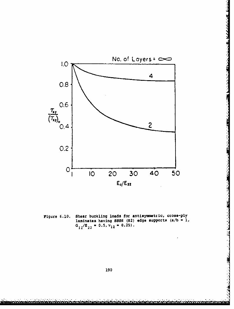
No. of Loyers .1.0 4":-
0.8.
0.67x'y
0.4
0 .2.
0 I0 20 30 40 50
E1,/E22
Figure 6.10. Shear buckling loads for antisuymetric, cross-ply.laminates having SSS (82) edge supports (a/b - 1,G 1 2/E 2 2 * 0.5, V1 2 " 0.25).
1901
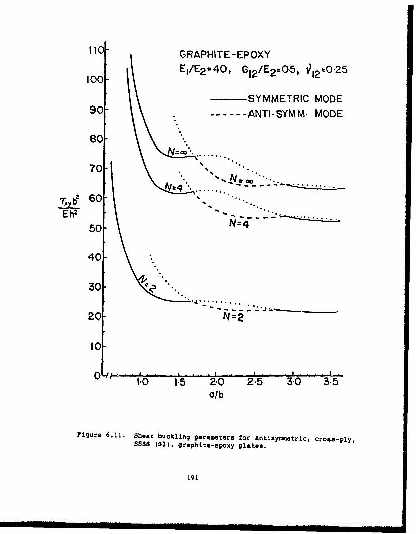
110 GRAPHITE-EPOXY
Ej/E 2 =40, G12 /E 2 -0.5l '12=0"25100-
SYMMETRIC MODE90 ...... ANTI-SYMM. MODE
80 ".
70"• . "_'.. . - . . . . . .
See a D
7;2 60
Eh2 " ..
50 N=4
40
30-'1
20N
I0 0 1 '-. .1 . .. ' . . . 1 ..d A . '0. 0 1.5 2.0 2.5 30 3.5
a/b
Figure 6.11. Shear buckling parameters for antisymwetric, cross-ply,SSSS (82), graphite-epoxy plates.
191
S ... ' i . . .. i. . . . .i . . . . . i . . . . i . . . | . . . .

F
30'
BORON -EPOXYEI/E2=IO, G12/E2=I/3, -•2022 .
.- SYMMETRIC MODE
25- -... ANTI-SYMM. MODE
20T b20 .:
""h -N""4::" :E h? z----
N=4
15-
N=2
1.0 1-5 2.0 2.5 3-0 3-50/b
Figure 6.12. Shear buckling parameters for antisyummetric, cross-ply,888$ (W), boron-epoxy plates.
192

16 GLASS- EPOXY
El/E 2 =3, G12 /E2 =0"5
151 =0-25012 02
14 SYMMETRIC MODE
- -ANTI-SYMM. MODE13
1l2
Eh 2
I I
10.% ° .. Q .
9-
7
1I0 1.5 2"0 2.5 3.0 35a/b
Figure 6.13. Shear buckling parameters for anytisymmetric, cross-
ply, SSSS (S2), glass-epoxy plates.
193
i ~ ~ ~ ~ ~ ~ -- --- ----II l ll l n l

6.2. SFSF
In Table 6.9 are listed the experimental buckling loads obtained
by Mandell and Kicher (34,35,172] for SFSP unsymmetrically laminated
plates having the simply supported edges subjected to uniaxial loading.
The plates are those described previously in Section 6.1 (Tables 6.3-
6.6). Theoretical results in all cases were calculated on the assumption
that the plate bends as a simply supported beam having no transverse
curvature or twist (see description of analysis in Section 3.6). Addi-
tional theoretical results obtained by the Ritz method using the reduced
bending stiffness matrix, as developed by Ashton [42], are also given
for most of the plates in Table 6.9.
Chailleux, Hans and Verchery 1174-176] also obtained experimental,
uniaxial buckling loads of SFSF plates (loaded edges with S4 conditions).Tests were conducted on nearly-square, angle-ply plates made of boron
fibers in an aluminum matrix, as described previously in Section 6.1.
Numerical results are given in Table 6.10, which may be compared with
results given previously in Table 6.8 for SSSS plates (and where additional
plate data is available).
Theoretical and experimental results for the buckling of uniaxially
loaded SFSF laminates composed of boron-epoxy and titanium layers were
found by Viswanathan, Soong and Miller f92].
6.3. CCCC
In the case of clamped edges, the transverse displacement and normal
slopes are everywhere zero. However, permitting various degrees of con-
straint in the inplane directions gives rise to four sets of boundary
conditions, in a manner similar to that used for simply supported edges
(see Section 6.1), viz
194
- • - -- - - - -•- - - - -----. -------. -...--

Table 6,9, Unlaxial buckling loads(-Nx, lb/in) for Mandell'sSFSF unsymmetrically laminatedplates
Plate Experimental Theoreticalno,
209a 20.7 62.323.7**
209b 19.7 62.323.7**
409a 38.5 70.642,7**
409b 36,1 70.642,7**
501 13.7 15.4502 36.6 43.4503 18.3 22.5
18.9**504 23.0 26.8
23.2**505 12.5 15.4506 39.1 42.6507 12.8 20.5
16.6**508 9.51 11.2
10.9**509a 15.4 23.9
17.6**509b 15,3 23,9
L - 17,6**
** obtained by the Ritz method, usingreduced bending stiffness matrix
Table 6.10. Buckling loads (kg) for uniaxially loaded, SFSF plateswith boron fibers in an aluminum matrix (see Table 6.8for other data).
Ply Critical loads (kg)
layup P P P
0-90 175 175 185
± 150 86.2 85.1 119± 30' - 80.4 -S45' 153 148.5 153±600 54.3 54.3 57.4+75° .,-
195
p•

cl: W U = 0an n
C2: w =wN u= 0 (6.10)
aw
C3: w n = N 0Dntan _n nt
awC4: w -LN N = 0
an n nt
Whitney [163,164] extended the series method used previously to
analyze SSSS(S4) plates [165,171] (see Section 6.1) to clamped edge condi-
tions. In this manner data was obtained for the buckling of biaxially
loaded (Ox = ay - constant, Txy - 0), ±450 angle-ply, square plates with
Cl edge conditions. Figure 6.14 shows the variation of -Gxha 2/E 2 2 h2
with El 1 /E 2 2 for plates haing 2, 4 and layers. The other material
properties used apparently were G12/E22 - 0.5 and v 12 0.25. Additional
data are given in Tables 6.11 and 6.12 for cross-ply and +450 angle-ply
plates, respectively, having two layers with E, /E = 40, G -/E 0 0.511 22 112 22
and v12 ' 0.25, for Cl, C2 and C3 types of edge constraints, and five
aspect ratios. Results from using orthotropic plate analysis with reduced
bending stiffnesses (see discussion preceding Section 6.1) are also pre-
sented. It appears that the results of Tables 6.11 and 6.12 violate a
fundamental principle of mechanics; viz, that the addition ot constraints
should only increase (or leave unchanged) the buckling load of a system.
Some numerical results for uniaxially loaded, CCCC plates were
obtained by Chia and Prabhakara [15,181) as part of a postbuckling analy-
sis of unsymmetrical laminates. The Galerkin method was used, with dis-
placements taken as the products of beam functions. Results are shown
in Table 6.13 for a set of cross-ply and angle-ply (+450) plates, each
composed of four graphite-epoxy plies (E l/E - 40, G 2/E2 a 0.5, V12 - 0.25).
These data were attained by using 9 terms of the double infinite series
of displacement functions. Zhang and Mathews [188] subsequently showed
that the results from the Galerkin method are very sensitive to the number
of significant figures kept in the computation of the beam functions.
Results given by them in Table 6.13 were achieved carrying 15 significant
196

S
60
- 0- 10 20 30 40 50
-E E / E t
Figure 6.14. Buckling parameters for biaxially-loaded CCCC (CI),
unsymetrically laminated, square, angle-ply plates.197
"0010 01397
Eo1 f-e
Fiue61.Bcln aaees o ixal-oddCC C)

Ih
Table 6.11. Buckling parameters -Oxa 2 /E h2 for biaxl-'loaded CCCC cross-ply plates having twr
a Edge conditions
b Cl C2 Reduced bendingstiffness
1 23.450 22.697 23.0682 11.360 11.352 11.3523 6.313 6.315 6.3154 4.967 4.968 4.9685 4.977 4.977 4.977
Table 6.12. Buckling parameters -%a 2 /E^ 2 b2 for biaxially-loadedCCCC± 45 angle-ply plates ýaving two layers.
a Edge conditions
b Reduced bending"" C I C2t stiffness
1 26.002 26.592 24.7652 24.655 27.767 21.8893 25.147 27.873 23.6864 23.168 25.790 22.8675 22.664 22.960 22.658
198
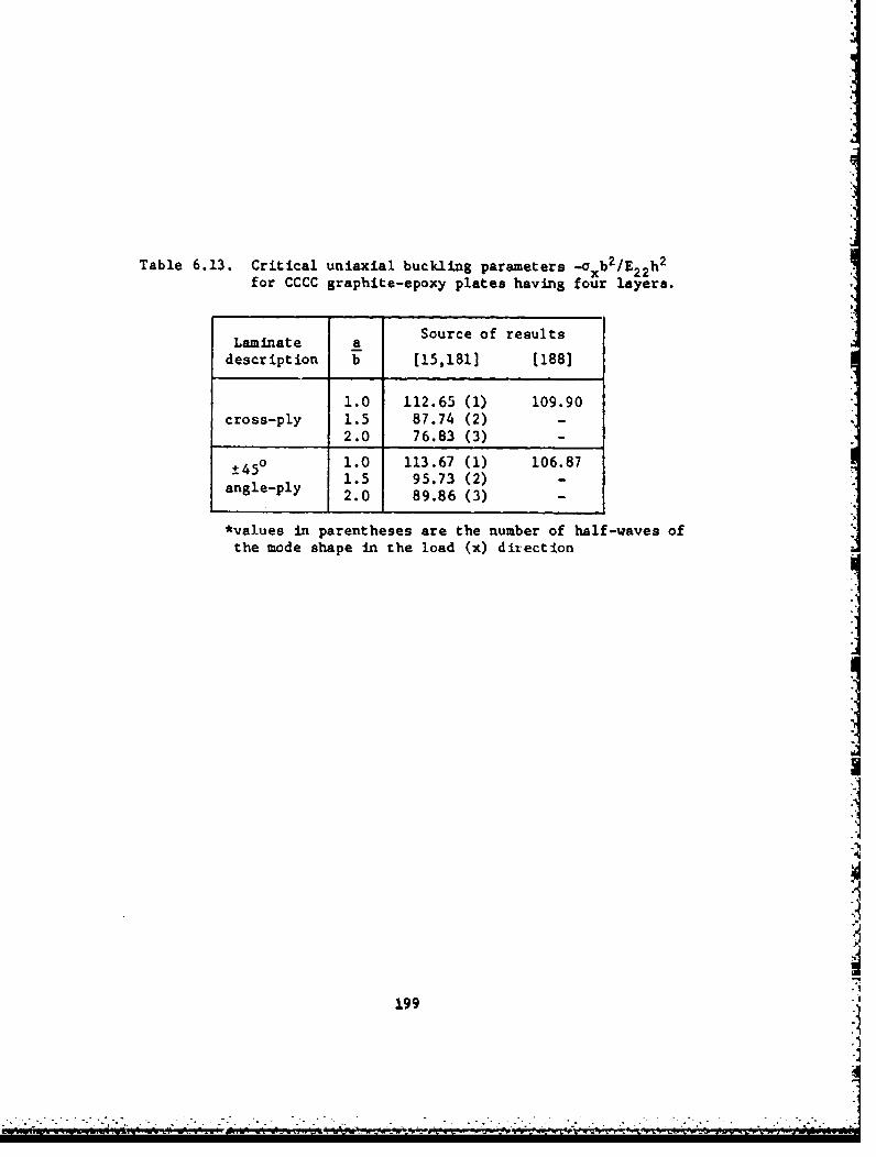
Table 6.13. Critical uniaxial buckling parameters --.. b2 /Ea2 h 2
for CCCC graphite-epoxy plates having four layers.
Source of resultsLaminate _adescription b [15,181] (188]
1.0 112.65 (1) 109.90cross-ply 1.5 87.74 (2) -
2.0 76.83 (3) -
+45° 1.0 113.67 (1) 106.871.5 95.73 (2) -angle-ply 2.0 89.86 (3) -
*values in parentheses are the number of half-waves ofthe mode shape in the load (x) direction 1
199."I

figures in the beam function parameters, whereas Chia and Prabhakara [3.51,181]
had used six significant figures.
20
6p
I t

CHAPTER VII. COMPLICATING EFFECTS
In this chapter, mcre complicated bifuLcation buckling problems
for laminated composite plates will be taken up. The complicating
effects will be seen to include: internal holes, shear deformation,
sandwich plates having laminated composite layers combined wita other
materials, localized buckling, nonlinear stress-strain relationships and
hygrothermal effects. Stiffeners will be discussed in Chapter IX.
7. 1. INTERNAL HOLES
Marshall [189) took up the problem of the buckling of a uniaxially
loaded, rectangular plate of dimensions axb containing a central, circular
hole of radius r (see Figure 7.1). All edges along the rectangular boun-
dary were simply supported, whereas the circular boundary was free. Test
plates were made of unidirectior.al glass cloth embedded in a polyester
resin matrix, yielding orthotropic plates having the following propertie.:
Ex - 3.1 GN/m 2 , Ey - 10.4 GN/m 2 , Gxy - 2.14 GN/r?, Vxy - 0.30. Theoreti-
cai results were obtained by assuming the tollowing internal stresses:
a-= z 2 (cos26 + (2-3z 2 )cos4e]
°x 2
= -2 {2 + Z 2 13cos26 - (2-3z 2 )cos4eJ} (7.1)y 2
aT Z2 [-sin26 + (2-3z 2 )sin49]2
where z a ro/r. The buckling problem was solved by means of the Ritz
method, with the buckled mode shape assumed in the form:
W =Cosx Cos + Be- C 2 2 (7.2)a b a b + (.
The first term of Equation 7.2 describes the overall mode shape, whereas
the second term accounts for localized displacements in the vicinity -i
201

yro
tt *1tttIt1tt1
F'igure 7.1. Uniaxially loaded plate with a central, circular hole.
202
V-S

0.7-
-' 0-6
0-s
0.3-0.2
0.1
0 0m.2 0.) 2., 0 6" " .7
Figure 7.2 Critical uniaxial buckling stresis ratio for 888li ortho-tropic plates with holes.
203
S. . .-.-.._ -,•; -r , .I~ . .. . .. . .. .. ..0.,1 02,.. 0r.3 0,4. 0 " """ " " - 04 .• 0-.7'

the hole [189]. B and C are constants determined by the minivnizing process.
Numerical data were obtained for square plates (250 - x 250 ma x 1.9 mm)
having ro/a 0, 0.1,...,O.7. These are shown in Figure 7.2. There the
continuous curve represents the result of the theoretical analysis and
the data points show the results of experiments conducted on three test
specimens. The ordinate 0o/1o is the catio the critical buckling stress
to that of the plate not having a hole.
The buckling of laminated composite square plates having central,
circular holes was also studied by Martin [190,191].
7.2. SHEAR DEFORKATION
Classical plate theory is based upon the Kirchhoff hypotheaist
"Normals to the midplane of the undeformed plate remain straight and
normal to the midplane during deformation." This assumption therefore
ignores the transverse shear deformation. Consideration of shear deforma-
tion results in added flexibility, which becomes significant as the plate
thickness increases relative to its length and width.
A quantitative theory which accurately provides the necessary correc-
tLon to provide for shear deformation has been available for thick beams
for at least 60 years. Generalization of isotropic plate theory to inolude
shear deformation was carried out by Raiesner [192,193] 40 years ago.
More recently, Ziegler [1941 showed that the effects of the inplans deforma-
tion inmediately prior to buckling are of the same order of magnitude
as, and in some cases even more than, the transverse shear deformation.
In thick plate theory one may express the total slopes of the deformed
midsurface at a typical point as
204
---- ; • .'• -•.": -. •.• - _. - _ _• : : -" - . .. . . - - .. . . --. '- '., , .- - - ',. . "_.- .

awT--x x + fx
aw (7.3)
7"_ *y + ly
where *x and 4y are the rotations In the x and y directions (i.e., rota-
tions about the y and x axes), respectively, due to bending and ý, and
fy are the slope changes due to shear. Shear deformation theory requires
a solution in terms of three independent variables, each of which is a
function of the two independent variables (x,y). The dependent variables
are typically taken to be w and either *, and *y or *x and fy, with the
remaining two variables determined by 3quations 7.3. The resulting set
of governing differential equations is of sixth order, which requires
specification of three boundary conditions per edge. This is in contrast
with classical plate theory and with bean theory (with or without shear
deformation) which only require fourth order equations and two boundary
conditions per edge. Further generalization to unsymmetrical laminates,
with the ensuing additional coupling between bending and stretching,
would result in a tenth order set of equations, as one finds for thick,
isotropic shells.
A major contribution to the analysis of laminated composite, thick
plates is the book by Ambartsumyan, which was translated from the Russian
in 1970 (13]. Recently, Bert [195] made an excellent analysis of various
thick plate theories as applied to laminated composite materials.
One set of differential equations governing the equilibrium of an
orthotropic plate in its small displacement, buckled configuration may
be adapted from pages 39 and 198 of the book by Ambartsumyan (13]. They
may be written as
205

3W a3w D 2 + a2%11 =3 +(D12+ 66 xaY2 1~ 3 1 (7.4a)
1 =0+ !-L(D'+D 6 6 + 2 Ox
23
a~3
1 3w + +D3w h 2 w i )22
(7.4b)
+ _i( 1D2 +Dss_ 66 B Y • 12 Y313 2
h•• +N • + 2N _ + N 0
where the Dij are as used in previous chapters, and where 0 13 and G 23
are the shear moduli relating the transverse stresses and strains. It
is seen that classical, orthotropic plate theory, governed by Equation
2.1, results when the shear stiffnesses G13 and G23 are set equal to
infinity, and Equations 7.4a and 7.4b are substituted into Equation 7.4c.
An exact solution to Equations 7.4 may be obtained in the case
when Nxy - 0 and the plate is simply supported along all four edges.
The corresponding boundary conditions are:
Along x = O,a : w - Mx - 4y - 0
(7.5)
Along y - O,b : w - My a *x " 0
It is remarked that since, for example, w - 0 along x - 0 implies
that Dw/ay - 0 along x - 0, as well, then y- 0 along x - 0 implies
that ýy - 0, as well. Thus, along all edges, not only are the total
tangential slopes zero, but both the shear and bending parts of total
i206
A-1

tangential slopes are each zero for the boundary conditions of Equations7.5. Equations 7.5 are exactly satisfied by assuming the functions
Ox A cos nmx sin n1ya b
Oy = B sin- mx cos nrya b (7.6)
w = C sin mx sin nfya b
with m, n - 1, 2,... Substituting Equations 7.6 into Equations 7.4, oneobtains (generalized from p. 200, [13])
a h(M)+ a h (n) 2 7 2 [D I)4 + 2 CW12 +2D 2 2
+ D +K (7.7)
where K, = .1-2 h-2 (G3 1 2 + G1_ n2b n10 DII M2+o D
10 a2 G 1 bh/L -a7 6 6 bj2
x D66 -+ D22 - (D12+D6 6 a) (7.8a)
[D aD() + 2 (D1 2 +2D 6 6) (n) 2 (a) 2 +D n
207

2h2[ (n M1 21 m2 n29K ay+1 n2 ) G (2 0 1- a13 66 )+ 23 66 a7 + 2
1 Thr4 0 m2 m2 Dhn2+ G 1 G 00 D + D n2) (D66 a-7 22 b-
13 2311a 66b
(7.8b)
-(D 1 2+D 6) 2(a 2(n 21
It is observed that in the case of no shear deformation, G13 and G23 are
infinite, K, - K2 - 0, and Equation 7.7 is the same as Equation 2.22 for
a classical orthotropic plate.
Ambartsumyan [13] made parametric studies for the uniaxial buckling
loads (ax - constant, oay - Txy - 0) resulting from Equation 7.7 for vari-
ations of the following material modulus ratios:
Ek Ek El E2
k -2 = G G (7.22 12 13 23 (79)
For uniaxial loading, critical loads occur always with n a 1. Nondimen-
sional buckling parameters -oxb 2/v 2D are listed in Table 7.1 for various
combinations of k1 , k 2 , k3 and a/b, with h/b taken as 0.1. The column
with k - 0 corresponds to classical theory (neglecting shear deformation).3
Also listed in Table 7.1 are the minimum values of -Oxb 2 /2 D 1, and the
corresponding a/b where they occur. It is seen that the buckling para-
meters all decrease with increasing k 3 .
Whitney [196] extended Ambartsumyan's [131 work to accommodate
laminated plates having layers with fibers not all parallel to the plate
edges. The exact solution used in Equation 7.6 was found to be valid
for SSSS angle-ply plates having large numbers of layers. Numerical
208
i ' ~ ' ~ I a iU i; I I

Table 7.1. Buckling parameters -axb 2 /n 2D for uniaxially loaded,SSSS orthotropic plates with 'Shear deformation (h/b - 0.1).
(a) k - k2 n 5.0, v12 -0.3
a k3b 0 2.0 5.0 10.0
0.35 9.093 7.682 6.241 4.7630.65 3.357 3.144 2.873 2.5160.95 2.194 2.105 1.984 1.8161.25 1.858 1.799 1.716 1.5961.65 1.817 1.769 1.700 1.5981.95 1.929 1.881 1.814 1.7122.25 2.116 2.066 1.995 1.8892.55 2.360 2.306 2.230 2.115
1.5954* 1.4820* 1.4629* 1.4336*1 1.8000 1.7488 1.6770 1.5694
* values of a/b where minimum buckling load occurs.
(b) ki - k2 2 2.0, v12- 0.3
ka 30 2.0 5.0 10.0
0.25 18.241 13.263 9.440 6.3920.45 7.250 6.335 5.335 4.2340.75 4.269 3.978 3.610 3.1300.95 3.769 3.569 3.305 2.9441.25 3.631 3.481 3.277 2.9861.45 3.737 3.599 3.411 3.1371.75 4.068 3.936 3.754 3.4852.15 4.738 4.601 4.411 4.126
1.1892* 1.1588* 1.1151* 1.0475*3.6241 3.4657 3.2469 2.9264
* values of a/b where minimum buckling load occurs.
209
I

(c) k, = 0.5, k2 = 1.0, v21 - 0.3
a k3b 0 2.0 5.0 10.0
0.25 20.545 14.915 10.570 7.1150.35 12.828 10.576 8.371 6.2120.55 8.331 7.519 6.561 5.4120.75 7.323 6.826 6.196 5.3721.05 7.532 7.167 6.683 6.0081.25 8.185 7.844 7.384 6.7281.45 9.101 8.763 8.301 7.6341.55 9.641 9.300 8.832 8.151
0.8409* 0.8036* 0.7489* 0.6605*n 7.2484 6.8026 6.1964 5.3267
* value of a/b where minimum buckling load occurs.
(d) k1 0.2, k2 = 1.0, v2 1 mf 0.3
a k3b 0 2.0 5.0 10.0
0.25 20.840 15.547 11.291 7.7840.35 13.304 11.239 9.135 6.9870.55 9.346 8.601 7,b91 6.5520.65 9.007 8.435 7.708 6.7510.85 9.525 9.087 8.507 7.6960.95 10.149 9.734 9.177 8.3851.15 11.897 11.489 10.931 10.1191.25 12.981 12.565 11.991 11.150
0.6688* 0.6386* O.5937* 0.5177*9.0001 8.4329 7.6577 6.5377
* values of a/b where minimum buckling load occurs.
210

results were found for the uniaxial buckling of a square plate with +450
angle-ply stacking sequence and with E /E2 * 40, G 1 /E 2 - 0.6, G2 3/E 2 2 a 0.5,
V1 2 - 0.25. Variation of the buckling load parameter -oxa 2/E 2h2 with
the thickness ratio, a/h, is shown in Figure 7.3. It is seen that the
buckling load for a/h - 20 is considerably less with shear deformationtheory (SDT) than with classical plate theory (CPT). Furthermore, the
shear deformation effect is much more significant for the laminated com-
posite plate than it would be for an isotropic plate.
Vinson and Smith [1971 derived an expression for the strain energy
of an orthotropic plate, considering the effects of shear deformation,
which can be put into the following form:
VS ' + 2D1 ~x + D2(±)A
6 ) 6 x ( x
+ -- h [G 2 + G2] dA12 13 X 23 y ) d
(7.10)
From Equations 7.3 it is seen that when shear deformation is excluded
(Cx - *y = 0), Equation 7.10 reduces to the bending strain energy of an
orthotropic plate, given by Equation 2.3. (In the limit, for example,
as G13 increases, Ox vanishes, with the product G1 3Ox remaining finite
and proportional to the shear stress, and G13 therefore vanishing.)
Thus, Equation 7.10 together with the potential energy due to inplane
forces, Equation 2.4, is useful for analyzing the buckling of
orthotropic plates with arbitrary edge conditions by Rayleigh-Ritz
methods when shear deformation is included.
211

60 • •P
40 -SOT
E2h
20a
020 40 60 60 100
a/h
Figure 7.3. Buckling of a uniaxially loaded, SSSS, ±450 angle-ply,
square plate having an infinite number of layers, with
and without shear deformation.
212
S_ ,- ... - - [ •;• ::••• -],:,-;,-..-.. .- -- .- -,.: -_-. -- _ --.. - - .- ,.-.. .-... .--.... ... . -..

In using Rayleigh-Ritz methods with Equation 7.10 the typical proce-
dure would be to specify three sets of functions, either w, Ox, *y or w,
ýx, *y, with Equations 7.3 providing the required relationships among
them. Vinson and Smith [1971 derived additional, approximate relationships
among these functions from considerations of beam behavior with shear
deformation present. These are:
aw h2ElI 6N(+
x x 0 GI 5c h
aw h 2 E2 + N (7.11)= ++ 5G23 h
Substituting Equations 7.3 and 7.11 into Equation 7.10 results in a lengthy,
but manageable, expression for VS in terms of the single dependent vari-
able w(x,y). The detailed form of this functional is given in [197].
Using the approximate strain energy functional described above,
along with the displacement function given by Equation (2.8), numerical
results were calculated for SSSS orthotropic plates made of unidirectional
boron fibers (56% in volume) embedded in an epoxy matrix [197]. The
corresponding orthotropic elastic moduli are:
E = 32.5x10 6psi , F - 1.84xlO6 psi
G 1 G 0.642x10 psi , G23 a 0.361xl0 psi12 13 2
112 " 0.256, v2 1 - 0.0146.
It was found that the differences between buckling loads according to
classical and shear deformation theories were small for thickness ratios
h/a - 0.02 and 0.01, but became significant for thicker plates. Critical
loads occurred for n - 1. Numerical results for the buckling parameter
CFXTr 2/G are presented in Table 7.2 and Figure 7.4 for h/a - 0.1, and in
13
213
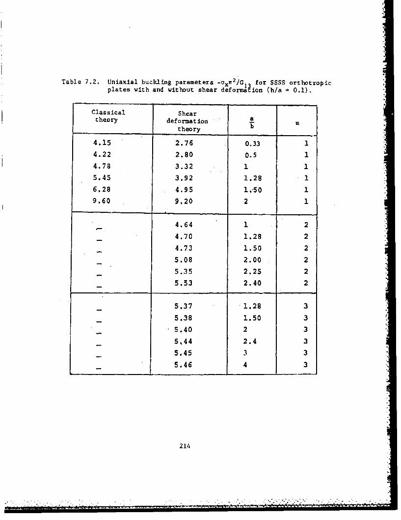
Table 7.2. Uniaxial buckling parameters -ox 2/Gl for SSSS orthotropicplates with and without shear deformaE ion (h/a = 0.1).
Classical Sheartheory deformation a
theory b
4.15 2.76 0.33 14.22 2.80 0.5 1
4.78 3.32 1 15.45 3.92 1.28 16.28 4.95 1.-50 19.60 9.20 2 1
4.64 1 2
4.70 1.28 2
4.73 1.50 2
5.08 2.00 2
5.35 2.25 2
5.53 2.40 2
5.37 1.28 3
5.38 1.50 3
5.40 2 3
5,44 2.4 3
5.45 3 3
- 5.46 4 3
21
214'
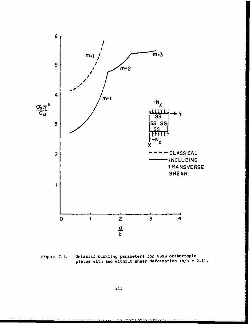
6 II
5 ii Ms2//
4'
-N x
x
2 CLASSICALINCLUDINGTRANSVERSESHEAR
0 I 2 3 4
ab
FiguLe 7.4. Unjaxi3l buckling parameters for SSSS orthotropicplates with and without shear deformation (h/a - 0.1).
215

Table 7.3. Uniaxial buckling parameters -a x2/G13 for SSSS orthotropicplates with ano without shear deformation (h/a = 0.04).
Classical Sheartheory deformation b m
theory
.658 .615 0.33 1
.669 .625 0.5 1
.756 .712 1 1
1.518 1.482 2 1
4.268 4.231 3 1
2.678 2.051 1 2
3.022 2.343 2 2
3.958 3.244 3 2
6.034 5.124 4 2
6.649 6.200 4.2 2
6.795 4.144 3 3
7.978 4.654 4 3
8.311 6.160 4.2 3
8.494 6.669 4.3 3
8.648 7.640 4.4 3
216
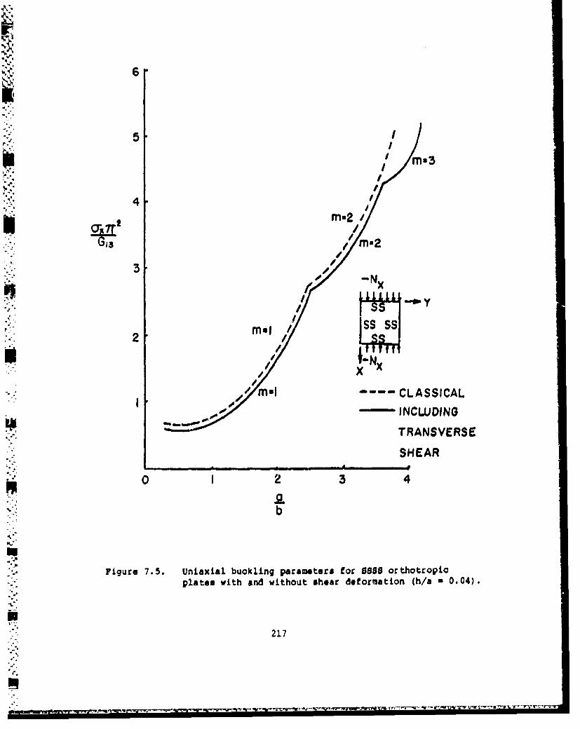
6
" 3 //
Mx3
44E
0 I 2ir mn 40/
21
S INx
0 m2 //4
Fiur 7.5. UnailbclngprmtrNo 58 rhtoplates wihadwtotserdeomto hX00)
217 -- CASIA
...... W....

Table 7.3 and Figure 7.5 for h/a - 0.04. Additional results are also
available for h/a - 0.02 and 0.01 [197].
Exact solutions of the three-dimensional elasticity equations for
the buckling of cross-ply laminates having four edges simply supported
are also possible. These ware obtained by Srinivas, Jogs Rao and Rao
[198,199] and by Moor [200]. It was determined that shear deformation
theory gave accurate results for thickness/width ratios of at least 0.3.
An example of the type of results found may be observed in Figure 7.6
where the uniaxial buckling load parameter -Oxb2/Z2h2 is plotted versus
a/b for plates having even numbers of layers (NL), thereby yielding unsym-
metrical laminates, and h/a w 0.1. Material properties used for each
layer were: 21/E2 * 30, G1 2 /E 2 u 0.6, G1 3/E 2 a 0.5, and v 1 2 ' 0.25.
The curves of Figure 7.6 show very close agreement between the shear
deformation theory (SDT) and elasticity solution values. However, the
classical plate theory (CPT) differs considerably especially for NL - 4
or greater. On the other hand, for eyhoetrically laminated plates the
error in classical plate theory was fouid to decrease as NL increases.
Turvey [2011 incorporated the reduced stiffness method (see Chapter
VI) into shear deformation plate theory for unsymmetrical laminates,
thereby arriving at a sixth order set of governing differential equations.
Comparison with Noor's [200] three dimensional results for SBS8 plates
showed close agreement of uniaxial buckling loads for square plates having
h/b - 0.1. At least two other references also deal with the buckling of
SS5 plates, including shear deformation effects 1202,203].
Vinson and Smith 1197] followed the approximate procedure described
earlier in this section to solve uniaxial buckling problems (Qx w constant,
UY a Txy - 0) for BCBC orthotropic plates having shear deformation. A
buckling mode shape wat assumed in the form
218

so-
70-
60 * I
2NL 4
E2tI 40
so
0.6 1. 1.1 S. 0 2 -.1 1!0
I.b
Figure 7.6. Comparison of exact elasticity, classical plate theory(CPT) and shear deformation theory (SDT) solutions foruniaxially loaded, 5588 cross-ply laminates.
219
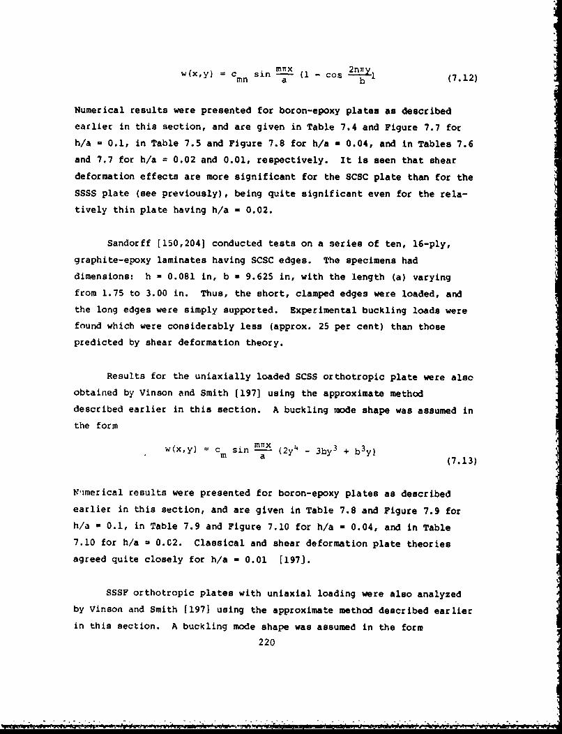
w(x,y) = C sin m -x 2nivymn • i - os~l(7.12)inn a b
Numerical results were presented for boron-epoxy plates as described
earlier in this section, and are given in Table 7.4 and Figure 7.7 for
h/a = 0.1, in Table 7.5 and Figure 7.8 for h/a - 0.04, and in Tables 7.6
and 7.7 for h/a = 0.02 and 0.01, respectively. It is seen that sheardeformation effects are more significant for the SCSC plate than for the
SSSS plate (see previously), being quite significant even for the rela-
tively thin plate having h/a - 0.02.
Sandorff [150,2041 conducted tests on a series of ten, 16-ply,
graphite-epoxy laminates having SCSC edges. The specimens had
dimensions: h - 0.081 in, b - 9.625 in, with the length (a) varying
from 1.75 to 3.00 in. Thus, the short, clamped edges were loaded, and
the long edges were simply supported. Experimental buckling loads were
found which were considerably less (approx. 25 per cent) than those
predicted by shear deformation theory.
Results for the uniaxially loaded SCSS orthotropic plate were also
obtained by Vinson and Smith (197] using the approximate method
described earlier in this section. A buckling mode shape was assumed in
the form
w(x,y) = c sin mnx (2y4 - 3by 3 + b 3 y)m a (7.13)
9'imerical results were presented for boron-epoxy plates as described
earlier in this section, and are given in Table 7.8 and Figure 7.9 for
h/a - 0.1, in Table 7.9 and Figure 7.10 for h/a - 0.04, and in Table
7.10 for h/a - 0.C2. Classical and shear deformation plate theories
agreed quite closely for h/a - 0.01 [197].¶
SSSF orthotropic plates with uniaxial loading were also analyzed
by Vinson and Smith [1971 using the approximate method described earlier
in this section. A buckling mode shape was assumed in the form
220

Table 7.4. Uniaxial buckling parameters -c xr 2 /G for SCSC orthotropicx 131plates with and without shear deformation (h/a = 0.1).
Classical Sheartheory deformation m
theory b
4.15 2.84 0.33 1
4.32 2.95 0.5 1
5.90 4.30 .1 1
8.41 6.60 1.28 1
11.77 11.00 1.50 1
16.47 5.40 0,33 2
5.43 0.5 2
5.45 1 2
5.58 1.28 2
5.65 1.50 2
5.84 1.75 2
37.6.3 5.75 1 3
5.77 1.28 3
5.79 1.50 3
5.80 1.75 3
5.83 2 36.55 2.75 3
221

II
6=1 M=26 - I -Nx
4 X
O'-T --- CLASSICAL
U- INCLUDING3 TRANSVERSE
SHEAR
2
0 I 2 3 4ab
Figure 7.7. Uniaxial buckling parameters for SCSC orthotropicplates with and without shear deformation (h/a - 0.1).
222
_'.. - --- " .;__'='. . -. " .'_'_,' " " .". ." •.• ,.,. -. . - p.' • _.. "., ... p•• ' ' :, " -.-. "_•,••'.•

Table 7.5. Uniaxial buckling parameters -for SCSC orthotropicplates with and without shear deformalion (h/a - 0.04).
Classical Sheartheory deformation a
_theory b
.6688 .6233 0.33 1
.6919 .6490 0.5 1
.9497 .8878 1 14.2236 3.7641 2 1
17.6561 14.2650 3 1
2.7681 2.1091 1 .2
3.7988 2.9783 2 25.1604 4.1026 2.5 2
7.5105 6.0227 3 2
8.1292 8.1340 3.1 2
16.8944 15.6564 4 2
6.0205 3.4805 1 3
6.6364 3.9571 2 3
7.3565 4.5944 2.5 3
8.5428 6.0289 3 3
8.8511 6.6599 3.1 3
223
)
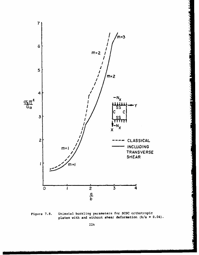
7
mz2I
5 M =2
S~//
4 [lll/ m N/r:2
4 ( -Nx
iIG 3 II yN
/x
2 / - CLASSICAL
m= / INCLUDINGm // TRANSVERSE
/ ' S H E A R
rnMl
0 I 2 3 4ab
Figure 7.8. Uniaxial buckling parameters for SCSC orthotropicplates with and without shear deformation (h/a - 0.04).
224

Table 7.6. Uniaxial buckling parameters -ax r2 /G1 for SCSC orthotropicplates with and without shear deformalion (h/a 0.02).
Classical Sheartheory deformation mtheory
.167 .163 0,33 1
.238 .234 1 1
1.058 .978 2 14.426 4.110 3 1
13.342 11.755 4 1
.692 .645 1 2
.950 .901 2 21.881 1.734 3 2
4.234 3.681 4 2
8.9.46 7.648 5 2
1.658 1.423 2 3
2.134 • 1.847 3 3
3.264 2.828 4 35.506 4.646 5 3
9.446 8.952 6 3
225 •1

Table 7.7. Uniaxial buckling parameters -oa r2 /G for SCSC orthotropicx 13plates with and without shear deformation (h/a 0.01).
ClassLcal Sheartheory deformation m
theory
.04330 .04320 0.5 1
.05936 .05916 1 1
.2640 .2628 2 1
1.1034 1.0854 3 1
.1730 .1708 1 2
.2374 .2362 2 2
.4694 .4637 3 2
1.0558 1.0296 4 2
2.2584 2.1854 5 2
.5342 .5154 3 3
.8117 .7871 4 3
1.3815 1.3131 5 3
2.3750 2.2176 6 3
3.9811 3.6416 7 3
226
~ ~;~~y -~--..--j,~- - .. .. . . -.. . . .. . . . . . .. . . . . °

Table 7.8. Uniaxial buckling parameters -o xr 2 /G for SCSS orthotropic
plates with and without shear deformation h/a 0.1).
Classical Sheartheory deformation b m
theory
4.0736 2.8089 0.33 1
4.1733 2.8879 0.5 1
5.0930 3.7133 1.00 1
5.9305 4.8019 1.2 1
6.2702 5.3300 1.26 1
4.9992 1.00 2
5.0994 1.2 2
5.1902 1.26 2
5.2845 1.30 2
5.8102 1.50 2
5.7150 1.00 3
5.7180 1.30 3
5.7200 1.50 3
5.9200 2.00 3
227

6
5
/ -Nx
4N
CLASSICAL
INCLUDI NG
TRANSVERSE2
SHEAR
0 I 2 3 4
a
Figure 7.9. Uniaxial buckling parameters for SCSS orthotropicplates with and without shear deformation (h/a - 0.1).
223

Table 7.9. Uniaxial buckling parameters -.a r2 /G1 3 for SCSS orthotropicplates with and without shear deformation (h/a 0.04).
Classical Shea_theory deformat ion b m
theoryb
.6622 .6177 0.33 1
.6863 .6255 0.5 1
.8165 .7437 1 1
2.4410 2.4226 2 1
8.8285 8.6127 3 1
3.2660 2.6505 2 2
5.1655 4.8650 3 2
5.4792 5.2780 3.1 2
6.1333 6.0120 3.3 2
6.7370 6.7012 3.4 2
7.3472 5.3040 3 3
7.5121 5.6500 3.1 3
7.8838 6.4445 3.3 3
8.6020 6.6982 3.4 3
229

61
i:M=2
5
4/-C S A
ai2
0 IS23
-N
2 x
M I TRANVERS
b0 1 2 4
Figure 7.10. Uniaxial buckling parameters for SCSS orthotropicplates with and without shear deformation (h/a ,,0.04). •
X5
230
v m:- TRANSVERSE .

Table 7.10. Uniaxial buckling parameters -ox7r 2 /G 1 3 for SCSC orthotropic
plates with and without shear deformation (h/a - 0.02).
Classical Sheartheory deformation a
theory b
.1628 .1624 0.33 1
.1668 .1660 0.5 1
.2036 .2030 1 1
.6080 .6078 2 1
2.1980 2.1970 3 1
.8144 .7819 2 2
1.2860 1.2659 3 2
2.4256 2.4056 4 2
4.7086 4.6875 5 2
1.8288 1.6239 3 3
2.4084 2.2305 4 3
3.5136 3.4669 5 3
5.4186 5.2174 63
231
','•~t* r•- •,- - •,•-•-• -• • :• •t • •-*r w•- r•- • *-- •, • "•--r•-'•r•r*•-'dr•r•*•• -. r•'-• • -•- r

i-
Table 7.11. Uniaxial buckling parameters -vxw2/G for SSSF orthotropicplates with and without shear deformaihon (h/a - 0.1).
Classical Sheart heory deformation a
theory b
.173 .171 0.33 2
.260 .256 1 2
1.045 1.028 3 2
1.631 1.380 0.33 20
1.720 1.451 1 20
2.500 2.132 3 20
4.871 3.940 0.33 60
4.958 4.040 1 60
5.750 5.100 3 60
232

Table 7.12. Uniaxial buckling parameters --a w2 /GI 3 for SSSF orthotropicplates with and without shear deformation (h/a - 0.04).
Classical Shear atheory deformation b m
theory
.00694 .00695 0.33 2
.01042 .0105 1 2
.0417 .0418 3 2
.0654 .0652 0.33 20
.0689 .0687 1 20
.100 .0996 3 20
.1954 .1917 0.33 60
.1989 .1950 1 60
.230 .225 3 60
233

61
E- G- EX/X60
5 -N
4
-- CLASSICAL3 - INCLUDINGI
TRANSVERSESHEAR
011000I
0 2 3 4ab
Figure 7.11. Uniaxial buckling parameters for SSSF orthotropicplates with and without shear deformation (h/a -0.1).
234
,4

w(x,y) = Cm s in a• (7.14)i a
Critical loads were found to occur always with m - 1. Buckling parameterswere calculated for unidirectional composites and were found to depend
upon only one material modulus ratio: E1/G1 3. Numerical results forxIT2 /G3 are listed in Tables 7.11 and 7.12 for h/a - 0.1 and 0.04, respec-
"tively for a/b - 0.33, 1, 3 and EI/G -2, 20, 60. Data for h/a - 0.11 /G13
are also plotted in Figure 7.11. No significant differences between
classical and shear deformation theories were found for h/a - 0.02 or
0.01.
Some data for the buckling of CCCC plates including the effects of
shear deformation were obtained by Davenport and Bert (205-2071 as part
of a shell analysis, but no direCt comparisuaoi with classical plate theory
were made. Results for SFSF plates including shear deformation effects
are also available [32,208,209]. Other buckling studies for laminated
composite plates with shear deformation include (210-2121.
7.3. SANDWICH PLATES WITH SOFT CORES
The use of sandwich plates consisting of orthotropic or anisotropic
face sheets separated by core material has become widespread, for such
plates are capable of providing lightweight construction. For decades
plywood has been used for the face sheets. More recently the fiber com-
posites have been used, especially for aerospace applications. Core
materials may be considered as either homogeneous (e.g., foam) or hetero-
geneous (e.g., hexagonal or honeycomb cells, or corrugated).
Early experimental work to determine buckling loads was conductedby Boller f2131 on sandwich plates having glass-cloth laminate face sheets
and either end-grain balsa or cellular cellulose acetate cores. Various
edge conditions were considered. Experimental results were compared
235
N. A

with theoretical values given by formulas derived by March and Smith
[214]. Modifications were made in the formulas to account for shear
deformation in the cores. These and more recent references 1215-218]
are indicative of the considerable amount of work on buckling of laminated
composite sandwich plates which has taken place at the U.S. Forest Products
Laboratory.
Pearce and Webber 1219-221] made a theoretical and experimental
study of uniaxially loaded, SSSS sandwich plates composed of fiber-rein-
forced, face sheets and honeycomb cores. A set of differential equations
was derived, and numerical results were obtained for a square plate having
face sheets composed of +450 angle-ply laminates and a honeycomb core of
aluminum. It was shown in a specific example that a sandwich plate having
carbon fiber-reinforced face sheets would only need to weigh approximately
one-half as much as one using aluminum face sheets to fail at the same
buckling load.
Vinson and Shore [222] analyzed the buckling of sandwich plates
made of a web-core construction (see Figure 7.12) using orthotropic materi-
als. Three types of instability were considered:
1. Overall plate buckling
2. Local face buckling in the region from A to B (Figure 7.12)
3. Web element buckling.
Optimization studies were conducted with faces and cores made of different
materials. It was shown that optimum design occurs when the weight of
the core material is half that of the facing material, and that boron-
epoxy and graphite-epoxy materials provide lower weight designs than do
other materials.
Housner and Stein [68] proposed a simple correction in orthotropic
or anisotropic plate buckling loads to accommodate sandwich plates. This
requires only multiplying the critical stress by [1-(t/h) 3 ], where t is
236

I
tf,A , C
PITCH :
Figure 7.12. Cross-section of web-core construction.
237

the thickness of the core and h is the total thickness of the plate.
This correction factor is based upon the following assumptions:
1. The plate is symmetrically laminated.
2. Bending-twisting coupling is negligible (i.e., each layer has
the same fiber orientation angle (e), except for sign).
3. The core carries no load and undergoes no shear deformation
(or its shear modulus is negligibly small).
It was pointed out that for the second assumption to be valid, "it may
be necessary that t/h to be nearly unity, and that the amount of material
in either cover oriented in the +0 and -0 directions be equal.w
Hyer and Hagaman [223] conducted buckling tests on sandwich plates
having face sheets composed of layers of woven fabric, and cores made of
Hexcel glass-reinforced polymide honeycomb. The plates were loaded uni-
axially, with the loaded edges clamped and the other edges either simply
supported or free.
Zubchaninov [2241] analyzed the stability of three-layer plates
having a central layer of metal sandwiched between glass-reinforced plastic
outer layers. An example is presented for a rectangular plate in pure
shear.
A number of other references are also available dealing with the
buckling of sandwich plates made of laminated composites 1225-232].
7.4. LOCAL INSTABILITY
The effects of delamination and delamination growth upon the buckling
of composite plates were examined by several researchers 1233-235]. Delami-
nation is the result of either imperfection in the manufacturing process,
or is due to developments during the life of the laminate, such as impact
by foreign objects. Delaminations may cause a reduction in the overall
238

stiffness of the plate, thereby reducing its buckling loads. Further,
delaminations may grow, depending upon the loading and the toughness of
the material. Clark [ also considered the buckling of laminates
having discontinuous bonding.
Harris, Crisman and Nordby 1225-227] studied the local instability
of sandwich plates having facings made of fibrous composite plies. Four
types of instability were discussed 1226]. These included:
1. Overall plate buckling.
2. Shear crimping
3. Dimpling, or intercellular buckling
4. Face-wrinkling.
These types of buckling are illustrated in Figure 7.13. Face-wrinkling
may occur with either an inward or outward displacement of the face sheet
relative to the core. Outward buckling involves either a tensile failure
of the bond between the core and the facing, or a tensile failure within
the core. Inward buckling may be accompanied by compression failure in
the core. Face-wrinkling is typically analyzed either by treating the
face sheets as beams on elastic foundations, or by a quasi-elasticity
approach. Experimental results were obtained for sandwich plates of two
types: (1) fiberglass face sheets with aluminum, honeycomb cores and
(2) plywood face sheets with foam cores. It was pointed out that experi-
mental results are typically lower than theoretically predicted values,
and that thIs may be due to initial waviness (i.e., deviation from flatness)
nf the face sheets [226]. The local instability fail-,' of sandwich
plates having composite face sheets was also treated by Fogg (see pp.
5-0 to 5-13 in [32 ]), Pearce and Webber [219-221], and Vinson and Shore
"[222](see Section 7.3).
Biot [237] studied the localized edge buckling of a laminated com-
posite plate. The theory developed to deal with this problem included
couple stresses and stress-gradient dependence of the strain. This theory
was subsequently extended to iuoe general laminated plate analysis [238].
239

,.FACING
FACINGCORE
t tttt ttA.- GENERAL BUCKLING B.- SHEAR CRIMPING
HONEYCOMB ' f lr'ION
CORE FROMCORE
CORE- CRUSHING
t t - t tt t t t t t
C.- 0IMPLJNG 0.ID WRINKLING OF FACINGSOF FACINGS
Figure 7.13. Types of buckling failure for soft-core sandwichplates.
24u
ow ..... .. . . .* , . . -

7.5. INELASTIC MATERIALS
This section will consider laminate comroites made of materials
which are not linearly elastic.
The buckling of cross-ply plates with nonlinear stress-strain varia-
tion was analyzed by Morgan and Jones [239]. The nonlinear behavior was
characterized by assuming
E. A [1 - B C (7.15)
for each of the material moduli, where A, B, and C are constants to be
determined experimentally for each material. U is the strain energy
density, given by the integrand of Equation A.41, and Uo is a constant
used to nondimensionalize U. Typical stress-strain curves for fiber-
reinforced composite materials are shown in Figure 7.14. The equations
of equilibrium tor the buckled configuration (Equations 6.1) in the most
general case of an unsymmetrical laminate) are satisfied incrementally
by an iterative numerical procedure as the plate undergoes buckling defor-
mation.
Numerical results were obtained for SSSS, cross-ply laminated plates
composed of boron-epoxy, graphite-epoxy and boron-aluminum materials
[2391. The constants A, B, C associated with each composite material to
be used in Equation 7.15 are listed in Table 7.13. The values of inplane
Poisson's ratio (v12) used were 0.225, 0.38 and 0.275, respectively.
Values of o* listed for a few of the material moduli in Table 7.13 are
limiting values of stress beyond which equation 7.15 is no longer valid.
At such a point on the atress-strain curve a linear extension is added
having a slopv given by the value of E* in Table 7.1.3.
Figure 7.15 shows the nondimensional buckling stress resultant Nx
as a furction of Plate thickness for SOSS plates coni6itInq uf a dingle
241

Si
ILI
E --..2 E2 -
2112
/ 10-1 2
Figure 7.14. Typical stress-strain curves for fiber-reinforced com-posite materials [239].
242
.I

Table 7.13. Constants used in Equation 7.15.
A B C o* E*Material Modulus (GN/m 2 ) (KN/m 2 ) (GN/M 2 )
Boron- E 208 0 1 - -
E 19.8 0 1 - -epoxy 2 5.52 0.0628 0.462 64.1 0.331
Graphite- E10 159 0 1 - -Ephie 2 8.76 0 1 - -
eGo12 6.72 0.00144 1.13 88.3 0.779
Boron- El 210 0.00008 1.042 1380 165alBornu E 186 0.05814 0.723 155 25.0aluminu G 02 0.154 -399 -0.676 - -
243

1.0 .SOR11ON-EPOXY--
GRAPHrtE-POXY
"S.6Nx tNEANLINEAR
1 -N 12 cm.
SO cm.
.2-
O 1 2 4 5
h, Cm.
Figure 7.15. Ratio of nonlinear to linear elastic buckling loadsfor boron-epoxy and gr ite-epoxy, SSSS, unidirec-tiornal laminates.
2441

ply, with the loading along the direction of the fibers [2391. Nx is
divided by the value of Nx which would exist for a linearly elastic ma-
terial (obtained by setting B n 0 in Equation 7.15 for all moduli). This
ratio is seen to decrease from 0.95 to 0.87 for a boron-epoxy laminate
as h increases from 1 cm to 3 cm. For graphite-epoxy, the corresponding
ratios are 0.98 and 0.79. The buckling loads increase as h increases
for both the linear and nonlinear elastic materials. Similar plots are
shown in Figure 7.16 for a unidirectional boron-aluminum laminate. The
total nonlinearity effect is observed to be stronger for this material
than for those in Figure 7.15, the ratio of buckling stress for the non-
linear material to that of the linear material being only 0.35 for h - 1 cm.
In addition, the effects of nonlinearities of each modulus taken separately
is depicted. The shear nonlinearity is most significant for thicknesses
less than 1 cm; however, the nonlinearity in E2 is most important for
h > 1 cm. For three layer (00/900/00), cross-ply laminates similar be-
havior was found, with essentially no dependence upon aspect ratio (a/b)
[2391.
For unsymmetrically laminated, cross-ply plates made of boron-
epoxy, the effect of nonlinearity in modulus was found to be small. How-
ever, for boron-aluminum laminates very significant effects were uncovered,
azý may be seen in Figure 7.17 [239J. The linearly elastic buckling loads
with 2, 4 and an infinite number of layers are very close to each other
and are shown on a single curve in Figure 7.17 because EI /E2 is small,
causing small bending-stretching coupling. However, E1 /E 2 increaseswith load for the nonlinear case, causing the corresponding curves in
Figure 7.17 to be much lower. Finally, the variation in -Nxb 2 /E 2 h3 with
number of layers in a boron-epoxy, unsymmetrically laminated, cross-ply
plate is shown in Figure 7.18, considering coupled (exact) and uncoupled
(orthotropic), and linear modulus and nonlinear modulus solutions.
Hahn [240] in an earlier paper analyzed the buckling cf +450 angle-
ply plates having nonlinear stress-strain relationships. The elastic
245
• • " • • • • -• "• •' •'••' ":--" • " • " -r'•'• r • 'e • ' -•-" • 'r " e~u "•' ='-° .5

1.0
.6 Ia NONUNEARITY ONLYG12 NONLINEARITY ONLY
q.4
N6 .6
LINEAR1E N N I E R T
.22
k25 cm.
0 .5 o ,. 2.0 -2.5 -
Figure 7.16. Ratio of nonlinear to linear elastic buckling loads forboron-aluminum, SSSS, unidirectional laminates.
246
- - - --

-Nx --" •2Scm.
4a I a 1.25 cm.
S~NUMBER
NONLINEAR SOLUTIONS
000 2
a/b
. Figure 7.17. Uniaxial buckling loads of unsymmetric, SSSS, cross-ply, boron-aluminum plates.
L41
247
I

12.5
ORTHOTROPIC ('Bj 1:O)10NOLNA
ORHTROPIC (61i w 0)N~NR
I NOLINEAR EXACT
25
hc 1.25 cm.
* 0 20 40 60 s0 100
NUMBER OF LAYERS
Figure 7.18. tlniaxial buckling loads of unsymmetric, SSSS, cross-ply, boron-epoxy plates.
248

moduli were assumed to vary quadratically. In one example for a symmetri-
cally laminated, SSSS plate a small decrease in buckling load due to the
nonlinearity was found. Another paper which deals with the buckling of
a borcn-epoxy plate having nonlinear stresu-strain equations is that by
Durocher and Palazatto [241,242].
Teters [243] used flow theory to describe the plastic properties
of orthotropic plates undergoing buckling. Shear deformation effects
were also included, which were found to be important if E /G13 is large.
For E1/G 1 3 = 60 and a/b = 20, inclusions of shear deformation decreased
the critical stress by 45 percent.
7.6. HYGROTHERKAL EFFECTS
Two effects of the external environment may cause significant in-
ternal strains, thereby affecting buckling loads -. hygroscopic (i.e.,
moisture absorption) and thermal. Both moisture absorption and tempera-
ture increase serve to expand a plate causing internal compressive stresses
due to edge restraints or differential expansion. These effects in the
laminated composite plate buckling problem apparently were first jointly
taken up by Whitney and Ashton [244 ].
An interesting situation was found to develop in plates using graphite
fibers, for these fibers have negative values of thermal expansion coeffi-
cient in the axial direction. It was found that certain orientations of
angle-ply layups for graphite-epoxy plates having certain inplane boundary
constraints can be buckled by lowering the temperature rather than raising
it [244]. This may be seen in Figure 7.19 which is for a plate of aspect
ratio (a/b) of 3 clamped at two opposite edges and free at the other two
edges. The nondimensional buckling temperature change am(.ýT)(b/h) 2 is
plotted versus angle-ply orientation angle (0), where qm is the thermal
expansion coefficient of the matrix material, and .1T is the temperature
2.,, 9

400 l'-
300 I
200 I
I-I
.U IooI
-100 I0 -
! bI a --3b x
-200
-300 I -
I .-400- -
00o 100 20'0 300 400450 900
.'9
Figure 7.19. Thermal buckling of a CFCF symmetrically laminated,graphice-epuxy plate.
24
250 --

increase. The plate is composed of 4 layers symmetrically stacked (+0,
-0, -0, +0), and is subjected to a uniform temperature rise. For fiber
orientations 00 < 0 <17.50, the laminate has a negative coefficient of
thermal expansion relative to the x-axis, and a temperature decrease is
required to cause buckling. For 0 = 17.50, the effective coefficient of
thermal expansion in the x-direction disappears, and the plate cannot
buckle by either increasing or decreasing the temperature. For 17.50 < 0 < 900
buckling may be caused only by raising the temperature. It was shown
that plates constrained along all four edges could only buckle with tempera-
ture increase [244].
Hygrothermal effects were also studied by Flaggs and Vinson [245-
247]. A general set of governing differential equations and energy func-
tionals was derived for symmetrically or unsymmetrically laminated plates
with shear and transverse normal deformation effects also included. The
Ritz method was used to solve for buckling loads of plates having S3
simply supported (see Equations 6.2) or C3 clamped (see Equations 6.10)
edge conditions. Displacements in the form of Equations 6.7 were chosen
for the SSSS plates, whereas the w displacement component was changed
for CCCC plates. A parametric study was made for symmetrically and unsym-.p
metrically laminated, graphite-epoxy, angle-ply plates showing the simul-
taneous effects of temperature change and moisture absorption upon uniaxial
buckling stress resultants. Numerical results for the SSSS and CCCC
plates are shown in Figures 7.20 and 7.21, respectively. In both cases
a symmetric [0, 45, -45, 9014S ply orientation was used, a a b - 12 in,
and h -- 0.176 in. The uniaxial buckling stress resultant -Nx is shown
plotted versus temperature and moisture absorption (M). Considerable
additional numerical results may be found in [2461.
251

120
0r-4x
S6
°4
•4
2 " + 4
0
70 100 150 200
MeERAT1.$E CF)
Figure 7.20. Hygrothermal effects upon the uniaxial buckling stressresultant of an SSSS plate.
252
- ,-.-- -' " -,--.'. C

3
2
o+
O0
A
=4 •÷4
Z4.
070 150 250 350
T PERATURE (OF)
Figure 7.21. Hygrothermal effects upon the unraxial buckling stressresultant of a CCCC plate.
253

CHAPTER VIII. POSTBUCKLING AND IMPERFECTIONS
As discussed in Chapter I (Figure 1.1), a linear, bifurcation buck-
ling analysis establishes the critical value of loading for a particular
plate. However, plates are typically capable of carrying considerable
additional load before the collapse (or crippling, or ultimate) load is
reached. In some cases this is even several times as much as the critical
load, although this capability has been found to be less pronounced for
laminated composite plates than for metal plates. Theoretical analysis
of postbuckling behavior of plates is nonlinear, even though the transverse
displacements conf.idered may be only "moderately large" (i.e., on the
order of a few times the plate thickness). The initial nonlinearity is
due to additional inplane strains (and stresses) caused by the transverse
displacements. Additional geometrical or material nonlinearities may
arise during larger transverse displacements after buckling, but these
are typically not considered in theoretical postbuckling analyses.
Imperfections considered are typically geometrical in nature. In
the case of a plate, they are usually measure- of deviation from flatness.
Thus, for example, a SSSS plate may have an initial bow which may be
represented by a half-sine-wave in each direction, where wo is the imper-
fection amplitude. The application of compressive loads in the flat
reference plane defined by the four plate edges causes a change in the
displacement, no matter how small the load. Thus, a curve of the type V
in Figure 1.1 may be followed with increasing load, with no "buckling
load" readily apparent. As wo decreases, curve V approaches curves I
and IV and becomes kinked in the vicinity of the bifurcation buckling
load. Also, as depicted in the figure, as the transverse displacement
amplitudes become very large, the imperfection and postbuckling solutions
become the same. Two other types of situations wheie this type of behavior
occur are: (1) eccentricity due to loads not applied in the elastic mid-
plane, and (2) transverse loads acting simultaneously with inplane loads.
2 j'4

These problems all are equilibrium problems, in contrast with classical
bifurcation buckling problems, which are eigenvalue problems.
The behavior of plates with geometrical imperfections may be studied
with either linear or nonlinear analysis, depending upon the relative
magnitude of the transverse displacement which will be permitted. For
example, small displacement analysis of plates with imperfection in flatness
may be carried out by linear, shallow shell theory.
An excellent book by Chia 1 151 is available which provides a complete
theory for dealing with the large displacement behavior of laminated
composite plates, including orthotropic, anisotropic and unsymmetrical
laminates. Numerous example problems are also solved therein for plates
undergoing transverse loading, postbuckling, imperfection behavior and
free vibrations.
8.1. EQUATIONS FOR POSTBUCKLING ANALYSIS
After buckling, a plate may undergo transverse displacement which
is relatively large in comparison with the thickness. In this case the
midplane strains given by Equations A.4 are generalized to include addi-
tional terms which account for stretching due to w:
I U2
0 V 2.cy ýy> a y
3v 9uxy 3)x *3y 3x 3y'
The added terms, which contain w, are seen to be nonlinear. The curvature
"changes remain related to w by Equations A.5. In using Equations 8.1
255

one realizes that they represent a first order correction to the classical
linear theory, and that the added terms are those deemed the most signifi-
cant corrections. For very large displacements, additional nonlinear
terms would be required in both Equations 8.1 and A.5.
Substituting Equations 8.1, A.4, A.5 and A.8 into Equations A.12,
and deleting the pressure components Px, Py and q acting along the plate
surface the following set of equations of equilibrium ensue [15], expressed
in terms of displacements:
11 12 L13 11 I.21231 3f W aw L22w 0
L21 L22 L 231 w [L1"w] ILw (8.2)
LL3 1 L3 2 L3 3 ! w L13W L23I w
where the 0 subscripts have been dropped from the displacements, but the
displacements are understo-] to refer to the plate midplane, where the
linear differential operators are defined by Equations A.21, and
2u 1u 2w2 21 1 2w .
[ + •y • ]L7 , L [ w -2(B12- ]8 w6[
+ 22w 32w 1w 2
÷ 2(8 1 2 -B6 6 )[ 2 -w- 22 - (0-7 2
(8.3)
with L_. = A11 ;• + 2A 16 22)v + A1 2 2
L = 2 x2 .+I8 12 -u + 2,%26 2x-- 2( A2.
256
~~~~~~~~~~a """ " • , • ,,•I-. ax, a.....y. 9.:'*. . ." .,,..,--• . . ,-,-,'------:.-,

a_2 a2 a2 (8.4)L9 AI a + 2A - + A(69 1()a=x~ 66 axay 2 y
It is observed that the left-hand-side of Equations 8.2 consists of linear
terms as in the classical bifurcation buckling problem, and that the
right-hand-side contains only nonlinear terms which arise from the inplane
stresses.
Equations 8.2 form an eighth order set of differential equations
which govern the postbuckling equilibrium shape of a generally laminated
(e.g.. unsymmetrical) composite plate, with transverse shear deformation
neglected. Certain simplifications are possible for symmetrical laminates.
In one case, when the plate may be treated as anisotropic (e.g., angle-
ply), all Bij - 0, which results in L1 3 = L 3 1 = L2 3 m L3 2 = 0, and some
simplification in Equation 8.3. Further, for a plate which may be con-
sidered orthotropic (e.g., cross-ply) then, in addition, A = A =16 26D16 - D26 - 0. Detailed simplified forms are given by Chia [15]. It isimportant to note, however, that even for symmetric laminates Equations
8.2 remain coupled by means of the nonlinear terms and that a system of
eighth order, nonlinear, differential equations must be dealt with.
The nonlinear, postbuckling solution differs from the classical,
linear buckling solution in a fundamental way in that the former results
from an equilibrium problem, whereas the latter is for an eigenvalue
problem. In both cases the governing differential equations are homogene-
ous. However, in the latter the boundary conditions are also homogeneous,
whereas in the former they are not. Moreover, for the postbuckling problem
257

either the inplane stresses or the inplane displacements are prescribed
along the edges, and analysis of the postbuckling problem typically entails
solving for w(x,y) in terms of these edge values.
Formulation of the postbuckling problem for symmetrical and unsym-
metrical laminated plates in terms of w and an Airy stress function is
also available in detail in [15]. In the case of a homogeneous, isotropic
plate the equations reduce to the well known ones originally derived by
von Karman [248]:
V0 [ ( a2w ) 2 2w~=E axay axa
DV4W h h•2W aO 32W a20 _ 2 a2w 32L =ax ;y2 =; =a~x aXe)' @XBY (8.5)
where 0 is the Airy stress function and 4h is the biharmonic differential
operator.
8.2. POSTBUCKLING RESULTS
Prabhakara and Chia [15,249] analyzed the postbuckling behavior of
orthotropic plates which represented parallel-fiber configurations made
of glass, boron or graphite fibers embedded in epoxy resin. Numerical
values of the moduli ratio and v for the plates are listed in Table
8.1, as well as for an isotropic comparison plate. The critical values
of uniaxial buckling stress are also given. The Galerkin method was
used to obtain numerical results for SSSS plates subjected to uniform,
biaxial stress. The transverse displacement (w) was taken in the form
of a double Fourier sine series, and the stress function as the double
sum of the products of beam functions. The variation of ax/acr with
wc/h for square plates made of the four materials is shown in Figure
61b. where Ocr is the critical uniaxial buckling stress, we is the plate
258

30
G L
Isotropic
r•c 20 B 0
.O
0 1.0 2.0 3.0 4.0WC;
h
[Piyu:e 'J. Postbuckl.lng uniaxial stress-deflection curves for Iso-
tropic and orthotropic, SSSS plates (a/b 1 1).
hi:?

Table 8.1. Orthotropic SSSS plates analyzed by Prabhakaraand Chia.
E1 G2 b2Material 1 12 -
E2 E1 121ZEIh
Isotropic - - 0.316 0.3704Glass-epoxy 3 0.1667 0.25 0.1943Boron-epoxy 10 0.0333 0.22 0.1069Graphite-epoxy 40 0.0150 0.25 0.0916
Table 8.2. Orthotropic SSSS plates analyzed by Chandra andBav-isu Raju.
Plate El* E E* * Vf x y xy yx xy
A 2 1.887 1.577 0.6123 0.3 0.2515 3.761 1.648 1.061 0.3 0.211
C 10 7.068 3.578 1.409 0.3 0.152! 20 14.13 4.282 1.714 0.3 0.0909
50 36.39 4.788 1.959 0.3 0.0394j 100 60.66 5.071 2.062 0.3 0.0218
G 2 1.57? 1.887 0.6123 0.251 0.311 5 1.648 3.761 1.061 0.211. 0.3
1 10 3.578 7.068 1.409 0.152 0.3J 20 4.282 14.13 1.714 0.0909 0.3K 50 4.788 36.39 1.959 0.0394 0.3
1NO 5.071 69.66 2.062 0.0218 0.3____ ____ __ ____

deflection at its center, and where GL, BO and GR identify the glass,
boron, and graphite fiber plates, respectively. It may be observed that,
for a given percent increase in axial compressive stress beyond the buck-
lUng stress, the laminated composite plates all require greater deflection
than the isotropic ones with the graphite-epoxy exhibiting the greatest
increase in wc/h. Similar curves are also available for a/b - 1.5 and 2
i2491, and their slopes were found to increase with increasing a/b.
Chandra and Bavasa Raju [250] carried out a postbuckling analysis
of SSSS orthotropic plates by means of expanding each of the displacement
components (u,v,w) in terms of a power series of a peLturbation parameter.
Substituting them into the equations of equilibrium for the postbuckled
state yields an infinite set of linear differential equations, the first
three equations of which correspond to classica.L, bifurcation buckling
theory, which may be called the zeroeth approximation to the nonlinear
analysis. First and second order approximations were obtained and added
to the zeroeth one to represent the postbuckling solution. The solution
procedure was applied to a number of example problems for uniaxially
loaded, parallel-fiber plates having the elastic moduli listed in Table
8.2. Longitudinal fiber moduli (Ef) are also given. T1.us, plates A-F
have their fibers parallel to uhe load, whereas plates G-L have their
fibers transverse to the load. Load - end shortening curves for the
plates of Table 8.2 are depicted in Figures 8.2-8.5 for X = mb/a - 1,
1.33, 2 and -, where m is the number of half-waves in the x-direction.
In these figures P/Po is plctted versus L/'Ao, where P is the load, Po is
the buckling load, A, is the end-shortening displacement, and %o is the
value of ;A at buckling. A curve for an isotropic plate is also shown
for comparison. For a/b = 1 (Figure 8.2), P/Po for plates A-D and the
isotropic plate are all the same.
The "effective didtho" of the plates of Table 8.2 were also calcu-
lated [2501 for the case of mb/a - 1. The ratio be/b is plotted versus

PPO
06 8
Figure 8.2. Load-shorteni~ng curves for the pl~ates of Table 8.2(mb/a -1).
262

3L L ISOTROPIC
P/PC°
p
A "£ 6 o
Figure 8.3. Load-shortening curves for the plates of Table 8.2(mb/a - 1.33).
263

PO
10 to Z's
Figure 8.4. Load-shortening curves for the pl~ate$ of Table 8.2.(mb/a -2).
2t)4

E3
Po
II
Figure 8. 5. Load-shortening curves for the plates of Table 8.2(mb/a i@)
. 4 . i
". [. -

b ci0 ~ -ISCIRAOPIC.A
1. . 2 2 2 .6 30
Fig'jre 8.6. Effective widths during postbuckling for the plates ofTable 8.2 (mb/a -1).
26 6
A4

iL
1°
P/Po in Figure 8.6, where be is the effective width. This is a concept
suggested by von Karman, Sechler and Donnell [251] to describe the portions
of the plate width which carry the loading during postbuckling, assuming
that the ends are shortened by uniform displacements (rather than uniform
stresses). Figure 8.6 shows that when P/Po - 3, the effective width- of
plates having large D I/D2 ratios (e.g., plate F) have be/b < 0.5, wh.ereas
those with small D i/D22 (e.g., plate L) have be/b nearly unity.
j The postbuckling hehavior of CCCC orthotropic plates subjected to
uniaxial loads was also studied by Chia and Prabhakara [15,113]. The
nonlinear problem was solved by the Galerkin method, with both w and
expressed as infinite series of the products of beam vibration eigenfunc-
tions. Results were obtained for plates of various parallel-fiber composite
and isotropic materials, ap described previously in Table 8.1, except
that G ?/E" was taken as 0.2 and 0.0125 for glass-epoxy and graphite-
epoxy plates, respectively. Nondimensignal uniaxial stresses -oxb 2 /E h22.
versus Wc/h for various aspect ratio (A = a/b) plates may be seen in
Figure 8.7. The critical buckling loads, which correspond to wc/h = 1
in Figure 8.7 are listed in Table 8.3.
Postbuckling studies _i anisotropic SSSS and CCCC plates were con-
ducted by Prabhakara and Chia 115,252]. Numerical results were obtained
for two cases of square, graphite-epoxy plates: (1) +450 angle-ply plates
loaded in hydrostatic compression (vx1 u" -- constant, ixy - 0) and (2)
parallel-fiber plates having various fiber axis orientations (0) with
respect to a uniaxial loading direction. Material modulus ratios are
those listed in Table 8.1, except G, /E - 0.0125. Postbuckling results
aro, depicted In Figures 8.8 and 8.9, respectively. In the first case,
results are oeen for n - 1,3,5 and infinite numbers of layers. In these
figures, wc/h is plotted versus -uxb'/E.h". For the CCCC plate with
n - 5 in Figure 8.8, -¶xb /Eh - 57.5; whereas for the SSSS plate with
v . 150 in Figure 8.9, it in 31.7.

10
.Lso ropi ei cti0 Cur e isotroCC c
Table 8.3. Nondimen~6 1 a critical
b ckig trsefor the curves of yigure 8., res,
Mla Lerial j_0 bA
hlsotropir
.B r n .POXY 1 .09 48
C ra f h j- e 1 .0 8 0
(2)
0 1

I3
2 .s. /. I / , .. I / ss-- -p111""
I- i Ic1.
0 20 40 60 80 100
FiguLe 8.8. Postbuckling deflection-load curves for anisotropic(±450 angle-ply), graphite-epoxy plates (a/b 1).
269
p,• ,-- =-•4•c_~ -- .,...,_-_.-•,--.•, ,•.,•,••i•...,.p ,•.,,, ,.,•• . , - , ,••'P • % .

!0i.. 3 / r7
0f 15/ /
W "C.... o= 0,= o i5 / / .v.' ----
'.;: / / cc-.- /
h 0 4~,
0 /0
:::::: /- / /b
E2 h'
Figure 8.9. Postbuckling deflection-load curves for anisotrapic(parallel-fiber), graphite-epoxy plates (a/b 1).
17o
::. / - .- _-,.

Noor, Mathers and Anderson [253] discussed how taking into account
the symmetry of the problem (geometrical configuration and deflection
pattern) may reduce computational time significantly in postbuckling
analysis of laminated composite plates. Both symmetric and unsymmetric
laminates were considered. Shear deformation effects were also included
in the study. NumeKical results for the postbuckling behavior of biaxially
loaded gi iphite-epoxy plates were presented, including both load-transversedisplacement and load-shortening curves.
Turvey and Wittrick [254,2551 examined the postbuckling of SSSS,
unsymmetrically laminated, carbon-epoxy, square plates made up of two,
a:.-iE-ply layers. Load-shortening curves were plotted for three plates
ha&.ing 0 - +300, +450, +600. These are shown in Figure 8.10. where uo
is the inplane, end - shortening displacement in the direction of the
loading. For each plate, two points of bifurcational buckling and two
postbuckling branches are seen. The lower one in each case is for the
complete, unsymmetrical analysis, retaining Bij coupling stiffness terms.
The upper one corresponds to an orthotropic analysis obtaining by setttng
all Bij - 0. It is observed that, although the buckling stresses are
greatly affected by the bending-stretching coupling, the postbuckling
stiffnesses are unaffected by it. Load-displacement curves were also
determined for symmetrically laminated, CCCC, anisotropic plates loaded
in shear, comparing the effects of neglecting or including the bending-
twisting stiffnesses (D16 ,D 2 6) in the postbuckling analyses 1254,255].
Postbuckl!ng analysis of unsymmetrically laminated, SSSS plates
was carried out by Chia and Prabhakara [15,1811. Results were determinedfor glass-epoxy, boron-epoxy and graphite-epoxy plates having moduli
ratios as given in Table 8.1, except G 2/El - 0.0125 was used for graphite-epoxy. Load-deflection curves for 4-layer, +450 angle-ply, square plates
are depicted in Figure 8.11. The loading is uniaxial, except for thegraphite-epoxy plate (GR) which is also subjected to hydrostatic compression
271

(6--30,B 0)
I, oil
20
20 e"30"•)
I .
(E .t o . I)
"0 - _ 3 4. 5 6 '
UO0h
Figure 8.10. Load-shortening curves for SSSS, 2-layer, angle-ply
plates.
4272 q
i- o r- -- --- --

p ~ 80L C
4.R
-0Txh 40- r
02 1h23
CLC
h
w4 Figure 8.11. Postbuckling load-deflection curves for SSSS# uni-* . axially and biaxially loaded, unsymmetrically
laminated, 4-layer, 1450 angle-ply plates (a/b 1 ).
273

GL 80 GR
80
E2h*40 W
0 20 40 60
EXh
Figure 8.12. Nondimensional bending moments at the centers of thebuckled plates of Figure 8.11.
M
274

(a Cy constant, Txy = 0). Bending moments at the centers of the
plates in their postbuckled configurations are shown in Figure 8.12.
Postbuckling analysis of SSSS angle-ply plates was also carried out by
Harris [182].
Prabhakara [2561 and Chia 115] also considered unsymmetrically
laminated, SSSS, cross-ply plates having 2, 4, 6 and an infinite number
of layers of graphite-epoxy material. Critical uniaxial buckling loads
were presented which agreed with those determined by Jones [158] . However,
the load-deflection curves presented, resulting from both linear and
nonlinear analysis, showed "bending of the plate even in the pre-buckling
range, owing to the existence of coupling" [256]. This is contrary to
the above-mentioned bifurcation buckling results. These curves are shown
in Figure 8.13 for square plates having the graphite-epoxy modulus proper-
ties listed in Table 8.1, except G I/E1 = 0.0125. The buckling stress
parameters listed for the plates of Figure 8.13 were given as [15]:
-Cxb 2 /E h' - 12.6282, 30.0301, 33.2527, 35.8307 for n = 2, 4, 6, - layers,
respectively.
Postbuckling load-deflection curves were also obtained by Chia and
Prabhakara [15,181] for CCCC, unsymmetrical, cross-ply plates with graphite-
epoxy layers having the same material properties described above for
Figure 8.13. These curves are presented in Figure 8.14. Similar curves
for uniaxially loaded glass-epoxy, boron-epoxy and graphite-epoxy plates
and hydrostatically loaded (Ox = Uy) graphite-epoxy plates having four
layers are seen in Figure 8.15. Glass-epoxy and boron-epoxy material
properties are listed in Table 8.1.
Comparison of load-deflection curves for 4-layer, +450 angle-ply,
graphite-epoxy plates having a/b - 1.5 subjected to uniaxial compression
(ax = constant, Qy ' xy = 0) may be made between CCCC and SSSS edge
coriitions in Figure 8.16 U15,181]. In this case, the buckling mode
275
- ° . . . .

Linear •. n -6Nonlinear'
n 42
-- , 2 n
0 tO 20 30 40 50
E2 t?
Figure 8.13. Displacement-load curves for SSSS, unsymmetricallylaminated, cross-ply plates (a/b 1 ).
276

300
N
4S
200 0
2
100
Figure 8.14. Postbuckling load-deflection curves for CCCC, unsym-metrically laminated, cross-ply plates (a/b =1).A
277

300
200-
E2h2 G
00a
0 2 3
h
Figure 8.15. Comparison of postbuckling curves for CCCC, unsymnetri-cally laminated, cross-ply plates of various materials(a/b - 1).
278
. ..
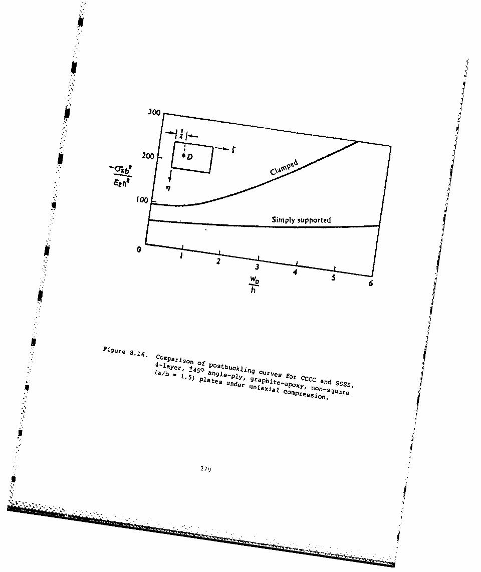
IE2100,
0/
P19ue copar Iso,
4 Ofa~er +45, P stbuklig
279

3hape has two half-waves in the x-direction, and the displacement is
therefore calculated at x = a/4, y - b/2.
Prabhakara and Kennedy [186] made a study of the postbuckling behavior
of unsymmetrically laminated, angle-ply plates loaded in shear (ax =
Gy = 0, TXy - constant). Results were obtained for glass-epoxy, boron-
epoxy and graphite-epoxy laminates having layer moduli given by Table
8.1, except that G /El = 0.0125 for graphite-epoxy. Deflection-load121
curves for various plates are shown in Figures 8.17-8.20, where wc is
the deflection at the center of the plate. In Figure 8.17 +450 angle-
ply, SSSS, square plates having two layers are considered. The effect
of number of layers (n) for graphite-epoxy plates are seen in Figure
8.18. Results from both linear and nonlinear analyses are shown. Figure
8.19 shows the influence of orientation angle, e , on the curves for two-
and four-layer, graphite-epoxy, SSSS square plates. The effect of aspect
ratio (X = a/b) for +450, four-layer, graphite-epoxy, SSSS and CCCC plates
is described by Figure 8.20.
Hui [178] considered the initial postbuckling behavior of antisymmetri-
cally laminated, SSSS, cross-ply plates subjected to uniform inplane
shear stress. He showed that the initial mode of buckling for non-square
plates is asymmetric.
An extensive experiment.'l program to study the buckling, postbuckling
and crippling (i.e., ultimate failure) of graphite-epoxy and boron-aluminum
laminated composite plates has been conducted by Spier, Klouman and Wang
[257-263]. The plates typically were uniaxially loaded, with the loaded
edges clamped, and the other two either simply supported or with one
edge simply supported and the other free (i.e., CSCS or CSCF with Ox
constant, uy - Txy - 0). These plates were also used to represent a
section of a stiffening element. An example of a load - end shortening
plot made for two CSCF, graphite-epoxy specimens of nearly identical
280
"U
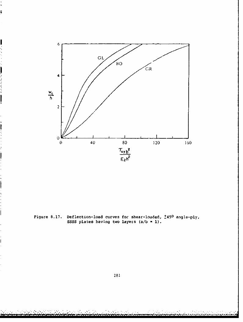
6
GL
4
Weh
2
A
0 I ]0 40 80 120 160
E2
Figure 8.17. Deflection-load curves for shear-loaded, t450 angle-ply,SSSS plates having two layers (a/b 1 1).
281

I6 0
Linear I
I I i
4o I I
Iwc IT /
0 40 80 120 Io0 200
E 2 h
Figure 8.18. Deflection-load curves for shear-loaded, _450 angle-ply,SSSS, graphite-epoxy plates (a/b - 1).
28
282

60
00
0 40 80 120 16C 2C0
I ~E 2 h2
Figure 8.19. Deflection-load curves for shear-loaded +e, angle-ply,* SSSS, graphite-epoxy plates (a/b - i).
283

6
ssss/
4,. //
2
I,
i I/
00 ,o 100 ,.o 200 250
E2ht
Figure 8.20. Deflection-load curves for shear-loaded _+45, four-layer, graphite-epoxy plates.
284

dimensions with a/b - 4.5 is shown in Figure 8.21 [260]. The sudden
drop in loading for one of the specimens was due to a jump from a two
half-wave displacement pattern to one having three half-waves. For both
graphite-epoxy and boron-aluminum composites, experimental crippling
loads were found to be considerably less than theoretically predicted
values [258,263].
A postbuckling analysis of BBSF orthotropic plates subjected to
uniaxial loading was made by Banks and Rhodes (264]. The elastically
constrained unloaded edge had rotational restraint. This type of piate
may represent the flange of a composite channel section.
An experimental ntudy of the postbuckling behavior of CCCC laminated
plates loaded in shear was carried out by Kaminski and Ashton [265,266].
Nine boron-epoxy plates having cross-ply end angle-ply orientations were
tested. A subsequent theoretical correlation with these results was
made by Shariffi [87]. Experimental results for this type of problem
were also obtained by Kobayashi, Sumihara and Kihara [2671 and compared
with theory.
Postbuckling studies of laminatod composite plates with holes have
also been carried out. Ter-Emmanuil'yan (268] examined a SYSF, orthotropic,
square plate having a central square hole. Starnes and Rouse (269) made
an experimental investigation of BCSC, graphite-epoxy plates (oy w constant,
Ox 0 Txy - 0) with circular holes. Knauss, Starnes and Henneke [2701
also considered circular holes.
A considerable amount of additional research on the postbuckling
behavior of laminated composite plates may be found in the literature
[38,173,191,271-299].
285

3" crippling loads
2-
Load(kips) "critical/
loads
1-
0 0.02 0.4 0.06 0.8End-shortening (in.)
Figure 8.21. Experimental Load-end shortening curves for uniaxially
loaded COCF graphite epoxy plates.
I 286
U

8.3. IMPERFECTION ANALYSIS
Bhattacharya [3001 made a study of symmetrically laminated, cross-
ply plates having initial imperfections subjected to uniaxial loading
(0y = constant, ax xy - 0). The plate edges were taken to be simply
supported with elastic rotational constraint (cf., Equation 3.49). The
governing equations were taken in the forms using the transverse displace-
ment (wl and the Airy stress function (f), and may be written as
A* -4+ (2A* +A* I + A*22 ax 12 66 3 y 11 ay
(3 2 w )2 _ 2w 32w + 2 3 2 w 32ý a2 w a2ý ;2w (8.-~ =ax2 3y1 + ~ 2x - ax1 =By 3y1 ax1
a w3 w
D* 3- 4 " D + wD* ) + D 34W1l1 12 r.663 y 22y
32)2 -32 32 _ a 32 a34 •7(w +) + =,(w + w) - 2 -xy 3-Zy(w + w)
where 9 is the initial transverse displacement due to the imperfection,
w is the additional transverse displacement due to the applied load, and
the Atj and Dtj are coefficients arising from a partial inversion of the
stiffness relationships (see Equation A.30). Equations (8.6) are seen
to he similar to Equations A.32 and A.33, with the following
modifications:
1. A16 A*26 - Bij a 0, to specialize to the orthotropic form for
a symmetrically laminated, cross-ply plate.
287
2. Nonlinear bending-stretching terms of the type found in Equations
8.5 are added to the right-hand-sides.
3. Additional linear terms appear on the right-hand-sides to account
for the effects of the initial imperfection.
An approximate solution to Equations 8.6 was assumed [300] in the form
of double series of the products of beam vibration eigenfurctions for
both 0 and w, and W was also assumed in this form. The Galerkin method
was used to provide numerical results.
Results were obtained for square plates composed of five layers,
having equal rotational constraints along all four edges [300]. Figures
8.22 and 8.23 show plots of the nondimensional uniaxial loading parameter2/4A2h versus wc/h, where wc is the displacement at the center, for
carbon fiber reinforced plastic (CFRP) and glass fiber reinforced plastic
(GFRP) plates, respectively. Ratios EL/ET a 7.6 and 2.0 were used for
CFRP and GFRP plates, respectively, and GLT/ET - 0.4, '"LT - 0.3 were
used for both plates. Two sets of curves are shown in each figure, corres-
ponding to zero and small (wc/h a 0.1) imperfections. For each set,
curves are drawn corresponding to various rotational stiffness parameters
K (- akr/2A2 2h 2), and kr is the rotational stiffness defined by Equation
3.49. For K - 0, the plate is SSSSI for K - =, it is CCCC.
The effects of load eccentricity were considered by Sallam and
Simitses [301]. Uniform, uniaxial, inplane stresses -ax were applied
with an eccentricity (e, measured positive in the positive z-direction)
to unsymmetrically laminated, SSSS, +450 angle ply, graphite-epoxy plates.
The same material properties used by Chia and Prabhakara [15,181] in
their postbuckling studies (see Section 8.3) were assumed (Ell - 30xlO6psi,
E22 0 0.75xl06psi, (12 - 0.375x10 psi, v 12 - 0.25). Load-deflection
curves were plotted for two- and four-layer plates having a/b - 1 or 2,
288
o,

coSA4
add
-1
.44 -1
0u L4s4) OEU
.> ..a " '~.1.4
55 iS :3
.4 40 kis 0
* i4is' I seco
* U)
hd . 4 0 J,01
T -T 1~
00 .4 0)'.g4 4'0 .
N 5 '-
289\

a
" 0
'0 0to-
0, c
\\
\ \\ \#
0 w
00
44 c
0 1f I s,.
-C =1 *1 , 11. 11 i.0L -q
0
:- 5
290
S.... .. r '" " "•| II I "" "r '"IS II Ii II I

and values of e/h varying from 0 to 0.1. These are shown in Figures
8.24 through 8.27, where wc is the transverse deflection of the center
of the plate. In Figure 8.26 the results of Chia and Prabhakara [15,181]
are also shown for e = 0.
Inasmuch as it is impossible to fabricate plates which are perfectly
flat, test specimens will always have some initial imperfection. Southvell
[40] derived a very useful formula for estimating both the critical load
and the amplitude of the imperfection from experimentally determined
data. It is extendable to laminated composite plates. Let wo be the
displacement of the plate at any point in the unloaded condition (usually
measured at the plate center or at a point of maximum anticipated displace-
ment) - that is, the imperfection amplitude. Let L be the additional
deflection at the same point resulting from the inplane load, P. It can
be shown that A/P can be linearly related to A by the equation
A o- t • A t -- (8.7)
cr
Thus if the experimental data is plotted on a graph having 6/P as ordinate
and 6 as abscissa, and a best-fit straight line is drawn through the
data, then the reciprocal of the slope of the line is Pcr, and the inter-
cept with the abscissa is -wo.
1Mandell [34] obtained load-displacement data for each of the numerous
composite plates he tested (see Tables 2.1, 5.4, 6.3) for both SSSS and
SFSF edge conditions and made Southwell plots (A/P versus 6) for each
case. A representative one for plate 201 - a graphite-epoxy, cross-ply
laminate (see Table 2.1) - is shown in Figure 8.28. Also shown in the
same figure are theoretical and experimental curves of P versus A. The
theoretical curve was obtained by the nonlinear finite element method
developed by Monforton [173], assuming no geometrical imperfection.
291
. .. E-

40
30 -
tS e/h=OS_ • .002
j o-• 20 0-06-- 0-08
10* ~ L20* 010I, _
. 0 0.5 10 1.5 20 25 3.0
WC
Figure 8.24. Load-displacement curves for eccentrically loaded, two-layer, SSSS, angle-ply plates (a/b- 1).
292
AZ

40
30
e/=
-00-(TX• 0-04E22hz 20 i0-06_2 b0-08
0-10
10
0 •I .. , . I, •0 0.5 1.0 1.5 2.0 25 3.0
Wch
Figure 8.25. Load-displacement curves for eccentrically loaded, two-layer, SSSS, angle-ply plates (a/b - 1).
293

80
60-
1741,•-;/ 0-04O-°- b 40 --/0-06
20408E22 /h 0-10
20 F1 A15,18 11
0 0 0.5 1.0 1.5 2.0 2.5 S-Wc
Figure 8.26. Load-displacement curves for eccentrically loaded,four-layer, SSSS, angle-ply plates (a/b 1 1).
2294

80
60-
- e/h=oI Lily-0-02
2-0-04
0106
20
0 - I II0 0.5 1.0 1.5 2.0 2.5 3.0
-W
Figure 8.27. Load-displacement curves for eccentrically loaded,four-layer, SSSS, angle-ply plates (a/b -2).
295
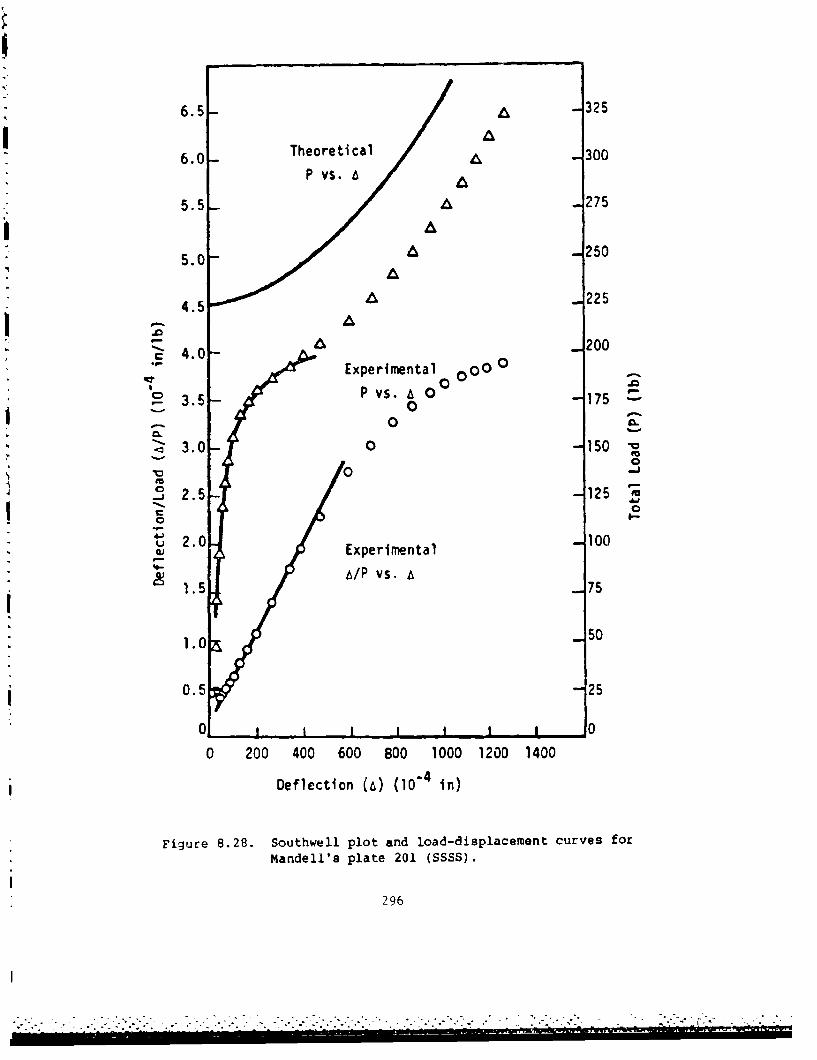
6.5- 325
6.0- Theoretical A -300P vs. 6
5.5 -- A 275
A
5.0 - 250A
4.5 A 225
4.0-200" 4Experimental 00 00
'~ Pvs. a 00S3.5 - 0 -175
,. 0 03.0 0 -150
'V0 -js. !Co._ 2 .5 -12 5 rm
0 - 0
2.0 Experimental 100
b/P vs. 71.5 _75
1.0;S 50
0.5 25
0 II
0 200 400 600 800 1000 1200 1400
Deflection (a) (10-4 in)
Figure 8.28. Southwell plot and load-displacement curves for
Mandell's plate 201 (SSSS).
296

Banks 13021 conducted postbuckling experiments on unidirectional
fiber, SSSS, orthotropic plates made of glass reinforced plastic. Large
deflection resilts and postbuckling stress distributions were obtained
for plates subjected to uniaxial loading consisting of constant in-plane
displacement. Experimental results were compared with theoretical curves
for initial imperfection amplitudes wo/h - 0 and 0.5. Banks, Harvey and
Rhodes [3031 made a study of alternative methods of expressing the inplane
boundary conditions during the moderately large deflections of uniaxially
loaded composite plates having geometric imperfections. Girn and Simitses
(304] analyzed the behavior of an SSSS anisotropic plate under the simul-
taneou3 action of inplane and transverse loads. Aalami and Chapman [3051
treated similar problems for orthotropic plates.
The effect of sign in the imperfection (i.e., positive or negative
initial curiature) upon the initial postbuckling behavior was examined
by Hui f306j. It was shown that, in certain circumstances, the initial
postbuckling behavior will be unstable (i.e., negative slope in the load-
displacement curve) rather than the customary stable form.
Meffert, Derek and Menges [307] considered the creep deformation
of SSSS laminated composite plates with initial imperfections subjected
to uniaxial compression. The creep effect was accounted for by assuming
an exponential decay of the elastic moduli with time.
297

I
CHAPTER IX. STIFFENED PLATES
Stiffened plates typically consist of plates having attached stif-
feners lying parallel to one of the edges. They are usually designed to
provide additional stiffness in the direction of primary, uniaxial loading.
Stiffeners may be of a variety of shapes, for example, I, Z, T, J, hat,
box, angle, blade or sandwich blade. Examples of four of these shapes
are seen in Figure 9.1 [3081. The stiffeners may be integrally fabricated
with a plate, or may be attached. A plate may also be stiffened by pre-
forming it into corrugations.
The buckling modes of a stiffened plate (or panel) may be quite
complex, even under relatively simple loading conditions such as
uniaxial, uni~urm compression. The presence of bending/twisting and/or
bending/stretching coupling due to laminate layup serves to complicate
the modes further. The buckling modes may be generally classified as
oveLall or local, depending upon the wave lengths of the patterns.
Williams and Stein [309] divided the classification of buckling modes of
open-section stiffened panels into local, twisting and column buckling
modes. Examples f - a repeating section of a J-stiffened plate are
shown in Figure 9.2. These modes involve either relatively independent
or strongly coupled displacements of the plate sections (skins) and
stiffening elements (webs). The "column" mode corresponds to one
dimensional buckling of each repeating section essentially independent
of the adjacent sections.
To deal with local buckling modes it is at least necessary to
subdivide the stiffened structure into a series of rectangular plates
joined to the stiffeners by proper continuity conditions. This allows
local buckling between the stiffeners. Further refinement consists of
subdividing the stiffeners as well into plate elements, which accounts
for the possibility of very localized buckling within stiffener
segments. Presum!)1y, this latter rcfincmcint alto more accurately
represents the stiffeners of the entire plate structure.
293
ý--i

HAT SANDWICH T ISLADE
Figure 9.1. Typical plate stiffening elements.
LOCALISKIN LOCAL IS KIN AND WtB TWISTING/SKIN AND [B
N ISTINd/WEB ROLLING COLUMW/WES ROLLING COLUMN
Figure 9.2. Characteristic buckling modes of J-stiffened plates.
299

However, to deal with thC Lb.ined buckling investigation described
above, complex computer programs (codes) are necessary. Listed below
are four relatively widely used codes capable of buckling analysis of
laminated composite plates with stiffeners, along with literature sourcen.
These sources may consist of publications describing the theoretical
background, user's manuals or applications to specific problems.
1. BUCLASP (Buckling of Laminated Stiffened Plates) - References
92, 93, 309-315.
2. NASTRAN (NASA Structural Analysis) - References 311, 318
3. STAGS - Refc=.?nces 308, 309, 319, 320
4. VIPASA (Vibration and Instability of Plate Assemblies, including
Shear and Anisotropy) - References 308, 309, 321-326.
These buckling analysis codes sometimes are used as parts of larger optimi-
zation procedures leading to efficient designs. Compared with metallic
stiffened plates, the number of design parameters which may be varied is
significantly greater.
The information given below is intended to give some samples of
the large amount of information which is available for the buckling of
laminated composite plates having a large variety of possible stiffeners.
The reader is referred to the individual publications for details such
an plate and stiffener detailed dimensions, laminate layups, etc.
Williams et al. [308] made a comparison of bifurcation buckling
loads obtained with various computer codes for a blade-stiffened BSSS
composite plate. The configuration analyzed consisted of a 7.6 cm square
plate with six stiffeners. Combined shear and longitudinal compression
(in the direction of the stiffeners) loading was applied. Interaction
curves for critical combinations of shear and longitudinal stress resultants
are shown in Figure 9.3. The two distinct data points were obtained by
300
Mo. rW
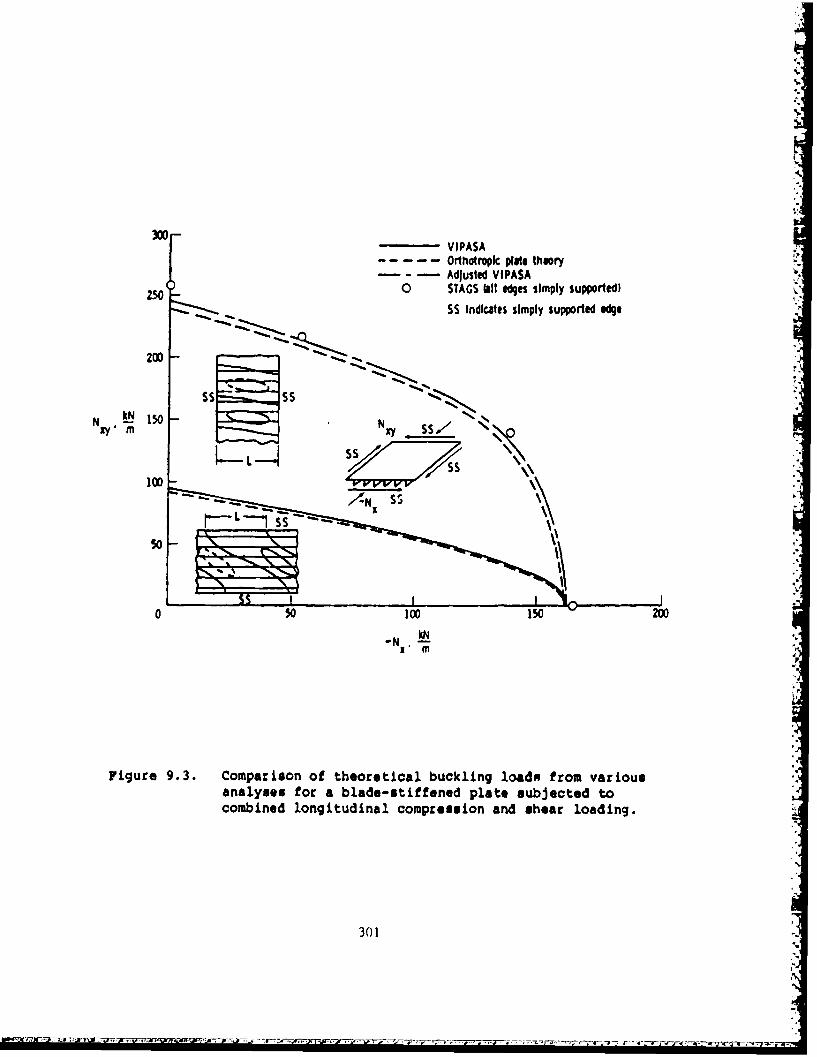
300. S'p
VIPASAOrthotropk plate theoryAdjusted VIPASA
) 0 STAGS Oill "es simply supported)
, .SS Indicates simply supported ege
200
N 50 - •, N s/"•-,
N 100 150 200N
N S
N1 m4
so-,d
0F
1," M
Figure 9.3. Comparison of theoretical buckling loadx from variousanalyses for a blade-stiffened plate subjected tocombined longitudinal compression and shear loading.
301
I.- -

an accurate, two-dimensional analysis using the STAGS code for the square
plate. The VIPASA code was also utilized. This code is one-dimensional
(i.e., two opposite edges are simply supported, exact solutions similar
in form to those described in Section 3.1 are used, and boundary conditions
may he specified only on the two edges parallel to the sLiffeners) and
is therefore more economical than STAGS. The solid (lower) curve shows
the interaction curve obtained with VIPASA with the plate having its
side edges simply supported. The dashed, lower curve was also obtained
with VIPASA, where the stiffeners were "smeared" out to represent an
orthotropic plate. The same orthotropic plate was then analyzed with
the two edges perpendicular to the stiffeners being simply suppported,
yielding the upper dashed curve. The large difference between these
curves shows the importance of correctly representing the boundary condi-
tions on the edges normal to the stiffening. Finally, an wadjusted"
VIPASA curve is depicted in Figure 9.3, which results from applying a
correction factor obtained from comparing the lower two curves to the
upper dashed one.
An interesting set of curves showing the relative structural effi-
ciency of various types of stiffened plates to withstand uniaxial buckling
loads may be seen in Figure 9.4 [308]. The mass index (W/AL), which is
the mass per unit area of stiffened plate divided by the plate length,
is plotted versus the load index (Nx/L). The PASCO 1327] code was used
to optimize the various designs. It is seen from Figure 9.4 that the
blade- and I-stiffened plates give nearly the same results and are least
efficient of the graphite-epoxy constructions. Honeycomb sandwich-blade-
stiffened plates are seen to be approximately 20 percent lighter. The
lightest design employed graphite-epoxy, hat-stiffened plates. These
latter plates weighed 60 percent less than aluminum hat-stiffened plates,
which are also included in Figure 9.4. A similar plot for blade-stiffened,
graphite-epoxy plates designed for specific ratios of combined in-plane
loads is shown in Figure 9.5. These were 76 cm square plates. The optimum
302

50 -
MASSN *1
INDEX 10
m 3 5
3
- GRAPH ITE-EPOXY
-A , . ,l I a a _a , .,a I.1 .3 .5 1 N\ 3 5 10
LOAD INDEX ('-j). MPa
Figure 9.4. Structural efficiencies of various stiffened plate con-figurations.
303
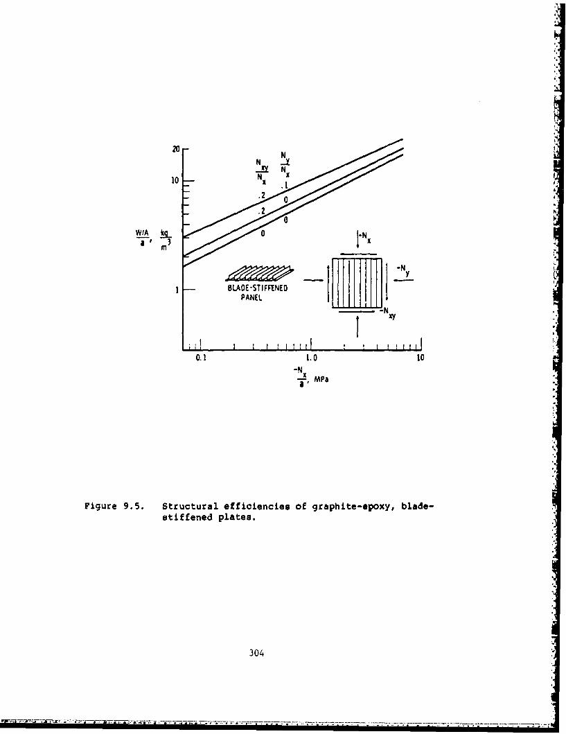
20N
10-
-A N
N ..I0 x
_- ~.20i
a ' m 3 a
m x
BL.AOE-STIFFENED IH HHPANEL I I
-- N
0.1 1.0 10"-N
xa ' MPa
"
Figure 9.5. Structural efficiencies of graphite-epoxy, blade-stiffened plates.
304
ii~' ~ T ;' ~ - .--- -. o

pZI
number of stiffeners varied with loading from 16 to lightly-loaded plates
(Nx/L 0.07 to 0.10 MPa) to 8 for heavily-loaded plates (Nx/L 5 5 to 714P&).
Wittrick and Williams .120,3261 developed a procedure for obtaining
exact solutions for the buckling of anisotropic, stiffened plates which
became known as the VIPASA computer code. This analysis permits the use
of anisotropic (but symmetrically laminated) plates and arbitrary (but
constant) components of combined (0 x& aye Txy) inplano stress. Plates
and stiffeners are made up of component plate segments, each joined together
by appropriate continuity conditions.
Recently, Wittrick and Horsington [325] set forth an accurate procedure
for analyzing the buckling of stiffened composite plates which circumvents
two of the limitations of the VIPASA codes
1. When the component plates of the structure carry shear as well
as compression, only the local buckling modes may be found.
2. Typical stiffened-plate assemblies require using 1300 to 2000
rectangular plate elements, leading to characteristic determinants
of order 8000 to 21,000.
The procedure is based upon the Ritz method and assumes displacements
for SSSS plates in the form of Equation 2.40. The resulting computer
code was called CASIOPEIA (Compression And Shear Instability of Orthotropic
Panels), and was found to yield accurate results for six stiffened panels
previously analyzed by NASA using an extremely expensive finite element
method.
Viawanathan, Soong and Millec [92,93] developed the method for
analyzing stiffened composite plates which resulted in the BUCLASP code
1310]. Correlations with buckling tests were made for hat- and angle-
stiffened, composite plates, as well as isotropic honeycomb, sandwich
plates reinforced internally with boron composite strips.
305
IMM
,-_ -

Structural efficiency studies were mAde by Williams and Miku]as
[3171 on graphite-epoxy plates having hat-stiffened and open corrugation
configurations. From the theoretical results, selected configurations
were fabricated and tested to study local and overall buckling character-istics. Experimental results were obtained for 23 plates critical in
local buckling and six critical in overall buckling and were comparedwith theoretical data obtained using the BUCLASP-2 code. Theoreticalstudies indicated potential weight savings of up to 500 for similar con-
figurations made of aluminum. Another similar set of theoretical efficiency
studies with J- and blade-stiffened, graphite-epoxy plates was made by
Williams and Stein 1309]. STAGS, BUCLASP-2 and VIPASA codes were used
in the analysis.
Agarwal and Davis [3Z8] used a structural synthesis technique to
determine optimum hat-stiffened, graphite-epoxy compression panel designs.
3uckling loads and modo shapes were calculated with the BUCLASP-2 code.
Optimization results showed a 50-percent weight savings over optimized
aluminum panels.
Bushnell [329] demonstrated the PANDA code by comparisons with the
results of Williams and Stein [3091 for a blade-stiffened composite plate.
Theoretical analysis and experimental testing of a boron-aluminum
laminate with closely spaced stiffeners was reported by Spier [3301. It
was necessary to analyze the laminate material in its inelastic range.
This design was found to yield weight savings of 34 and 42 percents over
equivalent aluminum-alloy and titanium alloy designs, respectively.
Stein and Housner [69] analyzed the shear buckling of an SSSS ortho-
tropic plate having a single central stiffener which is interrupted by a
break.
306

Mass optimization studies for uniaxially loaded, stiffened, compositeplates were made by Stein and Williams 13111. In particular, sandwich-
blade stiffeners were employed, in which the webs of the blade stiffeners
are composed of high strength composite material bonded to a low-density
core such as aluminum honeycomb. This has the effect of increasing the
critical twisting and local buckling strains without appreciably increasingthe total structural mass. An analysis method was developed which was .
compared with BUCIASP 2 and NASTRAN codes on sample problems.
A procedure for designing uniaxially stiffened plates made of com-
posite material and subjected to combined inplane buckling loads was
described by Stroud, Agranoff and Anderson [324]. The procedure is based
upon the VIPASA code. Complex, local buckling modes as well as overall
buckling were considered.
Stroud and Agranoff 13311 developed a procedure for analyzing hat-
stiffened and corrugated composite plates subjected to uniaxial (in the
direction of the stiffeners) compression and shear loadings. Numerous
curves were plotted showing the structural efficiency of such plates as
stiffener and plate thicknesses are varied.
The effect of one-dimensional (bow-type) imperfection on the inplane
load carrying capacity of graphite-epoxy, blade-stiffened plates was
studied by Stroud, Anderson and Hlennessy [332]. The VIPASA code was
modified to permit the imperfection analysis. The effects of bow-type
Imperfections are also discussod in 1308].
Turvey and Wittrick [3331 made comparisons of the buckling stresses
of CFRP composite plates having open (blade), closed (box) and Z-type
stiffeners with those of corresponding aluminum plates. Comparisons for
troughed (corrugated) plates were also made.
J(J2

Chiu (334] considered the buckling of uniaxially loaded CFCF laminated
composite plates having attached stiffeners composed of both metal and
composite portions. Theoretical and experimental results were compared.
Because the buckling loads predicted theoretically were much higher than
test results, a simplified method to accommodate plastic behavior of the
metal beyond the yield point was developed.
Experimental and theoretical studies of the shear buckling of a
graphite-epoxy plate having J-stiffeners in its interior and along its
edges were made by Davis [335]. Theoretical calculations were made with
the VIPASA code.
Gunnink, Vogelsang and Schijve (336,337] studied the buckling of
orthotropic plates made of ARALL (Aramide Reinforced Aluminum Laminates)
having Z-stiffeners.
Hui and Hansen [338] took up the buckling of square, antisymmetric,
angle-ply plates with stiffeners attached to unloaded edges, while the
loaded edges are simply supported.
Buckling and postbuckling static tests of shear-loaded graphite-
epoxy plates were conducted by Ostrom [3391. Integral J-stiffeners were
located internally, parallel to the plate edges. The postbuckling behavior
of multibay composite shear webs was explored by Agarwal [272]. Hat and
I stiffeners were added to graphite-epoxy plates to form the webs. Both
theoretical and experimental results were obtained. Composite shear
webs were found to have significant postbuckling strength. Several other
postbuckling studies for stiffened composite plates have been reported
[191,260,340-3461.
Symmetrically laminated SSSF plates having integral blade and Y-
stiffeners were considered by Lackman and Ault [99]. Weight optimization
studies were condue-fct1 for ,un1axia] loadine.
308
Kicher and Martin (see [191], pp. 206-209, and [190]) investigated
the buckling and postbuckling of SSSS symmetrically laminated plates
with circular holes, with or without stiffeners around the hole periphery.
Both theoretical and experimental data were obtained.
The vast majority of references in this chapter dealing with stiffened,
orthotropic or anisotropic plates are aimed at aerospace structures.
One also finds buckling analysis of such configurations found for bridge
decks [347] and ships [348].
Other references taking up the buckling of composite plates with
stiffeners are 134,349-367].
3
30
I
I4.
!p

CHAPTER X. BUCKLING OF CYLINDRICAL SHELL PANELS
This chapter is devoted to the bifurcation buckling of laminated
composite panels having curvature. Such configurations are properly
called "shells" (although one sees the term "curved plate" sometimes
used in the non-academic literature). Indeed, a plate may be considered
to be a special case of a shell having zero curvature.
General shells are described by three components of curvature along
every point giving rise to a wide variety of shell configurations (e.g.,
circular cylindrical, noncircular cylindrical, conical, spherical, ellip-
soidal, hyperbolic paraboloidal). The present work will limit itself to
circular cylindrical shells which is, by far, the case most frequently
studied in the literature (more has been written for these shedls than
all other types together), and which is particularly important for lami-
nated composites.
Moreover, the present work will bc limited to shell panels - that
is, open rather than closed cylindrical shells. Such a panel is depicted
in Figure 10.1. The shell has radius R, axial length a, projected width
b, rise c and thickness h. A shell, like a plate, is mathematically a
two dimensional configuration, its behavior being characterized completely
by its middle surface. Thus, two coordinates attached to the middle
surface described its deflected (e.g., buckled) shape. For the circular
cylindrical shell these are the axial (or longitudinal) coordinate (x)
and the circumferential coordinate (a), as shown in Figure 10.1. For
the latter, the arc length y - RO is sometimes substituted.
Isotropic shells are governed by tcinth order sets of differential
equations which describe the configuration displaced in an equilibrium
state. Laminated composite shells also yield eighth order sets of equations,
although they are algebraically somewhat more complicated due to the
310

Figure 10.1. Circular cylindrical shell panel.
PII

relatively large number of stiffness coefficients involved (for an iso-
tropic shell there are only two). Thus, four boundary conditions must
be specified along each edge to completely define a problem.
One set of boundary conditions deserves special mention. This is
the shear diaphragm (also called "simply supported" or "freely supported"
in the literature). For the unsymmetrically laminated plate they were
called s2 conditions (see Equation 6.2). For such conditions on all
four edges and uniform axial and/or circumferential loading, an exact
solution for buckling of orthotropic (i.e., cross-ply or unidirectional
plies parallel to the edges) is available. This is given by Equations
6.3, where now u and v are tangential displacements in the x and y (or
0) directions, respectively, and w is the transverse (or normal) displace-
ment component. Interestingly enough, exact solutions are also theoreti-
cally possible when only two opposite edges (either straight or curved
ones) have shear diaphragm conditions (cf., pp. 83-85, [1681), but the
algebraic complexity is so overwhelming as to make a properly convergent
approximate solution more desirable. Furthermore, the case when the two
straight edges have shear diaphragm supports (and included angle o =-r/n
radians, with n an integer) is identical to that of a closed circular
cylindrical shell buckling into a mode shape having two or more circumfer-
ential half-waves.
No attempt will be made in this work to present a derivation of
shell buckling equations for laminated composites. The procedure is
quite intricate and can lead to various final forms of equations depending
upon assumptions which must be made at various stages of the process.
For a careful exposition of the steps and assumptions involved in deriving
shell vibration equations, the reader is referred to Chapter I of Reference
[168]. Buckling equations (or shell vibration equations with initial stresses
present) are even more complicated, for they require consideration of
infinitesimal displacements from a previous, loaded equilibrium state.
312
l. . .... ........ -.. . .

10.1. CYLINDRICAL SHELL BUCKLING BQUATIONS
The equations governing the equilibrium, buckling or vibrat on of
a homogeneous, isotropic, thin plate are uniformly agreed upon by essen-
tially all academicians. For laminated, composite plates essential agree-
ment is also found, even in the case of unsymmetrical laminates where
bending-stretching coupling exists. However, the situation is different
for shells. Equations for the bifurcation buckling of a circular cylin-
drical shell may be written in matrix form as
[L] {u} = {0} (10.1)
where !u) is the vector consisting of the three displacement components,
and [L] is a matrix differential operator containing two parts; i.e.
[L"] [LS] - [Li] (10.2)
[L] represents the stiffness of the shell, whereas (Lij Lesults from
the initial stresses (prior to buckling). 1LO] can take many forms,
depending upon assumptions made in deriving thin shell theories, even
for an isotropic shell (cf. [1681, pp. 32-34), and the results for buckling
loads may differ significantly depending upon the theory used. DiGiovanni
and Dugundji [368] (see also [168], pp. 188-189) developed [L1] matrices
for anisotropic, circular cylindrical shells for several of the most
widely used theories. It is also found that the initial stress matrices
fLi] will differ, depending upon the assumptions made in deriving the
various theories (cf. [168], pp. 232-234).
Viswanathan, Tamekuni and Baker [369,370] developed a theory for
the buckling of laminated composite, cylindrical shells. In examining
their equations of equilibrium for the buckled state, it is found that
the stiffness matrix may be expressed as the sum of two parts, i.e.,
313

[LS] * [LS Ij + [LO ] (10.3)
where [L8 1] is a matrix operator having elements defined in the Appendix
by Equations A.21, and the elements of[Ls 2 ]are
S2 0L lO11
2 4D §32 / 4D2 6 a2 2 32L','2 / (--6 R (X6B26 +R )/ 30~y (2 22+ ay
32 2 a2 aL 2B 4B - +2 2 233 2B12 + 4B26 xy+ 222 + +
"s2 s2 a322L2 L 21 2,B" B12 + 2Ba -3y B26 =5 (10.4)
Ls2 L s2 3,-A a a13 31 12 TX 26 y-
s2 = L 2 6 + A 22 632 3 32 = 2 6 + ) x + + ax,
23 32
(D 1 2 4 x, y 26 3x22•
It is observed that Equation 10.3 yields the differential operator [L 1 ]J
for unsymnetrically laminated composite plates as the curvature (l/R)
approaches zero. Elements of the initial stream matrix operator were
found to be [370]1
Li -N
'2
1 32 N pLi -N =3 + 4- t
22 xX Rx
21 92 32 32Li 1 + 2Nx + N
33 X =ax 2 xy axay Ny 5y'
314
W.A
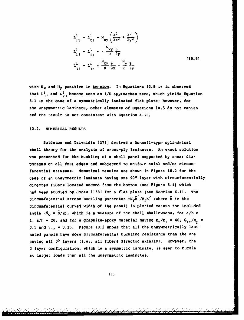
Li i N a2 +M
12 21 xy\37 3y/N
Li L i xy 313 S1 R 3y
± N N (10.5)
Li Li xy- +33 32 R Tx R ay
with Nx and fly positive in tension. In Equations 10.5 it is observedthat Li and Li become zero as 1/R approaches zero, which yields Equation
13 235.1 in the case of a symmetrically laminated flat plate; however, for
the unsymmetric laminate, other elements of Equations 10.5 do not vanish
and the result is not consistent with Equation A.20.
10.2. NUMERICAL RESULTS
Soldatos and Tzivnidis [3711 derived a Donnell-type cylindrical
shell theory for the analysis of cross-ply laminates. An exact solution
was presented for the buckling of a shell panel supported by shear dia-
phragms on all four edges and subjected to unifo.r axial and/or circum-
ferential stresses. Numerical results are shown in Figure 10.2 for the
case of an unsymmetric laminate having one 900 layer with circumferentially
directed fibers located second from the bottom (see Figure 6.4) which
had been studied by Jones 11581 for a flat plate (see Section 6.1). The
circumferential stress buckling parameter -Nyb2/E 2 h 2 (where b is the
circumferential curved width of the panel) is plotted versus the included
angle ( 0o - b/R), which is a measure of the shell shallowness, for a/b -
1, a/h - 20, and for a graphite-epoxy material having E2 /E! * 40, G12 /E 2
0.5 and v12 - 0.25. Figure 10.2 shows that all the unsymmetrically lami-
nated panels have more circumferential buckling resistance than the one
having all 00 layers (i.e., all fibers directod axially). However, the
3 layer configuration, which is a symmetric laminate, is seen to buckle
at larger loads than all the unsymmetric laminates.
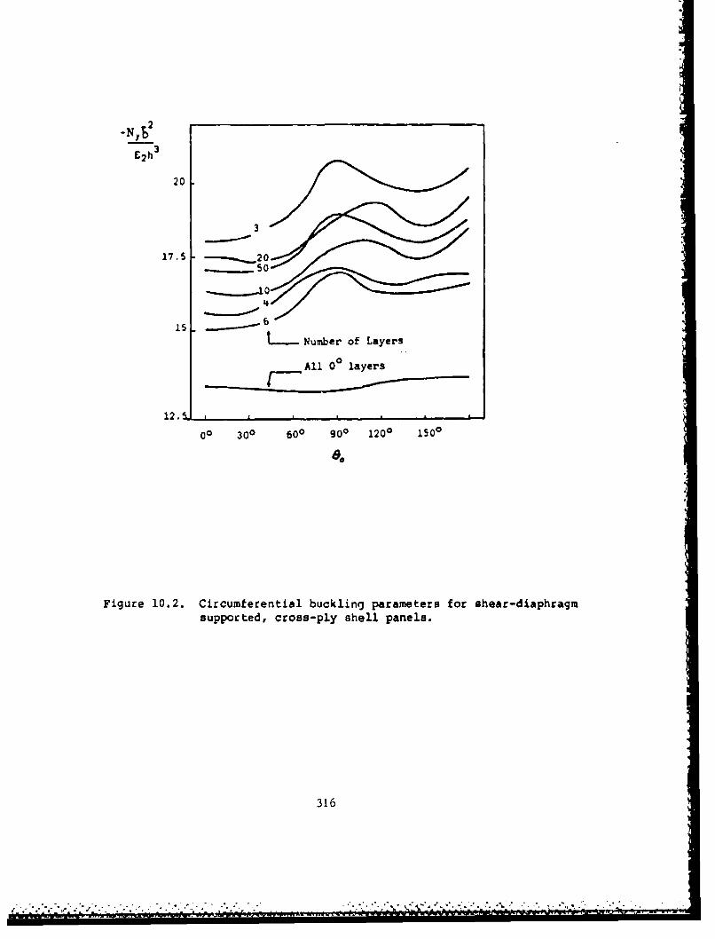
-NYS
E2 h 3
20
3
17.5 ~ ~ 1
4
156
tMumber of Layers
All 0 0 layers
12.5 _ _ _ _ _ _ _ _ _ _ _ _ _ _ _ _ _ _ _ _ _ _ _ _
00 300 600 g00 1200 1500
a,
Figure 10.2. Circumferential buckling parameters for shear-diaphragmsupported, cross-ply shell panels.
316
. -

Viswanathan, Tamekuni and Baker [369,370] conducted extensive para-metric studies of the influences of curvature and inplane boundary condi-
tions on the buckling of symmetrically laminated, boron/epoxy shell panels
of infinite length. The panels contained eight layers (0/900/÷450/-45Os,
each layer being 0.014 cm thick, yielding a total thickness of 0.112 cm.
Composite material properties used were: E 20.7xl10 N/02 (30.Oxl06psi),E22 0 1.86x10' 0 N/m2 (2.7xlO6psi), G, - 0.48x10 N/rn (0.7xl0 psi) andV12 a0.21. All panels were 25.4 cm (10 in) in projected planform width,
b (see Figure 10.3). Six possible combinations of inplane boundary condi-tions along the straight edges were investigated (Figure 10.3). The
out-of-plane boundary conditions were clamped (w a Dw/ax - 0). The curva-ture parameter 62/Rh was varied between 1 and 1000, where b is the cir-
cumferential acc length.
Critical values of the axial stress resultant Nx are shown in Figure10.4 13701. Numbers designating the curves correspond to the inplane
boundary condition code listed in Figure 10.3. Variation of circumferential
buckling stress resultant NY with X/6, where A is tho axial half-wave
length of the buckle pattern is depicted in Figture 10.5 for b2/Rh - 300.
Abrupt changes in the curves occur where the buckling mode shape changes
drastically. Results from using a Donnell-type shell theory deviate
significantly from the more accurate analysis for large X/b. Figure10.6 shows a more abrupt change in the vicinity of A/& - 100 for a shellpanel having boundary condition type 4 and 6 /Rh a 1. Variation of NYwith b2 /Rh for various edge conditions is seen in Figure 10.7. Changes
in shear stress resultant Nxy with A/b are depicted in Figure 10.8 for-2b2/Rh 0 700 with boundary condition type 3. Curves for all six types of
boundary conditions listed in Figure 10.3 are shown in Figure 10.9, where
critical Nxy is plotted versus b2 /Rh. Curves similar to Figures 10.4,10.7 and 10.9 are seen for combined stresses, -Nx - Nxy (Figure 10.10),
-Ny - Nxy (Figure 10.11), Nx - NY (Figure 10.12) and Nx - Ny - -Nxy (Figure
10.13). Tabulated values of the critical buckling loads and the associated
317

i26b.4 em
pA*1,, Q/*W.44/-45)
material:bbotonl/Poly
Thiskneo of oOch 1aG nai 0.)14..
Total t hiknwss h- 0.1112
gowndory Inploanebowlrycnd itions11-0CondltlO1 gngpano boodery condltions on kalmpvd edge A oa oIp"d edge a
cod&
J v~veOmet*#
p - - _- _
2 .-.weO e~ ev
3 ..s.o -•,OI24 ON 0 a
4 Uv'N.,'o °U.,..
Figure 10.3. Boundary conditions along straight edges of shell panelsanalyzed by Viswanathan, Tamekuni and Baker.
318

I\
Inswofl bound Ory o0d0tIon PI, Ad 2
'5'+
I3!3
" * A A A A • -
I Figure 10.4. Variation of NX with curvature parameter for shellpanels of Figure 10.3.
319

34 ,
36
26
74
14
12IpasbudayCAilr
10
Figure 10.5. Variation of NYwith axial half-wave length (A) for61/Rh 300.
32)0

0,. 103
'I
12
InplOns boundory tCfidItIon 4
I I f l il| l I l i - I I l I I I Il tll| _1 I I tlllf ll I I . /I I I [
Figure 10.6. Variation of NY with axial wave-length (A) for b 2/Rh - 1.
321

I0-3
IAAAI A ,,,.I.Ion -21"~r 10~~f~~ Won?\ h .
Figure 10.7. Variation. of Nywith curvature parameter.
322

'act to)sl.10D
teoo
140 I oobudrf¢nii• m•' G'
.toZ
I * iI~aI I Iepil . i ugmam p i~ii* 0 Il tuc 1
Figure 10.8. Variation of Nxy with axial half-wave length (X) for2/Rh = 700.
323

Iqlowa" bowrilery COnditlion
II
loBI-
3---.-- 4ý a
I 4
.1 I !0 72 10 tOGO C
Id
iff
Figure 10.9. Variation of Nxy with curvature parameter.
324
_"f

Sn0iG1 bo@ doery coAdhIloP -N
S--------
IO'1 ,• Nj•,• .h. 112 •
'Os%
LA
t.m I •I *A~dI I I I *ita~t I I L I 1111J 1 I * I * 1 i111 ' n i I i l
.00 M0 Ic IOw
Figure 10.10. Combined stress buckling parameters (-Nx -xy).
325
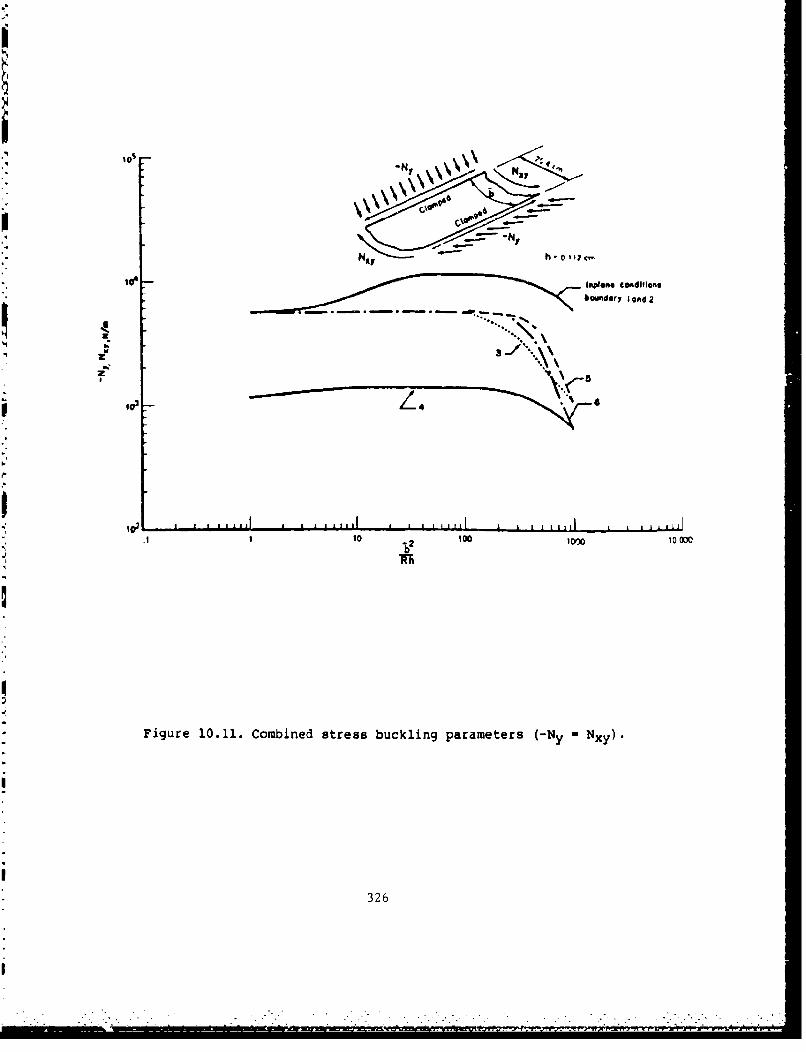
it "=' h- ell?
ift#oa*t CoAdIfIOF,
bosmdery a~nd2
z
3020600 0WFigure 10.11. Combined stress buckling parameters (-NY Nx)
326
I :- , - : ". _

-NY h. o 0i7cm MOOR S l o, ro y conditio•s
'0 -
$
1 20 t o oK I ~ tO 0 0 0
Figure 10.12. Combined stress buckling parameter~s INx - y).
327
I *0....

I
A,
.' II I I iltiJi _. a I I il llii l I I lli 11 I I I lI litl _ _ I tI tll lI, to tgoo•oo•
F~gure 10.13. Combined It~rila buckli~ng pa Cra~ttelr l (NX * *• X •)
328
loop

values of A/b are also given in 13701 corresponding to Figures 10.4-
10.13.
In addition to the results described above, data are also plotted
in 13701 for other laminated composite shell panels of boron-epoxy, boron-
aluminum, high modulus graphite-epoxy and borsic-aluminum materials.
The analysis methods leading to BUCLASP-3, a computer code capable of
determining buckling loads for heated, stiffened, laminated composite
shell panels was described by Viswanathan and Tamekuni [314]. Biaxially
loaded, stiffened composite shell panels also received particular attention
[315,316,372].
Becker, Palazotto and Khot [373-375] conducted a theoretical and
experimental investigation of the buckling of a set of 8-ply laminated,
graphite-epoxy, cylindrical shell panels subjected to axial compressive
loading. The curved edges were clamped and the straight edges had five
types of boundary conditions, varying between completely clamped and
completely free. Three types of symmetric ply layups were used, as des-
cribed in Table 10.1. Material properties were determined experimentally
to be; E a 20.5xl0 6psi, E * 1.3x10⁶psi, G, a 0.75xlO6psi, V " 0.335.1 2 -2 12
Numerical results for bifurcation buckling were obtained by the STAGS-C
computer code, which utilizes two-dimensional finite-difference approxima-
tions of the total potential energy of the system for a/b = 1.5, 1 and
0.75, with a/R = 1 and R/h - 300. Values for -Nxa 2/EIh3 are listed inTable 10.1. Two types of clamped (Cl and C4) and simply supported (Sl
and S4) boundary conditions were employed on the straight edges, as defined
by Equations (6.2) and (6.10). As expected, the buckling loads in Table
10.1 for the Cl and S1 straight edge support conditions are larger than
those for the C4 and S4 conditions, respectively. One configuration
(12x16, (+45)2,) shows contrary data, which was attributed to be the
result of an incorrect bifurcation analysis 13741. Experimental results
fcr six of the configurations are presented in Chapter 11. From the
329

Table 10.1. Axial buckling load parameters -Nxa 2 /E h3
for a series of 8-ply shell panels.
Size, Straight Ply layupa x b edge (±45) (90,±45,0) (90,0)(in) B.C. 2S s 2s
Cl 68.8 58.2 50.3C4 44.1 46.0 36.7
12x8 Sl 66.0 57.5 49.2S4 40.8 45.7 32.0
free 12.0 14.5 10.7
Cl 54.5 52.6 40.3C4 43.0 45.6 34.4
12x12 S1 52.3 52.1 39.6S4 42.9 45.4 33.3
free 12.8 15.1 11.4
Cl 40.7 49.5 36.0C4 42.6 45.2 33.5
12x16 Sl 38.9 49.3 35.8S4 42.5 45.2 33.1
free 12.8 15.2 11.5
330
I

entire study it was concluded that 1374] the boundary conditions had the
greatest influence on the buckling load, followed by the aspect ratio
and, finally, the ply orientation.
Davenport and Bert [205-2071 investigated the buckling of sandwich
shell panels subjected to combined shear and axial compressive loads.
Both facing and core materials were assumed to be orthotropic. CCCC and
,3SS edge conditions were treated. The problems were solved by the Galerkin
method using assumed displacements which were the sums of products of
trigonometric functions.
Wilkens [3761 provided extensive experimental results for the buckling
of graphite-epoxy laminated composite shell panels having clamped (loaded)
circular edges and either clamped or simply supported straight edges.
Experimental buckling loads were determined by the Moire grid shadow and
Southwell methods. Theoretical values were also calculated using the
Ritz method 1377 1. Tests were conducted on 72 panels having R - 12 in,
a - 12 in, b - R0o - 8 in and 100 f- R/h ý 400. Although thickness devia-
tions were measured, which in some panels were considerable, no attempt
was made to measure imperfections due to deviation from cylindrical curvature.
Experimentally determined buckling loads were typically found to be consider-
ably less ( "20-50 percent) than the theoretical values.
-- '
Extensive data was also given by Pogg [321 for the buckling of
"graphite-epoxy shear panels loaded in axial compression or shear. Sandwich
panels were also investigated.
Zhang and Matthews 1188,3781 derived a set of governing equations
for buckling of arbitrarily laminated cylindrical shells expressed in
terms of the transverse displacement (w) and an Airy stress function
(0). Problems for ahell panels having all edges clamped and subjected
4-=•. to axial and/or shrpar loads were solved by means of the Galerkin method,
-.,
"!. .-. .-... - -. -. . . ..-. _ • _ 4V4•.., i, -- • r.,y .- • r ,• •.

using products of beam vibration eigenfunctions to represent both w and
-. The importance of using double precision in the calculation of the
beam functions was demonstrated. Extensive numerical results were obtained
for panels having a/b - 1, a/R - 0.5 and R/h = 200, where b R0O is the
circumferential arc length. The materials typically used in the parameter
study was boron-epoxy, with EI/E 2 1 10, G1 2 /E 2 - 0.3 and v12 a 0.3.
Numerical results for the axial buckling load of angle-ply panels
having 20 plies are shown in Figure 10.14. Two types of layups are con-
I sidered: (1) alternate plies (±O) and (2) unidirectional plies (+6).
Variation of -Nxb 2 /E 2 h3 with the layup angle 0 (measured from the x-
axis) is shown for both the shell panel and a flat plate (R v ®). For
the alternating angle-ply layup the shell shows maximum buckling loads
at two values of 0, approximately 200 and 700. The change in buckling
load with decreasing curvature for various numbers of plies is depicted
in Figure 10.15. The effect of fiber orientation upon shear buckling
loads is seen in Figure 10.16 for shell panels having unidirectional
layups (+0). Curves for both positive and negatively directed shear
loads are shown for three curvatures. Change in sign for the shear load
may also be interpreted as change from +0 to -0 in fiber orientation for
a given shear load. It is observed in Figure 10.15 that this change of
sign causes considerable change in shear buckling loads. It was further
found 1188] that this effect was less pronounced for symmetric (+0) angle-
ply layups, uand iL de4Leabed at Lhe number of plies was increased. For
antisymmetrical layups the direction of shear loading was found to have
essentially no influence on the critical load.
Figures 10.17-10.19 are interaction curves showing critical combina-
tions of axial and shear loads which cause buckling [3-30]. In each
case Nx is plotted versus Nxy, where Nx is the ratio of the critical
compressive axial load with shear to that without shear and Nxy is the
ratio of the critical shear load with compression to that without compression.
332
mI
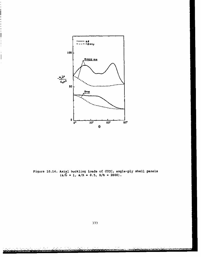
only
100
Eazh3 .e
5060 .1. ....... -....
00 30O' Sl0ge
Figure 10.14. Axial buckling loads of CCCC, angle-ply shell panels(a/b - 1, a/R- 0.5, R/h - 2000).
333
. -. -- 4 - #v _ .

-curved panelorthotroptc solutlon - flat plate
100 -four aers 45
_N.;2 two Ia ers (+45 45)
£Zh3
50
a -. .=
0 go0 1000 1500 2000VR(mm)
Figure 10.15. Variation of axial buckling load with decreasingcurvature (CCCC, a/b - 1, a/h * 2000, a - 250 mm).
334
lw,-W 4.rWVW

-- Negative shear. - - Positive shear
ISO
100Exh2
505
50
0 30 50 go0*
Figure 10.16. Effect of shear loadikag direction upon the criticalbuckling loads of CCC shells having unidirectionallayupS (a/b 1 , &/R *0.5, R/h -2000).
~335
- - -q

Curves for both positive and negative shear are drawn. In Figure 10.17
the curvature is varied for a shell panel with unidirectional fibers
(0 = +450). Figure 10.18 examines the effects of various types of layups
(R/h z 2000). Figure 10.19 shows curves for three types of materials -
graphite-epoxy and glass-epoxy, in addition to the previous boron-epoxy
- for 0 - +450 unidirectional layups (!/h = 2000). Elastic constants
for the materials are listed in Table 10.2.
Figures 10.20-10.23 show the results of a study made to compare
the effects of clamped versus shear diaphragm (simply supported) edge
conditions f1881. Figure 10.20 is for the unidirectional layup (compare
with Figure 10.14) with varying fiber orientation. In Figure 10.21 the
number of layers (n) in symmetric and antisymmetric angle-ply layups
(. 450) is varied. The effects of varying the aspect ratio (a/b) in the
case of positive shear loading are seen in Figure 10.22. Finally, Figure
10.23 shows interaction curves for shell panels having two opposite edges
clamped and the other two simply supported, loaded in combined axial
compression and shear. These panels have +450 symmetric angle-ply layups
with four layers, and the data may be compared with that for the CCCC
case shown previously in Figure 10.18.
Baharlou [1011 considered the buckling of a two-layer, cross-ply,
SSSS shell panel subjected to axial compression and showed that, even
for relatively deep panels (b/R = 0.5) the critical load is virtually
unaffected by the stacking sequence (i.e., whether the ply with circumfer-
ential fibers is outer or inner).
Knitsson [3791 tested an integrally stiffened, graphite-epoxy shell
panel with the ends clamped and the sides supported. Good correlation
was found between the theoretical and experimental buckling load.
Durlofsky and Mayers i210,211] developed a theory for the buckling
of generally laminated, cylindrical shell panels including the effects
330C
----- - ----

- Negative shear.8 .... Positive Shear
1.6
1 .4
1.2
i 1.0t•x
0.6
0.4 .
0.2
0 0.2 0.4 06 0.8 .0
Nxy
Figure 10.17. Compression-shear interaction curves for CCCC, unidirec-tionally laminated (Q - 450), shell panels with variouscurvatures (a/bE 1).
3 37I-

Negative sheorS.8 .. .Poitive shear
1 .6 ,
one layer ( 450four layers ( *450)
1 .4
1 .0
0.e
0.6
0.4
0.2
0 0.2 0.4 0.6 0.8 1.0
Nxy
Figure 10.18. Compression-shear interaction curves for CCCC shellpanels with various layups (a/b 1, a/R = 0.5,R/h = 2000).
338

Neootve houlr
S.8 .. . Positive shear
1 .6
1.4
1.0
0.8 "" *"
0 .•6 cot bon/e oAoooooooo x
0.6
0 o. 0.4 0.6 0.8 1.0
Nxy
Figure 10.19. Compression-shear interaction curves for CCCC, unidirec-tionally laminated (e - 4503), shell panels of variousmaterials (a/6 1 , a/R - 0.5, R/h -2000).
3",9

Table 10.2. Elastic constants used by Zhang and Matthews.
Moduli (GN/m2)
Material E E E (GVlE 1 2 12
Boron-epoxy 206.9 20.7 5.2 0.3Graphite-epoxy 206.9 5.2 2.6 2.6Glass-epoxy 53.8 17.9 8.9 8.9
so , all edges clampedS~straight edges s-s
S~curved edges clomped '
60
40
20 curved edges s-sstraight edges clamped
a% ll edges s-s
0 300 60' 90
0
Figure 10.20. Comparison of uni;!xial buckling loads for clamped andsimply supported edge conditions (a/b - 1, a/R - 0.5,R/h - 2000).
3i40

:00 00symmetrfc loyer$--. 0tlsymnmetri¢ layelrs
a- .- e.-artor*ltropic solutilon
ail edges Clamped
So al edges 6-6
I
II
5 to1 Isi 20
n
Figure 10.21. Comparison of uniaxial buckling loads with varyingnumber of layers in angle-ply (!451) iayJps (a/b , 1,a/R - 0.5, R/h - 2000).
ISO - Four layers (1450)6S.... - One loyer (4 5 0)
100 oll edges Clamped
0 0.5 3.0 3.5 2.0
Figure 10,22. ,comparison of positive chear buckling loads with aspectratio for various shial panels (a/R r 0.5, R/h • 2000).
5' I
mi

- Negative shear
13 .... PosLiive sheor
straoght ed"s clagmedcurved odgox s-s1.41.4 straight edges s-s
curved edges cww4d
1.2
1.0
0.6 *
0.6
.. %
% %
% . % %
0 0.2 0.4 0.6 0.0 1.0
Nxy
rlgure 10.23,. Compresulon-shear intecrction curies for BCSC shell
panels having symmetric angle-ply (±450) layupu (a/b 6 1,& / R , 0 .5 , R/ h --0 00 ) .
J/ *• ;

of shear deformation. Application was made to an SSSS panel carrying
axial compression. It was shown that the shear deformation effects may
be significant.
Buckling as a special case of a free vibration analysis (when the
frequency becomes zero) was the approach used by Fortier [380] and by
Sinha and Rath 1381]. The former used the Ritz method with assumed
solutions in the form of products of beam vibration eigenfunctions to
analyze symmetrically laminated, cross ply and +450 angle ply shell
panels having four types of edge conditions, subjected to axial
compression. The latter treated SSSS, arbitrarily laminated, cross-ply
parnels for which an exact solution is possible.
343

CHAPTER XI. POSTBUCKLING AND IMPERFECTIONS IN SHELL PANELS
Relatively few references are available which treat the postbuckling
behavior of cylindrical shell panels, or which consider the effects of
geometric imperfections (i.e., deviations from the perfect cylindrical
surface) upon the load-deflection characteristics. Postbuckling studies
for shell panels are particularly important because, unlike plates, theirload-carrying capacities may decrease after the bifurcation buckling
ON
loads are reached. Furthermore, the presence of small imperfections may
cause large displacements to occur at loads well below the buckling loads.
11.1. POSTBUCKLING STUDIES
Zhang and Matthews [378,382] developed a set of coupled equilibrium
and compatibility equations governing the postbuckling benavior of arbi-
trarily laminated, cylindrical shell panels. These nonlinear equations
were solved by the Galerkin procedure for the case of SSSS panels subjected
to axial compression. Normal displacements were assumea as the sum of
the products of sine functions and the squares of sine functions, whereas
the Airy stress function was taken as a sum of products of vibrating
beam eigenfunctions. Applying the Galerkin method led to an infinite
set of algebraic cubic equations. A truncated set of these nonlinear
equations was solved by an iterative scheme.
Parameter studies were made for boron-epoxy panels (E /E. 10,
G /E 0.3, v 0.3) having either unidirectional plies with fibers12 2 12
oriented at 450 with the longitudinal axis, or angle-ply (+450) layups
"(382). The panels were subjected to axial compression. a/b was set at
unity (b = R 0O is the circumferential width), and the circumferential
width to thickness ratio (b/h) was set at 100. Figure 11.1 depicts
the postbuckling behavior of a shell panel having a curvature parameter
b2 /Rh = 25 compared with that of a corresponding flat plate for panels
--44
- -. . - r w rr

,4
iF
Plots
X30*1 4
Shell
w7"h
Pigure 11.1. Poatbuckling load-deflection curves for 8858 boron-epoxy panels with unidiractional fibers at e * 450.
345
345
)

Infinite 4i ayers I layer 4 layers - -layers_ 1 4S,24s) 14,S) 14•S)$ "••
Ezjh3 30 -20 '"
0 2 layers
1 S 7-ss
h
Figure 11.2. Postbuckling load-deflection curves for BSSS boron-epoxy shell panels with various ply layups.
I.
34 (°

I°
Barbon/epoxy
60
Gloss/epoxy
1 2 3 4 6 7
h
Figure 11.3. Postbuckling load-defection curves for SSSS shellpanels of various materials with a symmetric four-layer, angle-ply layup.
347
".• _ t .* - , , .. _ ' .' - - . - - - • • . $ A' • _ '_ ' , . '_ ' - • . °. • ," , - -- " . _ • . _ ' L • ' " ' '

having unidirectional fibers. The nondimensional load -Nxb 2 /E 2h3 isshown plotted versus the ratio of the center deflection to the thickness
(wc/h). As for isotropic panels, the presence of curvature is seen to
increase the bifurcation buckling load, as shown on the ordinate axis.
However, unlike the plate, which has a monotonically increasing load-
deflection curve in the postbuckling region, the shell panel exhibits an
initial drop in load before increasing. In a physical situation, a jump
across may occur before the bifurcation load is reached. The cusps occur-
ring in the curves of Figure 11.1 correspond to abrupt changes in the
postbuckled mode shapes as one follows an equilibrium path of minimum
loading.
Figure 11.2 shows the influence of ply layup on the postbuckling
behavior of the shell panel. Two of the curves are for antisynmetrical,
angle-ply laminates having two and four layers [3821. One is for a sym-
metrical, angle-ply laminate with four layers. The two-layer, antisymmetri-
cal layup is seen to yield not only the lowest buckling load, but also
the lowest postbuckling equilibrium curve. Figure 11.3 describes post-
buckling curves for symmetrically laminated, four ply shell panels made
of three sets of materials - carbon-epoxy, boron-epoxy and glass-epoxy.
Elastic constants used are given in Table 10.2. Additional results are
given in [382] for the variations in membrane force and bending nmoent
at selected points on a boron-epoxy shell panel.
Tests were reported by Becker, Palazotto and Khot [373-3751 for a
set of shell panels which were clamped along their curved edges and had
either S4 or free straight edge boundary conditions. Results for axial
compressive buckling loads were obtained for six configurations as
indicated in Table 11.1 (experimental values listed are the average of
the results found using two specimens for each configuration). The
shell panels are described further in Section 10.2. Table 11.1 shows
that the theoretical, bifurcation buckling loads obtained were from 23
348
-. - -',-" ,"-..." ..-" .." . ..."."- ." :. ".-." . ".'. '.-... " • ........ . ._'_ -... .'.','v .'-'.

Table 11.1. Comparison of theoretical and experimental values of-Nxa 2 /E h 3 for a series of 8-ply shell panels.
1
Panel Ply layupdescrip- Type of result (±45) (90,±45,O) ( 9 0 ,0)2S
t ion2SSS
12x12 Bifurcation analysis 42.9 45.4 33.3
S4 Nonlinear collapse 325 32.5 29.5straight analysis3252. 9j
edges
Experimental 28.5 25.0 24.5
12x16 Bifurcation analysis 12.8 15.2 11.5
freestraight Experimental 9.8 11.3 8.3
edges
349

10. T''o 16; x 12 PJnLbS2 (!4S)21
100E, h3
S
.01 .02 .03 .04 .05 .06
End Shortening (inches)
50
40 "7O 12 x 12 PANELS(90,0)23
Nz02 30 -SIPLE SUPPORT B.C.
20
10
.01 .02 .03 .04 .05 .06
End Shortening (inches)
Figure 11.4. Experimentally determined end-shortening curves for twoof the shell configurations of Table 11.1.
350

--. _ BIFURCATION( XPER IMENTAL
-NONLINEAR IUPPER LINE IS WITH ANIMPER(lC|ION 5 5. Of THICKNESS
ANO LOWER LINE WITH 10%)40
E 10
20/
S/
10
.01 .02 .03
END SHOiORTNiN• (i•NCHES)
Figure 11.5. Comparison of theoretical and experimental end-shorten-ing curves for the 12x12(90,0) 2 s panels of Table 11.1.
351
-- :•,;•,•,~~~~~~~~Jý win• -T w . ••;• .•_ .,-..,-....

to 34 percent greater than the experimental loads, except for the (90,
±45, 0)s 12 x 12 panel, which was 45 percent larger. It was thought
that the latter large disagreement was primarily due to improper fixture
alignment during the test. Typical experimental end shortening curves
are depicted in Figure 11.4. The curves show abrupt drops, which
correspond to abrupt changes in mode shapes. Nonlinear collapse
analyses were also made for the 12xl2 panels by means of the STAGS-C
computer code.
The nonlinear collapse analysis was accomplished by introducing a
small imperfection in the form of a transverse point load at the center
of a panel. The magnitude of this load was chosen so as to produce a
transverse displacement (w) of approximately five percent of the panel
thickness when the axial compression is zero. Theoretical and experimental
load-shortening curves for the 12 x 12 ( 9 0 , 0 )2s panels with S4 straight
edges may be compared in Figure 11.5.
Agarwal [383] ipocted the results of a theoretical and experimental
study of the postbuckling behavior of hat-stiffened, composite shell
panels loaded in axial compression. It was found that tiue panels exhibited
considerable postbuckling strength, reaching ultimate loads of approximately
five times their bifurcation buckling loads. Furthermore, it was shown
that 92 percent of the trýtal buckling load was carried in or near the
stiffeners, and thus the postbuckling strength may be determined by calcu-
latinq the crippling strength of the stiffeners alone. The postbuckli*ng
behavior of stiffened, composite panels loaded in axial compression was
also taken up by Hinkle, Sorensen and Gairett [3841.
Monforton and Schmit [173,292] presented a finite element method
capable of dealing with the geometric nonlinearity existing in the postb.ck-
ling analysis of shell panels. Shell panels having composite face sheets
and sandwich cores were also considered.
332

11.2. ZIPERUVTIONS
Bauld, Khot and Sathyamoorthy [385-387] developed a computer code
to determine biftircation buckling loads and the nonlinear load-deflection
characteristics of cylindrical shell panels having initial imperfections,
general loading conditions and arbitrary boundary conditions. The method
used finite differences together with the total potential energy of the
system. It was demonstrated [385,386] on axially loaded, boron-epoxy
panels having a - 6 in, b - 4 in and R - 25 in. The edges had variations
of simply supported conditions, with S4 along the straight edges and the
(loaded) curve edges having Sl at one end and S2 at the other (see Equation
6.2). All panels had four plies and a total thickness of 0.024 in. Material
properties for the plies were: E1 * 40xlO6psi, E2 = 4.5xl0 6psi, GI2 =l.5x10 6p, V a 0.25.12
Figure 11.6 (386] shows the effect of laminate layup on the load-
deflection curves for four different layups. The total axial load (lb)
is plotted versus the average transverse deflection (w, in). The upperrmost
curve (labelled 1) is the nonlinear analysis renult for a symmetrically
laminated panel having (-4. +45, +45, -45) fiher orientations. The
linear, bifurcatiun alialJrsis yielded a critA'31 load cf 510 lb. It is
of interest that transverse deflections should a&iie for this case from
the nonlinear analysis. Membrane stretching-shear coupling does not
exist for this case. Curves 2 and 3 are for antisymmetric laminates,
(+45, -45, +45, -45) and (+45, +45, -45, -45), respectively. For these
configurations the membrane stretching-shear coupling and the bending-
twisting coupling are both zero (Al. = A2 6 = D1 6 = D2 6 = 0), but the
bending-stretching coupling is not zero (Bij # 0). Comparing the lami-
nates for curves 2 and 3, the latter has twice as much bending-stretching
coupling, therefore it is the less stiff configuration. The bottom curve
in Figure 11.6 is for an unsymmetrical laminate (0, 30, 45, 60). All
three types of coupling are present, and the stiffness is further reduced.
353

,.'
PANEL PROPERTIESU,, . 401ji106 b500 (-45,+'45,+45,-45) Ezt 45,I06 psi(54 45 )\G,
2 @ I.51 le psi:•2 W12"- 0.25
(+45,-45,+45,-45) R 25-0in
- 400 3
S300-
4
KI D- (0,30,4 5,60)
L-6,, -.0 I
, . i l ~ _l_ ...J002 004 006 008 010 012 014 016 018 020 C22 024 026 029
AVERAGE w(In)
FiguLe 11.6. Load-deflection curves for shell panelr haviny variouslayup., and adial loading.
* •'
S. . II li"1 . .. [ I l lq m l- :•: ' • : 1 ' PI r"• r l •T• r~l a• T ," ,I-'"I• •I5,,I4I ,I

500
400 PANEL PROPERTIESE ,1 40 a 6 psiE2 4.,, 10`6PI
S00 0.25"P 25.0 in,Fiber --grgnitWins
5 2.00 Wo 0,02 (-4, 5-4 5, 45)
l4,e 165 1b13~lO0 10
.4
,0 .CO .0)4 0.)6-008 0.10 012 01.4 Ot, 0,18 020 022 024
AVERAGE DEFLECTION, W (INCHES)
Figurv 11.7. Effect of initial imperfections on lzoa' deflectioncurves for an axially loeled, s rnnetriclly laminatedshell panel.

320
300,Q-20
280
2640
240
220
200 W-0 o-'
iSo ." PAEL PR'OPERTIES
160 - f . 40£A 106 pbE2/- 45a 10 PSIGz LI5A Id, psi
S140
120 R 25,0in
100iOin
40-
20WQ£WWlf 0 I
.o -- A-l
O.10 0.20 030 040 0.50 0O
AVERAGE DEFLECTION, W (INCHES)
Yigure 11.8. Effect of initial imperfections on loid-deflectioncurves for an axially loaded, unnsymmetrically laminatedshell panel.

200
160
140
1l20
icc' 6 in
S FNEL PROPERTIES
cut -out El - 40, IOA pSI
0" E 45 I0pi6 ps
I, - -6 2 - I.SxIýPtsl0 -, , ' 025
40 -2 n
20
01001 002 003 004 005 006 007 0.08 009 0.0 0O1 0.12 013
AVERAGE PEFLECTION, W (INCHES)
Figure 11.9. Load-deflection rnurve for an unsymmeti:ically laminatedshell panel having a rectangular cutout.
357
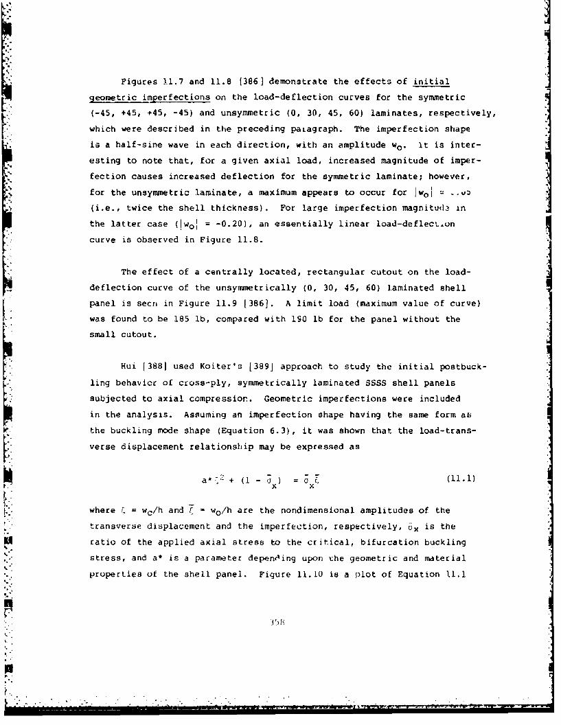
Figures 11.7 and 11.8 [386] demonstrate the effects of initial
geometric imperfections on the load-deflection curves for the symmetric
(-45, +45, +45, -45) and unsymmetric (0, 30, 45, 60) laminates, respectively,
which were described in the preceding paLagraph. The imperfection shape
is a half-sine wave in each direction, with an amplitude wo. it is inter-
esting to note that, for a given axial load, increased magnitude of imper-
fection causes increased deflection for the symmetric laminate; however,
for the unsymmetric laminate, a maximum appears to occur for Iwol = -.*
(i.e., twice the shell thickness). For large imperfection magnitude in
the latter case (!wol =-0.20), an essentially linear load-deflecLton
curve is observed in Figure 11.8.
The effect of a centrally located, rectangular cutout on the load-
deflection curve of the unsymmetrically (0, 30, 45, 60) laminated shell
panel is secri in Figure 11.9 1386]. A limit load (maximum value of curve)
was found to be 185 lb, compared with 190 lb for the panel without the
small cutout.
Hui 13881 used Koiter's [389] approach to study the initial postbuck-
ling behavior of cross-ply, symmetrically laminated SSSS shell panels
subjected to axial compression. Geometric imperfections were includedin the analysis. Assuming an imperfection shape having the same form aE
the buckling mode shape (Equation 6.3), it was shown that the load-trans-
verse displacement relationship may be expressed as
a* - + (1-a) U (11.1)
where • = wc/h and t wo/h are the nondimensional amplitudes of the
transverse displacement and the imperfection, respectively, Ox is the
ratio of the applied axial stress to the critical, bifurcation buckling
stress, and a* is a parameter depending upon the geometric and material
properties of the shell panel. Figure 11.10 is a plot of Equation 11.1
UF1
•-.8
S. . -." . .
for a* = 0.670, which corresponds to an isotropic, homogeneous shell
panel having v - 0.3, a/b w 1 and 1 - 1, where b R o0 (see Figure
10.1) is the circumferential arc length, and i is a shallowness para-
meter defined by
4.4
. • ~h (11.2)
*, The asymmetric equilibrium paths shown in Figure 11.10 are all stable:41
for positive 7 (i.e., deviation from the perfect circular cylindrical
surface by outward bulging). However, for negative Z (inward bulging),
the equilibrium paths become unstable as ý increases, and the panel is
imperfection sensitive. For a flat plate, a* is zero, Equation 11.1
yields a horizontal straight line for 1. w 0, and the equilibrium paths
are symmetric about • 0.
Figure 11.11 [3881 presents values of the a* parameter as a function
of tP, for shell panels with a/b = 1 having an infinite number of layers
and composed of five materialss isotropic, glass-epoxy, boron-epoxy,
graphite-epoxy I and graphite-epoxy II. The elastic modulus ratios for
the materials are listed in Table 11.2. It is seen in Figure 11.11 that
laminated composite shells having large EI/E 2 (e.g., graphite-epoxy II)
are less iw~perfection sensitive (i.e., smaller a*). Figure 11.12 gives
values of a' for graphite-epoxy I panels having a/b - 0.7, 1.0, 1.4 and
numbers of layers (N) = 3, 5, -. It is seen that for the shorter panels
(a/b - 0.7) imperfection sensitivity increases with increasing N, whereas
for longer panels (a/b w 1.4), it decreases with increasing N.
Bauld and Khot 1390,391. made a study of the buckling behavior of
laminated composite, cylindrical shell panels having initial imperfections.
The curved edges were loaded in compression and the straight edges were
3L(9
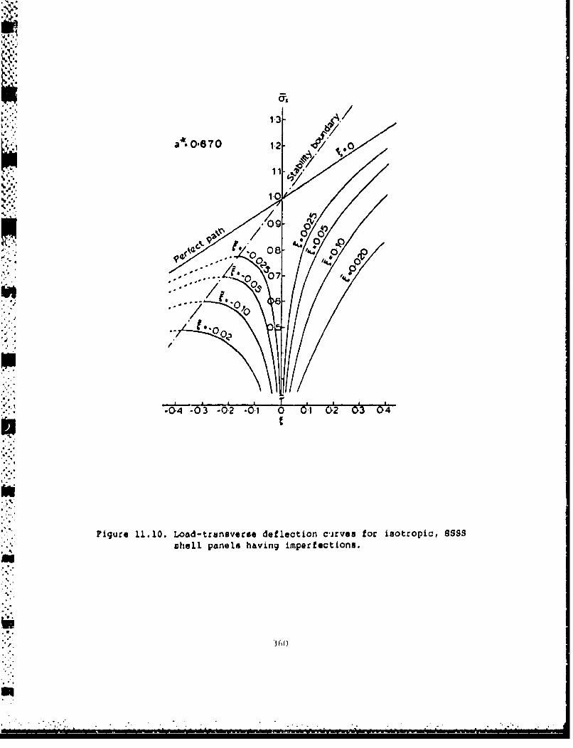
1-3
ww
-04 -03 .o.2 .0., 0 0., 02 o'3 o0
Figure 11.10. Load-transverse deflection cirves for isotropic, 8535chell panels having imperfections.
AA
039(
- . .
. . . . .. . .0"4 ' . ; . ' . - , ' . • • • . : , . i : • • • - • : • • • . L ; , ; , • • . . -• - - - = - . • . • . • . . . .. L . ÷ . . •

056
o/S:1, N co
0.5 IsotropicGlass-EP.
0.3- / Bol'on -EP.
0.2,,
0..o,
0*4 Graphite-EP. n
0 0.2 4 0-0i
Figure 11.11. Imperfection sensitivity versus shallowness parameterfo~r orthotropic, cross-ply shell panels (s/S )
361
°I
pLIz
I1
II

Table 11.2. Elastic modulus ratios used by Hui.
El ,
Material E2E 12
Isotropic 1.0 0.385 0.30Glass-epoxy 3.0 0.500 0.25Boron-epoxy 10.0 0.33i 0.22Graphite-epoxy 1 15.8 0.577 0.34Graphite-epoxy II 40.0 0.500 0.25
362~

Graphite-EP. I
0.45
03 --of 0'.÷' -'"
', /, ,
0.2-,
I ,.,01- -
0 02 4 0.6 0.8 10
Figure 11.12. Imperfection sensitivity versus shallowness parameterfor synmmtrically laminated, croso-ply, graphite-epoxy Ishell panels.

either simply supported or free. Both theoretical and experimental results
were obtained. Theoretical data were calculated using the finite difference,
energy computer code previously developed 385-387
The initial study [390) was for a set of four panels consisting of
eight layers of graphite-epoxy, symmetrically laminated in a (0/90)2s
layup. Dimensions were: a - 16 in, b - 8 in, R = 12 in, h = 0.038 in
(see Figure 10.1). Composite material properties were: E, = 20.5xlO6 psi,
E - 1.3xl06psi, G12 = O.75xl0 6psi and v12 = 0.335. The imperfection(deviation from a perfect, circular cylindrical surface) for each test
specimen was measured mechanically by means of a special fixture. For
the two test specimens used with free straight edges, imperfection data
was fit to the imperfection function
S= w ( + Cos 2×)(
where x is measured from the center of the panel. Figure 11.13 shows
load - end shortening curves determined from tests on the two specimens,
as well as three analytical curves obtained using wo = 0, 0.005, 0.010
(in) as imperfection amplitudes in Equation 11.3. Corresponding theoreti-
cal curves are seen in Figure 11.14 for the load plotted versus the least
squares average of the transverse displacement (w) computed over the
shell surface. Figure 11.15 shows the load-shortening curves for two
CSCS test specimens. Theoretical limit loads of 2522 and 4311 lb were
determined, depending upon whether the circumferential displacement at
the straight edges was not or was constrained, respectively. Curves
showing the load plotteo versus average transverse displacement for the
two types of straight edge conditions may be seen in Figures 11.16 and
11.17. The importance of the circumferential displacement along the
straight edges is evident from these plots.
Subsequent investigation of ten additional test specimens was made
1391]. All ten had the dimensions: a - 16 in, b 12 in, R a 12 in, h -
3t,

1290 ib
1170 lb
SPeect parel H).1100 / Wo. 0 0)
o00 , IC65 lb
OCO Anyfi.oI
"/cr"e$ ~ ~/ edJ:, Iur #"
//
900 - Camp-do ocr0
Sao - W. 0OC
00CZ 0304 03 06 00C18 00 03,2 00• 00:6 OCI, 0320
16x8, shell panels having geometric imperfections.
kg ns~~
-ceA

1290 ID'
1200 11i70 lb-
1000 Perfect panelVo-O0.010 8f0 aD ~0,0)
'I -W 0 0. 005
a~600
40C) Panel 16 in. x 8 inFiber -pattern : 10/90)2.
Edge condifions: Clamped curved eoges,
0 02 0.4 0.6 0 8 1.0 1.2 1.4
Norm of Ironverse diswofcernent. 2
Figure 11.14. Theoretical load-transverse displacement curves corre-sponding to ?igure :1.13.

I p I I I I I I I - I I I I I I* *4400
Suckling limit wh~en circumferential .- p4311 Ib4200 disp~lacements ore orcludtd rrgnea0017In
"40* 3800
3600 AnMaiyt'Cal IOu-Iibtiumn Pa1th
3W-- 3240 lt buckled
252 tb
.S _
circumferential b 2500 lt2400 - iSPi0COm~tntl Occur!
220:0 - rel 2250
2000 ,. Experimentoi eawoilibriij pathsi
1600
4400-
100 lPanel 16 ine a 8 in.
Goo -Fiber Pattern EO/90J1 ,Edge conditions Clomped curved edges
500 12S/mply- supported 1Trogrif
edges400
2004
I I I I I I I I I Ii0 0.2 0.4 0 6 08 1 0 1.2 1 4 1 6 16 202Z2 2 4 2 6 2.6 3.0
End - sho0rtenling z I V') in
Figure 11.1.5. Load-end shortening curves for axially loaded, 16x8,shell panels.
367

4,
It
I I " ' I " I ! I '-
'2600 - PSŽ5 lb
2400
2000 Circumferential dgsplocetment
OCCUrs freelyAfe
*11600
,~1400
-1200
1 000 Panel. 16 on x8 inFiber - pottern: [O/9012,
800 Edge condttions. Clofr.pedCrirved edges,
600 simply - supported
stoaight edges
200zooj
t I~ t t I ,I I I
0 0.04 0 (M 012 0 16 0 20
Noarn QI tronverse dspSlacemernt, w- l•wz
JFigure 11.16. Theoretical. load-transverse displacement curves corre-
sponding to Figure 11.12 (straight ed'ges not con-strained ciccumferentially).
368

44000
4200/
42000
5 3000
400
3000-
2400
22~00
1000 -4
1200 -PQg'tI 16nz8'
1000 - u-.~
*00 F
200
0 OC2 0 0ý6 0C 0 0''; C1 0 01b 0022 0.026 0030
N? e- 0 ~fofrvI'l djspircemorij, in w 11'
U ~Figjure li.t7. TheoreticJ load-displa~cem!ent curves co~rreponding to-'-urc 11.12 (OLtaighL ec~gep' aorst~aine'i circumferen-'lal~ly).
36

0.038 in (thus, only the width was different from the preceding specimen3
described earlier). Shell panels were fabricated with eight plies having
the same boron-epoxy material described above. Five panels having simply
supported straight edges had a (0/+45/-45/90)s layup and five others
with free straight edges had a (0/90)2S layup. Initial imperfection
data was measured for one CSCS panel and one CFCF panel and is shown in
Figure 11.18. This data was used as the basis for subsequent theoretical
calculaticns. The effects of axial load up:n end shortening and average
transverse displacement for the CSCS panels are shown in Figures 11.19
and 11.20, respectively. Two theoretical curves are shown in each figure,
corresponding to straight edges with or without restraint of the circum-
ferential displacements. Theoretical and experimental end-shortening
curves for the CFCF panel are ceen in Figure 11.21. Two thleoretical
curves for the average transverse displacement are given in Figure 11.22.
The solid one results from using the measured imperfection data. The
dashed curve arose from a previous study (392] which showed it to be thelimiting case when the imperfection magnitude is decreased. Figures
11.23 and 11.24 compare the transverse displacements of lines taken along
* the shell generators (i.e., axial lines) located at the straight edges
and the centerline, respectively, for the CFCF shell panel having the
"measured imperfection subjected to various axial loads. It is seen that
the free edges deflect considerably more than the centerline.
370

S57 13-51 irt.
- --
16 ; n.
CSCS Panel0.000 0.000 0.000 0.000 0.00or 0.000 0.000 0.000 0.0000.000 0.001 0.o0o -0.003 -0.007 -0.009 -0.009 -0.006 0.00o0.000 0.000 -0.001 -0.003 -0.004 -0.007 -0.006 -0.007 0.0000.000 -0.002 -0.001 0.ON0 -0.004 -0.006 -0.006 -0.007 0.0oo0.000 0.001 -0.001 0.000 -0.004 -0.O07 -0.004 -0.004 0.0000.O0O 0.000 -0.003 -0.002 -0.003 -0.007 -0.004 -0.005 0.0000.000 0.002 0.004 0.005 0.002 0.000 -0.002 -0.004 0.0000.000 0.006 0.0o3 2- 7 =I01 0.0 10 0. W7 0.004 0. 030 0.0000.000 0.000 0.000 0.000 0.000 0.000 0.000 0.000 0.000
CFCF Panel0.000 -0.006 -0.009 -0.009 -0.011 -0.012 -0.013 -0.013 0.0000.000 -0.0 -o~oos -0.001 -0.008 -0.010 -0.00 -0.5008o-o7oo0.000 0.002 0.00 -0.002 -0.005 -0.006 -0.006 -0.067 0.0000.000 -0.001 -0.001 -0.003 -0.006 -0.008 -0.007 -0.007 0.0000.000 -0.001 -0.001 -0.005 -0.007 -0.009 -0.009 -0.006 0.0000.000 -0.003 -0.002 -0.006 -0.007 -0.007 -0.008 -0.008 0.0000.000 0.000 0.000 -0.003 -0.004 -0.007 -0.006 -0.0r3 0.0000.000 0.007 0.009 0.007 0.002 -0.002 -0.003 -0.006 0.0000.000 0.010 0.014 0.012 0.008 0.002 -0.004 -0.009 0.000
Pigure 11.18. Measured initial transverse imperfections (in) for CSCSand CFCF shell panels.
371

7000
-- Nuwurical Cat& - Rl tairmdCircumfers.tiaIl Edge ODiplacements
6000 Cuir*• C.I Oat& * Free 610p Itn S77S Ib%
0 0 0 ImilrlmaI. tl Date 05510 lb
00 0 0 r(3 13 1I.pereaSntal Oat.&
A *O 5160 lb&SOSI>. o,./ B .S5000 ~~50 lb ~b "1°I
0¢0.
o &of
3000 04 16 ;n
3000 12 InCt
0 1• :•.; tF;ber Psatse -. 1. ' 101
l000 loundary Co)dition$ I Curved Edqt% Clampead.
Sirai•ht EdguS Simply SuppoOted%tat Pa ! Th•Ckness - 0.O)q In.
Finite Diflerenc e tr;d 17 a 20
25 so 75 100 125 150 175 203 225 250 275 300 325
EP{O SHORTENINC, In (210d )
Figure 11.19. Theoretical and experimental load - end shorteningresults for axially loaded, 16x12, CSCS shell panels.
372

Lk " 4000
Noo
$775 lb
iOO0l- 57 1 b
" 0) lb *ads
oo 40 75 lb oIf- 4600 lb b~l~
5000
Figure 11.20. heo~etlcal lodis- tramntsves ipaeetcre o
q. 3000
U Restrained circumferentilg
2000
aounda, y Conditions Curved Edgea Celsp.d1000 Straighbt Edges Simply-Supported
Total Patn.l Thikkais, O.D)A In.
finite Difftgrent Grid 17 a 20
0 s0 100 ISO 200 250 300 350 400 450 500 550 600
TRANSVERSE DISPLACEME(NT PARAME(TER. ,*I'IWk
Figure 11.20. Theoretical load -transverse displacement curves foraxially loaded, 16x12, CSCS shell panels.
373
3
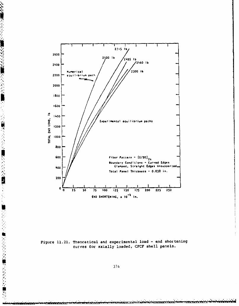
i-- I I i i - I i I I
2715 lb
2600 -2 00 lb 249 lb
21.00 -24.60 lb
NufferlIca 1 2300 lb2200 -equilibrium path
2000
1800
1600
-11.00
a Experimental equilibrlum paths
1200
S1000
800
600 -Fiber Pattern - 0/90] 21 Unpprdloundary Conditions Curved Edges
40 -0 Clamped, Straight Edges UspotdTotal Panel Thickness 0.038 in.
200
0 0 25 s0 75 100 12S 150 175 200 225 250
END SHORTENING. x 10- 4 In.
Figure 11.21. Theoretical and experimental load -end shortening
curves for axially loaded, CFCF shell panels.
374
moF// / .. _. ° , - ,...

|kO0" -- 31S Ibb
200o eosured Imperfection
2800-26000
N Mpeare f mpaction i~I 1400-
I000
4 800
z oo0
0 I I i I l a a * ! aI a
0 0.1 0.2 0.3 0.4 0.5 0.6 0.7 0.0 0. 5 .0 1. 1 1.2 1.) 1.4 1.5
TAAMSVifASE DISPLACEEINT PAAI4~?R. y/w 1I/N
Figure 11.22. Theoretical load - transverse displacement curves foraxially loaded, 16x12, CFCF shell panels.
375
• . - -. _ - . . . - - o . . o .- . , . . - . - . - - . o o . . - o

C;
2473 lb
0.02 79120 Ib
0,02500.025
312 lb
It I .t i , I I I - - I I - I I I I I I t
I4 2 6 ? 7 6 9 10 11 12 13 14 iS 16 17 14 19 20
NODAL LOCATION ALONG A GEN(AATON
Figure 11.23. Theoretical transverse displacements of the straightedge generator of a CFCF shell panel with imperfections.
376
...................................

I S I * S S S i I I I S S " t I S I '
'0.0
0.0 "247.3 Ib
"-0.04.
-o.05
.0.06,
* 3 4 6 7 1 10 II 12 1) 14 is 16 17 iS I1 20
NOOAL LOCATION ALONG A GENERATOR
Figure 11,24. Theoretical transverse displacements of the centerlinegenerator of a CFCF shell panel with imperfections.
377

AREFERENCES
1. Bryan, G. H., "On the Stability of a Plane Plate Under Thrusts in"its Own Plane, with Applications to the "Buckling" of the Sides of aShip", Proc. London Mathematical Society, Vol. 22, pp. 54-67(1981).
2. Timoshenko, S. P. and Gere, J. M., Theory of Elastic Stability,Second Edition, McGraw-Hill Book Co., 541 pp. (1961).
3. Volmir, A. S., Stability of Elastic Systems (in Russian),Gosudarstvennoye Izdatelstvo, Moscow, 879 pp. (1963). Also avail-able in English as Foreign Technology Div. translation MT 64-335(AD No. 628 508), 1028 pp. (1965).
4. Volmir, A.S., Stability of Deformable Systems (in Russian),Izdatyelstvo "Nauka", Moscow, 984 pp. (1967).
5. Ziegler, H., Principles of Structural Stability, BlaisdellPublishing Co., 150 pp. (1968).
6. Simitses, G. J., An Introduction to the Elastic Stability ofStructures, Prentice-Hall, Inc., 253 pp. (1976).
7. Brush, D. 0. and Almroth, B. 0., Buckling of Bars, Plates andShells, McGraw-Hill Book Co., 379 pp. (1975).
8. Gerard, G. and Becker, H., "Handbook of Structural Stability.Part I - Buckling of Flat Plates', NACA TN 3781, 102 pp. (1957).
9. Bulson, P. S., The Stability of Flat Plates, Chatto and Windus,Ltd., London, 470 pp. (19.1).
10. Column Research Committee of Japan, Handbook of StructuralStability, Corona Publishing Co., Ltd., Tokyo, 1064 pp. (1971).
Ii. Johns, D. J., "Shear Buckling of Isotropic and Orthotropic Plates:A Review", Aeronautical Research Council, London, Reports andMemoranda, No. 3677, 34 pp. (1971).
12. Leissa, A. W., "Advances and Trends in Plate Buckling Research",Proc. Symp. on Advances and Trends in Structures and SolidMechanics, Washington, D.C., Oct. 4-7 (1982),
13. Ambartsumyan, S. A., Theory of Anisotropic Plates, TechnomicPublishing Co., Stamford, Conn. (1970).
378
14. Ashton, J. E. and Whitney, J. M., Theory of Laminated Plates,Technomic Publishing Co., Stamford, Conn., 153 pp. (1970).
15. Chia, C.-Y., Nonlinear Analysis of Plates, McGraw-Hill Book Co.,422 pp. (1980).
16. Jones, R. M., Mechanics of Composite Materials, Scripta Book Co.,Washington, D.C., 355 pp. (1975).
17. Lekhnitskii, S. G., Anisotropic Plates, Second Edition, translatedfrom the Russian by S. W. Tsai and T. Cheron, Gordon and BreachScience Publishers, Inc., 534 pp. (1968).
18. Vinson, J. R. and Chou, T. W., Composite Materials and Their Use inStructures, Applied Science Publishers, Ltd., London, 438 pp.(1975).
19. Dong, S. B., Pieter, K. S. and Taylor, R. L., "On the Theory ofLaminated Anisotropic Shells and Plates", Journal of theAeronautical Sciences, Vol. 29. pp. 959-975 (1962).
20. Reissner, E. and Stavsky, Y., "Bending and Stretching of CertainTypes of Heterogeneous Aeolotropic Elastic Plates", Trans. ASME,Journal of Applied Mechanics, Vol. 9, pp. 402-408 (1961).
21. Bergmann, S. and Reissner, H., "Neuere Probleme aus der Plugzeug-statik. Ueber die Knickung von Wellblechstreifen bel Schub-beanspvuchung", Z.F.M., Vol. 20 (1929).
22. Schmieden, C., "Das Ausknicken versteifter Bleche unter Schub-beanspruchung", Z.F.M., Vol. 21 (1930).
23. Gerard, G. and Becker, H., "Handbook of Structural Stability. PartVII. - Strength of Thin--Wing Constructiono, Technical Note, NACA TND-162, 83pp. (1959).
24. Baiabukh, L. I., "Stability of Plywood Sheets" (in Russian),Tekhnika Vozdushnogo Flota (1937).
25. March, H., "Buckling of Flat Plywood Plates in Compression, Shear,or Combined Compression and Shear", Forest Products Lab., Madison,Wis.,Rept. No. 1316 (1942).
26. Green, A. E. and Hearmon, R. F. S., "The Buckling of FlatRectingular Plywood Plates", Philosophical Magazine, Series 7,Vol. 36, p. 659 (1945),
379

27. Almroth, B. 0., "Design of Composite Material Structures forBuckling - An Evaluation of the State-of-the-Art", Wright PattersonAir Force Base, Technical Report AFWAL-TR-81-3102, 66 pp. (1981).
28. Bert, C. W., "Optimal Design of Composite-Material Panels forBusiness Airciaft", Presented at the Society of AutomativeEngineers Business Aircraft Meeting, Wichita, Kansas, Mar.29 -April 1,1977, 13 pp. (1977).
29. Bert. C. W. and Francis, P. H., "Composite Material Mechanics:Structural Mechanics", AIAA Journal, Vol. 12, No. 9, pp. 1173-1186(1974).
30. Leissa, A. W., "Advances in Vibration, Buckling and PostbucklingStudies on Composite Plates*, Composite Structures, (Proc. FirstInter. Conf.. on Compos. Struct., Paisley, Scotland, Sept. 16-18,1981), Edited by I.H. Marshall, Applied Science Publishers,pp. 312-334 (1981).
31. Leissa, A. W., "Buckling of Composite Plates", CompositeStructures, Vol. 1, pp. 51--66 (1983).
32. Fogg, L., "Stability Analysis of Laminated Materials", State of theArt Design and Analysis of Advanced Composite Materials, LockheedCalifornia Company, Sessions I and II, 162 pp. (1981).
33. Leissa, A. W. and Vagins, M., "The Design of Orthotropic Materialsfor Stress Optimization", International Journal of Solids andStructures, Vol. 14, pp. 517-526 (1978).
34. Mandell, J. F., "An Experimental Study of the Buckling ofAnisotropic Plates", M.S.Thesis (and Report No. 23), Case WesternReserve University, Division of Solid Mechanics, Structures andMechanical Design, 315 pp. (June, 1968).
35. Mandell, J. F., "An Experimental Investigation of Anisotropic Fiber
Reinforced Plastic Plates", Technical Report, AFML TR 68-281S~(1968).
36. Hoff, N. J., Boley, B. A. and Coan, J. M., "The Development of a
Technique for Testing Stiff Panels in Edgewise Compression", Proc.Society of Experimental Stress Analysis, Vol. 5, No. 2, pp. 14-24(1948).
37. Dekker, J., Kuipers, J., et al., "Buckling Strength of Plywood.Results of Tests and Design Recommendations", Heron, (Delft),Vol. 23, No. 4, pp. 5-59 (1978).
- 380

38. Knutsson, L., "Theoretical and Experimental Investigation of theBuckling and Post-Buckling Characteristics of Flat CFRP PanelsSubjected to Compression", Aeronautical Research Institute ofSweden, Stockholm, Structures Dept., Report No.: FFA-TN-HU-1934,26 pp. (Aug. 1978).
39. Willey, B. T., "Instability of Glass Fiber Reinforced PlasticPanels under Axial Compression", Stanford Univ., California, Dept.of Aeronautics and Astronautics, Technical Report, Contract: )A-44-177-AMC-115(T), 62 pp. (Sept. 1971).
40. Southwell, R. V., "On the Analysis of Experimental Observations in
Problems of Elastic Stability", Proc. Royal Society, rondon,
Series A, Vol. 135, p. 601 (1932).
41. Chamis, C. C., "Micro and Structural Mechanics and StructuralSynthesis of Multilayered Filamentary Composite Panels", Case
Western Reserve University, Rept. No. SMSMDD 9, Contract No.AF33(615)-3112 (1967).
42. Ashton, J. E., "Anisotropic Plate Analysis", General DynamicsCorp., Research and Engineering Rept. FZM-4899, 161 pp. (Oct.
1967).
43. Chamis, C. C., "Buckling of Anisotropic Composite Plates", Proc.
ASCE, Journal of the Structural Division, Vol. 95 (ST 10),pp. 2119-2139 (1969).
44. Chamis, C. C., "Buckling of Anisotropic Plates, Closure and
Errata", Proc. ASCE, Journal of the Structural Division, Vol 97,
pp. 960-962 (1971).
45. Chamis, C. C., "Theoretical Buckling Loads of Boron/Aluminum and
Graphite/Resin Fiber-Composite Anisotropic Plates", Technical Note,
NASA TN D-6572, 36 pp. (Dec. 1971).
46. Chamis, C. C., "Buckling of Boron/Aluminum and Graphite/Resin Fiber
Composite Panels", Proc. Natl. SAMPE Conf. on Space ShuttleMaterials (1971).
47. Das, Y. C., "Buckling of Rectangular Orthotropic Plates", Applied
Scientific Research (A), Vol. II, pp. 97-103 (1962).
48. Engineering Sciences Data Unit., London, England, "Buckling of FlatRectangular Orthotropic Plates (Computer Program)", ESDU-73003,32 pp. Mar. 1973).
381

49. Gerard, G. "Minimum Weight Analysas oi Orthotropic Plates UnderCompressive Loading", Journal of Aerospace Sciences, Vol. 27,No. 64, pp. 21-26,64 (1960).
50. Hudson, R. A., Girn, J. and Simitses, G. J., "Buckling Performanceof Folding Cartons", Taepi, Vol. 62, No. 10, pp. 95-98 (1979).
51. Linsenmann, D. R., "Stability of Plates of Composite Materials",AIAA 13th Aerospace Sciences Meeting, Pasadena, Calif., 20-22 Jan.(1975).
52. Pfluger, A., "The Buckling of Anisotropic Rectangular Plates. (ZumBeulproblem der anisotropen Rechteckplatte)" (in German), A
Ingenieur-Archiv, Vol. 16, No. 2, pp. 111-120 (1947).
53. Samuelson, A., Vestergren, P., Knutsson, L., Wangberg, K. G. andGamziukas, V., "Stability and Ultimate Strength of Carbon FiberReinforced Plastic Panels", "Advances in Composite Materials".Pergamon Press, Headington Hill Hall, Oxford, England, (Proc. 3rdIntern. Conf. on Composite Materials, Paris, France, 26-29 Aug.(1980))
54. Tsay, C. S. and Reddy, J. N., "Bending, Stability and FreeVibrations of Thin Orthotropic Plates by Simplified Mixed FiniteElements", Journal of Sound and Vibration, Vol. 59, No. 2, pp. 307-311 (1978).
55. Yamana, M., "On the Elastic Stability of Aeroplane Structures" (inJapanese), J. Faculty of Engineering, Univ. of Tokyo, Vol. 20(1933).
56. Zizicas, G. A., "Stability of Thin Anisotropic Elastic Plates",Ph.D.Dissertation, Uriv. of California, Los Angeles, Calif. (1952).
57. Wittrick, W. H., "Correlation Between Some Stability Problems forOrthotropic and Isotropic Plates under Bi-Axial and Uni-AxialDirect Stress", Aeronautical Quarterly, Vol. 4 (Part 1), pp. 83-92(1952).
58. Brunelle, E. J. and Oyibo, G. A., "Generic Buckl.ng Curves forSpecially Orthotropic Rectangular Plates", AIAA Journal, (Aug.1983).
59. Oyibo, G. A., "The Use of Affine Transformations in the Analysis ofStability and Vibrations of Orthotropic Plates", Ph.D.Thesis,Rensselaer Polytechnic Institute, Troy, N.Y. (1981).
A
0;
A

60. Harris, G. Z., "The Buckling of Orthotropic Rectangular Plates,including the Effect of Lateral Edge Restraint", InternationalJournal of Solids and Structures, Vol. 11, No. 7/8, pp. 877-885(1975).
61. Schmieden, C., "Das Ausknicken eines Plattenstreifens unter Schub-und Druckkraften", Zeitschrift fur Angewandte Mathematik, Vol. 15(1935).
62. Seydel, E., "Contribution to the Problem of Buckling of ReinforcedPlates by Tangential Stresses", (in German), DVL-Bericht Luftfahrt-forschung, Vol. 8, No. 2, p. 71. (1930). English translation alsoavailable as NACA TM-602.
63. Seydel, E., "Schubknickversuche mit Wellblechtafeln", Jahrbuch DVL,R. Oldenburg, Berlin, p. 233 (1931).
64. Seydel, E., "Ausbeul-Schublast rechteckiger Platten (Zahlen, Bei-spiele und Versuchsergebnisse)", Zeitschrift far Flugtechnik undMotorluftsch., Vol. 24 (1933).
65. Seydel, E., "Buckling of Rectangular Isotropic or Orthogonal-Aninotropic Plates under Shear Stresses*, NASA TT F-16240, (Transl.from Ingenieur-Archiv.)
66. Stavsky, Y. and Hoff, N. J., "Mechanics of Composite Structures,Chapter I", in Composite Engineering Laminates, Editor: A. G. H.Dietz, MIT Press, pp. 5-59 (1969).
67. Southwell, R. V. and Skan, S. W., "On the Stability under ShearingForces of a Flat Elastic Strip", Proc. Royal Society of London,Series A, Vol. 105, pp. 582-607 (1924).
68. Housner, J. M. and Stein, M., "Numerical Analysis and ParametricStudies of the Buckling of Composite Orthotropic Compression andShear Panels", Technical Note, NASA TN D-7996, 103 pp. (Oct. 1975).
69. Stein M. and Housner, J. M., "Application of a Trigonometric FiniteDifference Procedure to Numerical Analysis of Compressive and ShearBuckling of Orthotropic Panels", Computers & Structures, Vol. 9,No. 1, pp. 17-25 (1978).
70. Anon., "Structural Optimization of Six Different Types of Rectan-gular Plates Subjected to Combined Shear and Biaxial CompressiveLoading", Lockheed-California Company, Rept. LR 21662 (1968).
303

71. Davenport, 0. B. an Bert, C. W., "Buckling of Orthotropic, Curved,Sandwich Panels Subjected to Shear Edge Loads", Journal of Aircraft,
Vol. 9, No. 7, pp. 477-480 (1972).
72. Libove, C., "Buckling of Orthotropic Plates", 4th edition of
Structural Stability Research Council, "Guide to Stability Design
Criteria for Metal Structures", 10 pp. (1981).
73. Sekeriy-Tsenkovich, Proc. 5th International Congress of Aeronautics
(The Hague, Netherlands), Vol. 2, pp. 1071-1080 (1930).
74. Sekerzh-Zch'kovich, "Calculating the Stability of Plywood Sheets as
an Anisotropic Plate" (in Russian), Trudy Ts AGI, No. 76 (1931).
75. Smith, R. C. T., "The Buckling of Plywood Plates in Shear",
Australian C.S.I.R., Aeronautical Research Labs (Melbourne), Rept.
SM 51 (1946).
76. Vestergren, P., "A Theoretical and Experimental Investigation Cf
the Buckling Behaviour of Rectangular CFRP Panels Subjected to
Shear Loading", Aeronautical Research Institute of Sweden,Stockholm, Rept. FFA HU-1818 (1977).
77. Sandorff, P. E., "Design of Structural Models with Application to
Stiffened Panels Under Combined Shear and Compression", Journal ofAeronautical Sciences, Vol. 23, pp. 623-632 (1956).
78. Zahn, J. J. and Romstad, K. M., "Buckling of Simply Supported
Plywood Plates under Combined Edgewise Bending and Compression",
U.S. Forest Service, Research Paper FPL 50, 20 pp. (Dec. 1965).
79. Thierauf, G., "An Elementary Method for Calculation of Buckling
Valuses for Orthotropic and Isotropic Rectangular Plates. (Ein
elementarer Weg zur Berechnung von Beulwerten orthotroper undisotroper Rechteckplatten)" (in German), Ph.D.Thesis, TechnischeHochschule Munchen (West Germany), No. 1, 77 pp. (Jan. 1969).
80. Knoepke, K.-H., "Contribution to the Calculation of the Buckling
Loads of Plate Strips with Heat Stresses Variable Across the Widthof the Plate" (in German), Deutsche Forschungsanstalt fdr Luft- und
Raumfahrt, Brunswick (West Germany), Institut fur Flugzeugbau, DLR-
FB-68-33, 31 pp. (May 1968).
81. Nowacki, W., "On Stability Problems of an Orthotropic Plate" (in
French), Archives of Mechanics Stosowanej, Vol. 2, No. 3, pp. 169-182 %1950).
384
82. Brukva, N. F., "Stability of Rectangular Orthotropic Plates", (inRussian), Prikladnaya Mekhanika, Vol. 4, No. 3, pp. 77-85 (1968).
83. Anon., "Buckling of Orthotropic Plates (Corrugated PlateApplications)", Bell Aerosystems, Rept. 7-60-941001 (1961).
84. Bowen, D. V. and Ayers, K. B., "Buckling and Failure of Metal FacedCFRP Sheets in Compression", Composites, Vol. 6, No. 2, pp. 69-74(1975).
85. Dale, F. A. and Smith, R. C. T., "Grid Sandwich Panels inCompression", Australian Council for Aeronautics, Melbourne, Rept.ACA-16 (April 1945).
86. Mazzolani, F. M. and Visconti, I. C., "Stability of CompositePlates" (in Italian), Aerotecnica Missili e Spazio, Vol. 53, No. 4,pp. 261-276 (1974).
87. Sharifi, P., "Nonlinear Buckling Analysis of Composite Shells",AIAA Journal, Vol. 13, pp. 729-734 (1975).
88. Shuleshko, P., "Reduction Method for Buckling Problems of Ortho-tropic Plates", Aeronautical Quarterly, Vol. 8, pp. 145-156 (1957).
89. Smith, R. C. T., "The Buckling of Flat Plywood Plates in Com-pression", Australian Council for Aeronautics, Melbourne, Rept.ACA-12 (Dec. 1944).
90. Soni, S. R. and Amba Rao, C. L., "Vibrations of OrthotropicRectangular Plates Under Inplane Forces", Computers & Structures,Vol. 4, No. 5, pp. 1105-1115 (1974).
91. Suarez, J. A., "Advanced Composite Wing Structures - StabilityAnalysis of Advanced Filamentary Composite Panels", GrummanAircraft Engineering Corp., Tech. Rept. AC-SM-8087 (1970).
92. Viswanathan, A. V., Soong, T. C. and Miller, R. E., Jr., "BucklingAnalysis for Axially Compressed Flat Plates, Structural Sections,and Stiffened Plates Reinforced with Laminated Composites",Contractor Report, NASA CR-1887, 75 pp. (Nov. 1971).
93. Viswanathan, A. V., Soong, T. C. and Miller, R. E., Jr., BucklingAnalysis for Structural Sections and Stiffened Plates ReinforcedWith Laminated Composites", International Journal of Solids andStructures, Vol. 8, No. 3, pp. 347-367 (1972).
385

94. Garashchuk, I. N., Zamula, G. N. and Prikazchikov, V. G.,"Numerical Solution of Plate-Stability Problems", Soviet AppliedMechanics, Vol. 14, No. 5, pp. 86-91 (1978).
95. Leissa, A. W., "The Free Vibration of Rectangular Plates", Journalof Sound and Vibration, Vol. 31, pp. 257-293 (1973).
96. Shuleshko, P., "Soludion of Buckling Problems by Reduction Method",Proc. ASCE, Journal of the Engineering Mechanics Division, Vol. 90,pp. 147-169 (1964).
97. Massey, C., "The Elastic Buckling of Orthotropic RectangularPlates", Institution of Engineers, Australia, Civil EngineeringTrans., Vol. 13, No. 1, pp. 63-65 (1971).
98. Holston, A., Jr., "Buckling of Orthotropic Plates with one FreeEdge", AIAA Journal, Vol. 8, No. 7, pp. 1352-1354 (1970).
99. Lackman, L. M. and Ault, R. M., "Minimum-Weight Analysis ofFilamentary Composite Wide Columns", Journal of Aircraft, Vol. 5,No.2, pp. 184-190 (1968).
100. Anon., "Advanced Composite Wing Structures; Preliminary Analysisand Optimization Methods", Grumman Aircraft Engrg. Corp., TechnicalReport, AC-SM-7843 (1968).
101. Baharlou, B., "Vibration and Buckling of Laminated Composite Plateswith Arbitrary Edge Conditions", Ph.D.Dissertation, Ohio StateUniversity, 141 pp. (1985).
102. Banks W. M. and Rhodes, J., "The Buckling Behaviour of ReinforcedPlastic Box Sections", PLoc. 12th Reinforced Plastics Congress,Brighton, Sussex, England, pp. 85-88 (1980).
103. Halstead, D. W., Tripp, L. L., Tamekuni, M. and Baker, L. L.,"BUCLAP2: A Computer Program for Instability Analysis of LaminatedLong Plates Subjected to Combined inplane Loads", ContractorReport, NASA CR-132299, 96 pp. (Aug. 1973).
104. Oeverli, V. and Viswanathan, A. V., "BUCLAP - A Computer Programfor Uniaxial Compressive Buckling Loads of Orthotropic LaminatedPlates", Contractor Report, NASA CR-111869 (1971).
105. Schultz, H.-G., "Zum Stabilitatsproblem elastisch eingespannterorthotroper Platten", Stahlbau, Vol. 32, pp. 22-25 (1963).
386
• • • -*° .- -.-

106. Sakata, T., "A Reduction Method for Vibrating and Buckling Problemsof Orthotropic Continuous Plates", Journal of Sound and Vibration,Vol. 49, No. 1, pp. 45-52 (1976).
107. Nowacki, W., "Bending and Buckling of Certain Types of ContinuousOrthotropic Plates (Flexion et Flambage d'un certain type de plaquescontinues orthotropes)" (in French), Publ. intern. Assoc. BridgeStruct. Engrg., 3rd Congress, prelim. publ., pp. 519-530 (1948).
108. Leissa, A. W., Vibration of Plates, NASA SP-160, U.S. Govt.Printing Office, Washington, D.C., 353 pp. (1969).
109. Dickinson, S. M., "The Buckling and Frequency of Flexural Vibrationof Rectangular Isotropic and Orthotropic Plates Using Rayleigh'sMethod', Journal of Sound and Vibration, Vol. 61, No. 1, pp. 1-8(1978).
11n. Warburton, G. R., "The Vibration of Rectangular Plates", Proc. ofthe Institut of Mechanical Engineers, Vol. 168, pp. 371-384 (1954).
111. Leissa, A. W., "The Free Vibration of Rectangular Plates", Journal
of Sound and Vibcation, Vol. 31, pp. 257-293 (1973).
112. Ashton, J. E. and Love, T. S., "Experimental Study of the Stability
of Composite Plates", Journal of Composite Materials, Vol. 3,pp. 230-242 (1969).
113. Chia, C. Y. and Prabhakara, M. K., "Nonlinear Analysis of Ortho-tropic Plates", Journal of Mechanical Engineering Science, Vol. 17,No. 3, pp. 133-138 (1975).
114. Srinivasan, R. S. and Ramachandran, S. V., "Stability of GenerallyOrthotropic Skew Plates", Technical Notes, Proc. ASCE, Journal ofthe Engineering Mechanics Division, Vol. 102, No. 3, pp. 569-572(1976).
115. Mar, J. W. and Lagace, P. A., "Design Technology of AdvancedComposites", Technical Report, AFWAL TR-82-4178, 57 pp. (Nov.1982).
116. Marquis, W. A., "Fatigue Behavior of Graphite/Epoxy Plates UnderShear Buckling", S.M.Thesis, Dept. of Aeronautics and Astronautics,Mass.Inst.Tech. (1982).
117. Simitses, G. J. and Girl, J., "Buckling of Rotationally RestrainedOrthotropic Plates Under Uniaxial Compression", Journal ofComposite Materials, Vol. 11, pp. 345-364 (1977).
387

118. Crouzet-Pascal, J., "Comment on Buckling of Rotationally RestrainedOrthotropic Plates Under Uniaxial Compression", Journal ofComposite Materials, Vol. 12, pp. 215-218 (1978).
119. Simitses, G. J. and Girl, J., "Response to Dr. Crouzet-Pascal'sComment", Journal of Composite Materials, Vol. 12, pp. 218-219(1978).
120. Wittrick, W. H., "Rationalization of Anisotropic BucklingProblems", "Contributions to the Theory of Aircraft Structuresn,Van der Neut Anniversary Vol., Delft University Press, pp. 359-377(1972).
121. Anon., "A Displacement-Type Finite Element Analysis of BifurcationBuckling of Rectangular Plates Based on a Conforming FiniteElement", Lockheed-California Co., Rept. LR 23841 (1970).
122. Crouzet-Pascal, J., "Buckling Analysis of Laminated CompositePlates", Fibre Science and Technology, Vol. 11, pp. 413-446 (1978).
123. Chao, C. C., Koh, S. L. and Sun, C. T., "Optimization of Bucklingand Yield Strengths of Laminated Composites", AIAA Journal(Synoptic), Vol. 13, No. 9, pp. 1131-1132 (1975). Full paperavailable from NTIS as N75-19370, 33 pp. (May 1974).
124. Chao, C. C., "Optimization of Strength and Stability of LaminatedComposites", Ph.D.Thesis, Purdue University, 170 pp. (1974).
125. Bert, C. W. and Chen, T. L. C., "Optimal Design of Composite-
Material Plates ot Resist Buckling Under Biaxial Compression",Trans. Japan Soc., Composite Materials (JSCM), Vol. 2, No. 1,pp. 7-10 (1976).
126. Hayashi, T., "Optimum Design of Cross- and Angle-Plied LaminatedComposite Plates Under Compression", Composite Materials andStructures (Japan), Vol. 3, No. 2, pp. 18-20 (1974).
127. Hayashi, T., "Optimization for Elastic Buckling Strength of Fiber-Reinforced Composite Structures - Columns, Plates and Cylinders",Proc. 1974 Symp. on Mechanical Behavior of Materials, Kyoto, Japan,21-24 August (1974).
128. Kominar, V. A., "Stability of a Rectangular Glass-Plate" (inRussian), Bulletin of the All-Union Scientific Research Institute
* of Rail Transport, Moscow, Vol. 2, pp. 35-38 (1967).
388
10
'... .... .. - . . . . . .. .-...- .::;:• :_ ..........
i" -••-'"'-"•'-'-:•:• •-: •: "" :: •"' '

129. Kominar, V. A., "Influence of the Reinforcement Pattern on theStability of a Rectangular Glass-Plastic Plate" (in Russian),Mekhanika Polymerov, Vol. 6, pp. 1136-1139 (1967).
130. Konishi, D. Y. and Lee, K. J., "Strength and Stability Optimizationof an Unstiffened Panel Under Multiple Inplane Loads", Ch. 1.8,Advanced Composites Design Guide, 3rd Ed., Air Force MaterialsLab., WPAFB, Ohio (1973).
131. Lukoshevichyus, R. S., "Minimizing the Mass of Reinfc.. adRectangular Plates Compressed in Two Directions in a MannerConductive Toward Stability", Polymer Mechanics, Vol. 12, No. 6,pp. 929-933 (1977).
132. Rothwell, A., "Optimum Fibre Orientations for the Buckling ofComposite Materials", Fibre Science and Technology, Vol. 2,pp. 111-122 (1969).
133. Schmit, L. A., Jr. and Farshi, B., "Optimum Design of LaminatedFibre Composite Plates", International Journal for NumericalMethods in Engineering, Vol. 11, No. 4, pp. 623-640 (1977).
134. Tashkandi, M. A., "Optimum Design of Laminated Fiber CompositePlates", Ph.D.Thesis, California University, Los Angele, 123 pp.(1976).
135. Verette, R. M., "Stiffness, Strength and Stability Optimization ofLaminated Composites", Northrop Aircraft Corp., Hawthorne, Calif.,Report NOR-70-138,(1970).
136. Thielemann, W., "Contribution to the Problem of Buckling ofOrthotropic Plates, With Special Reference to Plywood", TechnicalMemorandum, NACA TM-1263, 122 pp. (Aug. 1950).
137. Thielemann, W., "Buckling of Anisotropic Plate Strips" (in German),Deutsche Versuchsanstalt Luftfahrt E.V., Report No. 16, 70 pp (June1956).
138. Ashton, J. E. and Waddoups, M. E., "Analysis of AnisotropicPlates", Journal of Composite Materials, Vol. 3, pp. 148-165(1969).
139. Davis, J. G. and Zender, G. W., "Compressive Behavior of PlatesFabricated from Glass Filaments and Epoxy Resin", Technical Note,NASA TN-D-3918 (1968).
389
,.. - o.- .. - -.. - , ._ 4 ., •. - .. . • .. . . -. . . . . ..- - .- ..- .,--.-. ."- . - ..- . -

140. Movsisyan, L. A. and Peshtmaldzhyan, D. V., "On the Equations ofStability and Vibrations of Anisotropic Plates" (in Russian),Izvestiya Akademii Nauk Armyanskoi SSR, Mekhanika, Vol. 26, No. 6,pp. 18-28 (1973).
141. Petrov, Yu. P., "Calculating Flexure and Stability of Rec'and Nonrectangular Anisotropic Plates by the DifferentialDifference Method", WPAFB, Foreign Technology Div., Rept.23-461-70, 23 pp. (Oct. 1970).
142. Prachuktam, S., "Static, Vibration, and Stability Analyses of
Anisotropic Plates", Ph.D.Thesis, The University of Akron, 200 pp.(1974).
143. Robinson, J. C. and Blackburn, C. L., "Evaluation of a Hybrid,Anisotropic, Multilayered, Quadrilateral Finite Elementa, NASA TP-1236, 28 pp. (Aug. 1978).
144. Sarkisyan, V. S. and Movsisyan, L. A., "A Method for Determiningthe Critical Loads on Anisotropic Plates", Soviet EngineeringJournal, Vol. 5, No. 4, pp. 600-602 (1965).
145. Sawyer, J. W., "Flutter and Buckling of General Laminated Plates",Journal of Aircraft, Vol. 14, No. 4, pp. 387-393 (1977).
146. Silberstein, J. P. 0. and Smith, R. C. T., "3-Ply Flat Panels inEnd Compression at 450 to the Grain", Division of Aeronautics,C.S.I.R. Australia, Rept. S. M. 42, (1944).
147. Whitney, J. M., "Analysis of Anisotropic Rectangular Plates", AIAAJournal, Vol. 10, No. 10, pp. 1344-1345 (1972).
148. Whitney, J. M., "On the Analysis of Anisotropic RectangularPlates", WPAFB, Air Force Materials Lab., Rept. AFML-TR-72-76,24 pp. (Aug. 1972).
149. Wiggenraad, J. F. M., "A Finite Element Model, to Study theBuckling Behavior of General Orthotropic, Midplane Symmetric andElastic Plates", National Lucht-en Ruimtevaartlaboratorium, TheNetherlands, Technical Report, NLR TR 77062 U, 14 pp. (1977).
150. Sandorff, P. E., Lockheed-California Company, Private communication,(May 14, 1984).
390

151. Ashton, J. E. and Love, T. S., "Shear Stability of LaminatedAnisotropic Plates", Composite Materials: Testing an Design, ASTMSTP 460, pp. 352-361 (1969).
152. Freiberger, W., Shaw, F. S., Silberstein, J. P. 0. and Smith, R. C. T.,"Plywood PantA• in End Compression: Flat Panels with Grain atVarious Angles to Direction of Loading", Australian Council forAeronautics, No. 30, pp. 3-35 (Jan. 1947).
153. Ringelstetter, L. A., "Buckling Tests of Flat Plywood Plates inCompression with Face Grain 450 to Load - Loaded Edges Clamped,Others Simply Supported", Forest Products Lab. Rept. No. 1316-J.,7 pp. (1949).
154. Whitney, J. M., "Fourier Analysis of Clamped Anisotropic Plates",Trans. ASME, Journal of Applied Mechanics, Series E, Vol. 38, No. 2,pp. 530-532 (1971).
155. Whitney, J. M., "Fourier Analysis of Clamped Anisotropic Plates",Wright-Patterson AFBML, Ohio, Technical Rept. AFML-TR-70-281,17 pp. (Feb. 1971).
156. Fraser, H. Jr., "Bifurcation Type Buckling of Generally OrthotropicPlates", Ph.D.Dissertation, University of Illinois (1968).
157. Fraser, H. R., J,,. and Miller, R. E., "Bifurcation Type Buckling ofGenerally Orthotropic Clamped Plates", AIAA Journal, Vol. 8, No. 4,pp. 707-712 (1970).
158. Jones, R. M., "Buckling and Vibration of Unsymmetrically LaminatedCross-Ply Rectangular Plates", AIAA Journal, Vol. 11, No. 12, pp.1626-1632 (1973).
159. Stavsky, Y., "On the Theory of Heterogeneous Anisotropic Plates",Doctoral Thesis, Massachusetts Institute of Technology, Cambridge,Mass. (1959).
160. Smith, C. B. (Forest Products Laboratory), Letter to E. Reissner(1961).
161. Broutman, L. J., Haslett, W. H., Krokosky, E. M., Roy, J. R. andMcGarry, F. J., "Investigation of Mechanics of ReinforcedPlastics', Aeronautical Systems Div., WPAFB, WADD-TR-60-746, Pt. II(1962).
391
39.. . . . . . . . . .. . . . . . . . . .... . . . . . . . . . . . .-.- - - - - -

162. Ashton, J. E., "Approximate Solutions for Unsymmetrical LaminatedPlates", Journal of Composite Material, Vol. 3, pp. 189-191 (1969).
163. Whitney, J. M., "Bending, Vibrations, and Buckling of LaminatedAnisotropic Rectangular Plates", Wright Patterson AFBML, Ohio,Technical Rept. AFML-TR-70-75, 35 pp. (Aug. 1970).
164. Whitney, J. M., "The Effect of Boundary Conditions of the Responseof Laminated Composites", Journal of Composite Materials, Vol. 4,pp. 192-203 (1970).
165. Whitney, J. M., "A Study of the Effects of Coupling Between Bendingand Stretching on the Mechanical Behavior of Layered AnisotropicComposite Materials", Ph.D.Dissertation, Ohio State University(1968), also Tech. Rept. AFML-TR-68-330, 80 pp. (Apr. 1969).
166. Whitney, J. M. and Leissa, A. W., "Analysis of Heterogeneous Aniso-tropic Plates" Trans. ASME, Journal of Applied Mechanics, Vol. 36,No. 2, pp. 261-266 (1969).
167. Leissa, A. W. and Kadi, A. S., "Curvature Effects on Shallow ShellVibrations", Journal of Sound and Vibration, Vol. 16, pp. 173-187(1971).
168. Leissa, A. W., Vibration of Shells, NASA SP-288, U.S.Govt. PrintingOffice, 428 pp. (1973).
169. Chen, T. L. C. and Bert, C. W., "Design of Composite-Material
Plates for Maximum Uniaxial Compressive Buckling Load", Proc. ofthe Oklahoma Academy of Science, Vol. 56, pp. 104-107 (1976).
170. Jones, R. M., Morgan, H. S., Whitney, J. M., "Buckling andVibration of Antisymmetrically Laminated Angle-Ply RectangularPlates", Trans. ASME, Journal of Applied Mechanics, Vol. 12, pp.
1143-1144 (1973).
171. Whitney, J. M. and Leissa, A. W., "Analysis of a Simply Supported
Laminated Anisotropic Rectangular Plate", AIAA Journal, Vol. 8,No. 1, pp. 28-33 (1970).
172. Kicher, T. P. and Mandell, J. F., "A Study of the Buckling ofLaminated Composite Plates", AIAA Journal, Vol. 9, No. 4, pp. 605-613 (1971).
173. Monforton, G. R., "Discrete Element Finite Displacement Analysis ofAnisotropic Sandwich Shells", Ph.D.Thesis, Case Western ReserveUniversity (1970).
392
. .. . . . . .. . . . . . . . .
S-.. - . . .
..- ... . . . . . . ..- ~ .-. ~..- ~. -. -_

174. Chailleux, A., Hans, Y. and Verchery, G., "Experimental Study ofthe Buckling of Laminated Composite Columns and Plates",I•ternational Journal of Mechanical Sciences, Vol. 17, No. 8,pp. 489-498 (1975).
175. Chailleux, A. and Hans, Y., Internal Report No. 007, ENSTA (Paris)(1972).
176. Verchery, G., Inturnal Report No. 010, ENSTA (Paris) (1973).
177. Whitney, J. M., "Shear Buckling of Unsymmetrical Cross-Ply Plates",Journal of Composite Materials, Vol. 3, pp. 359-363 (1969).
178. Hui, D., "Shear Buckling of Anti-Synmmetric Cross-Ply RectangularPlates', Fibre Science and Technology, Vol. 21, pp. 327-340 (1984).
-79. Hirano, Y., "Optimum Design of Laminated Plates Under Shear",Journal of Composite Materials, Vol. 13, pp. 329-334 (1979).
180. Hirano, Y., "Stability Optimization of Laminated Composite Plates",Tokyo University Japan, Inst. of Space and Aeronautical Science,ISAS-579, Vol. 45, No. 4. Also NASA CR-163456, 19 pp. (July 1980).
181. Chia, C. Y. and Prabhakara, M. K., *Postbuckling Behavior ofUnsymmetrically Layered Anisotropic Rectangular Plates", Trans.ASME, Journal of Applied Mechanics, Vol. 41, pp. 155-162 (1974).
182. Harris, G. Z., "The Buckling and Post-Buckling Behavior of Com-positj Plates under Biaxial Loading", International Journal ofMechanical Sciences, Vol. 17, No. 3, pp. 187-202 (1975).
183. Jones, R. M., "Mechanics of Composite Materials with DifferentModuli in Tension and Compression", Southern Methodist University,'allas, Texas, Dept. of Civil and Mech. Engineering, Grant: AF-AFOSR-2532-73, Project: AF-9782, 41 pp. (July 1975).
184. Jones, R. M., "Mechanics of Composite Materials with DifferentModuli in Tension and Compression", Southern Methodist University,Dallas, Texas, Dept. of Civil and Mech. Engineering, Grant: AF-APOSR-2532-73, Projects AF-9782, 48 pp (July 1974).
185. Kicher, T. P., "Predicting Structural Behavior of Composites",Proc. 26th Annual Tech. Conf. of the Society of the PlasticIndustry, Inc. (1971).
393

186. Prabhakara, M. K. and Kennedy, J. B., "Nonlinear Behaviour ofUnsymmetric, Angle-Ply, Rectangular Plates under In-Plane EdgeShear", Journal of Mechanical Engineering Science, Vol. 21, No. 3,pp. 205-214 (1979).
187. Sawyer, J. W., "Flutter of Laminated Plates in Supersonic Flown,Technical Memorandum, NASA TM X-72800 (1975).
188. Zhang, Y. and Matthews, F. L., "Initial Buckling of Curved Panelsof Generally Layered Composite Materials", Composite Structures,Vol. 1, pp. 3-30 (1983).
189. Marshall, I. H., Little, W. and El Tayeby, M. M., "The Stability ofComposite Panels with Holes", Proc. Reinforced Plastics Congress,Brighton, U.K., pp. 139-141 (1984).
190. Martin, J., "Buckling and Postbuckling of Laminated CompositeSquare Plates with Reinforced Central Circular Holes", Ph.D.Thesis,Case Western Reserve University, Solid Mechanics Division (Jan.1972).
191. Nara, H. R., "Interface and Mechanics Research in Fiber ReinforcedComposites", Case Western Reserve University, Cleveland, Ohio,Technical Rept. AFML-TR-71-260, 278 pp. (March 1972).
192. Reissner, E., "On the Theory of Bending of Elastic Plates", Journalof Mathematical Physics, Vol. 23, pp. 184-191 (1944).
193. Reissner, E., "The Effect cZ Transverse Shear Deformation on theBending of Elastic Plates", Trans. ASME, Journal of AppliedMechanics, Vol. 12, pp. A69-A77 (1945).
194. Ziegler, H., "The Influence of Inplane Deformations on the BucklingLoads of Isotropic Elastic Plates", Ingenieur-Archiv, Vol. 53, pp.61-72 (1983).
195. Bert, C. W., "A Critical Evaluation of New Plate Theories Appliedto Laminated Composites", Proc. Symp. on Mechanics of CompositeMaterials, ASME (1983). Also University of Oklahoma, School ofAerospace, Mech. and Nuclear Engrg, Rept. No. OU-AMNE.-83-3, 24 pp.(1983).
196. Whitney, J. M., "The Effect of Transverse Shear Deformation on theBending of Laminated Plates", Journal of Composite Materials, Vo.3, pp. 534-547 (1969).
394
197. Vinson, J. R. and Smith, A. P, Jr., "The Effect of Transverse ShearDeformation on the Elastic Stability of Plates of CompositeMaterials", Technical Report, AFOSR TR-75-1628, 77 pp. (March 1975).
198. Srinivas, S., Joga Rao, C. V. and Rao, A. K., "Some Results from anExact Analysis of Thick Laminates in Vibration and Buckling",Trans. ASME, Journal of Applied Mechanics, Vol. 37, pp. 868-870(1970).
199. Srinivas, S. and Rao, A. K., "Bending, Vibration and Buckling ofSimply Supported Thick Orthotropic Rectangular Plates andLaminates", International Journal of Solids and Structures, Vol. 6,No. 11, pp. 1463-1481 (1970).
200. Noor, A. K., "Stability of Multilayered Composite Plates", FibreScience and Technology, Vol. 8, No. 2, pp. 81-89 (1975).
201. Turvey, G. J., "Biaxial Buckling of Moderately Thick LaminatedPlates", Journal of Strain Analysis, Vol. 12, No. 2, pp. 89-96(1977).
202. Ambartsumuyan, S. A. and Khachatryan, A. A., "On Stability andVibration of Anisotropic Plates", Izvestiya Academii Nauk SSSR,Otdel. Tekhn. Nauk, Mekhan. i Mashinostr. (1960).
203. Bert, C. W. and Chang, S., "Shear-Flexible Orthotropic PlatesLoaded in Plane", Proc. ASCE, Journal of Engineering MechanicsDivision, pp. 1499-1509 (Dec. 1972).
204. Sandorff, P. E., "Experimental Mechanics", Lockheed-CaliforniaCompany, Technical Note, 26 pp. (Feb. 1, 1985).
205. Davenport, 0. B., "Buckling of Orthotropic, Curved, Sandwich PanelsSubjected to Edge Shear and Axial CompL,:ssion", M.S.Thesis,University of Oklahoma (1972).
206. Davenport, 0. B. and Bert, C. W., "Buckling of Orthotropic, Curved,Sandwich Panels Subjected to Edge Shear Loads", Journal ofAircraft, Vol. 9, pp. 477-480 (1972).
207. Davenport, 0. B. and Bert, C. W., "Buckling of Orthotropic, Curved,Sandwich Panels in Shear and Axial Compression", Journal ofAircraft, Vol. 10, No. 10, pp. 632-634 (1973).
208. Fogg, L. D., Griffin, C. F., Jackson, A. C., and Pearson, J. P.,"Advanced Composite Structuial Methods - Analytical Procedures ofComputer Programs", Lockheed-California Company, Rept. LR 27334(1975).
395

209. Sandorff, P. E., "Compression an Column Buckling Testing ofComposits", Lockheed-California Company, Report LR 27980 (1977).
210. Durlofsky, H., "The Effects of Interlaminar Shear on the Bendingand Buckling of Fiber-Reinforced, Composite, Flat and CurvedPlates", Ph.D.Thesis, Stanford University, 78 pp. (1971).
211. Durlofsky, H. and Mayers, J., "The Effects of Interlaminar Shear onthe Bending and Buckling of Fiber-Reinforced Composite Flat andCurved Panels", USAAVLABS Report 71-10 (1971).
212. Show-wen, Y. and Keh-chih, H., "An Approximate Theory for ElasticOrthotropic Plates with Transverse Shear Deformations" (inChinese), Acta Mech. Sinica, Vol. 6, No. 4, pp. 304-320 (Dec.1963).
213. Beller, K. H., "Buckling Loads of Flat Sandwich Panels inCompression", Forest Products Lab., Madison, Wis., Repts No. 1525-A,pp. 1-53 (Feb. 1947), No. 1525-B, pp. 1-25 (Sept. 1947), No. 1525-C,pp. 1-16 (Sept. 1947), No. 1525-D, pp. 1-15 (Sept. 1947), No. 1525-E, pp. 1-10 (Mar. 1948).
214. March, H. W. and Smith, C. B., "Buckling Loads of Flat SandwichPanels in Compression - Various Types of Edge Conditions", ForestProducts Lab., Madison, Wis., Rept. No. 1525 (March 1945).
215. March, H. W., "Sandwich Construction in the Elastic Range", Symp.on Structural Sandwich Construction, ASTM Spec.Tech.Publ., No. 118,pp. 32-45 (1952).
216. Norris, C. B., "Compressive Buckling Curves for Simply SupportedSandwich Panels with Glass-Fabric-Laminate Facings and HoneycombCorns", Forest Products Lab., Madison, Wis., Rept. No. 1867, 18 pp.(Dec. 1958).
217. Jenkinson, P. M. and Kuenzi, E. W., "Buckling Coefficients forFlat, Rectangular Sandwich Panels with Corrugated Cores underEdgewise Compression", Forest Products Lab., Madison, Wis., Rept.No. ESRP-FPL-25, 19 pp (May 1965).
218. Kuenzi, E. W., "Buckling Coefficients for Simply Supported, FlatRectangular Sandwich Panels Under Biaxial Compression", ForestProducts Lab., Madison, Wis., Rept. No. FPL 135 (1970).
219. Pearce, T. R. A., "The Stability of Simply-Supported SandwichPanels with Fibre Reinforced Faceplates", Ph.D.Thesis, BristolUniv., England, Dept. of Aeronautical Engrg, 220 pp. (Sep. 1973).
39h
220. Pearce, T. R. A. and Webber, J. P. H., "Buckling of Sandwich Panelswith Laminated Face Plates", Aeronautical Quarterly, Vol. 23.,No. 2, pp. 148-160 (1972).
221. Pearce, T. R. A. and Webber, J. P. H., "Experimental Buckling Loadsof Sandwich Panels with Carbon Fiber Faceplates", AeronauticalQuarterly, Vol. 24, No. 4, pp. 295-312 (1973).
222. Vinson, J. R. and Shore, S., "Minimum Weight Web-Core SandwichPanels Subjected to Uniaxial Compression", Journal of Aircraft,Vol. 8, No. 11, pp. 843-847 (1971).
223. Hyer, M. W. and Hlagaman, J. A., "The Structural Behavior of aGraphite-Polymide Honeycomb Sandwich Panel with Quasi-IsotropicFace Sheets and an Orthotropic Core", Contractor Report, NASA-CR-163297, 124 pp. (June 1979).
224. Zubchaninov, V. G., "Elastriplastic Stability of Glass-ReinforcedPlastic Plates with a Central Metal Layer", Polymer Mechanics,Vol. 5, No. 5, pp. 802-807 (1072).
225. Harris, B. J., "Strength Properties and Relationships Associatedwith Various Types of Fiberglas Reinforced Facing SandwichStructures", University of Oklahoma Research Institute, Norman,Okla., Rept. No. 1386-16 (1964).
226. Harris, B. J. and Crisman, W. C., "Face-Wrinkling Mode of Bucklingof Sandwich Panels", Proc. ASCE, Journal of Engineering MechanicsDivision, Vol. 91, EM 3, pp. 93-111 (1965).
227. Harris, B. J. and Nordby, G. M., "Local Failure of Plastic-FoamCore Sandwich Panels", Proc. ASCE, Journal of the StructuralDivision, pp. 585-610 (1969).
228. Lackman, L. M. and Konishi, D. Y., "Advanced Composites Data forAircraft Structural Design. Volume II: Structural Element Behavior-Test and Analytical Determination", North American Rockwell Corp.,Los Angeles, Calif., Final Technical Rept., Contract: F33615-68-C-1489, 344 pp. (March 1972).
229. Lackman, L. M., Lin, T. H., Konishi, D. Y. and Davidson, J. W.,"Advanced Composites Data for Aircraft Structural Design. Vol. III.Theoretical Methods", Air Force Materials Lab., Rept. No. AFML-TR-70-58.
230. Luckin-Smith, R. H. and Thomas, D. J., "Intercell Buckling of Honey-comb-Core Sandwich Panels", Bristol University, England, Dept. ofAeronautical Engrg, Rept. No. BU-174, 53 pp. (June 1974).
397

231. Stehlin, P. and Holsteinson, L., "Minimum Weight Design ofOrthotropic Sandwich Panels Loaded in Compression and Shear",Aeronautical Research Institute of Sweden, Stockholm, Rept. No.FAA-122, 75 pp. (Jan. 1971).
232. Suarez, J. A., Whiteside, J. E. and Hadcock, R. N., "The Influenceof Local Failure Modes on the Compressive Strength of Boron/EpoxyComposites", Proc. 2nd Conf. on Composite Materials: Testing andDesign, Amer. Soc. for Testing and Materials, ASTM STP 497 (1972).
233. Konishi, D. Y. and Johnson, W. R., "Fatigue Effects of Delaminationand Strength Degradation in Graphite/Epoxy Laminates", CompositeMaterials: Testing and Design, Amer. Soc. for Testing andMaterials, ASTM STP 674, S. W. Tsai, editor, pp. 597-619 (1979).
234. Simitses, G. J. and Sallam, S., "Delamination Buckling and Growthof Flat Composite Structural Elements", AFOSR Technical Report,74 pp. (1984).
235. Shivakumar, K. N. and Whitcomb, J. D., "Buckling of a Sublaminatein a Quasi-Isotropic Composite Laminate", Technical Memorandum,NASA T1-85755 (1984).
236. Clark, L. G., "General Small Deflection Theory of Elastic Bendingand Buckling of Laminated Plates", Proc. 4th Midwest. Conf. onSolid Mechanics, Austin, Texas, Sept. 1959, Austin, Tex. Univ.Press, pp. 127-151 (1959).
237. Biot, M. A., "Edge Buckling of a Laminated Medium", InternationalJournal of Solids and Structures, Vol. 4, No. 1, pp. 125-137(1968).
238. Biot, M. A., "Buckling and Dynamics of Multilayered and LaminatedPlates under Initial Stress", International Journal of Solids andStructures, Vol. 10, No. 4, pp. 419-451 (1974).
239. Morgan, H. S. and Jones, R. M., "Buckling of Rectangular Cross-PlyLaminated Plates with Nonlinear Stress-Strain Behavior", Trans.ASME, Journal of Applied Mechanics, Vol. 46, No. 3, pp. 637-643(1979).
240. Hahn, H. T., "Nonlinear Behavior of Laminated Composites", Journalof Composite Materials, Vol. 7, No. 2, pp. 257-271 (1973).
241. Durocher, L. L. and Palazotto, A. N., "Elastic Plastic Buckling ofAnisotropic Plates", ASCE National Structural Engineering Meeting,Preprint 1997, pp. 1-23 (1973).
398

242. Durocher, L. L. and Palazotto, A. N., "Instability of PlasticallyAnisotropic Rectangular Plates", Development in Theoretical andApplied Mechanics, (Proc. 8th Southeast. Conf. on Theoretical andApplied Mechanics, Blacksburg, VA., April 29-30, 1976, Vol. 8,pp. 123-137 (1976).
243. Teters, G. A., "The Effect of Transverse Shear Upon the BucklingStability of Inelastic Orthotropic Plates", Polymer Mechanics,Vol. 1, No. 2, pp. 100-102 (1965).
244. Whitney, J. M. and Ashton, J. E., "Effect of Environment on theElastic Response of Layered Composite Plates", AIAA Journal,Vol. 9, pp. 1708-1713 (1971).
245. Flaggs, D. L., "Elastic 3tability of Generally Laminated CompositePlates Including Hygrothermal Effects", M.S.Thesis, Dept. ofMechanical and Aerospace Engineering, University of Delaware(1978).
246. Flaggs, D. L. and Vinson, J. R., "Elastic Stability of GenerallyLaminated Composite Plates Including Hygrothermal Effects",Technical Report, AFOSR TR 78-1349, 68 pp. (July 1977).
247. Flaggs, D. and Vinson, J. R., "Hygrothermal Effects cn the Bucklingof Laminated Composite Plates", Fibre Science and Technology,Vol. 11, pp. 353-365 (1978).
248. Von Kfrman, Th., "Festigkeitsprobleme im Maschinenbau",Encyklopidie der Mathematischen Wissenschaften, Vol. 4, pp. 311-385(1910).
249. Prabhakara, M. K. and Chia, C. Y., "Post-Buckling Behaviour ofRectangular Orthotropic Plates", Journal of Mechanical EngineeringScience, Vol. 15, No. 1, pp. 25-33 (1973).
250. Chandra, R. and Bavasu Raju, B., "Postbuckling Analysis ofRectangular Orthotropic Plates", International Journal ofMechanical Sciences, Vol. 15, pp. 81-97 (1973).
251. Von Kirmin, Th., Sechler, E. E. and Donnell, L. H., "Trans. ASME",Vol. 54, p. 53 (1932).
252. Prabhakara, M. K. and Chia, C. Y., "Postbuckling of Angle-Ply andAnisotropic Plates", Ingenieur-Archiv, Vol. 45, No. 2, pp. 131-139(1976).
399
. .. . . .. ..........
253. Noor, A. K., Mathers, M. D. and Anderson, M. S., "ExploitingSymmetries for Efficient Postbuckling Analysis of Composite Plates",AIAA Journal, Vol. 15, No. 1, pp. 24-32 (1977).
254. Turvey, G. J., "A Contribution to the Elastic Stability of Thin-Walled Structures Fabricated from Isotropic and OrthotropicMaterials", Ph.D.Thesis, Dept. of Civil Engineering, University ofBirmingham (1971).
255. Turvey, G. J. and Wittrick, W. H., "The Large Deflection and Post-Buckling Behavior of Some Laminated Plates", Aeronautical Quarterly,Vol. 24, No. 2, pp. 77-86 (1973).
256. Prabhakara, M. K., "Post-Buckling Behaviour of Simply-Supported
Cross-Ply Rectangular Plates", Aeronautical Quarterly, Vol. 27,No. 4, pp. 309-316 (1976).
257. Spier, E. E., "Crippling Analysis of Unidirectional Boron/AluminumComposites in Compression Structures", Paper pros. at Air ForceConf. on Fibrous Composites in Flight Vehicle Design, Dayton, Sept.1972, 12 pp. (1972).
258. Spier, E. E., "Stability of Graphite/Epoxy Structures withArbitrary Symmetrical Laminates", Experimentml Mechanics, Vol. 18,Vol. 11, pp. 401-408 (1978).
259. Spier, E. E., "On Experimental Versus Theoretical IncipientBuckling of Narrow Graphite/Epoxy Plates in Compression",AIAA/ASME/AHS, 21st Structures, Structural Dynamics and MaterialsConf., Seattle, Washington, 12-14 May, 1980, Paper No: AIAA-80-0686-CP, pp. 187-193 (1980).
260. Spier, E. E., "Local Buckling, Postbuckling, and Crippling Behaviorof Graphite-Epoxy Short Thin Walled Compression Members", Naval AirSystems Command, Final Technical Report, NASC-N00019-80-C-0174,148 pp. (July 1981).
261. Spier, E. E. and Klouman, F. L., "Post-Buckling Behavior ofGraphite/Epoxy Laminated Plates and Channels", Proc. Army Symp. onSolid Mechanics, Bass River, Mass., 17 pp. (1976).
262. Spier, E. E. and Klouman, F. L., "Empirical Crippling Analysis ofGraphlte/Epoxy Laminated Plates", American Society ror Testing andMaterials, Special Technical Publication, No. 617, pp. 255-271(1977).
400
',

263. Spier, Z. E. and Wang, G., "On Buckling of UnidirectionalBoron/Aluminum Stiffeners - A Caution to Designers", Journal ofComposite Materials, Vol. 9, No. 4, pp. 347-360 (1975).
264. Banks, W. M. and Rhodes, J., "The Instability of Composite ChannelSections", Proc. 4th ICC4, Tokyo, 9 pp (1982).
265. Kaminski, B. Z., "Development of Engineering Data for AdvancedComposite Materials. Volume I11. Anisotropic Plate CharacterizationBending, Dynamics, Stability", General Dynamics, Fort Worth, Texas,Technical Rept., Contracts F33615-68-C-1474, 337 pp. (Aug. 1970).
266. Kaminski, B. 2. and Ashton, J. E., "Diagonal Tension Behavior ofBoron-Epoxy Shear Panels", Journal of Composite Materials, Vol. 5,pp. 553-558 (1971).
267. Kobayashi, S., Sumihara, K. and Koyama, K., "Shear BucklingStrengths of Graphite-Epoxy Laminated Panels", Proc. Japan-U.S.Conf. on Composite Materials, Tokyo, 1981, pp. 436-445 (1981).
268. Ter-Emmanuillyan, N. Ya., "Stability of an Orthotropic FlexibleSquare Plate Weakened by a Square Opening", Polymer Mechanics,Vol. 7, pp. 425-429 (1971).
269. Starnes, J. H., Jr. and Rouse, M., "Postbuckling and FailureCharacteristics of Selected Flat Rectangular Graphite-Epoxy PlatesLoaded in Compression", AIAA/ASME/ASCE/AHS, 22nd Structures,Structural Dynamics, and Materials Conference, Atlanta, Georgia,April 6-8, 1981, AIAA Paper No. 81-0543, 12 pp. (1981).
270. Knauss, J. F., Starnes, J. H., Jr. and Henneke, E. G., I1, "TheCompressive Failure of Graphite/Epoxy Plates with Circular Holes",Contractor Report, IIASA CR-157115 (1978).
271. Agarwal, B. L., "Design Methodology and Life Analysis of Post-buckled Metal and Composite Panels", Northrop Corp., AircraftDivision, Technical Operating Report, Analytical Methods Selection,51 pp. (1982).
272. Agarwal, B. L., "Postbuckling Behavior of Composite Shear Webs",AIAA Journal, Vol. 19, No. 7, pp. 933-939 (1981).
273. Anderson, R. E., "A Variational Theorem for Laminated CompositePlates of Nonlinear Materials and Applications to Postbuckling",Ph.D.Thesis, Stanford University, California, 206 pp. (1979).
401

274. Anderson, R. E. and Mayers, J., "Effects of Non-Linear MaterialBehavior on Postbuckling Stiffness of Laminated Composite Plates",AIAA Paper 79-1806 (1979).
275. Banks, W. M., "Post-Buckling Behavior of Composite Panels", Proc.Conf. on Composite Materials, Geneva, Switzerland, Vol. 2, pp. 272-293 (1975).
S276. Banks, W. M., "Application Potential of Reinforced Plastic Plates",Proc. 31st Annual Conf., SPI Reinforced Plastic/CompositesInstitute (1976).
277. Banks, W. M., "A Contribution to the Geometric Nonlinear Behaviourof Orthotropic Plates", Ph.D.Thesis, Jniversity of Strathclyde,Scotland (1977).
278. Banks, W. M. and Harvey, J. M., "Experimental Study of StabilityProblems in Composite Materials", Contrib. to Stability Problems inEngineering Structure and Components, Editors: T. H. Richards andP. Stanley, Applied Science Publishers (1979).
k79. Banks, W. M. and Rhodes, J., "A Parametric Study of the Buckling ofComposite Sections", Proc. 13th Reinforced Plastics Congress,Brighton, Sussex, England, Supplement, pp. 19-20 (1982).
280. Bhatia, N. M., "Postbuckling Fatigue Behavior of Advanced CompositeShear Panels", Proc. of the Army Symp. on Solid Mechanics, 1976 -Composite Materials, The Influence of Failure on Design, ArmyMaterials and Mechanics Research Center, Watertown, Mass., Rept.MS 76-3 (1976).
281. Butakova, L. G., "Stability of a Flexible Orthotropic Plate with
Free Edges", Polymer Mechanics, Vol. 2, No. 4, pp. 361-367 (1966).
282. Chan, D. P., "An Analytical Study of the Postbuckling of Laminated,Anisotropic Plates", Ph.D.Thesis, Case Western Reserve University,Cleveland, Ohio (1971).
283. Chanc ., R., . uckling Analysis of Croseply Laminated Plates",AIAA Journal, Yol. •, No. 10, pp. 1388-1389 (1975).
284. Feng, M., "Postbuckling Analysis of Laminated Plates", Lockheed-California Company, Rept. LR 29323 (1980).
285. Harris, G. Z., "Buckling and Post-Buckling of Orthotropic LaminatedPlates", AIAA/ASME/SAE, 16th Structure6, Structural Dynamics andMaterials Conf., Denver, Col., 27-29 May, 1975, Paper No. 75-813(1975). See also AIAA J., Vol. 14, pp. 1505-1506 (1976).
402
U

286. Harris, G. Z., "Instability of Laminated Composite Plates", Proc.AGARD Conf., No. 112, Paper 14(1973).
287. Ho, T., aPost-Buckling of Kevlar/Epoxy Composite Shear Panels",Proc. 5th DOD/NASA Conf. on Fibrous Composites in StructuralDesign; New Orleans, La. (1981).
288. Islam, M. T., "Buckling and Post-Buckling Strength of AnisotropicPlates", Ph.D.Thesis, Case Western Reserve University, Div. of SolidMechanics, Structures and Mechanical Design, 162 pp. (Sept. 1971).
289. Kobayashi, S, Sumihara, K. and Kihira, M., "Compressive BucklingStrengths of CFRP Laminated Panels (Part I)" (in Japanese, Englishabstract), Journal of Japan Society of Aeronautical and SpaceSciences, Vol. 28, pp. 293-301 (1980).
290. Noor, A. K., "Post-Buckling Analysis of Composite Plates",AIAA/ASME/SAE, 17th Structures, Structural Dynamics and MaterialsConf., King of Prussia, Penn., 5-7 May (1976).
291. Pimm, J. H., "Advanced Composite Tension Field Tests and Evalua-tion", Proc. 24th National SAMPE Symposium and Exhibition, May 8-10(1979).
292. Schmit, L. A., Jr. and Monforton, G. R., "Finite DeflectionDiscrete Element Analysis of Sandwich Plates and Cylindrical Shellswith Laminated Faces", AIAA Journal, VoL. 8, No. 8, pp. 1454-1461(1970).
293. Schultz, H.-G., "Postbuckled Strength of Orthotropic Plates" (inGerman), Jahrbuch der Schiffbautechnischen Gesellschaft, Vol. 56,pp. 182-200 (1964).
294. Shankar, P., "Postbuckling Analysis of Laminated, AnisotropicPlates Using Successive Bifurcations", Ph.D.Thesis, Case WesternReserve University, 134 pp. (1973).
295. Stein, M., "Postbuckling of Long Orthotropic Plates in CombinedShear and Compression", Proc. 24th Structures, Structural Dynamicsand Materials Conf. (AIAA Paper No. 83-0876) (1983).
296. Sumihara, K. and Kobayashi, S., "Compressive Buckling Strengths ofCFRP Laminated Panels (Part 2)" (in Japanese, English abstract),Journal of Japan Society of Aeronautical and Space Sciences,Vol. 29, pp. 216-227 (1981).
403

297. Vestergren, P., "Theoretical and Experimental Investigation of theBuckling and Post-Buckling Characteristics of Flat Carbon FibreReinforced Plastic (CFRP) Panels Subjected to Compression or ShearLoads", l1th Intern. Council of the Aeronautical Sciences Congress,Lisbon, Portugal, 10-16 Sept. (1978).
298. Vestergren, P. and Knutsson, L., "Theoretical and ExperimentalInvestigation of the Buckling and Postbuckling Characteristics ofFlat Carbon Fiber Reinforced Plastic Panels Subjected to Compressionor Shear Loads", Proc. l1th Intern. Council of the AeronauticalSciences, Lisbon, Portugal (1978).
299. Yusuff, S., "Large Deflection Theory for Orthotropic RectangularPlates Subjected to Edge Compression", Trans. ASME, Journal ofApplied Mechanics, Vol. 19, pp. 446-450 (1952).
300. Bhattacharya, A. P., "Note on the Postbuckling Analysis of Cross-Ply Laminated Plates with Elastically Restrained Edges and InitialCurvatures", Journal of Structural Mechanics, Vol. 10, No. 3, pp.359-372 (1982-83).
301. Sallam, S. and Simitses, G. J., "Nonlinear Analysis of Laminated,Antisymmetric Flat Plates Subjected to Eccentric Compression",Composite Structures, Vol. 2, pp. 273-281 (1984).
302. Banks, W. M., "Experimental Study of the Nonlinear Behaviour ofComposite Panels", Proc. 3rd Intern. Conf. on Composite Materials,Paris, 1980, pp. 372-386 (1980).
303. Banks, W. M., Harvey, J. M. and Rhodes, J., "The Non-LinearBehaviour of Composite Panels with Alternative Membrane Boh'ndaryConditions on the Unloaded Edges", Proc. 2nd Intern. Conf. onComposite Materials, Toronto, April, 1978, pp. 316-336 (1978).
304. Giri, J. and Simitses, G. J., "Deflection Response of Asymmetric,Layered Simply Supported Plates to Combined Loads", Fibre Scienceand Technology, Vol. 13, pp. 225-242 (1980).
305. Aalami, B. and Chapman, J. C., "Large Deflection Behaviour ofRectangular Orthotropic Plates Under Transverse and In-PlaneLoads", Proc. ICE, Vol. 42, pp. 347-382 (1969).
306. Hui, D., "Imperfection Sensitivity of Axially Compressed LaminatedFlat Plates Due to Bending-Stretching Coupling", InternationalJournal of Solids and Structures, Vol. 21 (1985).
404

307. Meffert, B., Derek, H. and Menges, G., "Stress Deformation Behaviorof Orthotropic Plates with Initial Curvature Made of Glass Fiber-Reinforced Unsaturated Polyester Plastics (GFUP) Under Uniaxial Loadin the Plane of the Plate*, (in German), Bauingenieur, Vol. 52,No. 6, pp. 211-216 (1977).
308. Williams, J. G., Anderson, M. S., Rhodes, M. D., Starnes, J. H, Jr.,and Stroud, W. J., "Recent Developments in the Design Testing andImpact-Damage Tolerance of Stiffened Composite Panels", in: FibrousComposites in Structural Design, Plenum Publishing Corp., New York,pp. 259-291 (1980).
309. Williams, J. G. and Stein, M., "Buckling Behavior and StructuralEfficiency of Open-Section Stiffened Composite Compression Panels",AIAA Journal, Vol. 14, No. 11, pp. 1618-1626 (1976).
310. Oeverli, V. and Viswanathan, A. V., "BUCLASP - A Computer Programfor Uniaxial Compressive Buckling Loads of Orthotropic LaminatedStiffened Plates", Contractor Rept., NASA CR-111871 (1971).
311. Stein, M. and Williams, J. G., "Buckling and Structural Efficiencyof Sandwich-Blade Stiffened Composite Compression Panels",Technical Paper, NASA-TP-1269, 40 pp. (Sept. 1978).
312. Tripp, L. L., Tamekuni, M. and Viswanathan, A. V., "User's Manual -BUCLASP 3, A Computer Program for Stresses and Buckling of HeatedComposite Stiffened Panels and Other Structures", Contractor Rept.,NASA CR-112228, 221 pp. (March 1973).
313. Tripp, L. L., Tamekuni, M. and Viswanathan, A. V., "User's Manual -
BUCLASP 2, A Computer Program for Instability Analysis of BiaxiallyLoaded Composite Stiffened Panels and Other Structures", ContractorRept., NASA CR-112226, 172 pp. (March 1973).
314. Viswanathan, A. V. and Tamekuni, M., "Analysis for Stresses andBuckling of Heated Composite Stiffened Panels and Other Structures",Contractor Rept., NASA CR-112227, 83 pp. (March 1973).
315. Viswanathan, A. V. and Tamekuni, M., "Elastic Buckling Analysis forComposite Stiffened Panels and Other Structures Subjected toBiaxial Inplane Loads', Contractor Rept., NASA CR-2216, 88 pp.(Sept. 1973).
316. Viswanathan, A. V., Tamekuni, M. and Tripp, L. L., "Elastic Stabi-lity of Biaxially Loaded Longitudinally Stiffened Composite Struc-tures", AIAA Journal, Vol. 11, pp. 1553-1559 (1973).
405

317. Williams, J. G. and Mikulas, M. M., Jr., "Analytical andExperimental Study of Structurally Efficient Composite Hat-Stiffened Panels Loaded in Axial Compression", AIAA Paper No. 75-754. Also Technical Memorandum, NASA TM X-72813, 21 pp. (Jan.1976).
318. Anon., "The NASTRAN User's Manual (Level 16.0)w, NASA SP-222(03)(1976).
319. Almroth, B. 0. and Brogan, F. A., "The STAGS Computer Code",Contractor Rept., NASA CR-2950 (1978).
320. Almroth, B. 0., Brogan, F. A. and Marlow, M. B., "Collapse Analysisfor Shells of General Shape. Volume I, Analysis", Air Force FlightDynamics Lab, WPAFB, Ohio, AFFDL-TR-71-8 (1972).
321. Anderson, M. S., Hennessy, K. W. and Heard, W. L., Jr., "Addendumto Users Guide to VIPASA (Vibration and Instability of PlateAssemblies Including Shear and Anisotropy", Technical Memorandum,NASA TM X-73914 (1976).
322. Anderson, M. S., Hennessy, K. W. and Stroud, W. J., "Users Guide toa Computer Code for Optimization of a Panel with Arbitrary CrossSection Subject to Inplane and Lateral Loads and Temperature",Technical Memorandum, NASA TM-74064 (1977).
323. Plank, R. J. and Williams, F. W., "Critical Buckling of SomeStiffened Panels in Compression, Shear and Bending", AeronauticalQuarterly, Vol. 25, pp. 165-179 (1974).
324. Stroud, W. J., Agranoff, N. and Anderson, M. S., "Minimum-MassDesign of Filamentary Composite Panels Under Combined Loads: DesignProcedure Based on a Rigorous Buckling Analysis", Technical Note,NASA TN D-8417, pp. 1-38 (July 1977).
325. Wittrick, W. H. and Horsington R. W., "Buckling and Vibration of
Composite Folded-Plate Structures of Finite Length in CombinedShear and Compression", Proc. Royal Society of London, Vol. A392,pp. 107-144 (1984).
326. Wittrick, W. H. and Williams, F. W., "Buckling ;;rd Vibration ofAnisotropic or Isotropic Plate Assemblies under Combined Loadings",International Journal of Mechanical Sciences, Vol. 16, pp. 209-239(1974).
327. Anderson, M. S. and Stroud, W. J., "A General Panel Sizing ComputerCode and Its Application to Composite Structural Panels", AIAA/ASME,19th Structures, Structural Dynamics and Materials Conf., AIAAPaper No. 78-467, pp. 14-22 (1978).
406
i . .. . . ..

328. Agarwal, B. and Davis, R. C., "Minimum-Weight Designs for Hat-Stiffened Composite Panels Under Uniaxial Compressions", TechnicalNote, NASA TN D-7779, 44 pp. (1974).
329. Bushnell, D., "Panel Optimization with Integrated Software (POIS),Vol. I. - PANDA - Interactive Program for Preliminary MinimumWeight Design", Lockheed Missiles and Space Company, Inc., Rept.AFWAL-81-3073, Vol. I, 253 pp. (1981).
330. Spier, E. E., "Inelastic Analysis and Testing of a Boron/AluminumComposite Stiffened Panel", Proc. Air Force Conf. on FibrousComposites in Flight Vehicle Design, Dayton, Ohio, 43 pp. (1974).
331. Stroud, W. J. and Agranoff, N., "Minimum-Mass Design of FilamentaryComposite Panels under Combined Loads: Design Procedure Based onSimplified Buckling Equations", Technical Note, NASA TN D-8257,49 pp. (Oct. 1976).
332. Stroud, W. J., Anderson, M. S. and Hennessy, K. W., "Effect of Bow-Type Initial Imperfection on the Buckling Load and Mass ofGraphite-Epoxy Blade-Stiffened Panels", Technical Memorandum, NASAT1-74063, 25 pp. (1977).
333. Turvey, G. J. and Wittrick, W. H., "The Influence of Orthotropy onthe Stability of Some Multi-Plate Structures in Compression", AIAAJournal, Vol. 24, 8 pp. (Feb. 1973).
334. Chiu, K. D., "Stability of Orthotropic Stiffened Composite Plates",Proc. ASCE, Journal of the Engineering Mechanics Division, Vol. 98,E4 5, pp.1253-1271 (1972).
335. Davis, R. C., "Stress Analysis and Buckling of J-StiffenedGraphite-Expoxy Panel", Technical Paper, NASA TP-1607, 20 pp. (Feb.1980).
336. Gunnink, J. M., "Overall Buckling of Specially Orthotropic Z-Stiffened Panels - Part 1: Theory", Delft University of Technology,Dept. of Aerospace Engineering, Report LR-351, 36 pp. (April 1982).
337. Gunnink, J. W., Vogelesang, L. B. and Schijve, J., "Application ofSNew Hybrid Materiai (ARALL) in Aircraft Structures", DelftUnivkrsity of Technology, Dept. of Aero3pace Engineering Delft, TheNetherlands, ICAS-82-2.6.!, pp. 990-1000 (1982).
338. Hui, D. and Hansen, J. S., "Effect of Stringer Torsional Rigidityon Buckling of Integrally Stiffened Angle Ply Plates", FibreScience and Technology, Vol. )6, pp. 39-43 (1982).
407

339. Ostrom, R. B., "Post-Buckling Fatigue Behavior of Flat, StiffenedGraphite/Epoxy Panels under Shear Loading", Lockheed-CaliforniaCompdny, Burbank, Calif., Final Report, NADC-78137-60, 50 pp. (May1981).
340. Bhatia, N. M. and Van Putten, D., "Post-Buckling Behavior of Cross-Stiffened Advanced Composite Panel Under Combined Loads", Proc. 5thDOD/NASA Conf. on Fibrous Composites in Structural Design, NewOrleans, La. (19bi).
341. Dickson, J. N. and Biggers, S. B., "Design and Analysis of aStiffened Composite Fuselage Panel", Contractor Rept., NASA CR-159302, 51 pp. (Aug. 1980).
342. Dickson, J. N., Biggers, S. B. and Wang, J. T. S., "A PreliminaryDesign Procedure for Composite Panels with Open Section StiffenersLoaded in the Post Buckling Range", Advances in CompositeMaterials, Pergamon Press, Headington Hill Hall, Oxford, England,(Proc. 3rd Intern. Conf. on Composite Materials, Paris, France,26-29 August (1980).
343. Dickson, J. N., Cole, R. T, and Wang, J. T. S., "Design ofStiffened Composite Panels in the Post-Buckling Range", FibrousComposites in Structural Design, Edited by Lenoe, E. M., Oplinger,D. W. and Burke, J. J., Plenum Press, New York (1980).
344. Renieri, M. P. and Garrett, R. A., "Postbuckliiig Behavior of FlatStiffened Graphite/Epoxy Shear Panels", McDonnell Aircraft Co.,St. Louis, Mo., MCAIR Rept. No. 81-015. Also Proc. 5th DOD/NASAConf. on Fibrous Composites in Structural Design, New Orleans, La.(1981).
345. Spier, E. S., "Crippling/Column Buckling Analysis and Test ofGraphite/Epoxy Stiffened Panelsh, AIAA/ASME/SAE, 16th Structures,Structural Dynamics and Materials Conf., Denver, Col., 27-29 May(1975). Also AIAA Paper 75-753, 16 pp. (1975).
346. Stein, M. and Stsrnes, J. H., Jr., "Numerical Analysis of StiffenedShear Webs in the Post-Buckling Range", in Numerical Solution ofNonlinear Structural Problems, ASME, Applied Mechanics Division,Vol. 6, pp. 211-223 (1973).
347. Djubek, J., "Orthotropic Rectangular Webs in Compression",
Stavebnicky Casopis, Vol. 23, No. 10, pp. 782-792 (1975).
348. Smith, C. S., "Buckling Problems in the Design of Fiberglasn-
Reinforced Plastic Ships", Journal of Ship Research, Vol. 16,No. 3, pp. 174-190 (1972).
408
a
,, ~~~~~~~~~~~...... -... .,. .-.. ... ... .... ...... ".. "-.". -.. "..•.... ..... . . ,"_

p.
349. Anon., "Buckling Analysis for Axially Compressed Flat Plates,Structural Sections, and Stiffened Plates Reinforced with LaminatedComposites", Contractor Report, NASA CR-1887.
350. Heebink, T. B., March, H. W., Norris, C. B., Smith, C. B. andRingelstetter, L. A., "Buckling of Stiffened Flat Plywood Plates inCompression", Forest Products Lab., Madison, Wis., Repts. No. 1553,pp. 1-33 (June 1946), No. 1553-A, pp. 1-22 (Nov. 1946), No. 1553-B,pp. 1-52 (May 1947).
351. leremia, M., "Buckling of Rectangular Orthotropic Plates", (inGerman), Revue Roumaine des Sciences Techniques, Sirie de MicaniqueAppliguge, Vol. 22, No. 6, pp. 917-940 (1977).
352. Ieremia, M., "Buckling of Rectangular Orthotropic Plates. II" (inGerman), Revue Roumaine des Sciences Techniques, S6rie de M4'caniqueAppliqu~e, Vol. 23, No. 2, pp. 229-248 (1978).
353. Krumweide, G. C. and Spier, E., "Development and Test of aGraphite/Epoxy Wingbox", Proc. 3rd NASA/USAF Conf. on FibrousComposites in Flight Vehicle Design, Williamsburg, Va., Nov. 1975,pp. 1-26 (1975).
354. Massonnet, C., Mazy, G. and Tan:je, A., "General Theory of theBuckling of Orthotropic, Rectangular Plates, '.lamped or FreelySupported at the Edges, Provided with Stiffeners, Parallel to theEdges, Having Considerable Flexural and Torsional Rigidities",Universiti de Lingo. Publication No. 71, pp. 223-262 (1960).
355. Mikulas, M. M., Jr., Bush, H. G. and Rhodes, M. D., "CurrentLangley Research Center Studies on Buckling and Low-Velocity Impactof Composite Panels", Proc. 3rd Conf. on Fibrous Composites inFlight Vehicle Design, Williamsburg, Va. (1975).
356. Norris, C. B., Kommers, W. J. and McKinnon, P. F., "CriticalBuckling Strength of Stiffened Flat Plywood Plates in Compressionand Shear - Closely Spaced Stiffeners", Forest Products Lab.,Madison, Wis., Rept. No. 1800, pp. 1-38 (1948).
357. Norris, C. B. and Ringelstetter, L. A., "Buckling of Stiffened FlatPlywood Plates in Compression - a Single Stiffener Parallel toStress, Face Grain of Plywood at 45 Deg. to its Edges", ForestProducts Lab., Madison, Wis., Rept. No. 1553-C, pp. 1-13 (Oct.1948).
409

358. Okada, H., Kitaura, K.-i., Pukumoto, Y., "Duckling Strength ofStiffened Plates Containing One Longitudinal or Transverse GirderUnder Compression', Bull. Univ. Osaka Prefecture, Series A, Engrg &Nat. Sci., Vol. 20, No. 2, pp. 287-306 (1971).
359. Peterson, J. P., "Structural Efficiency of Aluminum Multiweb Beamsand Z-Stiffened Panels Reinforced With Filamentary Boron-EpoxyCompositesm, Technical Note, NASA TN D-5856 (1970).
360. Reed, D. L., "Laminated Sandwich Panel Analysis", General Dynamics,Convair Aerospace Division, Rept. FZM4-5590 (1971).
361. Richards, D. M., "Optimum Design of Fibre-Reinforced CompressionPanels", College of Aeronautics, Rept. No. Aero. 209, Cranfield,U.K. (1969).
362. Ringelstetter, L. A. and Norris, C. B., "The Effect of a Stiffeneron the Maximum Load of Flat Plywood Plates in Edgewise Compression,with the Face Grain at 00 and 900 to the Load", Forest ProductsLab., Madison, Wis., Rept. No. 1553-D, 7 pp. (July 1949).
363. Sanbongi, S. , Toda, S. and Nakai, E., "Buckling Strength of CFRP-Stiffened Panel" (in Japanese), Journal of Japan Society forAeronautical and Space Sciences, Vol. 30, No. 338, pp. 127-133(1982).
364. Smith, C. S., Journal of Ship Research, Vol. 12, p. 249 (1968).
365. Stroud, W. J., Greene, W. H. and Anderson, M. S., "Buckling Loadsof Stiffened Panels Subjected to Combined Longitudinal Compressionand Shears Results Obtained with PASCO, EAL and STAGS ComputerPrograms", Technical Paper, NASA TP-2215, 77 pp. (1984).
366. Wagner, H. and Pattabiraman, J., OBuckling of EccentricallyStiffened Rectangular Plates Subjected to Linearly VaryingLongitudinal Compression" (in English), Zeitschrift fur Flugwissen-schaften, Vol. 21, No. 4, pp. 131-140 (1973).
367. Williams, J. G. and Martin, M. M., Jr., "Analytical ExperimentalStudy of Structurally Efficient Composite Hat-Stiffened PanelsLoaded in Axial Compression, Technical Memorandum, NASA TM X-72813,23 pp. (Jan. 1976).
368. DiGiovanni, P. R. an Dugundjl, J., "Vibrations of Freely SupportedOrthotropic Circular Cylindrical Shells Under Internal Pressure"AFOSR Rept. 65-0640, ASRL TR 112-4 (1965).
410
r .... •i ... ..,I II I-- .... I•

369. Viawanathan, A. V., Tamekuni, M. and Baker, L. L., "BucklingAnalysis for Anisotropic Laminated Plates under Combined InplaneLoads", 25th Intern. Astronautical Congress, Amsterdam, Nether-lands, 30 Sept.-5 Oct. 1974, 11 pp. (1974).
370. Viewanathan, A. V., Tamekuni, M. and Baker, L. L., "ElasticStability of Laminated, Flat and Curved, Long Rectangular PlatesSubjected to Combined Inplane Loads", Contractor Rept., NASA CR-2330, 68 pp. (June 1974).
371. Soldatos, K. P. and Tzivanidis, G. J., "Buckling and Vibration ofCross-Ply Laminated Circular Cylindrical Shell Panels", Zeitschriftfur Angewandte Mathematik und Physik (ZAMP), Vol. 33, pp. 229-240(1982).
372. Viswanathan, A. V., "Elastic Stability of Laminated, Flat andCurved, Long Rectangular Plates Subjected to Combined InplaneLoads", 25th Intern. Astronautical Congress, Amsterdam, Nether-lands, 30 Sept.-5 Oct. (1974).
373. Becker, M. L., "Analytical/Experimental Investigation of theInstability of Composite Cylindrical Panels', t.Sc.Thesis, U.S.AirForce Institute of Technology, Dayton, Ohio (1979).
374. Becker, M. L., Palazotto, A. N. and Khot, N. S., "Instability ofComposite Panels", Journal of Aircraft, Vol. 18, pp. 739-743 (1981).
375. Becker, M. L., Palazotto, A. N. and Khot, N. S., "ExperimentalInvestigation of the Instability of Composite Cylindrical Panels",Experimental Mechanics, Vol. 22, pp. 372-376 (1982).
376. Wilkins, D. J., "Compression Buckling Tests of Laminated Graphite-Epoxy Curved Panels", AIAA Journal, Vol. 13, pp. 465-470 (1975).
377. Wilkins, D. J., "Anisotropic Curved Panel Analysis", GeneralDynamics, Convair Aerospace Division, Rept. FZM-5567 (1973).
378. Zhang, Y., Ph.D.Thesis, University of London (1982).
379. Knutsson, L. "Manufacture of a Stiffened CFRP Panel and an Experi-mental Evaluation of its Buckling Characteristics", AeronauticalResearch Institute of Sweden, Stockholm, Structures Dept., Rept.FFA-HE-1971, 31 pp. (1977).
380. Fortier, R. C., uTransverse Vibrations Related to Stability ofCurved Anisotropic Plates", AIAA Journal, Vol. 11, No. 12,pp. 1782-1783 (Dec. 1973).
411

381. Sinha, P. K. and Rath, A. K., "Vibration and Buckling of Cross-PlyLaminated Circular Cylindrical Panels", Aeronautical Quarterly,Vol. 26, No. 3, pp. 211-218 (Aug. 1975).
382. Zhang, Y. and Matthews, F. L., "Postbuckling Behaviour of CurvedPanels of Generally Layered Composite Materials', CompositeStructures, Vol. 1, pp. 115-135 (1983).
383. Agarwal, B. L., "Postbuckling Behavior of Composite-StiffenedCurved Panels in Compression", Experimental Mechanics, Vol. 22,pp. 231-236 (1982).
384. Hinkle, T. V., Sorensen, J. P. and Garrett, R. A., "CompressionPost-Buckling Behavior of Stiffened Curved Graphite/Epoxy Panels",Proc. 5th DOD/NASA Conf. on Fibrous Composites in StructuralDesign, New Orelans, LA (1981).
385. Bauld, N. R., Jr. and Satyamurthy, K., wCollapse Load Analysis forPlates and Panels" Clemson University, Clemson, SC, Final TechnicalRept. AFFDL-TR-79-3038, 209 pp. (May 1979).
386. Satyamurthy, K., Khot, N. S. and Bauld N. R., Jr., "An Automated,Energy-Based, Finite-Difference Procedure for the Elastic Collapseof Rectangular Plates and Panels", Computers & Structures, Vol. 11,No. 3, pp. 239-249 (1980).
387. Satyamurthy, K., "Collapse Load Analysis for Plates and Panels",Ph.D.Thesis, Clemson University, Clemson, SC, 101 pp. (1979).
388. Hui, D., "Asymmetric Postbuckling of Symmetrically Laminated Cross-Ply, Short Cylindrical Panels under Compression", CompositeStructures, Vol. 3, pp. 81-95 (1985).
389. Koiter, W. T., "The Effect of Axisym•etric Imperfections on theBuckling of Cylindrical Shells Under Axial Compression", Proc. K.Ned. Akad. Wet., Amsterdam, Ser. B, Vol. 6 (1963). Also: LockheedMissiles and Space Co., Rept. 6-90-63-86 (1963).
390. Batild, N. R., Jr. and Khot, N. S., "A Numerical and ExperimentalInvestigation of the Buckling Behavior of Composite Panels",Computers and Structures, Vol. 15, pp. 393-403 (1982).
391. Khot, N. S. and Bauld, N. R., Jr., "Further Comparison of theNumerical and Experimental Buckling Behaviors of Composite Panels",Computers and Structures, Vol. 17, pp. 61-68 (1983).
392. Bauld, N, R., Jr., "Experimental and Numerical Analysis of AxiallyCompressed Circular Cylindrical Fiber-Reinforced Panels withVarious Boundary Conditions", Air Force Flight Dynamics Lab., Tech-nical Rept. AFWAL-TR-81-3158 (1982).
412

APPENDIX. PLATE BUCKLING EQUATIONS
The theory required to analyze the buckling of laminated composite
plates is considerably more complicated than that of classical, homo-
geneous, isotropic plate theory. This is particularly true for unsym-
metrically laminated plates because of the coupling which exists between
bending and stretching.
The purpose of this Appendix is to provide in one convenient place
the basic equations needed to analyze plate bifurcation buckling, in-
cluding a summary of the steps required in their derivation. At the same
time, the notation and conventions used throughout this monograph are
established.
To keep the presentation reasonably short, not all the details are
presented. In particular, the steps required to integrate the stress
and moment resultant equations over the plate thickness, Equations A.6
and A.7, to obtain the stiffness relationships, Equation A.8, are
explained, but not carried out in detail. These steps may be found in
several well known texts [A.l-A.4].
A.l. PLATE STIFFNESS EQUATIONS
Classical plate theory is governed by the Kirchhoff hypothesis:
Normals to the midplane remain straight and normal as the plane deforms
into a surface. Let the x and y axes of a rectangular coordinate system
lie in the midplane, and the z axis in the direction of the plate thick-
ness. Then the kinematical behavior of the plate described by the
Kirchhoff hypothesis may be expressed by the following relationships:
413
- * I I~

u •u - z-0 ax
(A.1)awV VO -zy0 Dw
where u, v, w are displacement components of a typical point in the
plate, and uo, vo are inplane displacements at a point of the midplane.
Furthermore, uO, vO and w are functions only of x and y.
Using the strain-displacement equations of classical plane
elasticity theory,
Du C av 3V + USax y ay' Yxy Tx ax (A.2)
where ex , cy are the inplane normal strains, and Yxy is the inplane,
engineering (i.e., not tensorial) shear strain, Equation A.1 may be re-
written as
-x x x
X X
3."y y y (A.3)YX Yt y xy° ZlK
Il
Swhere Cx ,y and Y. are the midplane strains, and rx, Ky and .xy are• • the curvature changes of the midplane during deformation. These quanti-
ties are also functions of x and y only, and are given by
au a)v av au
V.•2 --32w , •- 2 Dw(A5Y•x ax2 ' Y ay2 ' y a~
-' 414
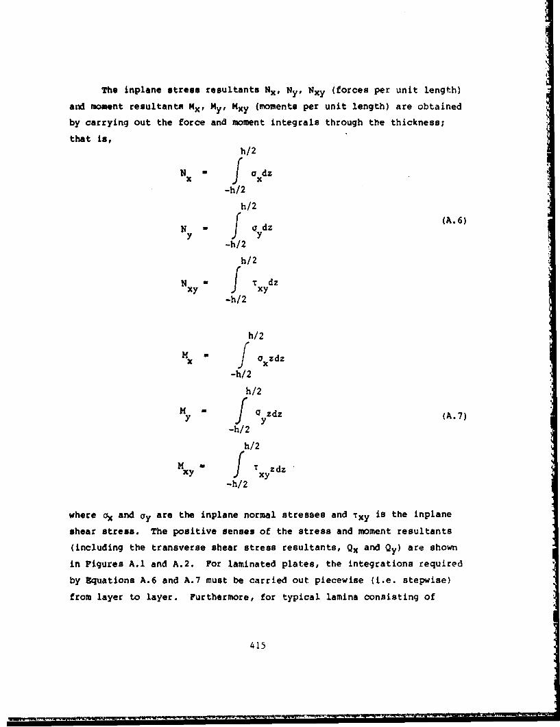
The inplane stress resultants Nx, Nye Nxy (forces per unit length)
and moment resultants Mx, My, Mxy (moments per unit length) are obtained
by carrying out the force and moment integrals through the thickness;
that is,h/2
N f adz
-h/2
h/2
N aydz (A.6)Ny.
-h/2
h/2
Nxy f Txydz-h/2
h/2MfMx a / x dz
-h/2
h/2
M f Q zdz (A.7)
-h/2
h/2
My Txyzdz
-h/2
where ax and Ocy are the inplane normal stresses and Txy is the inplane
shear stress. The positive senses of the stress and moment resultants
(including the transverse shear stress resultants, Qx and Qy) are shown
in Figures A.1 and A.2. For laminated plates, the integrations required
by Equations A.6 and A.7 must be carried out piecewise (i.e. stepwise)
from layer to layer. Furthermore, for typical lamina consisting of
415

Ny
OYj
p
N,.
k--y
NNy
Figure A.l. Positive stress resultants.
416

Z
Y000. MRy
mxy
Figure A.2. Positive omo.nt resultants.
417

parallel fibers imbedded in a matrix material, with the fibers lying at
an angle 0 with respect to the x-axis of the plate, the orthotropic
stress-strain relationships for the lamina must be transformed ten-
sorially to be consistent with the plate axes. The details of these
somewhat complicated calculations may be found elsewhere (cf. [A.I, A.2,
A.3]) and will not be elaborated upon here. Carrying out these calcu-
lations, one is able to relate the stress and moment resultants to the
midplane strains and curvature changes as follows:
Nx rA11 A12 A16'B 11 B12 B16 CxN A A A 'B B B
y 12 22 2 6 r 12 22 26 Y 0Nxy 16 26 66 "16 26 66 xy- - --- (A.8)M B B B D1I D D - X
x11 12 B16 1 1 12 16
1y 2 22 26' 12 22 26 yM B- D D DK,
Mxy B1 6 B2 6 B6 6 1D6 D2 6 D6 6 XY
where Aij, Bij and Dij are stiffness coefficients arising from integrals
of the following forms:
h/2
Aij f Cli dz-h/2
h/2
Bij f Cij zdz (A.9)
-h/2
h/2
Dii f Cfijz 2dz
-h/2
with Cij being constants which change from layer to layer during the
418

integrations. It is observed that, not only is the 6 x 6 stiffness
matrix of Equation A.8 symmetric, but the 3 x 3 submatrices Aij, Bij and
Cij are also symmetric.
It is important to understand the implications of the stiffness
coefficients in Equation A.8. The Bij coefficients cause coupling bet-
ween bending and stretching at the plate during transverse displacements.
As can be seen from the second of Equations A.9, these coefficients
vanish if the Cij are even functions of z. This occurs when the laminate
is symmetric (in thickness, fiber orientation and material properties)
with respect to the plate midplane.
Another type of coupling is seen by the existence of the A16, A2 6,
B16, B2 6, D1 6 , D2 6 coefficients. These coefficients indicate extension-
shear and/or bending-twisting coupling during the plate deformation.
This coupling vanishes for cross-ply lay-ups (i.e., fiber orientations
of adjacent lamina all lie along parallel or perpendicular axes).
Further discussions of coupling may be found in several excellent refer-
ences [A.l-A.5].
A.2. GOVERNING DIFFERENTIAL EQUATIONS
Consider a plate which, due to pressure components (Px, Py, q in
the x, y, z directions, respectively) and inplane stress resultants (Nx,
Ny, Nxy), has undergone bending. Sumning forces in the x, y and z di-
rections on a infinitesimal plate element yields the following equations
of equilibrium, respectively:
BN x +- + Pw aL X - o ax0
-a+ -y - Q -Y + P M 0 (A.10)
aQ x + nY + N -;2w + 2N -i2w + N 2Lw + q0
aX 3y x BX2 xy axay Y 3y2
419

Summing moments about axes parallel to the y and x coordlnates yields,
respectively,0 x + M :
aM am (A.11)Q +y ax ay
The transverse shear forces Qx and Qy, as well as the slopes aw/3x and
aw/ay, are typically small in the first two of Equations A.10. Taking
advantage of this, and substituting Equations A.11, Equations A.10
become3N 3N+ 14.2X + Px 0
axy a
aNxy + _3_.Y + Py M0
ax ay (A.12)a2M 32M 32M 32w-_ + 2- + + + N - + 2N1 -
ax2 axay y2 x2 3 xay
+ N -- + q- 0
Let us now consider each of the functions represented in Equations
A.12, except for w and the body forces, to be composed of two parts - an
initial part which exists before the onset of buckling, and an additional
part which is due to buckling. Let these two parts be denoted by the
superscripts "i" and "b". That is,
j bN - N + N , etc.
x x x(A.13)i b
H - M + M , etc.
420
WI. .NE==

It is assumed that the plate remains flat before buckling; i.e.,
bw - (A.14)
and further that no additional body forces are added during buckling;
% i.e.,
Px M Px Py W PY q o q (A.15)
At the onset of buckling, but before it takes place, Equations A.12 re-
duce to
BN
ax 3Y x
X + _Y + Py 0
x + 3 (A.16)
2M 321.1 a M2__._. + 2 -_. + __z + q 0
ax 2 Bx)y ay2
:;ubst.tuting Equations A.13, A.14 and A.15 into Equations A.12 and sub-
tracting Equations A.16 results in
b b3N 0
o Nb
+ - 0Bay (A.17)
b 32M Mb i2 3 2 N i a•+ xY Y4.I + N2 N xy •- + N =0
ax2 axay 3y2 x ,X aa Y ay2
wherein the three terms
N b _- + 2N b 2 + Nb 2w (A.18)
Ax2 xy axay Y ay 2
421

U,
are considered small relative to the I -ee terms of the third of)
Equations A.17, and have been droppe. .'. Because, in general, NxNxb and N y are functions of w, the three tems in expression (A.18)
are each nonlinear, and it is therefore i.iperative that they be dropped
in order for the buckling problem to be reasonably tractable.
Before proceeding further with the buckling equations, it is worth-
while to study further the meaning of Equations A.16 for the prebuckled
statp. Since w = 0, then A M Kx L 0. Substituting the pre-
buckled forms of equations A.4 and A.8 into Equations A.16 yields
[A [ - + A - +A 1 --3 1
3uv
L 11 ax 12 aY T16 T (A. 19a)
-L L u + A -- + A u26TY 6 6 y/J Px
+ A iL + A -- + A IV9126 ay 6\axy 6J
I .I±
2- B L + B __ + B v3x2 1 3x 12 ay 16( +ya2 i / a i
+ 2 B -IB + B + B + +q (.3x~y Lis ax 26 ay 6x ay/
rB U +B v- + +u' 0
By2 12 3x 22 Y 26" /
where, for simplicity, the subscript "o" has been dropped from the dis-
placements. For a symmetrically laminated plate, all the Bij are zero.
Then Equation A.19c yields 4 = 0. For given values of the initial,
tangential, body force components px and py and given values of u and v
422

and/or their derivatives (i.e., inplane stresses) on the plate boundaries,
one could solve Equations A.19a and A.19b for the displacement field
and i and, if desired, the corresponding initial stress field.
For an unsXnmtrically laminated plate, the Bjj are not all zero,
and the 3olutions for L and V can be substituted into Equation A.19c±
to determine what transverse pressure distribution q , together with
boundary moments and transverse forces, must be applied in order that
the plate remain flat. In the case that the initial, inplane stresses
(and strains) are constant or linearly varying with respect to x and y,
all terms except q1 vanish in Equation A.19c, with the result that no
initial, transverse pressure is needed for the plate to remain flat.
Equationo A.8 and A.11 show that constant initial strains give rise to
constant edge moments, and that linearly varying initial strains require
linearly varying moments and constant transverse shear forces for equi-
librium at the edges.
One convenient manner to represent the equilibrium equations
governing the buckled configuration is in terms of the three components
of inplane displacement. Substituting Equations A.4, A.5 and A.9 into
Equations A.17 yields the equations in matrix form as
L L Lu11 12 13 ( 0
L L L v 0 (A.20)21 22 23
L L (L -F) w 031 32 33
where the Lij are differential operators representing the plate
stiffness,
423

-•2 32 32L IA -t 2A -- +L A --11 11 3x2 16 axay 66 3y2
32 a2 32
L • A --L + -- A
22 22 ay2 2 6 Wxay 66 ax2
L D - + 4D + 2(D + 2D )33 11 aY4 16 Zx3ay 12 66 3x 2 3y 2
+ 4D at + D '26 9x3y 3 22 ay4 (A.21)
•22 22
LA -+ (A + -2 + A12 21 16 3x 2 12 6 6 a 26 3y 2
L a- 3 a3 03 0
L L -B 3B (B + 2B) B -
13 31 11 3x 3 16 ax2 ay 12 66 axay 2 26 3y3
a3 33 33 33
L L -B -3- (B + 2B 3B B23 32 16 3x3 12 66 ax2ay 26 3xay 2 22 3y3
and F is a differential operator representing the inplane loading,
32 •2 32
F + 2Ny +- N2-x ax2 xy 3x3y Y 3y 2
(A.22)
For simplicity, the superscripts "b" and "i" which were used in Equa-
tions A.17 have been dropped. In what follows, and in the main body of
the monograph, it will be regarded that u, v, w represent the (infini-
tesimally) small displacements of the plate during buckling, and that
Nx, Nxy, Ny represent the inplane forces which exist just before
buckling occurs. Equations A.20 are an eighth order set of partial
differential equations, similar in form to shell equilibrium equations
'cf. (A.6],pp. 32-34). Indeed, the coupling between bendirg and
stretching is responsible for raising the order from four to eight in
the present problem, just as the coupling of inextensional and membrane
theories raises the order from four to eight in the shell problem.
For symmetrically laminated plates Bij a 0 and the L and L13 23
operators in Equations A.21 are seen to vanish, and the inplane part of
424
St

the problem is uncoupled from the transverse part in Equation A.20. The
inplane part yields u - v - 0 in the buckled configuration, whereas the
transverse displacements are governed by
D -w- + 4D W + 2(D + 2D ) aW + 4D a4W + D --w
11 3X4 16 ax3ay 12 66 x2y2 26 axay3 22 ay4
-N-2w + 2N -w + N 32w (A.23)x X2 xy 3x3y Y 3y2
Equation A.23 is the same form as the buckling equation for a homogeneous,
anisotropic plate. The only difference is in how the stiffness coeffi-
cients Dij are calculated.
For symmetrically laminated cross-ply plates there is no coupling
between bending and twist, and D12' D 6= 0. Equation A.23 then special-
izes to
D -tw + 2(D + 2D ) + D a4w11 ax4 12 66 ax 2 Wy2 22 3y4
a2w a2W a2w (A.24)N 32w + 2N -3 + N
X aX2 xy BOY Y ay2
This is the same form as the buckling equation for a homogeneous, orthc_ -
tropic plate.
If, for example, a cross-ply plate of rectangular shape were
fabricated so that its edges were not parallel to the axes of material
orthotropy, then a coor6inate transformation to provide the proper
rotation of axes from the xy material coordinates of Equation A.24 to a, ,
set of x y coordinates parallel to the plate edges would result in a
form similar tc Equation A.23. This new form wuld have six stiffnessI I I I I
coefficients DII, D] 6 , D12, D6 6 , D2 6 , D2 2 , but they w.'uld be linear com-
binations of the four material coefficients D1 1 , D1 2 , D6 6 , D2 2 * It is
common in the literature to speak of a specially orthotropic plate when
425
~ ~ -. -

the orthotropic material axes and the rectangular plate edges are
parallel. However, this terminology will not be used in the present
work, for the word northotropic' should be used to describe a property of
the material, independent of the shape of the plate (e.g., rectangular)
or the orientation of a mathematically convenient coordinate system.
It must be remembered that the stress resultants Nx, Nxy and Ny
are positive in accordance with the directions shown in Figure A.l.
Particularly, compressive Nx or NY are negative quantities. Although,
for the sake of brevity, the stress resultants have been used in the
preceding derivation, for the sake of direct engineering application,
the stresses are used for the most part elsewhere in this monograph.
For some types of buckling problems where bending-stretching
coupling exists it may be desirable to use the inplane stress resultantsb b bgenerated during buckling (i.e., NX , Nb , Nxy ) instead of the inplane
displacements (u, v) which occur. It is then usually convenient to re-
present the inplane stress resultants by an Airy stress function (0),
with the functions defined by the equations
N b a 2ý
X 2x •y2
N b - 32$ (A.25)
Nb 2xy 3•xy
If Equations A.25 are substituted into the first two of Equations A.17,
it is seen that the latter are identically satisfied. However, since the
problem is no longer expressed in terms of inplane displacements, it
becomes necessary for the inplane stresses to satisfy the inplane equation
of compatibility
'16
J .. .... . ... ... . . ....... . .. ..

a2 r0 + 2C 0 o 2 y O0j2 x + - • 0
ay2 3X2 ax~y (A. 2 6)
0 0 0where the strains (ex , Cy , Yxy ) are those additional ones arising
during buckling, but the superscript "b" is dropped for simplicity.
To utilize Equation A.26, Equation A.8 must be at least partially
inverted. Rewriting Equation A.8 in the symbolic form
[A [B] DJ[: (A.27)
0where N, M, c. and K are 3 x 1 subvectors and A, B and D are the 3 x 3
submatrices delineated in Equation A.8. Multiplying through the first
-if the two submatrix equation: of Equations A.27 Dy A-, and solving for e
yields
° 0. A-1N -0A- BY (A.28)
Substituting Equation A.28 into the second of Equations A.27 results in
M - BA-1N - (D-BA' 1 B)K (A.29)
and Equations A.28 and A.29 may be written in matrix form (A.4] as
L0i [A* Bi]where DJ {(A.30)
where B*T is the transpose of the Be submatrix, and where
A A-, B -A B D- D-BA B (A. 31)
While A* and D* are symmetric submatrices, B is, in general, not sym-
m.tric. Substituting Equations A.5, A.25 and A.30 into Equation A.26
yields
427

* * 4 * * at + A -
A -- 2A + (2A + A ) 2A - + A22 3X4 26 ;x3;y 12 66 ;x 2 ay 2 16 axay 3 11 ;y4
* w * *) •w * * a•w
- B -- + (B - 2B (B + - 2B )
21 aX4 61 26 ax3ay 11 22 66 ax2 3y2 (A.32)
* * � 4 w *a 4 w+ (B - 2B ) -B -- 0
62 16 ;Xay 3 12 ;y4
for the compatibility equation in the buckled state. Similarly, sub-
stituting Equations A.5, A.25 and A.30 into Equations A.17 yields
B -* + (2B -B ) 6 + (B + B -2B ) 34
21 3x4 26 61 3x3ay 11 22 66 ;x 2 ay 2
* ' ~~* 4 w * •
* (2B -B ) 0+B +D -+4D16 62 axay 3 12 ay4 11 a•X 16 ax3ay
* * a w * at w * •w-
+ 2(D + D ) + 4D + D * (A.33)12 66 ax 2 aY2 26 axay 3 22 ay4
S3w + 2N + N 3"X ax 2 XY y Y ay2
for the equilibrium equation in the buckled state. As in Equations
A.22, A.23 and A.24, the superscript "i" has been dropped from Nx, Ny
and Nxy in Equation A.33, but it must be remembered that these inplane
Stress resultants exist just before buckling occurs, whereas 0 is re-
lated by Equations A.25 to the additional stress resultants generated by
the buckled mode shape. Equations A.32 and A.33 form a set of differ-
ential equations of eighth order.
For symmetrically laminated plates Bij - 0, and Equations A.32 and
A.33 uncouple. Equation A.32 becomes the anisotropic, stress function
form of the compatibility equation for plane elasticity, and Equation
A.33 reduces to Equation A.23.
428

A.3. BOUNDARY CONDITIONS
The classical, bifurcation buckling problem for a laminated
composite plate requires satisfying the governing differential equations
(Section A.2.) and the boundary (or edge) conditions. Both sets of
equations are homogeneous, leading to an eigenvalue problem for the
eigenvalues (buckling loads) and eigenfunctions (mode shapes). Con-
sistent with the eighth order sets of differential equations which must
be satisfied, four boundary conditions must be applied to each edge of
the plate. The classical conditions are
bun 0 or Nn 0 (A. 34a)
bu = 0 or N b= 0 (A.34b)t ~nt
bb __n_
w = 0 or Vb = Q + nt 0 (A.34c)n n at
aw 0 or Mb 0 (A. 34d)an n
In the above equations the subscripts n and t denote the coordinates
normal and tangential to the boundary. The function Qn + aMnt/at is the
wellknown Relvin-Kirchhoff "edge reaction" which must be nullified at a
free edge. In addition, at a free rectangular corner (the intersection
of two free edges), the point condition Mnt = 0 must be satisfied. The
superscript "b" is added here to the generalized forces to avoid
confusing them with the inplane forces (e.g., N , Ni, N existing
just before buckling.
Equations A.34 may be used to represent any form of "simple" edge
condition (e.g., clamped, simply supported, free). More general
boundary conditions which are applicable to edges having elastic con-
429
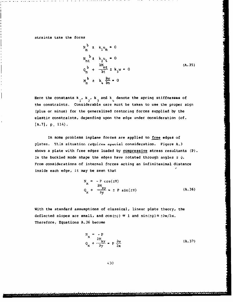
straints take the forms
bN ± k u 0n In
N n t k2 t-0
b + 'Mnt (A.35)+ -± k~w 0
b awm :t k 1---0n 4 an- O
Here the constants k 1, k, k and k denote the spring stiffnesses ofI 2 3 14
the constraints. Considerable care must be taken to use the proper sign
(plus or minus) for the generalized restoring forces supplied by the
elastic constraints, depending upon the edge under consideration (cf.
(A.7], p. 114).
In some problems inplane forces are applied to free edges of
plates. This situation zequirerb 6euial consideration. Figure A.3
shows a plate with free edges loaded by compressive stress resultants (P).
In the buckled mode shape the edges have rotated through angles ± P.
From considerations of internal forces acting an infinitesimal distance
inside each edge, it may be seen that
N - P cos(±'')
Q + -- • P sin(±_+) (A.36)ay
With the standard assumptions of classical, linear plate theory, the
deflected slopes are small, and cos(±t) - 1 and sin(±f)lz ±w/ax.
Therefore, Equations A.36 become
N = -P
Qx + am = w (A.37)x y ax
430
S...~~. .I . . . . . ...... . ... . . .. .

x
- _-
X "-
Q+
Figure A.3. Inplane stress resultants (P) applied to f;ee edges.
431

which are the proper conditions to use in solving the problem. Similar
conditions exist at free edges y = constant.
In applying the boundary conditions it is useful to have explicit
expressions for the various functions used in Equations A.34. For the
displacement formulation of the problem they are obtained from Equations
A.4, A.5, A.8, A.11 and A.34c.
N =A 2+A +v A + 32Nx 1 ax 12 aY I C T
B 2w --2 B a2w (A.38a)
-B a2w- B - - 2B N11 ax2 12 16 3x3y
NL + -+A Lv+ A 3)
Y = x+12 22 aY 260ax(A.38b)
B 2-w - B 2-w - 2B a2w12 aX2 22 ay 2 26 DXDY
NY A u + v A Lv + _~ Ay. a av rax au\Nxy A -+Ax
16 26 Y 66' au)?32 w 2 (A.38)
-B --- - B - - 2B D216 9x 2 26 ay2 66 BXZy
M u + v +B dv +u•-B •+B ~+ +. uX a1 x 12 3Y 166aX a
D 2w -D w a2w (A.38d)- -- D --- 2D-D 3X2 12 ay 2 16 BxOy
M =B -u+B -+B ++BY 12 22 26 L ax 3y'
a2 2 w w 2 w (A. 38e)
-D D - - 2D a2w1z aX2 22 ay 2 26 axay
432

M - B 2-+ B -v+ B ax aKy 16~ ax 26" 3 Y 6 6('x + /
2ýw - 2 w - 2w (A.38f)-D -- D -- -2D --
16 ax2 26 ay2 66 3xaY
Qx " 32U- + 2B a2u + B a2u + B L2 v
11 ax2 16 axay 66 ay2 16 ax2
+ (B + B v 2 v 3w2 6 -y + B D - (A.38g)12 66 y 26 ay2 11 x 3
- 3D -- - (D + 2D ) - D Iw
16 3X2ay 12 66 ýxay2 26 ;y3
Qy -B -2u + (B + B ) -2+ -+B •u-+16 ax2 12 66 3X3Y 26 ay2 66 3x2
a2v 32v a3w __3w_
+ 2B -L + B -- D -- (D + 2D ) (A.38h)26 axxy 22 3y2 16 ay3 12 66 ax2ay
a3w 3- 3D -- D -
26 aXay 2 22 ay3
a2 2 u a2u 2
V -B L-+ 3B 2- + 2B 2- + B -2
x 11 ax2 16 xy 66 Wy2 16 ax2
+ a+2 2v a2 3w+(B +-2B + 2B --- D -- (A.38i)
12 66 ax3Y 26 Wy2 11 ax 3
-4 3w 33w _3w
- 4D -- - (D + 4D ) -2D a3,16 ax2ay 12 66 axay 2 2 6 y 3
32 U I2u a2u ;2vV 2B -- +(B +2B ) ''-B -+ 2B _
y 16 3x3 12 66 xa + B +6 2B6 x26 ay2 66 ax2
a2v a2v a3w _____
+ 3B -3 + B L - 2D (D + 4D aw (A.38j)26 3xaY 22 ay2 16 ax3 12 66 ax2 ;y
a3w 3-4D -D -D
26 axay 2 22 ay3
433

For the stress function (and transverse displacement) formulation of the
problem, the inplane stress resultants are given by Equations A.25; the
other useful quantities are obtained from Equations A.5, A.1l, A.25,
A.30 and A.34c.
M - ( -* a2 B *-+B -3
x 21 ax2 61 axay 11 By2
* a2 W * a2 32(A.w39a)+ D -+2D -+ D11 ax 2 16 aXaY 12 ay2 /
M * - 2 -- B * 20+ B *-2Y \22 ax2 62 axay 12 ay 2
+ D * a 2 w •* a2w *2 w+ DA*
9b)
12 ax 2 26 axay 22 ay2)
H -BB * ;20 -_B - +B2 * -20
- 26 ax 2 66 axay 16 ay 2 (A.39c)
a W a2w * a 2w16 ax 2 66 dxay 26 9y2
* 3 ** a30 * *Q JB 2- (B * B - +(B -B)
L21 ax3 2.6 61 ax2ay 11 66 axay2
"+ B a3 * • + 3D * 3 W(A.39d)
16 ay 3 11 ax 3 16 ax2ay
• * a3w * a3wl"+ (D *+ 2D *) a-- + D * 3
12 66 axay 2 26 ay3 J
- F* B• * 34* * a3
QY -[B -- + (B - B + (B - B )26 3 22 66 3ay 16 62 axay2
* a33 * a3W * a3w"+ B - + D - + (D + 2D ) (A.39e)12 ay 3 16 ax 3 12 66 ax2ay
" 3D '3w + D a 3w
26 axay2 22 ay3L
434

I.I
*~3 [;30*[B2 *~ -B) +B -7Bx3 2 6 61 1x21y + I 66 ýxay2
, •3 * a•3 w • 3w'
+ 2B +b -- + 4D (A.39f)1 6 By3 11 DX3 16 3x2ay (3
, 3 W 3w+ (D12 + 4D ) + 2D 2
1? 66 8xay2 26 ay 3 J
[ 83 * * 3wV - B -+(B .2B + +(2B -B)L 26 33 22 66 ;x2ay 16 62 3x3y2
B* + 2D 3W+ (D + 4D ) 3w (312 ;y 3 16 3x3 12 66 ax2ay (A.39g)
+ 4D + D -26 axay2 22 ay3
For non-rectangular plates other forms of un, ut, N1n, Nnt, Mn,
nt, Qn and Vn are needed. These may be obtained by using the vector and
tensorial transformation formulas generally available in the standard
texts dealing with the theory of elasticity and plate theory (cf., (A.8,
A.9]), together with Equations A.38 or A.39.
For :-igetric laminates the bending-stretching coupling disap-
pears, and Bij a 0 in Equations h.38 and A.39. For cross-ply plates
having fibers parallel to the x and y axes, D 12- D 16= 0 in Equations
A.38 and A.39.
A.4. ENERGY FUNCTIONALS
The total potential energy of a plate (V) while in equilibrium in
a displaced buckling mode is given by
S- VS + + VBS + V1 (A.40)
43•)
iR
.........................-........

where Vs, VB and VBS are the strain energies due to stretching, bending
and bending-stretching coupling, respectively, and VL is the potential
due to the applied inplane forces.
Formulation of the buckling problem in terms of the potential
energy is useful for at least the following two reasons:
(I) Variational principles may be applied to derive the
differential equations of equilibrium and a mathematically
consistent set of boundary conditions
(2) The buckling problem may be directly solved by energy methods,
such as the widely used Ritz method.
The strain energy in a deformed plate is
V =(a + 0 e + T y )d(Vol) (A. 41.)x x y y xy xy
Vol
where the stresses and strains are those used previously in Section A.1,
and the integration is carried out over the volume of the plate. Sub-
stituting into Equation A.41 the stress-strain relationships for each
lamina, carrying out the tensorial transformations required to express
the stresses and strains in terms of a single plate coordinate systemI. (x, y), applying the kinematic conditions of Equations A.3, A.4 and A.5,6.2
and integrating over the thickness layer by layer yields [A.4]:
V. f [A \ /+2A 12Av+ A2 (,)S 2 [A 12 ax ay 22
+ 2A - + + 2A -- + 2(A.42a)
a ax 26 a y zy
"+ A ('u + dxdy66\Y 6
63
r'430
I P s

I
VBS 2 A 1 1 ax 2 12 \iY ax2 Xa 2
22 axa2 6~ ax aX(A 4b
_ 2WýU a 2u w2 iV L2w W u 9 2 ,j
4. B + 2B (_ + 2 1--2 yJO 22 3Y 3y2 16 3y 2 ax x2 ax axyyax ax(A. 42b)
+2B (a 2 v a2w + 2 1_-V 32w26 aY 3y2W + x 3y2 ay x y/
"a u + v a2w+4B L -+ - Y dxdyg~ 66 (3x ay Y xa
1 fja 1 a2w /L 2204B 2 1 2 12 ax 2 y 2 22 y2
+24D w 2w a2w 32 w (A.42C)
16 9x2 X3ay 26 ay2 axay
+ 4D - 2w )2 ] dxdy
where the Aij, Bij and Dij are the plate stiffness coefficients used
previously in Equation 8 and the integrals are taken over the area of the
plate.
For a symmetric laminate, Bij a 0 and consequently the strain
energy due to bending-stretching coupling (VBS) vanishes. Then Equation
A.42c represents the entire strain energy caused by bending (i.e.,
changes in curvature), and is of the same form as found for homogeneous,
anisotropic plates [A.1]. For a cross-ply laminate, with fibers parallel
to the x arn] y coordinates, D 16 D 26- 0.
The potential energy due to the initial inplane loads is
VL Nxx + N cy + Nxy xy dxdy (A.43)
A
437

!z"where x' , C; and Yxy! are the midplane strains caused by a transversedisplacement field (w). These are given by (A.9]
Lawx-
'y " "?W7 (A. 44)
Substituting Equations A.44 into A.43 results in
NY 1ayi/+ 2N w- -- dxdy (A.45)2 [)y N x 3y
438

A.5. REFERENCES FOR APPENDIX
A.I. Lekhnitskii, S. G., Anisotropic Plates, Second Edition, translated
from the Russian by S. W. Tsai and T. Cher.n, Gordon and Breach
Science Publishers, Inc., 534 pp. (1968).
A.2. Ashton J. E., Halpin, J. C. and Petit, P. H., Primer on CompositeMaterials: Analysis, Technomic Publishing Co., Inc., 124 pp.
(1969).
A.3. Jones, R. M., Mechanics of Composite Materials, Scripta Book Co.,Washington, D.C., 355 pp. (1975).
A.4. Ashton, J. E. and Whitney, J. M., Theory of Laminated Plates,
Technomic Publishing Co., Stamford, Conn., 153 pp. (1970).
A.S. Reissner, E. and Stavsky, Y., "Bending and Stretching of CertainTypes of Heterogeneous Aeolotropic Elastic Plates", Trans. ASME,
Journal of Applied Mechanics, Vol. 9, pp. 402-408 (1961).
A.6. Leissa, A. W., Vibration of Shells, NASA SP-288, U.S.Govt.Printing Office, 428 pp. (1973).
A.7. Leissa, A. W., Vibration of Plates, NASA SP-160, U.S.Govt.Printing Office, Washington, D.C., 353 pp. (1969).
A.8. Timoshenko, S. P. and Goodier, J. N., Theory of Elasticity, Third
Edition, McGraw-Hill Book Co., 567 pp. (1970).
A.9. Timoshenko, S. and Woinowsky-Krieger, S., Theory of Plates andShells, Second Edition, McGraw-Hill Book Co., 580 pp. (1959).


