A1120/40 Polyphase Phase Meter - MWA Technology · A1120/40 Meter 1 Elster Metering Limited - M181...
21
A1120/40 Polyphase Phase Meter End User's Guide M181 001 6A 12.2011
Transcript of A1120/40 Polyphase Phase Meter - MWA Technology · A1120/40 Meter 1 Elster Metering Limited - M181...

A1120/40
Polyphase Phase Meter
End User's Guide
M181 001 6A
12.2011


A1120/40 Meter 1 ________________________________________________________________________________________________________________________________________________
Elster Metering Limited - M181 001 6A - 12.2011
ABOUT THIS DOCUMENT
This document is intended as a guide to help Suppliers of Elster Metering Systems A1120 Meters produce User Manuals for End Users.

2 A1120/40 Meter ___________________________________________________________________________________________________________________________________
Elster Metering Limited - M181 001 6A - 12.2011
Example text you may wish to use:-
ABOUT YOUR METER
Your Elster A1120 Meter has been chosen by your Service Provider to measure the amount of energy flowing through your installation. Some features described in this manual may not be exactly the same as your particular installation. For instance information viewed on the Liquid Crystal Display (LCD) may not be exactly the same as shown in this manual. Rest assured, the basic operation is exactly the same and you should have no difficulty in following the 'step by step' guides described in this manual.

End User's Guide 3 ___________________________________________________________________________________________________________________________________
SAFETY
SAFETY
To prevent fire or shock hazard, never expose the meter to water
Parts of the internal circuits of your meter are connected to phase voltages. These circuits are highly dangerous if they are touched in any way, and could result in an electric shock or fatality. For this reason all internal circuits are protected by covers with seals. You should 'never' attempt to remove the seals of the Main Meter Cover or Terminal Cover.
Liquid Crystal Display
Liquid crystals are toxic. If the display of your meter is damaged you should avoid contact with any liquid that may be seeping from it.
If the liquid makes contact with your skin, wash the affected area thoroughly with running water and soap.
If liquid crystals get into your eye(s), flush the eye(s) with clean water for at least 15 minutes.
If liquid crystal is swallowed, flush your mouth thoroughly with water, drink large quantities of water to induce vomiting.
Immediately Seek Medical Advice.
Report the damage to your Service Provider
4 A1120/40 Meter ___________________________________________________________________________________________________________________________________
Elster Metering Limited - M181 001 6A - 12.2011
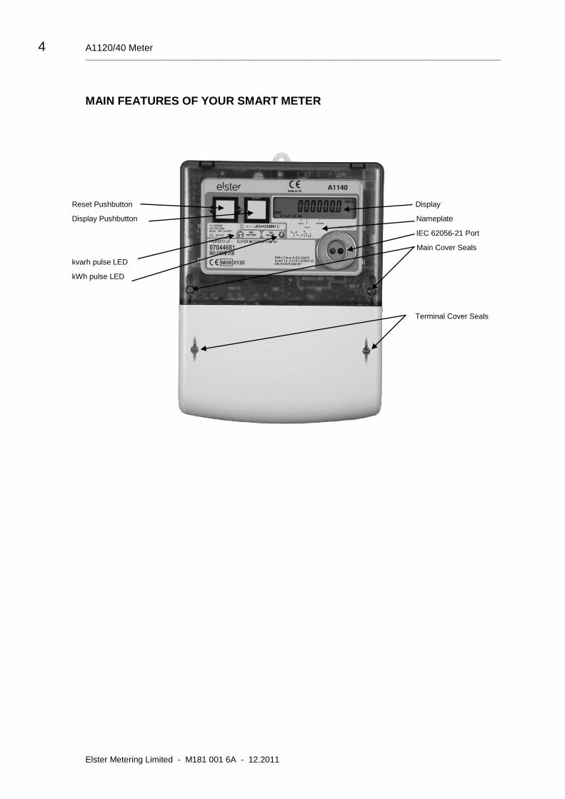
MAIN FEATURES OF YOUR SMART METER
Reset Pushbutton Display
Display Pushbutton Nameplate
IEC 62056-21 Port
Main Cover Seals
kvarh pulse LED
kWh pulse LED
Terminal Cover Seals
End User's Guide 5 ___________________________________________________________________________________________________________________________________
HOW TO CHECK YOUR METER IS WORKING
As your installation generates electricity, a display (similar to the
one shown opposite) will increment, allowing you to calculate
exactly how much electricity you are generating over a given period
of time.
When the Red kWh Energy Indicator is 'Flashing' the generating system is producing electricity. The
faster it 'Flashes' the more electricity you are producing. If the indicator is permanently 'On', no
electricity is being produced.
Energy Generated Example:
Cumulative Energy Register Reading - 013862.6kW
Energy Reading After 24 Hours - 013868.7kW
Energy Produced Over 24 Hour Period - 6.1kW
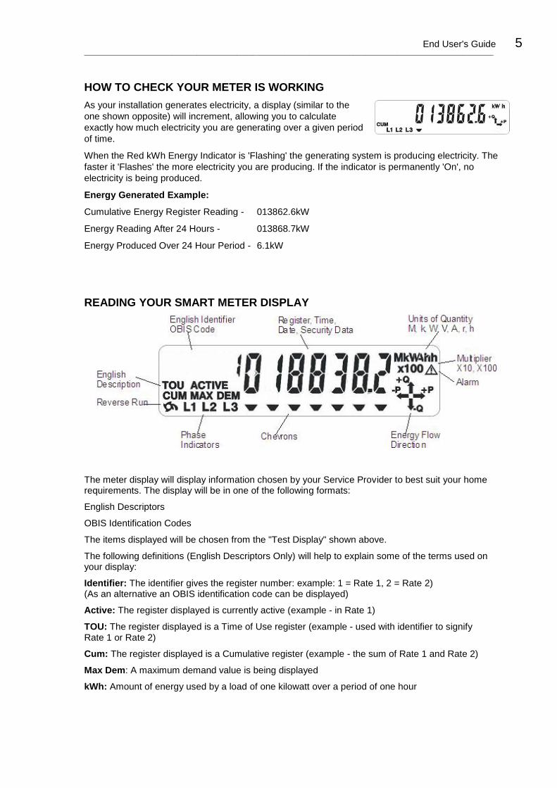
READING YOUR SMART METER DISPLAY
The meter display will display information chosen by your Service Provider to best suit your home requirements. The display will be in one of the following formats:
English Descriptors
OBIS Identification Codes
The items displayed will be chosen from the "Test Display" shown above.
The following definitions (English Descriptors Only) will help to explain some of the terms used on your display:
Identifier: The identifier gives the register number: example: 1 = Rate 1, 2 = Rate 2) (As an alternative an OBIS identification code can be displayed)
Active: The register displayed is currently active (example - in Rate 1)
TOU: The register displayed is a Time of Use register (example - used with identifier to signify Rate 1 or Rate 2)
Cum: The register displayed is a Cumulative register (example - the sum of Rate 1 and Rate 2)
Max Dem: A maximum demand value is being displayed
kWh: Amount of energy used by a load of one kilowatt over a period of one hour
6 A1120/40 Meter ___________________________________________________________________________________________________________________________________
Elster Metering Limited - M181 001 6A - 12.2011
Display Mode
The display has two modes of operation, Default Mode and Utility Mode. Up to 40 displays can be made available for each mode of operation.
Default Mode
The Default Mode can operate in two ways, Auto-cycle or single step.
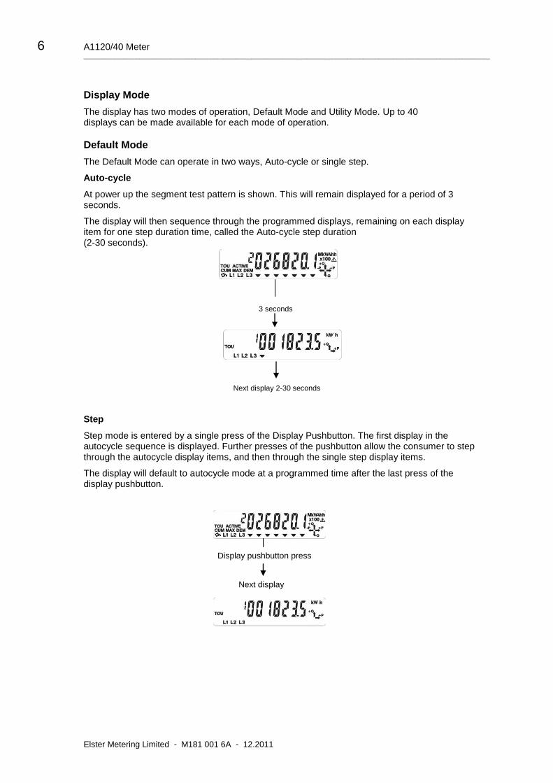
Auto-cycle
At power up the segment test pattern is shown. This will remain displayed for a period of 3 seconds.
The display will then sequence through the programmed displays, remaining on each display item for one step duration time, called the Auto-cycle step duration (2-30 seconds).
3 seconds
Next display 2-30 seconds
Step
Step mode is entered by a single press of the Display Pushbutton. The first display in the autocycle sequence is displayed. Further presses of the pushbutton allow the consumer to step through the autocycle display items, and then through the single step display items.
The display will default to autocycle mode at a programmed time after the last press of the display pushbutton.
Display pushbutton press
Next display

End User's Guide 7 ___________________________________________________________________________________________________________________________________
Utility Mode
The Reset button may be sealed in which case you cannot access Utility Mode.
If the Reset button is not sealed, Utility mode is entered by pressing the Reset Pushbutton.
‘Utility’ appears on the display.
Single presses of the Display pushbutton will then step through the Utility displays. The display will default to Autocycle Mode at a programmed time after the last press of the Display Pushbutton, or if the Reset Pushbutton is again pressed. Short press Reset Pushbutton
Press Display Pushbutton
Next display
Displays with English Descriptors
Chevrons/Identifiers/Descriptors
The chevrons on the display have the following meaning: Identifiers
Description
1 2 3 4 5 6 7
Import Security
Export
The display identifiers give a description of the main register displayed.
Displays with OBIS Codes
The OBIS code gives a description of the main register displayed. OBIS Code
Chevron 7 indicates the register is active.
Examples of displays and a full list of displays are given towards the back of this manual.
Chevron
1 Import
2 Export
3 -
4 Security
5 -
6 -
7 -
Identifiers
1 Rate 1
2 Rate 2
Descriptors
TOU Time of Use
Active Active Rate
CUM Cumulative
MAX DEM Maximum Demand

8 A1120/40 Meter ___________________________________________________________________________________________________________________________________
Elster Metering Limited - M181 001 6A - 12.2011
Display Indicators
Energy Direction Indicators
System Reverse Run Indicator
Phase Failure Indication
Error/Alarm
Communications Indication
When communications are taking place the following indicator is displayed.
o Optical communication
r RS232 Communication

End User's Guide 9 ___________________________________________________________________________________________________________________________________
DISPLAYS
English Displays OBIS Displays
Cumulative
Customer Defined (1-2)
Rising Demand (Export)
Maximum Demand (1-4)
Maximum Demand (1-4) Date Time
Cumulative Maximum Demand (1-4)
Time of Use (1-8)
A1120/40 Displays

10 A1120/40 Meter ___________________________________________________________________________________________________________________________________
Elster Metering Limited - M181 001 6A - 12.2011
English Displays OBIS Displays
Historical
Security (Reverse Run Event Count)
Instrumentation (Phase A Voltage)
Dial Test
Communications Indicators Optical Remote RS232
End of Billing (Change of Season) End of Billing (Internal Battery Fail)
Error (Power Fail Data) Error (Internal Battery Fail)
CT (Scalar) CT (Ratio)
External Registers
A1120/40 Displays (continued)

End User's Guide 11 ___________________________________________________________________________________________________________________________________
Description Units OBIS Display Code English Display
Note 1** Identifier Chevron Index
Segment Test - - - - -
Current Time - 0.9.1 - - -
Current Date - 0.9.2 - - -
Cumulative
Total Import kWh kWh 1.8.0 CUM 1 -
Total Export kWh kWh 2.8.0 CUM 2 -
Q1 kvarh kvarh 5.8.0 CUM - 1
Q2 kvarh kvarh 6.8.0 CUM - 2
Q3 kvarh kvarh 7.8.0 CUM - 3
Q4 kvarh kvarh 8.8.0 CUM - 4
kVAh 1 kVAh D.8.0 CUM - -
kVAh 2 kVAh E.8.0 CUM - -
Total Import kWh Phase A * kW 21.8.0 CUM 1 A
kWh Phase B * kW 41.8.0 CUM 1 B
kWh Phase C * kW 61.8.0 CUM 1 C
Total Export kWh Phase A * kW 21.8.0 CUM 2 A
kWh Phase B * kW 41.8.0 CUM 2 B
kWh Phase C * kW 61.8.0 CUM 2 C
Customer Defined 1 ** A.8.0 CUM - Cd 1
Customer Defined 2 ** B.8.0 CUM - Cd 2
Rising Demand
Total Import kW kW 1.4.0 DEM 1 -
Total Export kW kW 2.4.0 DEM 2 -
Q1 kvar kvar 5.4.0 DEM - 1
Q2 kvar kvar 6.4.0 DEM - 2
Q3 kvar kvar 7.4.0 DEM - 3
Q4 kvar kvar 8.4.0 DEM - 4
kVA 1 kVA D.4.0 DEM - -
kVA 2 kVA E.4.0 DEM - -
Total Import kWh Phase A * kW 21.4.0 DEM 1 A
kWh Phase B * kW 41.4.0 DEM 1 B
kWh Phase C * kW 61.4.0 DEM 1 C
Total Export kWh Phase A * kW 21.4.0 DEM 2 A
kWh Phase B * kW 41.4.0 DEM 2 B
kWh Phase C * kW 61.4.0 DEM 2 C
CD 1 ** A.4.0 DEM - Cd 1
CD 2 ** B.4.0 DEM - Cd 2
Cumulative MD (1-4)
Total Import kW kW 1.2.(1 - 4) CUM MAX DEM - 1 - 4
Total Export kW kW 2.2.(1 - 4) CUM MAX DEM - 1 - 4
Q1 kvar kvar 5.2.(1 - 4) CUM MAX DEM - 1 - 4
Q2 kvar kvar 6.2.(1 - 4) CUM MAX DEM - 1 - 4
Q3 kvar kvar 7.2.(1 - 4) CUM MAX DEM - 1 - 4
Q4 kvar kvar 8.2.(1 - 4) CUM MAX DEM - 1 - 4
kVA 1 kVA D.2.(1 - 4) CUM MAX DEM - 1 - 4
kVA 2 kVA E.2.(1 - 4 CUM MAX DEM - 1 - 4
1 - 4 CD 1 ** A.2.(1 - 4) CUM MAX DEM - 1 - 4
1 - 4 CD 2 ** B.2.(1 - 4) CUM MAX DEM - 1 - 4
Maximum Demand (1-4)
1 - 4 Import kW kW 1.6.(1 - 4) MAX DEM - 1 - 4
1 - 4 Import Time - 1.6.(1 - 4) MAX DEM - 1 - 4
1 - 4 Import Date - 1.6.(1 - 4) MAX DEM - 1 - 4
1 - 4 Export kW kW 2.6.(1 - 4) MAX DEM - 1 - 4
1 - 4 Export Time - 2.6.(1 - 4) MAX DEM - 1 - 4
1 - 4 Export Date - 2.6.(1 - 4) MAX DEM - 1 - 4
1 - 4 Q1 kvar kvar 5.6.(1 - 4) MAX DEM - 1 - 4
1 - 4 Q1 Time - 5.6.(1 - 4) MAX DEM - 1 - 4
1 - 4 Q1 Date - 5.6.(1 - 4) MAX DEM - 1 - 4
1 - 4 Q2 kvar kvar 6.6.(1 - 4) MAX DEM - 1 - 4
1 - 4 Q2 Time - 6.6.(1 - 4) MAX DEM - 1 - 4
1 - 4 Q2 Date - 6.6.(1 - 4) MAX DEM - 1 - 4
1 - 4 Q3 kvar kvar 7.6.(1 - 4) MAX DEM - 1 - 4
1 - 4 Q 3 Time - 7.6.(1 - 4) MAX DEM - 1 - 4
1 - 4 Q3 Date - 7.6.(1 - 4) MAX DEM - 1 - 4
1 - 4 Q4 kvar kvar 8.6.(1 - 4) MAX DEM - 1 - 4
1 - 4 Q4 Time - 8.6.(1 - 4) MAX DEM - 1 - 4
1 - 4 Q4 Date - 8.6.(1 - 4) MAX DEM - 1 - 4
1 - 4 kVA 1 kVA D.6.(1 - 4) MAX DEM - 1 - 4
1 - 4 kVA 1 Time - D.6.(1 - 4) MAX DEM - 1 - 4
1 - 4 kVA 1 Date - D.6.(1 - 4) MAX DEM - 1 - 4
1 - 4 kVA 2 kVA E.6.(1 - 4) MAX DEM - 1 - 4
1 - 4 kVA 2 Time - E.6.(1 - 4) MAX DEM - 1 - 4
1 - 4 kVA 2 Date - E.6.(1 - 4) MAX DEM - 1 - 4
1 - 4 CD 1 ** A.6.(1 - 4) MAX DEM - 1 - 4
1 - 4 CD 1 Time ** A.6.(1 - 4) MAX DEM - 1 - 4
1 - 4 CD 1 1 Date ** A.6.(1 - 4) MAX DEM - 1 - 4
1 - 4 CD 2 ** B.6.(1 - 4) MAX DEM - 1 - 4
1 - 4 CD 2 Time ** B.6.(1 - 4) MAX DEM - 1 - 4
1 - 4 CD 2 Date ** B.6.(1 - 4) MAX DEM - 1 - 4
Display Table

12 A1120/40 Meter ___________________________________________________________________________________________________________________________________
Elster Metering Limited - M181 001 6A - 12.2011
Description Units OBIS Display Code English Display
Note 1** Identifier Chevron Index
TOU (1-8)
1 - 8 Import kWh kWh 1.8.(1 - 8) TOU - 1 - 8
1 - 8 Export kWh kWh 2.8.(1 - 8) TOU - 1 - 8
1 - 8 Q1 kvarh kvarh 5.8.(1 - 8) TOU - 1 - 8
1 - 8 Q2 kvarh kvarh 6.8.(1 - 8) TOU - 1 - 8
1 - 8 Q3 kvarh kvarh 7.8.(1 - 8) TOU - 1 - 8
1 - 8 Q4 kvarh kvarh 8.8.(1 - 8) TOU - 1 - 8
1 - 8 kVAh 1 kVAh D.8.(1 - 8) TOU - 1 - 8
1 - 8 kVAh 2 kVAh E.8.(1 - 8) TOU - 1 - 8
1 - 8 CD 1 ** A.8.(1 - 8) TOU - 1 - 8
1 - 8 CD 2 ** B.8.(1 - 8) TOU - 1 - 8
External Registers
Register Set 1 (1-4) - User selectable Cum - S1 - (1 - 4)
Register Set 2 (1-4) - User selectable Cum - S2 - (1 - 4)
Register Set 3 (1-4) - User selectable Cum - S3 - (1 - 4)
Security
Program Event Count - C.2.0 - 4 1
Program Event Time - C.2.0 - 4 1
Program Event Date - C.2.0 - 4 1
CT Ratio Change Count - C.72.0 - 4 2
CT Ratio Change Time - C.72.0 - 4 2
CT Ratio Change Date - C.72.0 - 4 2
Phase Fail Event Count - C.54.0 - 4 3
Phase Fail Event Time - C.54.0 - 4 3
Phase Fail Event Date - C.54.0 - 4 3
Power Fail Event Count - C.7.0 - 4 4
Power Fail Event Time - C.7.0 - 4 4
Power Fail Event Date - C.7.0 - 4 4
Rev Run Event Count - C.53.0 - 4 5
Rev Run Event Time - C.53.0 - 4 5
Rev Run Event Date - C.53.0 - 4 5
End Billing Count - 0.1.0 - 4 7
End Billing Time - 0.9.6 - 4 7
End Billing Date - 0.9.7 - 4 7
Main Cov RemCount - C.70.0 - 4 8
Main Cov Remove Time - C.70.0 - 4 8
Main Cov Remove Date - C.70.0 - 4 8
Term Cov Rem Count - C.71.0 - 4 9
Term Cov Remove Time - C.71.0 - 4 9
Term Cov Remove Date - C.71.0 - 4 9
Est Battery Life Remain - C.6.0 - 4 10
In Service Hours - C.8.0 - 4 11
Active Tariff CRC - C.80.1 - 4 CrC1
Deferred Tariff CRC - C.80.4 - 4 CrC4
CT Ratio - 0.4.2 4 Ct
EOB Events (All Meters) Code (HEX) Display
Program Date or Midnight 01 rESEt
Change of Season 02 rESEt
Deferred Tariff 04 rESEt
Serial Port Command 08 rESEt
Optical Port Command 10 rESEt
Billing Pushbutton Press 20 rESEt
CT Programming Event 40 rESEt
Battery Fail 80 rESEt
Meter Errors -
Power fail data - FF 0040 Error 0040
Period backup data error - FF 0080 Error 0080
ROM checksum error - FF 0100 Error 0100
I2C Bus error - FF 0200 Error 0200
Internal battery life exceeded
- FF 0400 Error 0400
Internal battery fail - FF 0800 Error 0800
Display Table (continued)

End User's Guide 13 ___________________________________________________________________________________________________________________________________
Description Units OBIS Display Code English Display
Note 1** Identifier Chevron Index
Historical (Most recent only)
Total Import kWh kWh 1.8.0.1 CUM - H1
Total Export kWh kWh 2.8.0.1 CUM - H1
Q1 kvarh kvarh 5.8.0.1 CUM - H1
Q2 kvarh kvarh 6.8.0.1 CUM - H1
Q3 kvarh kvarh 7.8.0.1 CUM - H1
Q4 kvarh kvarh 8.8.0.1 CUM - H1
Import kVAh kVAh D.8.0.1 CUM - H1
Export kVAh kVAh E.8.0.1 CUM - H1
Total Import kWh Phase A * kW 21.8.0.1 CUM 1 H1 A
kWh Phase B * kW 41.8.0.1 CUM 1 H1 B
kWh Phase C * kW 61.8.0.1 CUM 1 H1 C
Total Export kWh Phase A * kW 21.8.0.1 CUM 2 H1 A
kWh Phase B * kW 41.8.0.1 CUM 2 H1 B
kWh Phase C * kW 61.8.0.1 CUM 2 H1 C
Customer Defined 1 ** A.8.0.1 CUM - H1
Customer Defined 2 ** B.8.0.1 CUM - H1
Historical MD’s
1 - 4 Import kW kW 1.6.(1 - 4).1 MAX DEM - H1 (1 - 4)
1 - 4 Import Time - 1.6.(1 - 4).1 MAX DEM - H1 (1 - 4)
1 - 4 Import Date - 1.6.(1 - 4).1 MAX DEM - H1 (1 - 4)
1 - 4 Export kW kW 2.6.(1 - 4).1 MAX DEM - H1 (1 - 4)
1 - 4 Export Time - 2.6.(1 - 4).1 MAX DEM - H1 (1 - 4)
1 - 4 Export Date - 2.6.(1 - 4).1 MAX DEM - H1 (1 - 4)
1 - 4 Q1 kvar kvar 5.6.(1 - 4).1 MAX DEM - H1 (1 - 4)
1 - 4 Q1 Time - 5.6.(1 - 4).1 MAX DEM - H1 (1 - 4)
1 - 4 Q1 Date - 5.6.(1 - 4).1 MAX DEM - H1 (1 - 4)
1 - 4 Q2 kvar kvar 6.6.(1 - 4).1 MAX DEM - H1 (1 - 4)
1 - 4 Q2 Time - 6.6.(1 - 4).1 MAX DEM - H1 (1 - 4)
1 - 4 Q2 Date - 6.6.(1 - 4).1 MAX DEM - H1 (1 - 4)
1 - 4 Q3 kvar kvar 7.6.(1 - 4).1 MAX DEM - H1 (1 - 4)
1 - 4 Q 3 Time - 7.6.(1 - 4).1 MAX DEM - H1 (1 - 4)
1 - 4 Q3 Date - 7.6.(1 - 4).1 MAX DEM - H1 (1 - 4)
1 - 4 Q4 kvar kvar 8.6.(1 - 4).1 MAX DEM - H1 (1 - 4)
1 - 4 Q4 Time - 8.6.(1 - 4).1 MAX DEM - H1 (1 - 4)
1 - 4 Q4 Date - 8.6.(1 - 4).1 MAX DEM - H1 (1 - 4)
1 - 4 kVA 1 kVA D.6.(1 - 4).1 MAX DEM - H1 (1 - 4)
1 - 4 kVA 1 Time - D.6.(1 - 4).1 MAX DEM - H1 (1 - 4)
1 - 4 kVA 1 Date - D.6.(1 - 4).1 MAX DEM - H1 (1 - 4)
1 - 4 kVA 2 kVA E.6.(1 - 4).1 MAX DEM - H1 (1 - 4)
1 - 4 kVA 2 Time - E.6.(1 - 4).1 MAX DEM - H1 (1 - 4)
1 - 4 kVA 2 Date - E.6.(1 - 4).1 MAX DEM - H1 (1 - 4)
1 - 4 CD 1 ** A.6.(1 - 4).1 MAX DEM - H1 (1 - 4)
1 - 4 CD 1 Time ** A.6.(1 - 4).1 MAX DEM - H1 (1 - 4)
1 - 4 CD 1 Date ** A.6.(1 - 4).1 MAX DEM - H1 (1 - 4)
1 - 4 CD 2 ** B.6.(1 - 4).1 MAX DEM - H1 (1 - 4)
1 - 4 CD 2 Time ** B.6.(1 - 4).1 MAX DEM - H1 (1 - 4)
1 - 4 CD 2 Date ** B.6.(1 - 4).1 MAX DEM - H1 (1 - 4)
Historical Registers
CUM MD 1- 4 Import kW kW 1.2.(1 - 4).1 CUM MAX DEM - H1 (1 - 4)
CUM MD 1 - 4 Export kW kW 2.2.(1 - 4).1 CUM MAX DEM - H1 (1 - 4)
CUM MD Q1 1 - 4 kvar kvar 5.2.(1 - 4).1 CUM MAX DEM - H1 (1 - 4)
CUM MD Q2 1 - 4 kvar kvar 6.2.(1 - 4).1 CUM MAX DEM - H1 (1 - 4)
CUM MD Q3 1 - 4 kvar kvar 7.2.(1 - 4).1 CUM MAX DEM - H1 (1 - 4)
CUM MD Q4 1 - 4 kvar kvar 8.2.(1 - 4).1 CUM MAX DEM - H1 (1 - 4)
CUM MD kVA 1 1 - 4 kVA kVA D.2.(1 - 4).1 CUM MAX DEM - H1 (1 - 4)
CUM MD kVA 2 1 - 4 kVA kVA E.2.(1 - 4) 1 CUM MAX DEM - H1 (1 - 4)
CUM MD CD 1 1 - 4 ** A.2.(1 - 4).1 CUM MAX DEM - H1 (1 - 4)
CUM MD CD 2 1 - 4 ** B.2.(1 - 4).1 CUM MAX DEM - H1 (1 -4)
TOU 1 - 8 Import kWh kWh 1.8.(1 - 8).1 TOU - H1 (1 -8)
TOU 1 - 8 Export kWh kWh 2.8.(1 - 8).1 TOU - H1 (1 - 8)
TOU 1 - 8 Q1 kvarh kvarh 5.8.(1 - 8).1 TOU - H1 (1 - 8)
TOU 1 - 8 Q2 kvarh kvarh 6.8.(1 - 8).1 TOU - H1 (1 - 8)
TOU 1 - 8 Q3 kvarh kvarh 7.8.(1 - 8).1 TOU - H1 (1 - 8)
TOU 1 - 8 Q4 kvarh kvarh 8.8.(1 - 8).1 TOU - H1 (1 - 8)
TOU 1 - 8 kVAh 1 kVAh D.8.(1 - 8).1 TOU - H1 (1 - 8)
TOU 1 - 8 kVAh 2 kVAh E.8.(1 - 8).1 TOU - H1 (1 - 8)
TOU 1 - 8 CD 1 ** A.8.(1 - 8).1 TOU - H1 (1 - 8)
TOU 1 - 8 CD 2 ** B.8.(1 - 8).1 TOU - H1 (1 - 8)
Rev Run Count - C.53.0.1 - 4 H1 5
Phase Fail Count - C.54.0.1 - 4 H1 3
Power Fail Count - C.7.0.1 - 4 H1 4
Program Count - C.2.0.1 - 4 H1 1
CT Ratio Change Count - C.72.0.1 - 4 H1 2
Main Cover Remove Count - C.70.0.1 - 4 H1 8
Term Cover Remove Count - C.71.0.1 - 4 H1 9
End Billing Count - 0.1.0.1 - 4 H1 7
In Service Hours - C.8.0.1 - 4 H1 11
Estimated Battery Life - C.6.0.1 - 4 H1 10
Display Table (continued)

14 A1120/40 Meter ___________________________________________________________________________________________________________________________________
Elster Metering Limited - M181 001 6A - 12.2011
Description Units OBIS Display Code English Display
Note 1** Identifier Chevron Index
Instrumentation
Volts Phase A V 32.7.0 - - Ins A
Volts Phase B V 52.7.0 - - Ins B
Volts Phase C V 72.7.0 - - Ins C
Current Phase A A 31.7.0 - - Ins A
Current Phase B A 51.7.0 - - Ins B
Current Phase C A 71.7.0 - - Ins C
Watts Phase A kW 21.7.0 - - Ins A
Watts Phase B kW 41.7.0 - - Ins B
Watts Phase C kW 61.7.0 - - Ins C
Watts Phase System Import kW 1.7.0 - - Ins
Watts Phase System Export kW 2.7.0 - - Ins
Phase Angle Phase A - 81.7.4 - - Ins A
Phase Angle Phase B - 81.7.15 - - Ins B
Phase Angle Phase C - 81.7.26 - - Ins C
Phase Rotation - C.90.0 - - Ins
Power Factor Phase A - 33.7.0 - - Ins A
Power Factor Phase B - 53.7.0 - - Ins B
Power Factor Phase C - 73.7.0 - - Ins C
PF Phase System - 14.7.0 - - Ins
Frequency Phase A - 34.7.0 - - Ins A
Frequency Phase B - 54.7.0 - - Ins B
Frequency Phase C - 74.7.0 - - Ins C
Note 1 - ** Units depend on register selected
* Available for Model Code Feature Set F only

End User's Guide 15 ___________________________________________________________________________________________________________________________________
METER MODEM
Your A1120/40 Meter may be fitted with a modem which will allow your Service Provider to access the meter remotely via the GSM Network.
The modem may be fitted under the meter terminal cover and therefore can only be accessed by your Service Provider.

16 A1120/40 Meter ___________________________________________________________________________________________________________________________________
Elster Metering Limited - M181 001 6A - 12.2011
TECHNICAL DATA
Current: Standard Range (direct connected)
Extended Range (direct connected)
Standard Range (CT operated)
Extended Range (CT operated)
20 - 100A, 10 - 100A
5 - 100A
1 - 2A, 5 - 10A
1 - 10A
Frequency
Reference Voltage
Voltage Operating range
System Connection - 2 element meter
- 3 element meter
50 or 60Hz
220V - 240V (L – N)
220V - 240V (L – L)
105V - 127V (L – N)
105V - 127V (L – L)
±20%
3 phase 3 wire
3 phase 4 wire
2 phases of 3 phase 4 wire
2 phase 3 wire
1 phase 3 wire
1 phase 2 wire
Display 9.8mm characters, high contrast, wide viewing angle
Meter Constant (pulsing LED output) 1,000 p/kWh (kvarh) Direct connected
10,000p/kWh (kvarh) CT Operated
Approximately 6ms Pulse width
Product Life
Certified Life
15 years
10 years
Maximum Dimensions
Weight
233mm (High) x 174 mm (Wide) x 50mm (Deep)
904 grams
Accuracy Class kWh
kWh
kvar
EN 62053-21/22 - Class 0.5s, 1 or 2
EC Directive 2004/22/EC (MID) - Class A, B or C
EN 62053-23 - Class 2 or Class 3

End User's Guide 17 ___________________________________________________________________________________________________________________________________

Elster Metering Systems
Tollgate Business Park Beaconside, Stafford Staffordshire ST16 3HS United Kingdom Tel. 44 (0) 1785 275200 Web: www. elstermetering.com
The company’s policy is one of continuous product improvement and the right is reserved to modify the specification contained herein without notice.
About Elster Group
Elster Group is the world’s leading manufacturer and supplier of highly accurate, high quality, integrated metering and utilisation solutions to the gas, electricity and water industries.
In addition, through its subsidiary Ipsen International, it is the leading global manufacturer of high-level thermochemical treatment equipment.
The group has over 9,000 staff and operations in 38 countries, focused in North and South America, Europe and Asia. Elster’s high quality products and systems reflect the wealth of knowledge and experience gained from over 170 years of dedication to measuring energy and scarce natural resources.