A UT OMA TIC G A TE OPENER - Kencove Farm Fence SuppliesA UT OMA TIC G A TE OPENER ¥ Ins tallation...
35
AUTOMATIC GATE OPENER INSTALLATION MANUAL Model G752 For Double Gates Part # 7001282.001 Rev.A
Transcript of A UT OMA TIC G A TE OPENER - Kencove Farm Fence SuppliesA UT OMA TIC G A TE OPENER ¥ Ins tallation...

AUTOMATIC GATE OPENER
INSTALLATION MANUALModel G752
For Double Gates
Part # 7001282.001 Rev.A

AUTOMATIC GATE OPENER • Installation Manual
2
GATE OPENER CLASS CATEGORIES*
The Zareba Automatic Gate Opener is intended for use with vehicular swing gates. The opener can be used in Class I,Class II, Class III and Class IV applications.
Residential Vehicular Gate Opener–Class I: A vehicular gate opener (or system) intended for use in a home of one-to-foursingle family dwelling, or a garage or parking area associated therewith.
Commercial/General Access Vehicular Gate Opener–Class II: A vehicular gate opener (or system) intended for use in acommercial location or building such as a multifamily housing unit (five or more single family units), hotel, garages,retail store or other building servicing the general public.
Industrial/Limited Access Vehicular Gate Opener–Class III: A vehicular gate opener (or system) intended for use in anindustrial location or building such as a factory or loading dock area or other locations not intended to service the gen-eral public.
Restricted Access Vehicular Gate Opener–Class IV: A vehicular gate opener (or system) intended for use in a guardedindustrial location or building such as an airport security area or other restricted access locations not servicing the gen-eral public, in which unauthorized access is prevented via supervision by security personnel.
*Categories established by Underwriters Laboratories for vehicle gate operators (openers).
FOR YOUR RECORDS
Please record the serial number (found on the control box cover) and purchase information below. Keep this with yourproof of purchase (receipts) in case your product is lost, stolen or requires service.
Serial number: ________________________________________________________________________________
Purchase date: ________________________________________________________________________________
Retailer/store name: ____________________________________________________________________________
Location of purchase: City __________________________________________ State________________________

3
READ THIS FIRST
WARNING OF RISKS, PURCHASER’S RESPONSIBILITIES, AND ASSUMPTION OF CERTAIN RISKS: The directions for installation and use of the Product must be followed carefully. It is impossible to eliminate allrisks inherently associated with the use of the Product. The effectiveness of the Zareba Automatic Gate Openerdepends on proper installation and the manner of use or application, all of which are beyond the control of ZarebaSystems or the seller. All such risks are assumed by the purchaser by the purchaser’s installation and use of theProduct.
The Zareba Automatic Gate Opener is for use on vehicular fence gates only. The Product meets or exceeds therequirements of UL 325, the standard that regulates gate opener safety, as established and made effective March14, 2003, by Underwriters Laboratories, Inc.
Zareba Systems906 Fifth Avenue E
Ellendale, MN 56026-2193Toll free: 800-272-9877
Phone: 507-684-3721 Fax: 507-684-3722Email: [email protected]
zarebasystems.com
Warning: Before installing your Zareba Automatic Gate Opener (sometimes also referred to as the“Product”), read this entire Installation Manual for information about Product safety matters and proper use of the Product. Only use the Product for the purpose of a vehicular fence gate.
AUTOMATIC GATE OPENER • Installation Manual
4
Table of Contents
An Introduction to Automatic Gate Openers . . . . . . . . . . . . . . . . . . . . . . . . . . . page 5
Important Safety Information General Safety Information . . . . . . . . . . . . . . . . . . . . . . . . . . . . . . . . . . . . . . . . . . . . . . page 5Protection Against Entrapment . . . . . . . . . . . . . . . . . . . . . . . . . . . . . . . . . . . . . . . . . . . page 6Warning Signs and Labels . . . . . . . . . . . . . . . . . . . . . . . . . . . . . . . . . . . . . . . . . . . . . . . page 7Additional Safety Devices . . . . . . . . . . . . . . . . . . . . . . . . . . . . . . . . . . . . . . . . . . . . . . . . page 8
Pre-Installation InformationTools and Parts List . . . . . . . . . . . . . . . . . . . . . . . . . . . . . . . . . . . . . . . . . . . . . . . . . . . . . page 9Technical Specifications . . . . . . . . . . . . . . . . . . . . . . . . . . . . . . . . . . . . . . . . . . . . . . . . page 12Important Gate Information . . . . . . . . . . . . . . . . . . . . . . . . . . . . . . . . . . . . . . . . . . . . . page 12
Installation Overview . . . . . . . . . . . . . . . . . . . . . . . . . . . . . . . . . . . . . . . . . . . . . . . . . . . . . . . . . . . . page 13Bracket Mounting . . . . . . . . . . . . . . . . . . . . . . . . . . . . . . . . . . . . . . . . . . . . . . . . . . . . . page 13Installation of gate openers (actuators) . . . . . . . . . . . . . . . . . . . . . . . . . . . . . . . . . . . . page 18Installation of the control box and RF receiver . . . . . . . . . . . . . . . . . . . . . . . . . . . . . . page 18Power connection between control box and openers (actuators) . . . . . . . . . . . . . . . page 19Push-to-open installation . . . . . . . . . . . . . . . . . . . . . . . . . . . . . . . . . . . . . . . . . . . . . . . page 22Brick, masonry or rock column installation . . . . . . . . . . . . . . . . . . . . . . . . . . . . . . . . . page 24
Control Box SettingControl Board Settings . . . . . . . . . . . . . . . . . . . . . . . . . . . . . . . . . . . . . . . . . . . . . . . . . page 24Dual DIP Switch Settings and Descriptions . . . . . . . . . . . . . . . . . . . . . . . . . . . . . . . . . page 25Transmitter set up . . . . . . . . . . . . . . . . . . . . . . . . . . . . . . . . . . . . . . . . . . . . . . . . . . . . page 26Closed position set up . . . . . . . . . . . . . . . . . . . . . . . . . . . . . . . . . . . . . . . . . . . . . . . . . page 27Automatic close time adjustment . . . . . . . . . . . . . . . . . . . . . . . . . . . . . . . . . . . . . . . . page 28Obstruction sensitivity set up . . . . . . . . . . . . . . . . . . . . . . . . . . . . . . . . . . . . . . . . . . . page 28Hook up of accessories . . . . . . . . . . . . . . . . . . . . . . . . . . . . . . . . . . . . . . . . . . . . . . . . . page 29
Operation Powering Information . . . . . . . . . . . . . . . . . . . . . . . . . . . . . . . . . . . . . . . . . . . . . . . . . page 29Manual operation of gate . . . . . . . . . . . . . . . . . . . . . . . . . . . . . . . . . . . . . . . . . . . . . . page 30Theft deterrence . . . . . . . . . . . . . . . . . . . . . . . . . . . . . . . . . . . . . . . . . . . . . . . . . . . . . . page 30
Maintenance & Troubleshooting Guide . . . . . . . . . . . . . . . . . . . . . . . . . . . . . . . page 31
Warranty and Repair Information . . . . . . . . . . . . . . . . . . . . . . . . . . . . . . . . . . . page 33
AccessoriesList of accessories . . . . . . . . . . . . . . . . . . . . . . . . . . . . . . . . . . . . . . . . . . . . . . . . . . . . . page 34Ordering information . . . . . . . . . . . . . . . . . . . . . . . . . . . . . . . . . . . . . . . . . . . . . . . . . . page 35

You may obtain additional copies of this manual fromour web site at www.zarebasystems.com, or contactZareba Systems at: 906 5th Ave. E, Ellendale, MN56026, 1-800-272-9877.
IMPORTANT SAFETYINFORMATION
General Safety Information
Vehicular gates are large heavy objects. Automatic gateopeners provide a convenient way to open and closethe gates. Since the gate system and its componentsexert a high level of force to open and close the gate,they can be dangerous, causing severe injuries anddeath to you and others.
Your safety and the safety of others depend on theowner and users of this system to read, understand,and follow the information and instructions in this man-ual. Save this safety information for future use.
Safety overview checklist
WARNING – To reduce the risk of injury or death:
• Use this operator with single or double swing gates.• READ AND FOLLOW ALL INSTRUCTIONS.• Never let children operate or play with gate controls.
Keep the remote control away from children.• Always keep people and objects away from the gate.
NO ONE SHOULD CROSS THE PATH OF THE MOVINGGATE.
• Test the gate operator monthly. The gate MUSTreverse on contact with a rigid object or stop when anobject activates the non-contact sensors. After adjust-ing the force or the limit of travel, retest the gate oper-ator. Failure to adjust and retest the gate operatorproperly can increase the risk of injury or death.
• KEEP GATES PROPERLY MAINTAINED. Read the owner’smanual. Have a qualified service person make repairsto gate hardware if needed.
• The entrance is for vehicles only. Pedestrians must usea separate entrance.
• SAVE THESE INSTRUCTIONS• Remember that the Zareba Automatic Gate Opener
must only be installed on gate systems meeting therequirements of the application.
• Ensure that you are using the correct opener for thetype and size of gate, its frequency of use and theclass rating.
5
Thank you for purchasing the Zareba Automatic GateOpener.
Your Zareba Automatic Gate Opener is designed foryears of trouble free performance. It will provide youwith a comfortable, safe, hassle-free way to access yourproperty.
The Zareba Automatic Gate Opener is designed to workon single or dual swing gates. Each individual gate canbe up to 16 feet long and weigh up to 750 pounds.Your gate opener will work on a variety of gate typessuch as iron, tubular, chain link, vinyl, etc. It is not rec-ommended to use an automatic gate opener on a solidfence due to wind resistance. Depending on thestrength of the wind and the obstruction sensing, yourgate may not operate properly.
Your Zareba Automatic Gate Opener can be openedand closed in a variety of ways. Primarily, you will useyour remote transmitter (included with your unit) toopen or close the gate. However, the gate can also beopened with a hardwired button, an automatic vehiclesensor, a keypad, or built-in vehicle transmitter systems.These accessories are discussed later in this manual. Thegate can also be closed with the hardwired button orkeypad. In addition it can be closed automatically usinga time delay that is set in the control box.
Your Zareba Automatic Gate Opener is designed to pro-vide for safe operation. One of the most important fea-tures of your gate opener is obstruction sensing. Yourgate opener includes an adjustment for setting the sen-sitivity of the obstruction performance. When there isan obstruction that prevents the gate from opening orclosing, the gate will immediately stop and reversedirection. If the obstruction is removed the gate may beactivated to continue its path from where it stopped. Ifthe obstruction is not removed, the gate opener willsound an alarm and will not operate again until thegate opener system is reset.
There are a number of accessories that can be installedwith your gate opener that maximize your benefit toowning the system. The accessories include additionaltransmitters, keypad, pin lock, solar panel, in-groundvehicle sensor, and others. Please see the List ofAccessories at end of this manual.
AN INTRODUCTION TOAUTOMATIC GATE OPENERS

AUTOMATIC GATE OPENER • Installation Manual
• Ensure that the gate and gate opener installation com-ply with applicable local codes.
• Contact local fire and law enforcement to arrangeemergency access procedures.
• Keep people, animals, and property away from thegate area. Do not let children play in or near the gatearea.
• Use caution with moving parts to avoid injuring fin-gers or hands.
• Consider installing contact sensors, or non-contactsensors to provide additional safety and protectionagainst entrapment.
• Never activate your gate opener until you ensure thatthe area is clear of people, pets, or other obstructions.Watch the gate until it stops.
• Do not drive forward until the gate stops completely.
Protection Against Entrapment
Important! Study Figures 1 and 2, and keep safety fore-most at all times.
Entrapment areas for a proper pull-to-open installationEntrapment Area 1Hinged edge of the gate and the fence postEntrapment Area 2Between the ends of the two gatesEntrapment Area 3The path of the gateEntrapment Area 4The space between the gate in the open position andany object such as a wall, fence, tree, etc.Entrapment Area 5Pinch points between the opener and gate or post
Area 1
Area 2
Area 3
Area 5
driveway
Figure 1
gates in open position
fence
Area 4
Moving Area of Gate
Never install any control device (such as a Push Button) within
10’ of any moving gate part
10’
10’Figure 2
fence fence
6
Moving Area of Gate
driveway
fence
Area 5
Area 4
Area 1
Area 3
10’
10’ 10’

Entrapment Alarm (UL 325; 30.1)In compliance with UL 325 the Zareba Automatic GateOpener is designed to stop and reverse direction withintwo seconds of sensing an obstruction. In addition, theZareba opener activates an audible alarm if the unitincurs an obstruction twice while opening or closing.This alarm sounds for five minutes, or until the openerreceives a renewed, intended input from a hardwiredcontrol such as the Push Button Control. At that pointthe gate returns to a fully open or fully closed position.Turning the power switch on the control box OFF andback ON also deactivates the alarm.
Warning Signs and Labels
Required Safety Precautions for GatesWARNING SIGNS alert people of automatic gate opera-tion. They are required when installing the ZarebaAutomatic Gate Opener. If pedestrians will be in thearea, install a walk-through gate for their use.
Warning SignsThe warning signs (fig. 3) must be installed on bothsides of the gate.
These warning signs and labels (fig. 4-5) must appearat the locations specified below. If any were missingwhen the gate opener was purchased, immediatelycontact Zareba Systems for replacements.
7
Protection Against EntrapmentThe Zareba Automatic Gate Opener is designed to com-ply with UL 325, the safety standard covering automaticgate opening systems. UL 325 requires that gate open-ing systems have provisions for, or be supplied with, atleast one independent primary and one independentsecondary means of protection against entrapment. Theprimary means of entrapment protection in the ZarebaAutomatic Gate Opener is Type A, an inherent means ofentrapment protection. The secondary means of entrap-ment protection in the Zareba Automatic Gate Openeris Type B2, the provision for the connection of a contactsensor (edge sensor).
The gate opener’s built-in means of entrapment protec-tion (Type A) may not be sensitive enough to preventbodily injury in some circumstances. Secondary meansof entrapment protection (Type B2), such as contact(safety edge) sensors are suggested for enhanced safety.See page 10 for important information on additionalsafety devices.
Figure 3Warning signs (two enclosed) to beinstalled on each side of the gate (three tofive feet above the bottom of the gate)
Figure 4Product identification and manual operation instruction labelinstalled on control box cover
Figure 5Warning labels,one on each side ofgate opener arm

AUTOMATIC GATE OPENER • Installation Manual
8
Additional Safety Devices
The Zareba Automatic Gate Opener features built-inobstruction sensitivity. The opener is designed to stopand reverse the gate within two seconds of contact withan obstruction. However, the gate opener’s built-inobstruction settings, even when properly adjusted, maynot be sensitive enough to prevent injury in some cir-cumstances. See page 26 for more information.
Safety devices, such as contact (safety edge) sensors ornon-contact (photoelectric) sensors, that stop andreverse gate direction upon sensing an obstruction aresuggested for additional protection.
Zareba Systems recommends using additional safetydevices. Be sure to use products that are certified andthat comply with applicable UL standards and nationaland regional safety codes. Call Zareba Systems at 1-800-272-9877 for information on compatible products foryour application.
Important: In all cases, review the safety-device manu-facturer’s instructions for information on installingthese devices on a vehicular gate.
Contact Sensors (safety edges)
Contact sensors are also referred to as “safety edges.”Activating a properly installed contact sensor while thegate is moving causes the gate to stop and reverse with-in two seconds.
Contact sensors must be mounted in compliance withUL 325, the Underwriters Laboratories safety standardfor gate openers (see fig. 6).
Turn off the power switch to the openers(actuators) before connecting safety devicewiring to the terminal blocks. Unpluggingthe transformer does not turn off power tothe openers.
Contact Sensor Input Connection (fig. 7) Connect one of the OPEN EDGE contact sensor wires tothe COMMON (COM) terminal and the other to theOPEN EDGE terminal on the gate opener control board.Connect one of the CLOSE EDGE contact sensor wiresto the COMMON (COM) terminal and the other to theCLOSE EDGE terminal on the gate opener controlboard.
wire from contactsensor (close edge)
wire from contactsensor (open edge)
Figure 7
Figure 6
Contact Sensor (not included)
!

9
Non-Contact Sensors (photoelectric beams)Non-contact sensors, also called photoelectric beams,enhance safety by monitoring the path of the safetybeam when the gate is closing. Obstructing the safetybeam path activates the non-contact sensor, whichreverses the gate to the fully open position.
Non-Contact Sensor Connection (fig. 8)Connect one of the non-contact sensor dry contact out-put wires to the COMMON (COM) terminal and theother to the SAFETY SENSOR terminal on the gate open-er control board.
Tools and Parts List
Tools needed
• Power drill• Open-end wrenches — 3/8”, 7/16”, 1/2”, and 9/16”• 3/8” Drill bit• Hacksaw or heavy-duty bolt cutters• Small (flat-bladed) screwdriver• Phillips screwdriver• Tape measure• Level• Wire strippers (for stripping the transformer cable)• C-clamps
Parts (see fig. 9)
Mounting hardwareClevis pin clip (4); 3/8” x 1-1/4” Clevis pin (4); 5/16” x1-3/4” Bolt (2); 3/8” x 2” Bolt (2); 3/8” x 3” Bolt (8);3/8” x 8” Bolt (12); 8” Nylon cable tie (28); 3/8”Washer (20); 3/8” Lock washer (20); 5/16” Washer (2);3/8” Nut (20); 5/16” Nut (2); 2” Mounting screw (10)
Gate Opener Gate opener (actuator) (1) with 10’ power cable; Gateopener (actuator) (1) with 40’ power cable; Gate brack-et (2); Post pivot bracket (2); Post bracket (4); Closed-position stop plate (2)
Control Box and Electrical ComponentsTransformer (1); Battery (1); Control box (1); Warningsigns (4); Transmitter(1); Receiver (1)
Other Items You May Need for Installation
• Low-voltage wire. This is needed to run from thetransformer to the control box. You’ll need enough tocover the distance between the transformer powersupply and the control box. See PoweringInformation on page 26 and the List of Accessories onpage 31.
• 5-watt Solar Panel(s). If your gate is more than 1000’away from an AC power source, you will need at leastone 5-watt Solar Panel to trickle charge the battery.See the List of Accessories on page 31.
• Threaded rods or carriage bolts longer than 8”.You will need these if your fence post is more than 6”in diameter.
• Reinforcement supplies. If you have thin-walled tubeor panel gates, use wood or metal reinforcementplates or pipes.
• A horizontal cross member or mounting plate. Ahorizontal cross member or mounting plate may benecessary on some types of gates. This would mountthe front of the opener and gate bracket to the gate.
wire from non-contact sensor(photo beam)
Figure 8
PRE-INSTALLATIONINFORMATION

AUTOMATIC GATE OPENER • Installation Manual
10
Clevis pin clip (4)(7001224.001)
2” Mounting screw (10)(7001225.001)
3/8” x 1-1/4” Clevis pin (4)(7001223.001)
5/16” Washer (2) (7001228.001)
3/8” Washer (20) (7001226.001)
5/16” Nut (2) (7001230.001)
3/8” Nut (20)(7001229.001)
3/8” x 8” Bolt (12) (7001237.001)
8” Nylon cable tie(28)
(700123.001)
3/8” x 3” Bolt (8) (7001220.001)
5/16” x 1-3/4” Bolt (2) (7001222.001)
3/8” x 2” Bolt (2) (7001221.001)
3/8” Lock washer (20) (7001227.001)
Gate opener (actuator) with 10’ power cable (1) (7001159.001)
Gate bracket (2)
(7001215.001)
Post bracket(2)
(7001217.001)
Post pivot bracket (2)
(7001218.001)
Closed-position stop plate (2)
(7001216.001)
Control box (1)(7001200.001)
Receiver (1)
(7001205.001)
Warning signs (4)(7001181.001)
Transformer (1)(7001212.001)
Battery (1)(7001155.001)
Transmitte
r (1)
(7001213.001)
Figure 9 HOW TO READ PART LABELS: Post bracket (2) (7001217.001)
part description included part quantity
order item number
Gate opener (actuator) with 40’ power cable (1) (7001159.003)

11
Installed
Au
tomatic G
ate Op
ener
Transformer
Gate opener (actuator)
Control box
Receiver
Closed-position stop plate
Gate bracket
Post bracket
Gate opener (actuator)
Buried power cable

AUTOMATIC GATE OPENER • Installation Manual
12
Technical Specifications
System Power• The system is powered by a 12 VDC, 7.2 Ah, sealed,
rechargeable lead-acid battery.• The battery is charged by a 120 to 18 VAC step-down
transformer which supplies power to an integrated 1amp charger on the Zareba gate opener controlboard.
• The control board is protected by one 15 amp blade-style fuse.
• Optional Zareba Solar Panel for charging battery. Thesolar panel provides voltage, current, and power of16.5 VDC, .300 amps, and 5 watts of power, respec-tively.
Voltage Ratings18 VAC Transformer: 18.0 to 22.0 VAC5 W Solar panel (single): 16.5 to 22.0 VDC 300 mA12 V Battery: 12.0 to 13.5 VDC 7.2 AhCharging circuit: 12.0 to 14.8 VDC
Gate Drive• Linear actuator temperature range: -30°F to 120°F
(-34°C to 49°C).• Powered by a 24 VDC motor.• Load capacity up to 2000N.• Maximum opening arc of 130°. Approximate opening
time (90°): 20 seconds, depending on weight of gate.
Gate Control Panel• Gate opener’s microprocessor-based control board is
factory set for single or dual, pull-to-open gate installations.
• DIP switches can be adjusted for dual or push-to-opengates to facilitate gate opener set-up.
• Remote-mounted RF receiver tuned to 318 MHz.
• Opener length with push-pull tube fully retracted is35.5 inches.
• Adjustable auto-close timer (OFF to 120 seconds) andobstruction sensitivity.
• Provisions made for digital keypads, push-to-open/push-to-close buttons, contact (safety edge)sensors, and non-contact (photoelectric) sensors.
• Audible entrapment alarm.
Operational Capacity• The Gate Capacity Chart shows the approximate
cycles per day you can expect when the battery isbeing charged with transformer and AC power.
Important Gate Information!
Inspect the gate to ensure that it is in proper conditionfor the installation of the gate opener. Take steps as nec-essary to meet these requirements.
The following criteria MUST be met prior to installation:
• The gate is plumb, level, and swings freely on itshinges.
• No wheels are attached to the gate. • The gate moves throughout its arc without binding or
dragging on the ground. • Gates weighing more than 250 lbs. use ball-bearing
hinges with grease fittings.• The fence post is secured in the ground with concrete
to minimize twist or flex when the opener is activated. • If your gate lacks a horizontal or vertical cross mem-
ber, add one to provide a stable area for mountingthe gate bracket.
One Cycle =one open + one close
Gate Capacity ChartEstimated number of daily cycles, based on use
with a transformer and one 12-Volt battery
GateLength
16 ft 160 152 145 137 130 122 115 107 100
14 ft 165 157 150 142 135 127 120 112 105
12 ft 170 162 155 147 140 132 125 117 110
10 ft 175 167 160 152 145 137 130 122 115
4-8 ft 180 172 165 157 150 142 135 127 120
50 lb 100 lb 200 lb 300 lb 400 lb 500 lb 600 lb 700 lb 800 lb
Gate Weight

13
Overview
This section begins with installation instructions forgates that open into the property or “pull-to-open”gates.
To mount the opener on a brick, masonry, or rock col-umn, refer to page 24.
If you have a push-to-open gate, you must use a push-to-open bracket (sold separately). See Push-to-OpenInstallation on page 22.
For any installation, having another person assist theinstaller is helpful.
Bracket Mounting
The proper position of the mounting brackets is crucialto the efficiency and leverage of the gate opener. Thedistance between the gate opener (actuator) and thegate is also determined by the proper position of themounting brackets.
NOTE: Ensure a minimum 2” space exists between thegate and the gate opener (actuator) for safety reasons.
The curved design of the post brackets accommodateseither round or square posts. When mounting the postbrackets (see fig. 10), use boltslong enough to pass throughthe entire post. When mountingthe post brackets to woodenposts, use a larger-size washer ormetal plate between the boltsand the wood post to ensure thestability of the fastening hard-ware when thrust is applied.
If you are using gate posts small-er than 6” diameter or square,they should be (1) made ofmetal, and (2) set in cement toensure the stability of the post.
Gate Reinforcement Methods (fig. 11)IMPORTANT: Use wood or metal reinforcement platesor pipes (not included) when mounting the gate brack-et to thin-walled tube gates or panel gates.
Identify the Correct Mounting Positions ofthe Gate Bracket and the Post MountBracket Assembly
This section presents instructions for identifying the cor-rect mounting position of the gate bracket and the postmount bracket assemblies for pull-to-open gates. Forpush-to-open gates, see Push-to-Open Installation onpage 22.
Step 1 (fig. 12)Assemble both the post mount bracket assemblies byplacing the post pivot bracket between the two postmount brackets. Insert the 3/8” x 2” hex bolt throughthe center hole of the two post mount brackets and thepost pivot bracket. Place a 3/8” washer, a 3/8” lockwasher, and a 3/8” hex nut on the bottom of the 3/8” x2” hex bolt and hand tighten.
INSTALLATION
Metal plate orlarge washer
Wooden post
Post pivot bracket
Post mount bracket
Metal plate or largewasher
Wooden post
Post mount bracket
Post pivot bracket
Figure 10

AUTOMATIC GATE OPENER • Installation Manual
14
Step 2 (fig. 13a & 13b)NOTE: Gate openers (actuators) should be in theretracted or closed position before attaching the gatebracket and the post mount bracket assembly.
Attach the gate bracket and the post mount bracketassembly to the gate openers (actuators) by inserting aclevis pins through the holes in the gate brackets andthe post pivot brackets and the clevis at each end of thegate openers (actuators). Secure the clevis pins usingthe clevis pin clips.
Figure 11
Method Two
Method One
Thin-walledtube gate
gate bracket
wood or metalreinforcement(not included)
steel pipe cut in half (insidediameter of pipe should equaloutside diameter of gate)
Thin-walledtube gate
Clevis pin clip
Post bracketassembly
3/8” x 1 1/4”clevis pin
Gate opener (actuator)
Clevis pin clip
Post bracketassembly
3/8” x 1 1/4”clevis pin
Gate opener (actuator)
Figure 13a
Figure 13b
Figure 12
3/8” lock washer
Post brackets
3/8” x 2” bolt
3/8” nut
3/8” washer
Pivot Bracket

15
Step 3 (fig. 14)With the gates in their desired open posi-tions (from 0° to 130° from the gate’sclosed position) and with the gate open-ers (actuators) in their retracted (closed)positions, place the gate opener (actua-tor) with the gate bracket and postmount bracket assembly on to the gatepost and the gate. Position the gatebracket and the post mount bracketassembly so that the gate opener (actua-tor) is level with the horizontal crossmember of the gate.
Tip: Locate the gate opener (actuator) inapproximately the middle between thetop and bottom of the gate. This will pre-vent the gate from twisting and flexing.While holding the gate opener (actuator)in the desired level position, temporarilysecure with two C-clamps. Use one C-clamp to temporarily secure the gatebracket to the gate. Use the other C-clamp to temporarily fasten the postmount bracket assembly to the gatepost.
Step 4 (fig. 15)Determine the optimum position of the pivot bracketon the post mount bracket assembly by ensuring a mini-mum 2” clearance exists between the gate and the gateopener (actuator) in both the gate-openand gate-closed positions. To ensure the 2”clearance minimum is maintained in thegate-closed position, remove the clevispin from the gate bracket while holdingthe gate opener; then close the gate.Move the gate opener (actuator) so thegate bracket and the gate opener arealigned.
NOTE: Ensure the gate opener (actuator)and the pivot bracket do not bind in thegate-open and gate-closed positions.
If the proper clearance cannot beachieved, turn over the pivot bracket andtry a different alignment position. Youmay also move the post pivot bracketassembly slightly to the right or left toobtain the proper clearances.
After you’ve identified the desired posi-tion of the pivot bracket, place the 5/16” x1” hex bolt into the desired pivot hole onthe post mount bracket.
Gate opener (actuator)
Gate bracketFence post
Post bracketassembly
Figure 14
Note: gate inopen position
Gate in CLOSED position
Gate in OPEN position
Pinch areas
2” min.
2”min.
Ensure gate openerarm and pivotbracket do not bind
Figure 15
Post mount bracket
Pivot holes3/8” x 2” bolt
5/16” x 1”hex bolt
5/16” washer
5/16” nut

AUTOMATIC GATE OPENER • Installation Manual
16
Secure the Gate Bracket and the PostMount Bracket Assembly to the Gate andthe Gate Post
Step 5Mark the bolt-hole locations on the gate and the gatepost. Do this by placing a punch or a mark in the mid-dle of each bolt slot on the gate bracket and the postmount bracket assemblies. (Marking the bolt-hole loca-tions in the middle of each bolt slot permits slightadjustments to the mounting brackets.)
Once you have marked the bolt-hole locations on thegate and the gate post, remove the gate bracket andthe post mount bracket assembly by taking off the C-clamps.
Step 6 (fig. 16)Using a drill and a 3/8” bit, drill holes through the gatepost and the gate at the marked bolt-hole locations.
NOTE: When drilling holes into the gate post and thegate, keep the drill level and ensure the holes come outat 180° on the other side.
Step 7 (fig. 17)Attach the post mount bracket assemblies to the gateposts by inserting six 3/8” x 8” carriage bolts thougheach post mount bracket assembly and the drilled holesin the gate post. Fasten each carriage bolt with one3/8” washer, one 3/8” lock washer, and one 3/8” hexnut.
Post bracketassembly
Mark fence post anddrill 3/8” holes
3/8” x 8”bolts
Figure 16
3/8” washer
3/8” x 8” carriage bolts
Figure 17
3/8” lock washer
3/8” hex nut
INCORRECT!Post bracketNOT straight
CORRECT!Post bracketis straight

Step 8 (fig. 18)Attach the gate brackets to each gate byinserting four 3/8” x 3” carriage boltsthrough the gate brackets and the drilledholes in the gates. Fasten each carriage boltwith one 3/8” washer, one 3/8” lock wash-er, and one 3/8” hex nut.
Installing the Gate Stop Plate
NOTE: Mounting hardware for the gatestop plate is not included. For wood gates,use wood or lag screws. For tube or chaingates, use U bolts.
Step 9 (fig. 19)With the gate in the desired closed position,loosely fasten the gate stop plate to themiddle of the gate between the top andbottom at the end of one gate. Ease thegate stop plate into position so that it over-laps the end of the second gate. When thisposition is reached, securely tighten thegate stop plate hardware.
17
Figure 19
Side View
Top View
Gate post
Gate post
Closed-positionstop plate
3/8” hex nut
3/8” lockwasher
3/8” washer
3/8” x 3”carriage bolt
Figure 18

AUTOMATIC GATE OPENER • Installation Manual
18
Installation of the Gate Opener (Actuator)
Step 10 (fig. 20)Attach the gate opener (actuator) to the securely fas-tened gate bracket and post mount bracket assembly byusing the two clevis pins. Insert one clevis pin throughthe gate opener (actuator) and the gate bracket. Insertthe other clevis pin through the gate opener (actuator)and the post mount bracket assembly. Secure the clevispins with the two clevis pin clips.
NOTE: At this point, the gate openers (actuators) andall the brackets should be installed. Before continuing,check to ensure that the gate is plumb and swingsfreely. Ensure the gate openers (actuators) are level andsecurely mounted.
Mounting the Control Box
Step 11 (fig. 21)To mount the control box use the #8 x 2” deck screws.The control box mounting holes are placed in variouspositions to allow many mounting configurations.When mounting the control box use at least two #8 x2” deck screws on the top portion of the control box.
NOTE: Ensure the control box is mounted to a securesurface and at least three feet above the ground to pro-tect it from rain, snow, and other conditions.
Installing the RF Receiver
The standard receiver cable is 10 feet long. The receiverrange can vary between 100 to 300 feet dependingupon weather, external interference, and topography.
Before connecting the RF receiver ensure the controlbox power switch is in the OFF position.
Step 12 (fig. 22)Insert the RF receiver cable through the small hole inthe bottom of the control box.
Clevis pin and clevis pin clip
Gate opener(actuator) Gate bracket
Post mountbracket assembly
Figure 20
Figure 21
Use mounting holes and screws(included) to mount control boxto a secure surface.
Figure 22
Receiver
Control box
RF receivercable
Insert RF receivercable here

19
Step 13 (fig. 23)Connect the color coded RF receiver wires to the termi-nal block located on the bottom of the control boardmarked RECEIVER by inserting the wires into the termi-nal block and tightening the set screw in the terminalblock.
Connect the RED RF receiver wire to the RECEIVER REDterminal. Connect the BLACK RF receiver wire to theRECEIVER BLK terminal. Connect the GRAY RF receiverwire to the RECEIVER GRY terminal.
Power Connection Between Control Box andGate Openers (Actuators)
Battery Installation
NOTE: The battery that accompanies the ZarebaAutomatic Gate Opener will already be installed ineither the left or right battery compartment. The extrabattery compartment accommodates an optional sec-ond battery.
Step 14 (fig. 24)Ensure the battery is secure by inserting the batterystrap through the battery strap slots in the battery compartment.
Connect Battery Power to the Control Box
NOTE: Ensure the control box power switch is in the OFFposition. The control box power switch is located on thebottom of the control box (fig. 25).
Step 15With the control box power switch in the OFF positionconnect the battery wire harness to the battery by con-necting the RED wire to the RED (+) terminal on the bat-tery and confirm the connection of the BLACK wire tothe BLACK (-) terminal on the battery (fig. 26).
CAUTION: Ensure that the wires and terminals matchcolors. If the battery wire harness is installed incorrect-ly, it may damage the control board.
Cable fromreceiver
Figure 23
Correct
Wrong
Wrong
Terminal Block
Battery strap
Battery
Figure 24

AUTOMATIC GATE OPENER • Installation Manual
20
Step 17 (fig. 28)Connect the color-coded gate opener (actuator) wiresto the terminal block located on the bottom of the con-trol board marked Opener 1 (SINGLE). Do this by insert-ing the wires into the terminal block and tightening theset screw in the terminal block.
1. Connect the RED gate opener (actuator) wire to theOPENER 1 (SINGLE) RED terminal.
2. Connect the BLACKgate opener (actua-tor) wire to theOPENER 1 (SINGLE)BLK terminal.
3. Connect the BROWNgate opener (actua-tor) wire to theOPENER 1 (SINGLE)BWN terminal.
4. Connect the BLUEgate opener (actua-tor) wire to theOPENER 1 (SINGLE)BLU terminal.
ON/OFF switch
Figure 25
Battery wires
Battery (included)
Space for optional second battery
Strain relief
Gate openercable
Figure 28
Figure 26
BLACK (-) terminal
RED (-) terminal
Connect the Gate Openers (Actuators) to the Control Box
CAUTION! Ensure that the control box power switch isin the OFF position before connecting the control box.
Step 16 (fig. 27)Insert the first gate opener (actuator) cable through thefront strain relief housing and into the control box byloosening the strain relief sealing nut located on theoutside bottom of the control box and feeding the gateopener (actuator) cable into the control box.
NOTE: The gate opener with the 10’ cord (mountedclosest to the control box) will be referred to as “Opener 1.” The gate opener with the 40’ cord will bereferred to as “Opener 2.”
Strain relief housing
Gate opener cable
Figure 27
21
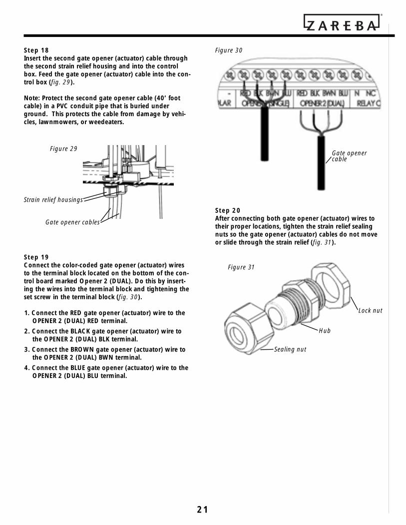
Step 18Insert the second gate opener (actuator) cable throughthe second strain relief housing and into the controlbox. Feed the gate opener (actuator) cable into the con-trol box (fig. 29).
Note: Protect the second gate opener cable (40’ footcable) in a PVC conduit pipe that is buried underground. This protects the cable from damage by vehi-cles, lawnmowers, or weedeaters.
Step 19Connect the color-coded gate opener (actuator) wiresto the terminal block located on the bottom of the con-trol board marked Opener 2 (DUAL). Do this by insert-ing the wires into the terminal block and tightening theset screw in the terminal block (fig. 30).
1. Connect the RED gate opener (actuator) wire to theOPENER 2 (DUAL) RED terminal.
2. Connect the BLACK gate opener (actuator) wire tothe OPENER 2 (DUAL) BLK terminal.
3. Connect the BROWN gate opener (actuator) wire tothe OPENER 2 (DUAL) BWN terminal.
4. Connect the BLUE gate opener (actuator) wire to theOPENER 2 (DUAL) BLU terminal.
Step 20 After connecting both gate opener (actuator) wires totheir proper locations, tighten the strain relief sealingnuts so the gate opener (actuator) cables do not moveor slide through the strain relief (fig. 31).
Sealing nut
Hub
Lock nut
Figure 31
Gate openercable
Figure 30
Strain relief housings
Gate opener cables
Figure 29

AUTOMATIC GATE OPENER • Installation Manual
22
Push-to-Open Installation
CAUTION! Ensure the gate does not open into publicareas and does not interfere with traffic or cause traffichazards.
In a push-to-open installation, the gate opener (actua-tor) is installed while the gate is in the closed positionand the gate opens out from the property.
NOTE: The optional push-to-open bracket is longerthan the pivot bracket included with this kit, and isrequired for this installation (part #GAB1). You willneed two push-to-open brackets for a dual gate installation.
Step 1 (fig. 32)Assemble the post mount bracket assembly by placingthe push-to-open bracket in between the two postmount brackets. Insert the 3/8” x 2” hex bolt throughthe center hole of the two post mount brackets and thepush-to-open bracket. Place a 3/8” washer, a 3/8” lockwasher, and a 3/8” hex nut on the bottom of the 3/8” x2” hex bolt and hand tighten.
Step 2 (fig. 33a and 33b)NOTE: Gate opener (actuator) should be in the retractedor closed position before attaching the gate bracket andthe post mount bracket assembly.
Attach the gate bracket and the post mount bracketassembly to the gate opener (actuator) by inserting aclevis pin through the holes in the gate bracket and thepost push-to-open bracket. Secure the clevis pins usingthe clevis pin clips.
Clevis pin clip
Post bracketassembly
3/8” x 1 1/4”clevis pin
Gate opener (actuator)
Clevis pin clip
Post bracketassembly
3/8” x 1 1/4”clevis pin
Gate opener (actuator)
Figure 33a
Figure 33b
Figure 32
3/8” lock washer
Post brackets
3/8” x 2” bolt
3/8” nut
3/8” washer
Push-To-Open Bracket
23
Gate in CLOSED position
Gate in OPEN position
Pinch areas
2” min.
2”min.
Figure 35
NOTE: Ensure the gate opener(actuator) and the push-to-openbracket do not bind in the gate-open and gate-closed positions.
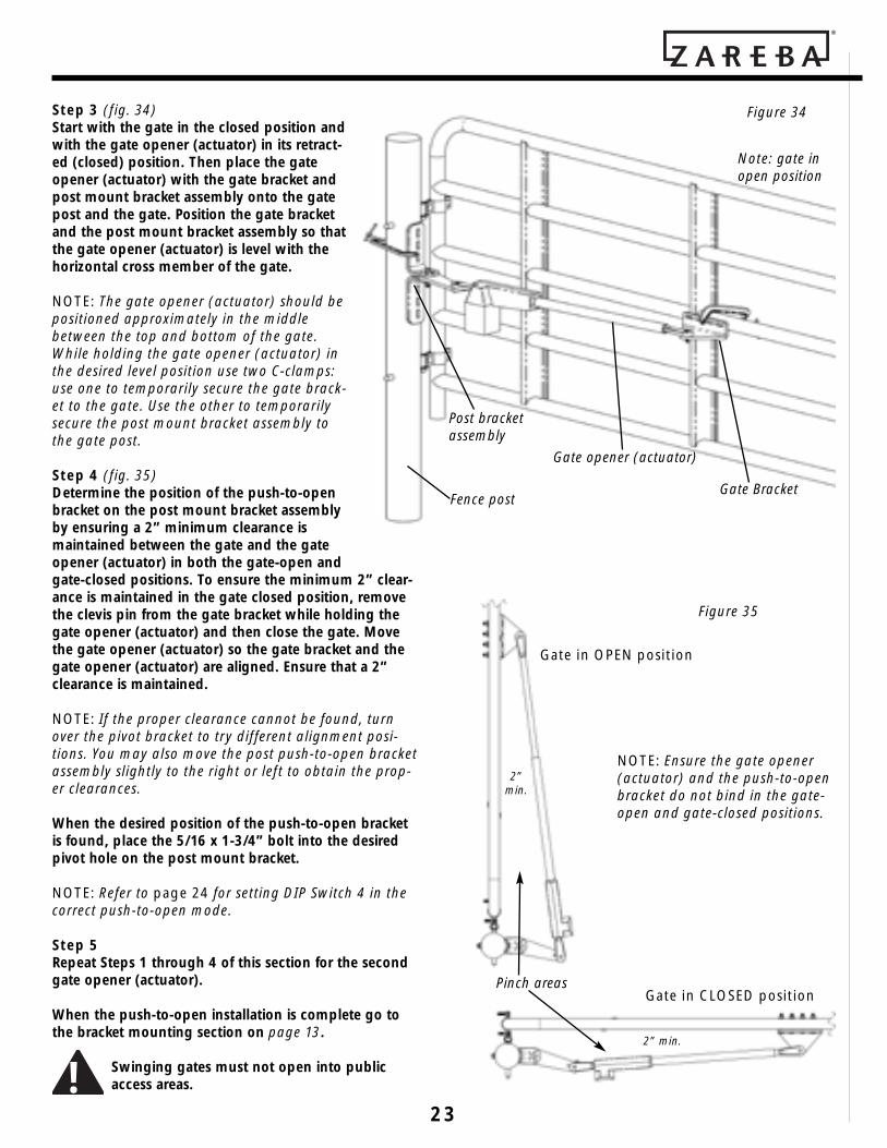
Step 3 (fig. 34)Start with the gate in the closed position andwith the gate opener (actuator) in its retract-ed (closed) position. Then place the gateopener (actuator) with the gate bracket andpost mount bracket assembly onto the gatepost and the gate. Position the gate bracketand the post mount bracket assembly so thatthe gate opener (actuator) is level with thehorizontal cross member of the gate.
NOTE: The gate opener (actuator) should bepositioned approximately in the middlebetween the top and bottom of the gate.While holding the gate opener (actuator) inthe desired level position use two C-clamps:use one to temporarily secure the gate brack-et to the gate. Use the other to temporarilysecure the post mount bracket assembly tothe gate post.
Step 4 (fig. 35)Determine the position of the push-to-openbracket on the post mount bracket assemblyby ensuring a 2” minimum clearance ismaintained between the gate and the gateopener (actuator) in both the gate-open andgate-closed positions. To ensure the minimum 2” clear-ance is maintained in the gate closed position, removethe clevis pin from the gate bracket while holding thegate opener (actuator) and then close the gate. Movethe gate opener (actuator) so the gate bracket and thegate opener (actuator) are aligned. Ensure that a 2”clearance is maintained.
NOTE: If the proper clearance cannot be found, turnover the pivot bracket to try different alignment posi-tions. You may also move the post push-to-open bracketassembly slightly to the right or left to obtain the prop-er clearances.
When the desired position of the push-to-open bracketis found, place the 5/16 x 1-3/4” bolt into the desiredpivot hole on the post mount bracket.
NOTE: Refer to page 24 for setting DIP Switch 4 in thecorrect push-to-open mode.
Step 5 Repeat Steps 1 through 4 of this section for the secondgate opener (actuator).
When the push-to-open installation is complete go tothe bracket mounting section on page 13.
Swinging gates must not open into publicaccess areas.
Gate opener (actuator)
Gate BracketFence post
Post bracketassembly
Figure 34
Note: gate inopen position
!

AUTOMATIC GATE OPENER • Installation Manual
24
Brick, Masonry, or Rock ColumnInstallation
Spacing requirements may prevent mounting the gateopener (actuator) on a column (see fig. 36). If this is thecase, the gate may have to be professionally re-hung ona post next to the column.
When mounting the gate opener (actuator) onto a col-umn, use of the push-to-open bracket (sold separately)may be necessary to ensure proper spacing betweenthe column and the opener.
If the proper spacing cannot be achieved using thepush-to-open bracket, the gate opener (actuator) mustbe installed using the push-to-open procedure (seepage 22).
If using the push-to-open procedure, ensure that thegate does not cause a traffic hazard.
CONTROL BOARD SETTINGS
You have several optional gate opener settings that arecontrolled via the DIP switches located inside the con-trol box.
DIP Switch Settings and Descriptions (fig. 37)
DIP Switch 1 – Soft Start/StopThe soft start and stop function slowly starts the gate asit begins to move, and slowly stops the gate as it beginsto stop. If used, this feature may prolong the life of yourgate opener system, due to less wear on the actuator(opener).
DIP Switch 2 – Warning BuzzerThe warning buzzer provides several different alarms.When the gate begins to move, the warning buzzer willsound an alarm for two seconds. It also sounds analarm when an obstruction occurs twice in any givencycle. The obstruction alarm cannot be disabled byturning this DIP switch to the OFF position.
DIP Switch 3 – Automatic CloseWhen this DIP switch is in the ON position, the gate willautomatically close after a period of time. The length oftime is determined by DIP switches 6 and 7. When thisDIP switch is OFF, the gate will stay open until a signal
is sent to close the gate. The signal can come from atransmitter, keypad, or push button control.
DIP Switch 4 – Push- or Pull-to-OpenThis switch is defaulted to the OFF position as that is thesetting for Pull-to-Open. Pull-to-Open is where the gateswings into the property. When the switch is in the ONposition, the system will work in Push-to-Open applica-tions or when the gate swings out from the property.
DIP Switch 5 – Momentary or Constant PressureThe default position is OFF. This switch should be left inthe OFF position unless a constant pressure push but-ton device is being used. This is typically done when agate attendant or guard is operating the gate. The gatethen can only be opened when constant pressure isapplied to a push button device.
DIP Switch 6 and 7 – Delay Time for AutomaticCloseSetting these two switches in a specific configurationwill determine the delay time before the gate will auto-matically close. DIP switch 3 must be in the ON positionfor these two switches to be in effect. See the accompa-nying table for settings.
DIP Switch 8 – Not Used
Figure 36
Gate
CONTROL BOX SETTING
Pivot bracket
Gate hinge
Point A
The distance from the pivot bracket to point “A” +the distance from the gate hinge to point “A”, CANNOT exceed 12”. For example: If the distancefrom the pivot bracket to point “A” is 5”, then thedistance from the gate hinge to point “A” cannotexceed 7”.

25
Dual DIP Switch Settings and Descriptions(fig. 38A)
DIP Switch 1 and 2 – Gate SequenceThe default position for both DIP switch 1 and 2 is OFF.The sequence of how the dual gates will close is deter-mined by how these two switches are configured.
DIP Switch 3 – Gate Closing DelayThe default setting is OFF. If DIP switch 3 is set to theON position, it will add four seconds of delay before thesecond gate closes. See examples below.
DIP Switch 4 – Closed Position LimitsThis switch is used when setting the closed position lim-its for each gate. The DIP switch is set to OFF when set-ting the closed position limit for the first gate. The DIPswitch is set to ON when setting the closed positionlimit for the second gate. See section “Setting the Gate’sClosed Limit Position” on page 27.
To Set Open/Close Sequence and Times:
1 ON; 2 OFF; 3 OFFFirst gate begins to opentwo seconds before secondgate. Second gate begins toclose four seconds beforefirst gate.
1 OFF; 2 OFFFactory setting for singleopener (actuator) operation.
Dual DIPswitches
Figure 38
DIP#6 DIP#7 Delay Time forAuto-close
ON ON 15 seconds
ON OFF 30 seconds
OFF ON 60 seconds
OFF* OFF* 120 seconds
DIP#1ON* – Soft start enabledOFF – Soft start disabled
DIP#2ON* – Gate moving audible warning enabledOFF – Gate moving audible warning disabled
(NOTE: obstruction alarm cannot be disabledby putting DIP switch in OFF position)
DIP#3ON – Auto-close enabledOFF* – Auto-close disabled (requires a signal to close)
DIP#4ON – Push-to-open operationOFF* – Pull-to-open operation
DIP#5ON – D1 mode, constant pressure to operate gateOFF* – B2 mode, momentary contact to operate gate
DIP#8Not used
*Default factory setting
Figure 37
(Note: DIP switch 6 and 7 settings are only in effectwhen DIP switch 3 in in ON position.)
NOTE: Your Zareba Autmatic Gate Opener receiver iscompatible with built-in vehicle transmitter systems,such as HomeLink. Refer to your vehicle owner’s manu-al for instruction on how to program.

AUTOMATIC GATE OPENER • Installation Manual
26
Setting the Transmitter CodeNOTE: All Zareba Automatic Gate Opener transmittersand receivers use a standard code set at the factory. Itis recommended that you set your own personal codefor safety and security.
Step 1 (fig. 39)Remove the battery access cover on the transmitter.When the cover is off, you will see the battery and theDIP switch.
Step 2 The DIP switch contains 10 small switches (fig. 40).Using a small screwdriver or pen, move any single orcombination of the switches to either the open orclosed position.
NOTE: Do not set the switches to all open or all closed.
Step 3Remove the RF receiver box cover by removing the fourscrews. When the cover is off, you will see the DIPswitches in the upper right corner.
Step 4There are 10 small DIP switches. Refer to the transmitterand using a small screw driver or pen, move the switch-es to the same positions as you did for the transmitter(fig. 40).
NOTE: The transmitter and RF receiver DIP switch set-ting must match exactly or the remote system will notwork.
Figure 40
Figure 39
DIP switch
To Set or Clear Position Limits:
4 ONTo set or clear second gateposition limit
4 OFFTo set or clear first gate position limit
1 OFF; 2 ON; 3 ONFirst and second gates openat the same time. Secondgate begins to close eightseconds before first gate.
1 OFF; 2 ON; 3 OFFFirst and second gates openat the same time. Secondgate begins to close fourseconds before first gate.
1 ON; 2 OFF; 3 ONFirst gate begins to opentwo seconds before secondgate. Second gate begins toclose eight seconds beforefirst gate.

27
Step 5Replace the battery access cover.
Step 6Check to see that the DIP switch settings match bypressing the transmitter button. If the gate moves, theDIP switch settings match.
If the gate does not move, adjust the transmitter DIPswitch settings to match the RF receiver DIP switch set-tings. Then press the transmitter button to verify thatthe gate moves.
Step 7Replace the RF receiver box cover.
Setting The Gate’s Closed Limit Position
Next you must set the gate opener’s CLOSED limit set-ting. (limit setting: the desired stopping point for yourgate) This will vary depending on if you are using apull-to-close (standard set up) or push-to-open (alterna-tive set up, see page 22) arrangement for your opener.
Pull-to-Close Closed Limit SettingStep 1Turn the power ON to energize the system.
Step 2Make sure both gates are in the fully open position.Press the transmitter button and the gates will begin toclose. Be prepared to stop the gates when the desiredlimit has been reached by the first gate opener (actuator) that closes first.
Step 3If Opener 2 was the first gate to close, set Dual ModeDIP switch 4 to the ON position. If Opener 1 was thefirst gate to close, set Dual Mode DIP switch 4 to theOFF position. Then press and hold the SET LIMIT buttonfor two seconds (fig. 41). The STATUS light will turn onmomentarilly, then turn off.
Figure 41
Step 4Press the button of the transmitter and the gates shouldmove to the fully open position. The first gate opener’s(actuator) closed position is now set for the opener thatclosed first.
Step 5Now press the transmitter button again. Your gatesshould begin to close. The opener that closes first willstop at the closed limit position you programmed in theprevious steps. The other gate will continue to closeuntil you press the transmitter button again. The sec-ond gate should close firmly up to the first gate withoutexcessive pressure against the first gate.
Step 6If Opener 2 was the second gate to close, set DualMode DIP switch 4 to the ON position. If Opener 1 wasthe second gate to close, set Dual Mode DIP switch 4 tothe OFF position. Then press and hold the SET LIMITbutton for two seconds. The STATUS light will turn onmomentarilly, then turn off.
Step 7Using the handheld transmitter return the gates to thefully open position. Both gates’ closed position stopsare now set.
Step 8Again, using the handheld transmitter close the gates toverify they meet the desired location. Note: If the gatesdid NOT reach the desired limit proceed to Step 9.
Step 9Clearing the closed limit setting for Opener 1:
a) Return the gate to the fully open position.b) Set Dual Mode DIP switch 4 to the OFF position.c) Press and hold the SET LIMIT button for five sec-
onds. When the green STATUS light comes on, theclosed limit setting has been reset to factorydefaults.
Clearing the closed limit setting for Opener 2:a) Return the gate to the fully open position.b) Set Dual Mode DIP switch 4 to the ON position.c) Press and hold the SET LIMIT button for five sec-
onds. When the green STATUS light comes on, theclosed limit setting has been reset to factorydefaults.

AUTOMATIC GATE OPENER • Installation Manual
28
Push-to-Open Open Limit Setting
Step 1Turn the power ON to energize the system.
Step 2Make sure both gates are in the fully closed position.Press the transmitter button and the gates will begin toopen. Be prepared to stop the gates when the desiredlimit has been reached by the first gate opener (actuator) that opens first.
Step 3If Opener 2 was the first gate to open, set Dual ModeDIP switch 4 to the ON position. If Opener 1 was thefirst gate to open, set Dual Mode DIP switch 4 to theOFF position. Then press and hold the SET LIMIT buttonfor two seconds (fig. 42). The STATUS light will turn onmomentarilly, then turn off.
Step 4Press the button of the transmitter and the gates shouldmove to the fully closed position. The open position isnow set for the opener that opened first.
Step 5Now press the transmitter button again. Your gatesshould begin to open. The opener that opens first willstop at the open limit position you programmed in theprevious steps. The other gate will continue to openuntil you press the transmitter button again.
Step 6If Opener 2 was the second gate to open, set DualMode DIP switch 4 to the ON position. If Opener 1 wasthe second gate to open, set Dual Mode DIP switch 4 tothe OFF position. Then press and hold the SET LIMITbutton for two seconds. The STATUS light will turn onmomentarilly, then turn off.
Step 7Using the handheld transmitter return the gates to thefully closed position. Both gates’ opened position stopsare now set.
Figure 42
Step 8Again, using the handheld transmitter open the gates toverify they meet the desired location. Note: If the gatesdid NOT reach the desired limit proceed to Step 9.
Step 9Clearing the open limit setting for Opener 1:
a) Return the gate to the fully closed position.b) Set Dual Mode DIP switch 4 to the OFF position.c) Press and hold the SET LIMIT button for five sec-
onds. When the green STATUS light comes on, theopen limit setting has been reset to factorydefaults.
Clearing the open limit setting for Opener 2:a) Return the gate to the fully closed position.b) Set Dual Mode DIP switch 4 to the ON position.c) Press and hold the SET LIMIT button for five sec-
onds. When the green STATUS light comes on, theopen limit setting has been reset to factorydefaults.
Automatic Close Time Adjustment
Step 1There are five different automatic close time adjust-ments available (refer to fig. 37, on page 25, for details).To turn the automatic close time adjustment off, placeauto-close DIP switch in OFF position.
Step 2To set the timer to close automatically after the gate hasbeen opened, set the DIP switches according to thetable on page 25.
Obstruction Sensitivity Set Up
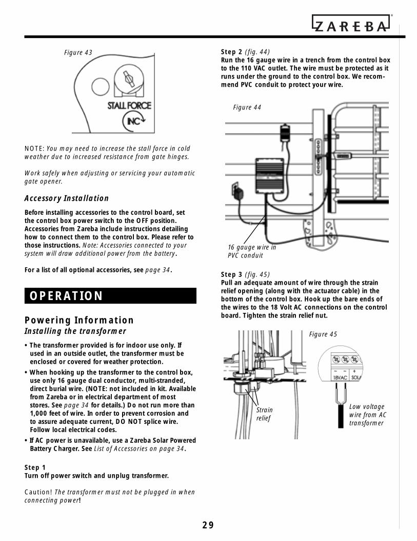
IMPORTANT: For safety reasons the obstruction settingor stall force on the Zareba Automatic Gate Openercontrol board comes from the factory set at minimum,turned all the way counter-clockwise. In many gateinstallations, this setting will need to be adjusted toovercome the weight and size of the gates.
The stall force potentiometer on the circuit board con-trols the obstruction sensitivity (or the amount of forcethe opener will apply to an obstruction) before it auto-matically stops and reverses direction of the gate afterapproximately two seconds. Adjust the sensitivitybeginning at the factory default counter-clockwise posi-tion (fig. 43). Continue to incrementally increase theforce until the gate can open and close withoutobstructing under its own weight.
29
NOTE: You may need to increase the stall force in coldweather due to increased resistance from gate hinges.
Work safely when adjusting or servicing your automaticgate opener.
Accessory Installation
Before installing accessories to the control board, setthe control box power switch to the OFF position.Accessories from Zareba include instructions detailinghow to connect them to the control box. Please refer tothose instructions. Note: Accessories connected to yoursystem will draw additional power from the battery.
For a list of all optional accessories, see page 34.
Powering InformationInstalling the transformer
• The transformer provided is for indoor use only. Ifused in an outside outlet, the transformer must beenclosed or covered for weather protection.
• When hooking up the transformer to the control box,use only 16 gauge dual conductor, multi-stranded,direct burial wire. (NOTE: not included in kit. Availablefrom Zareba or in electrical department of moststores. See page 34 for details.) Do not run more than1,000 feet of wire. In order to prevent corrosion andto assure adequate current, DO NOT splice wire.Follow local electrical codes.
• If AC power is unavailable, use a Zareba Solar PoweredBattery Charger. See List of Accessories on page 34.
Step 1Turn off power switch and unplug transformer.
Caution! The transformer must not be plugged in whenconnecting power!
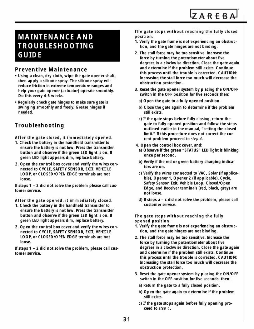
Figure 43 Step 2 (fig. 44)Run the 16 gauge wire in a trench from the control boxto the 110 VAC outlet. The wire must be protected as itruns under the ground to the control box. We recom-mend PVC conduit to protect your wire.
Step 3 (fig. 45)Pull an adequate amount of wire through the strainrelief opening (along with the actuator cable) in thebottom of the control box. Hook up the bare ends ofthe wires to the 18 Volt AC connections on the controlboard. Tighten the strain relief nut.
Low voltagewire from ACtransformer
Strain relief
Figure 45
16 gauge wire inPVC conduit
Figure 44
OPERATION

AUTOMATIC GATE OPENER • Installation Manual
30
Step 4 (fig. 46)Attach the other ends of the wire to the transformer terminals.
Step 5 (fig. 47)Plug the transformer into the electrical outlet. An ACsurge protector (not included) is recommended.
Manual operation of gate
CAUTION: The gate will move freely and uncontrolledwhen the gate opener (actuator) is removed from thegate. ONLY disconnect the gate opener (actuator) whenthe control box power switch is OFF and the gate isNOT moving.
Disconnecting the Opener (fig. 48)1. Turn control box power switch OFF.2. Remove clevis pin clip and clevis pin from either the
front or rear mounting point.3. Remove the gate opener (actuator) from the mount.
The gate can be opened and closed manuallywhen the gate opener (actuator) is disconnected.
Figure 47
Transformer
Figure 46
Theft Deterrence
Your Zareba Automatic Gate Opener comes with a built-in theft deterrence feature. If the gate opener (actuator)is disconnected from the control box, your unit willautomatically sound an alarm, notifying you of unau-thorized removal of the actuator. A warning label on thegate opener (actuator) states an alarm will sound if theactuator is removed. The alarm is shut off by discon-necting battery power to the control box or turning theswitch on the bottom of the control box to the OFFposition.
For additional protection, a pin lock accessory can bepurchased to lock your gate opener (actuator) to abracket preventing removal of the gate opener (actua-tor)(see fig. 49).
NOTE: Substitute a Pin Lock for the clevis pin on thefront mount of the gate opener (actuator) (fig. 45) toprevent unauthorized removal of the gate opener (actuator) from the gate (see List of Accessories onpage 34).
Figure 49
Pin Lock (GPL1) soldas an accessory
Clevis pin clip
Clevis pin
Gate opener(actuator)
Gate bracket mount
Figure 48
!
31
The gate stops without reaching the fully closedposition.1. Verify the gate frame is not experiencing an obstruc-
tion, and the gate hinges are not binding.2. The stall force may be too sensitive. Increase the
force by turning the potentiometer about fivedegrees in a clockwise direction. Close the gate againand determine if the problem still exists. Continuethis process until the trouble is corrected. CAUTION:Increasing the stall force too much will decrease theobstruction protection.
3. Reset the gate opener system by placing the ON/OFFswitch in the OFF position for five seconds then:
a) Open the gate to a fully opened position.b) Close the gate again to determine if the problem
still exists.c) If the gate stops before fully closing, return the
gate to fully opened position and follow the stepsoutlined earlier in the manual, “setting the closedlimit.” If this procedure does not correct the cur-rent problem proceed to step 4.
4. Open the control box cover, and:a) Observe if the green “STATUS” LED light is blinking
once per second.b) Verify if the red or green battery charging indica-
tors are on.c) Verify the wires connected to VAC, Solar (if applica-
ble), Opener 1, Opener 2 (if applicable), Cycle,Safety Sensor, Exit, Vehicle Loop, Closed/OpenEdge, and Receiver terminals (red, black, grey) arenot loose.
d) If steps a – c did not solve the problem, please callcustomer service.
The gate stops without reaching the fullyopened position.1. Verify the gate frame is not experiencing an obstruc-
tion, and the gate hinges are not binding.2. The stall force may be too sensitive. Increase the
force by turning the potentiometer about fivedegrees in a clockwise direction. Close the gate againand determine if the problem still exists. Continuethis process until the trouble is corrected. CAUTION:Increasing the stall force too much will decrease theobstruction protection.
3. Reset the gate opener system by placing the ON/OFFswitch in the OFF position for five seconds, then:
a) Return the gate to a fully closed position.b) Open the gate again to determine if the problem
still exists.c) If the gate stops again before fully opening pro-
ceed to step 4.
Preventive Maintenance • Using a clean, dry cloth, wipe the gate opener shaft,
then apply a silicone spray. The silicone spray willreduce friction in extreme temperature ranges andhelp your gate opener (actuator) operate smoothly.Do this every 4-6 weeks.
• Regularly check gate hinges to make sure gate isswinging smoothly and freely. Grease hinges if needed.
Troubleshooting
After the gate closed, it immediately opened.1. Check the battery in the handheld transmitter to
ensure the battery is not low. Press the transmitterbutton and observe if the green LED light is on. Ifgreen LED light appears dim, replace battery.
2. Open the control box cover and verify the wires con-nected to CYCLE, SAFETY SENSOR, EXIT, VEHICLELOOP, or CLOSED/OPEN EDGE terminals are notloose.
If steps 1 – 2 did not solve the problem please call cus-tomer service.
After the gate opened, it immediately closed.1. Check the battery in the handheld transmitter to
ensure the battery is not low. Press the transmitterbutton and observe if the green LED light is on. Ifgreen LED light appears dim, replace battery.
2. Open the control box cover and verify the wires con-nected to CYCLE, SAFETY SENSOR, EXIT, VEHICLELOOP, or CLOSED/OPEN EDGE terminals are notloose.
If steps 1 – 2 did not solve the problem, please call cus-tomer service.
MAINTENANCE ANDTROUBLESHOOTINGGUIDE

AUTOMATIC GATE OPENER • Installation Manual
32
4. Follow the instructions for setting the CLOSED limit.If the gate continues to stop without reaching thefully opened position proceed to step 5.
5. Open the control box cover, and:a) Observe if the green “STATUS” LED light is blinking
once per second.b) Verify if the red or green battery charging indica-
tors are on.c) Verify the wires connected to VAC, Solar (if applica-
ble), Opener 1, Opener 2 (if applicable), Cycle,Safety Sensor, Exit, Vehicle Loop, Closed/OpenEdge, and Receiver terminals (red, black, grey) arenot loose.
d) If steps a – c did not solve the problem, please callcustomer service.
The gate will not open using the handheldtransmitter.1. Remove the cover from the transmitter.2. Remove the RF receiver box cover. Verify the DIP
switch settings on the transmitter are the same asthose in the receiver.
3. If steps 1– 2 do not reveal an existing problem,please contact customer service for further assis-tance.
The gate will not open or close.1. If applicable, ensure the 18 VAC transformer is still
plugged into the 110 VAC source.2. Open the control box cover, and:
a) Observe if the green “STATUS” LED light is blinkingonce per second.
b) Verify if the red or green battery charging indica-tors are on.
c) Verify the wires connected to VAC, Solar (if applica-ble), Opener 1, Opener 2 (if applicable), Cycle,Safety Sensor, Exit, Vehicle Loop, Closed/OpenEdge, and Receiver terminals (red, black, grey) arenot loose.
3. Verify the 15 amp fuse is not blown.If steps 1– 3 do not reveal an existing problem, pleasecontact customer service.
When my gates close, they do not align witheach other.1. Clear your closed limit settings. Return the gates to
the fully open position. Press and hold the SET LIMITbutton for five seconds until the green LED turns off.The closed limit setting is now erased.
2. Repeat steps 1 – 8 from the section of the manualtitled “Setting the Gate’s Closed Limit Position”
3. Verify gates close and are aligned properly.If steps 1 – 3 do not resolve the problem, please con-tact customer service.
Customer Service8:00am to 5:00pm, Central time, Monday – FridayZareba Systems906 Fifth Avenue EEllendale, MN 56026-2193Phone: 800-272-9877 or 507-684-3721 Fax: 507-684-3722; Email: [email protected]

33
Warranty and RepairInformation
If your Zareba Automatic Gate Opener is not operatingproperly, please follow all troubleshooting proceduresin the Maintenance and Troubleshooting Guide (page31). If you are unable to solve the problem, call ZarebaSystems at 1-800-272-9877, or visit the Automatic GateOpener section of our web site at www.zarebasystems.com. We will help with trou-bleshooting and arrange repair or replacement, if need-ed. When you call, please have the model and serialnumber of the Zareba Automatic Gate Opener.
One Year Limited Warranty
Limited Warranty CoverageIf your Automatic Gate Opener (sometimes also referred to as the“Product”) does not work properly because of a defect in materi-als or workmanship, the Zareba Systems division of Waters,Instruments, Inc. (“Zareba”) will, for the length of the period indi-cated on the chart below, which starts with the date of originalpurchase (the “Limited Warranty period”), at its option either (a)repair your Product with new or refurbished parts, or (b) replaceit with a new or a refurbished Product. The decision to repair orreplace will be made by Zareba.
Parts LaborOne (1) Year One (1) Year
During the “Labor” Limited Warranty period there will be nocharge for labor. (Note: labor applies only to the repair of theProduct at an Authorized Zareba Repair Center. It does not applyto removal or installation of the Product on purchaser’s home orother premises). During the “Parts” Limited Warranty period,there will be no charge for parts.
You must ship your Zareba Automatic Gate Opener to Zareba dur-ing the applicable Limited Warranty period. This Limited Warrantyexcludes both parts and labor for batteries, antennas, and cos-metic parts (such as the Product housing). This Limited Warrantyonly applies to Products purchased in the United States. ThisLimited Warranty is extended only to the original consumer pur-chaser (“you” or “your”) of a new Product that was not sold “as is”.
Limited Warranty ServiceFor assistance in the continental U.S.A. in obtaining the benefit ofthe Limited Warranty please carefully follow these steps:
1) Complete carefully all troubleshooting procedures in theMaintenance and Troubleshooting Guide in this Manual.
2) If you are still unable to solve the problem, contact ZarebaSystems customer service at 1-800-272-9877. Please havethe model and serial number of the Product available togive to the customer service representative. The customerservice representative will provide further assistance orauthorize repair or replacement, as appropriate.
3) If repair or replacement is appropriate you will be given areturn authorization number (RMA#). This RMA# must bevisible on all documents and packages returned to Zareba.
4) Carefully pack the defective Product or Product part in asturdy shipping carton, include (i) a letter detailing thecomplaint, (ii) a daytime phone number where you can bereached, (iii) your name and address for any return, (iv)your sales receipt/proof of purchase, and (v) the RMA# onall correspondence and the shipping carton.
5) Prepay the freight and insure the defective Product orProduct part against shipping damage. Note that defectiveProducts or Product parts shipped freight collect will not beaccepted.
6) Ship the carton to: Zareba Systems, 906 Fifth Avenue E.,Ellendale, MN 56026, or where directed by the customerservice representative.
IF REPAIR OR REPLACEMENT IS NEEDED DURING THE LIMITEDWARRANTY PERIOD, THE PURCHASER WILL BE REQUIRED TOFURNISH A SALES RECEIPT/PROOF OF PURCHASE INDICATINGDATE OF PURCHASE, AMOUNT PAID AND PLACE OF PUR-CHASE. THE PURCHASER WILL BE CHARGED FOR THE REPAIROF ANY PRODUCT OR PRODUCT PART RECEIVED WITHOUTSUCH PROOF OF PURCHASE OR FOR REPAIRS REQUESTEDOUTSIDE OF THE APPLICABLE LIMITED WARRANTY PERIOD.
Limited Warranty Limitations and ExclusionsThis Limited Warranty ONLY COVERS failures due to defects inmaterials or workmanship, and DOES NOT COVER normal wearand tear or cosmetic damage. The Limited Warranty ALSO DOESNOT COVER damages which occurred in shipment, or failureswhich are caused by products not supplied by Zareba, or failureswhich result from accidents, misuse, abuse, neglect, mishandling,misapplication, modifications or alterations, faulty installation,connection to an improper power source, set-up adjustments,misadjustment of controls, improper maintenance, power linesurges, damage from acts of God such as lightning, wind, fire,flood or insects, introduction of sand, humidity or liquids, com-mercial or rental use or service by anyone other than anAuthorized Zareba Repair Center.
THERE ARE NO EXPRESS WARRANTIES EXCEPT AS STATEDUNDER “LIMITED WARRANTY COVERAGE”. ZAREBA IS ANDWILL NOT BE LIABLE FOR INCIDENTAL OR CONSEQUENTIALDAMAGES RESULTING FROM THE USE OF THE PRODUCT, ORARISING OUT OF ANY BREACH OF THIS LIMITED WARRANTY.(As examples, this excludes damages for lost time, lost calls ormessages, cost of having someone remove or re-install aninstalled Product or Product part, travel to and from anAuthorized Zareba Repair Center, etc. The examples listed are notan exhaustive or exclusive list, but are for illustration only). ALLEXPRESS AND IMPLIED WARRANTIES, INCLUDING ANYIMPLIED WARRANTIES OF MERCHANTABILITY OR FITNESS FORA PARTICULAR PURPOSE, ARE LIMITED TO THE PERIOD OF THELIMITED WARRANTY.
Some States do not allow the exclusion or limitation of incidentalor consequential damages, so the above limitation or exclusionmay not apply to you.
Some States do not allow limitations on how long an impliedwarranty lasts, so the above limitation may not apply to you.
This warranty gives you specific legal rights, and you may alsohave other rights which vary from State to State.
PARTS AND SERVICES WHICH ARE NOT EXPRESSLY COVERED BYTHIS LIMITED WARRANTY ARE YOUR RESPONSIBILITY.

AUTOMATIC GATE OPENER • Installation Manual
34
Solar Powered Battery Charger (GSP1). The Solar Panel charges the 12 volt battery when ACpower is not available, or is more than 1,000 feet away. Cycles are limited by the number of panelsinstalled and the geographic location of gate opener installation.
Push-Button Control (GB1). Opens the gate with a push of a button. The Push Button Control issimilar to a doorbell or the button-type control commonly used to open garage doors. The PushButton Control can be located in a garage or other location that is easily accessible when wantingto open or close the gate. It connects directly to the control box.
Pin Lock (GPL1). The Pin Lock replaces the clevis pin when mounting the actuator to the brackets.It helps to prevent theft of the actuator from the gate, while allowing quick release of the opener.
One-Button Transmitter (GT1). The Transmitter works similar to transmitters frequently used withgarage door openers. It allows you to open or close the gate from a remote location (typicallyyour vehicle). It has a range up to 300 feet.
Two Button Transmitter (GT2). The Two Button Transmitter provides the capability to remotelyoperate two separate devices such as two gates, or a gate and garage door. It has a range up to300 feet.
Three Button Transmitter (GT3). The Three Button Transmitter provides the ability to remotelyoperate three separate devices. It has a range up to 300 feet.
Mini Transmitter (GKF1). The Key Chain Transmitter fits on a keychain and allows you to openand close the gate from a remote location. It has a range up to 300 feet.
Keypad (GKP1). The Keypad allows for entry by authorized guests informed of your pre-set code.Entering the correct code causes the gate to open or close. The access code is easily modified.
In-Ground Vehicle Sensor (GS1). The In-Ground Vehicle Sensor provides a method to open yourgate without a transmitter, push button, or keypad. Typically, the Sensor is installed on the insideof the property allowing guests to leave without having a control device to open the gate. Thesensor is buried near the gate and senses or detects a metal vehicle that passes within its 12-footrange. Once detected, the gate opens automatically.
Push-to-Open Bracket (GAB1). This bracket is necessary for push-to-open installations. Push-to-open installations may become necessary due to a sloped driveway or other installation-specificreasons.
Replacement Battery (GRB1). Standard 12 volt, 7.2 amp-hour, maintenance-free battery for theZareba Automatic Gate Opener.
Low-Voltage Wire (GW1). 16-gauge, multi-stranded, dual-conductor low voltage wire used toconnect the AC-powered transformer to the control box.
Automatic Gate Lock (GL1). The Automatic Gate Lock provides an additional level of security foryour property. When your gate swings shut, the gate lock closes, securing your gate in the closedposition.
Please check with your local Zareba retailer for products. If the products you need are not avail-able, you may purchase them directly from Zareba Systems.
GATE OPENER ACCESSORIES
AUTOMATIC
GATE
OPENER BATTERY

35
GATE OPENER ACCESSORY ORDER FORM
Prices and shipping subject to change without notice.
*Shipping & Handling (ground): Under $50: $8.00Note: For air freight shipping, $50 to $100: $11.00contact the factory for cost $100 to $200: $14.00
$200 to $300: $17.00Over $300: Contact factory
**Residents in CA, MN, NJ, and NY, add appropriate state tax.
Mail order form and payment to: Zareba Systems906 Fifth Avenue EEllendale, MN 56026-2193
Pay via credit card by calling 800-272-9877, or fax order to 507-684-3722. ! Master Card ! Visa ! Discover
Card Number:________________________ Expiration Date:____________ Signature:____________________________
Send product to: (please print)
Name:________________________________________________________________________________________________
Address: ______________________________________________________________________________________________
City, State, Zip: ________________________________________________________________________________________
Phone: ( ) __________________ Email:_______________________________________________________________
Accessory Model No. Price Qty Extended Price
Single Gate Opener Kit G750 $595.00
Double Gate Opener Kit G752 $875.00
Solar Powered Battery Charger GSP1 $145.00
Push Button Control GB1 $11.00
Pin Lock GPL1 $29.50
Push-To-Open Adapter Bracket GAB1 $26.50
One-Button Transmitter GT1 $28.00
Two-Button Transmitter GT2 $47.00
Three-Button Transmitter GT3 $52.00
Mini-Transmittor GKF1 $28.00
Digital Keypad GKP1 $70.00
Replacement Battery GRB1 $42.00
Low Voltage Wire (sold in 1-foot increments call for pricing) GW1
In-Ground Vehicle Sensor GS1 $210.00
AC Surge Suppressor 1549.96 $8.74
Sub Total
*Shipping and Handling
**Tax
Total