A time-implicit filling algorithm - ung.sisabotin.ung.si/~sarler/VOLLER/enthfill.pdfA time-implicit...
8
A time-implicit filling algorithm C. R. Swaminathan Department of Mechanical Engineering, University of Minnesota, Minneapolis, MN, USA V. R. Voller Department of Civil and Mineral Engineering, University of Minnesota, Minneapolis, MN, USA The volume ofpuid (VOF) equation is a w&known method for tracking the liquid/air interface during a filling process. Standard numerical approximations of the VOF equation fail to preserve a sharp interface. Methods that ensure a sharp interface in VOF calculations are investigated in this paper. At first, two previous VOF schemes that limit the smearing of the interface, via appropriate approximation of the convectivepux, are outlined. These schemes are explicit in nature and hence subject to time step restrictions. A new scheme for approximating the convective flux is introduced. Implicit solutions based on this modified scheme are smear free and are not subject to any time step restrictions. Solutions to exampleJilling problems are in close agreement with solutions based on traditional VOF approaches, Some potential drawbacks of the new method are investigated. In the context ofjlling problems it is shown that these drawbacks are not significant. Keywords: mold filling, front tracking Introduction In recent times, due to energy and product quality requirements, numerical modelling of casting processes has become an important area of study.rP6 A critical aspect in this work, in addition to the modelling of solidification, microstructure, and stress evolution, is the development and investigation of free surface algorithms to model the filling pattern.7P’5 The filling stage in a casting process involves the introduction of liquid metal into the mold cavity. The objective of a filling model is to predict the filling of the mold on tracking the liquid/air free surface. The manner in which the mold fills has a direct influence on the subsequent heat transfer in the casting and also plays a key role in determining the location of defects such as porosity. An ideal filling algorithm should be Compatible with and easily implemented in general- purpose heat and mass transfer codes. During casting, filling is usually not an isolated process but is accom- panied by heat and mass transfer processes. The complex coupling between filling and other processes can be readily handled in a general-purpose heat and mass transfer code. Efficient. From a numerical standpoint, the filling algorithm should not impose any restrictions on the overall simulation of the casting process, i.e., one Address reprint requests to Dr. Voller at the University of Minnesota, Dept. of Civil and Mineral Engineering, Minneapolis, MN 55455, USA. Received 29 September 1992; revised 8 July 1993; accepted 28 July 1993 would prefer the filling algorithm to be free of the Courant condition,i6 which imposes restrictions on the time step used in a given simulation. 3. Independent of numerical method. The method should be applicable in both finite difference and finite element based approaches. The majority of filling algorithms to date have been implemented within a finite difference framework.7P13 Examples of algorithms based on finite elements although avail- able 14,r5 are “thinner on the ground.” In terms of modelling shape-castings a finite-element-based algo- rithm would have the distinct advantage of being able to fit the required geometry. The objective of this paper is to introduce a new filling algorithm that has the above attributes. Overview of existing filling approaches In order to set the stage, a brief overview of existing filling algorithms is presented. Consider as an example, the filling of an initially empty two-dimensional cavity as shown in Figure 1 (a). In a broad sense, three different classes of methods can be identified: 1. Lagrangian. In this approach, the computational space grid deforms as the calculation proceeds such that a line of node points (or grid element boundaries) always coincides with the free surface,17 see Figure 1 (b). This approach requires a large computational time. Also, regridding may be essential when the grid gets too contorted. 0 1994 Butterworth-Heinemann Appl. Math. Modelling, 1994, Vol. 18, February 101
Transcript of A time-implicit filling algorithm - ung.sisabotin.ung.si/~sarler/VOLLER/enthfill.pdfA time-implicit...

A time-implicit filling algorithm
C. R. Swaminathan
Department of Mechanical Engineering, University of Minnesota, Minneapolis, MN, USA
V. R. Voller
Department of Civil and Mineral Engineering, University of Minnesota, Minneapolis, MN, USA
The volume ofpuid (VOF) equation is a w&known method for tracking the liquid/air interface during a filling process. Standard numerical approximations of the VOF equation fail to preserve a sharp interface. Methods that ensure a sharp interface in VOF calculations are investigated in this paper. At first, two previous VOF schemes that limit the smearing of the interface, via appropriate approximation of the convectivepux, are outlined. These schemes are explicit in nature and hence subject to time step restrictions. A new scheme for approximating the convective flux is introduced. Implicit solutions based on this modified scheme are smear free and are not subject to any time step restrictions. Solutions to exampleJilling problems are in close agreement with solutions based on traditional VOF approaches, Some potential drawbacks of the new method are investigated. In the context ofjlling problems it is shown that these drawbacks are not significant.
Keywords: mold filling, front tracking
Introduction
In recent times, due to energy and product quality requirements, numerical modelling of casting processes has become an important area of study.rP6 A critical aspect in this work, in addition to the modelling of solidification, microstructure, and stress evolution, is the development and investigation of free surface algorithms to model the filling pattern.7P’5 The filling stage in a casting process involves the introduction of liquid metal into the mold cavity. The objective of a filling model is to predict the filling of the mold on tracking the liquid/air free surface. The manner in which the mold fills has a direct influence on the subsequent heat transfer in the casting and also plays a key role in determining the location of defects such as porosity. An ideal filling algorithm should be
Compatible with and easily implemented in general- purpose heat and mass transfer codes. During casting, filling is usually not an isolated process but is accom- panied by heat and mass transfer processes. The complex coupling between filling and other processes can be readily handled in a general-purpose heat and mass transfer code. Efficient. From a numerical standpoint, the filling algorithm should not impose any restrictions on the overall simulation of the casting process, i.e., one
Address reprint requests to Dr. Voller at the University of Minnesota, Dept. of Civil and Mineral Engineering, Minneapolis, MN 55455, USA.
Received 29 September 1992; revised 8 July 1993; accepted 28 July 1993
would prefer the filling algorithm to be free of the Courant condition,i6 which imposes restrictions on the time step used in a given simulation.
3. Independent of numerical method. The method should be applicable in both finite difference and finite element based approaches. The majority of filling algorithms to date have been implemented within a finite difference framework.7P13 Examples of algorithms based on finite elements although avail- able 14,r5 are “thinner on the ground.” In terms of modelling shape-castings a finite-element-based algo- rithm would have the distinct advantage of being able to fit the required geometry.
The objective of this paper is to introduce a new filling algorithm that has the above attributes.
Overview of existing filling approaches
In order to set the stage, a brief overview of existing filling algorithms is presented. Consider as an example, the filling of an initially empty two-dimensional cavity as shown in Figure 1 (a). In a broad sense, three different classes of methods can be identified:
1. Lagrangian. In this approach, the computational space grid deforms as the calculation proceeds such that a line of node points (or grid element boundaries) always coincides with the free surface,17 see Figure 1 (b). This approach requires a large computational time. Also, regridding may be essential when the grid gets too contorted.
0 1994 Butterworth-Heinemann Appl. Math. Modelling, 1994, Vol. 18, February 101

A time-implicit filling algorithm: C. R. Swaminathan and V. R. Voller
=E 4
(a) (b)
(cl (4
Figure 1. Filling of a two-dimensional cavity: (a) problem specification, (b) Lagrangian approach, (c) marker and cell (MAC) approach, and (d) volume of fluid (VOF) approach.
Marker and cell (MAC) method. This method follows the progress of the free surface through a fixed Eulerian space grid by tracking the movement of imaginary tracer particles, see Figure I(c). One of the earliest filling algorithms was based on this technique. 8,9 This requires an explicit time stepping scheme so that the motion of the marker particles is restricted to a maximum of one cell. Volume of fluid (VOF) method. A widely used ap- proach for modelling filling problems is the volume of fluid (VOF) technique developed by Hirt and Nichols.18 In this approach, the free surface is tracked on solving a transport equation of the form
& (p,F) + v. (p,iiF) = 0 (1)
where pr is the density of the liquid, li is the velocity, and F is the volume fraction of the liquid. In a solution based on a fixed grid of computational cells, a value of F equal to zero would indicate an empty cell, F equals one would indicate a full cell and a fractional value of F would indicate a partially filled cell (see Figure I(d)). Lin and Hwang” and Stoehr and Wang” among others have developed and used the finite difference based SOLA-VOF technique’s to solve a variety of filling problems. More recently Dhatt et a1.14 and Usmani et a1.15 have implemented the VOF equation within a finite element framework to model the filling of complex shape castings.
A further look at the VOF method
The work in this paper will focus on issues related to the VOF method. On a naive level, this approach appears to be relatively straightforward, simply requiring the solution of an additional transport equation along with
the standard Navier-Stokes equations. However, be- cause the VOF equation is governed by convection alone, its discrete representation is prone to the usual numerical problems associated with the handling of convection terms.” This can best be illustrated by con- sidering a simple one-dimensional test problem as shown in Figure 2. A tube of unit length is being filled with an inviscid fluid. Initially the tube is assumed to be empty. The fluid comes in at a constant unit velocity. The density of the liquid is assumed to be constant.
A general control volume discrete approximation to equation (1) for this one-dimensional problem can be written as
F; - F; pAx+u,F,-uu,F,=O
At
where the superscript [ 1” and [I” represent the new and old time step value, the subscript [ lP represents the node point P while the subscripts [ 1, and [ 1, represent the control volume interfaces (see Figure 2). The standard means for approximating the interface quantities, F, and F,, is to use an upwind-difference formulation.” Two possible discrete representations are
Explicit: FF - F; + Cr(F$ - F”,) = 0 (3)
or
Implicit: FF - Fop + Cr(F”, - F”,) = 0 (4)
In equations (3) and (4), Cr is the discrete Courant number (u At/Ax). For the explicit scheme the value of Cr must be below 1.
In the computational runs a uniform grid of 10 cells is used to discretize the domain. The result of the computation in terms of F values at all the nodes at a time of 0.48 s is shown in Table I (see columns 3 and 4). The smear in the solution is due to a false dzjfiision effect, which we shall refer to as artljiciai dispersion. Essentially in both the schemes, as soon as the F value in a computational cell becomes greater than zero, the fluid can numerically “leak out” of that cell and enter cells ahead of it. Because of the nature of the explicit scheme, this leak is restricted to just one cell ahead per time step. In the implicit scheme, however, the fluid is effectively dispersed to all the cells in the domain during the first time step itself. Note that this artificial dispersion pheno- menon is different from crosswind d@usion,” usually associated with steady-state two-dimensional convec- tion-dominated transport problems. In multidimensional problems, it is possible that both artificial dispersion and crosswind diffusion occur simultaneously.
!--- Ax 4
Figure 2. A simple one-dimensional filling problem: problem specification and discretization details.
102 Appl. Math. Modelling, 1994, Vol. 18, February
A time-implicit filling algorithm: C. R. Swaminathan and V. R. Voller
Table 1. Performance comparison of a variety of schemes on the simple one-dimensional filling problem (Value of F at all the nodes at 0.48 s)
Node Exact Explicit Cr = 0.6
Implicit Cr= 1.2
Donor- acceptor Cr = 0.6
van Leer Cr = 0.6
Proposed Cr= 1.2
1 1 2 1 3 1 4 1 5 0.8 6 0 7 0 8 0 9 0
10 0
0.999345 0.991480 0.950193 0.826330 0.594086 0.315395 0.106376 0.016796
0 0
0.957312 0.864173 0.737167 0.598614 0.466359 0.350937 0.256500 0.182913 0.127723 0.087585
1 0.999998 1 1 0.999898 1 1 0.997167 1 1 0.952579 1
0.8 0.637971 0.8 0 0.193431 0 0 0.018194 0 0 0.000762 0 0 0 0 0 0 0
Within a control volume framework, two methods that can overcome the effects of artificial dispersion are:
The donor-acceptor flux approximation.*’ In this approach, the information both upstream and down- stream of the flux boundary is used to estimate the interface shape, which is then used in computing the convective flux. Table I (column 5) shows that the use of the donor-acceptor approximation on the simple one-dimensional problem eliminates the smear. Examples of the use of this approach used to model mold filling can be found in Refs. 10 and 11. The van Leer flux approximation.*’ In this technique, a second-order upstream-centered scheme is used to approximate the convective flux. Further, monotoni- city is ensured to prevent numerical oscillations. Table 1 (column 6) shows that the use of the van Leer approximation on the simple one-dimensional prob- lem reduces the amount of smear. Examples of the van Leer approach in the analysis of filling can be found in Refs. 12 and 13.
In the context of a filling analysis two remarks can be made in connection with the above approaches:
Both approaches must meet the Courant condition, i.e., u At/Ax I 1. In a filling analysis, this limits the time step such that the filling material will not pass through more than one computational cell during that particular time step. An important difference in the implementation of the two methods lies in the form of the Navier-Stokes equations. In the SOLA-VOF approach,‘s which uses the donor-acceptor approximation to estimate the convective flux, the Navier-Stokes equations are solved in the liquid region alone, and appropriate boundary conditions are applied at the free surface. In VOF filling approaches based on the van Leer approximation, I2913 the Navier-Stokes equations are solved in the entire (liquid plus gas) domain. In this case, single-phase momentum equations are derived by defining appropriate volume-averaged properties. To handle the sharp variation in density of the two fluids, a volume conservation equation is used.‘*s13
From a computational standpoint, single-phase equa- tions may be more appropriate because they avoid the need to explicitly track the free surface in each cell.
The finite-element approaches of Dhatt et a1.14 and Usmani et a1.15 also use the concept of volume-averaged properties and a volume conservation equation. In these methods, however, artificial dispersion is reduced via a post-iterative smoothing on the F-field to accurately locate the free surface.
A new approach
The major objective in using the donor-acceptor or the van Leer scheme is to provide an accurate estimate for the convective flux at the control volume interfaces. Although these methods can be deemed adequate, they are, as noted above, subject to time step restrictions. Our objective in this paper is to develop a sharp resolution VOF filling scheme that will be free of time step limita- tions.
The basic concept. In light of the above discussions, the first requirement is to establish an appropriate dis- persion-free approximation for the convective fluxes. The development of this approximation is demonstrated by considering the term a, F”, in the fully implicit version of equation (2). When the Pth control volume is filling (FF < l), the value of Fz needs to be zero (representing the fact that no flow is leaving the volume over the time step). When the cell is full (F; = l), however, Fz can take a value between 0 and 1. The exact value will depend on the fraction of the time step that the Pth volume has been emptying. This is the key feature in the proposed scheme and is best illustrated in Figure 3(a), which shows the values assigned to F at the control volume interfaces over a number of time steps during filling with a Courant number of 0.6 (i.e., 0.6 units of a cell fill during each time step). This approach can also be applied when the Courant number is greater than 1 (see Figure 3(b)).
Numerical implementation. The essential feature of the proposed method is that a cell that is filling will not start to empty until it is completely full. This feature can be readily implemented numerically on solving an equation
Appl. Math. Modelling, 1994, Vol. 18, February 103

A time-implicit filling algorithm: C. R. Swaminathan and V. R. Voller
3At
4At
5At
(a) Cr = 0.6 (b) Cr = 1.2
At 0 l l
3At
1 I 1 I
1000000
Figure 3. Nodal and interface values of Fever a sequence of time steps: (a) Cr = 0.6, and (b) Cr = 1.2.
of the type
$+$G)=o using an implicit upwind-difference scheme,
pl+1 P - F; + Cr(G,“+’ - G;++l) = 0 (6)
where the superscript [ Irn+i represents the current itera- tion level. In equation (6), F and G are related through (see Figure 4)
if F < 1 then G = 0
if F = 1 then G > 0 (7)
In solving the nonlinear equation (6) the following itera- tive approach can be used:
At the start of an iteration, Fy+’ is set equal to Fy and the equation
m+l_ GP - G”,++’ + d, [F:d - FYI (8)
is solved for the current value of G. In the control volumes that are filling, because G must take a value of 0 in accordance with equation (7), it will be desired to satisfy the equation
O=G;;“+$[&‘“-F;+‘, (9)
Subtracting equation (9) from equation (8), we arrive at an update for the current liquid fraction field,
F;+l = F; + CrG,m+’ (10)
l-
t F
O-
c, G--,
Figure 4. Fvs. G relation for the proposed method.
Strictly speaking equation (10) is valid only at nodes where Fy < 1. In practice, however, equation (10) is applied at every node followed by the under-/over- shoot correction
F p”’ ’ = MAX(0, MIN(F;+ ‘, 1)) (11)
Following this, if FF+ ’ < 1 then Gy+’ is set to zero in accordance with equation (7). This step will ensure perfect mass continuity on convergence.
The solution to the one-dimensional problem introduced in the previous section using the modified VOF equation, equation (5), is shown in Table I (column 7). This solution clearly illustrates that in the one-dimensional case, the proposed VOF equation and associated numerical scheme will lead to a smear-free solution.
An analogy with phase change. It is important to recognize that the objective of the proposed approach is to obtain an appropriate approximation of the convec- tive fluxes. The introduction of the modified VOF equa- tion (equation (5)) is merely a device to achieve this objective. There is, however, an analogy between equa- tion (5) and the equation describing a phase change system. This analogy is worth describing as it provides additional information on the operation of the proposed scheme.
A common method for solving phase change problems is to use the so-called enthalpy method.” In this ap- proach the progress of the phase change is tracked on the introduction of a local liquid fraction associated with each control volume in the numerical discretization. An often-solved test problem involves the heat-conduction- controlled melting of a pure material initially at the phase change temperature. In the numerical solution of this problem, based on an enthalpy method, when a cell is
104 Appl. Math. Modelling, 1994, Vol. 18, February
A time-implicit filling algorithm: C. R. Swaminathan and V. R. Voller
undergoing the phase change, the temperature of that cell remains fixed at the phase change temperature. Essentially a phase change cell can only receive heat from the fully liquid cells and heat cannot be transmitted to neighboring cells. This is analogous to the filling model presented here, where when a computational cell is filling it can only receive fluid; it cannot empty (transmit fluid) until it is completely full.
The concept of this analogy is not entirely new. Crankz2 notes that an enthalpy type equation can be used to model flow in saturated/unsaturated porous media. In this case, however, the transport flux is in terms of a diffusion flux as opposed to the convective flux given in equation (5).
The analogy between filling and solidification is dir- ectly utilized in the current work. The numerical solution procedure outlined above is a variant of the well-known fictitious heat source phase change method.23 Many advanced solution techniques for phase change problems are currently available,24 and these can be used directly in the solution of the modified VOF equation (equation
(5)). Multidimensional applications. In multidimension-
al problems, the numerical behavior of the proposed scheme will be the same, i.e., no computational cell can empty until the nodal liquid fraction, F,, equals one. Hence, the approach can be readily used to model multidimensional filling processes. The sharp interface between the liquid and gas is automatically preserved without the need for any special procedures like the use of a donor-acceptor or a van Leer approximation. The VOF equation modelled is the multidimensional equi- valent of equation (5) i.e.,
f (p,F) + V. (pItiG) = 0 (12)
An additional consideration in multidimensional ap- plications is the coupling of equation (12) with the general Navier-Stokes equations. An important issue here is the overall mass conservation equation, which is usually cast in a volume conservation form12 to handle the large variations in density across the gas-liquid interface. Note that, in effect equation (12) will take on the role of conserving mass. In addition, to be compatible with most general-purpose codes, single-phase mixture equations are used to present the momentum conserva- tion so that the solution can be carried out in the entire (gas plus liquid) domain. The volume continuity equation obtained by addition of single-phase equations can be written as
V.ti+$ &)+GB.Vp, i
([l - F-Jp,) + [l - G]ti. Vpg =o (13)
Note that if we assume a constant density for the liquid and the air, equation (13) simplifies to
V.G=O (14)
The momentum balance in the combined liquid and air phase can be written as
& (j&ii) + v .(&Z) - v ._(jicva) + vp + $& = 0
(15)
In equation (15) p is the viscosity, p is the pressure and 8 is the acceleration due to gravity. The barred quantities are used to represent averaged properties, e.g.,
DF = FP, + (1 - F)Pg
PG = GP, + (1 - G)P, (16)
where ps is the density of the gas. Note that a distinction is made between nodal and interface properties fully consistent with the single-phase mass balance equation, equation (12). This distinction implies that there can be no net outflow of momentum of the liquid phase in a partially filled cell as there is no net outflow of liquid mass.
To recapitulate, equations (12), (14), and (15) form the coupled system of equations that govern the filling pro- cess. In the present work we will restrict ourselves to a control volume discretization, although the proposed equations and the solution scheme are in no way re- stricted to this discretization. A fully implicit time inte- gration scheme is used for all the equations. The com- bined convective and diffusive terms are discretized using the power-law approximation.” The velocity pressure coupling is achieved using a staggered grid arrange- ment.” The resulting discrete equations are solved using the SIMPLER algorithm. l9 Within a given time step, the following iterative solution procedure is adopted:
1. Solve the momentum and volume continuity equa- tions (equations (15) and (14)) using the SIMPLER algo- rithm to obtain the velocity and pressure fields.
2. Solve the mass continuity equation (equation (12)) to obtain the F and G fields.
3. Repeat steps 1 and 2 until convergence is achieved.
In the present work convergence is measured in terms of two quantities, namely, the maximum volume imbalance and the overall mass imbalance.
Test problems and results
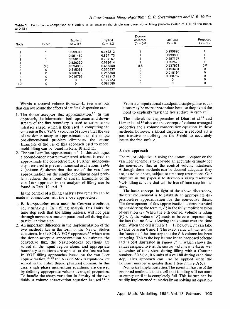
Problem 1: Injection molding of a plate casting. Consider a vertical thin plate casting (0.1016 x 0.1524 m2) filled through two 0.0127 m gates located in the lower corners (Figure 5). The molten metal (aluminum alloy) enters the casting at a constant velocity of 15.8496 m/s. The air inside is allowed to compress. The flow is assumed to be laminar and Newtonian. This problem is identical to the problem solved by Minaie et a1.25 using a SOLA-VOF approach. The density and viscosity of the two fluids are given in Table 2.
The performance of the proposed method is compared with both the donor-acceptor and the van Leer ap- proaches to this problem. In these latter approaches, the VOF equation is solved by explicit subcycling, i.e., the momentum and volume continuity equations are solved
Appl. Math. Modelling, 1994, Vol. 18, February 105
A time-implicit filling algorithm: C. R. Swaminathan an%’ J. R. Voller
I 0.1524 m
I 9’
b- 0.1016 m -4
Figure 5. Injection molding of a thin plate casting: problem specification.
[a) Donor-Acceptor
Table 2. Thermophysical properties of air and molten aluminum alloy at 750 “C
Material Density, kg/m3 Viscosity, kg/m/s
Air Aluminum alloy
0.35 4.0 x 10-s 2500 2.5 x lO-3
implicitly using a large time step and the VOF equation is solved explicitly a number of times within this large time step using interpolated velocities.
Different grid densities as well as time steps were tried out to ensure that the solution was grid as well as time step independent. The solution was carried out on a 32 x 48 uniform grid of cells. When using the donor- acceptor and van Leer approaches, the maximum Cr is fixed at 0.1 and the VOF equation is subcycled 10 times within each momentum and volume continuity step. This choice of Cr and the number of subcycles was found to be near optimal in terms of accuracy and efficiency. In the proposed approach, a constant time step of 0.002 s (corresponding to an average Cr of 14) is used. The solution is progressed till 0.025 s. The momentum equa- tions were underrelaxed by a factor of 0.75. A stringent mass and volume imbalance criteria of 10m5 and 10e4
(b) van Leer
(c) Proposed
Figure 6. Injection molding of a thin plate casting: prediction of the free surface location at intermediate times using (a) the donor- acceptor scheme, (b) the van Leer scheme, and (c) the proposed scheme.
is used to monitor the convergence during each time step. The number of time steps, iterations, and the CPU seconds on an IRIS workstation are summarized in Table 3. The proposed method is clearly more efficient than both the donor-acceptor and the van Leer methods. The extent of filling (plots of the F = 0.5 line) predicted at four intermediate times is shown in Figure 6. The donor- acceptor results show a slight loss of symmetry and also some unrealistic perturbations on the interface. The van Leer results, due to the slight smearing in the F field are much smoother. The results of the proposed scheme compare well qualitatively with both the donor-acceptor and the van Leer results. There are no unrealistic pertur- bations nor any smearing in the F field. Notice, however, that there is some fattening of the flow in the lower half where the two streams meet.
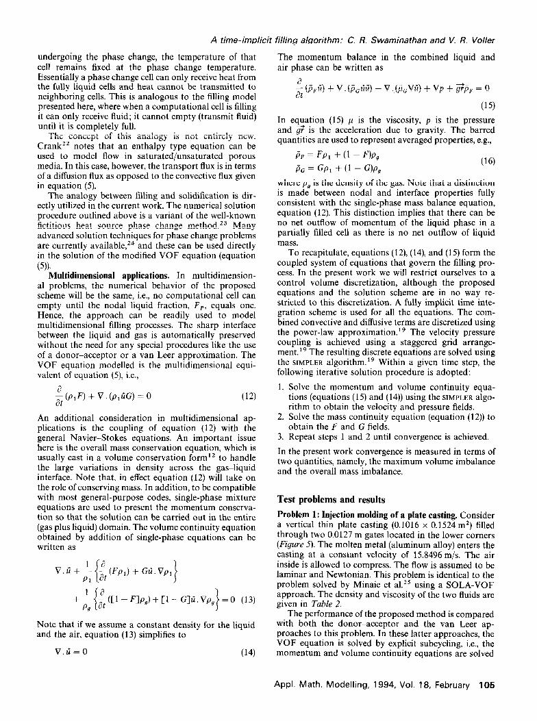
Problem 2: Wheel casting. This problem is included here to show how a reasonably complex shape can be modelled. Figure 7 shows the wheel casting along with the computational grid used. It is bottom filled against
Table 3. Performance comparison of the three methods on the injection molding problem
Method
Donor-acceptor van Leer Proposed
Courant no.
10 cycles @ 0.1 10 cycles @ 0.1 13.74 At = 0.002 s
No. of time steps
173 187
12
No. of iterations
1119 731 232
CPU,s on IRIS
273.3 219.8
58.7
106 Appl. Math. Modelling, 1994, Vol. 18, February

A rime-implicir filling algorirhm: C. R. Swaminathan and V. R. Voller
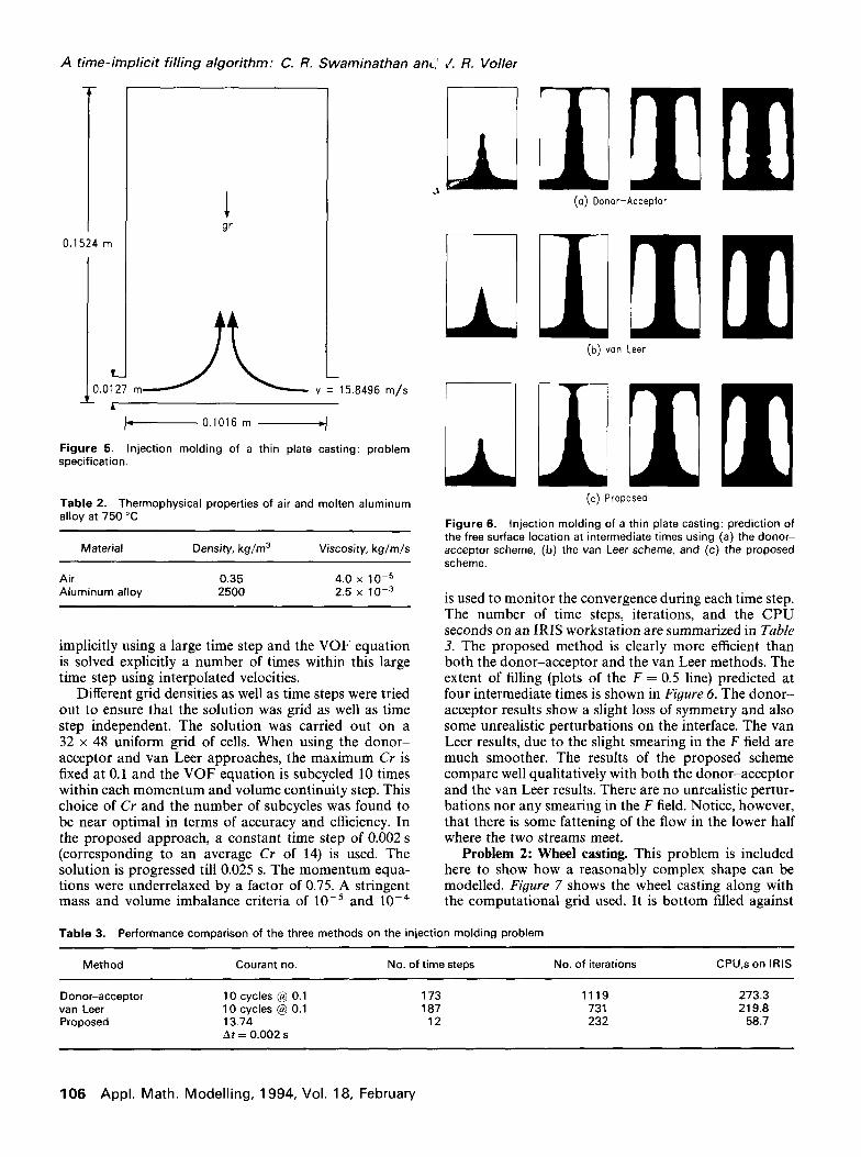
1.267 s 1.651 s 2.076 s 2.551 s
3.126 s 3.851 s 5.376 s
Figure 8. Filling of a wheel casting: prediction of the free surface location in 10% volume intervals using the proposed approach.
b- 0.1270 m -4
ta- 0.1778 m -4
ts- 0.1905 m -4
Figure 7. Filling of a wheel casting: problem specification and mesh used.
gravity through a 0.00635 m gate. The air is allowed to escape through a 0.00635 m vent at the top of the casting. The filling stage lasts 5.376 s. The inlet velocity is as- sumed to vary linearly with time. The density and viscos- ity for the two fluids are the same as in the previous problem. Exploiting symmetry, the solution is carried out on a 30 x 60 uniform grid of cells. Variable time stepping is used such that 5 cells are filled over each time step. The momentum equations are underrelaxed by a factor of 0.25.
The scheme requires, on an average, 18 iterations per time step to converge to a mass and volume imbalance
criteria of 10m5. Figure 8 shows the progress of filling in 10% volume intervals. The molten metal fills the center spoke before entering the rim. As time progresses, the rim starts filling and the molten metal rises into the hub as a jet and hits the central core. When this happens, the molten metal falls over and starts filling the remainder of the hub. It fills around this central core and overflows into the rising fluid in the rim. After this the mold fills almost as a plane front.
empty (i.e., problems involving sloshing) are outside of the current domain of the proposed method. In a given computation involving the method, a tendency for sloshing can be identified on checking changes in the G field over a time step. A reduction in the nodal G value (G < Gold) indicates a tendency to slosh. It is recommended that such a check along with appropri- ate flagging be used each time the method is imple- mented. It is worthwhile to note that in all of the above test runs the sloshing flag was never activated.
2. Jetting. In some filling problems the fluid forms a thin jet. This behavior will be most noticeable in the region of the ingate and at sharp corners. Depending on the numerical grid density this behavior could be missed by the proposed method. Once again the problem stems from the fact that cells have to be completely filled before they can communicate fluid. This means that a situation that “stacks” partially filled cells (as required in a jet) cannot be predicted. This inability to handle thin jets is a probable cause of the fattening noted in the flow of Problem 1 (Figure 6). The obvious way around a jetting problem is to use a finer grid in the viscinity of the jet. The effect of such a grid in decreasing the fattening effects is demonstrated in Figure 9.
Limitations of the proposed method
There are two potential limitations to the proposed filling method:
1. Sloshing. Due to the relationship between F and G, once a computational cell is full (i.e., F, = l), it cannot empty again. Consequently, problems in which re- gions of the mold cavity that fill and subsequently
Means of ensuring a sharp interface between the liquid metal and air in numerical calculations of the VOF equation have been outlined. A new scheme for estima- ting the convective fluxes at control volume interfaces has been proposed. Using this scheme along with a fully implicit control volume discretization, an efficient num- erical filling solution, free of the Courant condition, has been developed. The resulting numerical predictions are
Appl. Math. Modelling. 1994, Vol. 18, February 107

A rime-implicit filling algorirhm: C. R. Swaminathan and V, R. Voller
Figure 9. The proposed scheme solved on two different grids shows how the fattening phenomena can be minimized by proper grid choice.
smear-free and compare well with previous VOF solu- tions presented in the literature. A major feature of the proposed method is that it can be readily implemented in existing general purpose Navier-Stokes solvers with little additional work. This feature greatly enhances the utility of the proposed method. Further, it will mean that the modelling of general casting problems associated with complex phase change processes that involve filling and additional coupled phenomena (e.g., solidification, segregation, etc.) will be tractable. The results presented here clearly demonstrate the robustness of the proposed approach. Additional testing and development are underway, and we are currently working on problems that involve coupled filling and solidification. Work is also being directed at extending the concepts in the proposed method to problems that involve sloshing.
Acknowledgment
This work was supported by the National Center for Excellence in Metalworking Technology, operated by Concurrent Technologies Corporation, Johnstown, PA, under contract to the U.S. Navy as part of the U.S. Navy Manufacturing Technology Program. The authors would also like to acknowledge Professor S. V. Patankar
and Dr. Kanchan Kelkar for useful discussions and input and the Minnesota Supercomputer Institute for a com- puter resources grant.
References
1
2
3
4
5
6
14
15
16
17
18
19
20
21
22
23
24
25
Brody, H. D. and Apelian, D., eds. Conference Proceedings on the Modeling of Casting and Welding Processes, TMS-AIME, Warren- dale, PA, 1981 Berry, J. T. and Dantzig, J. A., eds. Conference Proceedings on the Modeling of Casting and Welding Processes, Vol. II, TMS-AIME, Warrendale, PA, 1984 Kou, S. and Mehrabian, R., eds. Conference Proceedings on the Modeling of Casting and Welding Processes, Vol. III, TMS-AIME, Warrendale, PA, 1987 Giamei, E. and Abbaschian, G. J., eds. Conference Proceedings on the Modeling of Casting and Welding Processes, Vol. IV, TMS- AIME, Warrendale, PA, 1989 Rappaz, M., Ozgu, M., and Mahin, K., eds. Conference Proceed- ings on the Modeling of Casting and Welding Processes, Vol. V, TMS-AIME, Warrendale, PA, 1991 Piwonka, T. S., Voller, V., and Katgerman, L., eds. Conference Proceedings on the Modeling of Casting and Welding Processes, Vol. VI, TMS-AIME, Warrendale, PA, 1993 Hwang, W. S. and Stoehr, R. A. Fluid flow modeling for computer aided design of castings. J. Metals 1983, 35, 22-29 Hwang, W. S. and Stoehr, R. A. Computer simulation for the filling of casting. AFS Trans. 1987,95,425430 Hwang, W. S. and Stoehr, R. A. Molten metal flow pattern prediction for complete solidification analysis of near net shape castings. Mat. Sci. Technol. 1988, 4. 24&250 Lin, H. J. and Hwang, W. S. Combined fluid flow and heat transfer analysis for the filling of castings. AFS Trans. 1988, 96, 447-458 Stoehr, R. A. and Wang, C. Coupled heat transfer and fluid flow in the filling of castings. AFS Trans. 1988,96, 733-740 Jun Liu and Spalding, D. B. Numerical simulation of flows with moving interfaces. PhysicoChem. Hydrodyn. 1988, 10, 625-637 Chan, K. S., Pericleous, K., and Cross, M. Numerical simulation of flows encountered during mould-filling. Appl. Math. Modelling 1991, 15, 624631 Dhatt, G., Gao, D. M., and Ben Cheikh, A. A finite element simulation of metal flow in moulds. Int. J. Numer. Methods Eng. 1990, 30, 821-831 Usmani, A. S., Cross, J. T., and Lewis, R. W. A finite element model for the simulations of mould filling in metal casting and the asso- ciated heat transfer. Int. J. Numer. Methods Eng. 1992,35,787-806 Zienkiewicz, 0. C. and Taylor, R. L. The Finite Element Method, Vol. 2, 4th ed. McGraw Hill Book Co., New York, 1992 Bellet, M. and Chenot, J. L. A Lagrangian approach to fluid flow in metal casting processes. Computational Methods for Free and Moving Boundary Problems in Heat and Fluid Flow, eds. L. C. Wrobel and C. A. Brebbia. Elsevier Applied Science, London, 1993 Hirt, C. W. and Nichols, B. D. Volume of fluid (VOF) method for the dynamics of free boundaries. J. Comput. Phys. 1981, 39, 201-225 Patankar, S. V. Numerical Heat Transfer and Fluid Flow. McGraw Hill Book Co., New York, 1980 Ramshaw, J. D. and Trapp, J. A. A numerical technique for low speed homogeneous two-phase flow with sharp interfaces. J. Com- put. Phys. 1976, 21, 4388445 van Leer, B. Towards the ultimate conservative difference scheme IV: A new approach to numerical convection. J. Comput. Phys. 1977, 23, 276299 Crank, J. Free and Moving Boundary Problems. Clarendon Press, Oxford, 1984 Rolph III, W. D. and Bathe, K. J. An efficient algorithm for analysis of nonlinear heat transfer with phase change. Int. J. Numer. Methods Eng. 1982, 18, 119-134 Swaminathan, C. R. and Voller, V. R. On the Enthalpy Method. Int. J. Numer. Methods Heat Fluid Flow 1993, 3, 233-244 Minaie, B., Stelson, K., and Voller, V. R. Analysis and flow patterns and solidification phenomena in die casting processes. J. Eng. Mech. Technol. ASME, 1991, 113,296302
108 Appl. Math. Modelling, 1994, Vol. 18, February