
A Thermo-hydrodynamic lubrication model of a mechanical ...
9
REGULAR ARTICLE A Thermo-hydrodynamic lubrication model of a mechanical seal modified by equivalent film thickness Xiuying Wang 1,* , Dapeng Zhi 2 , Chengtao Yu 1 , and Yu Chen 1 1 School of Mechanical Engineering, Jiangsu University of Technology, Changzhou 213000, PR China 2 School of Computer Engineering, Jiangsu University of Technology, Changzhou 213000, PR China Received: 1 August 2020 / Accepted: 6 December 2020 Abstract. An effective way to improve the combined performance of mechanical seals is to optimize their surface textures using multi-objective optimization method. For compatibility with the multi-objective optimization algorithm, the theoretical performance of a mechanical seal is often determined using the finite- difference method (FDM). However, compared with the finite-volume method (FVM) and finite-element method (FEM), FDM is weaker for dealing with the issue of discontinuous film thickness for a textured surface. In the present study, the thermo-hydrodynamic lubrication model of a mechanical seal is modified by means of an equivalent-thickness treatment, and the accuracy of the modified lubrication model is assessed by comparing its predictions for film pressure and temperature with published FVM and FEM results, showing that the equivalent-thickness lubrication model is effective for addressing the issue of discontinuous film thickness. The present work is important in that it improves the simulation accuracy of multi-objective optimization for textured mechanical seals. Keywords: Mechanical seal / multi-objective optimization / surface texture / discontinuous film thickness / equivalent thickness 1 Introduction In rotating machinery, leaks are prevented using mechani- cal seals, which have been subjected to much work to reduce friction and wear as well as leaks. In tribology, a popular method for reducing friction and wear is surface texturing [1–5], which has also received extensive attention in the context of mechanical seals. However, a surface texture with low friction or high opening force often results in a high rate of leakage [3–5], which is due to the produced opening force increasing the clearance available to the mechanical seal rings, thereby increasing the leakage [5]. Siripuram and Stephens [4] found that, for positive asperity, maximum leakage to occur at an asperity area fraction of 0.2, at which the friction coefficient is minimum; for negative asperity, the leakage tends to increase with decreasing friction coefficient. To address this contradiction between friction and leakage, Wang et al. [3,6] used multi-objective optimiza- tion to obtain an optimal texture based on an asymmetric “V” shape that differed from the optimal shape obtained using single-objective optimization [7,8]. That work inspired the texture optimization of mechanical compo- nents with more than one important performance parame- ter, but the multi-objective optimization research on surface textures that has been reported to date has solved for the performance parameters using greatly simplified control equations, such as by ignoring thermal and film- discontinuity effects, thereby producing inevitably less- accurate optimization results. Thermal effects are important when simulating a textured mechanical seal using a lubrication model [9–14]. Work based on a simplified energy equation under adiabatic conditions and with a constant temperature across the thickness of the film showed that the viscosity- thermal effect is important for slider and stepped bearing [13,14]. Khonsari [15,16] summarized early works on thermal effects in journal bearings and noted that most of the existing analytical solutions are based on simplified assumptions with questionable validity. A recent review by Sivakumar et al. [17] concluded that the thermal effects have a strong influence on the film thickness and pressure, and that thermal behavior is affected greatly by speed. It has also been noted that a temperature difference across the film, known as the “viscosity wedge” effect, has a * e-mail: [email protected] Mechanics & Industry 21, 622 (2020) © AFM, EDP Sciences 2021 https://doi.org/10.1051/meca/2020096 Mechanics & Industry Available online at: www.mechanics-industry.org
Transcript of A Thermo-hydrodynamic lubrication model of a mechanical ...

Mechanics & Industry 21, 622 (2020)© AFM, EDP Sciences 2021https://doi.org/10.1051/meca/2020096
Mechanics&IndustryAvailable online at:
www.mechanics-industry.org
REGULAR ARTICLE
A Thermo-hydrodynamic lubrication model of a mechanical sealmodified by equivalent film thicknessXiuying Wang1,*, Dapeng Zhi2, Chengtao Yu1, and Yu Chen1
1 School of Mechanical Engineering, Jiangsu University of Technology, Changzhou 213000, PR China2 School of Computer Engineering, Jiangsu University of Technology, Changzhou 213000, PR China
* e-mail: w
Received: 1 August 2020 / Accepted: 6 December 2020
Abstract. An effective way to improve the combined performance of mechanical seals is to optimize theirsurface textures using multi-objective optimization method. For compatibility with the multi-objectiveoptimization algorithm, the theoretical performance of a mechanical seal is often determined using the finite-difference method (FDM). However, compared with the finite-volume method (FVM) and finite-elementmethod (FEM), FDM is weaker for dealing with the issue of discontinuous film thickness for a textured surface.In the present study, the thermo-hydrodynamic lubrication model of a mechanical seal is modified by means ofan equivalent-thickness treatment, and the accuracy of the modified lubrication model is assessed by comparingits predictions for film pressure and temperature with published FVM and FEM results, showing that theequivalent-thickness lubrication model is effective for addressing the issue of discontinuous film thickness. Thepresent work is important in that it improves the simulation accuracy of multi-objective optimization fortextured mechanical seals.
Keywords: Mechanical seal / multi-objective optimization / surface texture / discontinuous film thickness /equivalent thickness
1 Introduction
In rotating machinery, leaks are prevented using mechani-cal seals, which have been subjected to much work toreduce friction and wear as well as leaks. In tribology, apopular method for reducing friction and wear is surfacetexturing [1–5], which has also received extensive attentionin the context of mechanical seals. However, a surfacetexture with low friction or high opening force often resultsin a high rate of leakage [3–5], which is due to the producedopening force increasing the clearance available to themechanical seal rings, thereby increasing the leakage [5].Siripuram and Stephens [4] found that, for positiveasperity, maximum leakage to occur at an asperity areafraction of 0.2, at which the friction coefficient is minimum;for negative asperity, the leakage tends to increase withdecreasing friction coefficient.
To address this contradiction between friction andleakage, Wang et al. [3,6] used multi-objective optimiza-tion to obtain an optimal texture based on an asymmetric
“V” shape that differed from the optimal shape obtainedusing single-objective optimization [7,8]. That workinspired the texture optimization of mechanical compo-nents with more than one important performance parame-ter, but the multi-objective optimization research onsurface textures that has been reported to date has solvedfor the performance parameters using greatly simplifiedcontrol equations, such as by ignoring thermal and film-discontinuity effects, thereby producing inevitably less-accurate optimization results.
Thermal effects are important when simulating atextured mechanical seal using a lubrication model[9–14]. Work based on a simplified energy equation underadiabatic conditions and with a constant temperatureacross the thickness of the film showed that the viscosity-thermal effect is important for slider and stepped bearing[13,14]. Khonsari [15,16] summarized early works onthermal effects in journal bearings and noted that mostof the existing analytical solutions are based on simplifiedassumptions with questionable validity. A recent review bySivakumar et al. [17] concluded that the thermal effectshave a strong influence on the film thickness and pressure,and that thermal behavior is affected greatly by speed. Ithas also been noted that a temperature difference acrossthe film, known as the “viscosity wedge” effect, has a

Fig. 1. Model of lubrication with textured surface.
Fig. 2. Model of textured mechanical seal.
2 X. Wang et al.: Mechanics & Industry 21, 622 (2020)
significant effect on the load-carrying capacity [18,19]. Theabove analysis suggests that considering viscosity-thermaleffect may lead to more-accurate multi-objective optimi-zation of surface textures on mechanical seals.
For lubricationmodels involving a textured surface, theproblem of film thickness discontinuity often occurs.Figure 1 shows a typical case in which a dimpled surfacedivides the fluid film into two regions, namely A and B, thefilm thickness discontinuity occurs at the boundarybetween regions A and B. The finite-volume method(FVM) and finite-element method (FEM) are powerfultools for addressing this issue [20–23]. For instance, Millerand Green [22,23] used the FVM and FEM successfully todeal with the film thickness discontinuity in spiral-groovedface seals. Although finite-difference method (FDM) isweaker to deal with the film thickness discontinuity, it canalso address this issue if the region of film thicknessdiscontinuous is subjected to special treatment. Forinstance, Chen et al. [24] used an eight-point discrete gridto approximate the gradient of film thickness, and Ogataet al. [25] provided an algorithm by defining equivalentclearance height and its gradient in the region ofdiscontinuous film thickness in a two-dimensional stepbearing. However, for the multi-objective optimization oftextured mechanical seals, the FVM and FEM are not easyreadily compatible with the multi-objective optimizationalgorithm. Instead, the lubrication model in references [3]and [6] must be modified to improve the FDM calculationaccuracy.
Herein, a three-dimensional lubrication model ispresented that considers film thickness discontinuityand thermal effects. Inspired by reference [25], the filmthickness discontinuity is treated by defining andequivalent film thickness and its gradient. The lubricationmodel considers heat dissipation by convection. Themodified lubrication model is then used to calculate thedistributions of pressure and temperature, and itsaccuracy is assessed by comparison with published results.The present work is important in that it will improve thesimulation accuracy in future multi-objective optimiza-tions of textured mechanical seals.
2 Thermo-hydrodynamic lubrication model
2.1 Reynolds equation
Figure 2 shows a model of a textured mechanical seal. Byselecting a periodic texture area, the computationaldomain is simplified to a rectangular one. The pressuredistribution in the fluid film is obtained by solving the
Reynolds equation in the form
∂∂x
rh3
h
∂p∂x
� �þ ∂∂y
rh3
h
∂p∂y
� �¼ 6u
∂rh∂x
; ð1Þ
while the effect of temperature on viscosity is consideredusing the Barus equation in the form
h ¼ h0e�bðt�t0Þ: ð2Þ
By the dimensionless criterion, equations (1) and (2)are expressed in dimensionless form respectively as
∂∂X
H3
h
∂P∂X
� �þ ∂∂Y
H3
h
∂P∂Y
� �¼ ∂H
∂X; ð3Þ
h ¼ e�bðt�t0Þ; ð4ÞThe dimensionless Reynolds equation (3) is written as
∂2P∂X2
þ 3
H
∂H∂X
� 1
h
∂h∂X
!∂P∂X
þ ∂2P∂Y 2
þ 3
H
∂H∂Y
� 1
h
∂h∂Y
!∂P∂Y
¼ h
H3
∂H∂X
;
ð5Þ
where X ¼ x
a;Y ¼ y
a;H ¼ h
h0;P ¼ h2
0
6uh0ap; h ¼ h
h0. Here,
u is the velocity, h is the dynamic viscosity of lubrication,h0 is the viscosity at the temperature t0, b is the viscosity-thermal coefficient, and h0 is the minimum thickness oflubrication film. The calculation domain is a square withside length a, the inner and outer boundary pressures arepinner and pouter, and periodic boundaries are applied toaccount for the interaction between textures. In thecavitation regions, the pressure is set to zero accordingtoReynolds cavitation condition. In the region of continuousfilm thickness, the dimensionless Reynolds equation isdiscretized using a central differential in the form of
∂P∂X
����i;j
¼ Piþ1;j � Pi�1;j
2DX;∂2P∂X2
����i;j
¼ Piþ1;j � 2Pi;j þ Pi�1;j
ðDXÞ2 ;
∂P∂Y
����i;j
¼ Pi;jþ1 � Pi;j�1
2DY;∂2P∂Y 2
����i;j
¼ Pi;jþ1 � 2Pi;j þ Pi;j�1
ðDY Þ2 ;
ð6Þ

X. Wang et al.: Mechanics & Industry 21, 622 (2020) 3
from which the differencing equation of Pi,j is obtained as
See equation (7) below
2.2 Equivalent thickness model
The film thickness is discontinuous where the texturedand non-textured regions meet. This issue is addressedusinga two-dimensional equivalent thicknessmodel inspiredby the one-dimensional equivalent clearance model inreference [25]. In the x and y directions, the respective flowequations are
qx ¼ uh
2� h3
12h
∂p∂x
;
qy ¼ � h3
12h
∂p∂y
;
ð8Þ
which in dimensionless form are
QX ¼ H �H3
h
∂P∂X
;
QY ¼ �H3
h
∂P∂Y
;
ð9Þ
where QX ¼ qxuh0=2
;QY ¼ qyuh0=2
. Suppose that node (i, j)
is a point of discontinuous film thickness. The continuityequations of fluid are
QXjiþ1;j ¼ QXji�1;j;QY ji;jþ1 ¼ QY ji;j�1; ð10Þ
and equation (9) is discretized by an upwind and downwinddifferential scheme at the region of discontinuous film
Pi;j ¼ ðDY Þ22ððDXÞ2 þ ðDY Þ2Þ þ
DXðDY Þ24ððDXÞ2 þ ðDY
"
þ ðDY Þ22ððDXÞ2 þ ðDY Þ2Þ �
DXðDY Þ24ððDXÞ2 þ ðDY
"
þ ðDXÞ22ððDXÞ2 þ ðDY Þ2Þ þ
ðDXÞ2DY4ððDXÞ2 þ ðDY
"
þ ðDXÞ22ððDXÞ2 þ ðDY Þ2Þ �
ðDXÞ2DY4ððDXÞ2 þ ðDY
"
� ðDXÞ2ðDY Þ22ððDXÞ2 þ ðDY Þ2Þ
hi;j
H3i;j
∂H∂X
����i;j
:
thickness, namely
∂P∂X
����iþ1;j
¼ Piþ1;j � Pi;j
DX;
∂P∂X
����i�1;j
¼ Pi;j � Pi�1;j
DX;
∂P∂Y
����i;jþ1
¼ Pi;jþ1 � Pi;j
DY;
∂P∂Y
����i;j�1
¼ Pi;j � Pi;j�1
DY:
ð11Þ
Then, according to equations (10) and (11), thedifferencing equation for Pi,j is obtained as
Pi;j ¼hi�1;jH
3iþ1;j
2ðhi�1;jH3iþ1;j þ hiþ1;jH
3i�1;jÞ
Piþ1;j
þ hiþ1;jH3i�1;j
2ðhi�1;jH3iþ1;j þ hiþ1;jH
3i�1;jÞ
Pi�1;j
þ hi;j�1H3i;jþ1
2ðhi;j�1H3i;jþ1 þ hi;jþ1H
3i;j�1Þ
Pi;jþ1
þ hi;jþ1H3i;j�1
2ðhi;j�1H3i;jþ1 þ hi;jþ1H
3i;j�1Þ
Pi;j�1
� ðHiþ1;j �Hi�1;jÞhiþ1;jhi�1;jDX
2ðhi�1;jH3iþ1;j þ hiþ1;jH
3i�1;jÞ
:
ð12Þ
Comparing equations (7) and (12) shows that theexpressions for Pi, j are different for the continuous and
Þ2Þ3
Hi;j
∂H∂X
����i;j
� 1
hi;j
∂h∂X
����i;j
!#Piþ1;j
Þ2Þ3
Hi;j
∂H∂X
����i;j
� 1
hi;j
∂h∂X
����i;j
!#Pi�1;j
Þ2Þ3
Hi;j
∂H∂Y
����i;j
� 1
hi;j
∂h∂Y
����i;j
!#Pi;jþ1
Þ2Þ3
Hi;j
∂H∂Y
����i;j
� 1
hi;j
∂h∂Y
����i;j
!#Pi;j�1
ð7Þ

4 X. Wang et al.: Mechanics & Industry 21, 622 (2020)
discontinuous regions. The equivalent thickness and itsgradient are obtained by solving
See equation (13) below
which were obtained by defining the constant term and thecorresponding coefficients of Pi+1, j, Pi�1, j, Pi, j+1 and Pi,j�1be equal in equations (7) and (12), respectively. The newequation
See equation (14) below
were obtained by subtracting equation (13-1) and equation(13-3), equation (13-4) and equation (13-5), respectively.Equation (15-1) was obtained by dividing equation (14-2)by equation (14-1), while equation (15-2) and (15-3)were obtained by substituting equation (15-1) intoequation (14-2) and equation (14-3), respectively:
See equation (15) below
By using equation (15) to redefine Hi,j, (∂H/∂X)|i,jand (∂H/∂Y)|i,j in the discontinuous regions, equation(7) becomes true for the entire calculation domainincluding continuous and discontinuous regions. Thisthen allows the Reynolds equation to be solved using theFDM.
2.3 Energy equation
For hydrodynamic lubrication state, it is regarded as anadiabatic process in order to simplify the procedures in thisstudy. In fact, the viscous heat generated in the fluid isdissipated through the fluid film, into the nearby solids.The entire field of thermo-elasto-hydrodynamic lubricationdeals with this phenomenon.More details can be seen in thework by Srivastava et al. [11]. The temperature, pressureand viscosity are assumed to remain constant in the filmthickness direction, then a simplified energy equation is
ð13Þ
ð14Þ
ð15Þ

Fig. 3. Flowchart of procedure.
X. Wang et al.: Mechanics & Industry 21, 622 (2020) 5
obtained in the form
qx∂t∂x
þ qy∂t∂y
¼ hu2
rcrhþ h3
12hrcr
∂p∂x
� �2
þ ∂p∂y
� �2" #
; ð16Þ
where qx and qy are the volume flows in the x and ydirections, respectively, r is the fluid density, and cr is thespecific heat of lubricant. The dimensionless energy equationis
QX
∂T∂X
þQY
∂T∂Y
¼ 4h
Hþ 12H3
h
" ∂P∂X
!2
þ ∂P∂Y
!2#; ð17Þ
where T ¼ 2rcrh20
uah0t;QX ¼ H �H3
h
∂P∂X
;QY ¼ �H3
h
∂P∂Y
.
To assess the accuracy of the equivalent film thicknessmodel and the program calculation in the present study,the dimensionless load-carrying capacity W, the dimen-sionless pressure P, the dimensionless temperature T areobtained as performance parameters by using FDM tosolve the above equations. The dimensionless load-carryingcapacity W is defined as the integral of the dimensionlesspressureP in the dimensionless calculation domain, namely
W ¼Z 1
0
Z 1
0
PdXdY ð18Þ
The performance parameters were calculated using theprocedure shown in Figure 3. The number of nodes was1000� 1000 for the lubrication model.
Fig. 4. Model of inclined surface.
3 Accuracy assessment
3.1 Inclined surface model
For an inclined surface as shown in Figure 4, the filmthickness is continuous and does not require specialtreatment using equation (15). To assess the accuracy ofthe lubrication model for continuous film thickness, itscalculated values are compared with the results obtainedby Raimondi [13].
In the present study, the parameter values that areused for the lubricating oil are the same as those inreference [13], namely t0= 100 °F, h0= 8.16� 10�6 lb s/in.2,r=0.0312 lb/in.3, cv=cr=4435 in./°F, where the param-eter values are given in non-standard units for consistencywith the quoted reference. The viscosity h= h0e
�b(t�t0) isapplied, and b=0.02342 is obtained by curve fitting usingthe values of viscosity and temperature given in Table 1 inreference [13] (the tables and figures in the references arequoted in all capitals in order to distinguish them from thispaper, the same below). The density is treated as beingconstant of 0.0312 lb/in.3 because it changes little withinthe temperature range used in reference [13]. The film

Table 1. Results from Raimondi [13] and present approach.
Conditions Raimondi [13] Present approach
h1/h2 10�4Vp ðpsiÞ DT pmaxBL
WDT pmaxBL
W
1.4 10 0.0921 2.05 0.0932 1.9822 10 0.0784 2.07 0.0838 2.0803 10 0.0667 2.32 0.0683 2.2664 10 0.0600 2.46 0.0556 2.5332 1 0.156 2.23 0.1548 2.2442 3 0.123 2.16 0.1250 2.1632 30 0.0461 2.00 0.0446 1.915
Table 2. Results from Dobrica and Fillon [21] and present approach.
Conditions Dobrica and Fillon Present approach
Tmax (°C) Load capacity (kN) Tmax (°C) Load capacity (kN)
LP = 66%L, BP = 80%B 38 97.1 36.2 89.7LP = 30%L, BP = 30%B 10 94.6 9.7 86.2
6 X. Wang et al.: Mechanics & Industry 21, 622 (2020)
thickness h and the dimensionless film thickness H areexpressed as
h ¼ h2 þB� x
Bðh1 � h2Þ;
H ¼ h
h2¼ 1þB� x
B
h1
h2� 1
� �;
ð19Þ
and two parameters used in reference [13] are defined as
Vp ¼ 6h0uB
h22
;
DT ¼ Dtrcvh22
6h0uB:
ð20Þ
With the above parameter values, equations (1) and (16)are solved using the FDM for B/L=1, with DT andpmaxBL/W (i.e. pmax/P in Ref. [13]) calculated undervarious working conditions. The results calculated byRaimondi are taken directly from Table 2 in reference [13].Herein, Table 1 gives the results obtained by the presentapproach and Raimondi, from which the errors in DT andpmaxBL/W are calculated using
Error ¼ jPresent result� Reference’s resultjjReference’s resultj � 100%
ð21ÞFigure 5 compares the present and published results for
10�4Vp=10 psi. As can be seen, within the range ofparameter values studied, themaximum error inDT (7.3%)occurs at h1/h2= 4.0 and the maximum error in pmaxBL/W(3.3%) occurs at h1/h2= 1.4. Meanwhile, the manner in
which the errors vary with h1/h2 shows no obvious trendand instead can be considered as random. In general, theerrors between the present method and that in reference[13] are very small in most cases.
Figure 6 compares the present and published results forh1/h2= 2. As can be seen, within the range of parametervalues studied, the maximum error in DT (7.7%) occurs at10�4Vp=10 psi and the maximum error in pmaxBL/W(4.3%) occurs at 10�4Vp=30 psi. Meanwhile, the mannerin which the errors vary with 10�4Vp shows no obvioustrend and instead can be considered as random. Combiningthe errors in Figures 5 and 6 the maximum error is only7.7%within the range of parameter values studied. The twoapproaches give different results under the same conditionsfor the following main reasons. (1) The results differslightly according to the meshing conditions. (2) The valueb=0.02342 is obtained by curve fitting using the values ofviscosity and temperature in Table 1 in reference [13], thecoefficient of determination of the curvefitting is 0.996, whichis close to but not equal to 1. Therefore, the viscosity valuesused in the present studydiffer slightly fromthose in reference[13]. (3) The Density is treated herein as a constant, which isslightly different from the treatment in reference [13].
Based on the above analysis, the results calculated inthe present study can be considered to agree well with thosein reference [13]. This means that the modified lubricationmethod in the present study can be used to solve theinclined surface model with high precision.
3.2 Stepped surface model
For a stepped surface, take as an example a pocket bearingas studied by Dobrica and Fillon [21]. Figure 7 shows thephysical model, for which the relevant parameter values are

Fig. 6. Comparison of present and published results for h1/h2= 2: (a) DT versus 10�4 (b) pmaxBL/W versus 10�4 Vp.
Fig. 5. Comparison of present and published results for 10�4Vp=10 psi: (a) DT versus h1/h2 (b) pmaxBL/W versus h1/h2.
Fig. 7. Model of stepped surface.
X. Wang et al.: Mechanics & Industry 21, 622 (2020) 7
the same as those in reference [21], namely L=0.08m,B=0.08m, hP=hI=20mm, r=860kg/m3, Cr=2000J/kg ·K. The viscosity-thermal coefficient b=0.0316 iscalculated from the viscosity values at 40 and 100 °C inreference [21]. The length LP and the width BP of the pocketarevariedbetween12%and87%oftheentirepad lengthLandwidth B, respectively. Based on these parameter values, thepressure distribution, maximum temperature and loadcapacity are obtained using the present procedure and thencompared with those obtained using the FVM in reference[21].
Themaximum load capacity is obtained for LP=66%L,BP=80%B. Figure 8 shows the pressure distributionsobtained using the present FDM and the FVM in reference[21]. As can be seen, the pressure distributions are veryclose and have similar distributions and close peaks. This
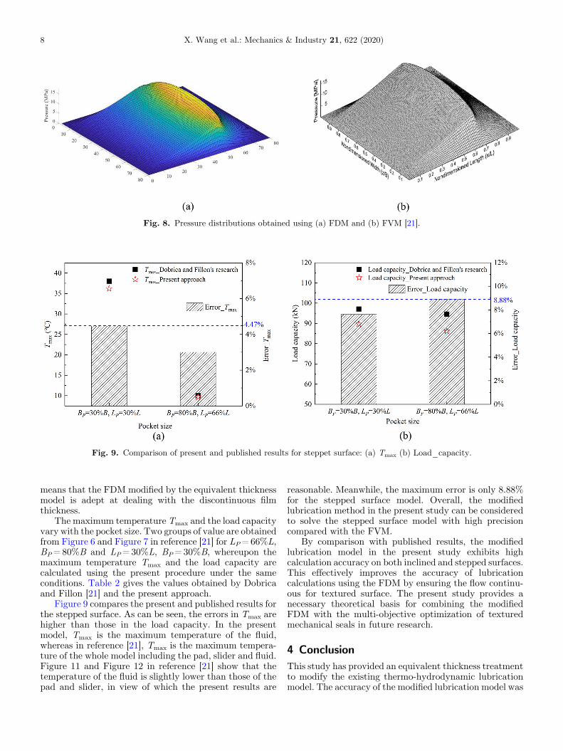
Fig. 9. Comparison of present and published results for steppet surface: (a) Tmax (b) Load_capacity.
Fig. 8. Pressure distributions obtained using (a) FDM and (b) FVM [21].
8 X. Wang et al.: Mechanics & Industry 21, 622 (2020)
means that the FDM modified by the equivalent thicknessmodel is adept at dealing with the discontinuous filmthickness.
The maximum temperature Tmax and the load capacityvary with the pocket size. Two groups of value are obtainedfrom Figure 6 and Figure 7 in reference [21] for LP=66%L,BP=80%B and LP=30%L, BP=30%B, whereupon themaximum temperature Tmax and the load capacity arecalculated using the present procedure under the sameconditions. Table 2 gives the values obtained by Dobricaand Fillon [21] and the present approach.
Figure 9 compares the present and published results forthe stepped surface. As can be seen, the errors in Tmax arehigher than those in the load capacity. In the presentmodel, Tmax is the maximum temperature of the fluid,whereas in reference [21], Tmax is the maximum tempera-ture of the whole model including the pad, slider and fluid.Figure 11 and Figure 12 in reference [21] show that thetemperature of the fluid is slightly lower than those of thepad and slider, in view of which the present results are
reasonable. Meanwhile, the maximum error is only 8.88%for the stepped surface model. Overall, the modifiedlubrication method in the present study can be consideredto solve the stepped surface model with high precisioncompared with the FVM.
By comparison with published results, the modifiedlubrication model in the present study exhibits highcalculation accuracy on both inclined and stepped surfaces.This effectively improves the accuracy of lubricationcalculations using the FDM by ensuring the flow continu-ous for textured surface. The present study provides anecessary theoretical basis for combining the modifiedFDM with the multi-objective optimization of texturedmechanical seals in future research.
4 ConclusionThis study has provided an equivalent thickness treatmentto modify the existing thermo-hydrodynamic lubricationmodel. The accuracy of the modified lubrication model was

X. Wang et al.: Mechanics & Industry 21, 622 (2020) 9
assessed by comparing the film pressure distribution,temperature and load capacity calculated using the FDMand published results obtained using the FVM and FEMfor models of inclined and stepped surfaces. Uponcomparison, the results agreed very well, meaning thatthe lubrication model modified by the equivalent thicknesstreatment addresses well the issue of discontinuous filmthickness when the FDM is applied. This work is importantin that it improves the simulation accuracy of multi-objective optimization of textured mechanical seals.
This work was supported by the Talent Introduction Foundationof Jiangsu University of Technology (No. KYY19001) and theNatural Science Foundation of the Jiangsu Higher EducationInstitutions of China (No. 19KJB460001).
References
[1] N. Brunetière, B. Tournerie, Numerical analysis of a surface-textured mechanical seal operating in mixed lubricationregime, Tribology International 49, 80–89 (2012)
[2] C.B. Khatri, S.C. Sharma, Performance of two-lobe hole-entry hybrid journal bearing system under the combinedinfluence of textured surface and couple stress lubricant,Mechanics & Industry 18, 603 (2017)
[3] X. Wang, L. Shi, W. Huang, X. Wang, A multi-objectiveoptimization approach on spiral grooves for gas mechanicalseals, Journal of Tribology 140, 041701-1-10 (2018)
[4] R.B. Siripuram, L.S. Stephens, Effect of deterministicasperity geometry on hydrodynamic lubrication, Journalof Tribology 126, 527–534 (2004)
[5] J. Sun, C. Ma, Q. Yu, J. Lu, M. Zhou, P. Zhou, Numericalanalysis on a new pump-out hydrodynamic mechanical seal,Tribology International 106, 62–70 (2017)
[6] X. Wang, L. Shi, Q. Dai, W. Huang, X. Wang, Multi-objective optimization on dimple shapes for gas face seals,Tribology International 123, 216–223 (2018)
[7] C. Shen, M. Khonsari, Texture shape optimization for seal-like parallel surfaces: theory and experiment, TribologyTransactions 59, 698–706 (2016)
[8] H. Zhang, M. Hua, G. Dong, D. Zhang, W. Chen, G. Dong,Optimization of texture shape based on genetic algorithmunder unidirectional sliding, Tribology International 115,222–232 (2017)
[9] S. Blasiak, The two dimensional thermohydrodynamicanalysis of a lubrication in non-contacting face seals, Journalof Thermal Science and Technology 10, 1–8 (2015)
[10] E. Galenne, I. Pierre-Danos, Thermo-elasto-hydro-dynamicmodeling of hydrostatic seals in reactor coolant pumps,Tribology Transactions 50, 466–476 (2007)
[11] G. Srivastava, P. Chiappa, J. Shelton, C. Fred Higgs III,A Thermo-elasto-hydrodynamic lubrication modelingapproach to the operation of reactor coolant pump seals.Tribology International 138, 487–498 (2019)
[12] N. Brunetière, B. Tournerie, J. Frěne, A simple and easy-to-use TEHD model for non-contacting liquid face seals,Tribology Transactions 46, 187–192 (2003)
[13] A.A. Raimondi, An adiabatic solution for the finite sliderbearing (L/B = 1), ASLE Transactions 9, 283–298 (1966)
[14] M. He, P. Allaire, C.H. Cloud, J. Nicholas, A pressure dambearing analysis with adiabatic thermal effects, TribologyTransactions 47, 70–76 (2004)
[15] M. Khonsari, A review of thermal effects in hydrodynamicbearings part I: slider and thrust bearings, ASLE Trans-actions 30, 19–25 (1987)
[16] M. Khonsari, A review of thermal effects in hydrodynamicbearings. Part II: Journal Bearings, ASLE Transactions 30,26–33 (1987)
[17] D. Sivakumar, S. Nagesh, K.N. Seetharamu, Review ofthermal, turbulent and misalignment effects on hydrody-namic, Journal Bearings 5, 303–308 (2019)
[18] X. Meng, M. Khonsari, Viscosity wedge effect of dimpledsurfaces considering cavitation effect, Tribology Interna-tional 122, 58–66 (2018)
[19] J. Cui, M. Kanet, P. Yang, P. Yang, The relation betweenthermal wedge and thermal boundary conditions for theload-carrying capacity of a rectangular pad and a slider withparallel gaps, Journal of Tribology 138, 024502-1-6 (2015)
[20] M.B. Dobrica, M. Fillon, Reynolds’ model suitability insimulating rayleigh step bearing thermohydrodynamicproblems, Tribology Transactions 48, 522–530 (2005)
[21] M.B. Dobrica, M. Fillon, Thermohydrodynamic behavior ofa slider pocket bearing, Journal of Tribology 128, 312–318(2006)
[22] B.A.Miller, I. Green, Numerical formulation for the dynamicanalysis of spiral-grooved gas face seals, Journal of Tribology123, 395–403 (2001)
[23] B.A. Miller, I. Green, Numerical techniques for computingrotordynamic properties of mechanical gas face seals, Journalof Tribology 124, 755–761 (2002)
[24] S. Chen, H. Chou, Y. Kang, Stability analysis of hydrody-namic bearing with herringbone grooved sleeve, TribologyInternational 55, 15–28 (2012)
[25] H. Ogata, J. Sugimura, Equivalent clearance model forsolving thermohydrodynamic lubrication of slider bearingswith steps, Journal of Tribology 139, 034503-1-5 (2016)
Cite this article as: X. Wang, D. Zhi, C. Yu, Y. Chen, A Thermo-hydrodynamic lubrication model of a mechanical seal modifiedby equivalent film thickness, Mechanics & Industry 21, 622 (2020)


