A Study on Laminar Pipe flow & losses - IJIETijiet.com/wp-content/uploads/2016/12/47.pdf · In...
7
International Journal of Innovations in Engineering and Technology (IJIET) 346 Volume 7 Issue 4 December 2016 ISSN: 2319 - 1058 A Study on Laminar Pipe flow & losses Prabir Chakraborty Final Year, Mechanical Engg. Department (B.E) RSR RCET, Bhilai, Chhattisgarh, India Devender Singh Final Year, Mechanical Engg. Department (B.E) RSR RCET, Bhilai, Chhattisgarh, India Himanshu Kumbhare Final Year, Mechanical Engg. Department (B.E) RSR RCET, Bhilai, Chhattisgarh, India Ankur Singh Final Year, Mechanical Engg. Department (B.E) RSR RCET, Bhilai, Chhattisgarh, India Abstract- This paper investigates some important works done on laminar flow in pipes. This review is focused on some of the important parameters to be considered in laminar flow; such as frictional losses, heat transfer etc. in laminar flow in pipes of different shapes, and the importance of laminar flow in its areas of applications. In some journals, the analysis was done on the pressure drop, some focused on friction factor analysis and heat transfer effects of laminar flow while some discussed its applications in various industries. In most of the journals, the flow was through circular pipes but in industries today some circular pipes have become elliptical in shape due to long time usage of the pipes, which would contribute to increase in some different forms of losses.This paper also includes the use of Bernoulli’s principle to calculate or recognize the losses occurring during the flow in pipes. I. INTRODUCTION In fluid dynamics, Bernoulli's principle states that an increase in the speed of a fluid occurs simultaneously with a decrease in pressure or a decrease in the fluid's potential energy. In a steady flow, the sum of all forms of energy in a fluid along a streamline is the same at all points on that streamline. This requires that the sum of kinetic energy, potential energy and internal energy remains constant. The Bernoulli equation can be considered to be a statement of the conservation of energy appropriate for flowing fluids. The qualitative behavior that is usually labeled with the term “Bernoulli effect” is the lowering of fluid pressure in regions where the flow velocity is increased. The energy form is written as follows. Each term has dimensions of energy per unit mass of fluid. We use the convention that location 1 is the inlet and location 2 is the outlet. P 1 / Ƿg + V 1 2 /2g + Z 1 = P 2 / Ƿg + V 2 2 /2g + Z 2 (1) Where, P 1 = Pressure at the inlet of pipe P 2 = Pressure at the outlet of pipe V 1 = Velocity of fluid at the inlet V 2 = Velocity of fluid at the outlet Z 1 = Datum at inlet Z 2 = Datum at outlet
Transcript of A Study on Laminar Pipe flow & losses - IJIETijiet.com/wp-content/uploads/2016/12/47.pdf · In...

International Journal of Innovations in Engineering and Technology (IJIET)
346
Volume 7 Issue 4 December 2016 ISSN: 2319 - 1058
A Study on Laminar Pipe flow & losses Prabir Chakraborty
Final Year, Mechanical Engg. Department (B.E) RSR RCET, Bhilai, Chhattisgarh, India
Devender Singh
Final Year, Mechanical Engg. Department (B.E) RSR RCET, Bhilai, Chhattisgarh, India
Himanshu Kumbhare
Final Year, Mechanical Engg. Department (B.E) RSR RCET, Bhilai, Chhattisgarh, India
Ankur Singh
Final Year, Mechanical Engg. Department (B.E) RSR RCET, Bhilai, Chhattisgarh, India
Abstract- This paper investigates some important works done on laminar flow in pipes. This review is focused on some of the important parameters to be considered in laminar flow; such as frictional losses, heat transfer etc. in laminar flow in pipes of different shapes, and the importance of laminar flow in its areas of applications. In some journals, the analysis was done on the pressure drop, some focused on friction factor analysis and heat transfer effects of laminar flow while some discussed its applications in various industries. In most of the journals, the flow was through circular pipes but in industries today some circular pipes have become elliptical in shape due to long time usage of the pipes, which would contribute to increase in some different forms of losses.This paper also includes the use of Bernoulli’s principle to calculate or recognize the losses occurring during the flow in pipes.
I. INTRODUCTION In fluid dynamics, Bernoulli's principle states that an increase in the speed of a fluid occurs simultaneously
with a decrease in pressure or a decrease in the fluid's potential energy. In a steady flow, the sum of all forms of energy in a fluid along a streamline is the same at all points on that streamline. This requires that the sum of kinetic energy, potential energy and internal energy remains constant.
The Bernoulli equation can be considered to be a statement of the conservation of energy appropriate for flowing fluids. The qualitative behavior that is usually labeled with the term “Bernoulli effect” is the lowering of fluid pressure in regions where the flow velocity is increased.
The energy form is written as follows. Each term has dimensions of energy per unit mass of fluid. We use the convention that location 1 is the inlet and location 2 is the outlet.
P1/ Ƿg + V12/2g + Z1 = P2/ Ƿg + V2
2/2g + Z2 (1) Where, P1 = Pressure at the inlet of pipe P2= Pressure at the outlet of pipe V1 = Velocity of fluid at the inlet V2 = Velocity of fluid at the outlet Z1= Datum at inlet Z2= Datum at outlet
International Journal of Innovations in Engineering and Technology (IJIET)
347
Volume 7 Issue 4 December 2016 ISSN: 2319 - 1058
Ƿ = Density of the fluid g = Acceleration due to gravity
Laminar flow is a gentle flow in which the streamlines are not crossing each other, that is, they are parallel to one another. A flow is said to be laminar in a pipe if the value of its Reynolds number is less than 2000.As the fluid flows through a pipe heat is generated and the flow pressure also reduces, this is due to the friction existing between the flow fluid and the wall of the pipe. Estimation of the value of the head loss is very important. A) Pipe losses
Most pipe systems consist of considerably more than straight pipes. These additional components add to the overall head loss of the system. Such losses are generally termed minor losses. The minor losses are greater than the major losses and are raised by – 1. Pipe entrance or exit 2. Sudden expansion or contraction 3. Bends, elbows, tees, and other fittings 4. Valves, open or partially closed 5. Gradual expansions or contractions Major losses are as follows–
Head loss in a pipe is affected by a number of factors which include the viscosity of the fluid, the size of the internal pipe diameter, the internal roughness of the inner surface of the pipe, the change in elevation between the ends of the pipe and the length of the pipe along which the fluid travels. In 2001, in the journal of Evaldo Miranda Coiado Victor Emanuel M.G. Diniz, the head losses values for the downward sloping pipes was always found to be lower than the head losses for the horizontal pipe, and these were always lower than the head losses for the upward sloping pipes, regardless the inclination angles and concentrations. Negative pressure values were obtained for the three tested concentrations, with inclination angles of 22.5°, 34° and 45°. [4] The Darcy formula or the Darcy-Weisbach equation as it tends to be referred to, is now accepted as the most accurate pipe friction loss formula.
II. STUDY & ANALYSIS A) Water gains velocity when it moves from a high pressure region to a low pressure region and the converse is also true, usually whenever flow occurs from high pressure region to low pressure region (Bernoulli’s Theorem). A loss of velocity doesn’t always mean that the water has moved from low pressure region to a high pressure region because velocity may be lost by friction. It must be mentioned that we are not considered whether the flow is downhill or uphill, the flow is assumed to be horizontal. A few situations where the Bernoulli Equation proves useful are listed below:
Estimating the flow rate out of a tank, given the diameter of the exit pipe Evaluating flow rates and pressures in a siphon Evaluating the volumetric flow rate through a pipe using a flow measurement device such as a
venturimeter. Determining a local velocity using the Pitot - static tube.
In most flows of liquids, and of gases at low Mach number, the density of a fluid can be considered to be
constant, regardless of pressure variations in the flow. Therefore, the fluid can be considered to be incompressible
In many applications of Bernoulli's equation, the change in the ρ, g, z term along the streamline is so small compared with the other terms that it can be ignored. For example, in the case of aircraft in flight, the change in

International Journal of Innovations in Engineering and Technology (IJIET)
348
Volume 7 Issue 4 December 2016 ISSN: 2319 - 1058
height z along a streamline is so small the ρ, g, z term can be omitted. This allows the above equation to be presented in the following simplified form:
p + q = pO (2)
Where po is called 'total pressure’ and q is 'dynamic pressure’
Every point in a steadily flowing fluid, regardless of the fluid speed at that point, has its own unique static pressure p and dynamic pressure q. Their sum p + q are defined to be the total pressure po. The significance of Bernoulli's principle can now be summarized as total pressure is constant along a streamline.
If the fluid flow is irrotational, the total pressure on every streamline is the same and Bernoulli's principle can be summarized as total pressure is constant everywhere in the fluid flow. It is reasonable to assume that irrotational flow exists in any situation where a large body of fluid is flowing past a solid body.
B) In 2012, O. Saheed Ismail, George T.Adewoye did their work on laminar flow.[2] Most of their research works focused attention on the behavior of laminar flow on circular pipes, as less
consideration has been given to elliptical pipes, which is also very important. Circular pipes may deform to an elliptical shape after a series of usage due to temperature and pressure of fluid it conveys over a given period of time, the behavior of flow in the pipe at this time should be clearly known to the engineers. That is how elliptic cylindrical pipe contributed to more loss in industries unlike the circular pipes, and the effect of this should be stated so that, time value of a given pipe can be technically determined. Fluid flow gets adversely affected by a deformed circular pipe into an elliptic cylindrical shape, by considering the behavior of some of the important flow parameters in cylindrical and elliptical pipe configurations. This work also shows that some more important flow parameters such as heat transfer etc. are to be considered while analyzing the flow in these two different pipes configuration. This helps the transportation of fluid through circular pipes in industries, by understanding the enormous loss that results, when circular pipes are deformed due to usage over time and not been replaced on time.
The flow of liquid through a pipe is resisted by viscous shear stresses within the liquid and the turbulence that occurs along the internal walls of the pipe, created by the roughness of the pipe material. This resistance is usually known as pipe friction and is measured is feet or meters head of the fluid, thus the term head loss is also used to express the resistance to flow.[2]
3) The Darcy-Weisbach formula or Darcy-Weisbach equation is mainly used to calculate head loss as well as friction factor in a pipe flow and the equation is
hf = f l V2 /(2gd) (3)
Where : hf = head loss (m) f = friction factor L = length of pipe work (m) D = inner diameter of pipe work (m) V = velocity of fluid (m/s) g = acceleration due to gravity (m/s²) 4) The Moody chart or Moody diagram is a graph in non-dimensional form that relates the Darcy-Weisbach friction factor fD, Reynolds number Re, and relative roughness for fully developed flow in a circular pipe. It can be used for working out pressure drop or flow rate down such a pipe. The chart's purpose was to provide a graphical representation of the function of C. F. Colebrook in collaboration with C. M. White, which provided a practical form of transition curve to bridge the transition zone between smooth and rough pipes, the region of incomplete turbulence.

International Journal of Innovations in Engineering and Technology (IJIET)
349
Volume 7 Issue 4 December 2016 ISSN: 2319 - 1058
Fig. 1. Moody Diagram [5]
The most common application of the Moody diagram in engineering is in the selection of a diameter for a pipe for some purpose.
For example: Suppose that a steel pipe is required to carry a given flow of say 0.05 m3/s (660 Imperial gallons/min). We can get some understanding of the actual problem involved if we make a few calculations. In order to avoid unnecessary complication let us consider the friction loss in a single length of pipe and ignore all losses due to
fittings etc. Then the loss could be calculated using the Darcy expression if we knew a value for f. Now it is clear
that to find a value of f using the Moody chart we must know a value of the relative roughness ε/d and a value for Re. Then we could follow one of the curved lines for the correct value of relative roughness to the left until it
intersects with the value of Re. The position of this point of intersection will give a value of f. The first thing to do is to find out how the velocity of flow varies with the diameter of the pipe. It is easily found from
c = V /(πd2/4) (4) and is plotted in graph (in Fig. 2) for diameters up to 300 mm. The velocity of flow in a pipe seldom exceeds 3 m/s in practical pipes so we can see immediately that the diameter will be greater than say 140 mm.[7]

International Journal of Innovations in Engineering and Technology (IJIET)
350
Volume 7 Issue 4 December 2016 ISSN: 2319 - 1058
Fig. 2 Velocity versus Diameter [5]
The Moody diagram is best to start by manipulating the Darcy expression into a form with V instead of c . We have:
hf = 4 f l c2 /2gd (5)
&
V= c π d2 /4 (6) Combining these two gives:
hf =64 f l V2/ π2 2gd5 (7)
The constant when expressed in S.I.units becomes 1/3.026 and frequently the expression is used in the approximate form:
hf = f l V2/3 d5 Joule/Newton. (8)
III. Application of Bernoulli’s Principle
In 1996, Raymond A. Serway has mentioned some application of Bernoulli’s principle in his paper work.
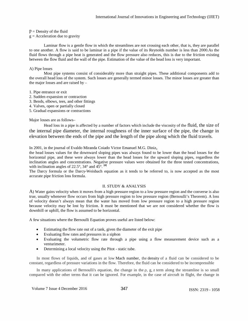
A) Spinning ball- The stitches on the ball will cause pressure on one side to be less than on its opposite side. This will force the ball to move faster on one side than the other and will force the ball to "curve." This is the Magnus Effect. When a pitcher throws a curveball, he will throw it such that the axis of rotation is not perpendicular to the ground, as it is in a fastball. Because it is spinning in a skewed axis, the Magnus force will force the ball to curve in a horizontal direction instead of vertical "curve" of a fastball.[3]
International Journal of Innovations in Engineering and Technology (IJIET)
351
Volume 7 Issue 4 December 2016 ISSN: 2319 - 1058
Figure. 4 Spinning of ball [6]
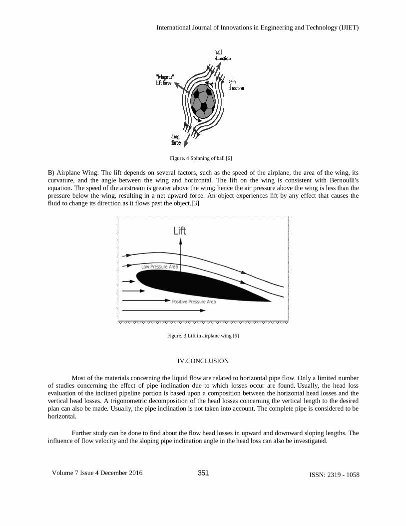
B) Airplane Wing: The lift depends on several factors, such as the speed of the airplane, the area of the wing, its curvature, and the angle between the wing and horizontal. The lift on the wing is consistent with Bernoulli's equation. The speed of the airstream is greater above the wing; hence the air pressure above the wing is less than the pressure below the wing, resulting in a net upward force. An object experiences lift by any effect that causes the fluid to change its direction as it flows past the object.[3]
Figure. 3 Lift in airplane wing [6]
IV.CONCLUSION
Most of the materials concerning the liquid flow are related to horizontal pipe flow. Only a limited number of studies concerning the effect of pipe inclination due to which losses occur are found. Usually, the head loss evaluation of the inclined pipeline portion is based upon a composition between the horizontal head losses and the vertical head losses. A trigonometric decomposition of the head losses concerning the vertical length to the desired plan can also be made. Usually, the pipe inclination is not taken into account. The complete pipe is considered to be horizontal.
Further study can be done to find about the flow head losses in upward and downward sloping lengths. The influence of flow velocity and the sloping pipe inclination angle in the head loss can also be investigated.
International Journal of Innovations in Engineering and Technology (IJIET)
352
Volume 7 Issue 4 December 2016 ISSN: 2319 - 1058
REFERENCES [1] Engineering Bernoulli Equation, R. Shankar Subramanian, Department of Chemical and Biomolecular
Engineering, Clarkson University.( pp.12 & 18) [2] Analyses and Modeling of Laminar Flow in Pipes Using Numerical Approach, O. Saheed Ismail, George T.
Adewoye, Department of Mechanical Engineering, University of Ibadan, Ibadan, Nigeria ( pp.1,2 & 5) [3] Bernoulli’s Principle – "Physics for Scientists and Engineers”, Fourth Edition, Vol.1, Raymond A. Serway,
Saunders College Publishing ( pp.1-2) [4] Two-Phase (Solid-Liquid) Flow in Inclined Pipes, Journal of the Brazilian Society of
MechanicalSciences,Print version ISSN 0100-7386, J. Braz. Soc. Mech.Sci. vol.23 no.3 Rio de Janeiro 2001( pp.1-3 , 9 -10 )
[5] www.ivorbittle.co.uk/Books/Fluids/ Chapter 7 The use of moody.htm