Fluids Buoyancy Fluid Dynamics Bernoulli's...
42
Fluids, Thermodynamics, Waves, and Optics Fluids Lana Sheridan De Anza College April 10, 2018
Transcript of Fluids Buoyancy Fluid Dynamics Bernoulli's...

Fluids, Thermodynamics, Waves, andOpticsFluids
Lana Sheridan
De Anza College
April 10, 2018

Overview
• static fluids
• pressure
• liquid pressure
• Pascal’s law

Elastic Properties of Solids
We are considering 3 kinds of elastic modulus in terms of:
Stress
the external force acting on an object per unit cross-sectional area
F/A
Strain
the fractional amount of change in shape of the object or material
For each:
elastic modulus =stressstrain
1See Serway & Jewett, Chapter 12 section 4.

Shear Modulus: Shape ElasticityShear modulus, S , is a measure of the resistance to motion ofparallel layers within a solid.
Y =F/A
∆x/h
where• F/A is the shear stress: F is a tangential force, parallel to
the surface F os applied to.• ∆x/h is the shear strain: ∆x is the distance the face is
displaced and h is the perpendicular distance between faces.
374 Chapter 12 Static Equilibrium and Elasticity
applying a sufficiently large stress as seen in Figure 12.12. Initially, a stress-versus-strain curve is a straight line. As the stress increases, however, the curve is no longer a straight line. When the stress exceeds the elastic limit, the object is permanently distorted and does not return to its original shape after the stress is removed. As the stress is increased even further, the material ultimately breaks.
Shear Modulus: Elasticity of ShapeAnother type of deformation occurs when an object is subjected to a force paral-lel to one of its faces while the opposite face is held fixed by another force (Fig. 12.13a). The stress in this case is called a shear stress. If the object is originally a rectangular block, a shear stress results in a shape whose cross section is a paral-lelogram. A book pushed sideways as shown in Figure 12.13b is an example of an object subjected to a shear stress. To a first approximation (for small distortions), no change in volume occurs with this deformation. We define the shear stress as F/A, the ratio of the tangential force to the area A of the face being sheared. The shear strain is defined as the ratio Dx/h, where Dx is the horizontal distance that the sheared face moves and h is the height of the object. In terms of these quantities, the shear modulus is
S ;shear stressshear strain
5F/A
Dx/h (12.7)
Values of the shear modulus for some representative materials are given in Table 12.1. Like Young’s modulus, the unit of shear modulus is the ratio of that for force to that for area.
Bulk Modulus: Volume ElasticityBulk modulus characterizes the response of an object to changes in a force of uni-form magnitude applied perpendicularly over the entire surface of the object as shown in Figure 12.14. (We assume here the object is made of a single substance.)
Shear modulus X
Table 12.1 Typical Values for Elastic Moduli Young’s Modulus Shear Modulus Bulk ModulusSubstance (N/m2) (N/m2) (N/m2)
Tungsten 35 3 1010 14 3 1010 20 3 1010
Steel 20 3 1010 8.4 3 1010 6 3 1010
Copper 11 3 1010 4.2 3 1010 14 3 1010
Brass 9.1 3 1010 3.5 3 1010 6.1 3 1010
Aluminum 7.0 3 1010 2.5 3 1010 7.0 3 1010
Glass 6.5–7.8 3 1010 2.6–3.2 3 1010 5.0–5.5 3 1010
Quartz 5.6 3 1010 2.6 3 1010 2.7 3 1010
Water — — 0.21 3 1010
Mercury — — 2.8 3 1010
Elasticlimit Breaking
point
Elasticbehavior
0.002 0.004 0.006 0.008 0.010
100
200
300
400
Stress(MPa)
Strain
Figure 12.12 Stress-versus-strain curve for an elastic solid.
The shearstress causesthe top faceof the blockto move tothe right relative tothe bottom.
–
!xA
Fixedface
h
FS
FS
a
FS
fsS
The shearstress causesthe frontcover of the book to move to the right relative to the back cover.
b
Physics
fsS
Figure 12.13 (a) A shear defor-mation in which a rectangular block is distorted by two forces of equal magnitude but opposite directions applied to two parallel faces. (b) A book is under shear stress when a hand placed on the cover applies a horizontal force away from the spine.

Fluids
Before looking at the third kind of elastic modulus, we willintroduce fluids.
The previous two elastic moduli apply to solids.
The bulk modulus is relevant for both solids and fluids.

FluidsThe term fluid encompasses both liquids and gases.
It is a collection of molecules that are only weakly influenced byintermolecular forces and thus can flow over each other.
Formally,
Fluids
deform continuously under shearing stress; have a shear modulus ofzero.
1Figure from Wikipedia, user Duk.

Fluid Statics
We first consider fluid statics: fluids at rest in a container.
Fish congregate around a reef in Hawaii searching for food. How do fish such as the lined butterflyfish (Chaetodon lineolatus) at the upper left control their movements up and down in the water? We’ll find out in this chapter. (Vlad61/Shutterstock.com)
14.1 Pressure
14.2 Variation of Pressure with Depth
14.3 Pressure Measurements
14.4 Buoyant Forces and Archimedes’s Principle
14.5 Fluid Dynamics
14.6 Bernoulli’s Equation
14.7 Other Applications of Fluid Dynamics
C H A P T E R
14Fluid Mechanics
417
Matter is normally classified as being in one of three states: solid, liquid, or gas. From everyday experience we know that a solid has a definite volume and shape, a liquid has a definite volume but no definite shape, and an unconfined gas has neither a definite volume nor a definite shape. These descriptions help us picture the states of matter, but they are somewhat artificial. For example, asphalt and plastics are normally considered solids, but over long time intervals they tend to flow like liquids. Likewise, most substances can be a solid, a liquid, or a gas (or a combination of any of these three), depending on the tempera-ture and pressure. In general, the time interval required for a particular substance to change its shape in response to an external force determines whether we treat the substance as a solid, a liquid, or a gas. A fluid is a collection of molecules that are randomly arranged and held together by weak cohesive forces and by forces exerted by the walls of a container. Both liquids and gases are fluids. In our treatment of the mechanics of fluids, we’ll be applying principles and analysis models that we have already discussed. First, we consider the mechanics of a fluid at rest, that is, fluid statics, and then study fluids in motion, that is, fluid dynamics.
14.1 PressureFluids do not sustain shearing stresses or tensile stresses such as those discussed in Chapter 12; therefore, the only stress that can be exerted on an object submerged in a static fluid is one that tends to compress the object from all sides. In other words, the force exerted by a static fluid on an object is always perpendicular to the surfaces of the object as shown in Figure 14.1. We discussed this situation in Section 12.4.
At any point on the surface of the object, the force exerted by the fluid is perpendicular to the surface of the object.
Figure 14.1 The forces exerted by a fluid on the surfaces of a sub-merged object.
Fluids will exert pressure on objects submerged in them and alsoon the walls of the container.

Pressure
Fish congregate around a reef in Hawaii searching for food. How do fish such as the lined butterflyfish (Chaetodon lineolatus) at the upper left control their movements up and down in the water? We’ll find out in this chapter. (Vlad61/Shutterstock.com)
14.1 Pressure
14.2 Variation of Pressure with Depth
14.3 Pressure Measurements
14.4 Buoyant Forces and Archimedes’s Principle
14.5 Fluid Dynamics
14.6 Bernoulli’s Equation
14.7 Other Applications of Fluid Dynamics
C H A P T E R
14Fluid Mechanics
417
Matter is normally classified as being in one of three states: solid, liquid, or gas. From everyday experience we know that a solid has a definite volume and shape, a liquid has a definite volume but no definite shape, and an unconfined gas has neither a definite volume nor a definite shape. These descriptions help us picture the states of matter, but they are somewhat artificial. For example, asphalt and plastics are normally considered solids, but over long time intervals they tend to flow like liquids. Likewise, most substances can be a solid, a liquid, or a gas (or a combination of any of these three), depending on the tempera-ture and pressure. In general, the time interval required for a particular substance to change its shape in response to an external force determines whether we treat the substance as a solid, a liquid, or a gas. A fluid is a collection of molecules that are randomly arranged and held together by weak cohesive forces and by forces exerted by the walls of a container. Both liquids and gases are fluids. In our treatment of the mechanics of fluids, we’ll be applying principles and analysis models that we have already discussed. First, we consider the mechanics of a fluid at rest, that is, fluid statics, and then study fluids in motion, that is, fluid dynamics.
14.1 PressureFluids do not sustain shearing stresses or tensile stresses such as those discussed in Chapter 12; therefore, the only stress that can be exerted on an object submerged in a static fluid is one that tends to compress the object from all sides. In other words, the force exerted by a static fluid on an object is always perpendicular to the surfaces of the object as shown in Figure 14.1. We discussed this situation in Section 12.4.
At any point on the surface of the object, the force exerted by the fluid is perpendicular to the surface of the object.
Figure 14.1 The forces exerted by a fluid on the surfaces of a sub-merged object.
Pressure
is the normal force per unit area on a surface:
P =F
A

Pressure
It is possible that the pressure on a surface varies over the surface.Then we will need to extend our definition:
δF = P δA
δF is the force on a tiny area δA.
As δA→ 0, the pressure can be a continuous function of theposition on the surface.
Units: the Pascal (after Blaise Pascal), symbol Pa1 Pa = 1 N/m2

PressurePressure is a scalar quantity.
We relate it to force, a vector, by:
δF = P δA n
where n is a unit vector perpendicular to the small area δA.
In a gas or liquid, its underlying cause is molecular collisions:
1Diagram by Brant Carlson, on Wikipedia.

Question
Quick Quiz 14.11 Suppose you are standing directly behindsomeone who steps back and accidentally stomps on your foot withthe heel of one shoe. Would you be better off if that person were
A a large, male professional basketball player wearing sneakers or
B a petite woman wearing spike-heeled shoes?
1Page 418, Serway & Jewett

Question
Quick Quiz 14.11 Suppose you are standing directly behindsomeone who steps back and accidentally stomps on your foot withthe heel of one shoe. Would you be better off if that person were
A a large, male professional basketball player wearing sneakers or↑
B a petite woman wearing spike-heeled shoes?
1Page 418, Serway & Jewett

Ambient Atmospheric Pressure
The air around us exerts force on us, the walls of the room, thefloor, etc.
Is it a large pressure?
In a sense, yes!
P0 = Patm = 1.013× 10⁵ Pa

Ambient Atmospheric Pressure
The air around us exerts force on us, the walls of the room, thefloor, etc.
Is it a large pressure?
In a sense, yes!
P0 = Patm = 1.013× 10⁵ Pa

Bulk Modulus: Volume ElasticityBulk modulus, S , is a measure of the resistance to compression ofa material.
B = −∆P
∆V /Vi
The negative sign ensures B will be a positive number.
12.4 Elastic Properties of Solids 375
As we shall see in Chapter 14, such a uniform distribution of forces occurs when an object is immersed in a fluid. An object subject to this type of deformation undergoes a change in volume but no change in shape. The volume stress is defined as the ratio of the magnitude of the total force F exerted on a surface to the area A of the sur-face. The quantity P 5 F/A is called pressure, which we shall study in more detail in Chapter 14. If the pressure on an object changes by an amount DP 5 DF/A, the object experiences a volume change DV. The volume strain is equal to the change in volume DV divided by the initial volume Vi. Therefore, from Equation 12.5, we can character-ize a volume (“bulk”) compression in terms of the bulk modulus, which is defined as
B ;volume stressvolume strain
5 2DF/ADV/Vi
5 2DP
DV/Vi (12.8)
A negative sign is inserted in this defining equation so that B is a positive number. This maneuver is necessary because an increase in pressure (positive DP) causes a decrease in volume (negative DV) and vice versa. Table 12.1 lists bulk moduli for some materials. If you look up such values in a different source, you may find the reciprocal of the bulk modulus listed. The recip-rocal of the bulk modulus is called the compressibility of the material. Notice from Table 12.1 that both solids and liquids have a bulk modulus. No shear modulus and no Young’s modulus are given for liquids, however, because a liquid does not sustain a shearing stress or a tensile stress. If a shearing force or a tensile force is applied to a liquid, the liquid simply flows in response.
Q uick Quiz 12.4 For the three parts of this Quick Quiz, choose from the fol-lowing choices the correct answer for the elastic modulus that describes the relationship between stress and strain for the system of interest, which is in ital-ics: (a) Young’s modulus (b) shear modulus (c) bulk modulus (d) none of those choices (i) A block of iron is sliding across a horizontal floor. The friction force between the sliding block and the floor causes the block to deform. (ii) A tra-peze artist swings through a circular arc. At the bottom of the swing, the wires supporting the trapeze are longer than when the trapeze artist simply hangs from the trapeze due to the increased tension in them. (iii) A spacecraft carries a steel sphere to a planet on which atmospheric pressure is much higher than on the Earth. The higher pressure causes the radius of the sphere to decrease.
Prestressed ConcreteIf the stress on a solid object exceeds a certain value, the object fractures. The max-imum stress that can be applied before fracture occurs—called the tensile strength, compressive strength, or shear strength—depends on the nature of the material and on the type of applied stress. For example, concrete has a tensile strength of about 2 3 106 N/m2, a compressive strength of 20 3 106 N/m2, and a shear strength of 2 3 106 N/m2. If the applied stress exceeds these values, the concrete fractures. It is common practice to use large safety factors to prevent failure in concrete structures. Concrete is normally very brittle when it is cast in thin sections. Therefore, concrete slabs tend to sag and crack at unsupported areas as shown in Figure 12.15a. The slab can be strengthened by the use of steel rods to reinforce the concrete as illustrated in Figure 12.15b. Because concrete is much stronger under compression (squeezing) than under tension (stretching) or shear, vertical columns of concrete can support
�W Bulk modulus
Figure 12.14 A cube is under uniform pressure and is therefore compressed on all sides by forces normal to its six faces. The arrow-heads of force vectors on the sides of the cube that are not visible are hidden by the cube.
Vi
Vi ! "V
FtopS
FbackS
FrightS
FbottomS
FfrontS
FleftS
The cube undergoes a change in volume but no change in shape.
a b c
Concrete CracksLoad force Steel
reinforcingrod
Steel rodunder
tension
Figure 12.15 (a) A concrete slab with no reinforcement tends to crack under a heavy load. (b) The strength of the concrete is increased by using steel reinforce-ment rods. (c) The concrete is fur-ther strengthened by prestressing it with steel rods under tension.
where
• ∆F/A is the volume stress orpressure change.
• ∆V /Vi is the volume strain:∆V is the change from theinitial volume Vi .
The reciprocal of the bulk modulus,1/B, is the compressibility of thematerial.

Pressure in a Liquid in a Gravitational Field
In a uniform gravitational field, liquid pressure depends on depth.
Pliq = ρgh
where ρ = m/V is the mass density of the liquid and h is thedepth.
It does not depend on the total amount of water involved, just thedepth of water.

Liquid PressureA slice of liquid of cross section A at a depth h must support allthe water in a column directly above it.
The force exerted downward by the column of water isF = mg = ρVg .

Liquid Pressure
F = mg = ρVg = ρAhg
Pressure, Pliq = FA = ρAhg
A = ρgh.
1Figure from HyperPhysics.

Liquid Pressure
F = mg = ρVg = ρAhg
Pressure, Pliq = FA = ρAhg
A = ρgh.
1Figure from HyperPhysics.

Total Pressure
The liquid pressure only expresses the pressure due to the weight ofthe fluid above.
However, this is not the total pressure in most circumstances,eg. diving on earth.
The total pressure or absolute pressure is the sum of the pressuredue to the liquid and the pressure due to the atmosphere.
Ptotal = P0 + ρgh
where P0 = Patm = 1.013× 10⁵ Pa.

Pressure varies with Depth
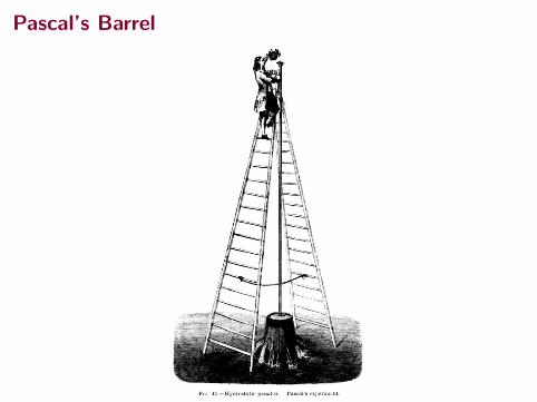
Pascal’s Barrel
1Illustration from ‘The forces of nature’ by Amedee Guillemin, 1872.

Density of Water
For water:ρw = 1.00× 10³ kg/m3
That is ρw = 1 g/cm3.
Originally, the gram was defined to be the mass of one cubiccentimeter of water at the melting point of water.

Density of Water
For water:ρw = 1.00× 10³ kg/m3
That is ρw = 1 g/cm3.
Originally, the gram was defined to be the mass of one cubiccentimeter of water at the melting point of water.

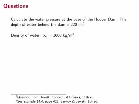
Questions
Calculate the water pressure at the base of the Hoover Dam. Thedepth of water behind the dam is 220 m.2
Density of water: ρw = 1000 kg/m3
Pliq = 2.16× 10⁶ Pa
Ptotal ≈ 2.3× 10⁶ Pa
Now consider, if the dam is 380 m long, what is the total forceexerted by the water on the dam?3
2Question from Hewitt, Conceptual Physics, 11th ed.3See example 14.4, page 422, Serway & Jewett, 9th ed.

QuestionsNow consider, if the dam is 380 m long, what is the total forceexerted by the water on the dam?
422 Chapter 14 Fluid Mechanics
eardrum from the depth given in the problem; then, after estimating the ear drum’s surface area, we can determine the net force the water exerts on it.
Categorize This example is a substitution problem.The air inside the middle ear is normally at atmospheric pressure P0. Therefore, to find the net force on the eardrum, we must consider the difference between the total pressure at the bottom of the pool and atmospheric pressure. Let’s estimate the surface area of the eardrum to be approximately 1 cm2 5 1 3 1024 m2.
Use Equation 14.4 to find this pressure difference:
Pbot 2 P0 5 rgh
5 (1.00 3 103 kg/m3)(9.80 m/s2)(5.0 m) 5 4.9 3 104 Pa
Use Equation 14.1 to find the magnitude of the net force on the ear:
F 5 (Pbot 2 P0)A 5 (4.9 3 104 Pa)(1 3 1024 m2) < 5 N
Because a force of this magnitude on the eardrum is extremely uncomfortable, swimmers often “pop their ears” while under water, an action that pushes air from the lungs into the middle ear. Using this technique equalizes the pressure on the two sides of the eardrum and relieves the discomfort.
Example 14.4 The Force on a Dam
Water is filled to a height H behind a dam of width w (Fig. 14.5). Determine the resultant force exerted by the water on the dam.
Conceptualize Because pressure varies with depth, we cannot calculate the force simply by multiplying the area by the pressure. As the pressure in the water increases with depth, the force on the adjacent portion of the dam also increases.
Categorize Because of the variation of pressure with depth, we must use integra-tion to solve this example, so we categorize it as an analysis problem.
Analyze Let’s imagine a vertical y axis, with y 5 0 at the bottom of the dam. We divide the face of the dam into narrow horizontal strips at a distance y above the bottom, such as the red strip in Figure 14.5. The pressure on each such strip is due only to the water; atmospheric pressure acts on both sides of the dam.
S O L U T I O N
O
dy
y
h
w
H
y
x
Figure 14.5 (Example 14.4) Water exerts a force on a dam.
Use Equation 14.4 to calculate the pressure due to the water at the depth h :
P 5 rgh 5 rg(H 2 y)
Use Equation 14.2 to find the force exerted on the shaded strip of area dA 5 w dy :
dF 5 P dA 5 rg(H 2 y)w dy
Integrate to find the total force on the dam: F 5 3P dA 5 3H
0rg 1H 2 y 2w dy 5 1
2rgwH 2
Finalize Notice that the thickness of the dam shown in Figure 14.5 increases with depth. This design accounts for the greater force the water exerts on the dam at greater depths.
What if you were asked to find this force without using calculus? How could you determine its value?
Answer We know from Equation 14.4 that pressure varies linearly with depth. Therefore, the average pressure due to the water over the face of the dam is the average of the pressure at the top and the pressure at the bottom:
Pavg 5Ptop 1 Pbottom
25
0 1 rgH2
5 12rgH
WHAT IF ?
▸ 14.3 c o n t i n u e d
3See example 14.4, page 422, Serway & Jewett, 9th ed.
F = 9.0×10¹⁰ N

Pressure in a liquid
We have this expression for total pressure:
Ptotal = P0 + ρgh
What if the pressure at the surface of the liquid, P0, was increasedto P1.
How would we expect this relation to change?
Ptotal = P1 + ρgh
The differences in pressure between the different layers of liquidremain the same, but the pressure at each depth h increases.

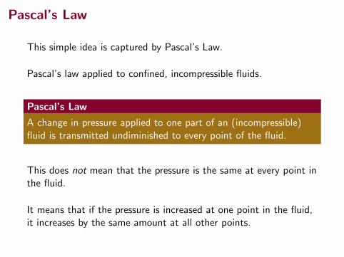
Pascal’s Law
This simple idea is captured by Pascal’s Law.
Pascal’s law applied to confined, incompressible fluids.
Pascal’s Law
A change in pressure applied to one part of an (incompressible)fluid is transmitted undiminished to every point of the fluid.
This does not mean that the pressure is the same at every point inthe fluid.
It means that if the pressure is increased at one point in the fluid,it increases by the same amount at all other points.
Pascal’s Law
This simple idea is captured by Pascal’s Law.
Pascal’s law applied to confined, incompressible fluids.
Pascal’s Law
A change in pressure applied to one part of an (incompressible)fluid is transmitted undiminished to every point of the fluid.
This does not mean that the pressure is the same at every point inthe fluid.
It means that if the pressure is increased at one point in the fluid,it increases by the same amount at all other points.

Pascal’s Principle
Since the changes in pressures at the left end and the right end arethe same:
∆P1 = ∆P2
F1A1
=F2A2
Since A2 > A1, F2 > F1.
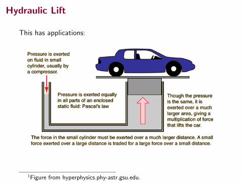
Hydraulic Lift
This has applications:
1Figure from hyperphysics.phy-astr.gsu.edu.

Question
If a pair of pistons are connected on either end of a hydraulic tube.The first has area 0.2 m2 and the second has an area of 4 m2.
A force of 30 N is applied the first piston. What is the forceexerted by the second piston on a mass that rests on it?
If the first piston is depressed a distance of 1 m by the 30 N force,how far does the second piston rise?

Summary
• static fluids
• pressure
• Pascal’s law
Test Tuesday, April 17, in class.
Collected Homework due Monday, April 16.
(Uncollected) Homework• Ch 12, onward from page 382, Obj Ques: 9; Probs: 27, 29.
• Ch 14, onward from page 435, OQs: 1; CQs: 1, 3, 7; Probs:1, 3, 7, 8, 9, 11, 15, 18