A-Series Dental Unit Cover
11
Operator’s Instructions A-Series Dental Units Document 9050740 Rev C 02/10
Transcript of A-Series Dental Unit Cover

Operator’s Instructions
A-Series Dental Units
Document 9050740 Rev C 02/10

Operator’s Instructions
SpecificationsEnlighten B
Electrical Input:Voltage 120 VACPhase 1Frequency 50 / 60HzPower 15 VA
Electrical Output:Voltage 9 VACCurrent 1000 mAPower 9 W
Enlighten F
Electrical Input:Voltage 120 VACPhase 1Frequency 50 / 60HzPower 1A
Electrical Output:Voltage 13.7 - 12.2 VACCurrent 8.6 APower 104.92-117.82 W
Cavitron Ultrasonic Scaler
Electrical Input:Voltage 115 VACPhase 1Frequency 50 / 60HzPower 1.25 A
Electrical Output:Voltage 24 VACCurrent 1.25 APower 30 W
Pneumatic Specifications:
Water Pressure Patient Bottle........ 35 psi (241.4 Kpa) City Water............. 35 psi (241.4 Kpa)Air Pressure Regulated............. 80 psi (551.8 Kpa)
Operating ConditionsAmbientTemperature +10 C to +40 CHumidity 30% to 75%AtmosphericPressure Range 700 hPa to 1060 hPa
Storage & Shipping
AmbientTemperature - 40 C to +70 C Humidity 10 to 95 RH (non-condensing)AtmosphericPressure Range 7 to 15 psi (50 to 106 Kpa)
ClassificationsClassificationof Equipment Class I
Degree of Protec-tion against harmful ingress of water
Mode of Operation Intermittent
Ordinary
Technical SupportFor Technical support and repair assis-tance, contact your local Proma dealer
A-Series Dental Units
Operating Conditions.......................... 1
Storage & Shipping Conditions........... 1
Classifications..................................... 1
Technical Support................................1
Specifications...................................... 1
Replacement Parts..............................2
Care & Disinfecttion............................ 2
Warranty.............................................. 2
Control Locations Selector Head
w/Pinch Control Blocks....................... 3
w/Traditional Control Block................. 4
Control Locations A5410..................... 5
Flex Arm Counterbalance
Adjustment................. ......................... 6
Cuspidor Controls............................... 7
Assistant Vacuum Controls................. 8
Work Surface Height Adjustment........ 8
Dental Patient Water System.............. 9
Solids Collector................................. 10
Table of Content
730 E. Kingshill Place • Carson, CA 90746Phone 310.327.0035 • Fax 310.327.4601
Document 9050740 Rev C 02 /10

Warranty
Care & Disinfection
2
Replacement PartsTo order supplies or replacements parts for the A-Series dental unit, contact your local Proma dealer.
Part Number Description
50001052A Uni-Handpiece Holder Assembly, Right500010621 Uni-Handpiece Holder Assembly, Left8010410 Cooling Air Value Assembly8020110 Control Module Assembly, Selector Head8020140B Water Protect Valve Assembly41150004 Amalgam Trap Assembly4115006 Amalgam Trap Lid90989 O-Ring, Lid Amalgam Trap93013 HVE Valve Assembly93014 Saliva Ejector Assembly93015 Lever, HVE93018 Lever, Saliva Ejector5013170 Socket Pressure Assembly46188006 56 inch Handpiece Hose92751 Syringe Assembly92982 Gasket, Socket Pressure9128600K One Litter Water Bottle Kit9132700K Two Litter Water Bottle Kit20150022 Channel Tilt, Telescoping Arm8257002 Absorbing Oil Collector Pad8030107 ½ - 20 Finishing Nut91032 Stainless Steel Tray92451 Syringe Repair Kit92814 Foot Control Repair Kit91267 Diaphragm Pilot Valve91462 Air Regulator Repair Kit91463 Water Regulator Repair Kit91301 Pilot Valve Repair Kit
Use Disposable Plastic Films and FoilsProma encourages the use of disposable films and foils on handles and surfaces commonly touched with gloved hands. This can reduce the need for chemical surface disinfection and extend the life span and appearance of these surfaces.
Do Not Soak Plastic PartsThe useful life of many plastics may be greatly shortened by soaking in any disinfectant solution for unnecessarily long periods.
Cleaning Your Proma UnitClean and disinfect the unit at beginning and end of workday and week.
Proma only approves the use of a mild soap and water solu-tion, applied with a soft cloth.
Proma recommends Birex®SE manufactured by BiotrolInternational
The outside surfaces may be cleaned with a moist (not drip-ping) soft towel soaked in any mild soap and water solution and squeezed dry. Wipe and dry with a soft towel. Do not use abrasive cleaners or rough paper towel which may scratch the molded surfaces. After cleaning, wipe all surfaces with a gauze sponge moistened (not dripping) in a properly pre-pared diluted disinfectant.
Unitized Handpiece Holders
Proma also recommends the use of “Soft Scrub ® with Bleach” to clean the handpiece cavity of the holder. Apply cleaner to a soft cloth and rub the area to be cleaned.
Proma warrants its products against defects in materials and / or workmanship for five years from the date of ship-ment from the factory. No other warranties are expressed or implied. No employee, representative or dealer is autho-rized to change this warranty in any way, or grant any other warranty dealing with this product. Proma’s sole obligation under this warranty is limited to repair, replace, or modify the defective part or product if, in its judgment, this is advis-able. Labor and other costs for removal and reinstallation are not included in this warranty. The buyer shall have no other remedy. (All special, incidental, and consequential damages are excluded.) Written notice of breach of warranty must be given to Proma within the warranty period. The warranty
does not cover damages resulting from improper installa-tion or maintenance, accident or misuse. Warranty is void if product is not installed by an authorized Proma dealer. NO OTHER WARRANTIES AS TO MERCHANTABILITY, FIT-NESS FOR USE OR OTHERWISE ARE MADE. This war-ranty gives specific legal right, and there may also be other rights which vary from state to state. (Some states do not al-low the exclusion or limitation of incidental or consequential damages, so the above exclusion may not apply.)
Proma will provide service advice and instructions as re-quired for repair or replacement of this product.Call 1.310.327.0035 for service.

1
2
3
4
5
6
8
9
10
7
1
2
3
4
5 67
8
10
9
3
Control Locations, Selector Head with Pinch Control Block
Master Air & Water ON / Off Toggle Opens and closes the air and water supply forthe complete system. Exhausts air when turned off Important: Shut off system by setting toggle to the off position each night before removingPatient Water bottle, or when not in use
Handpiece Coolant Water On/Off ToggleOn / Off for handpiece water. Turn off for low-speeds that normally do not require watercoolant.
Handpiece Water Flush SystemFlushes handpieces with water. Remove handpiece from selector and hold over basin or cuspidor bowl. Open fine mist controls fully.Pull forward for two minutes before first patient. Ten seconds between patients. Adjust fine mist controls.
Arm Lock/Release Momentary Valve
Releases vertical arm travel lock. Push-in but-ton to unlock arm and release button to lock. Exhausts air when released
Handpiece Pressure Gauge
Avoid exceeding manufacturer’s recommened air pressure – 30 to 35 psi for most high-speed handpieces.
Drive Air Pressure Control Knob (Yellow )
Adjusts drive air pressure to the handpiece. Clockwise decreases pressure, Counter-clockwise increases pressureCaution: Excess pressure damages handpiece bearings
Coolant Water Fine Mist Control Knob (Blue)
Control water coolant to handpieces. Counter-clockwise increases pressure and clockwisedecreases pressure.
Coarse Water ControlStops water dripping after foot control is re leased. Adjust to fine mist with fine mist con-trols full opened
Oil Collection JarPad absorbs handpiece oil. Unscrew and empty jar and replace pad weekly. Order kit 912-81-00 (24 pads)
Coolant Air Adjustment Control KnobAdjusts coolant airflow to all handpieces. Counter-clockwise increases pressure and Clockwise decreases pressure.

1
2
3
4
5
6
7
8
9
10
1
2
3
6
5
6
7
9
10
48
4
Control Locations, Selector Head with Traditional Control Block
Oil Collection JarPad absorbs handpiece oil. Unscrew and empty jar and replace pad weekly. Order kit 912-81-00 (24 pads)
Coolant Air Adjustment Control KnobAdjusts coolant airflow to all handpieces. Counter-clockwise increases pressure and Clockwise decreases pressure.
Master Air & Water ON / Off Toggle Opens and closes the air and water supply forthe complete system. Exhausts air when turned off Important: Shut off system by setting toggle to the off position each night before removingPatient Water bottle, or when not in use
Handpiece Coolant Water On/Off ToggleOn / Off for handpiece water. Turn off for low-speeds that normally do not require watercoolant.
Handpiece Water Flush SystemFlushes handpieces with water. Remove handpiece from selector and hold over basin or cuspidor bowl. Open fine mist controls fully.Pull forward for two minutes before first patient. Ten seconds between patients. Adjust fine mist controls.
Arm Lock/Release Momentary Valve
Releases vertical arm travel lock. Push-in but-ton to unlock arm and release button to lock. Exhausts air when released
Handpiece Pressure Gauge
Avoid exceeding manufacturer’s recommened air pressure – 30 to 35 psi for most high-speed handpieces.
Drive Air Pressure Control Knob
Adjusts drive air pressure to the handpiece. Clockwise decreases pressure, Counter-clockwise increases pressureCaution: Excess pressure damages handpiece bearings
Coolant Water Fine Mist Control Knob (Blue)
Control water coolant to handpieces. Counter-clockwise increases pressure and clockwisedecreases pressure.
Coarse Water ControlStops water dripping after foot control is re leased. Adjust to fine mist with fine mist con-trols full opened

1
2
3
4
5
6
7
8
9
10
1
2
3
8
4
7
6 5
8
10 9
5
Control Locations, Selector Head with Pinch Valve Control
Oil Collection JarPad absorbs handpiece oil. Unscrew and empty jar and replace pad weekly. Order kit 912-81-00 (24 pads)
Coolant Air Adjustment Control KnobAdjusts coolant airflow to all handpieces. Counter-clockwise increases pressure and Clockwise decreases pressure.
Master Air & Water ON / Off Toggle Opens and closes the air and water supply forthe complete system. Exhausts air when turned off Important: Shut off system by setting toggle to the off position each night before removingPatient Water bottle, or when not in use
Handpiece Coolant Water On/Off ToggleOn / Off for handpiece water. Turn off for low-speeds that normally do not require watercoolant.
Handpiece Water Flush SystemFlushes handpieces with water. Remove handpiece from selector and hold over basin or cuspidor bowl. Open fine mist controls fully.Pull forward for two minutes before first patient. Ten seconds between patients. Adjust fine mist controls.
Handpiece Pressure Gauge
Avoid exceeding manufacturer’s recommened air pressure – 30 to 35 psi for most high-speed handpieces.
Drive Air Pressure Control Knob (Yellow)
Adjusts drive air pressure to the handpiece. Clockwise decreases pressure, Counter-clockwise increases pressureCaution: Excess pressure damages handpiece bearings
Coolant Water Fine Mist Control Knob (Blue)
Control water coolant to handpieces. Counter-clockwise increases pressure and clockwisedecreases pressure.
Coarse Water ControlStops water dripping after foot control is re leased. Adjust to fine mist with fine mist con-trols full opened
Solids Collector
Catches debris that would otherwise clog sub-floor vacuum pumps and plumbing. Remove and replaceable screen (Proma part #91475). Treat as biocontaminated waste* (see caution on page 00). Always flush vacuum system be-fore changing screen.
WaterBottle

1
1
2
3
4
23
4
6
Flex Arm Counterbalanced AdjustmentThe flex arm counterbalanced spring tension is factory adjusted carry the weight of the unit plus an additional 1½ pounds. If the user’s application requires the flex arm to carry an additional load, the counterbalanced spring can be adjusted to carry up to, but not exceeding 10 additional pounds.
Warning
Do not over tighten the flex arm counterbalanced spring. The flex arm counterbalance mechanism is designed to compensate for a maximum of 10 pounds of additional load. Adjusting the spring tension to carry more than an additional 10 pounds may cause permanent damage to the flex arm.
OTP Flex Arm Shown
Counterbalance Spring
Gear Nut
¼” Slot in Undersideof Flex Arm Support
Bottom Cover
Full Stroke
Tighten
Loosen
Gear Nut
Adjusting the Flex Arm Counterbalance Spring Tension
Remove the plastic bottom cover by pulling down on one end. Insert a flathead screwdriver thru the ¼” slot in the underside of the flex arm support and rotate the gear nut that compresses the counterbalance spring. See figure left.
Dual Cabinet / Wall Mount Unit
One full stroke of screwdriver will increase/decrease the flex arm counterbalance by 1/10th (.10) pounds
OTP, Doctor and Hygiene Cabinet Units
One full stroke of screwdriver will increase/decrease the flex arm counterbalance by 1/16” (.06) pounds
7
A
B
C
D
E
F
A
A
A
BC E
D F
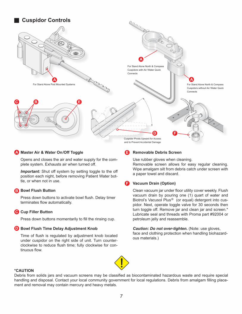
Cuspidor Controls
*CAUTIONDebris from solids jars and vacuum screens may be classified as biocontaminated hazardous waste and require special handling and disposal. Contact your local community government for local regulations. Debris from amalgam filling place-ment and removal may contain mercury and heavy metals.
Cuspidor Pivots Upward for Accessand to Prevent Accidental Damage
Master Air & Water On /Off Toggle
Opens and closes the air and water supply for the com-plete system. Exhausts air when turned off.
Important: Shut off system by setting toggle to the off position each night, before removing Patient Water bot-tle, or when not in use.
Bowl Flush Button
Press down buttons to activate bowl flush. Delay timer terminates flow automatically.
Cup Filler Button
Press down buttons momentarily to fill the rinsing cup.
Bowl Flush Time Delay Adjustment Knob
Time of flush is regulated by adjustment knob located under cuspidor on the right side of unit. Turn counter-clockwise to reduce flush time; fully clockwise for con-tinuous flow.
Removable Debris Screen
Use rubber gloves when cleaning.Removable screen allows for easy regular cleaning. Wipe amalgam silt from debris catch under screen with a paper towel and discard.
Vacuum Drain (Option)
Clean vacuum jar under floor utility cover weekly. Flush vacuum drain by pouring one (1) quart of water and Biotrol’s Vacusol Plus ® (or equal) detergent into cus-pidor. Next, operate toggle valve for 30 seconds then turn toggle off. Remove jar and clean jar and screen.* Lubricate seal and threads with Proma part #92004 or petroleum jelly and reassemble.
Caution: Do not over-tighten. (Note: use gloves, face and clothing protection when handling biohazard-ous materials.)
For Stand Alone Post Mounted Systems
For Stand Alone North & Compass Cuspidors with Air / Water Quick Connects
For Stand Alone North & Compass Cuspidors without Air / Water Quick Connects

1
1
2 3 4
23
4
1 2
3 4
Assistant Vacuum Controls
8
ProValve Plus HVEOne autoclavable ProValve Plus is provide on most Proma vacuum packages. Variable control of the wet central vacuum system is obtained by adjusting the lever on the valve. See de-tails below for cleaning and sterilization procedure.
Saliva Ejector Valve(Low volume vacuum) Autoclavable. A debris screen is provided under the tip. For trouble-free service, clean thoroughly by flushing daily with water. Use a non-foaming flushing detergent weekly.An occasional spray of a handpiece lubricant will keep the knobs free of excess debris. Clean or replace Saliva Ejector screen after each patient with Proma part # 91057 or equal. Handle screen as biocontaminated waste*
Sterilization of ProValve Plus and Saliva Ejector Valves
• Disconnect valve from swivel• Spread lever tips outward slightly and remove from spool. (Note By reversing spool end, you will reverse level on and off position).• Push spool outward• Clean thoroughly all O-rings, valve body and spool parts inside and out with diluted germicidal detergent. Rinse thoroughly and dry.• Lubricate O-rings and all moving parts using Proma silicone lubricant (part # 92004).
• Reassemble valve and sterilize.
Dual Cart & 12 O’Clock Cabinet Mount UnitWork Surface Height Adjustment
Always remove heavy loads from work surface.Locate Height Adjust knob and with one hand supporting the work surface, loosen the knob.Raise or lower work surface to desired heightSecurely tighten knob
Height AdjustmentKnob (A5630)
Height AdjustmentKnob (A5550)
Valve Body Spool Lever Swivel

CautionStudies show most improperly maintained dental unit water lines have microbial contamination. For proper use and maintenance, please read and follow instructions. Failure to perform this mainte-nance can promote contamination.
Dental Patient Water System
9
Dental Patient Water Systems: The Choices
Users can control water quality and contaminates by properly using Proma’s Dental Patient Water System. This system consists of an isolated bottle and all polymer pathways through the selector and allows for regular treatment with bleach solution to address effects of contamination.
The bottle holds sufficient water for a normal day’s use. Heavy users may require mid-day refill. A bottle simply unscrews for refilling. Use only Proma bottles on Proma water system.
Use only distilled or demineralized water and treat empty bottles with a rinse of bleach solution once weekly.
Water System Maintenance
Control asepsis by filling from a quality water source and using proper water handling and filling techniques.
Follow instructions in Quick Notes, document 9050261, to reduce the risk of contamination in your water lines.
Post Enclosure Mount
A5630 Dual Cart A5610 Doctor Cart
A5550 Dual Cabinet Mount
Stand AloneSystem Mount
A5210 Compass Mount Unit with A5760 North Mount Vacuum

Catches debris that would otherwise clog sub floor vacuum pumps and plumbing. Removable and replaceable screen (Proma part # 91475). Treat as biocontaminated waste. * Always flush vacuum system before cleaning screen.
Solids Collector
Solids Collector
10
Cleaning of Vacuum System
• Open all valves to drain excess water and relieve pressure
• Leave valves open and flush hoses with warm water ad germicidal detergent (Vacusol or equal).
• Wearing rubber gloves, open Solids Collector and remove Screen (Note: wear gloves, face shield and protective clothing when handling biohazardous materials.)
• Empty debris into paper towel and properly dispose.*
• Thoroughly wash and wipe collector lid and screen, especially sealing edges.
• Apply silicone paste (Proma part # 92004) or petroleum jelly to lid and sealing edges.
• Reinstall screen, replace lid and close valves.
* CautionDebris from solids jar and vacuum screens may be clas-sified as biocontaminated hazardous waste and require special handling and disposal. Contact your local commu-nity government for regulations. Debris from amalgam filling placement and removal may contain mercury and heavy metals.
Chair Mounted Unit
Solids Collector
Dual 12 O’Clock Unit
Solids Collector
Air / Water Outlet Quick Connect
Air Outlet Quick Connect (Optional)
Water Outlet Quick Connect
Solids Collector
Solids CollectorSolids Collector
Air Outlet QuickConnect (Optional)
Water OutletQuick Connect
North Assistant Dual Cart & Assistant Cart Dual Cabinet Mount Unit


![001 1562R383R FRANÇAIS MODE D'EMPLOI [Unit Dose] I ... · 3. Light-cure BOND with a dental curing unit (see table “Dental curing unit and curing time”). Table: Dental curing](https://static.fdocuments.in/doc/165x107/5f7ba0f1a367dc37781f72b2/001-1562r383r-franais-mode-demploi-unit-dose-i-3-light-cure-bond-with.jpg)