A Semi-analytical Approach for Time-dependent Load-A Semi-analytical Approach for Time-dependent...
46
Draft A Semi-analytical Approach for Time-dependent Load- settlement Response of a Jacked Pile in Clay Strata Journal: Canadian Geotechnical Journal Manuscript ID cgj-2016-0561.R1 Manuscript Type: Article Date Submitted by the Author: 11-Apr-2017 Complete List of Authors: Li, Lin; Tongji University College of Civil Engineering, Department of Geotechnical Engineering Li, Jingpei; Tongji University College of Civil Engineering, Geotechnical Engineering; Sun, De'an; Shanghai University, Department of Civil Engineering Gong, Weibing; Tongji University College of Civil Engineering, Department of Geotechnical Engineering Keyword: jacked pile, time-dependent, bearing performance, load-transfer, nonlinear https://mc06.manuscriptcentral.com/cgj-pubs Canadian Geotechnical Journal
Transcript of A Semi-analytical Approach for Time-dependent Load-A Semi-analytical Approach for Time-dependent...

Draft
A Semi-analytical Approach for Time-dependent Load-
settlement Response of a Jacked Pile in Clay Strata
Journal: Canadian Geotechnical Journal
Manuscript ID cgj-2016-0561.R1
Manuscript Type: Article
Date Submitted by the Author: 11-Apr-2017
Complete List of Authors: Li, Lin; Tongji University College of Civil Engineering, Department of Geotechnical Engineering Li, Jingpei; Tongji University College of Civil Engineering, Geotechnical Engineering; Sun, De'an; Shanghai University, Department of Civil Engineering Gong, Weibing; Tongji University College of Civil Engineering, Department
of Geotechnical Engineering
Keyword: jacked pile, time-dependent, bearing performance, load-transfer, nonlinear
https://mc06.manuscriptcentral.com/cgj-pubs
Canadian Geotechnical Journal

Draft
1Ph.D. Student, Department of Geotechnical Engineering, Tongji Univ., Shanghai
200092, China. E-mail: [email protected]
2Professor, Department of Geotechnical Engineering, Tongji Univ., Shanghai 200092,
China (corresponding author). E-mail: [email protected]
3Professor, Department of Civil Engineering, Shanghai Univ., Shanghai 200444,
China. E-mail: [email protected]
4Master’s Degree Candidate, Department of Geotechnical Engineering, Tongji Univ.,
Shanghai 200092, China. E-mail: [email protected]
A Semi-analytical Approach for Time-dependent
Load-settlement Response of a Jacked Pile in Clay Strata
Lin Li1, Jingpei Li
2,*, De’an Sun
3, Weibing Gong
4
Page 1 of 45
https://mc06.manuscriptcentral.com/cgj-pubs
Canadian Geotechnical Journal

Draft
2
Abstract: The mechanical behaviour of the soil around a jacked pile changes
significantly during pile installation and subsequent consolidation. Hence an axially
loaded jacked pile exhibits apparently time-dependent bearing performance after pile
installation. This paper presents a semi-analytical approach to predict the
time-dependent bearing performance of an axially loaded jacked pile in saturated clay
strata. The effects of pile installation and subsequent consolidation on the changes in
mechanical properties of the surrounding soil are modeled by the cavity expansion
theory and the radial consolidation theory, respectively. An exponential function based
load-transfer (t-z) curve is employed to describe the nonlinear behaviour of the
pile-soil interface during pile loading. The evolutions of the three dimensional
strength and the shear modulus of the surrounding soil are subsequently incorporated
into the two model parameters of the proposed t-z curve to capture the time-dependent
pile-soil interaction behaviour. The time-dependent elastic response of the soil outside
the pile-soil interface is also considered in the proposed approach. With the proposed
load-transfer curve, an incremental algorithm and a corresponding computational code
are developed for assessing the time-dependent load-settlement response of a jacked
pile. To verify the proposed semi-analytical approach, predictions of the
time-dependent load-settlement curves are compared with the measured values from
pile tests at two sites. The good agreement shows that the time-dependent bearing
performance can be reasonably predicted by the proposed approach.
Key words: jacked pile, time-dependent, bearing performance, load-transfer, nonlinear,
pile-soil interaction
Page 2 of 45
https://mc06.manuscriptcentral.com/cgj-pubs
Canadian Geotechnical Journal
Draft
3
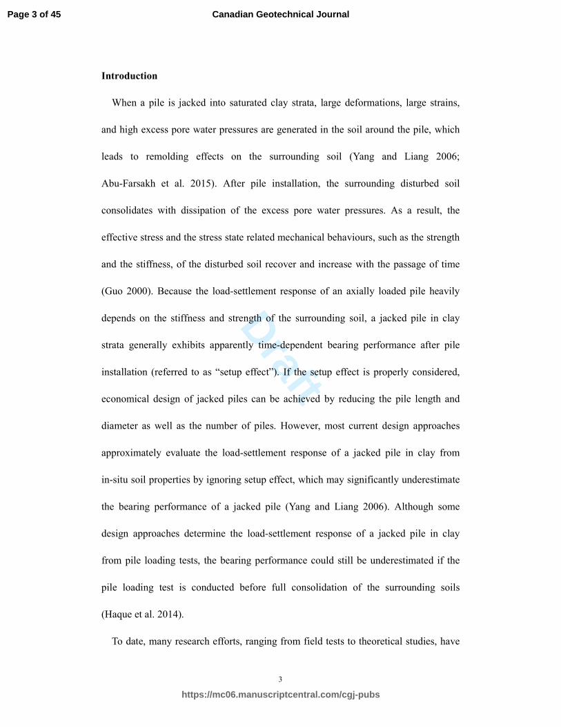
Introduction
When a pile is jacked into saturated clay strata, large deformations, large strains,
and high excess pore water pressures are generated in the soil around the pile, which
leads to remolding effects on the surrounding soil (Yang and Liang 2006;
Abu-Farsakh et al. 2015). After pile installation, the surrounding disturbed soil
consolidates with dissipation of the excess pore water pressures. As a result, the
effective stress and the stress state related mechanical behaviours, such as the strength
and the stiffness, of the disturbed soil recover and increase with the passage of time
(Guo 2000). Because the load-settlement response of an axially loaded pile heavily
depends on the stiffness and strength of the surrounding soil, a jacked pile in clay
strata generally exhibits apparently time-dependent bearing performance after pile
installation (referred to as “setup effect”). If the setup effect is properly considered,
economical design of jacked piles can be achieved by reducing the pile length and
diameter as well as the number of piles. However, most current design approaches
approximately evaluate the load-settlement response of a jacked pile in clay from
in-situ soil properties by ignoring setup effect, which may significantly underestimate
the bearing performance of a jacked pile (Yang and Liang 2006). Although some
design approaches determine the load-settlement response of a jacked pile in clay
from pile loading tests, the bearing performance could still be underestimated if the
pile loading test is conducted before full consolidation of the surrounding soils
(Haque et al. 2014).
To date, many research efforts, ranging from field tests to theoretical studies, have
Page 3 of 45
https://mc06.manuscriptcentral.com/cgj-pubs
Canadian Geotechnical Journal

Draft
4
been performed to investigate the setup effect of a jacked pile in clay (e.g., Skov and
Denver 1988; Lee et al. 2010; Ng et al. 2013a; Ng et al. 2013b; Basu et al. 2014).
Although these studies presented various approaches for assessing the time-dependent
bearing capacity of jacked piles in clayey soils, most of them only focused on the
ultimate bearing capacity of the pile. It is well known that the bearing performance of
a pile can be well reflected by the load-settlement response; while the ultimate
bearing capacity is just one aspect of the bearing performance. Nonetheless, only a
few of previous studies involved the time-dependent load-settlement response of a
jacked pile in clay strata (Abu-Farsakh et al. 2015).
The current approaches for the pile load-settlement analysis can be generally
divided into three broad categories (Ashour et al. 2010): (1) load-transfer methods; (2)
boundary element methods; and (3) finite element methods. Although the finite
element method can consider many complicated factors, such as the effects of pile
installation and subsequent consolidation, its application is limited in practice due to
its high computational requirements (Zhang et al. 2010). Compared with the latter two
methods, the load-transfer method is more attractive in analyzing the load-settlement
response for piles because of its simplicity and capability of incorporating nonlinear
soil behaviour (Guo and Randolph 1997). The load-transfer method quantifies
interaction between pile and soil through a series of independent springs distributed
along the pile shaft and at the pile base. The key of this method is to develop a
rational t-z curve to model the pile-soil interaction behaviour. Generally, the function
for the t-z curve can be determined by either empirical approach or theoretical
Page 4 of 45
https://mc06.manuscriptcentral.com/cgj-pubs
Canadian Geotechnical Journal

Draft
5
analysis (Zhu and Chang 2002). Over the past few decades, the load-transfer method
has been greatly improved by incorporating the soil stress history, the nonlinear soil
behaviour, and the pile installation effects, etc., into the t-z curve (e.g., Ashour et al.
2010; Roberts and Misra 2009; Nanda and Patra 2014; Sheil and McCabe 2016)
Recently, Wang et al. (2012) further developed a load-transfer method by considering
the elastic response of the soil outside the pile-soil interface. However, the evolution
of the mechanical behaviour of the surrounding soil has not yet been incorporated into
the t-z curve to consider the time-dependent pile-soil interaction behaviour. Therefore,
a general analytical approach for evaluating the time-dependent load-settlement
response of a jacked pile is still not currently available.
The primary objective of this paper is to present a nonlinear t-z curve which can
properly describe the time-dependent pile-soil interaction behaviour. The ultimate
desire is to develop a semi-analytical method to estimate the time-dependent
load-settlement response of a jacked pile in clay strata. For this, the evolution of the
mechanical behaviour of the surrounding soil is incorporated into an exponential
function based nonlinear t-z curve to account for the time-dependent pile-soil
interaction behaviour. The in-situ stress history of the natural clay, the pile installation
effect, and the three dimensional strength property of the surrounding soil, all of
which have pronounced effects on the bearing performance of a jacked pile, are also
reasonably incorporated into the proposed t-z curve. An incremental algorithm is then
proposed for capturing the time-dependent bearing performance of a jacked pile in
clay strata. The validity of the proposed approach is examined by comparing the
Page 5 of 45
https://mc06.manuscriptcentral.com/cgj-pubs
Canadian Geotechnical Journal

Draft
6
predicted load-settlement curves with the data obtained from the pile field tests at two
sites. The present approach provides a more rational way to predict the
time-dependent load-settlement response of a jacked pile in clay strata, which has a
great significance in economical design of jacked piles.
Evolution of soil mechanical properties
Changes from pile installation effects
The mechanical behaviour of soils is highly associated with the stress history and
the current stress state. Generally, changes caused by installation of a jacked pile are
more complex than changes caused by construction of a bored pile. Installation of a
jacked pile completely destructures the soil around the pile, creating a large amount of
excess pore water pressures (Zhu and Chang 2002). As a result, both the stress history
and the stress state of the surrounding soil change significantly during pile instillation.
There are two analytical approaches available for evaluating the changes in stress
state caused by pile installation: the strain path method (SPM) and the cavity
expansion method (CEM). Compared with the SPM, although the CEM is a
one-dimensional approach, it has the advantage that a closed-form solution is likely to
model the stress changes during pile installation, which facilitates the analysis
procedure for the subsequent consolidation (Sheil and McCabe 2016). Moreover,
many previous studies demonstrated that the cavity expansion theory can evaluate the
stress state of the surrounding soil with sufficient accuracy (Guo 2000; Randolph
2003). Therefore, the cavity expansion theory is adopted in this study to
Page 6 of 45
https://mc06.manuscriptcentral.com/cgj-pubs
Canadian Geotechnical Journal

Draft
7
approximately assess the stress state of the surrounding soil during pile installation.
In the CEM method, pile installation is simulated by the expansion of a spherical
cavity at the pile tip and a cylindrical cavity around the pile shaft from zero initial
radii to the pile radius, r0. During this process, a plastic region with radius, rp, and
excess pore water pressures are formed in the surrounding clayey soil. So far,
numerous solutions have been proposed to the undrained expansion of a cavity in
clayey soils. The Cam-clay models based solutions appear to have advantages over
others because the effect of the in-situ anisotropic stress, the stress history, and the
large deformation on the expansion response can be reasonably incorporated in the
solutions (Yu 2000; Cao et al. 2001; Chen and Abousleiman 2012). Following the
K0-consolidated anisotropic modified Cam-clay model based solution for cylindrical
cavity expansion (Li et al. 2016) and the modified Cam-clay (MCC) model based
solution for spherical cavity expansion (Cao et al. 2001), the excess pore water
pressures,
,0eu , and the mean effective stress, csp′ , around the pile shaft and tip can
be given as follows
* 2 2
10
02 1
0
,0
4 333 ln
1 2 631
2 3
p m
csm m
p
e m
m MKu p p
K
r
r
η ςςς−
− −
−′ ′ + ± +
= + − −
(1)
0
OCR
2csp p
Λ
=
′ ′
(2)
where m=1 and m=2 indicate the cylindrical case (Li et al. 2016) and the spherical
case (Cao et al. 2001), respectively. The plus sign is taken when 01K ≤ ; conversely,
the minus sign is taken when 01K > . K0 is the coefficient of earth pressure at rest.
( )6sin '/ 3 sin 'M φ φ= − is the slope of the critical state line. 'φ is the effective
Page 7 of 45
https://mc06.manuscriptcentral.com/cgj-pubs
Canadian Geotechnical Journal

Draft
8
internal friction angle. 0p′ is the in-situ mean effective stress. * * OCR 1p Mη −= is
the relative stress ratio at the elastic-plastic (EP) boundary. OCR is the
overconsolidation ratio. * 2 2
0M M η= − is the relative stress ratio at the critical
state. ( )0 0 0/3 1 2 1K Kη = − + is the initial stress ratio. 1 /κ λΛ = − is the
plastic volumetric strain ratio. κ and λ are the slopes of the swelling line and the
loading line, respectively. ς is a parameter to simplify the expressions. pr is the
radius of the plastic region around the cavity, which can be determined by the volume
conservation condition and the yield function of MCC model by ignoring higher order
term of (σ'rp-σ'h0)/G0. The expressions of pr and ς are as follows
( )( )0
0
1
0
2
1
m
p
rp h
m G
m
r
r σ σ
+
=+ −′ ′
(3)
( ) ( )
( )
2 22
0 0
0
2 3 2 1 9 1
3 2 1
M K K
Kς
+ − −
+
= (4)
where *00
/ 3mphrp mpσ σ η= +′ ′ ′ is the radial effective stress at the EP boundary. 0h
σ ′
is the in-situ horizontal effective stress. The in-situ shear modulus, 0
G , is defined
as
( )( )
00
3 1 2
2 1
v pG
v
υκ
′ ′−=
′+ (5)
where υ is the specific volume; and v′ is effective Poisson’s ratio.
Because pile installation not only changes the stress state of the surrounding soil
but also erases the in-situ stress history, i.e., the OCR of the surrounding soil is equal
to unity after pile installation regardless of the initial value of OCR (Randolph and
Wroth 1981). Hence, the surrounding remoulded soil exhibits the mechanical
behaviour similar to the normally consolidated clay after pile installation. Based on
Page 8 of 45
https://mc06.manuscriptcentral.com/cgj-pubs
Canadian Geotechnical Journal

Draft
9
the MCC model, the undrained shear strength of the surrounding soil before and after
pile installation, ,0utcs and ,utc ts , can be expressed in terms of triaxial compression,
respectively, as follows
0,0
1 OCR
2 2utcMps
Λ
= ′ (6)
,
1 1
2 2utc t tMps
Λ
= ′ (7)
where tp ′ is the mean effective stress of the remoulded soil after pile installation and
will be determined in the following section.
Changes from subsequent consolidation
After pile installation, the disturbed soil around the pile consolidates with radial
dissipation of the excess pore water pressures, as shown in Fig. 1. The surrounding
disturbed soil experiences an increase in the effective stress during consolidation,
which leads to the increase in the strength and the stiffness of the soil. Because the
surrounding soil experiences a process like slight unloading and the corresponding
strain is relatively small during consolidation, it can be approximately assumed that
the soil deforms elastically (Guo 2000). Based on the assumption that the soil deforms
elastically, Randolph and Wroth (1979) presented a closed-form analytical solution
for the radial consolidation of the soil around a jacked pile. The expression of the
excess pore water pressures at any time during consolidation can be given as
(Randolph and Wroth 1979)
( ) ( )2
, 1n 0 2 01
n hn n
C
e t nn
tu J r C Y rC e λλ λ
∞
=
− = +∑ (8)
where J0 and Y0 are zero-order Bessel functions of the first and second kind,
Page 9 of 45
https://mc06.manuscriptcentral.com/cgj-pubs
Canadian Geotechnical Journal

Draft
10
respectively; ( ) ( )2 1 / 1 2h h wC k v G vγ′ ′− −= is the coefficient of consolidation for
radial horizontal drainage; hk is the horizontal coefficient of permeability; and wγ
is the unit weight of water. The integration constants C1n and C2n, and the eigenvalues
of the Bessel function λn can be determined by the following equations
02
0
( )
( )n
nn
J RC
Y R
λλ
=− (9)
( ) ( )
( ) ( )
00 0 0
0
00 0
0
1 2
( )
( )
( )
( )
d
nn ne
n
nn n
nd
R
nR
r
r
J Ru J r Y r rdr
Y R
J RJ r Y r rdr
Y R
C
λλ λ
λ
λλ λ
λ
−
=
−
∫
∫ (10)
( ) ( )0 0 01 0 1( ) 0( )n n n nr rY R J J YRλ λ λλ =− (11)
where R is a radial distance beyond which the excess pore water pressures can be
neglected, and can be empirically taken as 5-10 times rp (Guo 2000). Generally, there
are numerous constants 1nC , 2nC and λn that can satisfy Eq. (8) because the Bessel
functions are oscillating functions. However, in practical calculating, the first 50 items
can yield sufficient accuracy.
With Eq. (8), the average consolidation degree of the surrounding soil, tU , can be
given as
0
0
,
0
1e t
e
R
r
t R
r
u
u
rdrU
rdr= −
∫
∫ (12)
During pile installation, a critical state region is developed around the pile due to
the severe squeezing and shearing effects. For soils at the critical state, the mean
effective stress p'cs keeps unchanged regardless of further shearing and squeezing.
Hence, after pile installation, the mean effective stress p't increases from p'cs with
Page 10 of 45
https://mc06.manuscriptcentral.com/cgj-pubs
Canadian Geotechnical Journal

Draft
11
dissipation of the excess pore water pressures. However, because of the stiffness
discrepancy of the soil around the pile, the increase of the effective stress does not
strictly match the dissipation of excess pore water pressures and the mean total stress
pt exhibits relaxation effects during consolidation. These effects can be properly
modeled by Biot’s coupled consolidation theory along with the nonlinear stress-strain
behaviour of soil. Nonetheless, if these effects are taken into account, it is extremely
complex to derive a closed-form solution for consolidation of the soil around pile. To
facilitate the application of the proposed approach, Terzaghi’s radial consolidation
theory and an effective stress transfer parameter χ (Randolph and Wroth 1979) are
adopted to approximately evaluate the mean effective stress after pile installation.
Based on the principle of effective stress, the mean effective stress after pile
installation can be given as follows
( ),,0t cs e teu up p χ −= +′ ′ (13)
where χ is the aforementioned effective stress transfer parameter under the plane
strain condition, defined as ( )1 / 3 1v vχ = −+ ′ ′ .
With Eq. (13), the change in the mean effective stress after pile installation can be
quantified using a dimensionless factor, named the mean effective stress ratio (ESR),
as follows
0
tpESR
p
′=
′ (14)
Making use of Eqs. (5), (7) and (14), the undrained shear strength ,utc ts in terms of
triaxial compression and the shear modulus, tG , of the surrounding disturbed soil at
any time after pile installation can be approximately determined as
Page 11 of 45
https://mc06.manuscriptcentral.com/cgj-pubs
Canadian Geotechnical Journal
Draft
12
( ), ,0
OCRutc t utc
ESRs s Λ= (15)
0 0
0
ttG G ESR G ESR
υ
υ= ≈ (16)
where tυ is the time-dependent specific volume of the surrounding soil after pile
installation. However, if the change of 0/tυ υ is considered, it is extremely difficult to
obtain an analytical solution for the elastic soil displacement outside the shear band
later in the paper. Since the ratio 0/tυ υ of a typical clayey soil after full
consolidation is in the range of 0.93-0.95 (Basu et al. 2013), which has a nearly
negligible effect on the change in the shear modulus, the effect of the change in the
specific volume on shear modulus is neglected in this study to facilitate the following
analysis work.
Time-dependent load-transfer curve
Nonlinear t-z curve for pile-soil interaction
During pile loading, the total displacement of the pile at a given depth consists of
the relative displacement at the pile-soil interface, the displacement of the shear band
as well as the displacement of the soil outside the shear band, as shown in Fig. 2.
Investigations by means of the in-situ test (Caputo and Viggiani 1984), the finite
element analysis (Trochanis et al. 1991), and the theoretical study (Wang et al. 2012)
show that the total displacement is primary the nonlinear displacements developed at
the pile-soil interface and in the shear band adjacent to the pile shaft, whereas the
displacement of the bulk of the soil outside the narrow shear band is relatively small
Page 12 of 45
https://mc06.manuscriptcentral.com/cgj-pubs
Canadian Geotechnical Journal

Draft
13
and largely elastic. Because the shear band forms in a fairly narrow zone adjacent to
the pile shaft and its actual thickness is very difficult to determine, it can be
approximated and simplified as a displacement discontinuity with no physical size in
practice (Lee and Xiao 2001). Based on this approximation, the nonlinear
displacements developed at the pile-soil interface and in the shear band can be
evaluated by a single nonlinear t-z curve. According to the results of laboratory and
field tests (Zhang et al. 2014), the nonlinear relation between the shear stress and the
relative displacement at the pile-soil interface can be well described by a hyperbolic
function or an exponential function. In this study, an exponential function based
load-transfer curve, as shown in Fig. 3, is adopted to model the behaviour of the
pile-soil interface. The expression of the exponential function takes the following
form
( ), ,
, , 1 s z p zb W
s z s za eτ −= − (17)
where ,s zτ and ,p zW are the mobilized shear stress and the corresponding pile-soil
relative displacement at depth z, respectively. ,s za and ,s zb are the model
parameters and ,s za is the asymptote of the load-transfer curve; the product of ,s za
and ,s zb represents the initial stiffness of the load-transfer curve, as shown in Fig. 3.
Taking the derivative of Eq. (17) with respect to ,p zW , the tangent stiffness of per
perimeter of the pile-soil interface, ,sp zK , during loading can be written as
, ,
0, , ,2 s z p zb W
sp z s z s zrK a b eπ −= (18)
The degradation of the stiffness at the pile-soil interface with the increase of shear
displacement, which is commonly observed from pile loading tests, can be well
Page 13 of 45
https://mc06.manuscriptcentral.com/cgj-pubs
Canadian Geotechnical Journal

Draft
14
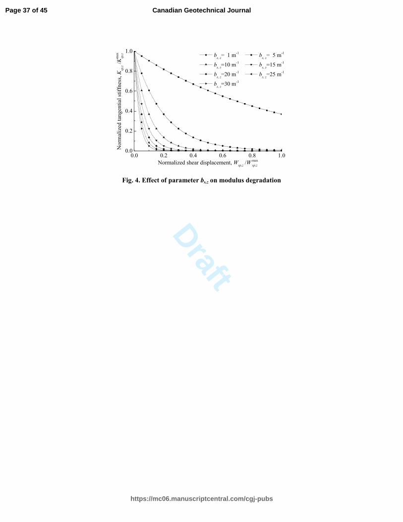
represented by Eq. (18). Fig. 4 shows sample stiffness degradation curves, presented
as the variation of the normalized tangential stiffness, max
, ,/
sp z sp zK K , with the
normalized shear displacement, max
, ,/
sp z sp zW W , generated by Eq. (18). It can be
concluded from Fig. 4 that the parameter ,s zb not only controls the magnitude of
degradation, but also indicates the rate of degradation.
3.2 Displacement of the soil outside the pile-soil interface
Since the soil outside the shear band remains largely elastic, the corresponding
displacement is evaluated based on the procedure proposed by Randolph and Wroth
(1978) for analyzing the elastic displacement of the soil:
0
,
,
1
mz
r z
r
se zr
rW drG r
τ=− ∫ (19)
where 0/ 2z zdP rτ π= is the local shaft stress. zdP is the axial force increments
along the pile shaft at depth z. ,r zG is the shear modulus of the surrounding remolded
soil along the radial direction at depth z. ( )2.5 1mr Lρ ν′= − is the limiting radius
beyond which the shear stress induced by the pile becomes negligible. ρ is the ratio of
soil shear modulus at middepth to that of the pile tip.
Substituting Eq. (16) into Eq. (19), the elastic soil displacement, considering the
pile installation effects, of the surrounding soil can be rewritten as follows
( )0
,,
1
2 lnm
rz
se zr
z
dPW dr
G A B r rπ= −
−∫ (20)
where 0,zG is the in-situ shear stress at depth z. A and B are the parameters to
simplify the expression. The expressions of A and B are as follows
Page 14 of 45
https://mc06.manuscriptcentral.com/cgj-pubs
Canadian Geotechnical Journal
Draft
15
* 2 20
02 2
3 4 3ln
1 2 631
2 tp
pOCR OCRK M
A r UK
η ςς χςΛ Λ
−+ + ±+
= + − − (21)
2t
OCRB Uςχ
Λ
= (22)
According to the relation between the plastic radius rp induced by pile installation
and the maximum influence radius rm of the pile during loading, Eq. (20) can be
integrated in the following two cases:
1) If the plastic radius rp is larger than the maximum influence radius rm, i.e., rp>rm,
integrating Eq. (20) yields
0,
0,
lnln
ln2se z
z m
z A B r
A B r
dPW
BGπ−
=−
(23a)
2) Oppositely, when the plastic radius rp is less than the maximum influence radius
rm, i.e., rp≤rm, Eq. (20) can be integrated to give
0,
0,
lnln
2 ln
B
z mse z
z p p
dP A B r rW
BG A B r rπ
− = −
(23b)
It should be noted that the surrounding soil is assumed to deform elastically during
consolidation, and hence rp in Eqs. (23a) and (23b) is only used to determine the
range in which the stress state of the soil is changed by pile installation.
From Eq. (23), the elastic stiffness of the soil around per unit length of pile shaft,
,se zK , can be written as follows
0,
0
0,
0
,
2
lnln
ln
2
lnln
ln
z
m
z
B
m
p p
p m
se z
p m
BG
A B r
A B r
K BG
A B r r
A B r r
r r
r r
π
π
−
−
−
−
≤
>
= (24)
Page 15 of 45
https://mc06.manuscriptcentral.com/cgj-pubs
Canadian Geotechnical Journal
Draft
16
As shown in Fig. 2, the total shaft displacement, Ws,z, is the sum of the pile-soil
relative displacement ,sp zW and the surrounding elastic displacement ,se zW , i.e.,
, , ,s z sp z se zW W W+= (25)
Based on Eq. (25), the generalized stiffness per unit length of pile shaft, ,s zK ,
defined as the force per displacement, can be given as
, ,
,
, ,
sp z se z
s z
sp z se z
KK K
K K+= (26)
Load-transfer curve for pile base
Results from the load tests on instrumented piles (Zhang et al. 2014) indicated that
the nonlinear load-displacement relationship developed at the pile base was also
conformed to a hyperbolic function or an exponential function. Similar to the
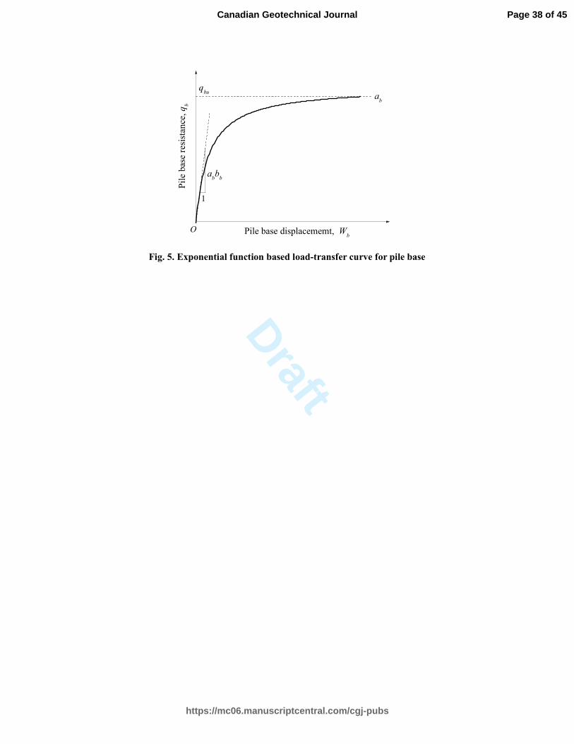
proposed load-transfer curve for pile shaft, the relation between the mobilized pile
base resistance, bq , and the corresponding displacement, bW , can be expressed by
an exponential function as follows
( )1 b bb W
b bq a e−= − (27)
where the model parameter ba can be taken as the ultimate pile base resistance; the
parameter bb controls the magnitude and the rate of stiffness degradation at the pile
base; and the product of ba and bb represents the initial stiffness of the soil at the
pile base, as shown in Fig.5.
With Eq. (27), the tangential stiffness of the pile base during loading can be given
as
b bb W
b p b bK A a b e−= (28)
Page 16 of 45
https://mc06.manuscriptcentral.com/cgj-pubs
Canadian Geotechnical Journal

Draft
17
where 2
0pA rπ= is the cross-sectional area of the pile.
Determinations of the values of model parameters
Generally, the values of the model parameters can be obtained experimentally
either from the back-analysis of field load test results or from laboratory experimental
tests (Zhang et al. 2010). However, these experiment methods are not only
time-consuming, but also incapable of incorporating the evolution of the mechanical
behaviour of the soil around the pile. Hence, the experiment methods have great
limitations. In the following, a general theoretical approach is proposed to determine
the time-dependent ultimate pile shaft and base resistances.
As mentioned previously, the model parameters ,s za and b
a are the asymptote of
the load-transfer curves for the pile shaft and the pile base, respectively. Hence, the
parameters ,s za and b
a can be determined as follows
, ,s z su za τ= (29)
b bua q= (30)
where ,su zτ and buq are the ultimate pile shaft resistance at depth z and the ultimate
pile base resistance, respectively.
Fig. 6 shows the most likely stress state at failure along with the corresponding
Mohr’s stress circle for a soil element adjacent to the pile shaft during loading of the
pile as shown in Fig. 2. Based on the shearing pattern of the soil element during pile
loading, the radius of the Mohr’s stress circle is defined as the undrained shear
strength of the soil under the plane strain condition, ,ups zs . As discussed before, the
soil adjacent to the pile can be approximately taken as normally consolidated clay
Page 17 of 45
https://mc06.manuscriptcentral.com/cgj-pubs
Canadian Geotechnical Journal
Draft
18
after pile installation. For the normally consolidated clay, the cohesion intercept can
be ignored. Thus, the failure-envelope in Fig. 6 passes through the origin of
coordinates. After pile installation, the radial effective stress becomes the largest
component among the three normal stresses ( , ,r zθσ σ σ′ ′ ′ ). Hence, the failure envelope
is most likely to be tangent to the effective stress circle at point B, while the
corresponding stress state at the pile-soil interface is located at point A. From the
simple geometry shown in Fig. 6, the ultimate shaft resistance can be expressed as
, ,cos
su z ups zsτ φ′= (31)
The three-dimensional strength of soil under arbitrary shear condition can be
properly modeled by the SMP or Lade’s criteria (Matsuoka and Sun 2006). Based on
the stress transformed method proposed by Matsuoka et al. (1999) and the SMP
criterion, the undrained shear strength under the plane strain condition can be
evaluated by the undrained shear strength under the triaxial compression as
2
3 3 sin
2 cos 2 sin
f
f f
ups utcM
s sϕ
ψ ϕ+= (32)
where f
ϕ and f
ψ are the stress transformed parameters, which are given as
follows
2sin
9 3f
M
Mϕ =
+
(33)
3/2
1
2
1 3cos sin cos3
3 2 sinf f
f
ψ ϕ θϕ
−
= − + (34)
where Lode’s stress angle θ is equal to / 6π under the plane strain condition.
Combining Eqs. (15), (29), (31) and (32), the model parameter ,s za can be finally
Page 18 of 45
https://mc06.manuscriptcentral.com/cgj-pubs
Canadian Geotechnical Journal
Draft
19
determined as
, ,02
3 3sin cos
2 cos 2 sin
f
f f
s z utc
ESR
OCRa
Ms
ϕ φ
ψ ϕΛ
′=
+ (35)
For a pile in clayey soils, the contribution of tip resistance to total pile capacity is
quite small compared with the resistance developed along the pile shaft because of the
mobilization of skin friction. Hence, it is sufficient to evaluate the ultimate end
resistance buq by the following equation (Saldivar and Jardine 2005)
bu c utcsq N= (36)
where cN is the end-bearing capacity factor and usually taken as 9.0 for clayey
soils.
From Eqs. (15) and (30) along with Eq. (36), the model parameter b
a can be given
as
,0c utcbN
ESR
OCRa sΛ= (37)
According to the initial condition, the initial tangential stiffness of the load-transfer
curve for the pile shaft should be equal to the elastic stiffness of the surrounding soil.
Hence, the model parameter ,s zb can be determined from Eqs. (18) and (24) as
follows
0,
0, 0
0,
00
,
,
lnln
ln
lnln
ln
z
p m
s z
m
z
p mB
m
m p
s z
s z
BG
BG
a
r rA B r
aA B r
br r
A B r rr
A B r r
r
> −
−
< − −
= (38)
From the simple method of Randolph and Wroth (1978), the elastic response of the
pile base can be evaluated by a rigid circular disc acting on the surface of a
Page 19 of 45
https://mc06.manuscriptcentral.com/cgj-pubs
Canadian Geotechnical Journal

Draft
20
homogeneous elastic stratum. The corresponding elastic stiffness of the pile base can
be written as
0 0,
4
1e b
rGK
v=
′− (39)
Introducing Eq. (16) into Eq. (39), the elastic stiffness of the pile base considering
the pile installation effects can then be rewritten as
0 0,
4
1e b
rGK ESR
v=
′− (40)
Based on the definition of the product of ab and bb for the load-transform curve, the
parameter bb can be determined by combing Eqs. (28) and (40) as
( )0
0
4
1b
b
G ESR
r ab
vπ=
′− (41)
Prediction of time-dependent bearing performance
Incremental algorithm for load-settlement analysis
Based on the proposed load-transfer curves for the pile shaft and the pile base, the
time-dependent bearing performance of a jacked pile in clay strata can be evaluated
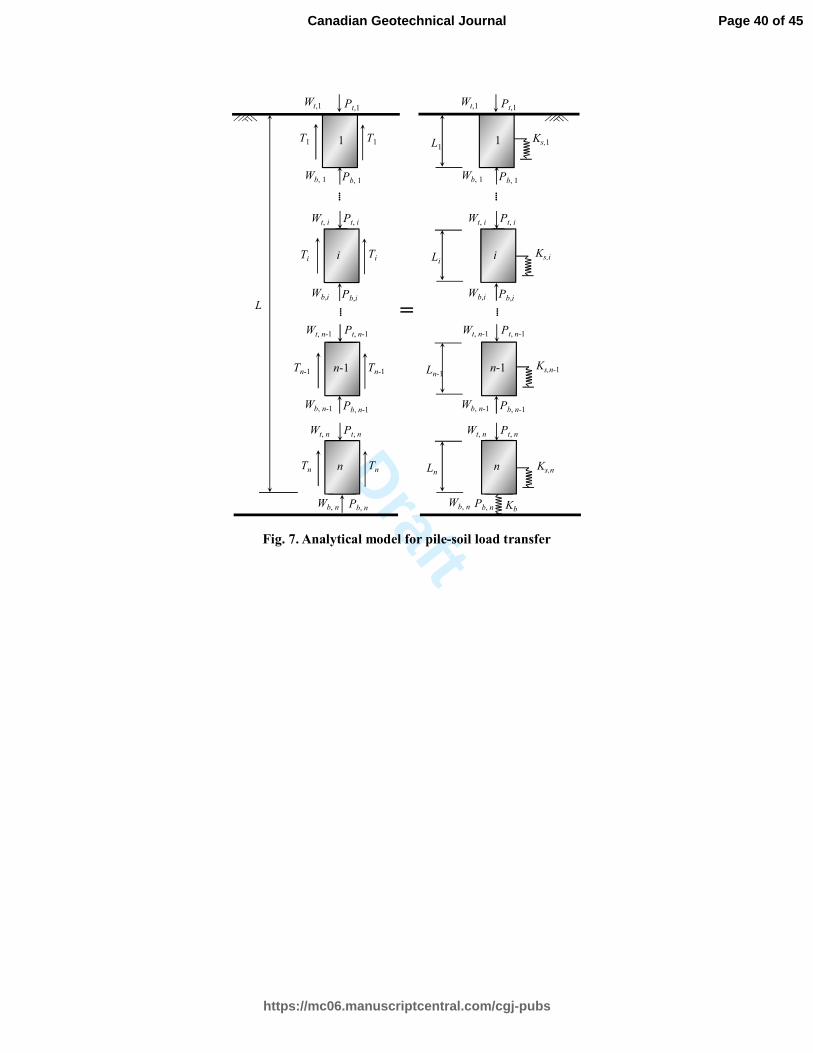
by the load transfer method. As shown in Fig. 7, the load transform method models
the pile as a series of elements supported by discrete nonlinear springs. The bearing
behaviours of the pile shaft and the pile base are represented by the springs distributed
along the pile shaft and at the pile base, respectively. Here, the pile is divided equally
into n segments, with the length of each part Ln=L/n. The discrete segments are
numbered from the pile top to the pile base. The schematic diagram of this
discretization is shown in Fig. 7. When n is large enough, the thickness of each
Page 20 of 45
https://mc06.manuscriptcentral.com/cgj-pubs
Canadian Geotechnical Journal

Draft
21
segment is so small that a linear variation can be assumed for the distribution of the
axial force in each segment to facilitate analyses.
In this study, the original iterative procedure proposed by Coyle and Reese (1996)
for the load-transfer method is modified and developed to accommodate the
incremental algorithm. The present assessment procedure assumes a series of small
displacement increments, ,n bWδ , at the pile base. For each pile base displacement
increment, the corresponding pile base load increment, ,n bPδ , at a given time after
pile installation can be calculated as follows
, ,bn b n bP K Wδ δ= (42)
Assuming that the displacement increment at the middle height of segment n,
,sn mWδ , is equal to the current pile base displacement increment ,n bWδ , the
corresponding axial force increment at the top of segment n, ,n tPδ , can be obtained as
, , , ,nn t sn m sn m n bP K W L Pδ δ δ= + (43)
where ,sn mK is the pile shaft stiffness at the middle height of the segment n. It should
be noted that the required displacement ,spn mW and ,n b
W in Eqs. (18) and (28) used to
determine the tangential stiffness ,sn mK and bK are equal to zero for the first
displacement increment.
Following the assumption of the linear variation of the load distribution along the
segment, the elastic deformation increment at the midpoint of segment n, ,en mWδ ,
can be calculated as
( ), ,
,2
n
p p
n m n b
en m
P P LW
E A
δ δδ
+= (44)
where Ep is Young’s modulus for the pile material. ( ), , , / 2n m n t n bP P Pδ δ δ= + is the
Page 21 of 45
https://mc06.manuscriptcentral.com/cgj-pubs
Canadian Geotechnical Journal
Draft
22
axial force increment at the midpoint of segment n.
With the assumed pile base displacement increment ,n bWδ and the elastic
deformation increment ,en mWδ , the updated midpoint displacement increment of
segment n, ,sn mWδ ′ , can then be expressed as
, , ,sn m en m n bWW W δδ δ′ = + (45)
When the difference between the two displacement increments ,sn mWδ ′ and
,sn mWδ is greater than a specified tolerance, the above procedure will continue to
repeat with the new displacement increment ,sn mWδ ′ until the convergence is
achieved. The displacement increment at the top of segment n, ,n tWδ , can be finally
obtained as
( ), ,
, ,
2
n
n t n b
p p
n t n bP P LW W
E A
δ δδ δ
+= + (46)
From Eq. (17), the pile-soil relative displacement increment at the midpoint of
segment n, ,spn mWδ , can be derived as
, ,
0 ,
,
,
ln 12
sn m sn m
sn m
spn m
sn m
K W
r aW
b
δπ
δ
− −
= (47)
where ,sn ma and
,sn mb are the model parameters of the load-transfer curve at the
midpoint of segment n, respectively.
Consecutively, taking the load and displacement increments at the top of each
segment as the load and displacement increments at the base of the upper segment, the
load and displacement increments of each segment can be obtained by repeating the
above procedure from segment n to segment 1.
For successive pile base displacement increments, a series of corresponding load
Page 22 of 45
https://mc06.manuscriptcentral.com/cgj-pubs
Canadian Geotechnical Journal
Draft
23
and displacement increments of each segment can be obtained by conducting the
above procedure. In each round of calculating, the displacement increments at the
middle height of the each segment and the pile base are accumulated to determine the
tangential stiffness ,sn mK and b
K for the next round. The pile head load, t
P , and
displacement, t
W , will be the accumulated load and displacement increments at the
top of segment 1, respectively.
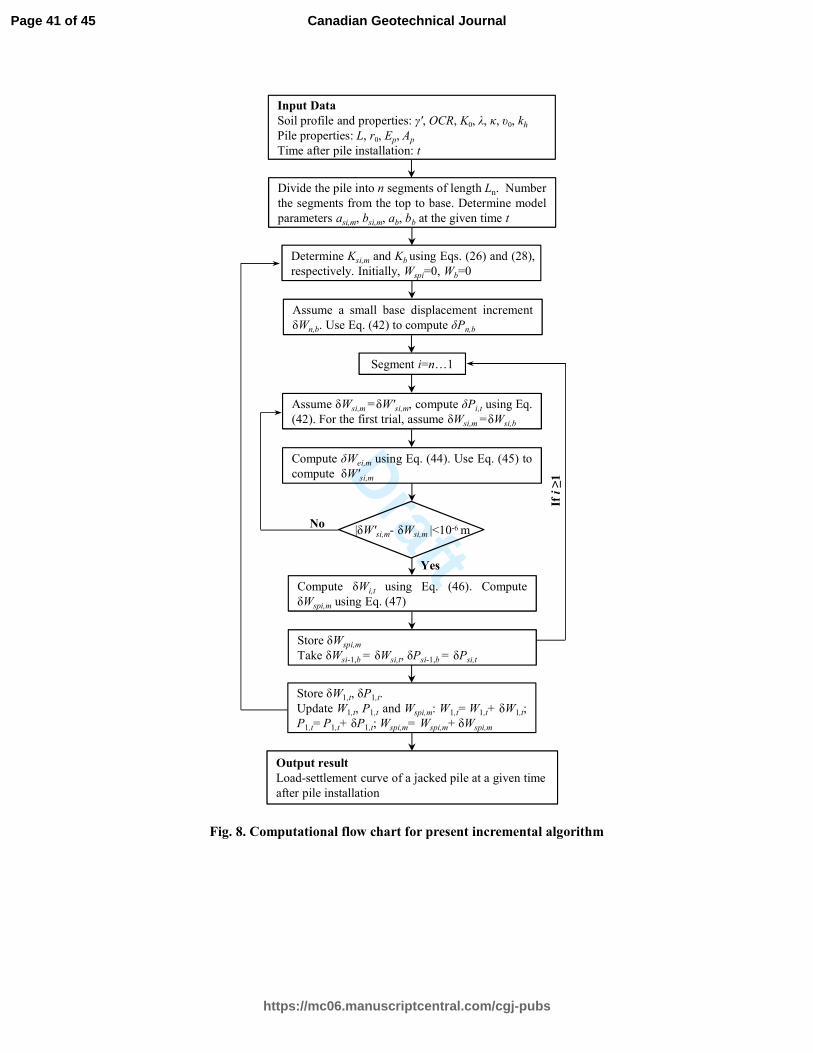
Computational scheme
Based on the proposed incremental algorithm, the corresponding computational
flow chart, as shown in Fig.8, is drew for the general framework of the developed
technique. Following the flow chart, a MATLAB software based computer code is
developed to capture the time-dependent bearing performance of a jacked pile in clay
strata. The present approach only requires a few seconds to predict the load-settlement
curve of a pile at a given time after pile installation, which demonstrates the present
approach is quite economical and efficient.
Verification of proposed approach
The proposed approach and procedure are verified by comparing the predicted
results with the time-dependent load-settlement responses of jacked piles in (1)
Shanghai soft clay strata; and (2) Quebec Champlain clay.
Case 1: Pile in Shanghai soft clay strata
The pile loading tests chosen for comparison were conducted by authors at Zhoupu
town, Pudong District of Shanghai. The site investigation and the field boring log
Page 23 of 45
https://mc06.manuscriptcentral.com/cgj-pubs
Canadian Geotechnical Journal

Draft
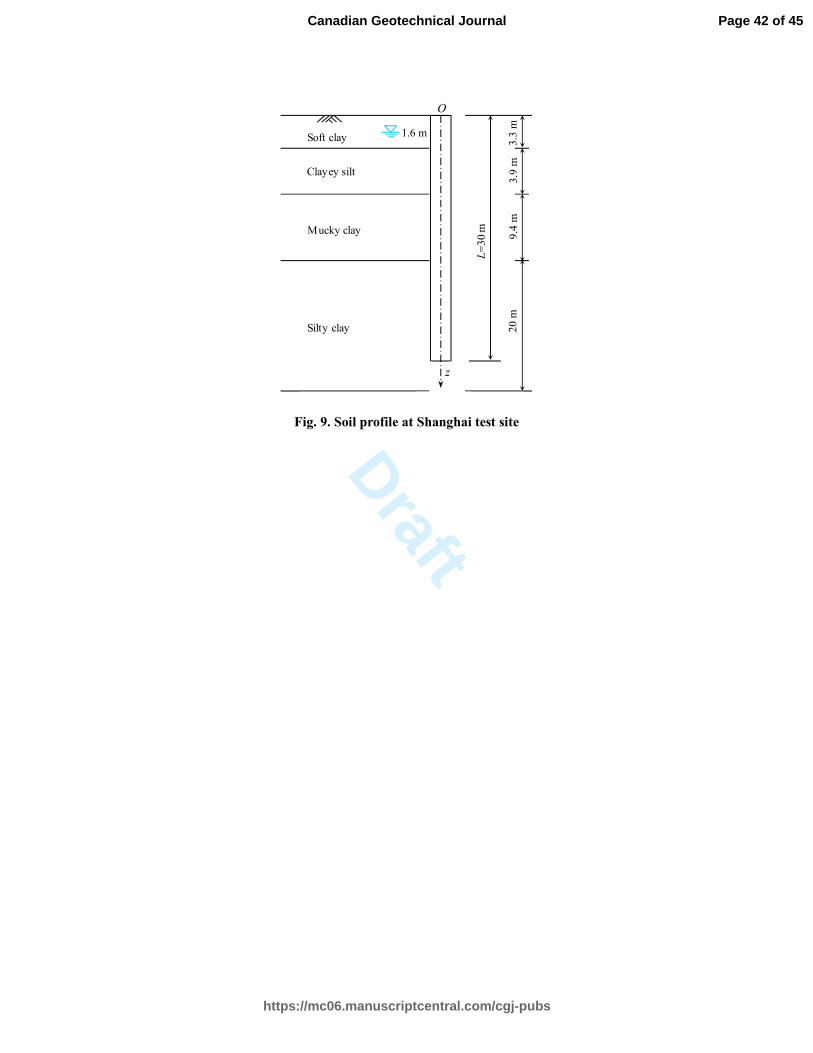
24
show that the soil strata mainly consist of soft clay, clayey silt, mucky clay and silty
clay at different depths, as shown in Fig. 9. The soils are normally consolidated with
OCRs in the order of 1.1. The groundwater table lies at a depth of 1.3 m below the
ground surface. The soil properties, from comprehensive laboratory testing on high
quality Shelby tube samples retrieved from the boreholes, are summarized in Table 1.
Three concrete piles, each with diameter of 0.35 m, were jacked to the embedment
depth of 30 m. The elastic modulus Ep of the concrete pile is equal to 40 GPa. The
static loading test was conducted on the three test piles, TP1, TP2 and TP3, at 7 days,
25 days and 65 days after pile installation, respectively. The reloading effects on the
load-settlement response were effectively avoided in the designed pile testing
program because each pile was tested only once. The quick test procedure suggested
by ASTM D1143 was adopted for the static loading tests. Based on the quick test
procedure, the loads were applied step-by-step with an increment of 5% of the
anticipated failure load. During each load interval, the settlement at the pile head was
recorded after the load had been applied and maintained for a time interval of 5 min.
Using the soil properties listed in Table 1, the proposed approach is applied to
predict the load–settlement responses of the test piles. In the calculation, the values of
the effective Poison’s ratio v′ of the surrounding soils are assumed to be 0.35. A
typical value of 0.8 is assumed for Λ , because the parameter Λ is essentially a
constant, with an average value of 0.8 for natural intact clays under the plane strain
shearing condition (Cao et al. 2001). The values of K0 are estimated by the empirical
formula suggested by Manyne and Kulhawy (1982) as follows
Page 24 of 45
https://mc06.manuscriptcentral.com/cgj-pubs
Canadian Geotechnical Journal

Draft
25
sin0 (1 sin )OCRK φφ ′′= − (48)
Fig. 10 shows the comparisons between the measured results from the loading tests
and the predicted load-displacement curves. As seen in the figure, the predicted
load-transfer curves agree well with the field observations. The good agreements
demonstrate that the proposed semi-analytical approach can yield reasonable
prediction for the time-dependent load-settlement responses of the test piles. It is also
interesting to note that both the stiffness and the ultimate bearing capacity of the pile
increase substantially with time, but the increase magnitude and the increase rate
decrease with time after pile installation. This is because the hydraulic gradient of the
excess pore water pressures decreases with consolidation time, which results in a
faster increase in the strength and the shear modulus of the surrounding soils
immediately after pile installation and followed by a slower rate in the increase. This
phenomenon was also observed in the field test by Roy et al. (1981).
Case 2: Pile in Quebec Champlain clay
Konrad and Roy (1987) performed static loading tests on a jacked pile at various
times after pile installation to investigate the time-dependent bearing performance of
jacked piles in clay. The pile test site is located at St-Alban, 80 km west of Quebec
City. In the test, a closed-ended steel pile with diameter of 0.22 m was firstly jacked
vertically to a depth of 7.6 m below the ground surface. The static load tests were then
conducted on the pile at time intervals of 4 days, 8 days and 33 days after completion
of installation. During the process of pile loading, the loads were applied step-by-step
with a small increment of 6.67 kN until pile failure. Each load was maintained for a
Page 25 of 45
https://mc06.manuscriptcentral.com/cgj-pubs
Canadian Geotechnical Journal

Draft
26
period of 15 min.
The soil within the embedment depth of the test pile is soft silty marine clay. The
groundwater table was located at 0.4 m below the ground surface. The clay deposit is
slightly overconsolidated with an OCR of about 2.1. The coefficient of earth pressure
at rest K0 is about 0.63. The ratio of the shear modulus over the mean effective stress,
0/G p′ , is in the order of 90. The effective internal friction angle 'φ , in terms of
triaxial compression tests, ranges from 27° to 30°. From depths of 2.0 m-6 m, the
in-situ effective vertical stress, 0z
σ ′ , increases linearly from 16 kPa to 36 kPa. The
horizontal coefficient of consolidation hC is approximately equal to 73 10−× m2/s.
Taking the median value of 28φ °′ = and typical values of 0.75Λ = and 0.3v′ = ,
the time-dependent load-settlement responses of the test pile are predicted with the
parameters of the St-Alban clay. Fig. 11 shows the load-settlement curves obtained
from the proposed approach along with the results derived from the field
measurements. This figure demonstrates satisfactory agreements between the
predicted and field-measured results, although a stiffer and stronger axial response is
predicted for the pile at 4 days after pile installation. The reason is properly that the
recovery of the collapsed soil structures and the bonds between soil particles (referred
to as thixotropy) is not completed in a short time interval after pile installation.
Although the thixotropic effects are not incorporated in the present approach because
of the extreme complexity, the proposed semi-analytical approach can yield
reasonable predictions for load-settlement responses of a jacked pile in clay strata
beyond certain time after pile installation, especially for the long-term load-settlement
Page 26 of 45
https://mc06.manuscriptcentral.com/cgj-pubs
Canadian Geotechnical Journal

Draft
27
behaviour.
Conclusions
In this paper, a semi-analytical approach has been developed to evaluate the
time-dependent load-settlement response of a jacked pile in clay strata. This approach
adopts the exponential function-based load-transfer curves to describe the nonlinear
pile-soil interaction behaviour. The evolution of the mechanical behaviour of the
surrounding soil, which is the primary cause for the time-dependent load-settlement
response, is properly incorporated in the proposed nonlinear load-transfer curves. An
incremental algorithm-based iterative procedure is developed to enable the
time-dependent load-settlement response to be determined using the presented
load-transfer curves. The proposed technique is implemented by a highly efficient
computer program based on the MATLAB software. Case studies of pile loading tests
at two different sites indicate that the proposed procedure can be applied to predict the
time-dependent load-settlement responses with reasonable accuracy.
The input parameters required for the proposed approach are the pile properties and
the in-situ soil profile and properties. These parameters can be easily determined from
in situ tests or laboratory experiments. The thixotropy is not considered in the present
approach, thus the proposed approach may yields a stronger axial response at a short
time interval after pile installation. It is worth noting that the present approach can be
modified to incorporate the pile installation effects when assessing the load-settlement
response of pile groups.
Page 27 of 45
https://mc06.manuscriptcentral.com/cgj-pubs
Canadian Geotechnical Journal

Draft
28
Acknowledgments
The authors are grateful for the support provided by the National Natural Science
Foundation of China (Grant No. 41272288) for this research work. The anonymous
reviewers’ comments have improved the quality of this paper and are also greatly
acknowledged.
References
Abu-Farsakh, M., Rosti, F., and Souri, A. 2015. Evaluating pile installation and the
following thixotropic and consolidation setup by numerical simulation for full
scale pile load tests. Canadian Geotechnical Journal, 52(11): 1734–1746.
Ashour, M., Norris, G.M., Elfass, S., and Al-Hamdan, A.Z. 2010. Mobilized side and
tip resistances of piles in clay. Computers and Geotechnics, 37(7–8): 858–866.
Basu, P., Prezzi, M., Salgado, R., and Chakraborty, T. 2013. Shaft resistance and setup
factors for piles jacked in clay. Journal of Geotechnical and Geoenvironmental
Engineering, 10.1061/(ASCE)GT.1943-5606.0001018, 04013026.
Cao, L.F., Teh, C.I., and Chang, M.F. 2001. Undrained cavity expansion in modified
Cam clay I: theoretical analysis. Géotechnique, 51(4): 323–334.
Caputo, V., and Viggiani, C. 1984. Pile foundation analysis: a simple approach to
nonlinearity effects. Rivista Italiana di Geotecnica, 18(2): 32–51.
Chen, S.L., and Abousleiman, Y.N. 2015. Exact undrained elasto-plastic solution for
cylindrical cavity expansion in modified Cam Clay soil. Géotechnique, 62(5):
Page 28 of 45
https://mc06.manuscriptcentral.com/cgj-pubs
Canadian Geotechnical Journal
Draft
29
447–456.
Coyle, H.M., and Reese, L.C. 1996. Load transfer for axially loaded piles in clay.
Journal of Soil Mechanics & Foundations Div, 92(2): 1–26.
Guo, W.D. 2000. Visco-elastic consolidation subsequent to pile installation.
Computers and Geotechnics, 26(2): 113–144.
Guo, W.D., and Randolph, M.F. 1997. Vertically loaded piles in non-homogeneous
media. International Journal for Numerical and Analytical Methods in
Geomechanics, 21(8): 507–532.
Haque, M.N., Abufarsakh, M., Chen, Q.M., and Zhang, Z.J. 2014. Case study on
instrumenting and testing full-scale test piles for evaluating setup phenomenon.
Transportation Research Record, 2462: 37–47.
Konrad, J.M., and Roy, M. 1987. Bearing capacity of friction piles in marine clay.
Géotechnique, 37(2): 163–175.
Lee, K.M., and Xiao, Z.R. 2001. A simplified nonlinear approach for pile group
settlement analysis in multilayered soils. Canadian Geotechnical Journal, 38(5):
1063-1080.
Lee, W., Kim, D., Salgado R, and Zaheer, M. 2010. Setup of driven piles in layered
soil. Soils and Foundations, 50(5): 585–598.
Li, L., Li, J.P., and Sun, D.A. 2016. Anisotropically elasto-plastic solution to
undrained cylindrical cavity expansion in K0-consolidated clay. Computers and
Geotechnics, 73: 83–90.
Matsuoka, H., and Sun, D.A. 2006. The SMP Concept-based 3D Constitutive Models
Page 29 of 45
https://mc06.manuscriptcentral.com/cgj-pubs
Canadian Geotechnical Journal
Draft
30
for Geomaterial. Taylor and Francis.
Matsuoka, H., Yao, Y.P., and Sun, D.A. 1999. The Cam-clay model revised by the
SMP criterion. Soils and Foundations, 39(1): 81–95.
Mayne, P.W., and Kulhawy, F.H. 1982. K0-OCR relationships in soils. Journal of
Geotechnical Engineering, 108(6): 851–872.
Nanda, S., and Patra, N.R. 2013. Theoretical load-transfer curves along piles
considering soil nonlinearity. Journal of Geotechnical and Geoenvironmental
Engineering, 10.1061/(ASCE)GT.1943-5606.0000997: 91–101.
Ng, K.W., Roling, M., AbdelSalam, S.S., Suleiman, M.T., and Sritharan, S. 2013. Pile
setup in cohesive soil. I: experimental investigation. Journal of Geotechnical and
Geoenvironmental Engineering, 139(2): 199–209.
Ng, K.W., Suleiman, M.T., and Sritharan, S. 2013. Pile setup in cohesive soil. II:
analytical quantifications and design recommendations. Journal of Geotechnical
and Geoenvironmental Engineering, 139(2): 210–222.
Randolph, M.F. 2003. Science and empiricism in pile foundation design.
Géotechnique, 53(10): 847–875.
Randolph, M.F., and Worth, C.P. 1979. An analytical solution for the consolidation
around a driven pile. International Journal for Numerical and Analytical Methods
in Geomechanics, 3(3): 217–229.
Randolph, M.F., and Wroth, C.P. 1978. An analysis of the vertical deformation of pile
groups. Géotechnique, 29(4): 423-439.
Randolph, M.F., and Wroth, C.P. 1981. Application of the failure state in undrained
Page 30 of 45
https://mc06.manuscriptcentral.com/cgj-pubs
Canadian Geotechnical Journal

Draft
31
simple shear to the shaft capacity of driven piles. Géotechnique, 31(1): 143–157.
Roberts, L.A., and Misra, A. 2009. Service limit state resistance factors for drilled
shafts. Géotechnique, 59(1): 53–61.
Roy, M., Blanchet, R., Tavenas, F., and Rochelle, P.L. 1981. Behaviour of a sensitive
clay during pile driving. Canadian Geotechnical Journal, 18(1): 67–85.
Saldivar, E.E., and Jardine, R.J. 2005. Application of an effective stress design
method to concrete piles driven in Mexico City clay. Canadian Geotechnical
Journal, 42(6): 1495–1508.
Sheil, B.B., and McCabe, B.A. 2016. An analytical approach for the prediction of
single pile and pile group behaviour in clay. Computers and Geotechnics, 75: 145–
158.
Skov, R., and Denver, H. 1998.Time dependence of bearing capacity of piles. Proc.
3rd Int. Conf. Application of Stress-Wave Theory to Piles, Ottawa, Ont., pp. 879–
888.
Trochanis, A.M., Bielak, J., and Christiano, P. 1991. Three dimensional nonlinear
study of piles. Journal of Geotechnical Engineering, 117(3): 429–447.
Wang, Z.J., Xie, X.Y., and Wang, J.C. 2012. A new nonlinear method for vertical
settlement prediction of a single pile and pile groups in layered soils. Computers
and Geotechnics, 45: 118–126.
Yang, L., and Liang. R. 2006. Incorporating set-up into reliability-based design of
driven piles in clay. Canadian Geotechnical Journal, 43(9): 946–955.
Yu, H.S. 2000. Cavity expansion methods in geomechanics. Kluwer Academic
Page 31 of 45
https://mc06.manuscriptcentral.com/cgj-pubs
Canadian Geotechnical Journal
Draft
32
Publishers.
Zhang, Q.Q., Li, S.C., Liang, F.Y., Yang, M. and Zhang, Q. 2014. Simplified method
for settlement prediction of single pile and pile group using a hyperbolic model.
International Journal of Civil Engineering, 12(2): 146–159.
Zhang, Q.Q., Zhang, Z.M., and He, J.Y. 2010. A simplified approach for settlement
analysis of single pile and pile groups considering interaction between identical
piles in multilayered soils. Computers and Geotechnics, 37(7-8): 969–976.
Zhu, H., and Chang, M.F. 2002. Load transfer curves along bored piles considering
modulus degradation. Journal of Geotechnical and Geoenvironmental engineering,
10.1061/(ASCE)1090-0241(2002)128: 9(764), 764–774.
Page 32 of 45
https://mc06.manuscriptcentral.com/cgj-pubs
Canadian Geotechnical Journal

Draft
33
Figure captions
Fig. 1. Schematic diagram of radial consolidation of soils around a jacked pile
Fig. 2. Displacements of pile and surrounding soils and stress state of a soil
element adjacent to pile shaft during pile loading
Fig. 3. Exponential function based load-transfer curve for pile shaft
Fig. 4. Effect of parameter bs,z on modulus degradation
Fig. 5. Exponential function based load-transfer curve for pile base
Fig. 6. Failure stress state of soil element in the σ τ′ − plane
Fig. 7. Analytical model for pile-soil load transfer
Fig. 8. Computational flow chart for present incremental algorithm
Fig. 9. Soil profile at Shanghai test site
Fig. 10. Measured and predicted time-dependent load-settlement behaviours at
Shanghai test site
Fig. 11. Measured and predicted time-dependent load-settlement behaviours at
Quebec test site
Page 33 of 45
https://mc06.manuscriptcentral.com/cgj-pubs
Canadian Geotechnical Journal

Draft
rO
z
ue0
u0
rp
R
L
Elastic-p
lastic bo
und
ary
Drain
age b
oun
dary
Fig. 1. Schematic diagram of radial consolidation of soils around a jacked pile
Page 34 of 45
https://mc06.manuscriptcentral.com/cgj-pubs
Canadian Geotechnical Journal

Draft
WzWpz
Wez
Shear band
τrz
σ'r
τrz
σ'r
τzr
τzr
σ'z
σ'z
z
rOPt
Layer 1
…
Layer i
Layer n
…
Shear band
Elastic region
Fig. 2. Displacements of pile and surrounding soils and stress state of a soil element
adjacent to pile shaft during pile loading
Page 35 of 45
https://mc06.manuscriptcentral.com/cgj-pubs
Canadian Geotechnical Journal

Draft
1
τsu, z
as, z
bs, z
O
Pil
e sh
aft
shea
r st
ress
, τ s,
z
Pile-soil relative displacement, Wsp
as, z
Fig. 3. Exponential function based load-transfer curve for pile shaft
Page 36 of 45
https://mc06.manuscriptcentral.com/cgj-pubs
Canadian Geotechnical Journal
Draft0.0 0.2 0.4 0.6 0.8 1.0
0.0
0.2
0.4
0.6
0.8
1.0
No
rmal
ized
tan
gen
tial
sti
ffn
ess,
Ksp
,z /
Km
ax
sp,z
Normalized shear displacement, Wsp,z
/W max
sp,z
bs, z
= 1 m-1
bs, z
= 5 m-1
bs, z
=10 m-1
bs, z
=15 m-1
bs, z
=20 m-1
bs, z
=25 m-1
bs, z
=30 m-1
Fig. 4. Effect of parameter bs,z on modulus degradation
Page 37 of 45
https://mc06.manuscriptcentral.com/cgj-pubs
Canadian Geotechnical Journal
Draft
1
qbu
abb
b
O
Pil
e bas
e re
sist
ance
, q
b
Pile base displacememt, Wb
ab
Fig. 5. Exponential function based load-transfer curve for pile base
Page 38 of 45
https://mc06.manuscriptcentral.com/cgj-pubs
Canadian Geotechnical Journal

Draft
σ1'σ
3'
φ '
2φ'
Ο
Α (σr', τ
su,z)
σ '
τ
B (σz', τ
su,z)
sups
Fig. 6. Failure stress state of soil element in the σ τ′ − plane
Page 39 of 45
https://mc06.manuscriptcentral.com/cgj-pubs
Canadian Geotechnical Journal
Draft
Ks,1
n-1
Pt, n-1Wt, n-1
n
Pt, nWt, n
Pb, nWb, n
Pb, n-1Wb, n-1
1
Pt,1Wt,1
i
Pt, iWt, i
Pb,iWb,i
Pb, 1Wb, 1
⁞
⁞
Ks,i
Ks,n-1
Ks,n
L1
Li
Ln-1
Ln
n-1Tn-1
Pt, n-1Wt, n-1
nTn
Pt, nWt, n
Pb, nWb, n
Pb, n-1Wb, n-1
1T1
Pt,1Wt,1
iTi
Pt, iWt, i
Pb,iWb,i
Pb, 1Wb, 1
⁞
⁞
L
Tn-1
Tn
T1
Ti
=
Kb
Fig. 7. Analytical model for pile-soil load transfer
Page 40 of 45
https://mc06.manuscriptcentral.com/cgj-pubs
Canadian Geotechnical Journal
Draft
Input Data
Soil profile and properties: γ', OCR, K0, λ, κ, υ0, kh
Pile properties: L, r0, Ep, Ap
Time after pile installation: t
Divide the pile into n segments of length Ln. Number
the segments from the top to base. Determine model
parameters asi,m, bsi,m, ab, bb at the given time t
Assume a small base displacement increment
δWn,b. Use Eq. (42) to compute δPn,b
Segment i=n…1
Assume δWsi,m =δW'si,m, compute δPi,t using Eq.
(42). For the first trial, assume δWsi,m =δWsi,b
|δW'si,m- δWsi,m |<10-6 m
Yes
Compute δWei,m using Eq. (44). Use Eq. (45) to
compute δW'si,m
Compute δWi,t using Eq. (46). Compute
δWspi,m using Eq. (47)
No
Output result
Load-settlement curve of a jacked pile at a given time
after pile installation
Store δWspi,m
Take δWsi-1,b = δWsi,t, δPsi-1,b = δPsi,t
Store δW1,t, δP1,t.
Update W1,t, P1,t and Wspi,m: W1,t= W1,t+ δW1,t;
P1,t= P1,t+ δP1,t; Wspi,m= Wspi,m+ δWspi,m
If i ≥
1
Determine Ksi,m and Kb using Eqs. (26) and (28),
respectively. Initially, Wspi=0, Wb=0
Fig. 8. Computational flow chart for present incremental algorithm
Page 41 of 45
https://mc06.manuscriptcentral.com/cgj-pubs
Canadian Geotechnical Journal
Draft
3.3
m
Soft clay
Clayey silt
Mucky clay
Silty clay
L=
30 m
3.9
m
z
9.4
m2
0 m
O
1.6 m
Fig. 9. Soil profile at Shanghai test site
Page 42 of 45
https://mc06.manuscriptcentral.com/cgj-pubs
Canadian Geotechnical Journal

Draft60
50
40
30
20
10
00 500 1000 1500
Predicted 60 daysPredicted 25 days
Set
tlem
ent
(mm
)
Measured 7 days
Measured 25 days
Measured 60 days
Load (kN)
Predicted 7 days
Fig. 10. Measured and predicted time-dependent load-settlement behaviours at
Shanghai test site
Page 43 of 45
https://mc06.manuscriptcentral.com/cgj-pubs
Canadian Geotechnical Journal

Draft7
6
5
4
3
2
1
00 10 20 30 40 50 60 70 80 90
Measured 4 days
Measured 8 days
Measured 33 days
Predicted 33 days
Predicted 8 days
Set
tlem
ent
(mm
)
Load (kN)
Predicted 4 days
Fig. 11. Measured and predicted time-dependent load-settlement behaviours at Quebec
test site
Page 44 of 45
https://mc06.manuscriptcentral.com/cgj-pubs
Canadian Geotechnical Journal

Draft
Table 1. Profile and properties of the soil strata at Shanghai test site
Soil type Layer thickness
h (m)
γ'
(kN/m3) e0
ϕ'
(°)
Es
(MPa)
kh
(×10-7 cm/s)
Clay 1.75 8.9 1.052 31.7 4.46 2.30
Clayey silt 2.21 7.6 1.187 27.5 3.67 11.8
Mucky clay 10.21 7.4 1.219 28.4 3.39 2.13
Silty clay 8.93 7.8 1.065 31.9 4.07 14.2
Page 45 of 45
https://mc06.manuscriptcentral.com/cgj-pubs
Canadian Geotechnical Journal