A router is used to interconnect multiple networks....
86
SEVEN SEMESTER LAB MANUAL CS-414 (Electronics Engineering) Name: ____________________________________________________________________ Class: ________________________ Batch: _______________________________________ 1
Transcript of A router is used to interconnect multiple networks....

SEVEN SEMESTER LAB MANUAL CS-414
(Electronics Engineering)
Name: ____________________________________________________________________
Class: ________________________ Batch: _______________________________________
Discipline: __________________________________________________________________
Class Roll No: ___________________
1

DEPARTMENT OF ELECTRICAL ENGINEERINGSWEDISH COLLEGE OF ENGINEERING & TECHONOLGY, RAHIM YAR KHAN
Sr. No. List of Experiments
1- Introduction to basic equipments used in computer networking. 01
2- A brief introduction to WAN and router. 07
3- How to make a straight through and cross-over cable. 10
4- To develop a star network topology. 12
5- To get familiar with packet tracer and Cisco IOS software. 14
6- Router configuration modes. 19
7- How to apply password to console and virtual terminal. 23
8- How to configure a virtual terminal access to router through TELNET. 30
9- How to apply encrypted password and message of the day (MOTD). 33
10- How to Make a LAN and how to apply DNS server to an IP address. 35
11- Getting started with wireshark. 41
12- Wireshark Activity. 49
13- Introduction to TP-Link Devices 51
14- Details study about TP-Link Devices 55
15- 54Mbps High Power Wireless Access Point (TL-WA5110G) 57
16- TP-Link Antennas 60
2

Practical # 01Objective :
Introduction to basic equipment used in networking.
Communication:
Communication is the exchange and flow of information and ideas from one person to another; it
involves a sender transmitting an idea, information, or feeling to a receiver.
Effective communication occurs only if the receiver understands the exact information or idea
that the sender intended to transmit. For example, Mobile Communication.
Telecommunication:
Telecommunications is a general term for a vast array of technologies that send information over
distances. Mobile phones, land lines, satellite phones and voice over Internet protocol (VoIP) are
all telephony technologies -- just one field of telecommunications. Radio, television and
networks are a few more examples of telecommunication.
Hub:
A common connection point for devices in a network. Hubs are commonly used to
connect segments of a LAN. A hub contains multiple ports. When a packet arrives at one port, it
is copied to the other ports so that all segments of the LAN can see all packets as shown in
following figure.
3
A hub is typically the least expensive, least intelligent, and least complicated than switch and
router.
Switch:
A switch does essentially what a hub does, but more efficiently. By paying attention to the
traffic that comes across it, it can “learn” where particular addresses are.
A switch, however, keeps a record of the MAC addresses of all the devices connected to it. With
this information, a switch can identify which system is sitting on which port. So when a frame is
received, it knows exactly which port to send it to, without significantly increasing network
response times.
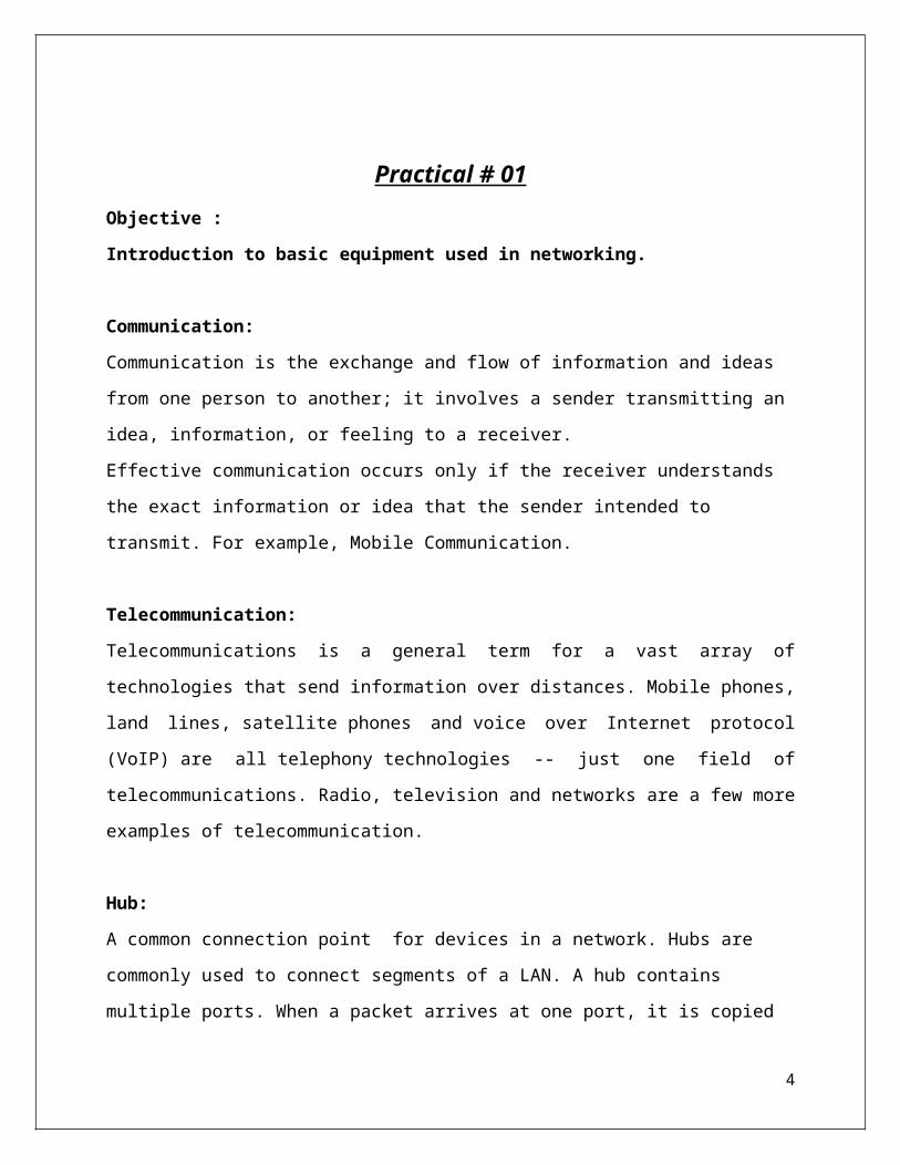
Router:
A router is used to interconnect multiple networks. Routers are more expensive than hubs and
switches.
Routers are completely different devices. Where a hub or switch is concerned with transmitting
frames, a router's job, as its name implies, is to route packets to other networks until that packet
ultimately reaches its destination. One of the key features of a packet is that it not only contains
data, but the destination address of where it's going.
4

A router is typically connected to at least two networks, commonly two Local Area Networks
(LANs) or Wide Area Networks (WAN) or a LAN and its ISP's network .
for example, your PC or workgroup and EarthLink. Routers are located at gateways, the places
where two or more networks connect. Using headers and forwarding tables, routers determine
the best path for forwarding the packets. Router use protocols such as ICMP to communicate
with each other and configure the best route between any two hosts.
5
QUESTIONS :
Explain the difference between Router and switch ?
_______________________________________________________________________
_______________________________________________________________________
_______________________________________________________________________
_______________________________________________________________________
_______________________________________________________________________
What is meant by ISP?
_______________________________________________________________________
_______________________________________________________________________
_______________________________________________________________________
What do you mean by ICMP?
_______________________________________________________________________
_______________________________________________________________________
_______________________________________________________________________
With the help of Diagrams, explain the difference in message communication methodology of
Router, switch and Hub?
_______________________________________________________________________
_______________________________________________________________________
_______________________________________________________________________
_______________________________________________________________________
6

Practical # 02
Objective :
A brief introduction to WAN and router.
Overview
A wide-area network (WAN) is a data communications network that connects user networks
over a large geographical area. WANs have several important characteristics that distinguish
them from LAN.
INTRODUCTION to WANs
A WAN is a data communications network that spans a large geographical area such as a state,
province, or country. WANs often use transmission facilities provided by common carrier such
as telephone companies.
These are major characteristics of WANs:
They connect devices that are separated by wide geographical areas.
They use serial connections of various types to access bandwidth over large geographic
areas.
Introduction to routers in a WAN
A router is a special type of computer. It has the same basic components as a standard desktop
PC. It has a CPU, memory, a system bus, and various input/output interfaces. However, routers
are designed to perform some very specific functions that are not typically performed by desktop
computers. For example, routers connect and allow communication between two networks and
determine the best path for data to travel through the connected networks.
Just as computers need operating systems to run software applications, routers need the
Internetwork Operating System (IOS) software to run configuration files. These configuration
files contain the instructions and parameters that control the flow of traffic in and out of the
routers. Routers use routing protocols to determine the best path for packets. The configuration
7

file specifies all the information for the correct setup and use of the selected, or enabled, routing
and routed protocols on a router.
The main internal components of the router are random-access memory (RAM), non-volatile
random-access memory (NVRAM), flash memory, read-only memory, and interfaces.
RAM has the following characteristics and functions
Stores routing tables
Holds fast-switching cache
Maintains packet-hold queues
Provides temporary memory for the configuration file of a router while the router is
powered on.
Loses content when a router is powered down or restarted.
NVRAM has the following characteristics and functions
Provides storage for the startup configuration file
Retains content when a router is powered down or restarted
Flash memory has the following characteristics and functions
Holds the IOS image
Allows software to be updated without removing and replacing chips on the processor
Retains content when a router is powered down or restarted
Can store multiple versions of IOS software
Is a type of electrically erasable programmable read-only memory(EEPROM)
ROM has the following characteristics and functions
Maintains instructions for power-on self test (POST) diagnostics
Stores basic operating system software
Requires replacing pluggable chips on the motherboard for software upgrades.
Interfaces have the following characteristics and functions
Connect routers to a network for packet entry and exit
Can be on the motherboard or on a separate module
8

The standards and protocols or primary functions of a WAN operate at the physical layer and at
the data link layer. This does not mean that the other five layers of the OSI model are not found
in a WAN. It simply means that the standards and protocols that define a WAN connection are
typically found at the physical and data link layers. In other words, the Layer 1 and Layer 2
WAN standards and protocols are different than the Layer 1 and Layer 2 LAN standards and
protocols.
The WAN physical layer describes the interface between the data terminal equipment (DTE) and
the data circuit-terminating equipment (DCE). Generally, the DCE is the service provider and the
DTE is the attached device.
The main function of a router is to transmit data using Layer 3 addresses. This process is also
called routing. Routing occurs at the network layer, which is layer 3. If a WAN operates at layers
1,2, and 3, is a router a LAN device or a WAN device? The answer is both, as is so often the case
in the field of networking. A router may be exclusively a LAN device. It may be exclusively a
WAN device, or it may sit at the boundary between a LAN and a WAN and be a LAN and WAN
device at the same time.
One of the roles of a router in a WAN is to route packets at Layer 3. But this is also a role of a
router in a LAN. Therefore routing is not strictly a WAN role of a router. When a router uses the
physical and data link layer standards and protocols that are associated with WANs, it is
operating as a WAN device. Therefore, the main role of a router in a WAN is not to route. It is to
provide connections between the various WAN physical and data-link standards.
9
Practical # 03
Objective :
Making straight-through and cross-over cable.
Straight-through cable
A straight through cable is used to connect two dissimilar devices e.g. workstations to hubs,
workstations to switches, servers to switches etc .
Straight-through cable is a type of twisted pair copper wire cable for local area network (LAN)
use for which the RJ-45 connectors at each end have the same pin out (i.e., arrangement of
conductors).
Straight-through cable is used to connect computers and other end-user devices (e.g., printers) to
networkig devices such as hubs and switches. It can also be used to directly connect like devices
(e.g., two hubs or two switches) if the cable is plugged into an uplink port on one (but not both)
of the devices.
Straight-through cables have identical terminations on each end.This is the typical method of
termination and unless otherwise specified, it is usually safe to assume that the cable is straight-
through. These cables are usually called patch cables illustrates as following
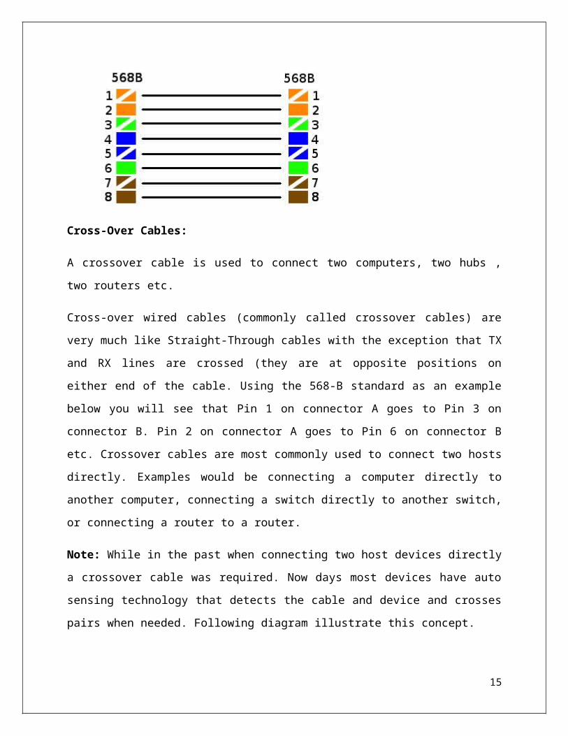
Cross-Over Cables:
A crossover cable is used to connect two computers, two hubs , two routers etc.
10

Cross-over wired cables (commonly called crossover cables) are very much like Straight-
Through cables with the exception that TX and RX lines are crossed (they are at opposite
positions on either end of the cable. Using the 568-B standard as an example below you will see
that Pin 1 on connector A goes to Pin 3 on connector B. Pin 2 on connector A goes to Pin 6 on
connector B etc. Crossover cables are most commonly used to connect two hosts directly.
Examples would be connecting a computer directly to another computer, connecting a switch
directly to another switch, or connecting a router to a router.
Note: While in the past when connecting two host devices directly a crossover cable was
required. Now days most devices have auto sensing technology that detects the cable and device
and crosses pairs when needed. Following diagram illustrate this concept.
ACTIVITY
Prepare your cable and get it graded by your teacher.
_______________________________________________________________________
Explain the difference between straight and cross cable and explain their uses.
_______________________________________________________________________
_______________________________________________________________________
_______________________________________________________________________
_______________________________________________________________________
11

Practical no 04
Objective:
To develop a star network topology
PREREQUISITES:
4 PCs A hub 4 Straight cables
DESCRIPTION
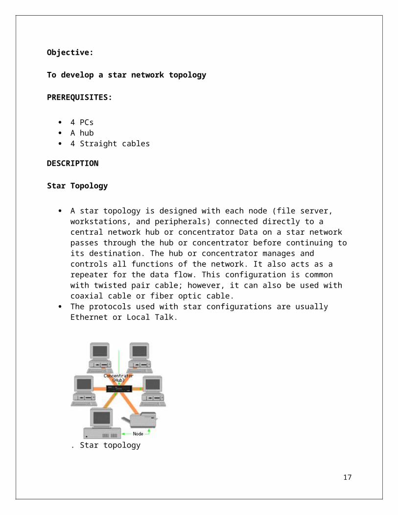
Star Topology
A star topology is designed with each node (file server, workstations, and peripherals) connected directly to a central network hub or concentrator Data on a star network passes through the hub or concentrator before continuing to its destination. The hub or concentrator manages and controls all functions of the network. It also acts as a repeater for the data flow. This configuration is common with twisted pair cable; however, it can also be used with coaxial cable or fiber optic cable.
The protocols used with star configurations are usually Ethernet or Local Talk.
. Star topology
Advantages of a Star Topology Easy to install and wire. No disruptions to the network when connecting or removing devices. Easy to detect faults and to remove parts.
12

Disadvantages of a Star Topology
Requires more cable length than a linear topology. If the hub or concentrator fails, nodes attached are disabled. More expensive than linear bus topologies because of the cost of the concentrators.
PROCEDURE:
Connect the PCs to hub using straight cables. Assign ip addresses to the pcs. Turn on file sharing on each pc and see whether they are accessible through other pcs or
not. You can use “ping” command to ensure accessibility. Names should be assigned to each pc in descriptive manner so that they can be identified
easily over the network Workgroup name should be same in all the nodes (PCs).
13

Practical no 05
Objective :
To get familiar with packet tracer and Cisco IOS.
Packet tracer
Packet Tracer is a protocol simulator developed at Cisco Systems. Packet Tracer (PT) is a
powerful and dynamic tool that displays the various protocols used in networking, in either Real
Time or Simulation mode. This includes layer 2 protocols such as Ethernet and PPP, layer 3
protocols such as IP, ICMP, and ARP, and layer 4 protocols such as TCP and UDP. Routing
protocols can also be traced. Packet Tracer is a supplement to and not a replacement for
experience with real equipment. Students are encouraged to compare the results obtained from
Packet Tracer network models with the behavior of real equipment.
Packet tracer tells us how two things communicate and are compatible. It is just a helping
module.
Creating a new topology in packet tracer.
Step 1 : Start packet tracer and enter simulation mode
14
Step 2 : Choosing devices and connections
Step 3 : Building the topology – Adding Hosts
Single click on the end devices
Single click on the generic host
Move the cursor into topology area. You will notice it turns into a plus “+” sign.
Single click in the topology area and it copies the device.
15

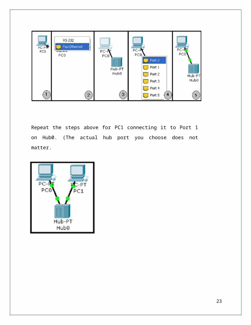
Step 4 : Adding a Hub
Select a hub, by clicking once on Hubs and once on a Generic hub.
Add the hub by moving the plus sign “+” below PC0 and PC1 and click once.
Connect PC0 to Hub0 by first choosing Connections.
Click once on the Copper Straight-through cable.
Perform the following steps to connect PC0 to Hub0:
1. Click once on PC0
2. Choose Fast Ethernet
3. Drag the cursor to Hub0
4. Click once on Hub0 and choose Port 0
5. Notice the green link lights on both the PC0 Ethernet NIC and the Hub0 Port 0 showing that
the link is active.
16
Repeat the steps above for PC1 connecting it to Port 1 on Hub0. (The actual hub
port you choose does not matter.
17

QUESTIONS
Why Fast ethernet is used instead of RS233?
_______________________________________________________________________
_______________________________________________________________________
_______________________________________________________________________
_______________________________________________________________________
What are different end devices available in software?
_______________________________________________________________________
_______________________________________________________________________
_______________________________________________________________________
_______________________________________________________________________
What does a green Link represents?
_______________________________________________________________________
_______________________________________________________________________
_______________________________________________________________________
_______________________________________________________________________
18
Practical # 06Objective
To get familiar with router configuration modes.
Command line interface basics
A command-line interface (CLI), also known as command-line user interface, console user
interface, and character user interface (CUI), is a means of interacting with a computer program
where the user (or client) issues commands to the program in the form of successive lines of text
(command lines).
Use the question mark (?) and arrow keys to help you enter commands:
• For a list of available commands, enter a question mark:
Router> ?
• To complete a command, enter a few known characters followed by a question mark
(with no space):
Router> s?
• For a list of command variables, enter the command followed by a space and a question
mark:
Router> show ?
• To re-display a command you previously entered, press the up arrow key. You can
continue to press the up arrow key for more commands.
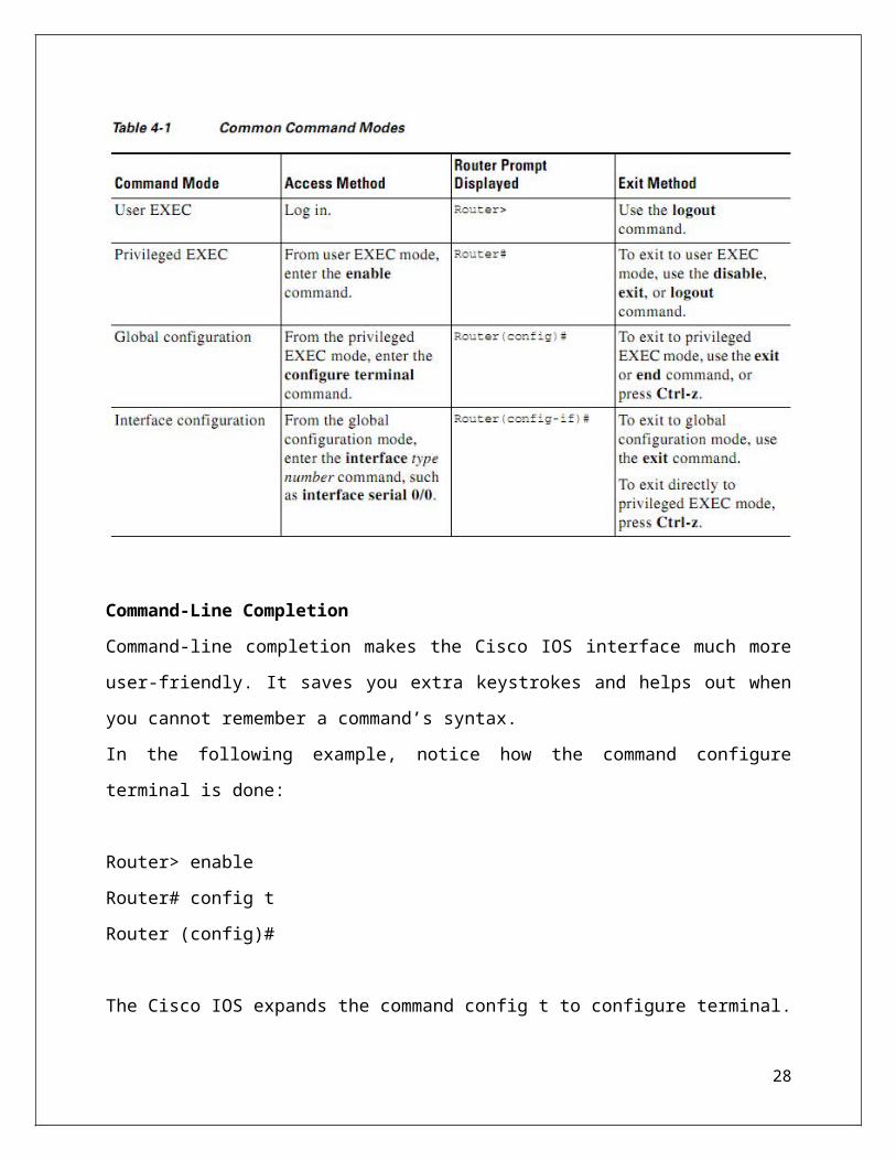
Understanding Command Modes
There are two primary modes of operation within the Cisco IOS: user EXEC mode and
privileged EXEC mode. When you first connect to the router, you are placed in the user EXEC
mode. The show commands in the user EXEC mode are limited to a few basic levels. You
cannot edit or view configurations at this stage; you can only view the router status and other
miscellaneous information. Editing the router’s configuration requires you to be in the privileged
EXEC mode. Use the enable command to enter this mode (see Table 4-1).
You can always tell whether you are in user EXEC mode or privileged EXEC mode by looking
at the router prompt being displayed. The user EXEC mode has a > at the end; the privileged
19

EXEC mode prompt always has a # at the end. In the privileged EXEC mode, the user interface
is further divided into different sub modes. Each command mode permits you to configure
different components on your router. The commands available at any given time depend on
which mode you are currently in. Entering a question mark (?) at the prompt displays a list of
commands available for each command mode (see Table 4-1).
Command-Line Completion
Command-line completion makes the Cisco IOS interface much more user-friendly. It saves you
extra keystrokes and helps out when you cannot remember a command’s syntax.
In the following example, notice how the command configure terminal is done:
Router> enable
Router# config t
Router (config)#
The Cisco IOS expands the command config t to configure terminal.
20

Another form of command-line completion is the use of the Tab key. If you start a command by
entering the first few characters, you can press the Tab key. As long as there is only one match,
the Cisco IOS will complete the command: for example, if you key in sh and press Tab, the
Cisco IOS completes the sh with show. If the Cisco IOS does not complete the command, you
can enter a few more letters and try again.
Undoing a Command or Feature
If you want to undo a command you entered or disable a feature, enter the keyword no before
most commands; for example, no ip routing
Saving Configuration Changes
You need to enter the copy running-config startup-config command to save your configuration
changes to nonvolatile random-access memory (NVRAM), so the changes are not lost if there is
a system reload or power outage.
For example:
Router# copy running-config startup-config
Building configuration...
It might take a minute or two to save the configuration to NVRAM. After the configuration has
been saved, the following appears:
[OK]
Router#
When you are in User Mode:
Router >
When you are in Privileged EXEC Mode:
Router #
The User mode of a router allows you to view the state of the router. But User mode does not
allow you to modify the router's configuration. But the Privileged EXEC mode allows you to
21

modify router's configuration. Without Privileged EXEC mode, you are unable to configure the
router's configuration.
To access the User mode, you don't need to type any command. After log-in, you are staying in
User mode. But to access Privileged EXEC Mode, you must have to type a command. The
command enable is used to access Privileged EXEC Mode.
QUESTIONS :
This command “copy running-config start-up config” will be copied to which part of the memory?
_______________________________________________________________________
_______________________________________________________________________
_______________________________________________________________________
What is virtual terminal? And how much virtual terminals you can configure with this command “line vty 0 4” through which you can connect the router with?
_______________________________________________________________________
_______________________________________________________________________
_______________________________________________________________________
22
Practical # 07
Objective :
Use cisco packet tracer software to configure the virtual port and also provide password
and user login.
Procedure :
Double click on cisco packet tracer, icon will be shown on your desktop.
This window appears after software launch.
23

Select generic router – PT.
Click on end devices and select end devices like pc.
Click on connections and select console.
Click on pc and connect to Rs 232 .Below in Figure
24

Click
on pc, this window appears and then click on desktop option
Click on terminal.
25

Press
ok
Type no and press enter
Type these commands
.
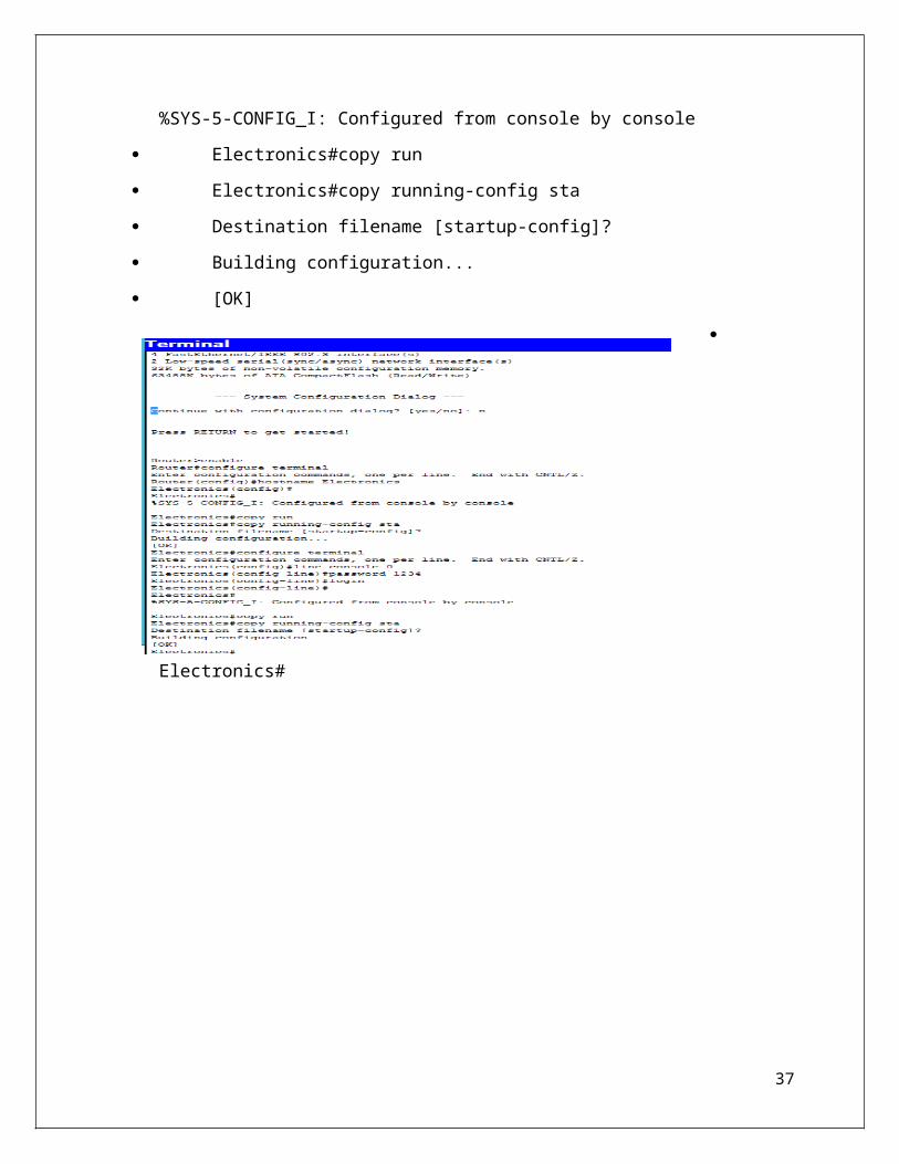
Press RETURN to get started!
Router>enable (press enter key)
Router#configure terminal (press enter key)
26

Enter configuration commands, one per line. End with CNTL/Z.
Router(config)#hostname Electronics (press enter key)
Electronics(config)# (press ctrl+c key)
Electronics#
%SYS-5-CONFIG_I: Configured from console by console
Electronics#copy run (press Tab key)
Electronics#copy running-config sta (press enter key)
Destination filename [startup-config]? (press enter key)
Building configuration...
[OK]
Electronics#configure terminal (press enter key)
Enter configuration commands, one per line. End with CNTL/Z.
Electronics(config)#line console 0 (press enter key)
Electronics(config-line)#password 1234 (press enter key)
Electronics(config-line)#login (press enter key)
Electronics(config-line)# (press ctrl+c key)
Electronics#
%SYS-5-CONFIG_I: Configured from console by console
Electronics#copy run
Electronics#copy running-config sta
Destination filename [startup-config]?
Building configuration...
[OK]
Electronics#
27
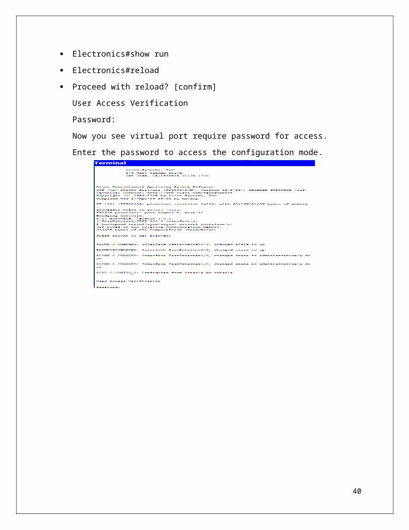
Electronics#reload
Proceed with reload? [confirm]
Electronics#reload
Proceed with reload? [confirm]
System Bootstrap, Version 12.1(3r)T2, RELEASE SOFTWARE (fc1)
Copyright (c) 2000 by cisco Systems, Inc.
PT 1001 (PTSC2005) processor (revision 0x200) with 60416K/5120K bytes of memory
Self decompressing the image :
##################################################################
######## [OK]
Press RETURN to get started!
%LINK-5-CHANGED: Interface FastEthernet0/0, changed state to up
%LINK-5-CHANGED: Interface FastEthernet1/0, changed state to up
%LINK-5-CHANGED: Interface FastEthernet0/0, changed state to
administratively down
%LINK-5-CHANGED: Interface FastEthernet1/0, changed state to
administratively down
%SYS-5-CONFIG_I: Configured from console by console
28

User Access Verification
Password:
Electronics>enable
Electronics#
Electronics#configure terminal
Enter configuration commands, one per line. End with CNTL/Z.
Electronics(config)#line vty 0 4
Electronics(config-line)#password cisco
Electronics(config-line)#login
Electronics(config-line)# (press ctrl+c key)
Electronics#
%SYS-5-CONFIG_I: Configured from console by console
Electronics#copy run (press tab key)
Electronics#copy running-config sta
Destination filename [startup-config]?
Building configuration...
[OK]
Electronics#show run
Electronics#reload
29

Proceed with reload? [confirm]
User Access Verification
Password:
Now you see virtual port require password for access.
Enter the password to access the configuration mode.
30

Practical # 08
Objective :
How to configure a virtual terminal access to router through TELNET.
Procedure:
Open Cisco Packet Tracer.
Select a router & two Pc’s.
Connect router and Pc-1 through Copper Cross Wire & 2nd pc through Console wire.
Figure:
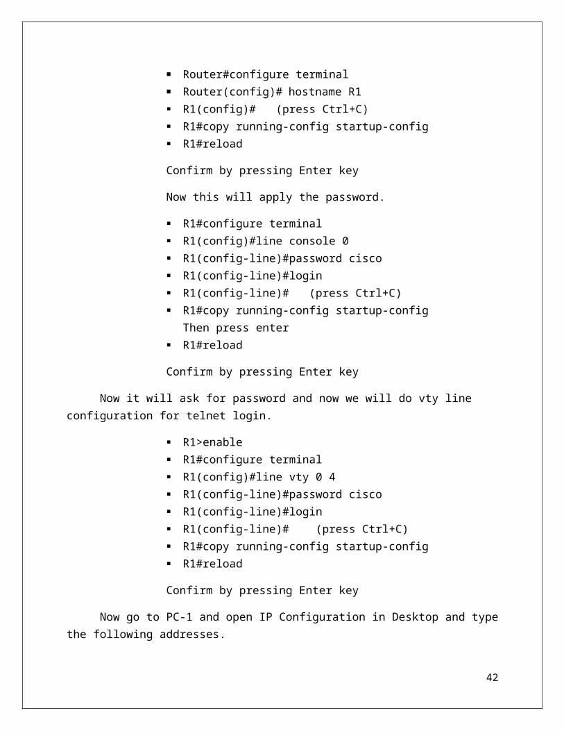
Go to PC’s terminal, and type the following commands Router>enable Router#configure terminal Router(config)# hostname R1 R1(config)# (press Ctrl+C) R1#copy running-config startup-config R1#reload
31

Confirm by pressing Enter key
Now this will apply the password.
R1#configure terminal R1(config)#line console 0 R1(config-line)#password cisco R1(config-line)#login R1(config-line)# (press Ctrl+C) R1#copy running-config startup-config
Then press enter R1#reload
Confirm by pressing Enter key
Now it will ask for password and now we will do vty line configuration for telnet login.
R1>enable R1#configure terminal R1(config)#line vty 0 4 R1(config-line)#password cisco R1(config-line)#login R1(config-line)# (press Ctrl+C) R1#copy running-config startup-config R1#reload
Confirm by pressing Enter key
Now go to PC-1 and open IP Configuration in Desktop and type the following addresses.
IP address 192.168.1.100
Subnet mask 255.255.255.0
Default gateway 192.168.1.1
Again open command line interface from router or terminal from PC-0.
R1>enable R1#configure terminal R1(config)#interface fastEthernet 0/0 R1(config-if)#ip address 192.168.1.1 255.255.255.0 R1(config-if)#no shutdown R1(config-if)# (press Ctrl+C) R1#copy run start
32

Go to PC-1 and open command prompt
telnet 192.168.1.1
It will ask for password, type cisco and you will get access to your router.
33

Practical no 09
Objective
How to apply encrypted password and message of the day (MOTD).
Procedure
Repeat same steps to connect router and a pc using a console connection.
Commands
For enabling password encryption.
For virtual terminal and console.
Banner
Password encryption
Engineer#No enable password
Engineer#Enable secret cisco (press enter)
Engineer# (press Ctrl+C)
Engineer#Copy run (press tab key)
Engineer#sta (enter key)
Engineer#exit
Type commands in pc terminal
For virtual terminal and console
34

Engineer#service password-encryption(press enter)
Banner
Engineer#configure terminal
Engineer(config)#banner ?
You see banner in configure mode type motd.
Motd (message of the day).
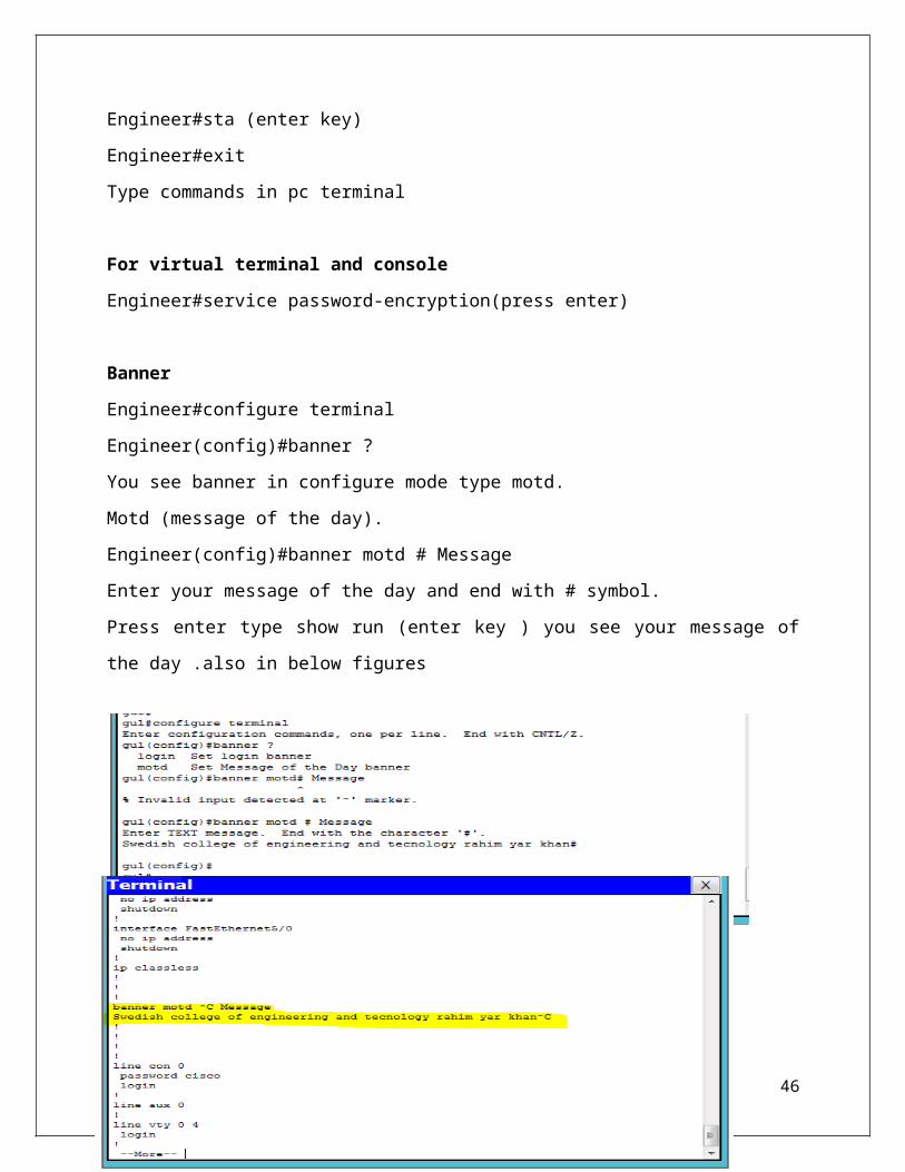
Engineer(config)#banner motd # Message
Enter your message of the day and end with # symbol.
Press enter type show run (enter key ) you see your message of the day .also in below figures
35

Practical no 10
Objective :
How to Make a LAN and how to apply DNS server to an IP address.
Procedure:
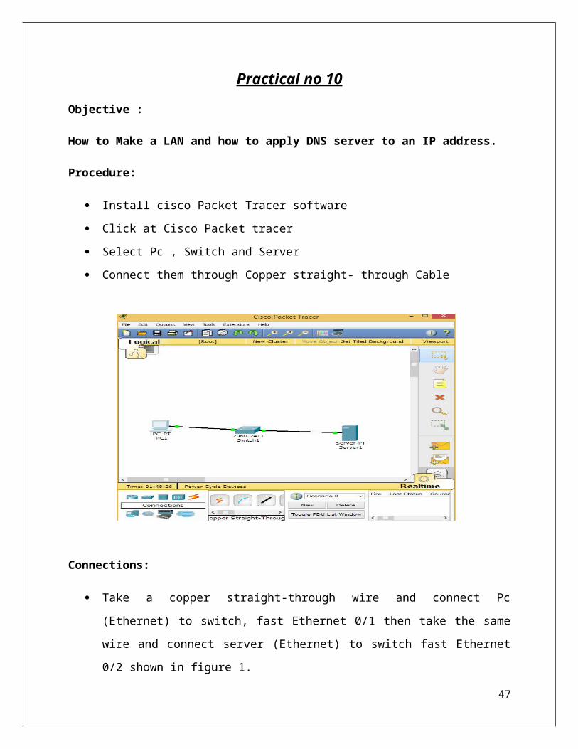
Install cisco Packet Tracer software
Click at Cisco Packet tracer
Select Pc , Switch and Server
Connect them through Copper straight- through Cable
Connections:
Take a copper straight-through wire and connect Pc (Ethernet) to switch, fast Ethernet 0/1
then take the same wire and connect server (Ethernet) to switch fast Ethernet 0/2 shown
in figure 1.
Give labels to Pc (192.168.1.100) & server (192.168.1.254).
Go to server, and click on config and write the ip address 192.168.1.254 and subnet mask
255.255.255.0
36
Go to PC, click on config and write the ip address 192.168.1.100 and subnet mask
255.255.255.0
Open Pc, then open command Prompt and type
Ping 192.168.1.254
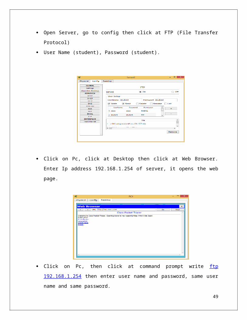
Open Server, go to config then click at FTP (File Transfer Protocol)
User Name (student), Password (student).
37

Click on Pc, click at Desktop then click at Web Browser. Enter Ip address 192.168.1.254
of server, it opens the web page.
Click on Pc, then click at command prompt write ftp 192.168.1.254 then enter user name
and password, same user name and same password.
38

Now take a wireless router, connect it through straight-through cable to Ethernet.
Click at Router
Click on config, then click on LAN and after that set ip address 192.168.1.1
Click on server, open config and set gateway 192.168.1.1.
Click HTTP and edit packet tracer with superyahoo.com. Just edit it.
39
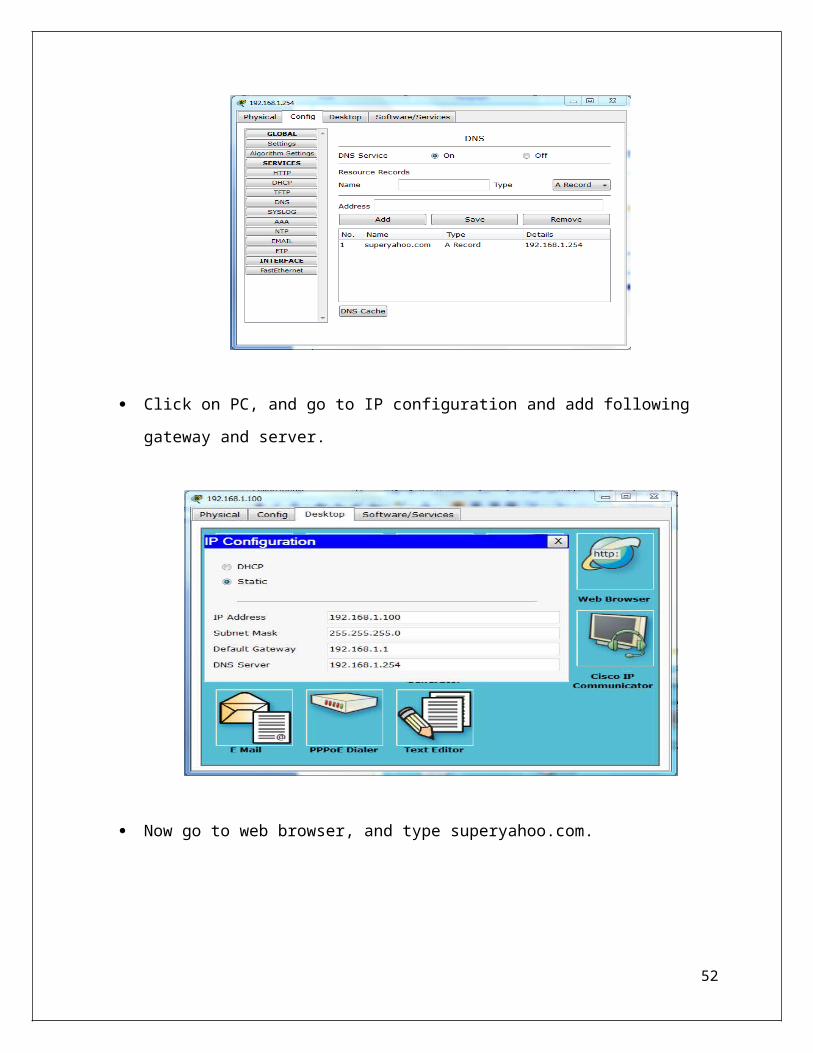
Click on server, click at config then open settings and set Gateway address 192.168.1.1.
Then click on HTTP and write welcome to superyahoo.com.
DNS server, turn it off then write name supperyahoo.com and give address
192.168.1.254. Click on ADD and again turn it on.
Click on PC, and go to IP configuration and add following gateway and server.
Now go to web browser, and type superyahoo.com.
40

QUESTIONS
What is LAN?
_______________________________________________________________________
_______________________________________________________________________
_______________________________________________________________________
_______________________________________________________________________
What are different connections links available to connect routers and end devices?
_______________________________________________________________________
_______________________________________________________________________
_______________________________________________________________________
_______________________________________________________________________
What happens when you write superyahoo.com on web browser, paste the output which came on your screen?
_______________________________________________________________________
_______________________________________________________________________
41
Practical no 11
Objective :
Getting started with wireshark.
One’s understanding of network protocols can often be greatly deepened by “seeing protocols in
action” and by “playing around with protocols” – observing the sequence of messages
exchanged between two protocol entities, delving down into the details of protocol operation,
and causing protocols to perform certain actions and then observing these actions and their
consequences. This can be done in simulated scenarios or in a “real” network environment such
as the Internet.
The Java applets that accompany this text take the first approach. In these Wireshark labs. You’ll
be running various network applications in different scenarios using a computer on your desk, at
home, or in a lab. You’ll observe the network protocols in your computer “in action,” interacting
and exchanging messages with protocol entities executing elsewhere in the Internet. Thus, you
and your computer will be an integral part of these “live” labs. You’ll observe, and you’ll learn,
by doing. The basic tool for observing the messages exchanged between executing protocol
entities is called a packet sniffer. As the name suggests, a packet sniffer captures (“sniffs”)
messages being sent/received from/by your computer; it will also typically store and/or display
the contents of the various protocol fields in these captured messages. A packet sniffer itself is
passive. It observes messages being sent and received by applications and protocols running on
your computer, but never sends packets itself. Similarly, received packets are never explicitly
addressed to the packet sniffer. Instead, a packet sniffer receives a copy of packets that are
sent/received from/by application and protocols executing on your machine.
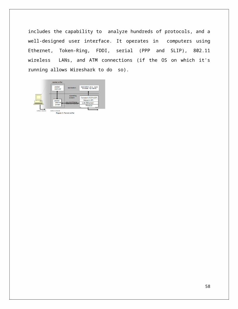
Figure 1 shows the structure of a packet sniffer. At the right of Figure 1 are the protocols (in this
case, Internet protocols) and applications (such as a web browser or ftp client) that normally run
on your computer. The packet sniffer, shown within the dashed rectangle in Figure 1 is an
addition to the usual software in your computer, and consists of two parts. The packet capture
library receives a copy of every link-layer frame that is sent from or received by your
computer. Recall from the discussion from section 1.5 in the text (Figure 1.202) that messages
exchanged by higher layer protocols such as HTTP, FTP, TCP, UDP, DNS, or IP all are
42

eventually encapsulated in link-layer frames that are transmitted over physical media such as an
Ethernet cable. In Figure 1, the assumed physical media is an Ethernet, and so all upper layer
protocols are eventually encapsulated within an Ethernet frame. Capturing all link-layer frames
thus gives you all messages sent/received from/by all protocols and applications executing in
your computer. The second component of a packet sniffer is the packet analyzer, which displays
the contents of all fields within a protocol message. In order to do so, the packet analyzer must
“understand” the structure of all messages exchanged by protocols. For example, suppose we are
interested in displaying the various fields in messages exchanged by the HTTP protocol in
Figure 1. The packet analyzer understands the format of Ethernet frames, and so can identify the
IP datagram within an Ethernet frame. It also understands the IP datagram format, so that it can
extract the TCP segment within the IP datagram. Finally, it understands the TCP segment
structure, so it can extract the HTTP message contained in the TCP segment. Finally, it
understands the HTTP protocol and so, for example, knows that the first bytes of an HTTP
message will contain the string “GET,” “POST,” or “HEAD,” as shown in Figure 2.8 in the text
We will be using the Wireshark packet sniffer [http://www.wireshark.org/] for these labs,
allowing us to display the contents of messages being sent/received from/by protocols at
different levels of the protocol stack. (Technically speaking, Wireshark is a packet analyzer
that uses a packet capture library in your computer). Wireshark is a free network protocol
analyzer that runs on Windows, Linux/Unix, and Mac computers. It’s an ideal packet analyzer
for our labs – it is stable, has a large user base and well-documented support that includes a
user-guide (http://www.wireshark.org/docs/wsug_html_chunked/), man pages
(http://www.wireshark.org/docs/man-pages/), and a detailed FAQ
(http://www.wireshark.org/faq.html), rich functionality that includes the capability to analyze
hundreds of protocols, and a well-designed user interface. It operates in computers using
Ethernet, Token-Ring, FDDI, serial (PPP and SLIP), 802.11 wireless LANs, and ATM
connections (if the OS on which it's running allows Wireshark to do so).
43

44

Getting Wireshark
In order to run Wireshark, you will need to have access to a computer that supports both
Wireshark and the libpcap or WinPCap packet capture library. The libpcap software will be
installed for you, if it is not installed within your operating system, when you install Wireshark.
See http://www.wireshark.org/download.html for a list of supported operating systems and
download sites Download and install the Wireshark software:
Go to http://www.wireshark.org/download.html and download and install the Wireshark
binary for your computer.
Download the Wireshark user guide.
The Wireshark FAQ has a number of helpful hints and interesting tidbits of information,
particularly if you have trouble installing or running Wireshark. When you run the Wireshark
program, the Wireshark graphical user interface shown in Figure 2 will displayed. Initially, no
45
data will be displayed in the various windows structure
Running Wireshark
The Wireshark interface has five major components:
1. The command menus are standard pulldown menus located at the top of the window. Of
interest to us now are the File and Capture menus. The File menu allows you to save captured
packet data or open a file containing previously captured packet data, and exit the Wireshark
application. The Capture menu allows you to begin packet capture.
2. The packet-listing window displays a one-line summary for each packet captured, including
the packet number (assigned by Wireshark; this is not a packet number contained in any
protocol’s header), the time at which the packet was captured, the packet’s source and
destination addresses, the protocol type, and protocol-specific information contained in the
packet. The packet listing can be sorted according to any of these categories by clicking on a
46
column name. The protocol type field lists the highest level protocol that sent or received this
packet, i.e., the protocol that is the source or ultimate sink for this packet.
3. The packet-header details window provides details about the packet selected highlighted) in
the packet listing window. (To select a packet in the packet listing window, place the cursor
over the packet’s one-line summary in the packet listing window and click with the left mouse
button.). These details include information about the Ethernet frame (assuming the packet was
sent/receiverd over an Ethernet interface) and IP datagram that contains this packet. The
amount of Ethernet and IP-layer detail displayed can be expanded or minimized by clicking on
the plus-or-minus boxes to the left of the Ethernet frame or IP datagram line in the packet
details window. If the packet has been carried over TCP or UDP, TCP or UDP details will also
be displayed, which can similarly be expanded or minimized. Finally, details about the highest
level protocol that sent or received this packet are also provided.
4. The packet-contents window displays the entire contents of the captured frame, in both ASCII
and hexadecimal format.
5. Towards the top of the Wireshark graphical user interface, is the packet display filter field,
into which a protocol name or other information can be entered in order to filter the information
displayed in the packet-listing window (and hence the packet-header and packet-contents
windows). In the example below, we’ll use the packet-display filter field to have Wireshark hide
(not display) packets except those that correspond to HTTP messages.
Taking Wireshark for a Test Run
The best way to learn about any new piece of software is to try it out! We’ll assume that your
computer is connected to the Internet via a wired Ethernet interface. Do the following
1. Start up your favorite web browser, which will display your selected homepage.
2. Start up the Wireshark software. You will initially see a window similar to that shown in
Figure 2, except that no packet data will be displayed in the packet-listing, packet-header, or
packet-contents window, since Wireshark has not yet begun capturing packets.
47

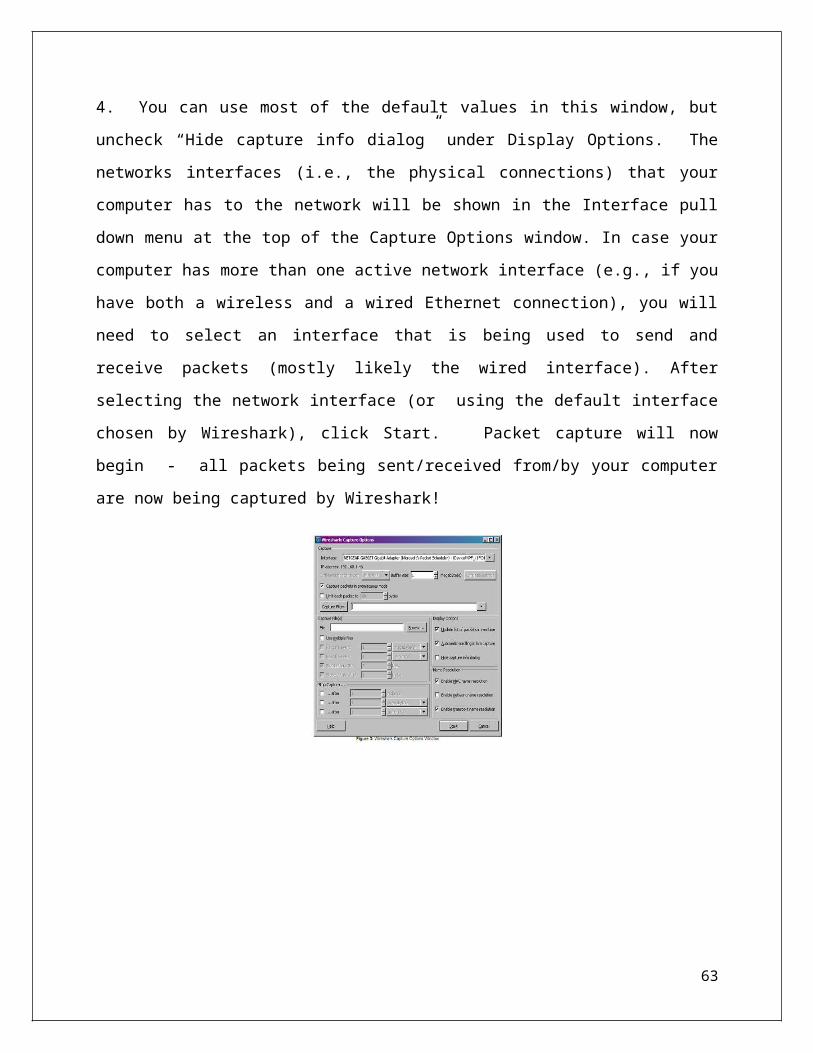
3. To begin packet capture, select the Capture pull down menu and select Options. This will
cause the “Wireshark: Capture Options” window to be displayed, as shown in Figure 3.
4. You can use most of the default values in this window, but uncheck “Hide capture info
dialog” under Display Options. The networks interfaces (i.e., the physical connections) that your
computer has to the network will be shown in the Interface pull down menu at the top of the
Capture Options window. In case your computer has more than one active network interface
(e.g., if you have both a wireless and a wired Ethernet connection), you will need to select an
interface that is being used to send and receive packets (mostly likely the wired interface). After
selecting the network interface (or using the default interface chosen by Wireshark), click Start.
Packet capture will now begin - all packets being sent/received from/by your computer are now
being captured by Wireshark!
48
5. Once you begin packet capture, a packet capture summary window will appear, as shown in
Figure 4. This window summarizes the number of packets of various types that are being
captured, and (importantly!) contains the Stop button that will allow you to stop packet capture.
Don’t stop packet capture yet.
6. While Wireshark is running, enter the URL: http://gaia.cs.umass.edu/wireshark-labs/INTRO-
wireshark-file1.html and have that page displayed in your browser. In order to display this
page, your browser will contact the HTTP server at gaia.cs.umass.edu and exchange HTTP
messages with the server in order to download this page, as discussed in section 2.2 of the text.
The Ethernet frames containing these HTTP messages will be captured by Wireshark .
7. After your browser has displayed the INTRO-wireshark-file1.html page, stop Wireshark
packet capture by selecting stop in the Wireshark capture window. This will cause the
Wireshark capture window to disappear and the main Wireshark window to display all packets
captured since you began packet capture. The main Wireshark window should now look similar
to Figure 2. You now have live packet data that contains all protocol messages exchanged
between your computer and other network entities! The HTTP message exchanges with the
gaia.cs.umass.edu web server should appear somewhere in the listing of packets captured. But
there will be many other types of packets displayed as well (see, e.g., the many different protocol
types shown in the Protocol column in Figure 2). Even though the only action you took was to
download a web page, there were evidently many other protocols running on your computer that
49

are unseen by the user. We’ll learn much more about these protocols as we progress through
the text! For now, you should just be aware that there is often much more going on than “meet’s
the eye”!
8. Type in “http” (without the quotes, and in lower case – all protocol names are in lower case
in Wireshark) into the display filter specification window at the top of the main Wireshark
window. Then select Apply (to the right of where you entered “http”). This will cause only
HTTP message to be displayed in the packet-listing window.
9. Select the first http message shown in the packet-listing window. This should be the HTTP
GET message that was sent from your computer to the gaia.cs.umass.edu HTTP server. When
you select the HTTP GET message, the Ethernetframe, IP datagram, TCP segment, and HTTP
message header information will be displayed in the packet-header window3. By clicking plus-
and-minus boxes to the left side of the packet details window, minimize the amount of Frame,
50

Ethernet, Internet Protocol, and Transmission Control Protocol information displayed. Maximize
the amount information displayed about the HTTP protocol. Your Wireshark display should
now look roughly as shown in Figure 5. (Note, in particular, the minimized amount of protocol
information for all protocols except HTTP, and the maximized amount of protocol information
for HTTP in the packet-header window).
10. Exit Wireshark
51
Practical no 12
Objective :
Wireshark Activities
This lab requires connection to an HTTP server.
1. Open any website using your internet browser e.g. http://www.microsoft.com
2. Start Wireshark and monitor the network traffic for 3 minutes. If possible, perform some
WWW activity with a remote site.
3. Using Wireshark, determine the percentages of traffic for different protocols:
TCP: __________________ %
UDP: _________________ %
ARP: _________________ %
ICMP: _________________ %
IPX: __________________ %
NetBIOS: __________________ %
4. Using Wireshark, determine the MAC address of three computers:
Your own MAC address:
_______________________________________________________________
Your own IP address:
_______________________________________________________________
Host 1 (MAC):
_______________________________________________________________
Host 1 (IP):
_______________________________________________________________
52

Host 2 (MAC):
____________________________________________________________
Host 2 (IP):
________________________________________________________________
5. Start a WWW browser session for a remote site (such as www.intel.com), and outline the
traffic for the connection:
Source IP:
_______________________________________________________________________
Destination IP:
_______________________________________________________________________
Source Port:
_______________________________________________________________________
Destination Port:
_______________________________________________________________________
DNS Address:
_______________________________________________________________________
6. From the run of Wireshark, outline the usage of the ARP protocol:
_______________________________________________________________________
_______________________________________________________________________
_______________________________________________________________________
_______________________________________________________________________
53

Practical no 13
Objective
Introduction to TP-Link Devices
TL-WR740N
150Mbps Wireless N Router
Overview
The TL-WR740N is a simple and secure way to share your high-speed Internet connection at Wireless-N speeds for surfing the Internet, email or online chat. The wireless N Router is 802.11b & g compatible and gives users 802.11n performance up to 150Mbps at a remarkably affordable price. Bordering on 11n and surpassing 11g speed enables bandwidth-intensive applications such as video streaming. Users can enjoy a high quality experience when video streaming, using VoIP, or gaming online wirelessly, not previously practical with 11g devices.
Features
Wireless speed up to 150Mbps Easy wireless security encryption at a push of the WPS button Supports Multiple SSIDs to separate different users within the same wireless network WDS Wireless Bridge provides seamless bridging to expand the wireless network IP based Bandwidth Control allows administrators to determine how much bandwidth is
allotted to each PC Live Parental Controls allow parents or administrators to establish restricted access
policies for children or staff
54

Specifications
Hardware Features
Wireless Features
IP QOS -- Manage your Bandwidth
Within the wireless network, indiscriminate Internet surfing and bandwidth-guzzling downloads by internal users often leave homes or small offices with insufficient bandwidth. TL-WR720N supports an IP QOS function, allowing optimum utilization of bandwidth and offering bandwidth control over congestion, preventing bandwidth abuse. In this way, users of a small network receive committed and specific bandwidth, preventing non-critical applications from degrading network performance.
55

TL-WR841N
300Mbps Wireless N Router
Overview
300Mbps Wireless N Router TL-WR841N is a combined wired/wireless network connection device designed specifically for small business and home office networking requirements. TL-WR841N’s exceptional and advanced wireless performance make it ideal for streaming HD video, making VoIP and online gaming. Also, WPS button on the sleek and fashionable exterior ensures WPA2 encryptions, preventing the network from outside intrusions.
Features
Wireless N speed up to 300Mbps makes it ideal for bandwidth consuming or interruption sensitive applications like video streaming, online gaming and VoIP
Easily setup a WPA encrypted secure connection at a push of the WPS button WDS wireless bridge provides seamless bridging to expand your wireless network QoS function assures the quality of VoIP and multimedia streaming Wi-Fi On/Off Button allows users to simply turn their wireless radio on or off Features parental control function managing the internet access of children or
employee’s computer Supports virtual server, special application and DMZ host ideal for creating a website
within your LAN Offers Auto-mail function for system log, convenient for managing the router Backward compatible with 802.11b/g products Easy Setup Assistant provides quick & hassle free installation Sleek exterior, can be mounted on a wall or placed horizontally on a table or desk
56

Specifications
Hardware Features
Wireless Features
57
IP QoS-Control Bandwidth ReasonablyAmong the wireless network, indiscriminate Internet surfing and bandwidth-guzzling downloads by internal users often leave home or small office with insufficient bandwidth. TL-WR841N supports IP QoS function, allowing optimum utilization of bandwidth and offers bandwidth control over congestion, preventing the bandwidth abuse. In this way, the users of a small network receive committed and specific bandwidth, preventing non-critical applications from degrading network performance.
Practical no 13
Objective
Detail Study About TP-Link Devices
TL-MR3420
3G/4G Wireless N Router
Overview
Share the freedom of 3G/4G! The TL-MR3420 3G/4G Wireless N Router allows users to share a 3G/4G mobile broadband connection with family and friends via wired or wireless connections. By connecting a 3G/4G USB modem to the routers, a Wi-Fi hotspot is instantly established, via which multiple devices can access the Internet and share data and applications wirelessly.
Features
Blazing 4G speeds and backward compatible with 3G modems 3G/4G and WAN failover guarantees an ‘always-online’ Internet connection Wireless N speed up to 300Mbps for a robust Wi-Fi network Supports PPPoE, Dynamic IP, Static IP, PPTP, L2TP Cable Internet Access
58

Supports 64/128-bit WEP, WPA/WPA2 and WPA-PSK/WPA2-PSK encryption Wireless security encryption easily at the push of the WPS button WDS wireless bridge provides seamless bridging to expand your wireless network IP based bandwidth control allows administrators to determine how much bandwidth is allotted
to each PC Parental Control allows parents or administrators to establish restricted access policies for
children or staff
Specifications
Hardware Features
Wireless Features
Wireless N Speed & RangeComplying with the IEEE 802.11n standard, the TL-MR3420 can establish a wireless network with transmission speeds of up to 300Mbps, while mitigating data loss over long distances and through
59

obstacles in a small office or a large apartment, even in a steel-and-concrete building. Above all, users can easily pick up their wireless network's signal at longer distances from the router, where with legacy 11g products they would have to be much closer.
Practical no 14
Objective
54Mbps High Power Wireless Access Point (TL-WA5110G)
Overview
The TL-WA5110G High Power Wireless Access Point is dedicated to Small Office/Home Office (SOHO) and long distance wireless network solutions. It integrates the functions of a Wireless Access Point, WISP Client, Firewall, and Router.The High Power Wireless Access Point features high output power and high RX sensitivity can significantly extend the transmission range to reduce dead spots and to deliver a more stable wireless connection. Also supports distance control from 0km to 52.6km, which breaks through distance limitations in normal 802.11g devices, enables ultra-long distance wireless transmission.
Features
Supports AP Client Router, AP Router and AP operation mode High output transmission power and reception sensitivity optimized Supports WISP Mode (PPPoE client on wireless interface) Supports Passive Power over Ethernet
60

Supports Wireless Distribution System (WDS) Distance Adjustment for long range transmission Supports Antenna Alignment Supports Layer 2 User Isolation Provides throughput monitor indicating the current wireless throughput Supports Ping Watch Dog Supports Link Speed Test Supports Remote Management Supports PPPoE, Dynamic IP, Static IP Internet Access Built-in NAT and DHCP server supporting Address Reservation
Specifications
Hardware Features
61

Wireless Features
Multiple Operation ModesThe TL-WA5110G provides three operation modes for multiple users to access the Internet: AP client router, AP router and AP. In AP client router mode, it works as a WISP CPE. In AP router mode, it can access the Internet via an ADSL/Cable Modem. In AP mode it can work in various modes, such as Access Point/Client/WDS Bridge/Repeater.
62
Practical no 15
Objective
TP-Link Antennas
TL-ANT2415D
2.4GHz 15dBi Outdoor Omni-directional Antenna
Overview
Outdoor omni-directional antenna TL-ANT2415D operates in the 2.4-2.5 GHz band and provides 15dBi omni-directional operation, which largely extends the wireless range and delivers much better wireless performance. The antenna offers the N female connector guaranteeing wider compatibility with most of the wireless equipments. Also, the weather proof design ensures that it can work normally for various demanding outdoor solutions. The Outdoor Omni-Directional Antenna emits a powerful amplified signal over a 360 degree radius, delivering a strong multidirection signal from an Access Point or a Bridge. If you have multiple locations or buildings where you would like to integrate your wireless network, simply place the TL-ANT2415D in between the buildings with your Acess Point. It is most effective when placed at the top of buildings.
Features
Provides 15dBi signal gain Provides N Female connector Be applied to various weather conditions Compatible with all the 802.11n/b/g products (2.4GHz)
63

Specifications
Easy To UseInstallation of the TL-ANT2415D is simple and straight forward. It is compatible with most wireless devices (Access Points, Routers, Bridges and Network Adapters) on the market with removable external antennas.
64

TL-ANT2408CL
2.4GHz 8dBi Indoor Omni-directional Antenna
Overview
Indoor omni-directional antenna TL-ANT2408CL operates in the 2.4-2.5 GHz band and provides 8dBi omni-directional operation, which largely extends the wireless range and delivers much better wireless performance. The antenna offers the RP-SMA Female connector guaranteeing wider compatibility with most of the wireless equipments.
Replacing your wifi antenna with TL-ANT2408CL will significantly increase the range and strength of your wifi signal. This quality built omni-directional antenna is a direct replacement for the antenna that comes standard with your router, access point. Because it is omni-directional, no aiming is equired - it can send and receive wifi in all directions.
Features
Compliant with 802.11n/b/g (2.4GHz) 8dBi signal gain RP-SMA Female connector
65

Specification
Easy To UseInstallation is very easy - just detach your device's factory antenna and attach our booster antenna and you'll experience an instant increase in signal coverage and stability. Please note that the increase in signal strength depends mostly on your router or adapter; upgrading the antennas helps but the signal cannot transmit or receive at a level that your modem or adapter does not have.
66