
swedishcr.weebly.com · Web viewDEPARTMENT OF ELECTRONIC ENGINEERING, SCE&T, RAHIM’YAR’KHAN...
29
DEPARTMENT OF ELECTRONIC ENGINEERING, SCE&T, RAHIM’YAR’KHAN INDUSTRIAL ELECTRONICS (8 TH SEMESTER, FINAL YEAR) EXPERIMENT # 1/16 Name: ________________________________________Roll No: _____________________ Score: ______________Signature of the Lab Tutor: __________________Date: ____________ ------------------------------------------------------------------------------ ---------------------------------------------- GETTING FAMILIAR WITH PLC & STEP 7- MICRO/WIN 32AND THE S7-200 PLC OBJECTIVE Upon successful completion of this lab the students will be able to Understand the programming procedures and its industrial values. To construct PLC programs in LAD using Siemens Step 7-Micro/Win 32. To run and debug the programs on S7-200 PLC. REFERENCE John.W.Webb.Ronald A.Reis,”programmable logic controllers”. Introduction: Early machines were controlled by mechanical means using cams, gears, levers, and other basic mechanical devices. As the complexity grew, so did the need for a more sophisticated control system. This system contained wired relay and switch control elements. These elements were
Transcript of swedishcr.weebly.com · Web viewDEPARTMENT OF ELECTRONIC ENGINEERING, SCE&T, RAHIM’YAR’KHAN...

DEPARTMENT OF ELECTRONIC ENGINEERING, SCE&T, RAHIM’YAR’KHAN
INDUSTRIAL ELECTRONICS (8TH SEMESTER, FINAL YEAR) EXPERIMENT # 1/16
Name: ________________________________________Roll No: _____________________
Score: ______________Signature of the Lab Tutor: __________________Date: ____________
----------------------------------------------------------------------------------------------------------------------------
GETTING FAMILIAR WITH PLC & STEP 7- MICRO/WIN 32AND THE
S7-200 PLC
OBJECTIVE
Upon successful completion of this lab the students will be able to
Understand the programming procedures and its industrial values.
To construct PLC programs in LAD using Siemens Step 7-Micro/Win 32.
To run and debug the programs on S7-200 PLC.
REFERENCE
John.W.Webb.Ronald A.Reis,”programmable logic controllers”.
Introduction:
Early machines were controlled by mechanical means using cams, gears, levers, and other basic
mechanical devices. As the complexity grew, so did the need for a more sophisticated control system.
This system contained wired relay and switch control elements. These elements were wired as required to
provide the control logic necessary for the particular type of machine operation, this was acceptable for a
machine that never needed to be changed or modified, but as manufacturing techniques improved and
plant changeover to new products became more desirable and necessary, a more versatile means of
controlling this equipment had to be developed . Hardwired relay and switch logic was cumbersome and
time consuming to modify. Wiring had to be removed and replaced to provide for the new control
scheme. This modification was difficult and time consuming to design and install and any “bug” in the
design could be a major problem to correct since it also required rewiring of the system . A new means to
modify control circuitry was needed. The development and testing ground for this new means was the
U.S. auto industry. The time period was the late 1960’s and early 1970’s and the result was the
programmable logic controllers, or PLC. Automotive plants were confronted with a change in

manufacturing techniques every time a model change and PLC has at first gradually , in some cases, for
changes on the same model if improvements had to be made during the model year. The PLC provided an
easy way of program the wiring rather than actually rewiring the control system.
The PLC that was developed during this time was not easy to program. The language was
cumbersome to write, requiring highly trained programmers. These early devices were merely relay
replacements and could do very little else. The PLC has at first gradually,, and in recent years rapidly,
developed into a sophisticated and highly versatile control system components. Units today are capable of
performing complex math functions including numerical integration and differentiation and operate at the
fast microprocessor speeds now available.
Over ALL PLC system
The PLC system consist of four major units and they are interconnected.
1. Central Processing Unit(CPU).The “brain” of the system, which has three subparts
a. Microprocessor. The computer center that carries out mathematics and logic operations.
b. Memory. The area of CPU in which data and information is stored or retrieved .Holds the system
software and user program.
c. Power Supply: The electrical supply that converts alternating (AC) line voltage to various
operational DC values. In the process, the power supply filters and regulate the DC voltages to
ensure proper computer operation.
2. I/O Modules: the input has terminal into which outside process electrical signals, generated by
sensors or transducers, are entered. The output module has terminals to which output signals are sent
to activate relays, solenoids, various slid-state switching devices, motors, and display, an electronic
system for connecting I/O modules to remote locations can be added if needed. The an/actual
operating process under OPLC control can be thousand odd feet from the CPU and its I/O modules.
3. Programmer/Monitor: the programmer/monitor(PM) is a device used to communicate with the
circuits of the PLC. Hand Held terminals, industrial terminals, and the personal computer exist as PM
devices. In a hand held unit input takes through a membrane keypad and the display (LCD) . With the
industrial terminal or personal computer, more complex, typewriter type keyboards and cathode ray
tubes (CRTs) are employed.

4. Racks & Chassis: The racks on which the PLC parts are mounted & the enclosures on which
the CPU, PM & I/O modules are mounted.
PLC Advantages:
Following are the 13 major advantages of using a PLC.
Flexibility
Implementing changes & correcting errors
Large quantities of contacts
Lower cost
Pilot running
Visual observation
Speed of operation
Ladder or Boolean Programming methods
Reliability & maintainability
Simplicity of Control System components
Documentation

Security
Ease of changes by Reprogramming
Newer technology
Fixed program applications
Environmental considerations
Fail-safe operations
Simatic S7-200
Controllers may consist of logical components and connections among them. Depending on the
current logical value of input, output is produced to change the status of the system. PLC may realize
such controllers. Today, the command and feedback control systems of industrial automation systems are
realized by programmable logic controllers (PLCs). Siemens Simatic S7-200 is one of the PLC brands
widely used in industry.
In order for PLCs to work as controllers, they mustbe able to realize some functions. These functions are
basic and combinational logic operations such as AND, OR, AND-NOT, OR-NOT, timer and
counter operations. In addition to these, PLCs may have the ability to realize several transfer,
mathematical, and PID operations.PLC consists of three main parts: CPU, memory and I/O units. CPU is
the brain of PLC. It reads the input values from inputs, runs the program existed in the program memory
and writes the output values to the output register. Memory is used to store different types ofinformation
in the binary structure form. The memory range of S7-200 is composed of three main parts as program,
parameter, and retentive data fields. I/O units provide communication between PLC control
systems.
Constructing of PLC Program
There are mainly two methods for composing PLC programs: Ladder Logic Diagram (LAD) and
Statement List(STL).
LAD method is commonly used to implement the programs for process controls. A network of LAD is a
row of connected elements that form a complete circuit between the left anright power rail.
The left power rail represents the energized conductor whereas the right power rail represents the return
path conductor of the circuit.
Power flows from the left rail, through the closed contacts to the coils or boxes connected to the right
power rail.
You can then use the power flow to activate the outputs according to your program. Step 7-Micro/Win 32
is user-friendly development environment for S7-200. A screen shot of Step 7-Micro/Win 32 is shown in
Figure 1.1.
Figure 1.1 Step 7-Micro/Win 32
A simple LAD realizing some Boolean operations is given below:

Figure 1.2 Sample LAD for Boolean operations.
You can also switch between LAD and STL by selecting Ladder or STL from View menu. By this way,
you can see how LAD and STL relate to each other.
Figure 1.3STL codes for the LAD in Figure 1.2
In STEP 7-Micro/WIN 32, click on New option in the Project menu for new project. After composing
program, click the Compile button on the taskbar. By clicking this button, software translates the
program code block into machine language for execution by the CPU. A program can not be

downloaded to the CPU until it is compiled. If there is an error in your program, your program will not be
compiled and software will warn you about the errors in your program. After correcting errors, try to
compile again.
You can save your work by clicking Save All option in the Project menu. You can also load existed
projects by clicking Open option in the Project menu.
Running PLC Programs
When the program is compiled successfully, click on the Download button on the taskbar to transfer the
compiled program to the PLC. During this operation, be sure that PLC is STOP or TERM mode. When
the transfer is completed, switch the PLC to RUN mode or click RUN button in the
toolbar .Now, PLC is running. Switch the inputs ON and OFF, and observe the change on outputs of the
PLC module. Check if your program works correctly.You can also transfer the existed program in PLC to
PC. In a similar way, when the PLC is STOP mode, click on the Upload button on the taskbar. When
the operation is completed, you can see the program code existed in PLC on computer screen. Now you
can modify the program if it is necessary.
You can change the mode of PLC to either RUN, STOP or TERM using the switch on the
PLC module.
Experimental Work
1. A PLC motor controller has START buttons and STOP buttons. The motor is to run if Start button
pressed. The motor should run when the buttons are released. Motor stops by pressing STOP
button . Construct a LAD for this motor control task. Use the following symbols for the inputs and
output:
2. A PLC motor controller has a START/ STOP buttons. The motor is to run if Only button pressed.
The motor should run when the button is released. Motor stops by pressing that button . Construct a
LAD for this motor control task. Use the following symbols for the inputs and output

OBSERVATIONS:
1.ASSIGNMENT LIST
2.LADDER LOGIC DIAGRAM.
3.STL LOGIC.

ES-423 Lab Grading Sheet
Lab 1Student Name:………………….. Roll No:…………..
Instructions Print this grading sheet, write your name and roll number at the top, and give it to the Instructor/lab Engineer during your lab check off. Include this as the cover page to your lab report. Instructor/Lab engineer Grading Section Check Off During your in-lab check off, be prepared to show the Instructor/Lab Engineer the following:
• The connections of the circuit of the experiment • Real Time values of the observed data • Properly Running the Machine within safe limits • Table containing Measurements and Calculations • Graph between the observed quantities
Reminder: This lab requires a Full Report Worksheet Score:
Instructor/Lab Engineer’s Comments:
_______ (of 5) Organization & Quality
_______ (of 5) Completeness & Correctness of Figures
_______ (of 5) Discussion Topics / Q & A
Instructor/Lab Engineer
DEPARTMENT OF ELECTRONIC ENGINEERING, SCE&T, RAHIM’YAR’KHAN
INDUSTRIAL ELECTRONICS (8TH SEMESTER, FINAL YEAR) EXPERIMENT # 2/16
Date Instructor/Lab Engineer Score (0-5)
Instructor/Lab EngineerReportScore (0-15)
TotalScore (0-20)

Name: ________________________________________Roll No: _____________________
Score: ______________Signature of the Lab Tutor: __________________Date: ____________
----------------------------------------------------------------------------------------------------------------------------
LOGIC GATES & FLIP FLOPs
OBJECTIVE:
Upon the useful completion of this experiment, the students will be able to
Take advantages of the orders of program execution in a PLC to perform digital logic gates
functions.
Construct fundamental asynchronous and clocked flip flop in ladder logic.
Construct a J-K flip flop in plc ladder diagram.
REFERENCE:
John W.Webb.Ronald A.Reis, “Programmable Logic Controllers.”
TOOLS:
S7-200 Micro PLC.
Personal Computer
Input modules
DISCUSSIONS:
This activity illustrates the use of a digital logic gates from a PLC logic stand point. All gates
have one output. The outputs either on or off depends on the logic status of their inputs. A gate on
condition is typical when +5 volts DC comes from the output terminal. Off is typically 0 volts output. An
input on condition is typically when +5 volts DC is applied to an input terminal. Off is typically 0 volts to
an input terminal.
Ladder Diagram of AND Gate
.

Ladder Diagram of OR Gate
Ladder Diagram of NOT Gate
Ladder Diagram of NAND Gate
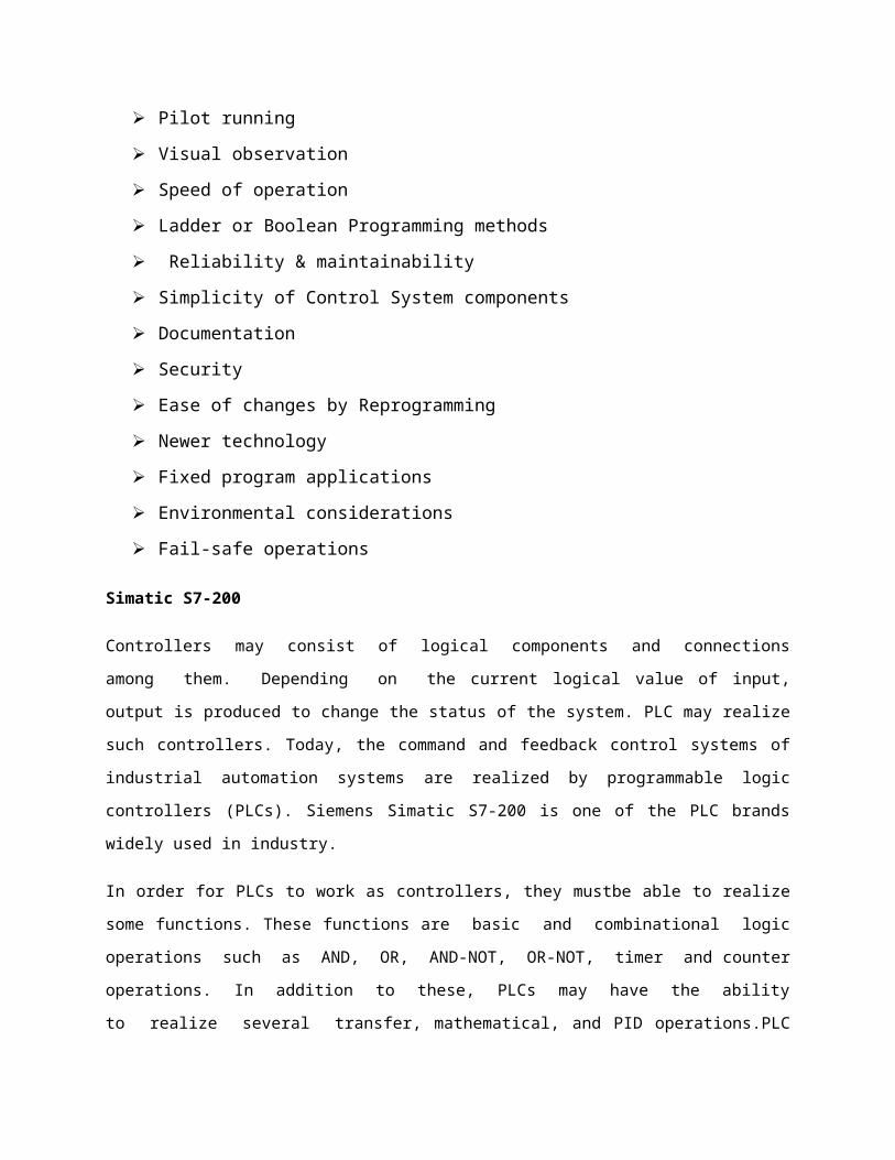
Ladder Diagram of NOR Gate
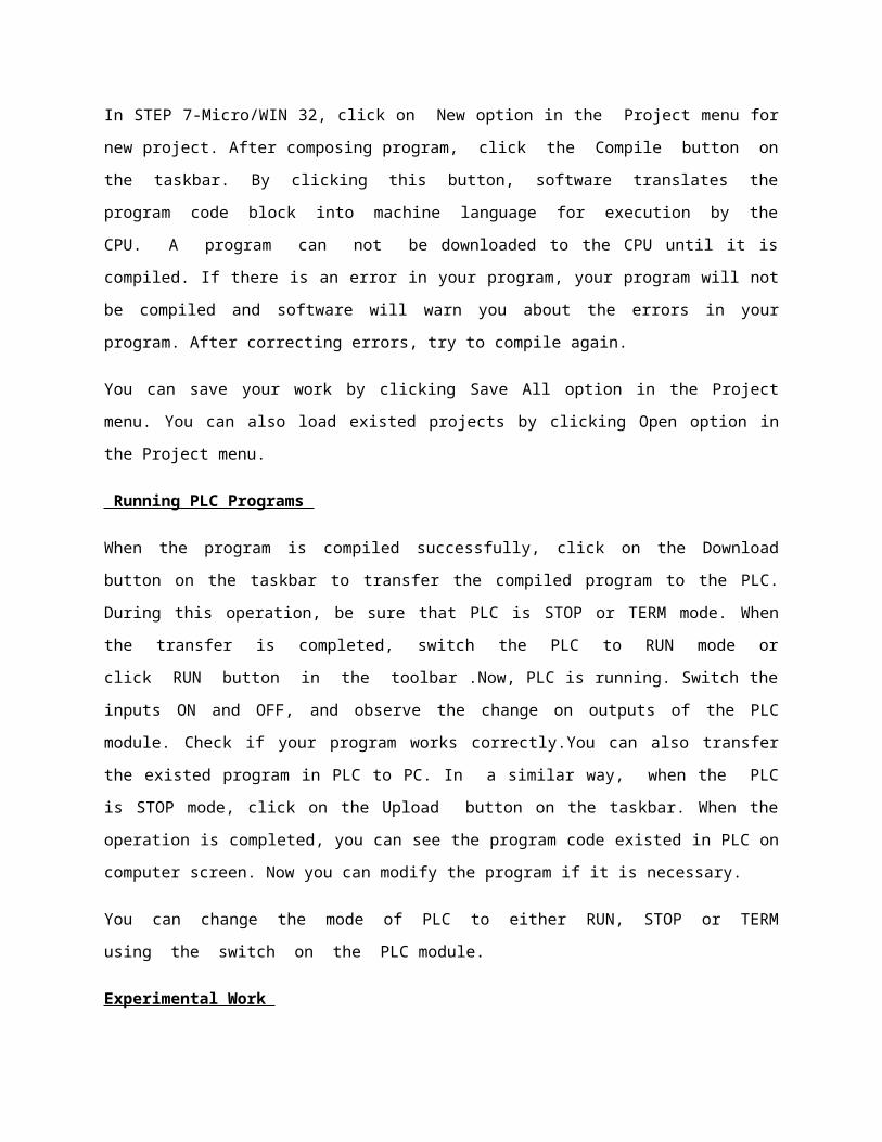
D FLIP FLOP.
DISCUSSION:
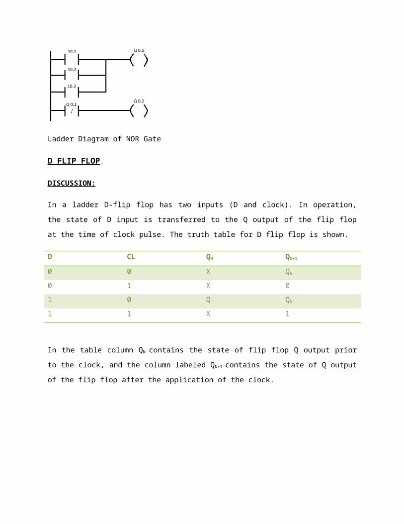
In a ladder D-flip flop has two inputs (D and clock). In operation, the state of D input is transferred to the
Q output of the flip flop at the time of clock pulse. The truth table for D flip flop is shown.
D CL QN QN+1

0 0 X QN
0 1 X 0
1 0 Q QN
1 1 X 1
In the table column QN contains the state of flip flop Q output prior to the clock, and the column labeled
QN+1 contains the state of Q output of the flip flop after the application of the clock.
A ladder D flip flop shown is a one rung function I0.1 and I0.2 and one coil Q 0.1 in this case I0.1 is the
input and I0.2 is the clock.
J-K FLIP FLOP
DISCUSSION:
The truth table for J-K Flip Flop is as under:-
J K CL Q n Q n+1
0 0 1 Q n Q n
0 1 1 X 0
1 0 1 X 1
1 1 1 Q n Q n
X X X Q n Q n

For this truth table, an X in any block indicates a “don’t care” condition, a 1 in the CL (clock) column
indicates the clock makes a 0 to 1 to 0 transition, and a 0 in the CL column indicates “don’t care”
condition, a 1 in the CL(clock) column indicates the clock makes a 0 to 1 transition, and a 0 in the CL
column indicates no clock transition. The Qn column contains the flip flop state prior to the application
of a clock, and the Qn+1 column contains the flip flop state after the clock. The ladder diagram
for a J-K flip flop in which 10.1=J, 10.2=K, 10.3=CL is shown in fig
Ladder Diagram of J-K Flip Flop
REVIEW QUESTIONS:
1.What do you mean by Toggling?
2.What will happen when clock pulse is not applied?
3.What do you mean by rung?
4.What will happen when the clock pulse is not applied?

5.What do you mean by Toggling?
6.What will happen when clock pulse is not applied?
EXPERIMENT WORK:
1.find the ladder logic of following.
OBSERVATIONS:
1.ASSIGNMENT LIST
2.LADDER LOGIC DIAGRAM.
3.STL LOGIC.

ES-423 Lab Grading Sheet
Lab 2Student Name:………………….. Roll No:…………..
Instructions Print this grading sheet, write your name and roll number at the top, and give it to the Instructor/lab Engineer during your lab check off. Include this as the cover page to your lab report. Instructor/Lab engineer Grading Section Check Off During your in-lab check off, be prepared to show the Instructor/Lab Engineer the following:
• The connections of the circuit of the experiment • Real Time values of the observed data • Properly Running the Machine within safe limits • Table containing Measurements and Calculations • Graph between the observed quantities
Reminder: This lab requires a Full Report Worksheet Score:
Instructor/Lab Engineer’s Comments:
_______ (of 5) Organization & Quality
_______ (of 5) Completeness & Correctness of Figures
_______ (of 5) Discussion Topics / Q & A
Instructor/Lab Engineer
DEPARTMENT OF ELECTRONIC ENGINEERING, SCE&T, RAHIM’YAR’KHAN
INDUSTRIAL ELECTRONICS (8TH SEMESTER, FINAL YEAR) EXPERIMENT # 3/16
Date Instructor/Lab Engineer Score (0-5)
Instructor/Lab EngineerReportScore (0-15)
TotalScore (0-20)

Name: ________________________________________Roll No: _____________________
Score: ______________Signature of the Lab Tutor: __________________Date: ____________
----------------------------------------------------------------------------------------------------------------------------
BIT LOGIC INSTRUCTIONS
OBJECTIVE:
Upon the successful completion of this experiment, the students will be able to
To study the operation of bit logic instructions.
To construct PLC program using the bit logic instructions.
REFERENCE:
John W.Webb.Ronald A.Reis, ”Programmable Logic Controllers”.
Bit Logic Instructions
CONTACTS
Standard Contacts
The Normally Open contact instructions (LD, A, and O) and Normally Closed contact instructions (LDN, AN, ON) obtain the referenced value from the memory or from the process-image register. The standard contact instructions obtain the referenced value from the memory (or process-image register if the data type is I or Q).
The Normally Open contact is closed (on) when the bit is equal to 1, and the Normally Closed contact is closed (on) when the bit is equal to 0. In STL, the Normally Open instructions Load, AND, or OR the bit valueof the address bit to the top of the stack, and the Normally Closed instructions Load, AND, or OR the logicalNOT of the
bit value to the top of the stack.
Immediate Contacts
An immediate contact does not rely on the S7-200 scan cycle to update; it updates immediately. The Normally Open Immediate contact instructions (LDI, AI, and OI) and Normally Closed Immediate contact instructions (LDNI, ANI, and ONI) obtain the physical input value when the instruction is executed, but the process-image register is not updated. The Normally Open Immediate contact is closed (on) when the physical input point (bit) is1, and the normally Closed Immediate contact is closed (on)

when the physical input point (bit) is 0. The Normally Open instructions immediately load, AND, or OR the physical input value to the top of the stack, and the Normally
Closed instructions immediately Load, AND, or OR the logical NOT of the value of the physical input point to the top of the stack.
NOT Instruction
The Not instruction (NOT) changes the state of power flow input (that is, it changes the value on the top of the stack from 0 to 1 or from1 to 0).
Positive and Negative Transition Instructions
The Positive Transition contact instruction (EU) allows power to flow for one scan for each off-to-on transition. Th Negative Transition contact instruction (ED) allowspower to flow for one scan for each on-to-off transition. For the Positive Transition instruction, detection of a 0-to-1 transition in the value on the top of the stacksets the top of the stack value to 1; otherwise, it is set to 0. For a Negative Transition instruction, detection of a1-to-0 transition in the value on the top of the stack sets the top of the stack value to 1; otherwise, it is set to 0.For run mode editing (when you edit your program in RUN mode), you must enter a parameter for the Positive Transition and Negative Transition instructions.
Table 2-1 Valid Operands for the Bit Logic Input Instructions
Coils
Output
The Output instruction (=) writes the new value forthe output bit to the process-image register. Whenthe Output instruction is executed, the S7-200 turns the output bit in the process-image register on or off. For LAD, the specified bit is set equal to power flow. For STL, the value on the top of the stack is copied to the specified bit.
Output Immediate
The Output Immediate instruction (=I) writes the new value to both the physical output and the corresponding process-image register location when the instruction is executed. When the Output Immediate instruction is executed, the physical output point (Bit) is immediately set equal to power flow. For STL, the instruction
immediately copies the value on the top of the stack to the specified physical output bit (STL). The “I” indicates an immediate reference; the new value is written to both the physical output and the corresponding process-image register location when the instruction is executed.This differs from the non-immediate references, which write the

new value to the process-image register only.
Set and Reset
The Set (S) and Reset (R) instructions set (turn on) or reset (turn off) the specified number of points (N), starting at the specified address (Bit). You can set or reset from 1 to 255 points.
If the Reset instruction specifies either a timer bit (T) or counter bit (C), the instruction resets the timer or counter bit and clears the current value of the timer or counter.
Set Immediate and Reset Immediate
The Set Immediate and Reset Immediate instructions immediately set (turn on) or immediately reset (turn off) the number of points (N), starting at specified address(Bit). You can set or reset from 1 to 128 points immediately.
The “I” indicates an immediate reference; when the instruction is executed, the new value is written to both the physical output point and the corresponding process-image register location. This differs from the non-immediate
references, which write the new value to the process-image register only.
Table 2-2 Valid Operands for the Bit Logic Output Instructions Contact instructions Coil instructions

Experimental Work
An automatic stamp system shown in Figure 2 works as follows: When start switch is turned on, system gets ready to run. When the operator puts a box at the beginning of the conveyor (on LS1) the motor runs and conveyor moves. Upon reaching the mid point of the conveyor (on LS2) the conveyor motor stops. Then the stamp comes down and puts the stamp on the box. When this process is
finished, the stamp goes up and conveyor moves again to the other end of the conveyor. After box reaches to end of the conveyor (on LS3), the motor stops. The system waits for the box to get and the another box to be placed at the beginning of the conveyor. If start switch is turned off, the system can not run even if there is a box on conveyor. The light on the start box indicates that the system is active whereas UPand Down lights indicate that the stamp is UP and DOWN position respectively. Develop a LAD to control the stamp system.
Figure 2. Automatic stamp machine

OBSERVATION:-
1.ASSIGNMENT LIST
2.LADDER LOGIC DIAGRAM.
3.STL LOGIC.