
A review of Cyclotron Accelerators for cancer diagnosis ...
95
A review of Cyclotron Accelerators for cancer diagnosis and treatment Olia Tsivitanidou Supervised by Professor Panos Razis Department of Physics University of Cyprus December 2020
Transcript of A review of Cyclotron Accelerators for cancer diagnosis ...
A review of Cyclotron Accelerators for
cancer diagnosis and treatment
Olia Tsivitanidou
Supervised by Professor Panos Razis
Department of Physics
University of Cyprus
December 2020

ii
To my daugther, Anna.

iii
Acknowledgements
I would like to express my sincerest gratitude to my thesis advisor, Professor Dr. Panos
Razis, for his continuous support and nurturing. I would also like to thank Dr. Yiannis Roussakis
and Mr. Panayiotis Hadjitheodorou (German Oncology Centre, Limassol), and Dr. Andri Peratikou
(Bank of Cyprus Oncology Centre, Nicosia) for providing essential pieces of information in
relation to cancer diagnosis and treatment methods currently being used in Cyprus. Last but not
least, I would like to thank my family and especially my husband Stathis, for the support, love,
and understanding, not only during the development of this thesis but also through my five-year
journey in studying Physics. I dedicate this work to my treasured daughter, Anna, who has been a
joyful companion halfway through this journey. It has been hard, due to other obligations, but still
a wonderful journey in the world of Physics. Ancora imparo (Michelangelo)!
© Tsivitanidou E. Olia, 2020

iv
ABSTRACT
The purpose of this thesis is the examination and comparison of cyclotrons that are
available in the international market for the production of imaging and therapeutic radioisotopes,
for the diagnosis and treatment of cancer, respectively. The research findings provide an overview
of 23 different cyclotron models manufactured by 6 suppliers. A detailed report and comparison
of their specifications are presented which vary in relation to the purpose of use of the cyclotrons.
Also, the types of radioisotopes that can be produced with those cyclotrons are investigated,
together with the nuclear reactions that take place, with a distinction between their use either for
imaging purposes or for radiotherapy. Finally, superconducting compact cyclotrons which are
suitable for irradiating cancerous tissues with protons are presented. The field of nuclear medicine
is expanding and the number of cyclotrons that provide the necessary isotopes is increasing.

v
ΠΕΡΙΛΗΨΗ
Ο σκοπός της διπλωματικής εργασίας είναι η μελέτη και η σύγκριση κυκλοτρονίων τα
οποία είναι διαθέσιμα στη διεθνή αγορά για παραγωγή απεικονιστικών και θεραπευτικών
ραδιοϊσοτόπων, για τη διάγνωση και θεραπεία του καρκίνου, αντίστοιχα. Τα ευρήματα της
έρευνας παρέχουν μια επισκόπηση 23 διαφορετικών μοντέλων κυκλοτρονίων που
κατασκευάζονται από 6 προμηθευτές. Παρουσιάζεται μια λεπτομερής έκθεση και σύγκριση των
προδιαγραφών τους οι οποίες ποικίλλουν σε σχέση με το σκοπό χρήσης των κυκλοτρονίων.
Επίσης, διερευνώνται τα είδη των ραδιοϊσοτόπων που μπορούν να παραχθούν με κυκλοτρόνια,
μαζί με τις πυρηνικές αντιδράσεις που λαμβάνουν χώρα, με διάκριση χρήσης αυτών είτε για
σκοπούς απεικόνισης, είτε για ραδιοθεραπεία. Τέλος, παρουσιάζονται διαθέσιμα στη διεθνή
αγορά υπεραγώγιμα συμπαγή κυκλοτρόνια κατάλληλα για ακτινοβόληση καρκινικών ιστών με
πρωτόνια. Ο τομέας της πυρηνικής ιατρικής επεκτείνεται συνεχώς και ο αριθμός των
κυκλοτρονίων που παρέχουν τα απαραίτητα ισότοπα αυξάνεται.

vi
Table of Contents
1. Introduction ......................................................................................................................................... 11
1.1. Problem formulation ................................................................................................................... 11
1.2. Aims of this thesis ....................................................................................................................... 14
1.3. Research questions ...................................................................................................................... 14
1.4. Significance of work ................................................................................................................... 15
2. Theoretical Framework ....................................................................................................................... 16
2.1. Matter and its structure ............................................................................................................... 16
2.2. Radioisotopes and radioactive decays ......................................................................................... 18
2.2.1. Stable and unstable atoms ................................................................................................... 18
2.2.2. Radioactive decays .............................................................................................................. 18
2.3. Nuclear Reactions ....................................................................................................................... 20
2.4. A charge inside an electric and magnetic field ........................................................................... 21
2.5. Fixed target and collision experiments ....................................................................................... 23
3. Particle Accelerators ............................................................................................................................... 25
3.1. Particle accelerators .................................................................................................................... 25
3.2. Brief history of accelerators and their medical applications ....................................................... 25
3.3. Parameters characterizing particle accelerators .......................................................................... 33
3.4. Types of particle accelerators ..................................................................................................... 36
3.4.1. Principles of Linear Accelerators ........................................................................................ 37
3.4.1.1. Constant Electric field (DC) (Electrostatic) Accelerators ........................................... 38
3.4.1.2. Alternating electric field (AC) accelerators ................................................................ 40
3.4.2. Principles of Circular Accelerators ..................................................................................... 40
3.5. Applications of particle accelerators ........................................................................................... 41
3.6. The Cyclotron ............................................................................................................................. 42
3.7. Different types of Cyclotrons ...................................................................................................... 48
4. Cancer diagnosis and treatment .......................................................................................................... 52
4.1. Cancer .............................................................................................................................................. 52
4.2. Diagnosis of cancer .......................................................................................................................... 53
4.3. Cancer treatment .............................................................................................................................. 55
4.3.1. Chemotherapy treatment ........................................................................................................... 55
4.3.2. Radiation therapy ...................................................................................................................... 56
5. Methodology ....................................................................................................................................... 59
5.1. Strategic approach ....................................................................................................................... 59

vii
5.2. Data analysis ............................................................................................................................... 60
6. Results ................................................................................................................................................. 61
6.1. Cyclotrons in the market ............................................................................................................. 61
6.2. Cyclotron models’ specifications ................................................................................................ 62
6.2.1. Advanced Cyclotron Systems Inc. (ACSI) ......................................................................... 63
6.2.2. Best Cyclotrons Systems Inc (BCSI) .................................................................................. 67
6.2.3. IBA ...................................................................................................................................... 70
6.2.4. KIRAMS ............................................................................................................................. 73
6.2.5. GE Healthcare ..................................................................................................................... 75
6.2.6. VARIAN ............................................................................................................................. 75
6.3. Accelerator-Produced Isotopes ................................................................................................... 81
6.3.1. Radioisotopes for scientific research .................................................................................. 81
6.3.2. Radioisotopes for pharmaceutical and medical applications .............................................. 81
7. Discussion and Conclusions................................................................................................................ 84
7.1. Cyclotron in the market for medical isotopes production ........................................................... 84
7.2. Cyclotron technical specifications and design requirements ...................................................... 84
7.3. Radioisotopes for PET/SPECT imaging, radiotherapy, and radiotracers ................................... 87
7.4. Limitations .................................................................................................................................. 88
7.5. Concluding remarks .................................................................................................................... 89
8. References ........................................................................................................................................... 91

viii
Tables of Graphs and Figures
Figure 1. A particle in a cyclotron .............................................................................................................. 22
Figure 2. The Van de Graaff generator ....................................................................................................... 27
Figure 3. Picture of a Cockroft-Walton accelerator .................................................................................... 27
Figure 4. Linacs introduced in 1928 at the RWTH Aachen University ...................................................... 28
Figure 5. First cyclotron invented by Ernest O. Lawrence ......................................................................... 29
Figure 6. The Bragg peak for electrons, X-rays and protons ...................................................................... 30
Figure 7. The Accelerator Complex of the European Organization for Nuclear Research, CERN ............ 31
Figure 8. A schematic map showing the Future Circular Collider tunnel at the site of CERN .................. 32
Figure 9. Collider luminosity (per bunch crossing) .................................................................................... 34
Figure 10. Principle of electrostatic accelerators ........................................................................................ 38
Figure 11. Diagram of a Cockroft-Walton accelerator ............................................................................... 39
Figure 12. Diagram of a Tandem Van de Graaff accelerator ...................................................................... 39
Figure 13. Graphical illustration of a linear accelerator and its operation principle ................................... 40
Figure 14. Graphic representation of the cyclotron’s basic function .......................................................... 43
Figure 15. The electric and magnetic field of a cyclotron .......................................................................... 44
Figure 16. The spiral path of a proton in a cyclotron .................................................................................. 44
Figure 17. A simplified cross-section and plan view of a ‘classical’ cyclotron .......................................... 46
Figure 18. Different pole shapes for AVF isochronous cyclotrons ............................................................ 47
Figure 19. Magnet pole of an isochronous cyclotron .................................................................................. 50
Figure 20. Operating principle of PET scans .............................................................................................. 54
Figure 21. Dose distribution for a proton and photon craniospinal plan..................................................... 57
Figure 22. TR-24 cyclotron manufactured by ACSI ................................................................................... 65
Figure 23. TR-30 cyclotron manufactured by ACSI ................................................................................... 66
Figure 24. The TR-FLEX cyclotron compared to TR-30 .......................................................................... 66
Figure 25. The Best 15p Cyclotron ............................................................................................................. 67
Figure 26. The Best 25p Cyclotron ............................................................................................................. 68
Figure 27. The Best 35p Cyclotron ............................................................................................................. 69
Figure 28. The Best 70p Cyclotron ............................................................................................................. 70
Figure 29. Beam line layout of a Best 70p cyclotron .................................................................................. 70
Figure 30. The Cyclone 3d of IBA ............................................................................................................. 71
Figure 31. The Cyclone 30 of IBA ............................................................................................................. 71
Figure 32. The Cyclone 70 of IBA ............................................................................................................. 72
Figure 33. S2C2 layout ............................................................................................................................... 73

ix
Figure 34. KIRAMS-13 cyclotron .............................................................................................................. 74
Figure 35. KIRAMS-30 cyclotron .............................................................................................................. 74
Figure 36. Varian cyclotron: 1—sector shim, 2—dee, 3—magnet yoke .................................................... 76
Figure 37. ProBeam VARIAN Platform ..................................................................................................... 76

x
Table of tables
Table 1. First, second and third generation particles (classification of matter) .......................................... 17
Table 2. Centre of mass energy for different types of collisions ................................................................ 24
Table 3. Radionuclides used in PET medical imaging .............................................................................. 54
Table 4. Cyclotrons vendors examined ....................................................................................................... 59
Table 5. Cyclotron models manufactured by cyclotron vendors ................................................................ 61
Table 6. Comparison of commercial cyclotrons for medical applications .................................................. 77
Table 7. Comparison of commercial cyclotrons for medical applications (continuation). ......................... 79
Table 8. List of medical isotopes produced by cyclotrons .......................................................................... 82
Table 9. Typical radionuclides used for cancer diagnosis and therapy ....................................................... 87
11
Chapter 1
1. Introduction
1.1. Problem formulation
Cancer treatment is one of the main priorities of the European Commission in the health
domain, while protecting and promoting public health comprises one of the top priorities of the
Political Guidelines set for the next European Commission, 2019-2024. As part of this, Member
States are prompted to improve cancer prevention, diagnosis, treatment, and care [1]. On the 4th of
February 2020, the European Commission started the public consultation of this strategic plan at
an event entitled ‘Europe’s Beating Cancer Plan: Let’s Strive for More’ in the European
Parliament in Brussels. This priority has been set since cancer is the second leading cause of
mortality in the EU countries after cardiovascular diseases, accounting for 26% of all deaths in
2013. More than 1,3 million people died of cancer in 2013 across all EU Member States [2].
Mortality from cancer is also the second leading cause of death in Cyprus [3], with high
frequencies of lung cancer incidents, and especially breast cancer for women and prostate cancer
for men, with the number of people dying from this disease nearly doubling between 2004 and
2014 [3]. The above data stress the need for research and investing in mechanisms and methods
that can efficiently and accurately diagnose and treat cancer incidents, in addition to the methods
which are currently used on a large scale.
There are several methods to diagnose cancer, including a laboratory tests, imaging tests
and biopsy, always in correlation to the clinical presentation and clinical view. Indications for the
potential presense of cancer to a patient’s baody may often be revelaed acccidentaly during a
physical exam or when the patient does not fell well and experiences particular cancer signs. As a
next step, a series of subsequent processes is followed, for the so-called staging determination, that
is, to diagnose the stage of the cancer, its type and exact location. Imaging techniques are often
being applied, including computerized tomography (CT) scanning for identifying a tumor’s shape,
size, and location through cross-sections of the body. Other imaging tests include magnetic

12
resonance imaging (MRI). Yet, for more than two decades, applications of Positron Emission
Tomography (PET) molecular imaging–directed biopsy of a variety of organs has been introduced
in oncology for the management of various diseases, with a focus on cancers [4] as well as SPECT
(single photon emission computed tomography) scans. PET scanners usually incorporate a CT
(computed tomography) scanner and are known as PET-CT scanners. PET scan images can be
reconstructed using a CT scan performed using one scanner during the same session. An advantage
that a PET-CT scan offers in comparison to other imaging techniques (e.g. CT scan) apart from
imaging of tumours, is the ability to search for metastases within the field of clinical oncology,
and for the clinical diagnosis of certain diffuse brain diseases, such as those causing various types
of dementias. PET uses radioactive substances known as radiotracers to visualize and measure
changes in metabolic processes, and in other physiological activities including blood flow, regional
chemical composition, and absorption. Different tracers are used for various imaging purposes,
depending on the target process within the body. The most widely used radiopharmaceutical used
to detect cancer is the Fluorodeoxyglucose 18F-FDG which is injected to body, most often
intravenously, to act as a tracer. Radiopharmaceuticals are composed after certain radioisotopes
undergo chemical procedures. Then, gamma rays are emitted and detected by gamma cameras to
form a three-dimensional image. Radioisotopes occur after a high energy beam bombards a given
target.
Cyclotrons are one of the most prevalent forms of accelerators used to make radioisotopes
(radioactive atoms) that can be used for medical imaging, as mentioned above, and research.
Cyclotrons comprise circular particle accelerators in which charged particles (e.g., protons)
accelerate in a spiral trajectory outward from the machine’s centre, due to the presence of an
accelerating electric voltage and then steered along their path by a magnetic field. Once the high-
speed and high-energy charged particles get to the edge of the cyclotron chamber, they are directed
down the beamlines where they are used in physics experiments or to produce radioisotopes for
nuclear medicine and other purposes. For medical applications, a cyclotron produces isotopes,
such as the Fluoride-18 (18F) for positron emission tomography (PET) scanning, and Carbon-11
(11C) and nitrogen-13 (13N) for research uses.
Although the primary use of the cyclotron-produced short-lived radioisotopes is in PET-
CT and SPECT diagnostic medical procedures, cyclotrons are also capable of producing longer-
lived isotopes for therapeutic procedures or simply using their configured particle beams for
irradiation of carcinogenic tissues. Radiopharmaceutical therapy (RPT) is emerging as a safe and
effective targeted approach to treating many types of cancer [5]. In RPT radiation is systemically
or locally delivered using pharmaceuticals that either bind preferentially to cancer cells or
accumulate by physiological mechanisms. Almost all radionuclides used in RPT emit photons that
can be imaged, enabling non-invasive visualization of the biodistribution of the
diagnostic/therapeutic agent. Compared with almost all other systemic cancer treatment options,
RPT has shown efficacy with minimal toxicity.

13
In relation to cancer treatment, alongside chemotherapy, surgery, and RPT which is an
emerging field, radiotherapy (RT) has evolved to become one of the essential therapies for the
treatment of cancer. Following chemotherapy, which is a drug treatment with multiple side effects
[6, 7], the most common radiation therapy worldwide is carried out with photons (usually x-rays).
Multiple X-ray beams deliver radiation to the tumour target but unavoidably this procedure
deposits radiation in the normal tissues beyond the target, potentially damaging those tissues as
the beam exits the body. Proton therapy for cancer treatment is a new type of irradiation, in which
the rays consist of charged nuclei (=ions) of hydrogen atoms and destroy tumour cells more
effectively, as compared to the conventional radiation treatment, since the location of the proton
beam’s Bragg peak is highly localized [8] and protons are low linear energy transfer (LET)
radiation. However, the depth that an energetic proton will penetrate matter (i.e. human body in
this case) varies with energy, and therefore, when selecting the appropriate protons’ energy, this
can be delivered precisely in a tumour. That is why one of the advantages of using proton therapy
for tumour treatment, is the low risk for side effects, and in particular the potential damage of
healthy cells. This occurs since the radiation damage to the body, during entry, is significantly less
than in the tumour. Also, little damage is done behind the tumour, as the latter stops the penetrated
beam of photons.
Therefore, proton therapy is argued to be more effective compared to traditional radiation
(e.g., photon or electron therapy), as it leads to significantly lower risk of side effects, by delivering
a higher radiation dose to tumours and a lower dose to healthy tissue compared to standard
radiation therapy. However, this advantage may be also a drawback since high precision is required
in targeting the tumour for the proton therapy to become effective. Υet, it requires a high cost for
its facilities’ installation and operation, which may be considered inappropriate for the size of the
Cypriot population. Overall, the high cost of installing and operating proton therapy facilities, but
also the high precision required for effectively applying the method, comprise limitations. Proton
therapy has been recommended especially for optic melanoma and paediatric tumours. Such cancer
cases identified in the Cypriot population at the moment are receiving proton therapy treatment
abroad. Particle accelerators used for proton therapy, such as cyclotrons, typically produce protons
with energies in the range of 70 to 250 MeV.
Given the above-mentioned developments in medical physics for cancer diagnosis and
treatment, it becomes apparent that the cyclotron has a central role to play in this direction. Yet
only one small cyclotron and a PET-CT scan are currently available in Cyprus, placed at the
German Oncology Centre (GOC) in Limassol, which are used for cancer diagnosis via onsite
production and utilisation of diagnostic radionuclides. The cyclotron is an ABT BG-75 medical
cyclotron, with energy 7.5 MeV. At GOC the following radionuclides are used: [18F]FDG,
[18F]F-PSMA-1007, Na[18F]F, [18F]FMISO, [18F]FET, [18F]FLT, [18F]FES, [18F]F-L-DOPA,
[18F]FCholine, [18F]-SiFA-lin-TATE, Al[18F]F-FAPI-74.
In addition, some potential investors have announced that they would be interested to
establish a proton therapy facility in Cyprus, [9] an interesting project for the benefit of the society

14
that would, however, require a certain synergy among several countries in the geographical region
of Cyprus.
Overall, examining and understanding how cyclotrons operate and what their requirements
and technical specifications are, becomes imperative given the recent developments in the region.
1.2. Aims of this thesis
This thesis is focusing on the use of cyclotrons for radioisotopes production. In particular,
the purpose of this thesis is to examine cyclotrons available in the international market, which can
be used to produce imaging and therapeutic isotopes, for diagnosis and treatment of cancer,
respectively. In addition, various accelerator-produced radionuclides and their primary areas of
medical applications are examined. The current literature, reports and documentation by policy
makers and relevant stakeholders, are very helpful as accelerators manufactured by international
companies are examined to this end.
An introduction to the problem, the purpose of this work and its significance are provided
in Chapter 1. Then, a theoretical framework follows in Chapter 2, including essential pieces of
information on our understanding of matter, its structure, radioisotopes and radioactive decays,
nuclei reactions as well as basic principles of physics applied to an electric charge inside an electric
and magnetic field, in fixed target and collision experiments. These elements are very important
for understanding the principles applied in the operation of a cyclotron. Chapter 3 is devoted to
particle accelerators in general, including a presentation of a brief history of accelerators and their
medical applications, a description of different types of particle accelerators currently operating,
concluding with emphasis on the technical specifications and operation features of cyclotron.
Chapter 4 offers an overview on cancer and the typically followed practices for cancer diagnosis
and treatment. Chapter 5 presents the methodology followed to collect information and analyse
data from companies that manufacture accelerator systems, in particular cyclotrons. This includes
research papers and reports, which were then subjected to scrutiny and analysis. The results of this
inquiry are presented in Chapter 6, followed by a discussion and conclusions in Chapter 7 of the
thesis.
1.3. Research questions
The following research questions guided this inquiry:
1. Which are the available in the market cyclotron models that produce medical
isotopes?
2. What are the technical specifications of the identified cyclotron models?
3. What type of (PET/ SPECT/ therapeutic) radioisotopes can be produced with the
facilitation of these cyclotrons?
15
1.4. Significance of work
The findings of this thesis provide essential pieces of information to medical institutions,
healthcare organizations and stakeholders, but also academic institutions who aim to proceed with
the implementation and installation of a cyclotron in Cyprus for either diagnostic or therapeutic
purposes. In particular, useful information is provided in relation to cancer diagnosis and
treatment, and a useful mapping of available cyclotrons on the market and their specifications, as
well as ways to use those for the diagnosis and treatment of cancer, and the possibilities of using
them for research purposes. The results can be used to support the argument for the installation of
a second cyclotron in Cyprus through appropriate documentation. Adhering the potential
limitations and risks which are also discussed, an installation of a second cyclotron in Cyprus,
larger with a higher capacity in the production of radiopharmaceuticals, will lead to the following
benefits for the scientific community, the local economy and society at large: (1) the expansion of
the methods currently being used for diagnosis and treatment of cancer and degenerative brain
diseases with health and medical implications, (2) a new area of research in the field of medical
physics and interdisciplinary research, (3) new work posts for young researchers and cyclotron
staff coming from different areas of studies and specialization.

16
Chapter 2
2. Theoretical Framework
2.1. Matter and its structure
The atomic structure of matter, as a philosophical idea at least, has its origins to Lefkippos
and Democritus (4th century BC). It was not until the 18th century that Antoine Laurent Lavoisier,
along with a whole host of other scientists, confirmed the validity of this view in their experiments.
At the beginning of the 20th century, Ernest Rutherford was able to show that the atom has a very
compact, and relatively small, core, while the rest of the space seemed empty. His main experiment
was to bombard a thin sheet of gold with α particles (now known to be helium nuclei, He) at a very
high speed. While most of these particles pierced the sheet with very small deviations, some were
observed to be scattered. The observations from Rutherford’s experiment would fit in a model
according to which the atom's nucleus is positively charged and placed in the centre of the atom,
while, according to Rutherford, a multitude of (negatively charged) electrons fills in the empty
space. In 1913, Niels Bohr put the electrons in their “position”, that is, to rotate in orbits around
the nucleus. Electrons should move around the nucleus but only in prescribed orbits (the electron
had already been discovered by Joseph John Thomson a few years ago).
A series of new experiments, that took place in the first decades of our century, have given
new information on the structural components of the atomic nucleus. The proton, with a positive
electric charge (the absolute value of the electron), and the neutron that it has almost the same
mass as the proton but is electrically neutral, were proven to be the two kinds of particles
composing the nucleus of the atom.
In the 1960s and 1970s it became clear, initially theoretically and then experimentally
confirmed, that protons and neutrons are not fundamental but have an internal structure: that is,
they consist of smaller particles called quarks. Quarks come in two types: the up quark and the

17
down quark. The quarks are electrically charged: the upper quark has a charge of +2/3 (in units of
the electron charge we consider having a charge of -1), while the lower quark has a charge of -1/3.
The proton mainly consists of 2 upper quarks and 1 lower quark, while the neutron has 2 lower
quarks and 1 upper quark. Today's science of matter structure, the physics of fundamental particles,
needs only 4 basic building blocks to build today's world. The upper and lower quarks, the electron
and in addition a very strange particle, the neutrino. The latter had been predicted by Wolfgang
Pauli since 1930, but it was only in 1956 that its existence was proved experimentally. It is a neutral
electric particle with a surprisingly small mass (in fact its mass is smaller than the error made by
experimental devices and we theoretically treat it as having no mass, which is perfectly acceptable
in the special theory of relativity). The neutrino appears as a product of neutron decay. Electron
and neutrino are called leptons (from the word “thin”).
Although these four particles form the substance of the entire universe, in the experiments
that we currently perform (and, as we believe, also in the first seconds of the creation of the
universe), other particles appear but have striking similarities to the four mentioned above and
what we call the 1st generation particles. In fact, there are two more generations of particles, each
with 2 leptons and 2 quarks. In the second generation we have the particle μ (muon) and its own
neutrino (different from the first generation) for leptons, as well as the charm and strange quark
with loads exactly corresponding to the first-generation particles (see Table 1). Similarities persist
in properties other than mass: the second generation is heavier than the first. The third generation
shows its particle τ (tau) and its own neutrino for leptons and the high (top) and the low (bottom)
quarks (other names top and bottom). Again, the third generation appears even heavier. It is a fact
that the existence of the three generations, with identical characteristics, is one of the still
unanswered questions of Elementary Particle Physics. Experiments, however, suggest the
existence of three and not more generations.
Table 1. First, second and third generation particles (classification of matter)
Type Generation of matter
First Second Third
Quarks
Up-type Up (q = +2/3) Charm Top
Down-type Down (q = -1/3) Strange Bottom
Leptons
Charged Electron (q= -1) muon Tau
Neutral Electron neutrino (q =
0)
Muon neutrino Tau neutrino
Therefore, we could say that a total of 12 particles are the basic building blocks of the
universe, from its birth until today. However, modern theory that describes the microcosm,
quantum mechanics, predicts (and has been experimentally proven) the existence of opposite
particles. Each particle corresponds to another, with the same mass and opposite electric charge.
Thus, the total number of fundamental particles doubles.

18
2.2. Radioisotopes and radioactive decays
Another important part of the background knowledge to consider is that of radioisotopes
and radioactive decays. The reason for looking at this, is due to the fact that particle accelerators
operate on the foundation of the artificial production of radionuclides, which occur in radioactive
decays.
2.2.1. Stable and unstable atoms
For understanding the nature of stable and unstable atoms there is a need to first identify
how the atomic particles interact to one another. First, the electrons are kept in orbit around the
nucleus due to the existence of an electromagnetic field of attraction between the positive charge
of the protons and the negative charge of the electrons. Then, in a nucleus level, the so-called
strong force opposes and overcomes the force of repulsion between the protons and holds the
nucleus together. The net energy associated with the balance of the strong force and the force of
repulsion is called the binding energy. When the binding energy is great enough for holding the
nucleus together, then this nucleus is characterized as stable. However, in some atoms the binding
energy is not strong enough to hold the nucleus together, and the nuclei of these atoms are said to
be unstable. Unstable atoms, or often called radioactive atoms, attempt to become stable by
ejecting nucleons (protons or neutrons), as well as other particles, or by releasing energy in other
forms. The additional energy imposed to unstable atomic nuclei is released through various
radioactive decay processes, by emitting radiation in the form of particles (neutrons, alpha, and
beta particles) or electromagnetic radiation (gamma-ray photons) [10]. Concluding, radioisotopes
are unstable atomic nuclei that undergo decay with emission of gamma rays or subatomic particles.
They can be created when accelerated energetic particles impinge on stable isotopes. The unique
properties of radionuclides have led to numerous applications in pure and applied scientific
research, medicine, and industry [11].
2.2.2. Radioactive decays
Radioactive decay (also known as nuclear decay, radioactivity, radioactive disintegration,
or nuclear disintegration) is the process by which an unstable atomic nucleus loses energy by
radiation. A material containing unstable nuclei is considered radioactive. Three of the most
common types of decay are alpha decay, beta decay, and gamma decay, all of which involve
emitting one or more particles or photons.
According to the radioactive decay law, the probability per unit time that a nucleus will
decay is a constant, independent of time. This constant is called the decay constant and is denoted
by λ, “lambda”. The radioactive decay of certain number of atoms (mass) is exponential in time.
𝑁 = 𝑁𝑜𝑒−𝜆𝑡 (radioactive decay law) (1)

19
Where, N: number of nuclei at time t, 𝑁𝑜: initial number of nuclei at time t=0, λ: decay
constant.
A radioactive decay is a random process at the level of single atoms, in that, according to
quantum theory, it is impossible to predict when a particular atom will decay. For that reason, the
probability that a nucleus will decay follows the Poisson distribution of random events.
𝑃(𝑁) = �̅�𝑁
𝑁!𝑒−�̅�, 𝜎 = √�̅� (2)
Where, �̅�: the mean number of nuclei, σ the error.
During its unpredictable decay, an unstable nucleus spontaneously and randomly
decomposes to form a different nucleus (or a different energy state – gamma decay), giving off
radiation in the form of atomic particles or high energy rays. The rate of nuclear decay is also
measured in terms of half-lives. The half-life is the amount of time it takes for a given isotope to
lose half of its radioactivity. It derives from the following equations.
𝑡 = 𝑇1/2 (3)
𝑁 =𝑁𝑜2
(4)
𝑁 = 𝑁𝑜𝑒−𝜆𝑡 (5)
𝑁𝑜2= 𝑁𝑜𝑒
−𝜆𝑇1/2 (6)
−𝜆𝑇1/2 = −𝑙𝑛2 (7)
𝑇1 2⁄ =𝑙𝑛2
𝜆
(8)
The radioactive decay law can be derived also for activity calculations or mass of
radioactive material calculations:
𝐴 = 𝐴𝑜𝑒−𝜆𝑡 (activity), 𝐴 = |
𝑑𝑁
𝑑𝑡| = 𝜆𝑁 =
𝑙𝑛2
𝑇1 2⁄ 𝑁 (9)
where N is the total number of particles in the sample, A (total activity) is the number of
decays per unit time of a radioactive sample.
Radioisotopes are unstable atomic nuclei that undergo decay with emission of gamma rays
or subatomic particles. They can be created when accelerated energetic particles impinge on stable
isotopes [11]. The unique properties of radionuclides have led to numerous applications in pure
and applied scientific research, medicine, and industry. Most radioisotopes used in medical therapy
emit β particles (electrons 𝑒− and positrons 𝑒+), which are ionizing radiations. The biological
effect is often described by the linear energy transfer (LET) which is the amount of energy that an

20
ionizing particle transfers to the material traversed per unit distance and is expressed in units of
keV/μm. LET is a measure of the energy deposited along the particle track and describes the action
of radiation into matter.
Nuclear medicine relies on the decay of radioisotopes to produce useful radiation for the
diagnosis and treatment of diseases. In nuclear medicine procedures, radionuclides are combined
in compounds to form radiopharmaceuticals that can localize in specific organs or cells. A new
class of radionuclides [12], including Tb149, Bi213, Po211, At211, Ra223, Ac225, Ac227, Th226, and U230,
which emit α particles (𝐻𝑒22) have been considered for therapy too. The LET for most therapeutic
α emitters ranges from 25 to 230 keV/μm. On the other hand, β particles emitted in nuclear β
decay, and in internal conversion processes, have kinetic energies ranging from tens of keV to
several MeV and their LET is much lower, typically ∼0.2 keV/μm.
A third type of ionizing radiation relates to the so-called Auger electrons (Auger, 1925),
named after the French physicist Pierre Victor Auger. This radiation process occurs when an inner-
shell electron is removed from an atom, so that the vacancy is then filled by an electron from the
outer shells and the excess energy is released as an X-ray photon, or by the emission of an Auger
electron. X-ray and Auger electron emission are competing processes and are both atomic
radiations. The atomic transition rates, and whether X-ray or Auger emission is dominant, depend
on the atomic number, the electron shells involved, and the electron configuration of the atom. The
full relaxation of the inner shell vacancy is a multistep process, resulting in cascade of atomic
radiations. The energy of emitted X-rays and/or Auger electrons depends on the atomic number,
the electron shells and electron configuration involved, and is typically in the range from a few eV
to 100 keV. Due to their short range (nm to μm), Auger electrons with relatively low energies can
have a much higher LET. For example, for electron energies below 1 keV the LET peaks at around
26 keV/μm [13]. In comparison to α or β particles, Auger electrons have a much shorter range in
material, which makes them ideal tools for targeted radiation therapy [14]. However, since the
early 70s, when the exploitation of Auger electrons for tumour therapy was first suggested,
considerable advances have been made in the understanding of the radiobiological effect of low-
energy electrons.
2.3. Nuclear Reactions
A nuclear reaction is the process in which two nuclei, or a nucleus and an external
subatomic particle, collide to produce one or more new nuclides. This process results to the
transformation of at least one nuclide to another. The term nuclear reaction may refer either to a
change in a nuclide induced by collision with another particle, or to a spontaneous change of a
nuclide without collision. Therefore, collided nuclide may come from a reactor or accelerator or
from a radioactive source. The first such nuclear reactions were done in Rutherford’s laboratory,
using particles from a radioactive source [15]. As part of those experiments, the α particles merely
rebounded from the target nuclei, which is the so-called Rutherford scattering phenomenon,
indicating the existence of atomic nuclei. In other experiments, Rutherford was able to observe a

21
change or transmutation of nuclear species, as in the reaction given below that was first studied in
1919.
𝐻𝑒24 + 𝑁 → 𝑂 + 𝐻1
1817
714 (10)
The first particle accelerator capable of inducing nuclear reactions was built by Cockcroft
and Walton, who in 1930 observed the following reaction.
𝑝11 + 𝐿𝑖 → 2 𝐻𝑒 + 17.2𝑀𝑒𝑉2
437 (11)
In principle, a typical nuclear reaction is written as in eq. (13) that follows.
𝑎 + 𝑋 → 𝑌 + 𝑏 (12)
𝑋(𝑎, 𝑏)𝑌 (13)
An alternative and compact way of indicating the same reaction is given by eq. (14) where
a is the accelerated projectile, X is the target (usually stationary in the laboratory), and Y and b
are the reaction products. Also, Y is usually considered to be the recoil, while b is the product
detected and measured (ejectile). Generally, α and b comprise nucleons or light nuclei, but
occasionally b will comprise a γ ray, in which case the reaction is called radiative capture.
2.4. A charge inside an electric and magnetic field
The operation of a classical1 cyclotron, but also that of other types of particle accelerators
[16], is founded on the way in which the ionised particles behave inside an electric and magnetic
field. For that reason, this sub-chapter is devoted to the basic knowledge that one should consider
when examining cyclotrons, and particle accelerators in general. In cyclotrons an electric field is
used to accelerate ions, such as protons or deuterons, and a magnetic field is also applied to ‘guide’
the beam. Given that, the ionised particles receive forces, due to the existence of the electric and
magnetic fields. An electric field is generated with the application of an electric potential
difference U to two electrodes. A charge Q experiences a force and is accelerated. Its kinetic energy
T equals to:
𝑇 = 𝑄𝑈 (14)
For single charged ions, like protons and deuterons, the kinetic energy equals to 1 eV for a
potential difference of 𝑈 = 1𝑉. This suggests that for obtaining protons with energy 10 MeV, one
needs to apply 10 MV and this is rather unpractical. An ion with charge Q moving with velocity
1 By classical cyclotron, we refer to this type of quasi-uniform magnetic field. It operates like the first cyclotron that
was invented in 1932 by Lawrence and Livingston [17].

22
𝑣 ⃗⃗⃗ perpendicular to a magnetic field with magnetic induction 𝐵 ⃗⃗ ⃗ experiences the Lorentz force 𝐹𝐿⃗⃗ ⃗
given by the following equation:
𝐹𝐿⃗⃗ ⃗ = 𝑄(𝑣 𝑥 �⃗� ) (15)
As the ion is deviated from its original direction, it experiences a centrifugal force 𝐹𝑓⃗⃗ ⃗ .
𝐹𝑓⃗⃗ ⃗ =𝑚 𝑣2
𝑟
(16)
Given that the centripetal force 𝐹𝑓⃗⃗ ⃗ is the Lorentz force (here 𝐹𝐿⃗⃗ ⃗), the ion will follow a
circular equilibrium orbit with radius r, in a plane perpendicular to the magnetic field 𝐵 ⃗⃗ ⃗ (Figure
1). Matching the above two equations we obtain the angular velocity (ω):
𝑄𝑣𝐵 =𝑚 𝑣2
𝑟 𝑦𝑖𝑒𝑙𝑑𝑠→
𝑄𝐵
𝑚=𝑣
𝑟= 𝜔
(17)
Figure 1. A particle in a cyclotron [17]
As derived from the above equation, the angular velocity (ω) is determined by the nature
of the ion (its charge and mass) and the magnetic induction 𝐵 ⃗⃗ ⃗ and is independent of the radius of
the equilibrium orbit r. Relying on the above, the non-relativistic kinetic energy 𝑇 can be calculated
as follows:
𝑇 =𝑚 𝑣2
2=𝑚
2 (𝑄𝐵𝑟
𝑚)2
=𝑄2𝐵2𝑟2
2𝑚=𝑚𝜔2𝑟2
2
(18)
From the last two equations (17) and (18), the following conclusions can be drawn: (a) the
kinetic energy T is determined by the nature of the ion (Q, m), the magnetic induction B, and the
radius of the equilibrium orbit r; (b) the magnetic induction B is related to the angular velocity ω
by the nature of the ion (Q, m); (c) the kinetic energy T, the velocity v, and the radius of the
equilibrium orbit r, are correlated to each other for a given ion (Q, m) and magnetic field B
accelerators [16].

23
The above-mentioned equations and the attained conclusions are used in sub-chapters of
this thesis, later, for describing and analysing the operation of cyclotrons and synchrocyclotrons.
2.5. Fixed target and collision experiments
In general, for determining the energy available in the centre of mass system, assuming
that we have two particles of mass m: particle 1 energy and momentum 𝐸1, 𝑝1, and particle 2
energy and momentum 𝐸2, 𝑝2, the energy in the centre of mass 𝐸𝑐𝑚 can be found by using the
equation given below:
√(𝐸1 + 𝐸2)2 − (𝑝1 + 𝑝2)2𝑐2 = (𝑀 𝑐2)2 (19)
In the case of a collider where the target is at rest in the laboratory frame (i.e., 𝑝2⃗⃗⃗⃗ = 0), the
equations give:
(𝐸1 + 𝐸2)2 − 𝑝1
2𝑐2 = 𝐸𝑐𝑚2 − (𝑝1𝑐𝑚 + 𝑝2𝑐𝑚)
2𝑐2 (20)
(𝐸1 + 𝐸2)2 − 𝑝1
2𝑐2 = 𝐸𝑐𝑚2 (21)
𝐸𝑐𝑚 = √𝐸2 (𝐸2 + 𝐸1) + (𝑚1𝑐2)2 (22)
𝐸1 =𝐸𝑐𝑚2 − 𝐸2
2 − (𝑚1𝑐2)2
2𝐸2
(23)
When one particle is at rest, i.e. in the case of the so-called fixed target experiment (i.e.
𝑝2⃗⃗⃗⃗ = 0), the energy available in the centre of mass system is provided by equation (22). In other
words, in fixed-target experiments, the accelerated particle (with 𝑚1 𝑎𝑛𝑑 𝐸1,𝑙𝑎𝑏) bumps into a
stationary target of material (with 𝑚2) depending on the needs of the experiment. In addition to
the fixed-target experiments, there are also collision experiments in which two oppositely moving
beam of particles (with energies 𝐸1 and 𝐸2) collide at predetermined points in their orbit. In the
case of a collider where the collision point is at rest in the laboratory frame (i.e. 𝑝1 = - 𝑝2), the
centre of mass energy becomes:
𝐸𝑐𝑚2 = (𝐸1 + 𝐸2)
2 (24)
From the above, it follows that in the case of collision beams of the same 𝐸1 = 𝐸2 beam,
energy available in the centre of mass system is much greater. For instance, with an accelerator
reach of 7 TeV in a fixed target case with momentum 𝑝2 = 0 , 𝐸𝑐𝑚 ≈ 115𝐺𝑒𝑉, while in the
collider case 𝑝1 = - 𝑝2, 𝐸𝑐𝑚 = 𝐸1 + 𝐸2 = 14𝑇𝑒𝑉. In Table 2 that follows, a comparison for
different types of collisions is given [18], which designates that colliding beams are necessary to
get the high centre of mass energies required for particle physics experiments. This is necessary as
in the case of the fixed target experiments the final products must necessarily move to maintain
the total momentum, and therefore energy is being lost in contrast to the energy reach in collider
experiments.

24
Table 2. Centre of mass energy for different types of collisions [18]
𝐄𝐜𝐦 as collider (GeV) 𝐄𝐜𝐦 with fixed target (GeV)
p on p (7000 on 7000 GeV) 14000 114.6
e on e (100 on 100 GeV) 200 0.32
e on p (30 on 920 GeV) 235 7.5
However, despite the more “efficient” energy transfer (higher energy reach) in the case of
two colliding beams, the collision experiments also have some drawbacks. One of them is that in
these experiments the number of colliding particles is smaller because a solid-state target provides
a higher concentration of nuclei than in a particle bunch. Also, another limitation in high-intensity
particle colliders is the beam–beam interaction, i.e. the perturbation of the beams as they cross the
opposing beams. A particle beam is a collection of a large number of charges and represents an
electromagnetic potential for other charges. It therefore exerts forces on itself and other particle
beams. The electromagnetic forces from particle beams result in consequences for the beam
dynamics. The beam–beam interaction entails electromagnetic repulsion phenomena between the
two colliding beams, while in fixed target experiments such effects are minimal.

25
Chapter 3
3. Particle Accelerators
3.1. Particle accelerators
The knowledge gained over the years about the microcosm, the structure of matter, the
nucleation in stars or other violent stellar phenomena, are largely due to the development and
applications of acceleration systems. Through particle accelerators the experimenter can choose
the kind of particles that collide, but also manipulate the conditions under which the reactions will
take place. In addition to controlling the type of particles that interact to one another, an accelerator
provides the experimental physicist with a total control of their energy and momentum, which
facilitates the investigation and understanding of experimental results. Nowadays, the use of
accelerators in the field of basic research as well as in a rich spectrum of applications is widespread.
Specifically, in the field of high-energy physics, powerful accelerating systems are increasingly
used in the investigation of particles’ properties. In addition, in the field of nuclear physics, the
study of the dynamics of the nucleus as well as its structure is also supported using accelerators.
Further to that, particle accelerators provide an enormous drive in the field of medical applications,
as well as in a rich spectrum of other applications.
3.2. Brief history of accelerators and their medical applications
Accelerators have gone through a long development process, including electrostatic
accelerators, the Cockcroft-Walton generator and Van der Graaf accelerator, the cyclotron, the
synchrotron, and their variants. The history and development of particle accelerators is closely
connected to the discoveries and understanding of electromagnetic phenomena [19]. The origins
of those discoveries can be traced back to the efforts of the Greek philosopher and mathematician
Thales of Miletus, who was born in 625 BC and first observed electrostatic forces on amber. The
Greek word for amber is electron (ήλεκτρον) and has become the origin for all designations of

26
electrical phenomena and related sciences. In the 18th century, however, electrostatic phenomena
were more extensively explored by the scientific community, leading to the conduction of
systematic experiments and the development of theories for understanding the nature of electrical
phenomena mathematically. It was Coulomb, who in 1785 first succeeded to quantify the forces
between electrical charges, the so-called Coulomb forces. As more powerful sources for electrical
charges became available, glow discharge phenomena were observed and initiated an intensive
effort on experimental observations during most of the second half of the nineteenth century. It
was the observations of these electrical glow discharge phenomena that led the scientific
community to the discovery of elementary particles and electromagnetic radiation, which both
have central role to play in the development of particle accelerators which, in their turn help
discover more particles… and the cycle goes on today.
The discovery by Rutherford in 1919 that the breakdown of the atomic nucleus could be
accomplished by bombarding nitrogen with alpha particles from a radioactive substance led to the
effort to produce increasingly active nuclear particles for further investigation and understanding
the core of the atom. Rutherford, after having achieved an understanding of the nature of the
radiations, he used them for investigating the atoms themselves. The proposal for the existence of
the atomic nucleus by Rutherford, along with its confirmation with the Geiger and Marsden
experiments, provided a new branch of science, nuclear physics, dedicated to studying matter at
its most fundamental level [15]. Many different methods have been proposed and developed to
produce high-energy nuclear particles since Rutherford's first attempt. Among the results of this
effort were the manufacture of a variety of machines, particle accelerators, and the production of
high-energy particles. Even though particle accelerators were initially developed to address
specific scientific research goals, their exploitation for other purposes followed within a few years
from their invention, for instance, for practical applications, particularly medical applications. This
development, which began with simple electrostatic linear accelerators, such as the R.J. Van de
Graaff generator (1929) and with the construction of the Lawrence cyclotron in 1930 [20],
continues today with the commissioning of the Large Hadron Collider (LHC) at CERN [22]. In
general, the energies of the particles produced by such accelerators have increased in the last 80
years to nearly 107 times stronger than the energies decomposed by natural processes and have
led to a rich, if not yet complete, understanding of the structure of matter and the evolution of the
Universe.
The Van de Graaff generator (Figure 2) was developed as a particle accelerator for physics
research by the American physicist Robert J. Van de Graaff in 1929. This electrostatic generator
used a moving belt to accumulate electric charge on a hollow metal globe on the top of an insulated
column, creating very high electric potentials. This machine could produce very high voltage direct
current (DC) electricity at low current levels. The Cockcroft–Walton (CW) generator (Figure 3)
was developed by John Douglas Cockcroft and Ernest Thomas Sinton Walton, who in 1932 used
this circuit design to power their particle accelerator, performing the first artificial nuclear

27
disintegration in history. Cockcroft and Walton technically improved this cascade generator to
accelerate protons and initiate the first artificial atomic reaction: 𝐿𝑖 + 𝑝 → 2 𝐻𝑒 [23].
Figure 2. The Van de Graaff generator [24]
Figure 3. Picture of a Cockroft-Walton accelerator

28
Linear particle accelerators (often shortened to linacs) refer to particle accelerators that
accelerate charged subatomic particles or ions to a high speed by subjecting them to a series of
oscillating electric potentials along a linear beamline. The principles for such accelerators were
proposed by Gustav Ising in 1924, while the first machine that worked was constructed by Rolf
Widerøe in 1928 at the RWTH Aachen University (Figure 4). Linacs have many applications; they
generate X-rays and high energy electrons for medicinal purposes in radiation therapy, serve as
particle injectors for higher-energy accelerators, and are used directly to achieve the highest kinetic
energy for light particles (electrons and positrons) for particle physics experiments.
Figure 4. Linacs introduced in 1928 at the RWTH Aachen University
Parallel with the development of electrostatic and linear RF accelerators, the potential of
circular accelerators was recognized and several ideas for such accelerators have been developed
over the years. Technical limitations for linear accelerators encountered in the early twenties to
produce high-power RF waves led to the introduction of circular accelerators, which could re-use
the same RF cavity [25; 19]. For instance, one of the major limits of linear accelerators was related
to the electric field in an RF cavity (breakdown) that provides a limited ΔΕ (energy difference) per
distance [25]. The operation of cyclotrons however required a bending field 𝐹𝐵 for the charged
particles to follow a circular trajectory.
The cyclotron, the first type of circular particle accelerator was invented by Ernest O.
Lawrence in 1929–1930 at the University of California, Berkeley and patented in 1932 (more
details about the cyclotron are given in section 3.6) (Figure 5). The cyclotron has been used in a
variety of biological, medical, and industrial applications since its first version in 1930 [20]. Ernest
Lawrence and Stanley Livingston [26; 27] accelerated the first proton beam from 1.2MeV
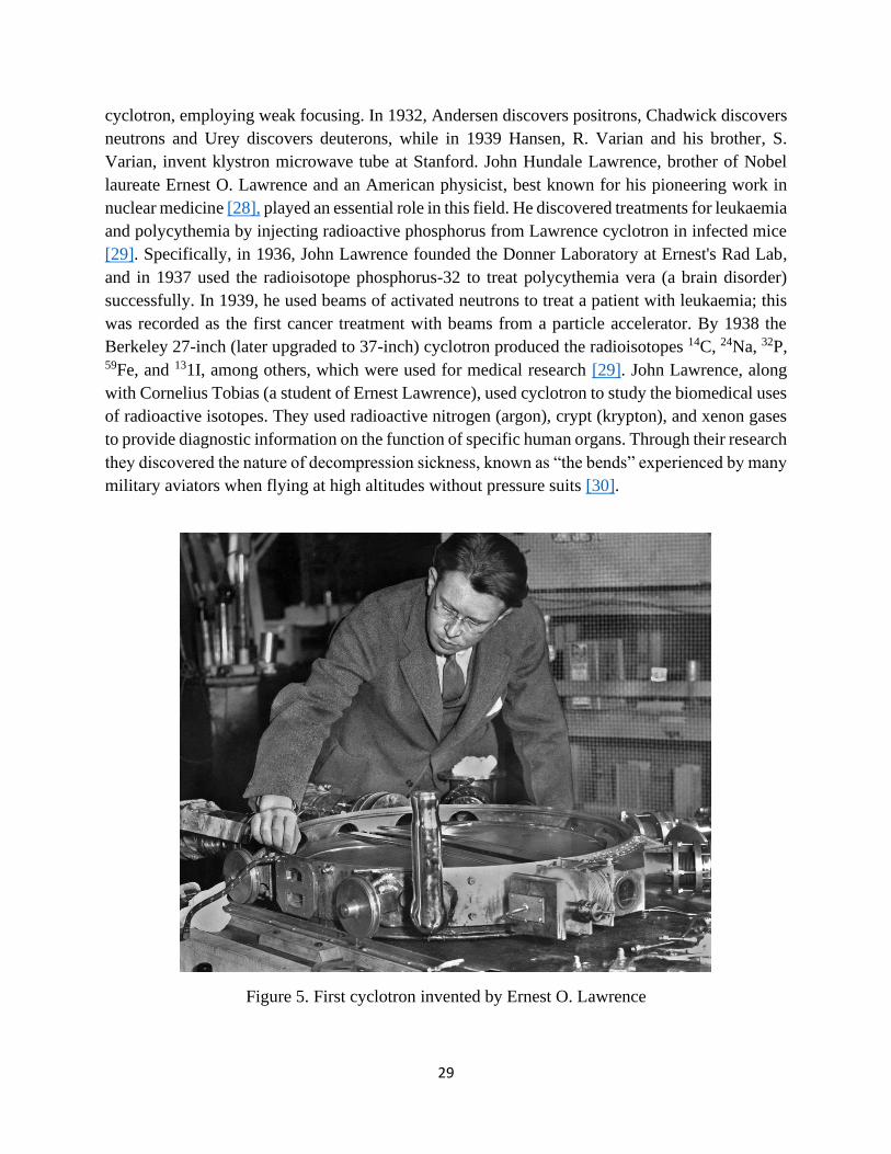
29
cyclotron, employing weak focusing. In 1932, Andersen discovers positrons, Chadwick discovers
neutrons and Urey discovers deuterons, while in 1939 Hansen, R. Varian and his brother, S.
Varian, invent klystron microwave tube at Stanford. John Hundale Lawrence, brother of Nobel
laureate Ernest O. Lawrence and an American physicist, best known for his pioneering work in
nuclear medicine [28], played an essential role in this field. He discovered treatments for leukaemia
and polycythemia by injecting radioactive phosphorus from Lawrence cyclotron in infected mice
[29]. Specifically, in 1936, John Lawrence founded the Donner Laboratory at Ernest's Rad Lab,
and in 1937 used the radioisotope phosphorus-32 to treat polycythemia vera (a brain disorder)
successfully. In 1939, he used beams of activated neutrons to treat a patient with leukaemia; this
was recorded as the first cancer treatment with beams from a particle accelerator. By 1938 the
Berkeley 27-inch (later upgraded to 37-inch) cyclotron produced the radioisotopes 14C, 24Na, 32P, 59Fe, and 131I, among others, which were used for medical research [29]. John Lawrence, along
with Cornelius Tobias (a student of Ernest Lawrence), used cyclotron to study the biomedical uses
of radioactive isotopes. They used radioactive nitrogen (argon), crypt (krypton), and xenon gases
to provide diagnostic information on the function of specific human organs. Through their research
they discovered the nature of decompression sickness, known as “the bends” experienced by many
military aviators when flying at high altitudes without pressure suits [30].
Figure 5. First cyclotron invented by Ernest O. Lawrence
30
In other activities, John Lawrence and Robert Stone were the first to use hadron therapy to
fight cancer, using the Crocker 60” cyclotron. They had begun clinical trials for neutron cancer
treatment (1938), just six years after Chadwick's (1932) discovery of the neutron. High-energy
neutrons damage and decompose materials over time. Neutron radiation damage is done primarily
by nuclear interactions, which have a high linear energy transfer (LET). Light LET radiation, such
as neutron radiation, is not recommended for tumour treatment, as the chances for a damaged
tumour cell to repair itself is very small (NIU Institute for Neutron Therapy at Fermilab). During
the World War II, any efforts on exploiting neutron radiation for cancer treatment were terminated,
as the cyclotrons were used for war purposes. Yet, after the war, a revived interest in neutron
therapy triggered clinical trials in the 1970’s, with the usage of accelerators other than cyclotrons
for most of the trials. By the 1980’s, neutron therapy was no longer used for routine cancer
treatment.
In the same year (1938), J. Chadwick published an article in Nature entitled “The Cyclotron
and Its Applications,” in which it is explicated that the induced nuclear transmutation from
accelerated particles has application in the biological sciences as a source of secondary particles
(neutrons in particular), as a labelling agent (tracer) and as a therapeutic in treating disease in
targeted areas of the body [11]. In 1941, the first cyclotron dedicated to the production of
radioisotopes was installed at Washington University, St. Louis, with funds provided by the
Rockefeller Foundation, and was used to produce isotopes of phosphorus, iron, arsenic and
sulphur. In the mid-1950s, a group at Hammersmith Hospital in London put into operation the first
hospital-based cyclotron, wholly dedicated to radionuclide production. Scanditronix was founded
in 1965 as a private company to commercialize cyclotrons for use in the medical field.
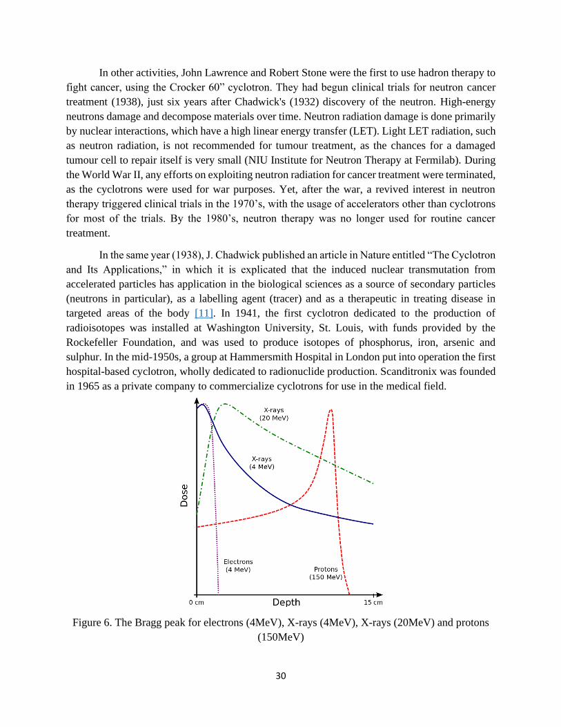
Figure 6. The Bragg peak for electrons (4MeV), X-rays (4MeV), X-rays (20MeV) and protons
(150MeV)

31
Robert Wilson, realizing the advantages of the hadron Bragg peak (Figure 6) (the Bragg
peak is a noticeable peak on the Bragg curve, which plots the energy loss of ionizing radiation
during its travel through matter), proposed the use of high-energy protons and other charged ions
to treat deep-seated tumours in the human body [31]. The basic physics principle underlying this
proposal, is the way in which the high energy ions lose energy while passing through matter.
Ionized (charged) particles loose energy slowly through atomic interactions, as they enter matter
until near the end of their range, where they lose ~85% of their energy [32]. The large energy loss
peak in Fig. 6 corresponds to the Bragg Peak.
Specifically, figure 6 illustrates the peak for proton (150MeV), X-rays (4MeV and 20MeV)
electrons (4MeV). The electrons and X-rays are highly penetrating and deliver a dose throughout
any volume of tissue irradiated. Electron beam is considered appropriate for targeting shallow
surfaces, such as a patient’s skin, while X-ray radiation is delivered a few centimetres from the
patient’s skin, depending on the energy it was initially given. It then gradually loses this energy
until it reaches the target. As tumours are almost always in-depth located, the photon actively
interacts with outer healthy cells and drops only a small remaining dose of ionizing radiation on
the deeper diseased cells. Moreover, both electrons and photons continue to emit radiation (exit
dose) after leaving patient’s tissue. In general, X-ray beam continues to travel past the tumour and
delivers radiation to the healthy tissues both anterior and posterior to the tumour. On the contrary,
the proton beam is easily controlled and delivers its maximum dose at a precise depth, which is
determined by its initial given energy (via acceleration). The absorbed dose increases very
gradually with greater depth and lower speed, suddenly rising to a peak when the proton is
ultimately stopped (Bragg peak). Immediately after this burst of energy, the proton completely
stops to irradiate.
Figure 7. The Accelerator Complex of the European Organization for Nuclear Research, CERN
[22]
32
Nowadays, the accelerated particles gain significant high energies (~TeV) inside the most
powerful acceleration systems. In these cases, the acceleration is achieved gradually by the use of
many kinds of accelerating systems. Figure 7 illustrates the cluster of accelerators at CERN, which
comprise different pre-acceleration stages, contributing to the world’s largest accelerator, the
Large Hadron Collider (LHC). The LHC is the largest and most powerful particle accelerator to
date. It consists of a 27-km ring of superconducting magnets with several accelerating structures
that enhance the energy of the particles along the road. This is currently operating at 6.5 TeV
energy while the maximum possible energy per beam is 7 TeV. The accelerated particles are sped
up in a series of interconnected linear and circular accelerators. Once they reach the maximum
speed that one part of the accelerator chain can achieve, they are shot into the next. More than 50
types of magnets are needed to send them along complex paths without their losing speed. All the
magnets in the LHC ring are electromagnets, which use a current of 11,080 amperes to produce
the magnetic field, and a superconducting coil allows the high currents to flow without losing
energy to electrical resistance (operate in superconducting mode). Therefore, the magnetic field
applied in the complex of circular accelerators of the LHC is generated in a different way compared
to the magnetic field applied in the entire plane of a classical cyclotron.
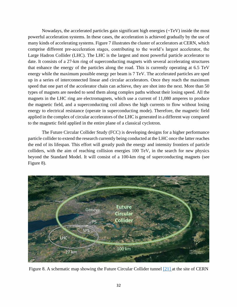
The Future Circular Collider Study (FCC) is developing designs for a higher performance
particle collider to extend the research currently being conducted at the LHC once the latter reaches
the end of its lifespan. This effort will greatly push the energy and intensity frontiers of particle
colliders, with the aim of reaching collision energies 100 TeV, in the search for new physics
beyond the Standard Model. It will consist of a 100-km ring of superconducting magnets (see
Figure 8).
Figure 8. A schematic map showing the Future Circular Collider tunnel [21] at the site of CERN
33
3.3. Parameters characterizing particle accelerators
The purpose of an accelerator of charged particles is to direct a beam of a specific kind of
particles of a chosen energy against a target. Particle accelerators operate by exploiting the way in
which electrically charged particles move in electric and magnetic fields. The electric fields
provide energy to the particles, accelerating them, while the magnetic fields divert the particles
and focus them into hundreds of beam bunches. Different arrangements of electric and magnetic
fields can be used which, together with the nature and mechanical arrangement of the (ring)tube
carrying the accelerated particles are forming different types of accelerators. All particle
accelerators have the same essential elements though: a particle source, systems with electric fields
or electromagnetic frequency cavities that accelerate the particles, injector systems, magnets
providing the fields for deflecting and focusing the particle beams and various monitoring systems
and detectors for observing the particles and their collisions. Necessary elements are also the
systems that provide the very low pressure in the accelerator tube (vacuum) and the stability of the
temperature (on some occasions cryogenic temperature is needed). Accelerators and colliders can
be characterised by all these factors as well as several technical characteristics that are described
below.
The performance of particle colliders is usually quantified by the beam energy and the
luminosity [18; 33]. In relation to the first, the energy of a particle as accelerated in the laboratory
is not always what is relevant in determining the threshold for initiating a particular elementary
particle process, nor the collision energy in the centre of mass frame of composite colliding
particles but the collision energy in the centre of mass of the colliding “elementary” constituent
particles. The centre of mass energy 𝐸𝑐𝑚 of two colliding particles of rest masses 𝑚1, 𝑚2, and
total energies 𝐸1, 𝐸2 respectively, is given by 𝐸𝑐𝑚 = 𝑝𝑖𝑝𝑖 where 𝑝𝑖 is the total four-moment of the
particles. For instance, if a proton of energy 𝐸1 = 𝛾𝑚1𝑐2 strikes a proton at rest, then 𝐸𝑐𝑚 =
√[2(𝛾 + 1)]𝑚1𝑐2. In the non-relativistic limit only one-half of the incident kinetic energy is
available while in the relativistic limit γ>>1 the centre of mass energy grows with the square root
of the energy of the incident protons. If two relativistic particles collide then 𝐸𝑐𝑚 = 2𝐸 if the
particles have identical energy. These relations demonstrate the energy advantage of colliding
beams. But as investigations extend to smaller dimensions, involving elementary particles, such
as quarks and leptons, determining the potential to initiate elementary particle collision processes
requires the collision energy in the centre of mass frame and not the laboratory beam energy neither
the collision energy in the centre of mass frame of composite colliding particles. This can be
explained with reference to the Fermi motion of quarks, which influences the nucleon-nucleon
collisions. In fact, the constituent quarks do not only have the motion of their composite particle,
example proton, but move also with the Fermi motion.
The instantaneous luminosity is another critical parameter [18; 33], beyond the maximum
particle acceleration energy. In the scattering theory and accelerator physics, instantaneous

34
luminosity (L) is the ratio of the number of events detected (dN) in a certain time (dt) to the
interaction cross-section (σ) for a certain reaction (channel) of interest.
𝐿 =1 𝑑𝑁
𝜎 𝑑𝑡
(25)
The equation that defines the instantaneous luminosity from the characteristics of the
colliding beams (see Figure 9) is given below.
𝐿 ∝ 𝐾𝑁1𝑁2∭∫ 𝜌1(𝑥, 𝑦, 𝑠, −𝑠𝑜
+∞
−∞
)𝜌2(𝑥, 𝑦, 𝑠, 𝑠𝑜)𝑑𝑥𝑑𝑦𝑑𝑠𝑑𝑠0 (26)
Where 𝑠0 = 𝑐𝑡 is the “time” variable and 𝐾 = √(𝑢1⃗⃗⃗⃗ − 𝑢2⃗⃗⃗⃗ )2 − (𝑢1⃗⃗⃗⃗ 𝑥 𝑢2⃗⃗⃗⃗ )2/𝑐2 is the
kinematic factor.
Figure 9. Collider luminosity (per bunch crossing)
The instantaneous luminosity determines the events rate per reaction and has the
dimensions of events per time per area; it is usually expressed in cm-2 𝑠−1. In practice, L is
dependent on the particle beam parameters, such as beam width and particle flow rate, as well as
the target properties, such as target size and density [34]. It is provided by the following equation
as well:
𝐿 = 𝑁𝑜𝑛𝑡 [𝑠−1𝑐𝑚−2] (27)
Where: 𝑁𝑜 number of incident particles per unit of time, 𝑛𝑡 number of target particles per
unit area.

35
𝑛𝑡 =𝑁𝑡𝑆=𝜌𝑑𝑁𝐴𝐴
(28)
Where: S the frontal surface of the target, ρ density of the target, d thickness of the target,
𝑁𝐴 is the Avogadro number (6.023 * 1023) and A is the surface unit. The total number of scattered
particles (N) can be also calculated as follows:
𝛮 = 𝐿𝜎 = 𝑁𝑜𝑛𝑡𝜎 = 𝛷𝑜𝛮𝑡𝜎 (29)
𝛷𝑜 = 𝑁𝑜 𝑆⁄
the flux of the incident particles [𝑠−1𝑐𝑚−2].
(30)
Therefore, along with the energy parameter, the instantaneous luminosity determines
whether a specific reaction channel from the collisions in an accelerator is feasible or not.
In the case of two colliding beams of particles the formula becomes more complicated and
is given below.
𝐿 ∝ 2𝑁1𝑁2𝑓𝑛𝑏∭∫ 𝑑𝑥𝑑𝑦𝑑𝑠𝑑𝑠0 𝜌1𝑥(𝑥)𝜌1𝑦(𝑦)𝜌1𝑠(𝑠+∞
−∞
− 𝑠𝑜)𝜌2𝑥(𝑥)𝜌2𝑦(𝑦)𝜌2𝑠(𝑠 + 𝑠𝑜)
(31)
For high momentum transfer events, the cross section varies inversely as the square of the
momentum transferred. Therefore, the luminosity of colliders should increase quadratically with
energy in order to yield a constant data rate for “interesting” or novel events.
A related quantity is integrated luminosity (𝐿𝑖𝑛𝑡𝑒𝑔𝑟), the integral of the luminosity with
respect to time, with measurement units [𝑐𝑚−2].
𝐿𝑖𝑛𝑡𝑒𝑔𝑟 = ∫ 𝐿(𝑡′) 𝑑𝑡′𝑇
0
(32)
𝐿𝑖𝑛𝑡𝑒𝑔𝑟 directly relates to the number of observed events over a certain time, the total
number of interactions (not per second):
𝐿𝑖𝑛𝑡𝑒𝑔𝑟 𝜎𝑝 = 𝑛𝑢𝑚𝑏𝑒𝑟 𝑜𝑓 𝑒𝑣𝑒𝑛𝑡𝑠 𝑜𝑓 𝑖𝑛𝑡𝑒𝑟𝑒𝑠𝑡 (33)
The instantaneous luminosity (𝐿) and integrated luminosity (𝐿𝑖𝑛𝑡𝑒𝑔𝑟) are useful values to
characterize the performance of a particle accelerator. All collider experiments aim to maximize
their integrated luminosities, as the higher the integrated luminosity, the more data is available to
analyse. Yet, even though the number of events produced is given by eq. 30, the number of detected
events are calculated following a multiplication of the number of produced events the geometrical
acceptance of the detector, times the efficiency of the analysis algorithm for the particular reaction
searched for.

36
The channel performance coefficient is provided by the following equation:
𝑐𝑜𝑒𝑓𝑓𝑖𝑐𝑖𝑒𝑛𝑡 = 𝐿𝜎𝐸 (34)
Where, 𝐿 luminosity, 𝜎 total cross section of the channel of interest, and E is a
dimensionless quantity, a number smaller than 1 and is calculated as follows.
𝐸 = 𝐸1 ∗ 𝐸2 (35)
Where, Ε1: geometric acceptance (the total percentage of events emitted in the solid angle
of the detector), Ε2: efficiency of the analysis algorithm selecting the events in the channel.
Detector systems are of course also encountered in the process of running experiments in
accelerators, accomplishing particle tracking, momentum measurement of charged particles,
particle identification and energy measurement (total or partial) of single particles or groups of
particles (showers, jets). On-line and off-line data analysis is then performed. Detector systems
have over the years grown in geometric acceptance and their measurement energy and momentum
resolutions improved to maximize information from each event, improve the accuracy of
reconstruction and optimally use a collider’s luminosity. The efficiency of such detectors (see
equation 35), as stated above, is derived from the multiplication of geometric acceptance and the
efficiency of the selection algorithm [35].
In addition, other parameters are of relevance to the experimenter, such as the intensity of
the current circulating the beams, the number of beam bunches, the frequency of their collisions,
and the background, that is events coming from channels other than those under investigation.
3.4. Types of particle accelerators
This section focuses on different types of particle accelerators that exist nowadays. Particle
accelerators come in many forms, applying a variety of technical principles. They are based on the
type of interaction of the projectile particle(s) with static and dynamic electromagnetic fields and
it is the technical realization of these interactions that leads to the different types of particle
accelerators. One of the primary divisions of accelerators in categories relies on the time
dependence of the electric acceleration field. In this manner, particle accelerators are divided into
constant electric field (DC) accelerators and alternating electric field (AC) accelerators. Another
categorization of accelerators is established on how the particles collide. In linacs, particles are
held in a straight line, passing through successive electric fields, thereby increasing their energy
as they pass from one to the other. In circular accelerators (e.g., cyclotrons or synchrotrons),
particles are driven by magnetic fields in a circular orbit and thus pass through the same electric
field that is constantly accelerating them. The most energetic collisions occur when two bunches
of particles meet in front to front collisions. Most colliding particle accelerators are circular
machines in which the particles collide frontally with their antiparticles. They take advantage of
the fact that the particles and their antiparticles annihilate upon colliding to each other, thus

37
maximising the energy available for the collision products and facilitating the reconstruction of
events in the laboratory (centre of mass) frame and the production of heavier particles.
3.4.1. Principles of Linear Accelerators
In linear accelerators the particles are accelerated along a straight path by either
electrostatic fields or microwave electromagnetic fields (radiofrequency cavities). In accelerator
physics all forces on charged particles originate from electromagnetic fields. The nature of the
electric field can be static, pulsed, generated by a time varying magnetic field or a microwave field;
in all cases the field is responsible for the presence of a Lorentz force. The electric field is generated
by appropriate sources connected to an accelerating section. Electro-static fields emerge from the
existence of two electrodes with the particle source at the potential of one electrode and a hole in
the centre of the other electrode to let the accelerated particles pass through. Special resonant
cavities are used as accelerating sections with two holes on the axis of the cavity to let the beam
pass through [19]. The electric field can be represented by the plane wave equation:
𝐸(𝜓) = 𝛦𝜊𝑒𝑖(𝜔𝑡−𝑘𝑠) = 𝛦𝜊𝑒
𝑖𝜓 (36)
where 𝜔 is the frequency and 𝑘 the wave number, including the case of static fields with
𝜔 = 0 and 𝑘 = 0. The Lorentz force acting on an electric charge is:
𝐹𝐿 =𝑑𝑝
𝑑𝑡=𝑑
𝑑𝑡(𝑚𝑐𝛾𝛽) = 𝑒𝐸(𝜓)
(37)
and the equation of motion for particles under this force is:
𝑑
𝑑𝑡(𝑚𝑐𝛾𝛽) = 𝑒𝐸(𝜓)
(38)
Integration of the above results in an expression for the momentum gain of the particle,
which gives:
𝛥𝑝 = 𝑚𝑐(𝛾𝛽 − 𝛾𝜊𝛽𝜊) = 𝑒∫𝐸(𝜓)𝑑𝑡 (39)
where 𝑚𝑐𝛾𝜊𝛽𝜊 is the initial momentum of the particle. However, it is complicated to
perform a time integration which requires the tracking of each particle through the accelerating
cavity. For that reason and for simplicity, we look for the gain in kinetic energy, which reduces to
a spatial integration of the electric field in the accelerating cavity. This integral is a property of the
cavity and is independent of the particle motion. With 𝛽𝛥𝑐𝑝 = 𝛥𝛦𝑘𝑖𝑛 the energy gain for particles
passing through the accelerating section is:
𝛥𝛦𝑘𝑖𝑛 = 𝑒∫ 𝐸(𝜓) 𝑑𝑠𝐿𝑐𝑦
(40)
where 𝐿𝑐𝑦 is the length of the accelerating section.
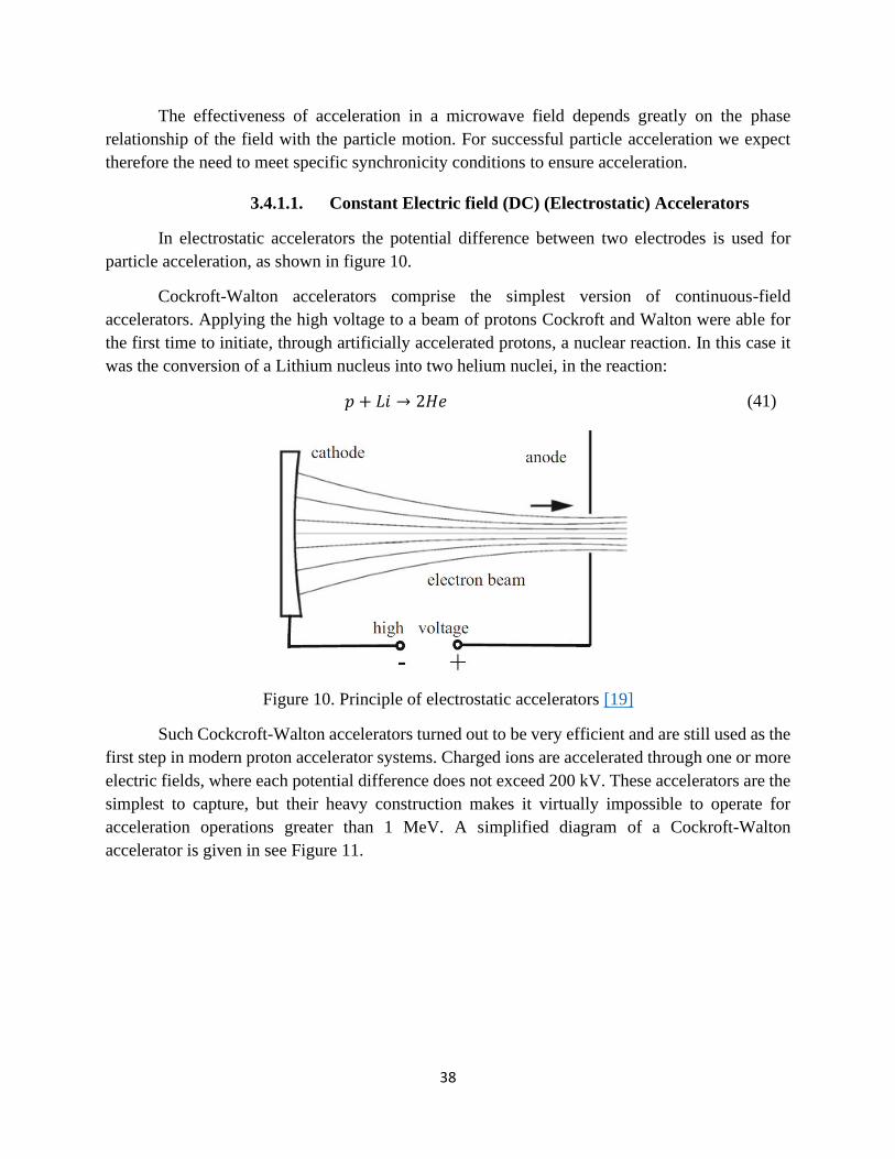
38
The effectiveness of acceleration in a microwave field depends greatly on the phase
relationship of the field with the particle motion. For successful particle acceleration we expect
therefore the need to meet specific synchronicity conditions to ensure acceleration.
3.4.1.1. Constant Electric field (DC) (Electrostatic) Accelerators
In electrostatic accelerators the potential difference between two electrodes is used for
particle acceleration, as shown in figure 10.
Cockroft-Walton accelerators comprise the simplest version of continuous-field
accelerators. Applying the high voltage to a beam of protons Cockroft and Walton were able for
the first time to initiate, through artificially accelerated protons, a nuclear reaction. In this case it
was the conversion of a Lithium nucleus into two helium nuclei, in the reaction:
𝑝 + 𝐿𝑖 → 2𝐻𝑒 (41)
Figure 10. Principle of electrostatic accelerators [19]
Such Cockcroft-Walton accelerators turned out to be very efficient and are still used as the
first step in modern proton accelerator systems. Charged ions are accelerated through one or more
electric fields, where each potential difference does not exceed 200 kV. These accelerators are the
simplest to capture, but their heavy construction makes it virtually impossible to operate for
acceleration operations greater than 1 MeV. A simplified diagram of a Cockroft-Walton
accelerator is given in see Figure 11.

39
Figure 11. Diagram of a Cockroft-Walton accelerator
Much higher voltages can be reached with a Van de Graaff accelerator, which is the most
common form of continuous electric field accelerator. In this case, the potential difference is
caused by a mechanical load (belt) transfer. The ions exit the ion source and accelerate by a
continuous electric field along a tube (in a vacuum) where a series of metal plates gradually
increase the voltage. The most popular form of accelerator Van de Graaff is Tandem Van de Graaff
(see Figure 12).
Figure 12. Diagram of a Tandem Van de Graaff accelerator
In the above accelerator the ions accelerate twice using the same field. At the beginning,
negatively charged ions accelerate to the centre of the accelerator - which is positively charged.
There, through a thin film, they are stripped entirely or partially by electrons, thereby converting
them into positively charged ions, which are then accelerated once more by the positive charge in
the centre of the accelerator.

40
3.4.1.2. Alternating electric field (AC) accelerators
The simplest version of alternating current electric field accelerators are the linear
accelerators. As in all previous cases, the ions enter the accelerator. In linear accelerators, the beam
ions accelerate between the sliding cavities. A negatively charged ion accelerates between the first
and the second cavity, while the Figure 13 shows the acceleration of the ion between the second
and third cavities. This is only achieved if the field changes harmoniously and this happens when
the length of the cavities gradually increases. As the ions accelerate, the length of each cavity is
gradually increased, so that the ion is leaving the cavity when the field has that direction leading
to an increase of its kinetic energy.
The operating frequencies of the linear accelerators are in the order of MHz; therefore,
such accelerators are also called linear radiofrequency (RF) accelerators. In the case of these
accelerators, there is no continuous ion flow from the beam, but a pulse instead. Therefore, very
high accelerating voltages can be achieved in resonant rf cavities far exceeding those obtainable
in electrostatic accelerators of similar dimensions. Another type of alternating current electric field
(AC) accelerator is the cyclotron which falls under the category of circular accelerators, hence
discussed further below.
Figure 13. Graphical illustration of a linear accelerator and its operation principle (here: Alvarez
Linac -drift tube linac, 1940s)
3.4.2. Principles of Circular Accelerators
Technical limitations for linear accelerators (e.g., electrostatic, and linear RF accelerators)
encountered in the early 1920s to produce high-power rf waves stimulated the search for alternative
accelerating methods or ideas for accelerators that would use whatever little rf fields could be
produced as efficiently as possible. Circular accelerators are based on the use of magnetic fields

41
to guide the charged particles along a closed orbit. The acceleration in circular accelerators is
achieved in one or few accelerating cavities which are traversed by the particle beam many times
during their orbiting motion. This simplifies the RF system compared to the large number of energy
sources and accelerating sections required in a linear accelerator. However, while this approach
seemed to be the most appropriate to produce high energy particle beams, its progress soon became
limited for the acceleration of electrons by copious production of synchrotron radiation2 [19]. For
this reason, the principle of circular accelerators as when applied for electrons has reached a
technical and economic limit at about 300 GeV due to synchrotron radiation losses, which makes
it increasingly harder to accelerate electrons to higher energies [36]. Further progress in the attempt
to reach higher electron energies is being pursued through the principle of linear colliders where
synchrotron radiation is avoided [37].
The simplicity of circular accelerators and the absence of significant synchrotron radiation
for protons and heavier particles, like ions, has made circular accelerators the most successful and
affordable mechanism to reach the highest possible proton energies for fundamental research in
high energy physics. Protons are being accelerated into the TeV range in the Large Hadron Collider
(LHC) at CERN in Geneva, Switzerland.
In conclusion, the basic principle underlying the operation of cyclotrons is similar as in
linear accelerators, where through an appropriate alternation of the electric field, the particles
accelerate in the gap between two electrodes or metallic chambers containing an electromagnetic
field known as radiofrequency (RF) cavities. Charged particles injected into this field receive an
electrical impulse that accelerates them. Then, the field in the RF cavities is made to oscillate
(switch direction) at a given frequency. An additional magnetic field, perpendicular to the plane
of the ions’ track, bends them, forcing them to execute circular motion. In other words, a magnetic
field guides the ions in circular paths, while an electric field accelerates them [16]. More
information about the cyclotron, its functionalities and produced radioisotopes are given in the
sections that follow.
3.5. Applications of particle accelerators
Particle accelerators were originally developed for research purposes. The first discoveries
on the basic structure of matter were made in experiments with cosmic rays and radioactivity,
which explored the collisions of subatomic particles, electrons, protons, and heavier atomic nuclei.
Since then, particle accelerators have allowed physicists to study particle collisions in more
controlled conditions and helped uncover most of the material particles and forces carriers we
know today. Today the use of accelerators in the field of basic research is widespread. Particularly
in high-energy physics, increasingly powerful accelerating devices are used to produce and study
2 Synchrotron radiation is the name given to the radiation which occurs when charged particles are accelerated in a
curved path or orbit.

42
new particles. In nuclear physics, the study of its core dynamics and its structure is now based on
the use of the accelerator. Apart from the applications of accelerators in nuclear physics and high-
energy physics, their use in the study of the microcosm and the structure of matter is also
widespread, and there are few examples of accelerators for medical applications (e.g., production
of radioisotopes, cancer therapy - X rays, radiotherapy, hadron therapy - equipment sterilization)
[32], archaeometry applications, non-destructive stoichiometric methods, and industrial use. For
cyclotrons in particular, a large field of applications relates to the utilization of accelerated particles
to bombard targets in order to produce radioisotopes [38]. The medical and industrial applications
eventually have led to the commercial construction of cyclotrons in addition to carrying out
scientific research. In relation to medical applications, the first manufactured cyclotrons, the so-
called Lawrence cyclotrons, can produce medical radioisotopes for the treatment of cancer. The
functionality of cyclotrons and more information on different types of cyclotrons are given in the
sections that follows.
3.6. The Cyclotron
A cyclotron is a particle accelerator that is used for the production of short-lived radioactive
isotopes. Cyclotron can accelerate ions, such as protons or deuterons (H+, H-, 𝐻2+ ions), as well as
highly charged heavy ions to ~ 1 mA, while H+, H- to ~few mA. Accelerated particles (such as
hydrogen atoms) at very high speeds hit on a target substance where a reaction takes place that
produces a radioactive element. Both the accelerated particles and target substances are
specifically chosen to produce the desired radioactive element. Once produced in the cyclotron,
the radioactive material (e.g. 18F) is transferred to a shielded “hot cell” where it is run through
sophisticated chemistry modules to produce biological tracers (e.g. FDG).
For instance, in the (p, n) reaction a 17.5 MeV proton beam and a target of 18O enriched
water are utilized to produce 18F, following the reaction: 𝑂 + 𝑝11
818 → 𝐹 + 𝑛0
1918 + 𝛾. Then, 18F is
attached to 2-deoxyglucose, resulting to the product 18F-Fluorodeoxyglugose (18F-FDG). Tracers,
such as the 18F-FDG, can be used in medical imaging to diagnose and manage a disease (e.g. a
malignant tumour) more accurately. Therefore, a prominent area of application of cyclotrons
involves the production of short-lived neutron deficient radiotracers for use in emission
tomography, especially PET-CT and SPECT scan systems. Cyclotrons are used to produce longer-
lived isotopes for therapeutic procedures as well as for other industrial and applied science
applications. Another area of application of cyclotrons includes the so-called proton therapy. In
this case, the protons accelerate to high speeds and exit the cyclotron with the aim to target directly
a malignant tumour. Proton beams can be then conformed and controlled easily and precisely.

43
Figure 14. Graphic representation of the cyclotron’s basic function [39]
In particular, the cyclotron consists of a vacuum chamber into which the charged particles/
ions are injected into the centre (see green dot in Figure 14). The cyclotron principle employs a
uniform magnetic field and an RF cavity that extends over the whole apperture of the magnet. The
particles are accelerated by a high frequency alternating voltage applied between two D-shaped
electrodes and follow a circular path. Because of the resemblance of this semi-circular structure
with the capital D, the electrodes have been called “dees” [16]. Nowadays, cyclotrons can
accommodate more than two dees, achieving higher energies for the particles with smaller required
dimensions for the cyclotron. For the sake of the description here I refer to two dees. These dees
are connected to terminals of an alternating voltage source, an oscillator. This is needed for
changing the polarity among the two dees. Two electromagnets are also placed above and below
the two dees, creating a magnetic field perpendicular to the direction of the electric field. This
entire arrangement is sealed in a vacuum box. Therefore, the two dees create the electric field, the
direction of which is horizontal, while the direction of the magnetic field is vertical. When a
positively charged particle is placed (e.g., proton), maintaining a constant frequency in the
alternating current source, the particles accelerate each time they pass through the gap between the
two semicircle electrodes, as they receive Coulomb forces (𝐹 = 𝑞�⃗� ) from the electric field
between the dees. Because of the force applied the particles get acceleration that equals to 𝑎 =
𝑞�⃗� /𝑚 and, due to this acceleration, the speed of the particle increases each time it passes from
one dee to the other. When the particle accelerates for the first time and enters one of the dees, this
is an enclosed container, hence �⃗� = 0, then 𝐹 𝑒𝑙 = 0. However, the presence of the magnetic field
makes the particle to move perpendicular to its direction, due to the Lorentz force applied (see
Figure 15).

44
Figure 15. The electric and magnetic field of a cyclotron
𝐹 𝐿𝑜𝑟 provides the centripetal force and makes the charged particle move along a circular
path of radius 𝑅 = 𝑚𝑉/𝑞𝐵. The particle makes a semi-circle and comes to the gap once more in
𝑡 = 𝑇/2. In other words, the presence of a static magnetic field forces the particles to move into a
spiral pattern from the centre of the vacuum chamber to the outside. As soon as the polarity of the
two dees has changed, the particle enters the gap once more, experiencing Coulomb forces which
accelerate the particle once more. The same procedure repeats. The next time the particle will leave
the one dee and enter the other, it will make a greater semi-circle because of its increased velocity.
As the energy of the accelerating particle increases, the radius of its circular orbit also increases.
This significantly limits the use of cyclotrons for the manufacture of powerful accelerators.
Therefore, the accelerated ions experience forces due to the simultaneous presence of an electric
and magnetic field, forcing them to follow a spiral path (see Figure 16). As the particles’ spiral
path leads them to the edge of the cyclotron, the particles eventually enter the bombardment
chamber and interact with the target to produce the radioisotopes. With such high velocity, the
particle has high energy, and it hits the target.
Figure 16. The spiral path of a proton in a cyclotron

45
The principle of the cyclotron is limited to nonrelativistic particles (see section: 1.4 A
charge in an electric and magnetic field). In brief, the basic physics principles applied in the
cyclotron operation are given below: For nonrelativistic particles, the centripetal force 𝐹𝑐 required
to keep them in their curved path is given by equation (16) (𝐹𝑐 = 𝑚𝑢2 𝑟⁄ ), where 𝑚 is the particle's
mass, 𝑢 its velocity, and 𝑟 the radius of the path. This force is provided by the Lorentz force 𝐹𝐵 of
the magnetic field 𝐵.
𝐹𝐵 = quB (42)
where q is the particle’s charge. The particles reach their maximum energy at the periphery
of the dees, where the radius of their path is 𝑟 = 𝑅 ,the radius of the dees. Equating these two
forces it yields:
𝑚𝑢2
R= 𝑞𝑢𝐵
(43)
𝑢 =𝑞𝐵𝑅
𝑚
(44)
Protons are sufficiently nonrelativistic up to kinetic energies of about 20–25MeV. If
particles do not reach relativistic energies, the maximum achievable kinetic energy 𝛦𝑘𝑖𝑛 depends
on the type of the particle, the magnetic field 𝐵, which is limited to about 2 T for ferromagnetic
electromagnets, and the radius of the dees 𝑅, which is determined by the diameter of the magnet’s
pole pieces. Therefore, the output energy of the particles is:
𝐸𝑘𝑖𝑛 =1
2𝑚𝑢2 =
(𝑐𝑝)2
2𝑚𝑐2=𝑍2𝑒2𝐵𝑦
2𝑅2
2𝑚𝑐2
(45)
where Z stands for the charge multiplicity of the particles.
Therefore, the limit to the cyclotron's output energy for a given type of particle is the
strength of the magnetic field. Very large magnets have been constructed for cyclotrons,
culminating in Lawrence’s 1946 synchrocyclotron, which had pole pieces 4.67 m in diameter.
In the non-relativistic approximation, the cyclotron frequency does not depend upon the
particle’s speed or the radius of the particle’s orbit. As the beam spirals outward, the rotation
frequency stays constant, and the beam continues to accelerate as it travels a greater distance in
the same time period. In contrast to this approximation, as particles approach the speed of light,
the cyclotron frequency decreases proportionally to the particle’s Lorentz factor. Acceleration of
relativistic particles therefore requires either modification of the frequency during the acceleration,
leading to the synchrocyclotron, or modification to the magnetic field during the acceleration,
which leads to the isochronous cyclotron. Those cyclotron variations are discussed further below
in section 3.7 Different types of cyclotrons.

46
Apart from the operation principles presented above, essential to consider are other
components of the cyclotron systems (see Figure 17). The primary components of cyclotrons are
the magnetic system, vacuum-sealed dee chambers, the oscillating power system, the ion source
and injector, the shielding, and the focusing equipment.
Figure 17. A simplified cross-section and plan view of a ‘classical’ cyclotron [40]
First, an ion source is required, as illustrated in the figure above. The cyclotron ion source
has the responsibility for producing well collimated intense beams of various charge states of many
atomic species, polarized and unpolarized [41]. The first sources were “internal sources”, designed
to fit within the few centimetres of space inside the first orbit of acceleration in the central region.
With the development of more advanced sources of heavy and polarized ions, a space of 1 m3 or
more was required for the source, so it had to be placed outside the cyclotron as an “external
source”. Injection systems have been developed to transport the beam to the cyclotron centre
region, either axially or radially. To create positively charged ions, one or more electrons must be
removed from atoms and ions, which requires energy. This energy can be supplied by a
bombarding electron, by a heated surface of high work function, by a very high electric field or by
a photon. For the production of positive ion beams by electron bombardment, electrons of energy
greater than the ionization potential bombard the molecules and ions in a plasma. In the early
1930’s the first cyclotrons of Lawrence used a hot filament ion source with a hydrogen gas feed to
produce protons in an open arc. For heavier ions of high charge state, the filament source had to
be improved. In the 1950’s the filament was replaced by a solid cathode button, the reflector was
connected to the cathode and more arc power was provided. The resulting source is called the PIG
source, from Penning Ion Gauge or Philips Ion Gauge [41]. Several other types of positive ion

47
sources are used for external injection of light ions. For instance, a multi-cusp ion source is used
widely in H− cyclotrons, designed to have cusp geometries of magnetic field inside the ion source
chamber, where ions are confined and enhanced plasma densities [42].
Second, as mentioned earlier, two copper D-shaped electrodes, referred to as “dees,” are
located perpendicularly between the two large magnets. The dees faced opposite one another
forming a circle bisected by a narrow gap. Then, an oscillator supplies oscillating radio frequency
(RF) power to the gap. The dees are contained inside a vacuum chamber supported by several
pumps and a refrigeration system and has moveable panels that permit tuning the system. Also,
the choice of the pole shape and the number of sectors have a great impact on the available space
for RF systems. Dees, and possibly stems and liners must fit into the gaps and/or valley sections.
Figure 18 illustrates different pole shapes, in case of ‘Azimuthally Varying Field Isochronous
Cyclotron’, or AVF isochronous cyclotron3.
Figure 18. Different pole shapes for AVF isochronous cyclotrons [40]
Once the accelerated particles reach the outer edge of the dees, they are shot off into the
beam deflector and out the exit window at high velocity. The deflector consists of two arc-shaped
pieces parallel to one another to guide the particle beam out. Operators in the control room can
then adjust the angle of the deflector to improve the quality of the beam.
The external beam equipment originally consisted of four components—the shield tube,
focusing magnets, a beam-shaping diaphragm, and a deflector magnet. The beam emerging from
the deflector horizontally travels through a shield tube to prevent the cyclotron’s electric field from
affecting the magnets. A chamber at the end of the tube contains a carbon disk to concentrate the
beam. The beam is further concentrated as it passes through a vacuum-sealed diaphragm. The
deflector magnet originally bent the beam horizontally at a 45° angle toward a target room. This
3 As explicated latter in section 3.11 Different types of cyclotrons, when the particle energies exceed a few MeV, 𝑚 =𝑚𝑜 no longer holds, and thus the particles have relativistic kinetic energies. To compensate for the increasing mass
(causing loss of isochronism), B was increased with radius. This however, results in axial defocusing. To compensate
for that effect, the so-called ‘flutter’ is introduced. It consists of adding a suitable azimuthal modulation to the magnetic
field, to compensate for the axial defocussing effect of the radially increasing B. Such a machine is called an AVF
isochronous cyclotron.

48
equipment has been frequently modified and expanded over the years. The beam shutter target is
a copper shutter used to fine tune the beam just before it impacts the intended target.
As for the target areas, the cyclotron originally possessed two target assembly plates. One
supported a channel and the other a foil window. The latter included three thin aluminium frames
that allowed the beam pass through to hit the intended target. Later, a vacuum-sealed target
chamber was installed in the vault room wall to facilitate the adjustment of target equipment
without disrupting the environment within the vault. The facility utilizes radiation monitors in the
vault room and hallways to track radiation levels [43].
Last, but not least, radiation shielding is an important design component of cyclotrons.
Efficient radiation shielding is very important for safe cyclotrons which are used for medical
applications for both producing large activities of short-lived radioisotopes and for proton therapy
[44]. For proton accelerators, only neutron is considered for the shielding wall, because photon is
much easier to shield than neutron and dose rate contributions outside the shielding wall from other
secondary particles can be ignored [44]. A self-shielded cyclotron can reduce neutron and gamma
activity levels outside the shielding to safe levels. Unshielded cyclotrons, which are often preferred
by experienced cyclotron personnel due to easier repair and maintenance required, are housed in
dedicated concrete vaults [45]. To avoid unnecessary activation of the concrete shielding of the
bombardment vault, additional shielding around the target itself could be installed. In this case,
‘sandwich’ shielding consisting of an inner iron layer followed by a wax layer containing boron
compounds and finally a lead layer is considered necessary.
In addition to the above components, certain technical specifications should be
encountered. First, the beam energy is an important parameter in designing a cyclotron, as it
determines the size, the cost, and the usefulness of the machine. Second, the beam intensity affects
the yielding of isotopes, but the maximum intensity that can be used is strictly limited by power
dissipation in the target. Third, radiation biology requires a good energy resolution to be able to
obtain a well-defined Bragg Peak, even though energy resolution can be unimportant for
radioisotopes production. Then, energy and particle variability are other specifications considered.
For isotopes production it is not essential to vary the machine energy although this capability can
offer advantages. Maximum energy is generally used to obtain a maximum yield. Degradations of
energy can be carried out by using absorber foils, as good energy resolution is not required,
although beam current would then probably be limited by heating of the absorber foils rather than
by target heating. Most compact cyclotrons can accelerate p, d, 3He and 4He which are considered
adequate for isotope production. However, accelerated beams of heavier particles would be of
great use in radiation biology and nuclear physics [46].
3.7. Different types of Cyclotrons
Cyclotrons have been developed and evolved with the advancement of technology, giving
more advanced versions of the first cyclotron, such as synchrocyclotrons (precursors of
synchrotrons). Nowadays, cyclotrons exist in different forms: classical (as described above),

49
isochronous, synchrocyclotrons and synchrotrons. Brief information is provided for each one of
the above-mentioned cyclotron types.
As explicated above, in cyclotrons the accelerated particles’ velocity is given by equation
(44). From that, derives that the period of the particles’ motion is constant, given by equation (46)
and the frequency by equation (47).
𝑇 =2𝜋𝑅
𝑢=2𝜋𝑚
𝑞𝐵
(46)
f =qB
2𝜋𝑚
(47)
Therefore, even though the radius of the charged particle is increasing, and likewise the
velocity of the particle is increasing at each step, the frequency of revolution remains constant. In
that case, the oscillator must have a frequency which is exactly equal to the frequency of revolution
of the charged particle; only then, both the charged particles’ motion and the oscillating potential’s
wave will be in phase and every time the charged particle is in the gap between the 2 dees, it will
experience a positive acceleration. Thereby, the velocity of the particle is increasing each time it
passes from the one dee to the other, reaching high velocity. This is effectively the working
mechanism of a classical cyclotron.
However, when the velocity of the charged particle becomes very high, and thus the kinetic
energy of the particle becomes relativistic, the mass of the particle does no longer equal the mass
in rest (eq. 48).
𝑚 =𝑚𝑜
√1 −𝑢2
𝑐2
(48)
Thus, the mass of the charged particle does not remain constant, and neither is the
frequency of revolution (eq. 49).
𝑓 =𝑞𝐵
2𝜋𝑚𝑜√1 −
𝑢2
𝑐2
(49)
As the particle accelerates, its mass starts to increase and the frequency to decrease.
Therefore, there is a relativistic decrease in the frequency of the revolution of the charged particle.
As a result the frequency of the particle’s revolution and the frequency of the oscillator go out of
phase, which does not allow the charged particle to accelerate each time it passes from the one dee
to the other. This barrier is trounced with the introduction of a synchrotron. In particular, the
problem can be fixed by either varying the frequency of the oscillating potential or by varying the
magnetic field such that the two frequencies remain in phase.
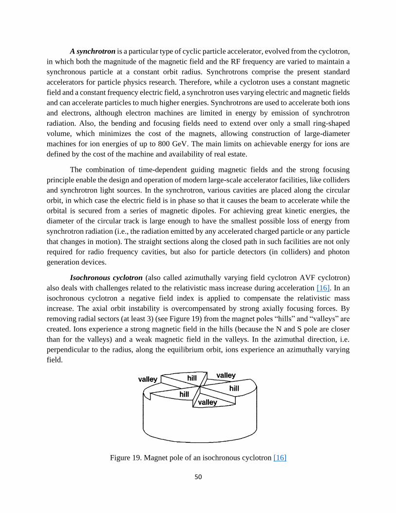
50
A synchrotron is a particular type of cyclic particle accelerator, evolved from the cyclotron,
in which both the magnitude of the magnetic field and the RF frequency are varied to maintain a
synchronous particle at a constant orbit radius. Synchrotrons comprise the present standard
accelerators for particle physics research. Therefore, while a cyclotron uses a constant magnetic
field and a constant frequency electric field, a synchrotron uses varying electric and magnetic fields
and can accelerate particles to much higher energies. Synchrotrons are used to accelerate both ions
and electrons, although electron machines are limited in energy by emission of synchrotron
radiation. Also, the bending and focusing fields need to extend over only a small ring-shaped
volume, which minimizes the cost of the magnets, allowing construction of large-diameter
machines for ion energies of up to 800 GeV. The main limits on achievable energy for ions are
defined by the cost of the machine and availability of real estate.
The combination of time-dependent guiding magnetic fields and the strong focusing
principle enable the design and operation of modern large-scale accelerator facilities, like colliders
and synchrotron light sources. In the synchrotron, various cavities are placed along the circular
orbit, in which case the electric field is in phase so that it causes the beam to accelerate while the
orbital is secured from a series of magnetic dipoles. For achieving great kinetic energies, the
diameter of the circular track is large enough to have the smallest possible loss of energy from
synchrotron radiation (i.e., the radiation emitted by any accelerated charged particle or any particle
that changes in motion). The straight sections along the closed path in such facilities are not only
required for radio frequency cavities, but also for particle detectors (in colliders) and photon
generation devices.
Isochronous cyclotron (also called azimuthally varying field cyclotron AVF cyclotron)
also deals with challenges related to the relativistic mass increase during acceleration [16]. In an
isochronous cyclotron a negative field index is applied to compensate the relativistic mass
increase. The axial orbit instability is overcompensated by strong axially focusing forces. By
removing radial sectors (at least 3) (see Figure 19) from the magnet poles “hills” and “valleys” are
created. Ions experience a strong magnetic field in the hills (because the N and S pole are closer
than for the valleys) and a weak magnetic field in the valleys. In the azimuthal direction, i.e.
perpendicular to the radius, along the equilibrium orbit, ions experience an azimuthally varying
field.
Figure 19. Magnet pole of an isochronous cyclotron [16]
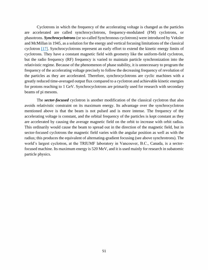
51
Cyclotrons in which the frequency of the accelerating voltage is changed as the particles
are accelerated are called synchrocyclotrons, frequency-modulated (FM) cyclotrons, or
phasotrons. Synchrocyclotrons (or so-called Synchronous cyclotrons) were introduced by Veksler
and McMillan in 1945, as a solution for the energy and vertical focusing limitations of the classical
cyclotron [17]. Synchrocyclotrons represent an early effort to extend the kinetic energy limits of
cyclotrons. They have a constant magnetic field with geometry like the uniform-field cyclotron,
but the radio frequency (RF) frequency is varied to maintain particle synchronization into the
relativistic regime. Because of the phenomenon of phase stability, it is unnecessary to program the
frequency of the accelerating voltage precisely to follow the decreasing frequency of revolution of
the particles as they are accelerated. Therefore, synchrocyclotrons are cyclic machines with a
greatly reduced time-averaged output flux compared to a cyclotron and achievable kinetic energies
for protons reaching to 1 GeV. Synchrocyclotrons are primarily used for research with secondary
beams of pi mesons.
The sector-focused cyclotron is another modification of the classical cyclotron that also
avoids relativistic constraint on its maximum energy. Its advantage over the synchrocyclotron
mentioned above is that the beam is not pulsed and is more intense. The frequency of the
accelerating voltage is constant, and the orbital frequency of the particles is kept constant as they
are accelerated by causing the average magnetic field on the orbit to increase with orbit radius.
This ordinarily would cause the beam to spread out in the direction of the magnetic field, but in
sector-focused cyclotrons the magnetic field varies with the angular position as well as with the
radius; this produces the equivalent of alternating-gradient focusing (see above synchrotrons). The
world’s largest cyclotron, at the TRIUMF laboratory in Vancouver, B.C., Canada, is a sector-
focused machine. Its maximum energy is 520 MeV, and it is used mainly for research in subatomic
particle physics.

52
Chapter 4
4.Cancer diagnosis and treatment
Cancer is one of the main priorities of the European Commission on the health domain
since cancer is the second leading cause of mortality in EU countries after cardiovascular diseases
[2, 3, 47]. In this chapter, cancer diagnostic modalities and treatments are presented after a short
introduction on cancer and how it affects the human body. Potential limitations of current
diagnostic approaches as well as the side effects of commonly employed treatment methods are
discussed, with the aim to demonstrate the increasing need of endorsing recent technological
developments. To this end cyclotrons can be used for the production of short-lived radioisotopes
for PET/CT and/or SPECT imaging as well as for the production of longer-lived isotopes for
therapeutic procedures. In recent developments over the last decades, proton irradiation of various
types of cancer proved to produce excellent results, depositing most of their energy on the
carcinogenic cells without damaging the healthy tissues preceding the tumour. These protons are
accelerated at the right energy via cyclotron accelerators, arriving to the patient treated via suitably
designed gantries.
4.1. Cancer
It is very important to give a definition of what is considered to be cancer. The simplest
definition is that cancer comprises a group of diseases characterized by uncontrolled growth and
abnormal cell proliferation. If the spread is not controlled, cancer might lead to death [48]. In
general, the cells in the body grow and divide as part of the normal cells’ cycle. The cell’s nucleus
controls this process. Inside each nucleus genetic material, called DNA, contains the instructions
directing this process. Sometimes, however, the cells’ DNA become damaged. Normally, the DNA
responds by either repairing itself or instructing the cell to die. In cancer, however, the parts of the
cells’ DNA that directs cell division become damaged. When these sections are damaged the DNA
is unable to repair itself or cause the cell to die. Instead, the unrepaired DNA causes the cell to

53
grow and divide uncontrollably into more damaged cells, called cancer cells. A tumour forms as
the cancer cells multiply and displace the normal cells. As the tumour enlarges, it develops its own
blood supply. Since cancer cells do not stick together as the normal cells do, they may break away
and enter a nearby blood vessel. Cancer cells in blood vessels may travel to other areas of the body
and form additional tumours, most often in the lungs, the liver, the bones and the brain. This
process is called metastasis. Additional tumours may form in areas such as the lungs, the liver, and
the bones. Another way that cancer may spread to other areas of the body is through the lymphatic
system. Cancer cells may enter lymph vessels near the tumour and travel to small glands called
lymph nodes. If the cancer cells pass through these nodes, they may continue to travel through the
lymphatic systems and form additional tumours. Also, tumour may spread and infiltrate adjacent
organs.
4.2. Diagnosis of cancer
There are several methods to diagnose cancer. Main methods of cancer diagnosis include
radiological, cytological, histological, haematological, and molecular diagnosis, as well as frozen
section, immunohistochemistry, and tumour markers, always in correlation to the clinical
presentation and clinical view. A patient may be diagnosed with cancer accidentally during a
physical examination for other reasons or when the patient is not feeling well. A tumour might be
felt by the physician during a physical examination (e.g., breast cancer can be felt and palpated by
the patient herself or the physician during a routine test). Then, what typically follows is a series
of blood tests (i.e., haematological, biochemical, urological, tumour markers), and a biopsy
(histological diagnosis) for collecting cells of the tissue for closer examination when this is
possible. Also, a series of imaging techniques, such as simple X-rays (e.g., for lung cancer), or
ultrasound may be applied for providing initial evidence for the potential presence of cancer.
As soon as evidence for the potential presence of cancer has been collected, a series of
subsequent processes is followed, for the so-called staging determination, that is, to diagnose the
stage of the cancer. These include radiological diagnosis (e.g. CT scan) as non-invasive method of
cancer diagnosis. X-ray is the most common technique. Imaging tests, such as a combination of
X-ray images obtained via computerized tomography (CT) scans (often called CAT scans), and
magnetic resonance imaging (MRI) using radio waves and magnets, are helpful in detecting
masses or areas of abnormality by providing images of internal body structures. In this sense, any
type of cancer tumour may be diagnosed. Yet, for more than two decades, applications of Positron
Emission Tomography (PET) molecular imaging–directed biopsy of a variety of organs has been
introduced in oncology for the management of various diseases with focus on cancers [4].
PET is widely used for diagnostic purposes and is a non-invasive medical imaging
technique used to determine the location and concentration of physiologically active compounds
in human bodies [49]. The decay of the radiotracers used with PET scans produces positrons. These
react with electrons in the body and annihilate each other (Figure 20), resulting to a pair of photons

54
(γ radiation) of certain energy (𝐸𝛾 = 511𝐾𝑒𝑉), according to the following reaction: 𝛽+ + 𝑒− →
2𝛾. The two photons are emitted in opposite directions and the angle between them is 180𝜊.
Figure 20. Operating principle of PET scans
Detectors are used in the PET scan, in cylindrical, hexagonal, or octagonal rings, and in
antidiametric connection with each other for the simultaneous detection of photon pairs resulting
from the annihilation of positrons. PET scanners usually incorporate a CT scanner and are known
as PET-CT scanners. PET-CT is a rapidly expanding imaging modality that operates based on
compact medical cyclotrons and automated chemistry synthesis modules for the production of PET
radiopharmaceuticals [50]. PET scan images can be reconstructed using a CT scan performed
using one scanner during the same session. An advantage that a PET-CT scan offers in comparison
to other imaging techniques (e.g. CT scan) apart from imaging of tumours, via functional and
molecular imaging, is the ability to search for metastases within the field of clinical oncology, for
radionecrosis, and for the clinical diagnosis of certain diffuse brain diseases, such as those causing
various types of dementias. PET uses radioactive substances known as radiotracers to visualize
and measure changes in metabolic processes, and in other physiological activities including blood
flow, regional chemical composition, and absorption.
Table 3. Radionuclides used in PET medical imaging
Radionuclide Half time (minutes)
𝑂15 20.385
𝑁13 9.965
𝐶11 2.037
𝐹18 109.77
Unstable nucleus
Positron
Electron
Positron path

55
Different tracers are used for various imaging purposes, depending on the target process
within the body. Table 3 provides radionuclides used in medical imaging with PET along with
their half lives in minutes, respectively. These radioisotopes must be produced in situ, due to short
lifetime.
Cyclotrons are the most prevalent forms of accelerators used to make radioisotopes, like
the above, when high energy beams bombard certain targets. Radiopharmaceuticals are composed
after certain radioisotopes undergo chemical processes. The most widely used radiopharmaceutical
to detect cancer is the 18F-FDG which is produced after certain chemical processing of 18F, and
then is injected in the body, most often intravenously, to act as a tracer. Then, gamma rays are
emitted and detected by gamma cameras to form a three-dimensional image of the corresponding
region in the body.
Last, single-photon emission computed tomography (SPECT or SPET) can be used for the
same purposes as mentioned above. SPECT is a nuclear medicine tomographic imaging technique
using gamma rays, a special type of camera and a tracer (a radioactive substance in liquid form)
for scanning organs or bones in the body. It involves the rotation of one (or more) detectors around
the human body part under examination.
4.3. Cancer treatment
The exact type of treatment selected for a patient depends on a variety of factors, including
the type of the cancer, its location, stage, and the age and the life expectancy of the patient. In the
sub-sections that follow, basic information on the most used cancer treatments are provided.
4.3.1. Chemotherapy treatment
Chemotherapy uses anti-cancer (cytotoxic and cytostatic) drugs to destroy cancer cells. A
repository of approximately 50 different types of agents is used for this purpose. A chemotherapy
scheme may consist of one or more drugs. Chemotherapy drugs work by targeting fast-growing
and reproducing cells, which is a characteristic common to cancer cells. The tumour shrinks as the
cells stop dividing and die. Most chemotherapy drugs work systemically as they travel throughout
the body in the bloodstream. As they circulate, the drugs damage metastatic cancer cells in other
organs. However, the chemotherapy drugs cannot distinguish fast-growing normal cells from
cancer cells. As a result, these drugs also damage or irritate some of the fast-growing normal cells,
such as those in the bone marrow, in the digestive system, and at the hair follicles. Death, irritation,
or damage to these normal cells produces side-effects, such as a weakened immune system, nausea,
decreased appetite, fatigue, anaemia, bruising, diarrhea and hair loss.
The goal of chemotherapy is to reduce or eliminate cancer cells in the original tumour and
in other sites of metastasis. Chemotherapy may also be used before or after radiotherapy and
surgery. Depending on the location and type of the cancer, the patient may receive chemotherapy
drugs intended to circulate throughout the body in various ways [51], such as, with an injection

56
into the vein (intravenous) and, less frequently, with an injection subcutaneously into the muscle
(intramuscular injections) or may be administered orally via pills, capsules or liquids taken orally.
Another local method injects drugs into the cerebrospinal fluid surrounding the brain and spinal
cord (with lumbar puncture) (intrathecal). Alternatively, the patient may receive drugs delivered
only to the area of the tumour. One local method delivers drugs to the bladder or chest through
narrow tubes called catheters. Another local method places slowly dissolving wafers into an area
where a tumour was removed. Irrespective of how they are administered, the drugs enter the blood
circulation and are carried throughout the body to reach the cancer cells. In most cases the patient
receives several different chemotherapy drugs to increase their effectiveness. The patient may
receive many chemotherapy treatments spread out over a period of weeks or months. This allows
the patient’s body to recover between treatments and to kill as many cancer cells as possible.
4.3.2. Radiation therapy
Radiotherapy includes the use of ionising radiation (i.e., photons, electrons, protons),
aiming at curing or relieving neoplastic diseases (i.e., conditions that cause tumour growth),
protecting adjacent healthy tissues at the same time.
Intensity Modulated Radiation Therapy (IMRT) is a type of cancer treatment, which is
often used in conjunction with surgery (adjuvant radiation), as the radiation targets potential
microscopic residual disease after surgery. IMRT is an advanced type of high-precision
radiotherapy, which utilises computer-controlled linear accelerators to deliver precise radiation
doses to a malignant tumour, while minimizing the dose received by surrounding normal tissue
[52]. The standard technology fires X-rays (6MV) at tumours for eradicating them. IMRT is
characterized by mild side effects occurring on a localized level near the area being radiated.
Assuming that the tumour is detected in the head of the patient, for the sake of the example,
the radiation therapist may make a (thermoplastic) mesh frame or mask that will keep the patient
positioned correctly during the IMRT. This will also minimize the window of the incoming X
beam and improve the precision of the targetry. Alternatively, the patient might get small
permanent tattoos, to help align the IMRT. Treatment is carefully planned by using three-
dimensional (3D) computed tomography (CT) or magnetic resonance images of the patient in
conjunction with computerized dose calculations to determine the dose intensity pattern that will
best conform to the tumour shape. The tumour’s shape, size, type, and location help the doctor
determine how the IMRT beam should be adjusted to hit the tumour and avoid healthy tissue.
During the procedure, a medical linear accelerator delivers an X-ray beam to the tumour.
A computer inside the accelerator adjusts the beam with a device called collimator, which further
adjusts or modulates the intensity, direction, and shape of the radiation beam. This feature allows
higher doses of radiation to be delivered to the tumour, while sparing the healthy tissue around it.
The patient may receive many radiation treatments over days or weeks. This allows the patient’s
body to recover between treatments and to kill as many cancer cells as possible. Side effects are
usually mild and occur only in the treatment area, in contrast to chemotherapy treatment, and even

57
fewer compared with conventional radiotherapy techniques. Those include localized skin
irritation, localized hair loss or inflammation and swelling near tumour location. IMRT also has
the potential to reduce treatment toxicity, even when doses are not increased.
Apart from X-rays radiation therapy, electron beam radiotherapy is another treatment using
a beam of electrons. This type of radiation is used for shallow cancer cases, as the radiation does
not penetrate more than a few centimetres beyond the surface of the skin. It is given using
equipment like a large x-ray machine.
The volumetric modulated arc therapy (VMAT), a radiation therapy technique that delivers
the radiation dose continuously as the treatment machine rotates, has decreased to a large extent
the side effects resulting from the X-ray radiotherapy. VMAT works similarly to IMRT in the way
the radiation dose is varied throughout treatment.
Figure 21. Dose distribution for a proton (left) and photon (right) craniospinal plan.
Proton beam therapy is a third type of radiotherapy, which has the potential to treat cancer
and target tumours located in-depth in the body and with potential greater safety. It also serves
cancer cases that bare several implications and limitations when treated with alternative methods
as mentioned above (e.g., tumours located in the brain). In contrast to X-ray radiation therapy that
radiates everything in its path, including healthy body cells in front and behind the tumour, the
proton beams of the intensity modulated proton beam therapy can be better controlled (see Bragg
peak) in both width and depth (see Figure 21). With this technology, called pencil beam scanning,
the protons are targeted directly to the tumour. Because the beam does not pass beyond the tumour,
doctors can deliver higher doses of radiation without damaging surrounding tissues. Proton beam
therapy is particularly appropriate for paediatric tumours, ensuring that the children are exposed

58
to as little radiation as possible. Nevertheless, this method also does not come without limitations.
Apart from the high budget required for its facilities’ installation and operation, the high precision
required for effectively applying the method can be considered a drawback. The proton therapy
idea originates from the work of Robert Wilson (University of Massachusetts) with his published
paper ‘Radiological Use of Fast Protons’ (1946). The Harvard cyclotron collaborated with
Massachusetts General Hospital and developed the technology for the following years. The first
commercial and hospital-based facility began in 1989 at the Clatterbridge Cancer Center in the
UK, followed by one at the Loma Linda University Medical Center in 1990. Ever since, proton
therapy centres are becoming common around the world.
Radiopharmaceutical therapy (RPT) is another type of treatment and is defined by the
delivery of radioactive atoms to tumour-associated targets [5]. Tumour localization may occur
because the radioactive element is involved in relevant tumour-associated biological processes.
Unlike radiotherapy, the radiation is not administered from outside the body, but instead is
delivered systemically or locoregionally, akin to chemotherapy or biologically targeted therapy.
Radionuclides with different emission properties — primarily β- particles or highly potent α-
particles — are used to deliver radiation (e.g., 131I in the treatment of thyroid cancer).
Last, brachytherapy is another form of radiotherapy where a radiation source using needles
is placed inside the body or very close to the tumour (e.g., in the prostate cancer) In contrast to
RPT, in brachytherapy the radiation is delivered by encapsulated radionuclides. The placement of
a radioactive source inside the affected organ and into the tumour allows the delivery of high-dose
radiation exclusively in the region of the tumour, with the least possible effects on adjacent healthy
organs. Brachytherapy can be used as monotherapy or as complementary therapy after or before
external beam radiotherapy. It can be permanent (radioactive seeds) or temporary (e.g. 192Ir).

59
Chapter 5
5. Methodology
5.1. Strategic approach
The annual worldwide market for radionuclide production cyclotrons is estimated as a
multi-hundred million dollars one. There are many cyclotron vendors that have the capability to
design and build low, medium, or high energy cyclotrons, capable of producing radionuclides. An
inquiry approach was endorsed. For the aims of this thesis, a list of worldwide accelerating
systems’ vendors was examined (see Table 4). The aim was to check the cyclotron products and
identify the specifications of the cyclotrons systems commercialized by the particular vendors for
the production of radiopharmaceuticals, which can be used for cancer diagnosis. In addition,
cyclotrons systems were also reviewed that can be used for cancer treatment and therapy via
irradiation with protons.
Table 4. Cyclotrons vendors examined
No Name of the company Website
1 Advanced Cyclotron Systems, Inc. (ASCI) https://www.advancedcyclotron.com/
2 Best Cyclotrons Systems Inc (BCSI) http://www.bestcyclotron.com/
3 IBA Radiopharmasolutions https://iba-worldwide.com/about-iba
4 Korea Institute of radiogical and medical
science Kirams and Sayoung Unitech Ltd, Co
(Kirams), Korea
https://www.kirams.re.kr/eng/
5 GE Healthcare, Sweden https://www.gehealthcare.se/
6 VARIAN https://www.varian.com/
The market search was supplemented with a literature review of appropriate and relevant
published work. According to Snyder [53], from the different types of literature reviews that have
been proposed by scholars (e.g., narrative or integrative reviews, systematic reviews, and meta-
analysis, integrative reviews) there have also been some attempts to develop guidelines specifically

60
for business or management research [54]. The literature review methodology for business or
management research suits with the objectives of this thesis, as it may synthesize research in a
specific domain, to inform research in this domain, or to provide guidance for social policy.
Therefore, in addition to the information retrieved from the above-mentioned companies that
manufacture accelerator systems, also relevant research papers and reports have been collected
and examined. Α combination of keywords has been used for retrieving the relevant
documentations from the Web of Science electronic database and Google Scholar engine.
Keywords and combinations have been used, such as: “Cyclotron” or the exact model of a
cyclotron model e.g., “TR-19” or “TR19”, AND “Positron-emission tomography” OR “PET” OR
“Single photon emission computed tomography” OR “SPECT” AND “radiopharmac*” OR
“radioactive tracers” AND “cancer”. These combinations and set of keywords ensured that the
retrieved results of relevant documents would be mostly restricted along the lines of the aims of
this thesis. The search results were further restricted to English language texts, open access
scientific papers, conference proceedings and reviews. The list of documents which has
supplemented the outcomes of this thesis are marked with an asterisk in the reference list.
5.2. Data analysis
The information obtained was further categorized in relation to the objectives of this thesis.
For addressing the first question, an inquiry of the existing cyclotron models that international
vendors produce was conducted. Then, for addressing the second question, the following technical
specifications were coded, using public data provided on the web and/or research papers and
conference proceedings: current needed for their operations, particles accelerated, ion source type,
peak field (T), hill-valley ration, proton-extracting energy in MeV, shielding, magnet type and
position, RF frequency in MHz, power, number of dees, voltage of dees, vacuum specifications,
number of extraction channels, targets, etc. In addition, and when available, information related to
the operation of the cyclotron, the additional facilities required, the safety of the people working
with them and the cost were coded. Last, for addressing the third question the different types of
PET/ SPECT/ therapeutic radioisotopes which can be produced with the facilitation of cyclotrons
were examined. Upon coding the above-mentioned data, a comparison process was followed,
aiming to conclude with the possibilities and potential limitations of the cyclotrons for medical
applications in Cyprus.

61
Chapter 6
6. Results
In this section the findings of this work are presented per research question. First, available
in the market cyclotron models are presented, which can be used for medical applications. Second,
results on the technical specifications of the identified cyclotron models are presented. Last, the
type of (PET/ SPECT/ therapeutic) radioisotopes which can be produced with the facilitation of
cyclotrons is presented, with an additional reference to research isotopes.
6.1. Cyclotrons in the market
Cyclotrons have become the tool of choice for producing the short-lived proton-rich
radioactive isotopes used in biomedical applications. Industry has responded with a variety of
cyclotrons to address the specific needs of different user groups. Cyclotron vendors have
responded to the varied user specifications with several basic cyclotrons with optional add-ons to
satisfy each need and budget of the end users. Cyclotron models manufactured by the cyclotron
vendors examined are listed below in Table 5.
Table 5. Cyclotron models manufactured by cyclotron vendors
Company Cyclotron model H–/D– ion energy,
MeV
H–/D– ion current,
μA
ACSI
TR-19 ACSI 14-19 >300
TR-FLEX ACSI 18-30 750
TR-24 ACSI 18-24 >500
TR-30 ACSI 15-30 >1000
BEST - BCSI Best 15p 15 400

62
Best 25p 15-25 400
Best 30p 30 400
Best 35p 15-35 800
Best 70p 35-70 700
KIRAMS
KOREA
Kotron-13 13 100
KIRAMS-30 15-30 500
IBA
Cyclone 3 3.8 60
Cyclone 10/5 10 (5) >100 (35)
Cyclone 11 11 120
Cyclone 18/9 18 (9) 150 (40)
Cyclone 30 30 (15) 1500
Cyclone 30XP
400 (H-)
8-15 (D-)
30 (4He++)
400 (H-)
50 (D-)
50 (4He++)
Cyclone 70 Proton 30-70 750
Cyclone 70XP
30-70 750 (H-)
50 (D-)
50 (4He++)
S2C2 230 ~ 200 nA
GE MINI-TRACE 10/5 60/30
PET-TRACE NI 18/9 65/30
VARIAN VMS-PT 250 800nA
6.2. Cyclotron models’ specifications
The research of available in the market cyclotrons has shown that cyclotrons and their
specifications vary in relation to the purpose that they are used for and customers’ needs.
Cyclotrons for biomedical radionuclide production are generally compact, accelerate light ions
(proton, deuteron, or helium) and are primarily used to produce short-lived proton-rich
radionuclides [11]. Typical biomedical cyclotrons have energy range from 11 MeV to 19 MeV,
while high energy commercial cyclotrons have > 30 MeV. Specifically, some cyclotrons of low

63
energy, i.e., protons/deuterons below 40 MeV are appropriate for the production of many
radioisotopes, other cyclotrons are destined for a single task like single radioisotope production
(palladium Pd or thallium Tl) or an acceleration of protons for proton therapy to the fixed kinetic
energy of 230 MeV. The main use of the unstable isotopes produced by industrial cyclotrons is for
tracers’ production, diagnostics, and therapy in biomedicine. In recent years, many research labs
expressed interest in widening the spectrum of their research capacity by complementing
production of PET radioisotopes with a variety of so-called research isotopes, including classical
SPECT isotopes. Nowadays, commercial cyclotrons to be used merely for pure nuclear physics
experiments are very rare but many low-energy cyclotrons are used for research in radiochemistry
[55]. Overall, the use and need of radioactive isotopes for medical applications continues to
increase worldwide. In the sections that follow, brief information on the selected and examined
companies is given, arranged alphabetically, along with their key product specifications. The
findings are summarized in tables 6 and 7 for comparison purposes.
6.2.1. Advanced Cyclotron Systems Inc. (ACSI)
Advanced Cyclotron Systems Inc. (ACSI) [56] manufactures and sells TR-19, TR-24, TR-
FLEX and TR-30. Simultaneous dual extraction is available in each of the models. Among those,
TR-19, TR-FLEX and TR-24 are appropriate for the production of PET radioisotopes, TR-FLEX,
TR-24 and TR-30 for the production of SPECT radioisotope, while TR-19, TR-FLEX and TR-30
also appropriate for research radioisotopes. The TR cyclotrons were originally designed at
TRIUMF, Canada’s national subatomic physics laboratory, located at the University of British
Columbia campus in Vancouver, Canada [57]. Two magnet platforms were initially designed for
maximum extraction energy of 30MeV and 19MeV, the TR30 and TR19 cyclotrons accordingly.
Those two comprise powerful and reliable commercial cyclotrons using a modern design.
Furthermore, ACSI manufactured TR cyclotrons and developed new cyclotron models and
associated systems, such as the TR24 and TR-FLEX.
The ACSI company commissioned the TR19 cyclotron in 2009. The TR-19 accelerates H−/
H+ using an external cusp ion source and offers variable energy extraction between 14 MeV to 19
MeV. Beam current can be set to 300µA. Specifically, the current on target is typically 2x100 μA,
however, the cyclotron is operated at 2 x 125 μAmp current on targets (limitation by target
capacity) when higher production is required, with total extracted current of approximately 300
μAmp. The plane of acceleration is vertical, shell-type. The magnet weight is approximately 25
tons, with a size 1700 x 1700 mm, and magnet current is 500A. The magnet power supply is 24kW,
the maximum magnetic field (peak field) can be up to 2.1T and the hill-valley ratio is 4. Number
of sectors is 4 and the sector angle is 40–45°grad. In relation to the RF system, the TR-19 has two
dees, a dee voltage 50kV, dee angular length 45–32°, an RF frequency to 73.2 MHz, RF system
power 20kW, and 200KeV energy gain per turn. The cyclotron is equipped with 5 extraction foils
and a rotating extraction mechanism. It can be unshielded, fully shielded and partially shielded,
depending on the end users’ needs. The shielding is effective for both gamma and neutron
radiation. TR-19 supports simultaneous dual target irradiation, allowing for a maximum

64
production of one radioisotope or concurrent production of two different radioisotopes. External
beam lines can be up to 4, enabling the use of up to 16 targets. Target stations can be liquid, gas
and solid. TR-19 can be further equipped with an external beamline, which allows it to fully take
advantage of the high currents. The cyclotron is capable to operate with 100% uptime. It can be
used for the production of commonly used radioisotopes, such as, 18F, 13N, 15O, and 11C and 103Pd,
as well as research isotopes. Typical production schedule is 5 day per week, 2–3 production runs
with 2–3 hours irradiation each. Also, the TR-19 can be configured to a TR-19/9 dual particle
cyclotron to accelerate both protons and deuterons, providing a powerful research tool in addition
to cost effective production. In relation to its modular design, it is possible to remove, replace and
upgrade components on site, which allows for fast and easy maintenance, a service unmatched by
competitors in the industry. Last, in relation to safety issues, internal and external safety interlock
systems are built into the Computer Control System using visual and audible warning signals. The
International Atomic Energy Agency (IAEA) [58]. provides a detailed report on the specifications
required for the installation of a solid target system for radiopharmaceuticals production (i.e.,
production of medical radionuclides, such as 64Cu, 89Zr) and research purposes with the use of
TR19. In the report, a ACSI TR19 Cyclotron with an external beamline is included, along with a
Hot Cell with three compartments, with 10 cm lead shielding that is located in a clean room at
approximately 10m distance from the irradiation head. The delivery port for the incoming
irradiated target is positioned in the rear part of the hot cell (dimensions: 640mm W x 640mm H
x 650mm D) [58]. More details on the specifications of TR19 are given in table 6.
In 2009, ACSI in collaboration with Canadian Universities and Research Centres started
exploratory work directed at the development of commercially viable technology for the
production of Tc-99m using a medium energy cyclotron. This effort led to the production of TR24
(2010), that is based on the TR19 platform and utilizes main components and sub-systems of TR19
and TR30 cyclotrons. The TR24 (Figure 22) is a compact isochronous cyclotron with normal-
conducting magnet and stripper foil [59]. TR24 provides high current, variable energy extracted
proton beams in the energy range 18–24MeV to partly bridge the energy gap between the
company’s 19 and 30MeV models. It accelerates H− using a cusp ion source. In TR24, a 400 μA
beam current was achieved during factory testing [60]. External ion source allows the current
output to be upgraded to a maximum current of 1mA. The magnet position can be vertical or
horizontal and the maximum magnetic field (peak field) is 2.1 T. The RF frequency is 85.085MHz.
In relation to extraction, a simultaneous dual beam extraction is supported and dual, single, or
multiple extraction foils and a stripper foil. External beam lines can be up to 4, enabling the use of
up to 16 targets. Target stations can be liquid, gas and solid and placed outside the cyclotron. The
TR24 cyclotron is appropriate for the production of a wide range of PET/SPECT radioisotopes,
including 11C, 13N, 15O, 18F, 124I, 64Cu, 68Ge (PET) and 123I, 111In, 67Ga, 57Co, 99mTc (SPECT) as
well as therapeutic and research radioisotopes. Innovation elements in the design of the TR24
cyclotron include the reduced physical dimensions for PET/SPECT capability, modular upgrades
(targetry, beamlines) allow the system to expand as the requirements of the facility grow, external
ion source allows the current output to be upgraded to a maximum current of 1mA, and the cryo-
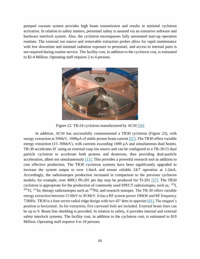
65
pumped vacuum system provides high beam transmission and results in minimal cyclotron
activation. In relation to safety matters, personnel safety is assured via an extensive software and
hardware interlock system. Also, the cyclotron encompasses fully automated start-up operation
routines. The external ion source and removable extraction probes allow for rapid maintenance
with low downtime and minimal radiation exposure to personnel, and access to internal parts is
not required during routine service. The facility cost, in addition to the cyclotron cost, is estimated
to $2-4 Million. Operating staff requires 2 to 4 persons.
Figure 22. TR-24 cyclotron manufactured by ACSI [56]
In addition, ACSI has successfully commissioned a TR30 cyclotron (Figure 23), with
energy extraction at 30MeV, 1600μA of stable proton beam current [57]. The TR30 offers variable
energy extraction (15–30MeV), with currents exceeding 1600 μA and simultaneous dual beams.
TR-30 accelerates H− using an external cusp ion source and can be configured to a TR-30/15 dual
particle cyclotron to accelerate both protons and deuterons, thus providing dual-particle
acceleration, albeit not simultaneously [11]. This provides a powerful research tool in addition to
cost effective production. The TR30 cyclotron systems have been significantly upgraded to
increase the system output to over 1.6mA and ensure reliable 24/7 operation at 1.2mA.
Accordingly, the radioisotopes production increased in comparison to the previous cyclotron
models; for example, over 400Ci Pb-201 per day may be produced for Tl-201 [57]. The TR30
cyclotron is appropriate for the production of commonly used SPECT radioisotopes, such as, 123I, 201Tl, 111In; therapy radioisotopes such as 103Pd; and research isotopes. The TR-30 offers variable
energy extraction between 15 MeV to 30 MeV. It has a RF system power 100kW and RF frequency
73MHz. TR30 is a four-sector radial ridge design with two 45o dees in opposite [61]. The magnet’s
position is horizontal. As for extraction, five carrousel foils are included. External beam lines can
be up to 9. Beam line shielding is provided. In relation to safety, it provides internal and external
safety interlock systems. The facility cost, in addition to the cyclotron cost, is estimated to $10
Million. Operating staff requires 4 to 10 persons.

66
Figure 23. TR-30 cyclotron manufactured by ACSI [56]
Finally, ACSI has successfully commissioned TR-FLEX cyclotron (Figure 24), with a
range of energies from 18 up to 30MeV, depending on configuration. In addition to the adjustable
energy range, the high beam current capabilities allow for full scale commercial production of
SPECT isotopes: 99mTc, 201Tl, 111In,123I, 67Ga, etc, in addition to the PET isotopes. The TR-FLEX
beam profile and output is optimized to provide optimal conditions for both PET and SPECT
radioisotope production. The maximum extracted beam current is 750μAmp. Accelerated ions can
be negative hydrogen ions (H-) and extracted ions H+ using a multicusp ion source. The magnet’s
position is horizontal. The RF frequency is 85MHz. The operating pressure for the vacuum systems
is approximately ~5x10⁻⁷ Torr. The extraction method uses carbon foils with two extraction ports.
Two extraction probes are available; a standard extraction probe with a single carbon foil per side,
and a carousel type - 4 foils per carousel, that is optional. Also, two external beam ports are the
standard configuration. Each beam port allows installation of a beamline or a target selector
depending on the end user’s requirements. Target can be solid, gas or liquid. Different beamline
configurations are available for the TR-FLEX. Up to 6 beamlines can be mounted on the TR-FLEX
cyclotron. The TR-FLEX cyclotron features a smaller footprint compared to typical 30 MeV
cyclotrons, which allows for lower facility costs.
Figure 24. The TR-FLEX cyclotron compared to TR-30 [56]
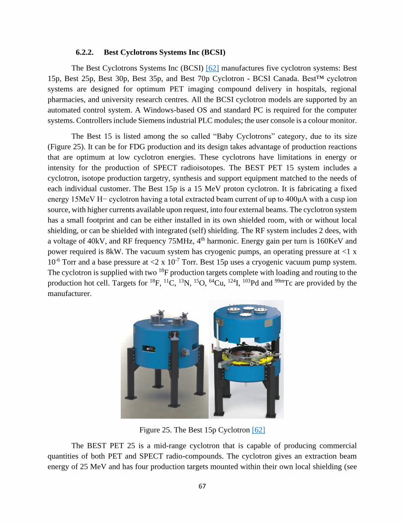
67
6.2.2. Best Cyclotrons Systems Inc (BCSI)
The Best Cyclotrons Systems Inc (BCSI) [62] manufactures five cyclotron systems: Best
15p, Best 25p, Best 30p, Best 35p, and Best 70p Cyclotron - BCSI Canada. Best™ cyclotron
systems are designed for optimum PET imaging compound delivery in hospitals, regional
pharmacies, and university research centres. All the BCSI cyclotron models are supported by an
automated control system. A Windows-based OS and standard PC is required for the computer
systems. Controllers include Siemens industrial PLC modules; the user console is a colour monitor.
The Best 15 is listed among the so called “Baby Cyclotrons” category, due to its size
(Figure 25). It can be for FDG production and its design takes advantage of production reactions
that are optimum at low cyclotron energies. These cyclotrons have limitations in energy or
intensity for the production of SPECT radioisotopes. The BEST PET 15 system includes a
cyclotron, isotope production targetry, synthesis and support equipment matched to the needs of
each individual customer. The Best 15p is a 15 MeV proton cyclotron. It is fabricating a fixed
energy 15MeV H− cyclotron having a total extracted beam current of up to 400μA with a cusp ion
source, with higher currents available upon request, into four external beams. The cyclotron system
has a small footprint and can be either installed in its own shielded room, with or without local
shielding, or can be shielded with integrated (self) shielding. The RF system includes 2 dees, with
a voltage of 40kV, and RF frequency 75MHz, 4th harmonic. Energy gain per turn is 160KeV and
power required is 8kW. The vacuum system has cryogenic pumps, an operating pressure at <1 x
10-6 Torr and a base pressure at <2 x 10⁻⁷ Torr. Best 15p uses a cryogenic vacuum pump system.
The cyclotron is supplied with two 18F production targets complete with loading and routing to the
production hot cell. Targets for 18F, 11C, 13N, 15O, 64Cu, 124I, 103Pd and 99mTc are provided by the
manufacturer.
Figure 25. The Best 15p Cyclotron [62]
The BEST PET 25 is a mid-range cyclotron that is capable of producing commercial
quantities of both PET and SPECT radio-compounds. The cyclotron gives an extraction beam
energy of 25 MeV and has four production targets mounted within their own local shielding (see

68
Figure 26). This configuration allows 18F production on two independent targets as well as two
additional target stations for SPECT radio-isotope production. The cyclotron and the production
targets are enclosed in a single shielded vault, which is cost effective for regional facilities.
Figure 26. The Best 25p Cyclotron [62]
The Best 25p (Figure 26) is accelerating H− having a total extracted beam current of up to
400μA with a cusp ion source, with higher currents available upon request, into four external
beams. The RF system includes 2 dees, with a voltage of 40kV, and RF frequency 74MHz, 4th
harmonic. Energy gain per turn is 240KeV and power required is 25kW. Best 55p uses a cryogenic
vacuum pump system. The vacuum system has cryogenic pumps, an operating pressure at <1 x 10-
6 Torr and a base pressure at <2 x 10⁻⁷ Torr. A beam line extension can be installed in the shielded
vault for dedicated production stations, and for the production of special radioisotopes. A beamline
to a dedicated shielded area can also be included, by modest changes to the facility. The cyclotron
vault is changed by including a beam line and a separation barrier between the dedicated
production target and the rest of the cyclotron area. The cyclotron is supplied with two 18F
production targets, complete with loading, and routing to the production hot cell. Targets for 18F, 11C, 13N, 15O, 64Cu, 124I, 103Pd and 99mTc are provided by the company [62].
The BEST PET 30 has all the features of the B25p, as mentioned above, but may be
upgraded to a B35p when the user requires additional capability. The key upgrade feature is that
the maximum energy of the B30p as delivered is 30 MeV, which provides about twice the amount
of radioisotope that the B25p delivers. This cyclotron model accelerates H- using an external ion
source, multi-cusp 5 mA. Simultaneous dual beam extraction is possible (multiple foil extraction
cartridge). The beam current is 400μΑ. The cyclotron’s targetry includes 4 beam lines. The RF
system includes 2 dees, dee voltage is 60kV, the RF frequency at 22kW (nominal) and the energy
gain per turn is 240KeV. The vacuum system has cryogenic pumps, an operating pressure at <1 x
10-6 Torr and a base pressure at <2 x 10⁻⁷ Torr. A production facility based on the B30p is designed
to allow modifications for the upgrade to the B35p. Therefore, in addition to the PET isotopes
produced by the Best 15p (18F, 11C, 13N, 15O, 64Cu, 124I, 103Pd and 99mTc), Best 30p can further
produce the following SPECT isotopes: Iodine-123 (Low dose imaging agent, replacing 131I),
Iridium-111 (for Blood cell labelling), Gallium-68 (generator) (for blood-brain barrier integrity,

69
tumour localization), Thallium-201 (for myocardium functional assessment), krypton-181m
(generator) (gas for ventilation imaging or in solution for perfusion imaging).
The Best 35p is a 35 MeV proton cyclotron (Figure 27). It is fabricating a varying energy
15-35 MeV depending on configuration. The cyclotron weights 55 tons. It accelerates H− having
a total extracted beam current of up to 800μA with a multi-cusp ion source, with higher currents
available upon request, into 4-6 external beams. It allows simultaneous dual beam extraction
(multiple foil extraction cartridge). The RF system includes 2 dees, with a voltage of 60kV, and
RF frequency 65MHz, 4th harmonic. Energy gain per turn is 240KeV and power required is 22kW.
The vacuum system has cryogenic pumps, an operating pressure at <2 x 10⁻⁶ Torr and a base
pressure at <1 x 10⁻⁷ Torr. It is designed to produce radioisotopes using the (𝑝, 2𝑛) or the (𝑝, 3𝑛)
reaction. There is a broad range of single photon emitters that are used in nuclear diagnostic
imaging and therapy that are accessible in this energy range. Both solid and gas target systems can
be added to the BCSI 35p system [62].
Figure 27. The Best 35p Cyclotron [62]
Finally, the BCSI 70p is a 70 MeV proton cyclotron (Figure 28). The cyclotron weights
195 tons. The 70MeV model accelerates H− from an external multi-cusp ion source and has
simultaneous variable energy extraction from 35 to 70MeV into two external beam lines. The
combined beam current is 700μA and the higher currents available are 1000μA. Custom design
configuration allows for the addition of up to 6 beam lines (Figure 29). In relation to the RF system,
the resonator is 2 dees (separated resonators), the dee voltage is 60 to 81 kV and the RF frequency
is 56MHz, 4th harmonic [63]. The power required for the RF system is 20kW and the energy gain
per turn is 240 to 300keV. The vacuum system has cryogenic pumps, an operating pressure at <2
x 10-6 Torr and a base pressure at <1 x 10⁻⁷ Torr. Cryogenic pump system is used for the vacuum
system. The energy provides access to radionuclides produced by (𝑝, 𝑥𝑛) reactions and is a
research accelerator as well as a radioisotope production cyclotron. Both solid and gas target
systems can be added to the BCSI 70p system. The BCSI 70p cyclotron is appropriate for

70
radioisotope production and research applications [57]. The simultaneous beam extraction on
opposite lines allows for the use of the cyclotron for research purposes.
Figure 28. The Best 70p Cyclotron [62]
Figure 29. Beam line layout of a Best 70p cyclotron [57]
6.2.3. IBA
IBA is one of the world leaders in particle accelerator technology [64]. IBA markets PET
and SPECT cyclotrons ranging from 3.8 to 30 MeV in beam energy, specifically, at 3 (D-), 10/5
(H-/D-), 11 (H-), 18/9 (H-/D-), 30 (H-) and 70/35 (H-/D-) MeV [65; 66; 67]. The Cyclone 3D (Figure
30) was originally marketed to address the need for 15O in the early 1990s. The original four-pole
geometry has been replaced by three poles to provide additional vertical focussing. It generates a
50 μA beam of 3.6 MeV deuterons which strike a nitrogen gas target to produce oxygen 15 via the 14N(d,n)15O reaction [68]. The cyclone 3 was originally conceived as a classical cyclotron with
plane pole faces, which were later modified to incorporate sector focussing. The plane of
acceleration is vertical with the target at the bottom. The weight of the cyclotron is approximately
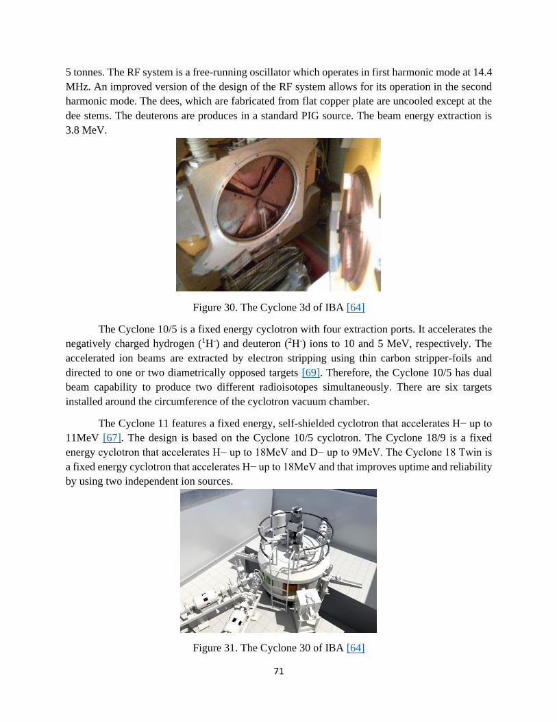
71
5 tonnes. The RF system is a free-running oscillator which operates in first harmonic mode at 14.4
MHz. An improved version of the design of the RF system allows for its operation in the second
harmonic mode. The dees, which are fabricated from flat copper plate are uncooled except at the
dee stems. The deuterons are produces in a standard PIG source. The beam energy extraction is
3.8 MeV.
Figure 30. The Cyclone 3d of IBA [64]
The Cyclone 10/5 is a fixed energy cyclotron with four extraction ports. It accelerates the
negatively charged hydrogen (1H-) and deuteron (2H-) ions to 10 and 5 MeV, respectively. The
accelerated ion beams are extracted by electron stripping using thin carbon stripper-foils and
directed to one or two diametrically opposed targets [69]. Therefore, the Cyclone 10/5 has dual
beam capability to produce two different radioisotopes simultaneously. There are six targets
installed around the circumference of the cyclotron vacuum chamber.
The Cyclone 11 features a fixed energy, self-shielded cyclotron that accelerates H− up to
11MeV [67]. The design is based on the Cyclone 10/5 cyclotron. The Cyclone 18/9 is a fixed
energy cyclotron that accelerates H− up to 18MeV and D− up to 9MeV. The Cyclone 18 Twin is
a fixed energy cyclotron that accelerates H− up to 18MeV and that improves uptime and reliability
by using two independent ion sources.
Figure 31. The Cyclone 30 of IBA [64]

72
The Cyclone 30 (Figure 31) is a cyclotron that accelerates H− up to 30MeV and can extract
two independent beams (dual proton beam). Beam current can be set to 400µA, 750μA and
1500μA and upgradable throughout product lifetime. Beam energy ranges from 15 to 30 MeV
gives the flexibility to produce a wide range of radioisotopes, including 18F, 64Cu, 89Zr but also
copious quantities of 68Ge, 123I, 111In, 201Tl and 225Ac. The Cyclone 30 XP is another product line;
it accelerates proton and alpha beams up to 30MeV and deuterons up to 15MeV. Protons and
deuterons are accelerated as negative ions and extracted by stripping and at variable energy. The
alpha beam is accelerated as He++ and extracted with an electrostatic deflector [65].
The Cyclone 30XP combines routine isotope production with the new generation of
medical radioisotopes used in the field of diagnosis and therapy as well as research works. The 30
MeV alpha beam is well suited to produce isotopes as 211At, a promising alpha emitter for
radiotherapeutic use. While proton and deuteron are accelerated in the negative ion mode and
extracted with stripping system, the positive alpha beam (He++) is accelerated and extracted in
positive ion mode using an electrostatic deflector.
The Cyclone 70P (proton only) is a multiparticle, accelerates H− up to 70MeV as well
accelerating alpha beams (Figure 32). Energy range from 30 to 70 MeV, which provides the
flexibility to produce a wide range of radioisotopes, including 68Ge, 82Sr for PET use, but also
other nuclear medicine isotopes, such as 123I, 111In, 201Tl.
The specifications for the Cyclone 70 installed in Arronax had the H− at variable energy
from 35 to 70MeV, with a maximum current of 750μA, D− from 17 to 25MeV at 50 μA, He++ at
70MeV and 35 μA, and H+2 at a fixed 35MeV and a maximum current of 50 μA. The Cyclone
70XP produces proton, deuteron, and alpha beams, with energy levels of up to 70 MeV. While
protons and deuterons are accelerated in the negative ion mode and extracted with two stripping
systems, the positive alpha beam (He++) is accelerated and extracted in positive ion mode using
an electrostatic deflector. The Cyclone 70 XP can be used to produce medical radioisotopes used
in the field of diagnosis and therapy, as well as research work.
Figure 32. The Cyclone 70 of IBA [64]

73
IBA also manufactures a compact superconducting synchrocyclotron (S2C2) for proton
therapy treatment system called ProteusOne [70]. The S2C2 (Figure 33) is the first
synchrocyclotron as well as the first superconducting accelerator ever produced at IBA. It is a non-
isochronous machine, with different beam physics. It uses a PIG Cold Cathode ion source. The
maximum beam energy is 230 MeV and the extracted beam current is approximately 200 nA. Yoke
radius is 1.25 m, pole radius 50 cm and its weight 50 tons. The cyclotron’s weight is 60 tons. The
magnet has a rotationally symmetric pole and a superconducting coil to provide the maximum
magnetic field of 5.7 T, whereas the extraction magnetic field is 5T [71]. The cooling system is
conductive (4x1.5 W cryocoolers). The S2C2 has a 1-dee system, with a varying RF frequency
from 92 to 62 MHz, voltage at 10 kV and power a few kWatt [70].
Figure 33. S2C2 layout [72]
6.2.4. KIRAMS
The Cyclotron Application Laboratory KIRAMS [73] has developed two cyclotrons for
PET radioisotope production. The KIRAMS-13 (Figure 34) accelerates H− from an internal PIG
ion source up to 13MeV and extracts currents of up to 50mA through two ports. The design OF
Kirams-13 calls for a four–Sector radial ridge geometry with the magnetic field ranging between
1.99T in the hill and 0.84T in the valley respectively, resulting in an average field of 1.3T. There
are 43.5o of dees and fixed operating frequency for RF system is 77.3MHz. Maximum dee voltage
is 40kV. The acceleration chamber is evacuated, primarily, with the help of two diffusion pumps.
The ion source is an internal cold cathode PIG. The extraction method includes stripping, using a
thin foil to intercept the beam with automatically three-fork change carbon foil system [74]. Even
though the Kirams-13 model has been developed in 2001, ever since improvements have been
applied in the design of the model. For instance, the magnet design was changed to reduce electric
power consumption (about 67%). Main RF parameters, such as resonant frequency, RF power, dee
structure, cavity structure, etc., were not changed to reduce production cost and time [75].
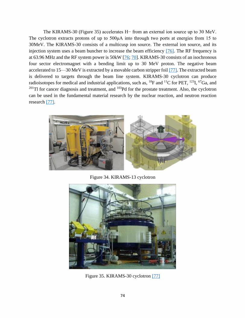
74
The KIRAMS-30 (Figure 35) accelerates H− from an external ion source up to 30 MeV.
The cyclotron extracts protons of up to 500μA into through two ports at energies from 15 to
30MeV. The KIRAMS-30 consists of a multicusp ion source. The external ion source, and its
injection system uses a beam buncher to increase the beam efficiency [76]. The RF frequency is
at 63.96 MHz and the RF system power is 50kW [76; 70]. KIRAMS-30 consists of an isochronous
four sector electromagnet with a bending limit up to 30 MeV proton. The negative beam
accelerated to 15—30 MeV is extracted by a movable carbon stripper foil [77]. The extracted beam
is delivered to targets through the beam line system. KIRAMS-30 cyclotron can produce
radioisotopes for medical and industrial applications, such as, 18F and 11C for PET, 123I, 67Ga, and 201Tl for cancer diagnosis and treatment, and 103Pd for the prostate treatment. Also, the cyclotron
can be used in the fundamental material research by the nuclear reaction, and neutron reaction
research [77].
Figure 34. KIRAMS-13 cyclotron
Figure 35. KIRAMS-30 cyclotron [77]

75
6.2.5. GE Healthcare
GE Healthcare [78] has two cyclotron products for PET, namely MINItrace and PETtrace.
MINItrace accelerates H− in a vertically oriented cyclotron that provides 50 μA at a fixed energy
of 9.6MeV. The MINItrace is appropriate for the production of 18F via the O18 (p, n) F18 reaction
[79]. The MINItrace cyclotron features integrated shielding and fully automated operation during
start-up, tuning and operation [11]. Although the MINItrace cyclotron is designed to be a self-
shielded system, it is still possible to monitor the neutron release from the target in real time outside
the cyclotron by using a high-sensitivity moderated 3He neutron detector [79].
The PETtrace cyclotron is specifically designed for the production of radioactive PET
tracers [80] such as daily productions of 18F and monthly productions of 64Cu and 89Zr [81]. In
addition to radioisotope production for medical purposes, the PETtrace cyclotron can be also
utilized to produce research radioisotopes, such as 11C and 13N [80], but also it can be used for
Boron neutron capture therapy (BNCT) [82]. PETtrace accelerates in a vertical plane either H−/D−
up to a fixed energy of 16.5/8.6MeV, with extracted currents of 100/65μA [11]. During solid target
irradiations, beam currents up to 40 µA are used [81]. The GE PETtrace is popular among nuclear
pharmacies and clinics in many countries because it is compact and reliable [82]. Targets are
accessible and easily changeable. The cyclotron can use dual targets simultaneously, allowing the
flexibility to work on radioisotope production and BNCT with minimal investments of time and
work force [82]. Asp et al., [81] in their recent work tried to develop a dedicated beam port on the
existing PETtrace cyclotron to enable radiobiological studies using proton beams.
6.2.6. VARIAN
VARIAN [83] manufactures superconducting compact proton cyclotrons for proton beam
therapy. The concept of this machine was proposed by Henry Blosser and his team in 1993 at
Michigan State University [84]. The concept was further developed, and the machine was
manufactured by ACCEL Instruments GmbH. The first beam was extracted from the machine in
2005. In 2007, Varian Medical Systems, Inc. bought ACCEL and in early 2009, the company was
re-structured forming the Varian Medical Systems Particle Therapy GmbH (VMS-PT) [85].
The 250 MeV machine serves as proton source for cancer proton therapy. The VARIAN’s
superconducting compact cyclotron is an azimuthally varying field isochronous machine which
delivers a 250 MeV beam and the extracted current (max) is 800nA. The iron yoke has an outer
diameter of 3.1m, height 1.6m and weight less than 90 tons. The accelerator has a four-sector
magnetic structure with four accelerating dees installed in the valleys (Figure 36) [71]. The SC
magnet yields a central field of 2.4T, stored energy is at 2.5MJ, and maximum filed at the coil is
approx. 4T. The operating current for the magnet is 160A and the rated powers of cryocoolers is
40kW. The RF system has a frequency at 72.8 MHz, and the RF power is less than 115kW. The
peak dee voltage at the centre and in the extraction region is 80 and 130 kV, respectively [71]. The
cyclotron uses a zero boil-off liquid helium cryosystem [85].

76
VARIAN currently commercializes the ProBeam 360o solution (Figure 37), which includes
the superconducting cyclotron, a beam transport system (i.e., focuses, shapes, and guides the beam
to the treatment room, creating the small beam size necessary for IMPT), and a 360-degree rotating
gantry allowing imaging and treatment of the patient from any angle without additional
repositioning [86].
Figure 36. Varian cyclotron: 1—sector shim, 2—dee, 3—magnet yoke [71]
Figure 37. ProBeam VARIAN Platform [86]

77
Table 6. Comparison of commercial cyclotrons for medical applications
ACSI IBA
Cyclotron
model
TR-19
ACSI
TR-
FLEX
ACSI
TR-24
ACSI
TR-30
ACSI
Cyclo
ne 3
Cycl
one
10/5
Cycl
one
11
Cycl
one
18/9
Cycl
one
30
Cyclo
ne
30XP
Cycl
one
70
Proto
n
Cyclo
ne
70XP
S2C2 G
ener
al I
nfo
rmat
ion
Cyclotron
weight, t 22 - 84 56 5 12 13 - 50 50 140 145 60
PET/ SPECT
isotopes PET
PET,
SPEC
T
PET,
SPEC
T
SPEC
T PET PET PET PET
PET,
SPE
CT
PET,
SPEC
T
PET,
SPE
CT
PET,
SPEC
T
No
Research
isotopes Yes Yes Yes Yes No Yes Yes Yes Yes Yes Yes Yes No
Therapeutic
isotopes No Yes Yes Yes No No No No Yes Yes Yes Yes
Proto
n
therap
y
Ion
Type of ions H- /D- H- /
H+ H- H- /D- D+
H-
/D- H+
H-
/D-
H-
/D-
H-
/D-/
4He+
+
H-
H-
/D-
/H2+/
He++
H-
Ion source
type cusp cusp
multic
usp
multic
usp PIG PIG PIG PIG
multi
-cusp
multi
-cusp
multi
-cusp
multi-
cusp
and
ECR4
PIG
Bea
m Extracted
beam current,
μA
>300 750 >500 5 >1000 60 >100
(35) 120
150
(40) 1500
400/5
0/506 750
750/5
0/507
~ 200
nA
4 multi-cusp (P+, D-) + ECR (HH+, He++) 5 *External ion source allows the current output to be upgraded to a maximum current of 1mA 6 400 (H-) 50 (D-) 50 (4He++) 7 750 (H-) 50 (D-) 50(4He++)

78
Energy
extraction,
MeV
14-19 18-30 18-24 15-30 3.8 10
(5) 11
18
(9)
30
(15)
400
/8-15/
308
30/
70
30 -
70 230
Mag
net
Magnet
position9 V H H /V H V H H H H H H H H
RF
Syst
ems
Resonator 10 2 2 2 - 2 2 2 2 2 2 2 2 2
Dee voltage,
kV 50 - 50 50 - - - 32 - - 50 - 10
RF frequency,
MHz
73.2
(36.6) 85 85.085 73 14.4 42 42 42 65 33-66 62
30-
6011
92 -
62
RF system
power, kW 20 60 - 100 - - - 10 100 40 100 100
few
kWatt
Note: a dash is being added whenever the information has not been retrieved.
8 400 (H-) 8-15 (D-) 30 (4He++) 9 Or plane of acceleration (Vertical / Horizontal) 10 number of dees 11 Depending particles mass
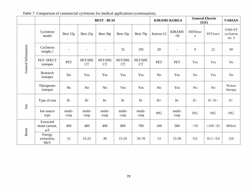
79
Table 7. Comparison of commercial cyclotrons for medical applications (continuation).
BEST - BCSI KIRAMS KOREA General Electric
(GE) VARIAN
Gen
eral
Info
rmat
ion
Cyclotron
model Best 15p Best 25p Best 30p Best 35p Best 70p Kotron-13
KIRAMS
-30
MINItrac
e PETtrace
VMS-PT
cyclotron
no. 3
Cyclotron
weight, t - - - 55 195 20 - 9 22 90
PET/ SPECT
isotopes PET
PET/SPE
CT
PET/SPE
CT
PET/SPE
CT
PET/SPE
CT PET PET Yes Yes No
Research
isotopes No Yes Yes Yes Yes No Yes No Yes No
Therapeutic
isotopes No No No Yes Yes No Yes No No
Proton
therapy
Ion
Type of ions H- H- H- H- H- H+ H- H− H−/D− H−
Ion source
type
multi-
cusp
multi-
cusp
multi-
cusp
multi-
cusp
multi-
cusp PIG
multi-
cusp PIG PIG PIG
Bea
m
Extracted
beam current,
μA
400 400 400 800 700 100 500 >50 >100 / 65 800nA
Energy
extraction,
MeV
15 15-25 30 15-35 35-70 13 15-30 9.6 16.5 / 8.6 250

80
Mag
net
Magnet
position12 H H H H H H H V V H
RF
Syst
ems
Resonator 13 2 2 2 2 2 2 2 2 2 4
Dee voltage,
kV 40 60 60 60 60-81 45 - - - 80 / 130
RF frequency,
MHz 75 74 65 65 56 77.3 63.96 101 27.2 72.8
RF system
power, kW 8 25 22 22 20 30 50 - - ≤115
Note: a dash is being added whenever the information has not been retrieved.
12 Or plane of acceleration (Vertical / Horizontal) 13 number of dees

81
6.3. Accelerator-Produced Isotopes
6.3.1. Radioisotopes for scientific research
Accelerators in rare isotope research facilities produce isotopes either by the ISOL (isotope
separation on-line) technique or by projectile fragmentation. The isotopes of interest to nuclear
physicists at these facilities are too short-lived to collect for off-site applications and must be
quickly delivered to experimental stations. The primary use of these rare isotope beams is to study
nuclear structure, nuclear astrophysics, and fundamental symmetries. Research cyclotrons at
TRIUMF [87], RIKEN [88; 89] and other particle accelerator centres are being used to produce
rare isotopes for fundamental research science and other applications. For the cyclotron models
presented above, it is claimed by the cyclotron vendors that certain models are appropriate for the
production of research isotopes (e.g., TR-FLEX, and TR-30) in addition to PET and/or SPECT
radioisotopes.
6.3.2. Radioisotopes for pharmaceutical and medical applications
Even though the development of the first cyclotron dates in the 1930s, their use for the
production of radioisotopes for medical applications revived after the second World War in the
1950s, after the discovery that 201Tl could be used as an ideal tracer for detecting myocardial
perfusion [90]. The preparation of fluorodeoxyglucose (18FDG) in the mid-1970s and its use for
studying glucose metabolism was a breakthrough, leading to the development of the widely used
PET imaging technique. The use of 18FDG along with a PET camera yields good quality images
of the brain (for studying functional abnormalities), heart (for studying viability function) and
tumours (especially for metastases’ detection). Many other 18F and 11C labelled
radiopharmaceuticals were developed subsequently, and the quest for newer and more effective
ones continues at present. The radioisotopes used for medical applications have half-lives that are
long enough for them to be isolated, chemically attached to appropriate molecules and observed
in situ for a length of time commensurate with the process of interest. They are primarily used as
tracers and as a diagnostic tool in PET-CT or SPECT scans and can be also used for radiotherapy.
Most of the cyclotron models examined above can be used for medical applications. In tables 6
and 7, it is specified for each model whether the isotopes produced are appropriate for PET and/or
SPECT scanning, research, and therapeutic purposes.
An indicative list of such radioisotopes which have medical applications is given below
[44; 91]: Arsenic-73 (80.3 d) is used for labelling and PET imaging, Carbon-11(20m) is used in
PET for imaging of tumours and therapy, Copper-64 (13 h) is used to study copper metabolism,
for PET imaging of tumours and therapy, Flourine-18 (110m) is used in FDG for detecting cancers
and monitoring the progress of treatment, Gallium-67 (78 h) is used for lung tumour imaging and
localization of lesions, Gallium-68 (68m) is a used in PET and PET/CT for biomedical imaging,
Indium-111 (2.8 d) is used as a diagnostic in brain and colon studies, Iodine-123 (13 h) is used for
diagnosis of thyroid function, Iodine-124 (4.2 d) is used as a tracer, Krypton-81m (13 s) is used to

82
study the function of pulmonary ventilation and for the early diagnosis of lung diseases, and is
produced as a daughter of rubidium-81 (4.6 h), Nitrogen-13 (10m) is used with PET as a blood
flow tracer, Oxygen-15 (2m) is used to label gases for inhalation to measure blood flow and oxygen
consumption, Rubidium-82 (1.3m) is used in PET for myocardial perfusion imaging, Sodium-22
(2.6 y) is used as a positron source in calibrating ion chambers and PET cameras, Technetium-
94m (53m) can be used as a substitute for technetium-99m, Technetium-99m (6 h) is used for
imaging the brain, liver, bone marrow, kidney and heart, Thallium-201 (73 h) is used for diagnosis
of coronary artery disease, Yttrium-86 (14.7 h) is used as a tracer in bone pain palliation,
Ziconium-89 (3.3 d) is used with PET for labelling proteins.
In addition, and since there is an increasing expectation for more use of the radioisotopes
for medical therapy, therapeutic radiopharmaceuticals make use of radioactive isotopes that can
be localized near weakened malfunctioning cells to destroy them with the decay radiation. Hence,
apart from the PET and SPECT isotopes for diagnostic imaging purposes, cyclotrons can also
produce isotopes for therapeutic applications. Large beam currents are required to this end. One of
such isotopes produced is the 103Pd for brachytherapy applications. Another example is the
production of alpha particle emitting isotopes, notably 211At and 213Bi, for targeted therapy of
cancer. A more extensive list of such radioisotopes is given below: Actinium-225 (10 d) and its
daughter bismuth-213 are used for cancer therapy, Astatine-211 (7.2 h) is an alpha emitter that is
used for therapy, Bismuth-213 (46m) is used in alpha immunotherapy, Copper-67 (2.6 d) is used
in therapy, Palladium-103 (17 d) is used in brachytherapy seeds in the treatment of rapidly
proliferating tumours.
In 2005, an IAEA report estimated that, worldwide, there were about 350 cyclotrons that
were primarily used for the production of radionuclides [92]. Nearly 50% of these were in the 10-
20 MeV energy range and about 75% of the cyclotrons were being used to produce 18F for FDG.
In Table 8, lists commonly used radioisotopes produced by cyclotrons, some of the possible
nuclear reactions used to produce the isotopes, typical production yields and some key physical
properties for the target and production isotopes.
Table 8. List of medical isotopes produced by cyclotrons
Medical
Isotope
Lifetime
T1/2 Use
Nuclear
Reaction
Target
Abundance
(%)
Energy
Range
(MeV)
Production
Yield
(mCi)
Typical
Dose
(mCi)
11C 20.4m PET 11B(p,n) 80.3 8 – 20 40/μA
11C 20.4m PET 14N(p,α) 99.6 12 100/μA
11C 20.4m PET 10B(d,n) 19.7 7 100/μA
13N 9.96m PET 13C(p,n) 1.1 5 – 10 115/μA
13N 9.96m PET 16O(p,α) 98.9 2 – 6 50/μA
13N 9.96m PET 15N(p,n) 99.8 8 – 18 65/μA
15O 2m PET 16O(p,pn) 0.36 10 – 15 47/μA
15O 2m PET 14N(d,n) 99.8 >26 25/μA
15O 2m PET 18O(p,n) 99.6 8 – 6 27/μA
18F 109.8m PET 20Ne(d,α) 0.20 8 – 17 180/μA 5 – 20

83
18F 109.8m PET 64Ni(p,n) 90.5 82/μA
64Cu 12.7h SPECT 68Zn(p,2p) 0.93 5 – 20 5/μA
67Cu 61.9h SPECT 68Zn(p,2n) 19.0 >40 0.02/μA
67Ga 78.3h SPECT
85Rb(p,4n)
82Sr
Produces
Rb
19.0 20 – 40 4.5/μA 10
82Sr /
82mRb
25d /
5m PET
100Mo(p,2
n) 72.2 50 – 70 0.18 /μAh
99mTc 6h SPECT 103Rh(p,n) 9.7 19 14/μAh 20
103Pd 17.5d Therapy 103Rh(p,n) 100 10 – 15 0.52/μAh
111In 67.2h SPECT 112Cd(p,2n
) 24.1 18 – 30 6/μAh 3
123I 13.2h SPECT
124Xe(p,2n
)123Cs
→123Xe→
123I
0.10 25 – 35 27/μAh
123I 13.2h SPECT 123Te(d,2n
) 123I 0.89 10 – 15 20/μAh
124I 4.1d PET 124Te(p,n) 4.7 10 – 18 0.1/μAh
124I 4.1d PET 124Te(d,2n
) 4.7 >20 0.15/μAh
186Re 90.6h Therapy/
SPECT 186W(p,n) 28.4 18
201Tl 73.5h SPECT
203Tl(p,3n)
201Pb
→201Tl
29.5 27 – 35 0.7/μAh 4
211At 7.2h Therapy 209Bi(α,n) 100 28 1/μAh 0.05 –
0.1

84
Chapter 7
7. Discussion and Conclusions
7.1. Cyclotron in the market for medical isotopes production
Cyclotrons are the primary tool for producing the shorter-lived, proton-rich radioisotopes
currently used in a variety of medical applications. Although the primary use of the cyclotron-
produced short-lived radioisotopes is in PET-CT and SPECT diagnostic medical procedures,
cyclotrons are also producing longer-lived isotopes for therapeutic procedures as well as for other
industrial and applied science applications. In addition, superconducting compact cyclotron
models, with extracted beam energy up to 250 MeV, are used for proton therapy. This inquiry
yielded 23 different cyclotron models, manufactured by six cyclotron vendors. Commercial
suppliers of cyclotrons are responding by providing a range of cyclotrons in the energy range of
3–70MeV for the differing needs of the various applications. These cyclotrons generally have
multiple beams servicing multiple targets. In addition, operational superconducting cyclotrons,
manufactured by Varian and IBA are widely and successfully used for proton therapy. The findings
of this thesis provide a comparison of some of the technical requirements and capabilities of the
various current cyclotrons that are available in the market.
7.2. Cyclotron technical specifications and design requirements
For PET/SPECT imaging, what is of high interest to the end user in the medical sector, is
the primary cyclotron specification provided by the target yield for a given radioisotope in the
form of a particular molecule within a specified irradiation time. For the cyclotron designer, this
user-provided specification leads to decisions on the ideal nuclear reaction (projectile) to be used,
the target material, the target chemistry, the projectile energy, and the projectile current (flux) on
target. The accelerated particles must have adequate energy for the chosen nuclear reaction and
adequate current to provide the required yields at that energy. Higher energies (at the same current)

85
generally result in a greater product yield, but often lead to increased impurities. Hence, there is a
trade-off between purity, energy and current. Each product has its own ideal energy and current.
Therefore, the most appropriate cyclotron model from those presented in this thesis, can be
determined based on the aims of the end user. Cyclotrons that provide beams of variable energy,
such as, TR30 and Best 70p, can optimize for different radioisotopes, albeit with greater
complexity and added cost. Secondary specifications include, the number of targets, the target
dimensions, the number of extracted beams (ports), shielding (facility) requirements, activation,
and operating costs. Regularly, compromises are needed to arrive at a manageable facility budget.
For the cyclotron models presented in this thesis, some specifications appear to have
commonalities. Most of the cyclotrons accelerate the negative H− and/or D− ions because of the
ease of extracting multiple beams, each with variable current, into targets that are usually
separately shielded by steel or concrete. In relation to shielding options, most manufacturers have
the option of self-shielding for the cyclotrons when the maximum energy is less than 15MeV. For
the lower energy cyclotrons, the customer must choose between vault (concrete) shielding and the
generally more expensive but compact arrangement of close-packed steel around the cyclotron and
targets. The choice of either internal or external targets impacts the footprint of the system and the
radiation exposure for personnel servicing the cyclotron. In addition, for ion currents less than 200
μA, an internal PIG (Penning ionization gauge) ion source [93] is the preferred cost-effective
choice (e.g., Cyclone 3, 10/5, 11 and 18/9 of IBA). If H− currents greater than about 200μA are
required, then an external (Cusp) ion source is required. With internal targets and H+ acceleration,
high currents are readily achievable with internal PIG type ion sources. Extraction of intense H+
beams regularly leads to severe component activation in the cyclotron. Also, the most common
choice for the magnet appears to be a conventional room temperature coil. In all cases, if the
cyclotron’s design allows the generation of two or more simultaneous beams of varying energies
and intensities, then the cyclotron can be used for multiple purposes, including to produce research
isotopes.
For proton therapy application, the extracted beam energy of compact cyclotrons is
reaching the 250 MeV/nucleon. The possibility of the extracted beam energy variation due to fact
that the magnetic field scales linearly with operating current in such accelerators (SC
synchrocyclotron is an example) is a valuable advantage of this class of the machines. Variable-
energy synchrocyclotrons are theoretically feasible; yet this remains a prototype challenge for
engineers [71].
In addition, through the review of the several cyclotrons, it has become obvious that certain
requirements should be safeguarded to satisfy the end-user and the cyclotron designer. Those
requirements can be classified in terms of importance for the end-users and challenge level for
cyclotron designers. A very important requirement for both the end users and the cyclotron
designers is the low radiation doses for the personnel. The cyclotron design must ensure very low
beam losses, which can be attained when: cyclotron parts are easy to mount and dismount, parts
are made from materials that are difficult to activate and from material with the minimum quantity

86
of impurities having a large cross-section to possible nuclear reactions. For end-users what is of
outmost importance is ensuring reliability, low cost, and simplicity (i.e., can be used by low-skilled
persons without too much technical background). The requirements of simplicity can also be
extended by a remote or unattended automatic operation of the cyclotron.
The occupied space and weight comprise other important factors for the end users and
challenges for cyclotron designers. Practically end-users are interested by cyclotrons that have a
minimum possible footprint and enter a vault that has height only slightly higher than that of the
cyclotron. This diminishes the cost of bunker or building where the cyclotron is installed. On the
other hand, cyclotron designers always consider it a challenge to design a cyclotron that is smaller
than other machines. This is also interesting due to the recent increase of prices of iron used for
the cyclotron magnet production [55].
Beam quantity and beam quality are other important factors. Radioisotope producers are
mainly interested by the quantity of produced radioisotopes but the beam quality (i.e., the beam
emittance) is frequently irrelevant for them. On the other hand, an end-user is interested in having
the beam entering the target without destroying the target window due to too small beam emittance
(hot spot) or without any losses on collimators due to too large emittance. Cyclotron designers are
interested in obtaining the smallest small beam emittance possible because it guarantees the
smallest beam losses during beam acceleration and beam extraction from the cyclotron.
A less important requirement for the end user but still a challenge for a cyclotron designer
is the consumed electric power. The cyclotron designers always try to minimize the electric power
necessary for the magnet and all cyclotron subsystems. It is also quite frequent that the electric
power distributed in cyclotron magnet coils is much smaller than the sum of electric power of other
elements. Cyclotron end-users producing the radioisotopes are less interested in this requirement
and they have a possibility to reflect the price of electricity in the final price of distributed
radioisotopes.
Finally, a not very important requirement for the end user but still frustrating feature for
the cyclotron designers is the adaptability of the cyclotron. The end-users do not require cyclotrons
able to accelerate many types of ions to the different kinetic energies. Two types of accelerated
ions (different charge state/mass ratio) are frequently demanded, e.g., the protons and the D ions
with the fixed kinetic energy at extraction. Cyclotron designers however envision a design of
versatile cyclotrons accelerating any type of ions.
In addition to the technical specifications of the cyclotron per se, laboratories and facilities
installing a cyclotron for radioisotope production must be equipped with a range of production and
analytical instrumentation [94]. For the production facility, the major equipment required is the
cyclotron and the so-called hot cells/ hot labs. For a facility that includes an imaging centre (e.g.,
a PET-CT), the scanner is an additional equipment. All in all, the type of equipment and the
quantity depend largely upon the scope of the facility: cyclotron (9-30MeV), hot cells, radiation
protection (shielding, monitoring), synthesis modules etc.

87
7.3. Radioisotopes for PET/SPECT imaging, radiotherapy, and
radiotracers
The use of radionuclides for medical applications can be broken down into three general
categories: imaging (PET/ SPECT), radiotherapy and radiotracers. The term radiotracer refers to
a radioactive species that is used to follow (trace) the uptake into, or function of, an organ system
in a living plant or animal or of a physical and chemical process. Initially, the radioactive isotopes
of naturally occurring elements or chemical congeners of these elements were used as radiotracers.
The use of radioiodine to monitor iodine uptake in the thyroid and the use of radioactive
phosphorus to monitor metabolism is an example of a simple radiotracers. The use of
radioisotopes, for imaging (cancer diagnosis) and treatment (radiotherapy) which are produced by
cyclotrons, is grounded on the fact that certain radioisotopes emit gamma rays with sufficient
energy that they can be detected outside of the body. If these radioisotopes are attached to
biologically active molecules, the resulting compounds are called radiopharmaceuticals. They can
either localize in certain body tissues or follow a particular biochemical pathway [92].
The above-mentioned uses rely on the fact that radionuclides are used at tracer
concentrations. In order to be used as tracers, the radionuclides and the compounds to which they
are attached must obey to certain tracer principles: the tracer behaves or interacts with the system
to be probed in a known and reproducible fashion; the tracer does not alter or unsettle the system
in any measurable manner and; the tracer concentration can be measured. In internal radiotherapy
for treating cancer and other diseases, the second principle does not apply in a strict sense since
the purpose of delivering the radiotoxic substance is to have the emitted radiation cause damage
to the tumour tissues. However, for the radiotoxic substance to be localized, it must follow the
known chemical behaviour without perturbing that pathway.
Most of the radiotracers used in vivo should have relatively short half-lives (less than a few
hours to at most a few days). Using short-lived radionuclides comes with pros and cons. One
advantage is the low radiation following the intervention. A disadvantage is linked to the need for
an accelerator nearby or within easy shipping distance for the longer-lived species (a few hours),
and for rapid chemical procedures, especially for formation of more complex compounds.
An extensive list of radionuclides used for PET/ SPECT scanning and therapy is provided
in the Results. However, the most typical radionuclides used in all cases, are summarized in Table
9.
Table 9. Typical radionuclides used for cancer diagnosis and therapy
Radionuclide Half-life Use
Carbon-11 20.3 min PET imaging
Nitrogen-13 10 min PET imaging
Oxygen-15 2 min PET imaging
Fluorine-18 110 min PET imaging
Iodine-123 13 h SPECT imaging
Rhenium-186 90 h radiotoxic nuclide for therapy, and imaging tumors

88
The use of radioisotopes in therapy is based on the fact that a radionuclide that has a high
linear energy transfer (LET) associated with its decay products, such as Auger electrons, beta
particles or alpha particles, to a biologically active molecule that can be directed to a tumour site.
Most of the radionuclides currently used for this purpose are produced in a reactor. However, some
cyclotrons can also produce radionuclides to serve this purpose. For instance, 103Pd, which is used
in treating prostate cancer can be produced by (18 MeV) cyclotrons.
Overall, cyclotrons which produce radionuclides such as those mentioned above, can be
categorized intro three broad (proton) energy ranges based on their primary function and type of
radioisotopes produces14. The first category includes cyclotrons with proton energy less than 20
MeV, which are primarily used for producing PET radionuclides. These PET isotopes tend to have
short half-lives and the cyclotrons are in regional centres/hospitals determined by the yield loss
due to the delivery time from cyclotron to patient. Many of the cyclotrons have the capability of
being shielded with close-packed steel and thereby reduce the need for the user to provide a heavily
shielded bunker. The delivery time of the radioisotope, the patient dose requirement and the
number of doses required per day lead to a cyclotron providing up to 50 μA per target. Many of
the current cyclotrons have the capability of using multiple targets on each of two or more extracted
beams. The second category includes cyclotrons with proton energies between 20 to 35 MeV,
which are primarily used to produce many of the gamma-emitting radioisotopes (commonly used
as imaging radioisotopes for SPECT) as well as the production of several PET isotopes. The
SPECT isotopes have medium half-lives and production generally takes place in dedicated
facilities. The longer half-lives permit isotope delivery to more distant users and this leads to
dedicated production facilities with high power targets and larger throughput. Last, a third category
includes cyclotrons providing protons with energies of greater than 35 MeV, which are used in the
production of a number of the isotopes used for radiotherapy [94]. The primary need is for high
current cyclotrons with currents in the 1mA range.
7.4. Limitations
The operation and functionality of a cyclotron comes with some limitations. A first and
quite self-evident limitation, is the fact that the cyclotron cannot accelerate neutral particles, but
only charged ones. A second limitation is that lighter elementary particles, such as electrons, or
positrons, cannot be accelerated, since such an attempt would require important changes or
modifications of the machine. Third, for a classical cyclotron another limitation is linked to when
the charged particles reach relativistic speed, but this limitation has been already addressed with
the design and construction of cyclotron’s variants, as presented earlier in section 3.7 Different
types of cyclotrons. In brief, the synchrocyclotron is a device that addresses the limitation due to
14 For reasons based on efficiency and cost consideration, some manufacturers have chosen cyclotrons and reactions
that use deuterons and helium as a projectile.

89
relativistic effect. In this case, the frequency of oscillator is reduced gradually in order to maintain
the resonance with the spiral motion of charged particle, but the magnetic field remains constant
as in the case of a cyclotron. The classical cyclotron is also limited by the mere requirement of
magnet size as radius of dees increases with increasing speed of the particle being accelerated (see
equation 40). In synchrotron as against synchrocyclotron, both magnetic field and electric field are
variable. This variation aims to address both the limitations due to relativistic effect as well as due
to the requirement of large cross section of magnets. The particle is accelerated along a fixed large
circular path inside a torus shaped tunnel. The magnetic field here bends the particle, whereas
electric field changes speed. In that way, the requirement of a large cross section of magnet is
converted into multiple bending magnets along a large radius, fixed circular path.
Another limitation, not directly linked to the functionality of the cyclotron but rather the
reactions that take place, relates to the neutrons which may arise as an undesirable product whose
characterization is required for radiation protection purpose [49] (see reaction: 𝑂 + 𝑝1118 →
𝐹 + 𝑛01
918 + 𝛾). To assure the radiation protection protocols and to verify the shielding
performance, the neutron field must be measured at Bonner sphere spectrometer; neutron spectra
can be then calculated with Monte Carlo calculations [see: 49]. The neutron radiation overall
makes imperative the need to locate cyclotrons inside vault rooms with thick concrete walls, since
neutrons lose energy through collisions with cyclotron body and vault room walls. The
characterization of the undesirable neutron field is important to define health physics programs as
well as the quality of neutron shield represented by the vault room walls.
Finally, even though cyclotrons designed for producing medical radioisotopes were
initially capable of accelerating protons, deuterons, 3He2+ and alpha particles (4He), in the early
1980s small compact cyclotrons accelerating merely protons became available and were installed
in many hospitals, which were specifically designed for producing PET radionuclides (11C, 13N, 15O, 18F). A limitation of those cyclotrons lies in the fact that in some cases an enriched target
material must be used for enough radionuclide to be generated [94], which the end user should
obtain.
7.5. Concluding remarks
Cyclotron systems have been examined and presented in this thesis, which are appropriate
to produce radiopharmaceuticals derived from radioisotopes yielding, for positron emission
tomography (PET) and single photon emission computed tomography (SPECT), but also for
radiotherapy treatment. Some of these cyclotrons are also planned to be multidisciplinary facilities
not only for isotope and radiopharmaceutical production, but also for research purposes such as
materials research [94]. The types of facilities needed depend on the type of radionuclides to be
produced, their quantity, as well as the type of their application.
Overall, the use of nuclear medicine and the number of cyclotrons supplying the needed
isotopes are increasing. Global Medical Cyclotron market size is estimated to grow at Compound

90
Annual Growth Rate (its market size is estimated to grow at of almost 6%, with Revenue USD
55.98 million during the forecast period 2020-2024) [95]. Applications in medical imaging and
cancer radiotherapy play a significant role in the cyclotron greater than 20 MeV segment to
maintain its market position. In addition, even though there is an emerging trend to advance the
cyclotron as an alternative method to nuclear reactors for the production of neutron-rich
radionuclides (e.g. 64Cu, 103Pd, 186Re) needed for therapeutic applications, in Cyprus currently only
one cyclotron system exists, in the German Oncology Centre for PET-CT scanning. Indicatively,
appropriate processing of 64Cu led yields radiopharmaceuticals, such as, 64CuCl2, which can be
used as diagnostic agents (e.g., 64CuCl2 used for brain tumour and prostate cancer imaging) [96;
97]. 64Cu is not only useful for PET imaging but also has potential as an agent for internal
radiotherapy, since its favorable β− decay (38%) and Auger electrons emitted from this nuclide can
damage tumor cells. For example, 64Cu antibodies are used for breast imaging and breast cancer
therapy [97]. Likewise, 103Pd is being used for prostate cancer brachytherapy [98] and rhenium
isotopes (186Re and 188Re) are β-emitting radionuclides that allow for treatment of tumor cells
isotropically within a radius of 2–4 mm [99].
The increasing number of cancer incidents the last years, and therefore the increasing need
for additional cancer diagnostic and therapeutic methods, healthcare infrastructure improvements
and other benefits of medical cyclotrons (e.g., research opportunities) comprise crucial factors for
the installation of a cyclotron in Cyprus. However, the high cost, the complex logistics of medical
cyclotrons and the small population in the region may hamper such an installation. In addition,
establishing a cyclotron facility for producing radionuclides and/or manufacturing
radiopharmaceuticals is a complex process and requires careful planning to be successful [94]. In
addition to the technological complexity requiring a highly skilled staff, it is also costly to build
and to operate. The aspiration to build such a facility is the first step. The next step is the
commitment of the government or funding agency to the project and the development of the scope
of the facility in relation to the national interests for healthcare or research. Concluding, the
decision to install a new cyclotron facility for radioisotope production is generally theoretically
based on national and institutional policies on science, technology, and healthcare.
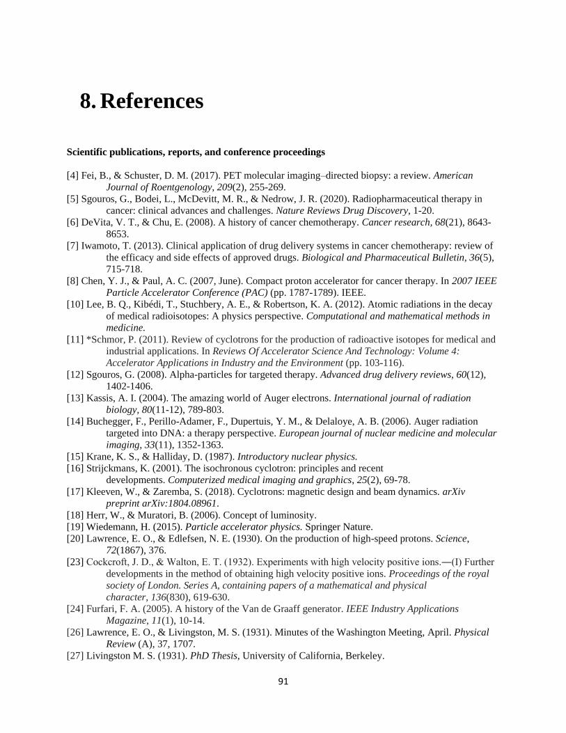
91
8. References
Scientific publications, reports, and conference proceedings
[4] Fei, B., & Schuster, D. M. (2017). PET molecular imaging–directed biopsy: a review. American
Journal of Roentgenology, 209(2), 255-269.
[5] Sgouros, G., Bodei, L., McDevitt, M. R., & Nedrow, J. R. (2020). Radiopharmaceutical therapy in
cancer: clinical advances and challenges. Nature Reviews Drug Discovery, 1-20.
[6] DeVita, V. T., & Chu, E. (2008). A history of cancer chemotherapy. Cancer research, 68(21), 8643-
8653.
[7] Iwamoto, T. (2013). Clinical application of drug delivery systems in cancer chemotherapy: review of
the efficacy and side effects of approved drugs. Biological and Pharmaceutical Bulletin, 36(5),
715-718.
[8] Chen, Y. J., & Paul, A. C. (2007, June). Compact proton accelerator for cancer therapy. In 2007 IEEE
Particle Accelerator Conference (PAC) (pp. 1787-1789). IEEE.
[10] Lee, B. Q., Kibédi, T., Stuchbery, A. E., & Robertson, K. A. (2012). Atomic radiations in the decay
of medical radioisotopes: A physics perspective. Computational and mathematical methods in
medicine.
[11] *Schmor, P. (2011). Review of cyclotrons for the production of radioactive isotopes for medical and
industrial applications. In Reviews Of Accelerator Science And Technology: Volume 4:
Accelerator Applications in Industry and the Environment (pp. 103-116).
[12] Sgouros, G. (2008). Alpha-particles for targeted therapy. Advanced drug delivery reviews, 60(12),
1402-1406.
[13] Kassis, A. I. (2004). The amazing world of Auger electrons. International journal of radiation
biology, 80(11-12), 789-803.
[14] Buchegger, F., Perillo-Adamer, F., Dupertuis, Y. M., & Delaloye, A. B. (2006). Auger radiation
targeted into DNA: a therapy perspective. European journal of nuclear medicine and molecular
imaging, 33(11), 1352-1363.
[15] Krane, K. S., & Halliday, D. (1987). Introductory nuclear physics.
[16] Strijckmans, K. (2001). The isochronous cyclotron: principles and recent
developments. Computerized medical imaging and graphics, 25(2), 69-78.
[17] Kleeven, W., & Zaremba, S. (2018). Cyclotrons: magnetic design and beam dynamics. arXiv
preprint arXiv:1804.08961.
[18] Herr, W., & Muratori, B. (2006). Concept of luminosity.
[19] Wiedemann, H. (2015). Particle accelerator physics. Springer Nature.
[20] Lawrence, E. O., & Edlefsen, N. E. (1930). On the production of high-speed protons. Science,
72(1867), 376.
[23] Cockcroft, J. D., & Walton, E. T. (1932). Experiments with high velocity positive ions.―(I) Further
developments in the method of obtaining high velocity positive ions. Proceedings of the royal
society of London. Series A, containing papers of a mathematical and physical
character, 136(830), 619-630.
[24] Furfari, F. A. (2005). A history of the Van de Graaff generator. IEEE Industry Applications
Magazine, 11(1), 10-14.
[26] Lawrence, E. O., & Livingston, M. S. (1931). Minutes of the Washington Meeting, April. Physical
Review (A), 37, 1707.
[27] Livingston M. S. (1931). PhD Thesis, University of California, Berkeley.

92
[28] Chu W. T. (2005). paper LBNL-59884, University of California, Berkeley.
[30] Tobias, C. A., Jones, H. B., Lawrence, J. H., & Hamilton, J. G. (1949). The uptake and elimination
of krypton and other inert gases by the human body. The Journal of clinical investigation, 28(6),
1375-1385.
[31] Wilson, R. R. (1946). Radiological use of fast protons. Radiology, 47(5), 487-491.
[32] Friesel, D. L., & Antaya, T. A. (2009). Medical cyclotrons. In Reviews Of Accelerator Science And
Technology: Volume 2: Medical Applications of Accelerators (pp. 133-156).
[33] Panofsky, W. K. H., & Breidenbach, M. (1999). Accelerators and detectors. In More Things in
Heaven and Earth (pp. 203-222). Springer, New York, NY.
[34] Herr, W. (2003). Beam-beam interactions, CAS-CERN Accelerator School: Intermediate course on
accelerator physics, Zeuthen, Germany.
[35] Thabet, A. A., Hamzawy, A., & Badawi, M. S. (2020). New mathematical approach to calculate the
geometrical efficiency using different radioactive sources with gamma-ray cylindrical shape
detectors. Nuclear Engineering and Technology, 52(6), 1271-1276.
[36] Schwinger, J. (1949). On the classical radiation of accelerated electrons. Physical review, 75(12),
1912.
[37] Tigner, M. (1965). A possible apparatus for electron clashing-beam experiments. Il Nuovo Cimento
(1955-1965), 37(3), 1228-1231.
[38] Jongen, Y., & Genin, F. (2008). U.S. Patent No. 7,446,490. Washington, DC: U.S. Patent and
Trademark Office.
[40] Sigg, P. K. (2006). RF for cyclotrons.
[41] Clark, D. J. (1981). Ion sources for cyclotrons. In the Proceedings of the 9th International
Conference on Cyclotrons and their Applications. September 1981, Caen, France.
[42] Kim, J. H. (2015). Numerical Simulation of a Multi-Cusp Ion Source for High Current H-Cyclotron
at RISP. Physics Procedia, 66, 498-505.
[43] Glenn Research Centre (2019). Cyclotron Operation.
[44] Feng, W., Tao, C., Tianjue, Z., Xianlu, J., Xingzhi, Z., & Zhenguo, L. (2013). Radiation shielding
design for medical cyclotron. Proceedings of IPAC2013, Shanghai, China. JACoW—Creative
Commons Attribution, 3339-3341.
[45] *IAEA (2009). Cyclotron Produced Radionuclides: Guidelines for Setting up a Facility. IAEA
Technical Report, 471.
[46] Chaudhri, M. A., & Boettger, O. (1971, January). DESIGN SPECIFICATIONS FOR COMPACT
CYCLOTRONS. In pp 545-55 of Fifth International Cyclotron Conference./McIlroy, RW (ed.).
London Butterworths (1971). Hammersmith Hospital, London.
[49] Vega C, H. R., Méndez, R., Iñiguez, M. P., Climent, J. M., Peñuelas, I., & Barquero, R. (2006).
Neutron field inside a PET Cyclotron vault room. Retrieved from:
https://inis.iaea.org/collection/NCLCollectionStore/_Public/38/013/38013751.pdf
[50] Vallabhajosula, S., Solnes, L., & Vallabhajosula, B. (2011, July). A broad overview of positron
emission tomography radiopharmaceuticals and clinical applications: what is new?. In Seminars
in nuclear medicine (Vol. 41, No. 4, pp. 246-264). WB Saunders.
[52] Teh, B. S., Woo, S. Y., & Butler, E. B. (1999). Intensity modulated radiation therapy (IMRT): a new
promising technology in radiation oncology. Oncologist, 4(6), 433-442.
[53] Snyder, H. (2019). Literature review as a research methodology: An overview and
guidelines. Journal of Business Research, 104, 333-339.
[54] Palmatier, R. W., Houston, M. B., & Hulland, J. (2018). Review articles: Purpose, process, and
structure. Journal of the Academy of Marketing Science, 46, 1–5.
https://doi.org/10.1007/s11747-017-0563-4.
[55] *Zaremba, S. (2006). Magnets for cyclotrons.
[57] * Sabaiduc, V., Boiesan, T., Carlson, M., Du, D., Piazza, L. A. C., Ryjkov, V., ... & Suthanthiran, K.
(2017, January). BEST 70P Cyclotron Commissioning at INFN LN Legnaro. In 21st Int. Conf.

93
on Cyclotrons and Their Applications (Cyclotrons' 16), Zurich, Switzerland, September 11-16,
2016 (pp. 241-243). JACOW, Geneva, Switzerland.
[58] *International Atomic Energy Agency (IAEA). (2017). For Acquisition of a Solid Target System.
Report Project number: ROM6017.
[59] *Kazarinov, N., Ivanenko, I., & Osswald, F. (2018, June). Beam Extraction from TR24 Cyclotron at
IPHC. In 9th Int. Particle Accelerator Conf.(IPAC'18), Vancouver, BC, Canada, April 29-May
4, 2018 (pp. 3218-3220). JACOW Publishing, Geneva, Switzerland.
[60] *Zyuzin, A., Watt, R., Gyles, B., Erdman, K., & van Lier, E.J. (2012). Advances at ACSI: High
Current TR19 and the new TR24 Cyclotron capabilities and operational experience. Nuclear
Medicine Review, 15, A22-A23.
[61] * Milton, B. F., & Triumf. (1991). Commissioning and First Operation of a 500 [mu] A, 30 MeV,
H↑-Cyclotron: the TR30 (No. DOE/ER/40607--1-VOL. 1). Triumf.
[63] * Gold, G., Johnson, R. R., Milton, B. F., & Sabaiduc, V. (2012). Simulation and Design of a 70MeV
Cyclotron RF System. Proceedings of IPAC.
[65] * Forton, E., Abs, M., Kleeven, W., Neuveglise, D., Zaremba, S., & Nactergal, B. (2010). Design of
IBA CYCLONE® 30XP cyclotron magnet. Cyclotrons 2010—Proceedings.
[66] *Kleeven, W., Abs, M., Forton, E., Neuveglise, D., Zaremba, S., Nactergal, B., & Servais, T. (2010).
UPGRADE OF IBA CYCLONE® 3 CYCLOTRON.
[67] * Nuttens, V., Abs, M., Kleeven, W., Nactergal, B., Neuveglise, D., Servais, T., & Zaremba, S.
(2010). DESIGN OF IBA CYCLONE® 11 CYCLOTRON MAGNET. Cyclotrons 2010—
Proceedings.
[68] * Conard, E., Morelle, J. L., Clark, J. C., & Mackay, D. B. (1992). Experiences with the Cyclone 3
Oxygen 15 Generator. In Proceedings of the 13th International Conference on Cyclotrons and
Their Applications (p. 218).
[69] * Mukherjee, B. (1998). Occupational Radiation Exposure at The Self-Shielded IBA Cyclone 10/5
Cyclotron of The A&RMC, Melbourne Australia.
[70] * Pearson, E., Abs, M., Henrotin, S., Kleeven, W., Van de Walle, J., Verbruggen, P., & Zaremb, S.
(2013). The new IBA superconducting synchrocyclotron (S2C2): from modeling to reality. In
Proc. AccApp, 11th Int. Topical Meeting on Nuclear Application of Accelerators.
[71] * Smirnov, V., & Vorozhtsov, S. (2016). Modern compact accelerators of cyclotron type for medical
applications. Physics of Particles and Nuclei, 47(5), 863-883.
[74] * Kim, Y. S., An, D. H., Chai, J. S., Chang, H. S., Hong, B. H., Hong, S. S., ... & Kim, J. H. (2004).
New Design of the KIRAMS-13 cyclotron for regional cyclotron center. In Proceedings of
APAC (pp. 338-340).
[75] * Jung, I. S., An, D. H., Chai, J. S., Chang, H. S., Hong, B. H., Hur, M. G., ... & Yang, T. K. (2004).
Design of KIRAMS-13 RF system for regional cyclotron center. Power (kW), 36, 12.
[76] * Jung, I. S., Kang, G. U., An, D. H., Hahn, G., Kang, J. S., Hwan, B., ... & Yang, T. G. (2010).
Development of a Beam Buncher for the KIRAMS-30 Cyclotron. Journal of the Korean
Physical Society, 56(6), 1960-1963.
[77] * Kang, K. U., An, D. H., Chang, H. S., & Chai, J. S. (2008). Performance optimization of H−
multicusp ion source for KIRAMS-30 cyclotron. Review of Scientific Instruments, 79(2),
02A522.
[79] * Liu, Y. H., Sheu, R. J., Chang, J. C., Yin, K. W., & Jiang, S. H. (2006). A study on the [18F] FDG
production efficiency of the MINItrace™ cyclotron in Shin Kong Memorial Hospital. Nuclear
Instruments and Methods in Physics Research Section A: Accelerators, Spectrometers,
Detectors and Associated Equipment, 562(2), 1064-1067.
[80] * Hall, A. C. (2019). Development of a Model for 11 C Production via the 14 N (p, α) Reaction
Using a GE Pettrace Cyclotron.
[81] * Asp, J., Santos, A. M. C., Moghaddasi, L., Afshar, S. V., & Bezak, E. (2020). Design and
verification of an external radiobiological beam port on a 16.5 MeV GE PETtrace proton
cyclotron. Medical Physics, 47(2), 393-403.

94
[82] * Bosko, A., Zhilchenkov, D., & Reece, W. D. (2004). GE PETtrace cyclotron as a neutron source
for boron neutron capture therapy. Applied radiation and isotopes, 61(5), 1057-1062.
[84] * Blosser, H., Gelbke, G. K., Lawton, D., Marti, F., Vincent, J., York, R. C., & Zellr, A. (1993).
Proposal for a manufacturing prototype superconducting cyclotron for advanced cancer
therapy. MSUCL-874, East Lansing, Mi USA.
[85] * Röcken, H., Abdel-Bary, M., Akcöltekin, E., Budz, P., Stephani, T., & Wittschen, J. (2010). The
VARIAN 250 MeV superconducting compact proton cyclotron: medical operation of the 2nd
machine, production and commissioning status of machines No. 3 to 7. Proceedings of
Cyclotrons 2010.
[87] * Bricault, P., Dombsky, M., Kunz, P., Lassen, J., Ames, F., & Hanemaayer, V. (2010). Progress
towards new RIB and higher intensities at TRIUMF. CYCLOTRONS.
[88] * Yano, Y. (2007, June). Status of the RIKEN RIB Factory. In 2007 IEEE Particle Accelerator
Conference (PAC) (pp. 700-702). IEEE.
[89] * Bandyopadhyay, A., Bhowmick, D., Basak, S., Chakrabarti, A., Chauhan, P. S., Dechoudhury, S.,
... & Pandey, H. K. (2009). Rare Ion Beam Facility At Kolkata-Present State Of Development.
In PAC (Vol. 9, p. 5053).
[90] * International Atomic Energy Association. (2008). Cyclotron produced radionuclides: Principles
and Practice. Technical Reports Series no, 465. Vienna, Austria.
[91] * Schlyer, D. J., Van den Winkel, P., Ruth, T. J., Vora, M. M., Pillai, M., & Haji-Saeid, M. (2008).
Cyclotron produced radionuclides: Principles and practice. IAEA Technical Reports Series, 465.
[92] *International Atomic Energy Agency (2006). Directory of Cyclotrons used for Radionuclide
Production in Member States 2006 Update, IAEA Technical Report IAEA-DCRP/2006,
Vienna.
[93] * Brown, I. G. (Ed.). (2004). The physics and technology of ion sources. John Wiley & Sons.
[94] *International Atomic Energy Association. (2009). Cyclotron produced radionuclides: physical
characteristics and production methods. Technical Reports Series no., 468, 53-62.
[96] * Gutfilen, B., Souza, S. A., & Valentini, G. (2018). Copper-64: a real theranostic agent. Drug
design, development and therapy, 12, 3235.
[97] * Zhou, Y., Li, J., Xu, X., Zhao, M., Zhang, B., Deng, S., & Wu, Y. (2019). 64Cu-based
radiopharmaceuticals in molecular imaging. Technology in cancer research & treatment, 18,
1533033819830758.
[98] * Peach, M. S., Dutta, S. W., Bauer-Nilsen, K., Campbell, D., Libby, B., & Showalter, T. N. (2018).
Palladium-103 (Pd-103) Prostate Cancer Brachytherapy: Long-Term Outcomes in over 700
Patients. International Journal of Radiation Oncology• Biology• Physics, 102(3), e133-e134.
[99] * Soundararajan, A., Bao, A., Phillips, W. T., McManus, L. M., & Goins, B. A. (2011).
Chemoradionuclide therapy with 186re-labeled liposomal doxorubicin: toxicity, dosimetry, and
therapeutic response. Cancer Biotherapy and Radiopharmaceuticals, 26(5), 603-614.
95
Websites and URL references
[1] European Commission (2019). EU policy on cancer Mission Letter. Retrieved on 2, November 2020,
from: https://ec.europa.eu/commission/commissioners/sites/comm-
cwt2019/files/commissioner_mission_letters/mission-letter-stella-kyriakides_en.pdf
[2] European Commission (n.d.). Cancer. Retrieved from:
https://ec.europa.eu/health/non_communicable_diseases/cancer_en
[3] European Commission (2017). State of health in the EU. Cyprus Country Health Profile 2017.
Retrieved from: http://www.euro.who.int/__data/assets/pdf_file/0007/355975/Health-Profile-
Cyprus-Eng.pdf?ua=1
[9] Darwyne, A. (2020, February 17). Advanced Oncotherapy sells €50m proton therapy system to
Cyprus hospital. Vox Market. https://www.voxmarkets.co.uk/articles/advanced-oncotherapy-
sells-50m-proton-therapy-system-to-cyprus-hospital-3449f2d/
[21] CERN (2020). Future Circular Collider. Retrieved from:
https://home.cern/science/accelerators/future-circular-collider
[22] CERN. (2020). The Large Hadron Collider. CERN Accelerating Science.
https://home.cern/science/accelerators/large-hadron-collider
[25] Adliene, D. (2017). Particle Generators/Accelerators. Erasmus + Report. Retrieved from:
https://ec.europa.eu/programmes/erasmus-plus/project-result-content/ac05b07f-7433-4058-
8317-47bf89e0104e/Particle%20Generators%20Accelerators.pdf
[29] Lynn, Y. (n.d.). An Historical Perspective on the Lab's Legacy. Berkeley Lab. Retrieved from:
https://www2.lbl.gov/Publications/75th/files/04-lab-history-pt-3.html
[39] Clarke, C. (n.d.). Production of radioisotopes. Radiology Cafe. Retrieved November 2, 2020, from
https://www.radiologycafe.com/radiology-trainees/frcr-physics-notes/production-of-
radioisotopes
[47] Cyprus Ministry of Health (2017). Cyprus Cancer Archive [Αρχείο Καρκίνου Κύπρου]. Retrieved
from:https://www.moh.gov.cy/moh/moh.nsf/All/82B40CE2FEE19D7AC22579C6002CBFAD?
OpenDocument
[48] Cyprus Ministry of Health (n.d.). Manual Procedure Recording [In Greek: Εγχειρίδιο Οδηγιών
Καταγραφής Καρκίνου].
[51] Bank of Cyprus Oncology Centre (2017). What is radiotherapy? Retrieved from:
http://www.bococ.org.cy/en/radiation-oncology
[56] * Advanced Cyclotron Systems, Inc. (ASCI). Website: https://www.advancedcyclotron.com/
[62] * Best Cyclotrons Systems Inc (BCSI). Website: http://www.bestcyclotron.com/
[64] * IBA Radiopharmasolutions. Website: https://iba-worldwide.com/about-iba
[72] * IBA. The Superconducting Synchrocyclotron Project S2C2. Retrieved from:
https://indico.cern.ch/event/286275/contributions/651650/attachments/531390/732777/Part-
4.pdf
[73] * Kirams. Website: https://www.kirams.re.kr/eng/
[78] * GE Healthcare. Website: https://www.gehealthcare.se/
[83] * VARIAN. Website: https://www.varian.com/products/proton-therapy/treatment-delivery/probeam-
360.
[86] * Varian Medical Systems (2013). Superconducting Cyclotrons: A medical device manufacturer’s
view. Retrieved from:
https://indico.cern.ch/event/234471/contributions/495950/attachments/391969/545108/Schillo.p
df
[95] * Business Wire (2019). Global Medical Cyclotron Market 2020-2024 | Evolving Opportunities with
ALCEN and Ebco Industries Ltd. | Technavio. Retrieved:
https://www.businesswire.com/news/home/20191127005111/en/