A review of additive manufacturing technology and its ...
16
249 CHINA FOUNDRY Vol. 18 No. 4 July 2021 Special Review A review of additive manufacturing technology and its application to foundry in China https://doi.org/10.1007/s41230-021-1003-0 Shi-yan Tang, Li Yang, *Zi-tian Fan, Wen-ming Jiang, Xin-wang Liu State Key Laboratory of Materials Processing and Die & Mould Technology, School of Materials Science and Engineering, Huazhong University of Science and Technology, Wuhan 430074, China Abstract: The application of additive manufacturing technology is one of the main approaches to achieving the rapid casting. Additive manufacturing technology can directly prepare casting molds (cores) with no need of patterns, and quickly cast complex castings. The combination of additive manufacturing and traditional casting technology can break the constraint of traditional casting technology, improve casting flexibility, and ameliorate the working environment. Besides, additive manufacturing promotes the realization of “free casting”, greatly simplifying the processing procedures and shortening the manufacturing cycle. This paper summarizes the basic principle of additive manufacturing technology and its development situation domestically and overseas, mainly focusing on the development status of several main additive manufacturing technologies applicable to the foundry field, including three-dimensional printing, selective laser sintering, stereolithography, layered extrusion forming, etc. Finally, the future development trend of additive manufacturing technology in the foundry field is prospected. Key words: additive manufacturing; rapid prototyping; 3D printing; casting process; rapid casting CLC numbers: TG221; Document code: A; Article ID: 1672-6421(2021)04-249-16 1 Introduction Additive manufacturing (AM), previously known as rapid prototyping manufacturing (RPM), and is now publicized as three-dimensional printing (3DP). It is based on the dispersed-accumulated forming principle. According to the height of the discrete direction, the 3D part is transformed into a series of simple units, and the materials are processed layer by layer and stacked into the whole parts by the forming machine. Research on additive manufacturing technology started in the early 1980s [1] . Additive manufacturing technology was developed by Charles W. Hull in 1986 [2] in a process known as stereolithography (SL), and was later commercialized by 3D Systems Inc. Deckard [3] at the University of Texas at Austin invented selective laser sintering (SLS), with the first patent filed in 1989. Sachs et al. [4] at the Massachusetts Institute of Technology (MIT) filed a patent for 3D printing (3DP) in 1989 and published in 1993. Fused deposition modeling (FDM) was invented by Crump et al. with a patent published in 1992 [5] . Direct ink writing (DIW), also known as layered extrusion forming and robocasting, was first filed as a patent by Cesarano et al. in 1997 and published in 2000 [6] . Overseas companies based on the concept of “additive manufacturing” have emerged and developed rapidly during the past decades, including American companies such as Stratasys, 3D Systems, and ExOne, and German companies such as Voxeljet and SLM Solutions [7] . In the draft of the National Industrial Strategy 2030 issued by the Ministry of Economy and Energy of Germany in 2019, additive manufacturing was listed as one of the “key industrial sectors” in the ten industrial fields. The aviation enterprises represented by GE of the United States plan to use 10,000 sets of metal printers in 2021, which shows the subversive significance of additive manufacturing technology [8] . *Zi-tian Fan Professor, Doctoral Supervisor. Prof. Fan is now the Vice Dean of School of Materials Science and Engineering, Huazhong University of Science and Technology (HUST). His research interests mainly focus on Al-Mg alloy materials and precision casting technology, green foundry technology and theory, 3D printing rapid casting technology, etc. Professor Fan has presided over the completion of more than 20 projects, including the projects supported by the National Natural Science Foundation of China and the National “863” Program. He has published more than 480 research papers in journals and international conferences, 12 books and textbooks, and possesses 36 China Patents for Invention. Prof. Fan is also the Vice President of the Foundry Institution of Chinese Mechanical Engineering Society, and the Deputy Director of the Foundry Branch of the Materials Forming and Control Engineering Teaching Committee of China. E-mail: [email protected] Received: 2021-05-18 Accepted: 2021-07-15
Transcript of A review of additive manufacturing technology and its ...

249
CHINA FOUNDRYVol. 18 No. 4 July 2021Special Review
A review of additive manufacturing technology and its application to foundry in China
https://doi.org/10.1007/s41230-021-1003-0
Shi-yan Tang, Li Yang, *Zi-tian Fan, Wen-ming Jiang, Xin-wang LiuState Key Laboratory of Materials Processing and Die & Mould Technology, School of Materials Science and Engineering, Huazhong University of Science and Technology, Wuhan 430074, China
Abstract: The application of additive manufacturing technology is one of the main approaches to achieving the rapid casting. Additive manufacturing technology can directly prepare casting molds (cores) with no need of patterns, and quickly cast complex castings. The combination of additive manufacturing and traditional casting technology can break the constraint of traditional casting technology, improve casting flexibility, and ameliorate the working environment. Besides, additive manufacturing promotes the realization of “free casting”, greatly simplifying the processing procedures and shortening the manufacturing cycle. This paper summarizes the basic principle of additive manufacturing technology and its development situation domestically and overseas, mainly focusing on the development status of several main additive manufacturing technologies applicable to the foundry field, including three-dimensional printing, selective laser sintering, stereolithography, layered extrusion forming, etc. Finally, the future development trend of additive manufacturing technology in the foundry field is prospected.
Key words: additive manufacturing; rapid prototyping; 3D printing; casting process; rapid casting
CLC numbers: TG221; Document code: A; Article ID: 1672-6421(2021)04-249-16
1 IntroductionAdditive manufacturing (AM), previously known as rapid prototyping manufacturing (RPM), and is now publicized as three-dimensional printing (3DP). It is based on the dispersed-accumulated forming principle. According to the height of the discrete direction, the 3D part is transformed into a series of simple units, and the materials are processed layer by layer and stacked into the whole parts by the forming machine.
Research on additive manufacturing technology started in the early 1980s [1]. Additive manufacturing technology was developed by Charles W. Hull in 1986 [2] in a process known as stereolithography (SL), and was later commercialized by 3D Systems Inc. Deckard [3] at the University of Texas at Austin invented selective laser sintering (SLS), with the first patent filed in 1989. Sachs et al. [4] at the Massachusetts Institute of Technology (MIT) filed a patent for 3D printing (3DP) in 1989 and published in 1993. Fused deposition modeling (FDM) was invented by Crump et al. with a patent published in 1992 [5]. Direct ink writing (DIW), also known as layered extrusion forming and robocasting, was first filed as a patent by Cesarano et al. in 1997 and published in 2000 [6]. Overseas companies based on the concept of “additive manufacturing” have emerged and developed rapidly during the past decades, including American companies such as Stratasys, 3D Systems, and ExOne, and German companies such as Voxeljet and SLM Solutions [7]. In the draft of the National Industrial Strategy 2030 issued by the Ministry of Economy and Energy of Germany in 2019, additive manufacturing was listed as one of the “key industrial sectors” in the ten industrial fields. The aviation enterprises represented by GE of the United States plan to use 10,000 sets of metal printers in 2021, which shows the subversive significance of additive manufacturing technology [8].
*Zi-tian FanProfessor, Doctoral Supervisor. Prof. Fan is now the Vice Dean of School of Materials Science and Engineering, Huazhong University of Science and Technology (HUST). His research interests mainly focus on Al-Mg alloy materials and precision casting technology, green foundry technology and theory, 3D printing rapid casting technology, etc. Professor Fan has presided over the completion of more than 20 projects, including the projects supported by the National Natural Science Foundation of China and the National “863” Program. He has published more than 480 research papers in journals and international conferences, 12 books and textbooks, and possesses 36 China Patents for Invention. Prof. Fan is also the Vice President of the Foundry Institution of Chinese Mechanical Engineering Society, and the Deputy Director of the Foundry Branch of the Materials Forming and Control Engineering Teaching Committee of China.
E-mail: [email protected]
Received: 2021-05-18 Accepted: 2021-07-15

250
CHINA FOUNDRY Vol. 18 No. 4 July 2021Special Review
Since 1990, basic research on additive manufacturing technology has been carried out in China [9-10]. Huazhong University of Science and Technology (HUST) successfully developed the laminated object manufacturing (LOM) printer in the 1990s, and carried out numerous research works on rapid prototyping equipment and materials. Meanwhile, researchers carried out research and development of selective laser sintering equipment. Tsinghua University successfully developed a “M-RPMS type multifunctional rapid prototyping manufacturing system”. Xi'an Jiaotong University also carried out various research works on stereolithography apparatus and materials, and Beijing Longyuan AFS Co., Ltd. obtained achievements on the selective laser sintering materials and process. Although domestic studies on additive manufacturing technology started relatively late compared with foreign research, it has developed rapidly. For example, since 2012, Kocel [11] realized the localization of 3D printing materials, process, software and equipment for casting, and built a 10,000-ton foundry 3D printing factory, which provided a solution for the transformation and upgrading of the traditional foundry industry. However, the core component in the 3DP system still needs to be conquered.
After nearly 40 years of development, AM technology shows great significance in machinery manufacturing, aerospace, automotive, metal casting, biological, medical, food, footwear, clothing, and building industries, which helps to break through the traditional manufacturing mode. Furthermore, with increasingly evolution of AM technology, its application fields keep on expanding, covering a wide range of raw materials, including plastics, metals, ceramics, etc [12-14].
Combining AM technology with traditional casting technology can give full play to the technical advantages of AM and improve the casting flexibility, thus greatly reducing the cost of product R&D and innovation, shortening the
period of innovation and improving the direct success rate of production [15], and therefore, promoting the development and transformation of traditional casting.
Many researchers have been studying the application of AM technology in the field of traditional casting since the 1990s [16]. For example, the Pratt & Whitney Laboratory in the United States produced 2,000 castings with 3D printing technology in 1994 [10]. During the same period, Huazhong University of Science and Technology, Tsinghua University, Beijing Longyuan AFS Co., Ltd., Xi'an Jiaotong University, and others, also began the research work of rapid casting technology [17-18]. For instance, Fan et al. [19] used the self-developed SLS system to prepare coated sand trial castings in 1998.
Currently, AM technologies applied to casting mainly include 3D printing, selective laser sintering, and stereolithography[20-21]. This paper focuses on the mechanism and state-of-the-art development in metal casting of the abovementioned AM technologies, and prospects the future development of the rapid casting field.
2 Three-dimensional printing (3DP)The 3DP method was first invented by Sachs et al. at the MIT, who filed a patent for it in 1989 [4]. Since then, 3DP has been applied to rapid casting. Tsinghua University proposed patternless casting manufacturing (PCM) based on upper spray bonding molding. Currently, well-developed 3DP equipment companies mainly include ExOne in the United States, Voxeljet in Germany, and KOCEL Co., Ltd., Guangdong Fenghua Zhuoli Technology Co., Ltd. (FHZL), Wuhan Easymade Technology Co., Ltd. (EASYMFG) in China. Table 1 shows some typical 3DP equipment parameters in different companies.
Table 1: Representative companies based on 3DP technique [7, 22-24]
Company Type Build size(L×W×H) (mm3) Resolution (dpi) Layer thickness
(mm) Number of nozzles
ExOne
Innovent Platform 160×65×65 400×400 0.1 -
S-Print Platform 800×500×400 400×400 0.28-0.5 -
Exerial Platform 2,200×1,200×600 300×300 0.28-0.5 -
Voxeljet
VX200 300×200×150 300×300 0.15 256
VXC800 850×500×300 600×600 0.15-0.4 2,656
VX4000 4,000×2,000×1,000 600×600 0.12-0.3 26,560
KOCEL
AJS 1000A 1,000×600×500 400×400 0.2-0.5 -
AJS 2500A 2,600×2,000×1,000 300×300 -
AJD 2500B 2,500×1,800×1,000×2 ≥300 -
FHZL
PCM300 300×250×250300×300 or
400×400
0.2-0.5 1×1,024 P
PCM1200 1,200×1,000×600 4×1,024 P
PCM2200 2,200×1,000×800 4×1,024 P
EASYMFG
Easy3DP-S2200 2,000×1,000×600 360 0.1-0.5 -
Easy3DP-M500 500×450×400 600 0.04-0.2 -
Easy3DP-G450 450×220×300 180 0.1-0.2 -

251
CHINA FOUNDRYVol. 18 No. 4 July 2021Special Review
Fig. 1: Typical sand mold (core) prepared by 3DP method
Fig. 2: Flow chart of 3DP-based sand casting process
Hawaldar et al. [29] conducted a comparative study on the traditional sand mold casting process and 3DP formed sand mold casting process. Results showed that the 3DP technology had obvious advantages in preparing sand molds (cores) because it can not only enhance the sand utilization efficiency, but also improve the mechanical properties of the sand molds (cores). Zhao et al. [33] systematically studied the influence of sand angular coefficient, particle size distribution, surface tension and viscosity of binder on axial accuracy and performance of 3DP formed sand mold. It was found that the quality of sand mold formed with an angular coefficient of 1.1 showed superior quality; the axial dimension deviation along X, Y and Z directions was 0.18 mm, 0.11 mm and -0.04 mm, respectively; and the tensile strength of the sand mold was 0.88 MPa. Figure 3 shows the bonding morphology of sand particles with different sand particle size, layer thickness and binder injection amount. It can be revealed from Fig. 3 that a smaller sand particle size, a smaller layer thickness and a
greater amount of binder injection led to a tighter connection between the sand particles, and therefore, a higher tensile strength.
Deng et al. [34] adopted the 3DP method to prepare complex furan resin sand molds with and without the air cavity surrounding the riser (Fig. 4) to verify the insulation effect of the air cavity. The analysis of heat transfer inside the air cavity indicated the presence of the air cavity led to a 12.5% increase of the solidification time of the riser. The designed sand mold for casting with an air cavity surrounding the riser can be prepared by 3DP method quickly with no need of patterns, which enhances production efficiency.
Based on the solvent method, Tian et al. [35] tried to form sand molds (cores) by 3DP. This process changes the traditional “viscous resin-based binder” into “solvent based binder”, which possesses good stability and facilitates solving the nozzle clogging problem. An ethanol-based binder containing polyethylene glycol molecules was adopted. The
In the process of 3DP, a binder solution in droplet form is sprayed through printheads onto selected regions of a powder bed surface. Solid layers are formed by the solidification of the permeating liquid binder, which encloses the powder. A new layer of powder is then supplied and spread on the previous layer to repeat the building process until the part is built. After this, loose powder is removed to obtain the green body [25-27]. At present, the application of 3DP in casting is mainly to prepare a sand mold (core) and ceramic shell (core).
2.1 3DP sand mold (core)Traditional sand casting mold making processes involve the fabricating of a pattern, mixing the sand and binder, and then pouring the mixture into a wood or metal mold to shape pieces for
a sand mold assembly. Subsequently, the molten metal is poured into the sand mold to obtain final metal castings [7]. The process is considered complicated and high energy consumming. Recently, fabrication of sand molds based on 3DP method has been developed, which has changed the production mode of the casting industry. The sand mold can be directly rapidly formed without patterns, improving the production efficiency of metal castings [28-30]. Some sand mold (core) samples prepared by 3DP method are shown in Fig. 1.
Figure 2 shows the 3DP sand casting process, mainly including the structure designing, 3D printing, assembling, and casting procedures. Normally, the molding sand mainly includes silica sand, zirconium sand, etc., and the binder mainly includes furan resin, phenolic resin, inorganic binder, etc [31-32].

252
CHINA FOUNDRY Vol. 18 No. 4 July 2021Special Review
Fig. 3: Bonding morphology of sand particles with different particle size, layer thickness and binder injection amount: (a) 70-140 mesh, 0.32 mm, 10%; (b) 70-140 mesh, 0.32 mm, 5%; (c) 140-200 mesh, 0.12 mm, 10%; (d) 140-200 mesh, 0.12 mm, 25% [33]
Fig. 4: Furan resin sand mold printed by 3DP technology without (a) and with (b) air cavity surrounding the riser [34]
(a) (b)
(c) (d)
results revealed that as the ethanol addition increased, the tensile strength of the sand molds increased. As the ethanol content was 90%, and the layer thickness was 0.25 mm, the prepared sand molds possessed the initial green and post-processing tensile strength of 0.48 MPa and 3.787 MPa, respectively. Finally, the 12CrMo turbine part was obtained after casting, which showed no obvious defects after shot pinning.
Li et al. [36] adopted resin dilution and interlayer baking method to effectively reduce the gas generation of the 3DP sand mold. The composition of the raw sand and binder used in this process was basically the same as that of traditional no-bake resin sand, but the viscosity, surface tension and
other physicochemical properties of binder and catalyst were adjusted according to the characteristics of the 3DP process.
The strength of the sand mold formed by 3DP is mainly provided by the binder connecting the sand particles layer by layer to form a cross-linked network structure. Under the same conditions of forming materials, the strength of the sand mold formed by 3DP is lower than that obtained by the traditional process, so, researchers usually increase the amount of binder injection to improve the strength of the casting molds. However, excessively increasing binder injection will lead to flocculation of sand particles, resulting in low accuracy of the sand molds and an increase of porosity defects in castings [26].
(a) (b)

253
CHINA FOUNDRYVol. 18 No. 4 July 2021Special Review
Fig. 5: Photographs of complex-shaped alumina ceramic cores fabricated by an inorganic binder: (a) printing equipment; (b) design drawing of cores; (c) green cores [46]
2.2 3DP ceramic shell (core)As early as 1990, Sachs et al. [4, 37] adopted the 3DP method to prepare alumina-based ceramic shells (cores). Z Corp in US launched “ZCast Direct Metal Casting” technology, and the corresponding ceramic shells were suitable for non-ferrous alloy casting [38]. Gill et al. [39-42] adopted the 3DP method to prepare ceramic shells and carried out Al, Zn and Pd alloy casting. Chhabra et al. [43] prepared Al, brass and Cu castings using the ZCast process based on the 3D printing technique. The experimental average surface roughness was 6.76 µm, 11.27 µm, and 11.56 µm, respectively, which was acceptable comparing to the sand cast surface roughness (6.25-25 µm).
In recent years, high temperature ceramic molds (cores) were prepared by 3DP technology. By spraying inorganic binder onto the ceramic particles, the ceramic molds (cores) with higher strength and lower shrinkage during sintering were
manufactured. Zhao et al. [44-45] systematically studied the effect of nanozirconia-absolute ethyl alcohol solution on the 3DP CaO-based cores. Results showed that increasing the binder saturation level caused a decrease in the linear shrinkage of the sintered parts, but an increase in hydration resistance and bending strength. After sintering at 1,300 °C, the CaO-based cores had a bending strength of 14 MPa and linear shrinkage of 2.11%.
Huang et al. [46] prepared alumina-based cores through the 3DP method (Fig. 5) using zirconium basic carbonate (ZBC) as binder, and the effects of different ZBC contents on the printability of the binder and the performance characteristics of the ceramic cores were investigated. The results revealed that as ZBC content was 35wt.% and sintering temperature was 1,500 °C, the ceramic core obtained had a bending strength of 79 MPa and linear shrinkage of 13%.
Compared with a conventional sand molding process, the 3DP technique greatly shortens the manufacturing periods by omitting the procedures of preparing wood or metal patterns. Besides, unlike other additive manufacturing methods that adopt laser curing or laser sintering or costly photosensitive resin, the 3DP technique adopts common binder and particle material similar as that suitable for conventional sand molding process, which comparatively reduces costs. In addition, the 3DP method shows superiority in the high flexibility of geometrical design without the addition of supports during formation. However, the formed parts are loose and porous, with low strength and rough surface, so necessary post-treatment is required to further improve the accuracy and strength. To fundamentally enhance the precision and strength of 3DP parts, it is necessary to conduct a systematic and in-depth analysis of several key technical issues in the 3DP process, such as the influencing mechanism of spraying parameters, binder properties and curing behavior, the effect of powder material parameters on the accuracy of parts, and the interaction law of the force between the powder layers during the powder spreading process. In addition, 3DP apparatus produced in domestic companies are restricted by the core component “nozzle”, and efforts should be made in future to solve this technical issue.
3 Selective laser sintering (SLS)SLS technology was first proposed by Deckard and Beaman [3], and further developed by the DTM Company. The SLS technique employs a super high-power laser to selectively irradiate the surface of the target powder bed. Under the control of computer programming, the laser selectively scans the material powder surface at a certain scanning speed and energy density, so as to melt the particles and allow sintering to take place for bulk jointing. Then, a new layer of powder is spread onto the previous surface for the next run of heating and joining. In this way, the process is repeated layer by layer until the designed 3D part is finished [47]. After decades of development, the main SLS forming equipment manufacturers now include 3D Systems, EOS, Beijing Longyuan AFS Co., Ltd., Huake 3D Technology Co. Ltd., Farsoon Technologies, etc., as summarized in Table 2.
SLS technology plays an important role in manufacturing complex, light and thin-walled parts. The original intention of SLS was to make wax models for investment casting of metallic prototypes, but recently, SLS has been extended to coated sand and ceramic, as shown in Fig. 6.
(a)
(b) (c)

254
CHINA FOUNDRY Vol. 18 No. 4 July 2021Special Review
Fig. 6: Different materials for parts by SLS technique: (a) coated sand mold; (b) wax pattern; (c) ceramic samples [14]
Table 2: Typical SLS equipment in the world [48-52]
3.1 SLS forming coated sand mold (core)It is an outstanding application of rapid prototyping technology in the foundry industry to use coated sand as sintering material and directly forming the mold (core) for casting by SLS method [9].Compared with the traditional sand-mold casting method, SLS saves tooling equipment (molding and core making machine, transportation equipment, etc.), and the complex and bulky casting production process can be completed on the SLS machine.
SLS research based on using coated sand as matrix material began in Europe in 1996 (such as EOS Company in Germany). The formation process is that heating and melting the binder previously coated on the surface of sand particles, and after cooling and solidifying, the sand particles are bonded together and connection necks among particles are established [53]. The influence of process parameters (laser power, laser spot size, scanning speed, sand preheating temperature, layer thickness, etc.) on the formability of SLS coated sand has always been the focus of research. Fan et al. [9, 54-57] systematically studied the effect of process parameters on a coated sand mold (core) by SLS method, analyzed the curing mechanism and characteristics of coated sand under laser, and obtained a variety of qualified metal castings. The higher sintered strength of the sand
mold (core) would be attained in association with the slower scanning velocity, the greater output power and the thinner thickness. Otherwise, the sintered strength of the sand mold (core) would be lowered.
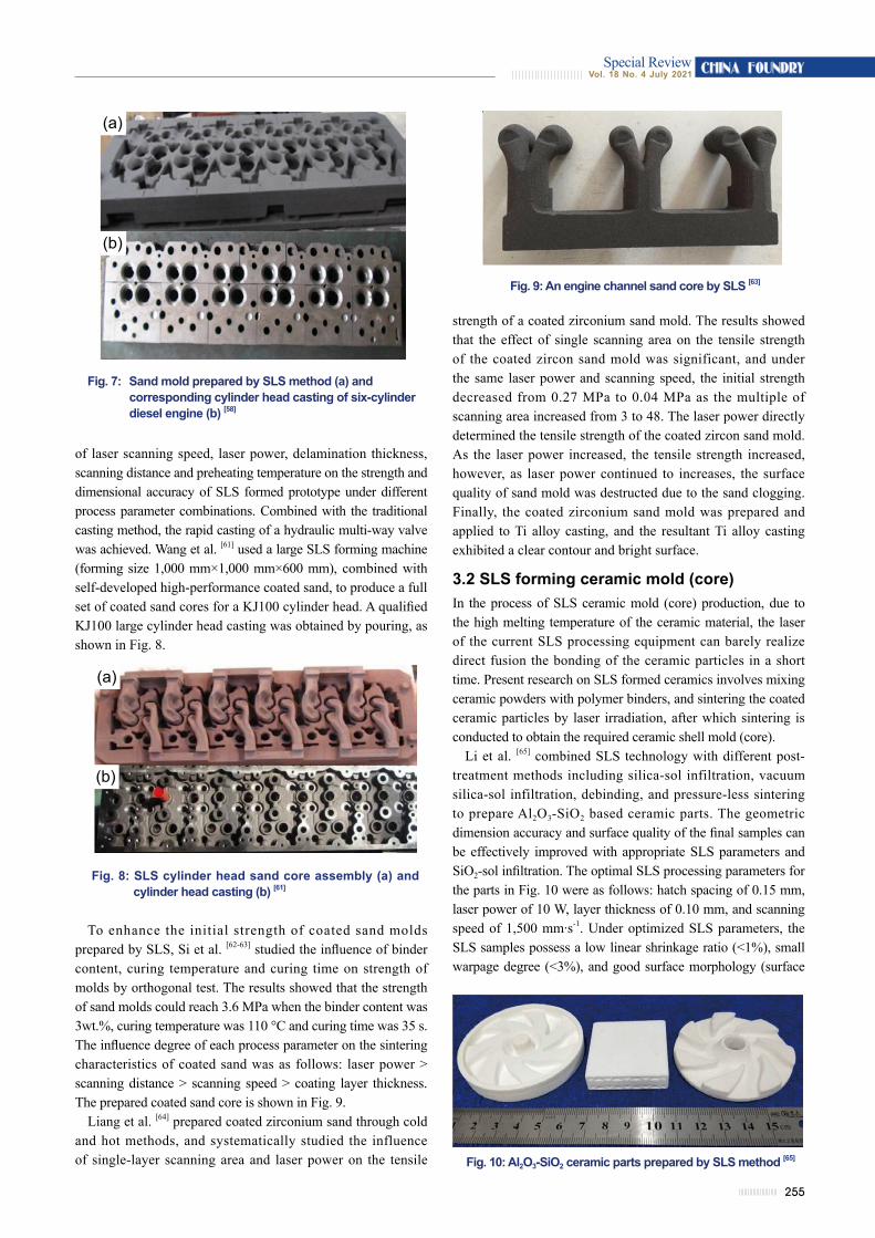
Wen et al. [58] proposed novel binder-coated Al2O3 sands to prepare complex sand molds via SLS for metal casting. The curing mechanisms of the coated sands during the SLS and post-curing processes were studied, and effects of binder content, raw sand type and post-curing parameters on the strength and gas evolution were investigated. Finally, a large sand mold of the cylinder head of a complex six-cylinder diesel engine was successfully prepared and cast, and the casting with surface quality and dimensional accuracy meeting the design requirements was finally obtained. The sand mold and casting are shown in Fig. 7.
Tang et al. [59] adopted silica sand as the matrix material to prepare a casting mold with SLS technology. The effects of process parameters on the precision, strength and surface finish of sintered parts were studied. The compressive strength and surface roughness of sintered parts increase with the increase of laser power and decrease with the increase of scanning speed in the range of 60-180 mm·s-1. Bo et al. [60] analyzed the influence
Manufacturer Model Build volume(mm3) Laser type Layer thickness
(mm)Maximum
scanning speed (m·s-1)
3D SystemssProTM 230 550×550×750 CO2, 70 W 0.08-0.15 10
ProX® SLS 6100 381×330×460 CO2, 70 W 0.08-0.15 12.7
EOS
FORMIGA P 110 Velocis 200×250×330 CO2, 30 W 0.06-0.12 5
EOS P500 500×330×400 CO2, 2×70 W 0.06-0.18 2×10
Longyuan AFSLaserCore-6000 1050×1050×650 CO2, 120 W 0.08-0.35 6
AFS-500 500×500×500 CO2, 55 W or 120 W 0.08-0.35 6
Huake 3D TechnologyHK S1200 1200×1200×600 CO2, 100 W 0.08-0.3 8
HK S320 320×320×450 CO2, 30 W 0.08-0.3 4
Farsoon TechnologiesSS403P 400×400×450 CO2, 100 W 0.06-0.3 15.2
Flight HT252P 250×250×320 Fiber laser, 300 W 0.06-0.3 15
(a) (b) (c)
255
CHINA FOUNDRYVol. 18 No. 4 July 2021Special Review
Fig. 7: Sand mold prepared by SLS method (a) and corresponding cylinder head casting of six-cylinder diesel engine (b) [58]
Fig. 9: An engine channel sand core by SLS [63]
(a)
(b)
of laser scanning speed, laser power, delamination thickness, scanning distance and preheating temperature on the strength and dimensional accuracy of SLS formed prototype under different process parameter combinations. Combined with the traditional casting method, the rapid casting of a hydraulic multi-way valve was achieved. Wang et al. [61] used a large SLS forming machine (forming size 1,000 mm×1,000 mm×600 mm), combined with self-developed high-performance coated sand, to produce a full set of coated sand cores for a KJ100 cylinder head. A qualified KJ100 large cylinder head casting was obtained by pouring, as shown in Fig. 8.
Fig. 8: SLS cylinder head sand core assembly (a) and cylinder head casting (b) [61]
(a)
(b)
strength of a coated zirconium sand mold. The results showed that the effect of single scanning area on the tensile strength of the coated zircon sand mold was significant, and under the same laser power and scanning speed, the initial strength decreased from 0.27 MPa to 0.04 MPa as the multiple of scanning area increased from 3 to 48. The laser power directly determined the tensile strength of the coated zircon sand mold. As the laser power increased, the tensile strength increased, however, as laser power continued to increases, the surface quality of sand mold was destructed due to the sand clogging. Finally, the coated zirconium sand mold was prepared and applied to Ti alloy casting, and the resultant Ti alloy casting exhibited a clear contour and bright surface.
3.2 SLS forming ceramic mold (core)In the process of SLS ceramic mold (core) production, due to the high melting temperature of the ceramic material, the laser of the current SLS processing equipment can barely realize direct fusion the bonding of the ceramic particles in a short time. Present research on SLS formed ceramics involves mixing ceramic powders with polymer binders, and sintering the coated ceramic particles by laser irradiation, after which sintering is conducted to obtain the required ceramic shell mold (core).
Li et al. [65] combined SLS technology with different post-treatment methods including silica-sol infiltration, vacuum silica-sol infiltration, debinding, and pressure-less sintering to prepare Al2O3-SiO2 based ceramic parts. The geometric dimension accuracy and surface quality of the final samples can be effectively improved with appropriate SLS parameters and SiO2-sol infiltration. The optimal SLS processing parameters for the parts in Fig. 10 were as follows: hatch spacing of 0.15 mm, laser power of 10 W, layer thickness of 0.10 mm, and scanning speed of 1,500 mm·s-1. Under optimized SLS parameters, the SLS samples possess a low linear shrinkage ratio (<1%), small warpage degree (<3%), and good surface morphology (surface
To enhance the initial strength of coated sand molds prepared by SLS, Si et al. [62-63] studied the influence of binder content, curing temperature and curing time on strength of molds by orthogonal test. The results showed that the strength of sand molds could reach 3.6 MPa when the binder content was 3wt.%, curing temperature was 110 °C and curing time was 35 s. The influence degree of each process parameter on the sintering characteristics of coated sand was as follows: laser power > scanning distance > scanning speed > coating layer thickness. The prepared coated sand core is shown in Fig. 9.
Liang et al. [64] prepared coated zirconium sand through cold and hot methods, and systematically studied the influence of single-layer scanning area and laser power on the tensile Fig. 10: Al2O3-SiO2 ceramic parts prepared by SLS method [65]

256
CHINA FOUNDRY Vol. 18 No. 4 July 2021Special Review
altitude difference <170 µm) after vacuum silica-sol infiltration, debinding, and pressure-less sintering.
Wei et al. [66] prepared a mullite ceramic shell by SLS, aiming at enhancing ceramic shell strength and avoiding crack defects during preparation. After optimizing process parameters through orthogonal testing, ceramic shell samples with 99.01-172.02 MPa compressive strength were obtained. They also prepared alumina based ceramic cores through SLS technology, and the bending strength of the ceramic core was improved by combining with high temperature sintering. Experimental results showed that the bending strength of the ceramic shell after sintering at 1,600 °C reached 38.03 MPa [67].
3.3 SLS forming investment casting patternsTraditional investment casting mainly includes preparation of wax pattern, assembly of wax pattern, preparation of multi-layer ceramic shell, dewaxing, shell baking, pouring, removal of ceramic shell, and post-treatment of metal castings [68-69]. The production period was considered long and complicated.
SLS technology was adopted to directly form a wax and resin pattern instead of an investment pattern which could break through the design limit of traditional wax patterns and shorten the preparation cycle of a ceramic shell mold, which was another promising application field of SLS technology in the metallic casting field. In the 1990s, SLS was applied to investment precision casting. The technology was developed earlier by DTM Company in the United States, and later, Huazhong University of Science and Technology, Nanjing University of Aeronautics and Astronautics and Beijing Longyuan AFS Co., Ltd. in China also carried out the relevant research works [10, 18, 70].
Polycarbonate (PC) is the first polymer material used in the preparation of investment materials for SLS because of its good laser sintering properties and high strength. However, PC has a high melting point and poor fluidity, which requires a higher roasting temperature. Compared with PC, polystyrene
(PS) and high impact polystyrene (HIPS) are mainly used as raw materials in recent research for preparing investment patterns by SLS because of low thermal deformation temperature and good fluidity [71].
Shi et al. [72-74] adopted post-processing methods including immersing epoxy resin and wax to enhance mechanical properties and surface quality of SLS-formed PS and HIPS structures. The treated molds could be applied to investment casting. As shown in Fig. 11, integral HIPS patterns suitable for investment casting were successfully prepared through SLS technique, and corresponding metal castings were obtained after investment casting.
Özer et al. [75] used polystyrene powder as matrix material to prepare a polymer pattern by SLS technology. After the SLS process, plaster slurry was coated on the surface of the polymer pattern, and the ceramic shell required for casting was obtained by drying, pattern removal and sintering. Compared with traditional technology, the production cycle was shortened and the production cost was reduced. Figure 12 shows the pattern prepared by SLS method and the corresponding castings.
Wang et al. [76] used SLS technology to prepare a wax pattern. After being coated with silica sol/zircon-based slurry on the surface, the wax patterns were dried at 19-25 °C for 24 h. The ceramic shell with the thickness of 5.5 mm was obtained after drying, dewaxing, and sintering, and finally a high-quality complex stainless steel impeller casting was obtained.
Yang et al. [77] carried out the research on the rapid investment casting process of complex surface parts based on SLS technique. Polystyrene was used to prepare the induction wheel resin pattern, and after wax impregnation treatment, the mold shell of the induction wheel was prepared by dip-coating silica sol. Finally, the induction wheel with good internal and external quality was obtained under the mold shell preheating temperature of 1,115 °C and pouring temperature of 1,600 °C.
Fig. 11: HIPS sample formed by SLS for investment casting: (a, b) HIPS sample; (c, d) castings [74]
(a) (b)
(c) (d)

257
CHINA FOUNDRYVol. 18 No. 4 July 2021Special Review
Fig. 12: SLS patterns and casting: (a) images of wax tree and (b) A356 samples after casting [75]
(a) (b)
The average dimension error was 0.17%-0.19%, and the average surface roughness was 0.693 μm.
SLS technology features a high material utilization rate, but the forming parts with loose microstructure are apt to deform due to internal stress. The forming sample surface is rough and porous because of the limited size of powder particle and laser spot. In addition, post-processing is generally necessary to improve the strength and precision of the SLS forming sample to meet the requirements of practical utilization. For example, to improve the strength and surface precision of the sand shell mold (core), it is necessary to repeatedly heat in an oven and conduct surface coating treatment, which can be used to prepare cast steel, cast iron, magnesium alloy, titanium alloy, etc [58, 64, 71, 78]. The dimensional accuracy and surface roughness of castings using coated sand molds are generally up to CT6-8 and 12.5-3.2 µm. The investment patterns are generally treated by infiltrating paraffin wax or resin to improve the strength and surface precision, which can be used to prepare stainless steel casting, aluminum alloy castings, etc [75, 76, 79]. The dimensional accuracy of obtained castings is generally up to CT6, and the surface roughness is generally below 6.3 µm. However, the preparation of investment patterns instead of the wax patterns
based on SLS technology can only be used to form ceramic shells indirectly. The surface of an investment pattern needs to be dip-coated multiple times to obtain the ceramic shell after drying, dewaxing and roasting. After the molten metal is filled, the ceramic shell can be removed to obtain the desired casting. The preparation cycle of the precision castings is still long.
4 Stereolithography (SL)The SL technique is recognized as the most popular AM technology which was first proposed and developed by Hull [2]. SL is a process in which an ultraviolet light source is used to selectively cure photo-polymerizable monomer with other additives. When polymerization is finished for one layer, the platform supporting the part being produced is lifted or lowered by the thickness of a layer, and the process is repeated until the structure is built [14, 80]. Some main manufacturers of SL apparatus are listed in Table 3.
Recent research on SL-based rapid casting focuses on the preparation of polymer pattern (mold), wax pattern, and ceramic shell (core). Figure 13 shows various specimens built by SL method with different materials.
Table 3: Representative companies based on SL technique [81-82]
Manufacturer Type Build size (L×W×H) (mm3) Layer thickness (μm) Light source
ProdwaysProMaker L6000 800×330×400
25-150 LEDProMaker LD20 300×445×200
AdmatecAdmaflex 130 160×100×110
10-200 UV laserAdmaflex 300 260×220×500
3D SystemsProX 950 1500×750×550 125-750
UV laserProJet 7000 HD 380×380×250 75-750
UnionTechLite-800 800×800×550 70-250 UV laser
D300 300×300×100 50-250 UV laser

258
CHINA FOUNDRY Vol. 18 No. 4 July 2021Special Review
Fig. 13: SL samples with different materials: (a) polymer pattern; (b) wax pattern; (c) ceramic shell
Fig. 14: Impeller by SL combined with investment casting: (a) SL impeller resin pattern; (b) shell mold after firing; (c) impeller casting [83]
(a) (b) (c)
(a) (b) (c)
4.1 SL forming investment casting patterns and molds
As shown in Fig. 14, Zong et al. [83] used SL technology to make the pattern for an impeller casting, and finally obtained the fan impeller casting with good performance with only 1/3 cost of the traditional casting technology, and 1/5 the time consumption.
Li and Wu et al. [84-86] combined SL technology with gelcasting technology to prepare a ceramic mold (core). Firstly, the SL technology was used to prepare resin molds, and then the prepared aqueous ceramic slurry was injected into the resin molds. The freeze drying process instead of the traditional air drying process reduces the drying shrinkage rate of the ceramic
core from the original 2.0% down to 0.25%, which is conducive to maintaining the structural integrity of the complex ceramic core, as shown in Fig. 15. Yang et al. [87] fabricated a high-performance integral calcium-based ceramic mold (Fig. 16) for investment casting by SL and non-aqueous gelcasting. Under an optimized pre-sintering and sintering regime, the CaO-based ceramic mold exhibited a relatively low shrinkage of 0.6%, a room temperature bending strength of 14.12 MPa and a high temperature (1,200 °C) bending strength of 8.22 MPa. Compared with Al2O3-based AC-1 ceramic cores (made by Beijing Institute of Aeronautical Materials, Beijing, China, and applied in the fabrication of turbine blades), it is predicted that the properties of a CaO-based integral ceramic mold by this method can meet the requirements for investment casting.
Fig. 15: Fabrication process of an alumina core: (a) CAD design; (b) polymer molds prepared by SL; (c) ceramic core after gel-casting processing [86]
(a) (b) (c)

259
CHINA FOUNDRYVol. 18 No. 4 July 2021Special Review
Fig. 16: Schematic diagram of integral ceramic mold via SL combined gel-casting [87]
4.2 SL direct forming ceramic shell (core)Ceramic shell or core could be directly formed via SL method, without developing the mold required by the core and wax pattern, which then greatly shortens the process flow and preparation cycle of traditional precision casting.
Li et al. [88] prepared an alumina ceramic core based on SL method, and the effect of sintering atmosphere on a ceramic core was studied. The results revealed that a ceramic core sintered at 1,350 °C under argon atmosphere possessed superior properties with bending strength of 26.7 MPa, volume density of 2.5 g·cm-3,open porosity of 33.8%, meeting the requirements of practical ceramic cores. Bae and Halloran et al. [89-92] used SL method to realize the integral formation of a silica-based ceramic shell and core, as shown in Fig. 17, and after sintering at 1,300 °C, the corresponding bending strength reached 11.4 MPa with relative density of 71%.
Li et al. [93] prepared a ceramic shell by SL method, in which a 45vol.% slurry containing photosensitive resin as binder and Al2O3-SiO2 as bone powders were adopted. After sintering at 1,200 °C, the specimen possessed a fracture strength of 9.98 MPa, linear shrinkage of 22% and surface roughness of 4.51-4.82 μm. Finally, the stainless blade was obtained through metal casting (as shown in Fig. 18).
Fig. 17: Integral ceramic shell-core sample formed via SL method: (a) STL model; (b) green sample; (c) sintered sample; (d) sectional profile at 630th layer [89]
(c)
(d)
(a) (b)
Fig. 18: Ceramic shell prepared by SL method: (a) green ceramic shell; (b) sintered ceramic shell;
(c) stainless blade casting [93]
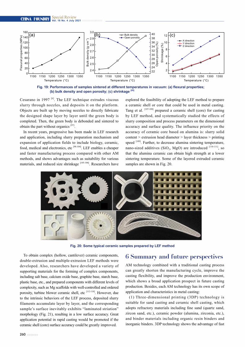
Li et al. [94] systematically studied the influence of sintering process on silica and alumina cores prepared via SL method. As sintering temperature increased to 1,300 °C, the silica-based ceramic cores reached a maximum value of 12.1 MPa due to the enhanced α-cristobalite content responsible for the flexural strength at room temperature. Vacuum sintering was introduced to improve the mechanical properties of alumina ceramic cores, as shown in Fig. 19. As the sintering temperature increased, the flexural strength and the hardness increased. Overall, 1,150 °C was determined to be the best sintering temperature in vacuum, yielding a ceramic core with bulk density of 2.43 g·cm-3, open porosity of 37.9%, and flexural strength of 33.7 MP, which was similar to results found from sintering at 1,280 °C in air. When the sintering temperature reaches 1,350 °C, the maximum shrinkage of the sample was close to 12% [95].
SL technique facilitates fabricating specimens with fine resolution and complicated structures, and it can be well combined with investment casting to replace a wax pattern, which then shortens traditional investment casting period. The dimensional accuracy of the castings based on SL investment patterns is up to CT4, and the surface roughness is less than 6.3 μm. However, this is still an indirect forming method; the surface of an investment pattern needs to be dip-coated multiple times to obtain the ceramic shell after drying, dewaxing and roasting. The size shrinkage of ceramic shell is large and difficult to control, which tends to generate deformation or cracking. Besides, the SL equipment operation and maintenance cost are high, and the liquid resin has odor and toxicity.
5 Layered extrusion forming (LEF)Layered extrusion forming, also known as direct ink writing (DIW) or robocasting (RC), was first filed as a patent by
260
CHINA FOUNDRY Vol. 18 No. 4 July 2021Special Review
Fig. 19: Performances of samples sintered at different temperatures in vacuum: (a) flexural properties; (b) bulk density and open porosity; (c) shrinkage [95]
Cesarano in 1997 [6]. The LEF technique extrudes viscous slurry through nozzles, and deposits it on the platform. Objects are built up by moving nozzles to directly fabricate the designed shape layer by layer until the green body is completed. Then, the green body is debonded and sintered to obtain the part without organics [97].
In recent years, progressive has been made in LEF research and application, including slurry preparation mechanism and expansion of application fields to include biology, ceramic, food, medical and electronics, etc [98-104]. LEF enables a cheaper and faster manufacturing process compared with other AM methods, and shows advantages such as suitability for various materials, and reduced size shrinkage [105-106]. Researchers have
explored the feasibility of adopting the LEF method to prepare a ceramic shell or core that could be used in metal casting. Tang et al. [107-108] prepared a ceramic shell (core) for casting by LEF method, and systematically studied the effects of slurry composition and process parameters on the dimensional accuracy and surface quality. The influence priority on the accuracy of ceramic core based on alumina is: slurry solid content > extrusion head diameter > layer thickness > printing speed [109]. Further, to decrease alumina sintering temperature, nano-sized additives (SiO2, MgO) are introduced [110-111], so that the alumina ceramic can obtain high strength at a lower sintering temperature. Some of the layered extruded ceramic samples are shown in Fig. 20.
160
140
120
100
80
60
40
20
0
Flex
ural
pro
pert
ies
(MP
a)
Temperature (°C)1100 1150 1200 1250 1300 1350
3.0
2.9
2.8
2.7
2.6
2.5
2.4
Bul
kde
nsity
(g·c
m)
-3
Temperature (°C)1100 1150 1200 1250 1300 1350
40383634323028262422
Ope
n po
rosi
ty(%
)
Bulk densitypen porosityO
12
10
8
6
4
2
Shr
inka
ge (%
)
Temperature (°C)1100 1150 1200 1250 1300 1350
X directionY directionZ direction
(a) (b) (c)
Fig. 20: Some typical ceramic samples prepared by LEF method
To obtain complex (hollow, cantilever) ceramic components, double-extrusion and multiple-extrusion LEF methods were developed. Also, researchers have developed a variety of supporting materials for the forming of complex components, including salt base, calcium oxide base, graphite base, starch base, plastic base, etc., and prepared components with different levels of complexity, such as Mg scaffolds with well-controlled and ordered porosity, turbine blower ceramic shell, etc [112-118]. However, due to the intrinsic behaviors of the LEF process, deposited slurry filaments accumulate layer by layer, and the corresponding sample’s surface inevitably exhibits “laminated striation” morphology (Fig. 21), resulting in a low surface accuracy. Great application potential in rapid casting would be promoted if the ceramic shell (core) surface accuracy could be greatly improved.
6 Summary and future perspectivesAM technology combined with a traditional casting process can greatly shorten the manufacturing cycle, improve the casting flexibility, and improve the production environment, which shows a broad application prospect in future casting production. Besides, each AM technology has its own scope of application and characteristics in metal casting:
(1) Three-dimensional printing (3DP) technology is suitable for sand casting and ceramic shell casting, which adopts refractory materials including fine sand (quartz sand, zircon sand, etc.), ceramic powder (alumina, zirconia, etc.), and binder materials including organic resin binders and inorganic binders. 3DP technology shows the advantage of fast

261
CHINA FOUNDRYVol. 18 No. 4 July 2021Special Review
formation, however, surface finishing post-treatment is required for fine precision casting.
(2) Selective laser sintering (SLS) is suitable for shell casting and investment casting, which adopts coated sands, wax-based materials and polymers to prepare a coated sand shell (core) and investment patterns. SLS technology has drawbacks, including high cost of material and device maintenance, and low strength of green parts. Besides, post heating curing is required for SLS prepared coated sand shell (core) to conduct metal casting. Investment patterns prepared by SLS need to be treated with dip-coating to improve strength and surface quality, after which procedures including coating, crusting, investment pattern removal and sintering are conducted to to generate a ceramic shell suitable for metal casting.
(3) Stereolithography (SL) can prepare an investment pattern and ceramic shell (core), adopting materials including photosensitive resin, and ceramic powder mixed with photosensitive resin. However, the cost of photosensitive resin and apparatus is relatively high. The investment patterns prepared by SL technique possess good surface quality and dimensional accuracy, but this method is still an indirect forming method for investment casting. Besides, ceramic shell (core) prepared by SL technique shows great size-shrinkage and poor dimensional stability after high temperature sintering due to high resin content, which brings cracks, deformation, and difficulty in controlling the accuracy of the ceramic shell (core).
(4) Layered extrusion forming (LEF) can prepare ceramic shells (cores) using slurries containing ceramic powders and liquid binder as starting materials. The method shows advantages of reduced cost of materials and apparatus, environmental-friendliness, and low dimensional shrinkage after sintering because of high solid content. At present, the surface roughness of a ceramic shell (core) prepared by LEF method requires further improvement, and some endeavors are required to satisfy requirements of investment casting surface accuracy.
Looking into the future, research on AM technology in the field of casting should give full play to the respective advantages of AM and casting processes, including process method, equipment accuracy, material types, etc. The key is to improve the precision of the shell (core) and reduce the preparation cost to realize intelligent, green, and high-quality development. The following lists some of the needed improvements:
(1) Mechanism that affects the molding accuracy, surface accuracy and strength performance of the casting mold (core) prepared by AM methods should be systematically studied. The formability of various materials and the defects formation mechanism of the mold (core) should be deeply studied to propose solutions to enhance accuracy and strength.
(2) Further improvement of sand shell (core) accuracy, and development of high-strength inorganic binders to meet the requirements of green casting is required for the 3DP method. Besides, efforts to improve core technology such as 3DP nozzles should be made.
(3) Issues of poor precision, deformation and cracking should be solved in direct preparation of the ceramic shell (core) through AM methods to realize the high efficiency and low-cost preparation. As the dimensional accuracy and surface quality of the prepared ceramic shell (core) can meet the requirements of investment casting, the traditional investment casting process will be completely reformed, and the production cycle of precision casting will be greatly shortened, which has great theoretical and practical significance.
AcknowledgementsThis work was financially supported by the National Natural Science Foundation of China (Grant Nos. 59635040, 51775204, 51375190) and the National Key R&D Program of China (Grant Nos. 2020YFB2008300, 2020YFB2008304).
References[1] Abdulhameed O, Al-Ahmari A, Ameen W, et al. Additive
manufacturing: Challenges, trends, and applications. Advances in Mechanical Engineering, 2019, 11(2): 2072051376.
[2] Hull C W. Apparatus for production of three-dimensional objects by stereo-lithography. US Patent No. US5556590 A, 1996.
[3] Deckard C R. Method and apparatus for producing parts by selective sintering. European Patent No. EP0287657, 1989.
[4] Sachs E M, Haggerty J S, Cima M J, et al. Three-dimensional pr int ing techniques. US Patent No. US5204055 A, 1993.
[5] Crump S S. Apparatus and method for creating three-dimensional objects, European Patent No. EP0426363, 1992.
[6] Cesarano III J, Calvert P D. Freeforming objects with low-binder slurry. US Patent No. US6027326, 2000.
Fig. 21: Layer-by-layer stacking diagram in LEF method: (a) extrusion diagram; (b) morphology of green sample; (c) surface roughness of sample [109]
(a)
(b) (c)

262
CHINA FOUNDRY Vol. 18 No. 4 July 2021Special Review
[7] Sivarupan T, Balasubramani N, Saxena P, et al. A review on the progress and challenges of binder jet 3D printing of sand moulds for advanced casting. Additive Manufacturing, 2021, 40: 101889.
[8] Lu B. Additive manufacturing-current situation and future. China Mechanical Engineering, 2020, 31(1): 19-23. (In Chinese)
[9] Fan Z T. Basic research on materials and processes in rapid prototyping of metal parts. Doctoral Dissertation, Huazhong University of Science and Technology, Wuhan, 1999. (In Chinese)
[10] Huang S, Zhang X, Ma L, et al. Development of rapid prototyping manufacturing technology. China Mechanical Engineering, 1997, 8(5): 8-12. (In Chinese)
[11] Kocel. Company Introduction. https://www.kocel.com/page3, July 2021.
[12] Singh S, Ramakrishna S, Singh R. Material issues in additive manufacturing: A review. Journal of Manufacturing Processes, 2017, 25: 185-200.
[13] Frazier W E. Metal additive manufacturing: A review. Journal of Materials Engineering and Performance, 2014, 23(6): 1917-1928.
[14] Chen Z W, Li Z Y, Li J J, et al. 3D printing of ceramics: A review. Journal of the European Ceramic Society, 2019, 39(4): 661-687.
[15] Dong Y J, Li Z M. Application and prospect of 3D printing and additive manufacturing technology in casting forming. Foundry Technology, 2018, 39(12): 2901-2904. (In Chinese)
[16] Duan W C, Gao J J , Dong B B, et al. Status and prospect of the 3D Printing technique in the field of metal casting. Foundry Technology, 2018, 39(12): 2895-2900. (In Chinese)
[17] Fan Z T, Huang N Y, Luo J R, et al. Evaluation of the methods to produce metal parts by RPM. China Mechanical Engineering, 1997, 8(5): 25-26, 55. (In Chinese)
[18] Feng T, Sun J, Zong G. Rapid and precision casting realized by selective laser sintering. China Mechanical Engineering, 1997, 8(5): 21-23, 116-117. (In Chinese)
[19] Fan Z, Huang N, Li Y, et al. Investigating on casting molds making with the coated sand by the selected laser sintering. In: Proc. International Conference on Rapid Prototyping & Manufacturing, Beijing China, 1998: 412-418.
[20] Guan Y, Wang F. Development and application of additive manufacturing (3D printing) casting. Technology Innovation and Application, 2020, 21: 110-111. (In Chinese)
[21] Li S H, Li Z Q. 3D printing and its application in rapidly casting technique. Foundry Technology, 2018, 39(2): 384-389. (In Chinese)
[22] FHZL. Sand 3D printer. http://www.fhzl.co/en/product2-743-2138.html, July 2021.
[23] EASYMFG. Product center. http://www.easy3dmade.com/list/7.html, July 2021.
[24] Lv X Y, Ye F, Cheng L F, et al. Binder jetting of ceramics: Powders, binders, printing parameters, equipment, and post-treatment. Ceramics International, 2019, 45(10): 12609-12624.
[25] Utela B, Storti D, Anderson R, et al. A review of process development steps for new material systems in three dimensional printing (3DP). Journal of Manufacturing Processes, 2008, 10(2): 96-104.
[26] Upadhyay M, Sivarupan T, El Mansori M. 3D printing for rapid sand casting-A review. Journal of Manufacturing Processes, 2017, 29: 211-220.
[27] Zocca A, Colombo P, Gomes C M, et al. Additive manufacturing of ceramics: Issues, potentialities, and opportunities. Journal of the American Ceramic Society, 2015, 98(7): 1983-2001.
[28] Ramakrishnan R, Griebel B, Volk W, et al. 3D printing of inorganic sand moulds for casting applications. Advanced Materials Research, 2014, 1018: 441-449.
[29] Hawaldar N, Zhang J. A comparative study of fabrication of sand casting mold using additive manufacturing and conventional process. International Journal of Advanced Manufacturing Technology, 2018, 97(1): 1037-1045.
[30] Snelling D A, Williams C B, Druschitz A P. Mechanical and material properties of castings produced via 3D printed molds. Additive Manufacturing, 2019, 27: 199-207.
[31] ExOne. Sand casting 3D printing materials & binders. 2020, https: //www.exone.com/en-US/3d-printing-materials-and-binders.
[32] Mi t ra S, Castro A R De, Mansor i M El . On the rapid manufacturing process of functional 3D printed sand molds. Journal of Manufacturing Processes, 2019, 42: 202-212.
[33] Zhao H P. Study on the key technology of rapid forming casting molds and cores by micro-jetting and bonding. Doctoral Dissertation, Huazhong University of Science and Technology, Wuhan, 2015. (In Chinese)
[34] Deng C Y, Kang J W, Shangguan H L, et al. Insulation effect of air cavity in sand mold using 3D printing technology. China Foundry, 2018, 15(1): 37-43.
[35] Tian L. Study on the materials and process of forming casting molds and cores by three-dimensional printing. Master Dissertation, Wuhan: Huazhong University of Science and Technology, 2017. (In Chinese)
[36] Li H. Optimization of pattern-less casting manufacturing based on addit ive manufactur ing technology. Master Dissertation, Taiyuan University of Technology, Taiyuan, 2016. (In Chinese)
[37] Sachs E M, Cima M J, Cornie J. Three-dimensional printing: rapid tooling and prototypes directly from a CAD model. CIRP Annals-Manufacturing Technology, 1990, 39(1): 201-204.
[38] Yan Y N, Li S J, Zhang R J, et al. Rapid prototyping and manufacturing technology: principle, representative technics, applications, and development trends. Tsinghua Science & Technology, 2009, 14(1): 1-12.
[39] Gil l S S, Kaplas M. Comparative study of 3D print ing technologies for rapid casting of aluminium alloy. Materials and Manufacturing Processes, 2009, 24: 1405-1411.
[40] Gill S S, Kaplas M. Efficacy of powder-based three-dimensional printing (3DP) technologies for rapid casting of light alloys. International Journal of Advanced Manufacturing Technology, 2011, 52: 53-64.
[41] Kaplas M, Singh R. Experimental investigations for reducing wall thickness in zinc shell casting using three-dimensional printing. Journal of Mechanical Engineering Science, 2008, 222(12): 2427-2431.
[42] Singh J P, Singh R. Investigations for a statistically controlled rapid casting solution of lead alloys using three-dimensional printing. Journal of Mechanical Engineering Science, 2009, 223(9): 2125-2134.
[43] Chhabra M, Singh R. Mathematical modeling of surface roughness of castings produced using ZCast direct metal casting. Journal of the Institution of Engineers, 2015, 96(2): 145-155.
[44] Zhao H P, Ye C C, Fan Z T, et al. 3D printing of CaO-based ceramic core using nanozirconia suspension as a binder. Journal of the European Ceramic Society, 2017, 37(15): 5119-5125.
[45] Zhao H P, Ye C C, Xiong S H, et al. Fabricating an effective calcium zirconate layer over the calcia grains via binder-jet 3D-printing for improving the properties of calcia ceramic cores. Additive Manufacturing, 2020, 32: 101025.
[46] Huang S J, Ye C S, Zhao H P, et al. Additive manufacturing of thin alumina ceramic cores using binder-jetting. Additive Manufacturing, 2019, 29: 100802.

263
CHINA FOUNDRYVol. 18 No. 4 July 2021Special Review
[47] Awad A, Fina F, Goyanes A, et al. 3D printing: Principles and pharmaceutical applications of selective laser sintering. International Journal of Pharmaceutics, 2020, 586: 119594.
[48] 3D Systems. Se lec t laser s in ter ing pr in ters . h t tp : / /www.3dsystems-china.com/printers/#p95, August 2021.
[49] EOS. EOS polymer systems. https://www.eos-apac.info/info2.php?class_id=110101101102&id=465, July 2021.
[50] Longyuan AFS. Selective laser sintering rapid molding machine - Product center. http://www.lyafs.com.cn/products.aspx?id=4, July 2021.
[51] Huake 3D Technology Product Center. http://www.huake3d.com/product_detail.asp?Product_ID=45&Product_ParentID=6, July 2021.
[52] Farsoon Technologies. Farsoon total solutions for polymer additive manufacturing. http://en.farsoon.com/solution_list_01.html, July 2021.
[53] Xu Z F, Liang P, Yang W, et al. Effects of laser energy density on forming accuracy and tensile strength of selective laser sintering resin coated sands. China foundry, 2014, 11(3): 151-156.
[54] Fan Z, Huang N, Yan L, et al. Investigating on casting mold (or core) making with coated sand by the selected laser sintering. China Foundry, 2004, 1(2): 122-126.
[55] Fan Z T, Huang N Y, Xiao Y J. Accuracy analysis of the part made by selected laser sintering. China Foundry, 2004, 1(1): 49-52.
[56] Fan Z T, Huang N Y, Song X J, et al. The measures of improving the sintered strength of the coated sand mold (or core) made by selected laser sintering (SLS). Special Casting & Nonferrous Alloys, 1999(2): 1-4. (In Chinese)
[57] Fan Z T, Huang N Y, Chen Z M, et al. Quick casting by selective laser sintering (SLS). Special Casting & Nonferrous Alloys, 1999(5): 7-9. (In Chinese)
[58] Wen S F, Shen Q W, Wei Q S, et al. Material optimization and post-processing of sand moulds manufactured by the selective laser sintering of binder-coated Al2O3 sands. Journal of Materials Processing Technology, 2015, 225: 93-102.
[59] Tang Y, Fuh J Y H, Loh H T, et al. Direct laser sintering of a silica sand. Materials and Design, 2003, 24: 623-629.
[60] Bo F X, He B, Zong X M. Selective laser sintering process of coated sands. Laser & Optoelectronics Progress, 2017, 54(9): 247-253. (In Chinese)
[61] Wang C, Shen Q, Pang Z. SLS quickly manufactures vermicular graphite cast iron cylinder heads for large complex four-valve six-cylinder diesel engines. In: Proc. 2010 China Foundry Congress, Hangzhou: 2010. (In Chinese)
[62] Si C, Dang J Z, Li Y X, et al. Study on preparation process of precoated sand for laser 3D printing. Hot Working Technology, 2018, 47(5): 93-95. (In Chinese)
[63] Si C. Study on the preparation and molding process of coated sand for laser 3D printing. Master Dissertation, North University of China, Taiyuan, 2018. (In Chinese)
[64] Liang X W, Wang D P, Xu Z F, et al. Preparation of coated zircon sand used for selective laser sintering and study on the forming process of SLS. Foundry, 2017, 66(8): 814-819. (In Chinese)
[65] Li C H, Hu L, Zou Y, et al. Fabrication of Al2O3-SiO2 ceramics through combined selective laser sintering and SiO2-sol infiltration. International Journal of Applied Ceramic Technology, 2019, 17(1): 255-263.
[66] Wei Q, Zhong J W, Xu Z L, et al. Microstructure evolution and mechanical properties of ceramic shell moulds for investment casting of turbine blades by selective laser sintering. Ceramics International, 2018, 44(11): 12088-12097.
[67] Wei Q, Xu Z, Xu Q, et al. Effect of sintering temperature on microstructure and mechanical behavior of alumina-based ceramic shell by SLS. Journal of Aeronautical Materials, 2019, 39(2): 10-15.
[68] Zhao X. Preparation and application of ceramic core. Beijing: Science Press, 2013. (In Chinese)
[69] Kanyo J E, Schafföner S, Uwanyuze R S, et al. An overview of ceramic molds for investment casting of nickel superalloys. Journal of the European Ceramic Society, 2020, 40(15): 4955 4973.
[70] Tang Y, Deng Q, Zhang H. Selective laser sintering molding technology and its application in precision casting of aerospace parts. Aviation Precision Manufacturing Technology, 1996(2): 21-24.
[71] Yan C, Shi Y, Wei Q, et al. Laser selective sintering 3D printing technology. Wuhan: Huazhong University of Science and Technology Press, 2019.
[72] Shi Y S, Chen J B, Wang Y, et al. Study of the selective laser sintering of polycarbonate and postprocess for parts reinforcement. Journal of Materials Design & Applications, 2006, 221(1): 37-42.
[73] Shi Y S, Wang Y, Chen J B, et al. Experimental investigation into the selective laser sintering of high-impact polystyrene. Journal of Applied Polymer Science, 2008, 108(1): 535-540.
[74] Yang J S, Shi Y S, Shen Q W, et al. Selective laser sintering of HIPS and investment casting technology. Journal of Materials Processing Technology, 2009, 209(4): 1901-1908.
[75] Özer G, özbay B, öter Z Ç, et al. Investigation of the surface quality and dimensional accuracy of polymer patterns produced by selective laser sintering (SLS) method for investment casting (IC). International Journal of Cast Metals Research, 2020, 33(2-3): 146-152.
[76] Wang D H, Dong A P, Zhu G L, et al. Rapid casting of complex impeller based on 3D printing wax pattern and simulation optimization. International Journal of Advanced Manufacturing Technology, 2019, 100(9-12): 2629-2635.
[77] Yang L X, Bai X, Xu C, et al. Investment casting process of induction wheel based on SLS. Foundry, 2019, 68(10): 1121-1126. (In Chinese)
[78] Li S S, Xu Z F, Zhao Y Y, et al. Flame retardant mechanism analysis of magnesium alloy for selective laser sintering coated sand mold (core) casting. Foundry, 2015, 64(2): 140-143. (In Chinese)
[79] Sun X, Luo Z W, Zhang J Q. Application of SLS technology in investment casting. China Plastics Industry, 2019, 47(11): 68-70. (In Chinese)
[80] Hu K H, Zhao P C, Lu Z G. Application of stereolithography technology to investment casting. Foundry, 2021, 70(2): 155-159. (In Chinese)
[81] Zakeri S, Vippola M, Levänen E. A comprehensive review of the photopolymerizat ion of ceramic resins used in stereolithography. Additive Manufacturing, 2020(35): 101177.
[82] 3D Systems. Stereolithography https://cn.3dsystems.com/resources/information-guides/stereolithography/sla, July 2021.
[83] Zong X, Liu J, Xu W. Rapid investment-low pressure casting of complicated based on SLA. Special Casting & Nonferrous Alloys, 2019, 39(3): 300-303. (In Chinese)
[84] Li D, Lu Z, Jing H. A method for customizing the core and shell of a hollow turbine blade integrated ceramic mold. China Patent, ZL201310289486.0. (In Chinese)
[85] Chen X, Li D, Wu H, et al. Analysis of ceramic shell cracking in stereolithography-based rapid casting of turbine blade. International Journal of Advanced Manufacturing Technology, 2011, 55(5-8): 447-455.
[86] Wu H, Li D, Tang Y, et al. Rapid fabrication of alumina-based ceramic cores for gas turbine blades by stereolithography and gelcasting. Journal of Materials Processing Technology, 2009, 209(18-19): 5886-5891.
[87] Yang Q, Zhu W, Lu Z, et al. Rapid fabrication of high-performance CaO-based integral ceramic mould by stereolithography and non-aqueous gelcasting. Materials, 2019, 12(6): 934.

264
CHINA FOUNDRY Vol. 18 No. 4 July 2021Special Review
[88] Li H, Liu Y, Liu Y, et al. Effect of sintering temperature in argon atmosphere on microstructure and properties of 3D printed alumina ceramic cores. Journal of Advanced Ceramics, 2020, 9(2): 220-231.
[89] Bae C, Kim D, Halloran J W. Mechanical and kinetic studies on the refractory fused silica of integrally cored ceramic mold fabricated by additive manufacturing. Journal of the European Ceramic Society, 2019, 39(2-3): 618-623.
[90] Bae C, Halloran J W. Integral ly cored ceramic mold fabricated by ceramic stereolithography. International Journal of Applied Ceramic Technology, 2011, 8(6): 1255-1262
[91] H a l l o r a n J W, To m e c k o v a V, G e n t r y S , e t a l . Photopolymerization of powder suspensions for shaping ceramics. Journal of the European Ceramic Society, 2011, 31(14): 2613-2619.
[92] Hal loran J W. Ceramic stereol i thography: addi t ive manufacturing for ceramics by photopolymerization. Annual Review of Materials Research, 2016, 46(1): 19-40.
[93] Li F, Ji X, Wu Z, et al. Digital light processing 3D printing of ceramic shell for precision casting. Materials Letters, 2020, 276: 128037.
[94] Li H, Hu K, Liu Y, et al. Improved mechanical properties of silica ceramic cores prepared by 3D printing and sintering processes. Scripta Material, 2021, 194: 113665.
[95] Li H, Liu Y, Liu Y, et al. Evolution of the microstructure and mechanical properties of stereolithography formed alumina cores sintered in vacuum. Journal of the European Ceramic Society, 2020, 40: 4825-4836.
[96] Jiang Y, He C, Shao Z. Rapid casting of enclosed impeller based on ProCAST and 3D printing technology. Journal of Mechanical & Electrical Engineering, 2015, 32(9): 1166-1169+1191.
[97] Li Y Y. Research on the freeform direct writing technique based on ceramic ink. Doctoral Dissertation, Tsinghua University, Beijing, 2015. (In Chinese)
[98] Zocca A, Franchin G, Elsayed H, et al. Direct ink writing of a preceramic polymer and fillers to produce hardystonite (Ca2ZnSi2O7) bioceramic scaffolds. Journal of the American Ceramic Society, 2016, 99(6): 1960-1967.
[99] Koski C, Onuike B, Bandyopadhyay A, et al. Starch-hydroxyapatite composite bone scaffold fabrication utilizing a slurry extrusion-based solid freeform fabricator. Additive Manufacturing, 2018, 24: 47-59.
[100] Kenel C, Casati N P M, Dunand D C. 3D ink-extrusion additive manufacturing of CoCrFeNi high-entropy alloy micro-lattices. Nature Communications, 2019, 10(1): 904.
[101] Martínez-Vázquez F J, Perera F H, Miranda P, et al. Improving the compressive strength of bioceramic robocast scaffolds by polymer infiltration. Acta Biomaterialia, 2010, 6(11): 4361-4368.
[102] Rowlands W, Vaidhyanathan B. Additive manufacturing of barium titanate based ceramic heaters with positive temperature coefficient of resistance (PTCR). Journal of the European Ceramic Society, 2019, 39(12): 3475-3483.
[103] Zhu W J. Research on the development of high viscosity material 3D printer and its application in food and medicine printing. Master Dissertation, Zhejiang University, Hanghzou, 2015. (In Chinese)
[104] Zhang D, Chi B, Li B, et al. Fabrication of highly conductive graphene flexible circuits by 3D printing. Synthetic Metals, 2016, 217: 79-86.
[105] Hon K K B, Li L, Hutchings I M. Direct writing technology- Advances and developments. CIRP Annals, 2008, 57(2): 601-620.
[106] Lewis J A, Smay J E, Stuecker J, et al. Direct ink writing of three-dimensional ceramic structures. Journal of the American Ceramic Society, 2006, 89(12): 3599-3609.
[107] Tang S, Fan Z, Zhao H, et al. Layered extrusion forming-a simple and green method for additive manufacturing ceramic core. International Journal of Advanced Manufacturing Technology, 2018, 96(9-12): 3809-3819.
[108] Yang L, Tang S, Li G, et al. Performance characteristics of collapsible CaO-SiO2 based ceramic core material via layered extrusion forming. Ceramics International, 2019, 45(6): 7681–7689.
[109] Tang S, Yang L, Li G, et al. 3D printing of highly-loaded slurries via layered extrusion forming: Parameters optimization and control. Additive Manufacturing, 2019, 28(6): 546-553.
[110] Tang S, Yang L, Liu X, et al. Direct ink writing additive manufacturing of porous alumina-based ceramic cores modified with nanosized MgO. Journal of the European Ceramic Society, 2020, 40(15): 5758-5766.
[111] Tang S, Yang L, Li G, et al. Effect of the addition of silica sol on layered extrusion forming of Al2O3-based cores. Advances in Applied Ceramics, 2019, 118(3): 145-152.
[112] Yang L, Tang S, Li G, et al. Layered extrusion forming of complex ceramic structures using starch as removable support. Ceramics International, 2019, 45(17): 21843-21850.
[113] Li G, Tang S, Yang L, et al. Fabrication of soluble salt-based support for suspended ceramic structure by layered extrusion forming method. Materials & Design, 2019, 183: 108173.
[114] Kleger N, Cihova M, Masania K, et al. 3D Printing of salt as a template for magnesium with structured porosity. Advanced Materials, 2019, 31(37): 1903783.
[115] Li W, Ghazanfari A, McMillen D, et al. Fabricating ceramic components with water dissolvable support structures by the ceramic on-demand extrusion process. CIRP Annals, 2017, 66(1): 225-228.
[116] Martínez-Vázquez F J, Pajares A, Miranda P. A simple graphite-based support material for robocasting of ceramic parts. Journal of the European Ceramic Society, 2018, 38(4): 2247-2250.
[117] Xu C, Quinn B, Lebel L L, et al. Multi-material direct ink writing (DIW) for complex 3D metallic structures with removable supports. ACS Applied Materials & Interfaces, 2019, 11(8): 8499-8506.
[118] Li W, Armani A, Mcmillen D, et al. Additive manufacturing of zirconia parts with organic sacrificial supports. International Journal of Applied Ceramic Technology, 2020, 17(4): 1544-1553.