Development of Additive Manufacturing Technology … · Development of Additive Manufacturing...
8
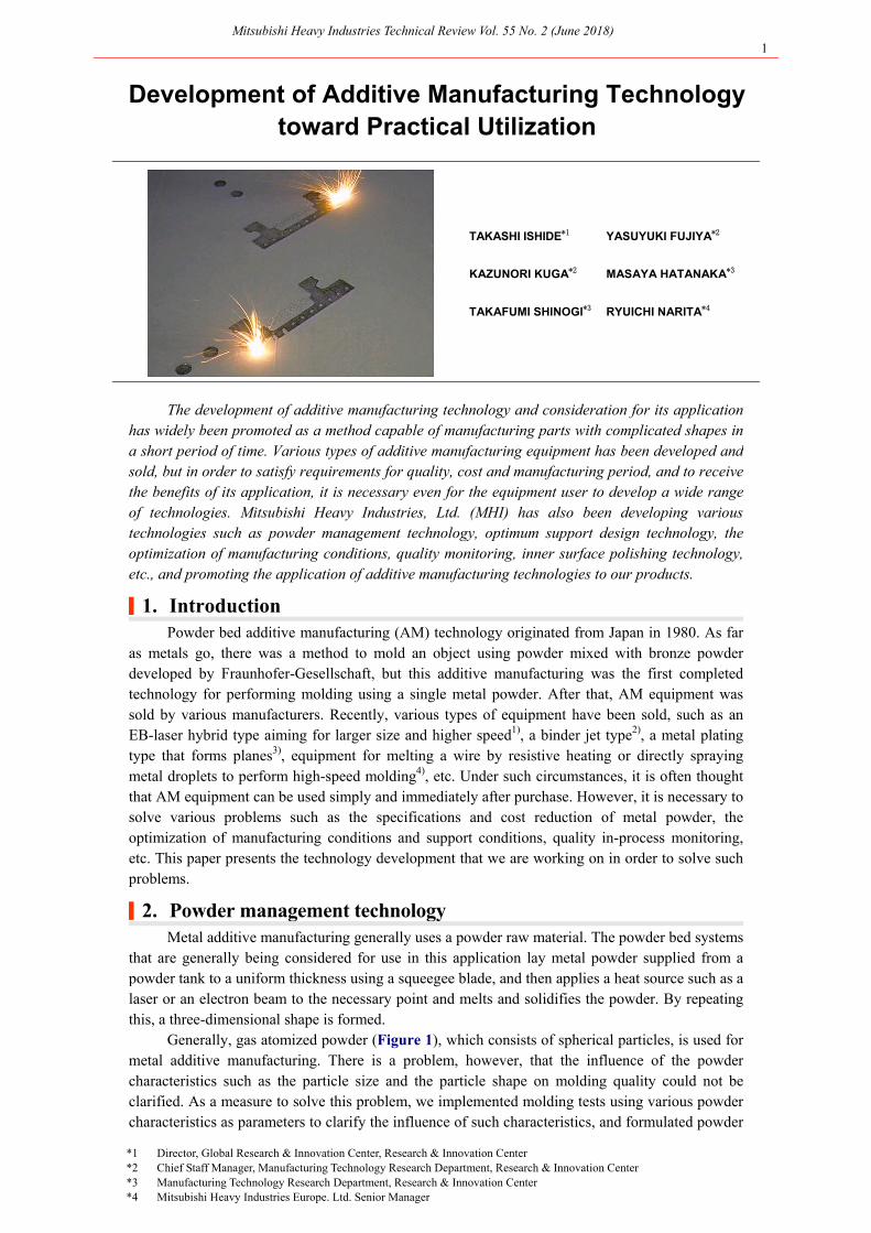
Mitsubishi Heavy Industries Technical Review Vol. 55 No. 2 (June 2018) 1 *1 Director, Global Research & Innovation Center, Research & Innovation Center *2 Chief Staff Manager, Manufacturing Technology Research Department, Research & Innovation Center *3 Manufacturing Technology Research Department, Research & Innovation Center *4 Mitsubishi Heavy Industries Europe. Ltd. Senior Manager Development of Additive Manufacturing Technology toward Practical Utilization TAKASHI ISHIDE *1 YASUYUKI FUJIYA *2 KAZUNORI KUGA *2 MASAYA HATANAKA *3 TAKAFUMI SHINOGI *3 RYUICHI NARITA *4 The development of additive manufacturing technology and consideration for its application has widely been promoted as a method capable of manufacturing parts with complicated shapes in a short period of time. Various types of additive manufacturing equipment has been developed and sold, but in order to satisfy requirements for quality, cost and manufacturing period, and to receive the benefits of its application, it is necessary even for the equipment user to develop a wide range of technologies. Mitsubishi Heavy Industries, Ltd. (MHI) has also been developing various technologies such as powder management technology, optimum support design technology, the optimization of manufacturing conditions, quality monitoring, inner surface polishing technology, etc., and promoting the application of additive manufacturing technologies to our products. | 1. Introduction Powder bed additive manufacturing (AM) technology originated from Japan in 1980. As far as metals go, there was a method to mold an object using powder mixed with bronze powder developed by Fraunhofer-Gesellschaft, but this additive manufacturing was the first completed technology for performing molding using a single metal powder. After that, AM equipment was sold by various manufacturers. Recently, various types of equipment have been sold, such as an EB-laser hybrid type aiming for larger size and higher speed 1) , a binder jet type 2) , a metal plating type that forms planes 3) , equipment for melting a wire by resistive heating or directly spraying metal droplets to perform high-speed molding 4) , etc. Under such circumstances, it is often thought that AM equipment can be used simply and immediately after purchase. However, it is necessary to solve various problems such as the specifications and cost reduction of metal powder, the optimization of manufacturing conditions and support conditions, quality in-process monitoring, etc. This paper presents the technology development that we are working on in order to solve such problems. | 2. Powder management technology Metal additive manufacturing generally uses a powder raw material. The powder bed systems that are generally being considered for use in this application lay metal powder supplied from a powder tank to a uniform thickness using a squeegee blade, and then applies a heat source such as a laser or an electron beam to the necessary point and melts and solidifies the powder. By repeating this, a three-dimensional shape is formed. Generally, gas atomized powder (Figure 1), which consists of spherical particles, is used for metal additive manufacturing. There is a problem, however, that the influence of the powder characteristics such as the particle size and the particle shape on molding quality could not be clarified. As a measure to solve this problem, we implemented molding tests using various powder characteristics as parameters to clarify the influence of such characteristics, and formulated powder
Transcript of Development of Additive Manufacturing Technology … · Development of Additive Manufacturing...
Mitsubishi Heavy Industries Technical Review Vol. 55 No. 2 (June 2018) 1
*1 Director, Global Research & Innovation Center, Research & Innovation Center *2 Chief Staff Manager, Manufacturing Technology Research Department, Research & Innovation Center *3 Manufacturing Technology Research Department, Research & Innovation Center *4 Mitsubishi Heavy Industries Europe. Ltd. Senior Manager
Development of Additive Manufacturing Technology toward Practical Utilization
TAKASHI ISHIDE*1 YASUYUKI FUJIYA*2 KAZUNORI KUGA*2 MASAYA HATANAKA*3
TAKAFUMI SHINOGI*3 RYUICHI NARITA*4
The development of additive manufacturing technology and consideration for its application
has widely been promoted as a method capable of manufacturing parts with complicated shapes ina short period of time. Various types of additive manufacturing equipment has been developed andsold, but in order to satisfy requirements for quality, cost and manufacturing period, and to receivethe benefits of its application, it is necessary even for the equipment user to develop a wide range of technologies. Mitsubishi Heavy Industries, Ltd. (MHI) has also been developing varioustechnologies such as powder management technology, optimum support design technology, the optimization of manufacturing conditions, quality monitoring, inner surface polishing technology, etc., and promoting the application of additive manufacturing technologies to our products.
|1. Introduction Powder bed additive manufacturing (AM) technology originated from Japan in 1980. As far
as metals go, there was a method to mold an object using powder mixed with bronze powderdeveloped by Fraunhofer-Gesellschaft, but this additive manufacturing was the first completedtechnology for performing molding using a single metal powder. After that, AM equipment was sold by various manufacturers. Recently, various types of equipment have been sold, such as anEB-laser hybrid type aiming for larger size and higher speed1), a binder jet type2), a metal plating type that forms planes3), equipment for melting a wire by resistive heating or directly spraying metal droplets to perform high-speed molding4), etc. Under such circumstances, it is often thought that AM equipment can be used simply and immediately after purchase. However, it is necessary tosolve various problems such as the specifications and cost reduction of metal powder, theoptimization of manufacturing conditions and support conditions, quality in-process monitoring, etc. This paper presents the technology development that we are working on in order to solve such problems.
|2. Powder management technology Metal additive manufacturing generally uses a powder raw material. The powder bed systems
that are generally being considered for use in this application lay metal powder supplied from apowder tank to a uniform thickness using a squeegee blade, and then applies a heat source such as alaser or an electron beam to the necessary point and melts and solidifies the powder. By repeatingthis, a three-dimensional shape is formed.
Generally, gas atomized powder (Figure 1), which consists of spherical particles, is used for metal additive manufacturing. There is a problem, however, that the influence of the powdercharacteristics such as the particle size and the particle shape on molding quality could not beclarified. As a measure to solve this problem, we implemented molding tests using various powdercharacteristics as parameters to clarify the influence of such characteristics, and formulated powder
Mitsubishi Heavy Industries Technical Review Vol. 55 No. 2 (June 2018) 2
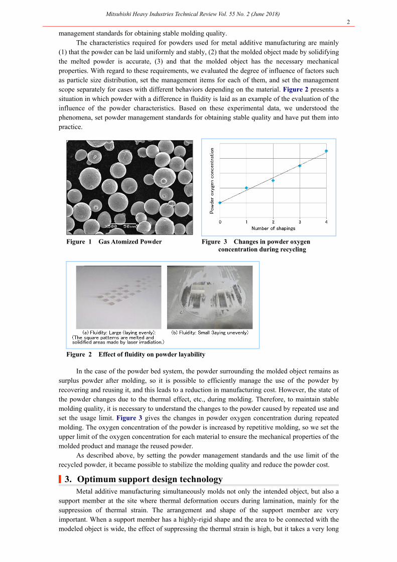
management standards for obtaining stable molding quality. The characteristics required for powders used for metal additive manufacturing are mainly
(1) that the powder can be laid uniformly and stably, (2) that the molded object made by solidifyingthe melted powder is accurate, (3) and that the molded object has the necessary mechanical properties. With regard to these requirements, we evaluated the degree of influence of factors suchas particle size distribution, set the management items for each of them, and set the managementscope separately for cases with different behaviors depending on the material. Figure 2 presents a situation in which powder with a difference in fluidity is laid as an example of the evaluation of theinfluence of the powder characteristics. Based on these experimental data, we understood the phenomena, set powder management standards for obtaining stable quality and have put them intopractice.
Figure 1 Gas Atomized Powder Figure 3 Changes in powder oxygen concentration during recycling
Figure 2 Effect of fluidity on powder layability
In the case of the powder bed system, the powder surrounding the molded object remains as surplus powder after molding, so it is possible to efficiently manage the use of the powder byrecovering and reusing it, and this leads to a reduction in manufacturing cost. However, the state ofthe powder changes due to the thermal effect, etc., during molding. Therefore, to maintain stable molding quality, it is necessary to understand the changes to the powder caused by repeated use andset the usage limit. Figure 3 gives the changes in powder oxygen concentration during repeatedmolding. The oxygen concentration of the powder is increased by repetitive molding, so we set theupper limit of the oxygen concentration for each material to ensure the mechanical properties of themolded product and manage the reused powder.
As described above, by setting the powder management standards and the use limit of therecycled powder, it became possible to stabilize the molding quality and reduce the powder cost.
|3. Optimum support design technology Metal additive manufacturing simultaneously molds not only the intended object, but also a
support member at the site where thermal deformation occurs during lamination, mainly for thesuppression of thermal strain. The arrangement and shape of the support member are veryimportant. When a support member has a highly-rigid shape and the area to be connected with the modeled object is wide, the effect of suppressing the thermal strain is high, but it takes a very long

Mitsubishi Heavy Industries Technical Review Vol. 55 No. 2 (June 2018) 3
time to remove the support member in post-processing. Meanwhile, if a support member is molded in a space inside the molded product which is difficult to access with a removal tool, it cannot beremoved in post-processing. For this reason, it is necessary to be able to form a support memberthat is small in quantity, has low rigidity and within the target shape tolerance while considering the workability in the process of removing the support member.
Therefore, we constructed an optimum support design system with the product posture as avariable. Figure 4 illustrates the process of this system. In order to make this system more practical, we evaluated the ease of tool access for support removal (Figure 5 (a)), rather than simply minimizing the support amount. In general, when the angle of the modeling surface withrespect to the orthogonal stacking direction exceeds a certain value, support is unnecessary (Figure5.2). For this reason, the determination of whether a support is necessary is a piecewisediscontinuous function with respect to the product posture (angle). The optimal solution searchalgorithm uses GA (genetic algorithm) to prevent falling into a local solution. However, since thenumber of calculations for GA is enormous, the calculation including modeling takes much time.Therefore, a response phase was created, and optimization analysis was performed. At this time, the accuracy of the response surface was confirmed by confirmation calculation and the optimalsolution was sought again after updating the response surface. As a result of repeating suchconfirmation, the prediction accuracy was improved and we could obtain a better solution.
Figure 6 presents the results of trial calculation targeting a certain mechanical component.By building an optimum support design system suitable for the characteristics of metal additivemanufacturing based on these results, a molding posture that minimizes the support amount can bederived while eliminating dependency on individual skill.
Figure 4 Optimum support design system process Figure 6 Trial calculation results
Figure 5 Evaluation of supportability and support necessity
Mitsubishi Heavy Industries Technical Review Vol. 55 No. 2 (June 2018) 4
|4. Process condition optimization technology The process conditions suggested by the equipment manufacturer are those for the material
supplied from the equipment manufacturer. Therefore, it is unknown whether the optimum process condition settings are set. In addition, when molding materials and shapes that have not beenmolded so far, it is necessary to ask the equipment manufacturer to consider the process conditions,so the selection of the optimum process conditions requires a long period of time and enormous cost, which leads to a bottleneck. Therefore, we standardized the condition selection flow to obtainthe appropriate process conditions for applying additive manufacturing to a new material.
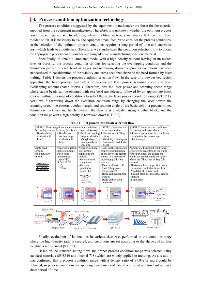
Specifically, to obtain a laminated model with a high density without leaving an un-melted layer or porosity, the process condition settings for selecting the overlapping condition and thelamination pattern of each bead in stages and narrowing down the process conditions has beenstandardized in consideration of the stability and cross-sectional shape of the bead formed by laser melting. Table 1 depicts the process condition selection flow. In the case of a powder bed fusionapparatus, the basic process parameters of process are laser power, scanning speed and bead overlapping amount (hatch interval). Therefore, first the laser power and scanning speed rangewhere stable beads can be obtained with one bead are selected, followed by an appropriate hatchinterval within the range of conditions to select the single layer process condition range (STEP 1).Next, while narrowing down the execution condition range by changing the laser power, thescanning speed, the pattern, overlap margin and rotation angle of the basic cell at a predetermined lamination thickness and hatch interval, the density is evaluated using a cubic block, and thecondition range with a high density is narrowed down (STEP 2).
Table 1 3D process condition selection flow
[STEP 1] Narrowing down the manufacturing conditions by one layer manufacturing (set for each layer thickness)
[STEP 2] Selecting the process condition
[STEP 3] Selecting the conditions according to the part shape
1. Bead stability evaluation (1 bead)
2. Bead cross section shape evaluation (1 bead)
3. Bead overlapping shape evaluation
(Single-layer multipass bead stacking)
4. Evaluation of filling factor
(Multilayer multipass laminated bead: Cube block)
5. Limit shape and surface condition evaluation (various-shape laminating)
Stable bead forming conditions are selected
Proper penetration shape conditions are selected - Penetration
depth (d0) 1.5t≦d0≦2t
Appropriate bead overlapping conditions are selected - Overlap bead
roughness - Overlap
penetration depth (d1)
Based on the lamination proper condition range of one layer, the proper pattern to homogenize modeling quality are selected - Pattern of basic cell
(unit filling area) (stripe, chess)
- Basic cell overlapping margin
- Basic cell rotation angle (θ)
Appropriate heat input conditions are selected according to the shape of the part under the conditions within the proper condition range where the filling rate of Step 2 is secured - Horizontal hole (upper limit with
no support, moldable lower limit) - Moldable slit lower limit - Lowest plate thickness that can be
molded - Limit angle
Finally, evaluation of laminations in various sizes was performed in the condition rangewhere the high-density ratio is secured, and conditions are set according to the shape and surfaceroughness requirement (STEP 3).
Based on the standard setting flow, the proper process condition range was selected using standard materials (SUS316 and Inconel 718) which are widely applied to molding. As a result, itwas confirmed that a process condition range with a density ratio of 99.9% or more could beobtained, so process conditions for applying a new material can be optimized at a low cost and in a short period of time.
Mitsubishi Heavy Industries Technical Review Vol. 55 No. 2 (June 2018) 5
|5. Quality monitoring technology Metal additive manufacturing takes several dozen hours for the completion of lamination
molding. However, currently there are no methods or criteria for stopping the molding when a failure occurs. Therefore, if the molded object fails the quality inspection after molding operation,significant rework will be required. As such, for the purpose of the prevention of rework andsecuring traceability, we developed a monitoring technology targeting the state of the powderlaying and the surface condition after laser irradiation as the molding situation.
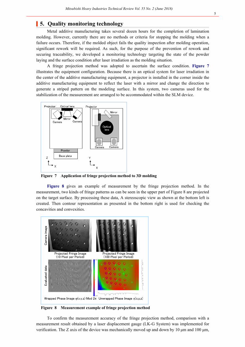
A fringe projection method was adopted to ascertain the surface condition. Figure 7illustrates the equipment configuration. Because there is an optical system for laser irradiation inthe center of the additive manufacturing equipment, a projector is installed in the corner inside theadditive manufacturing equipment to reflect the laser with a mirror and change the direction to generate a striped pattern on the modeling surface. In this system, two cameras used for thestabilization of the measurement are arranged to be accommodated within the SLM device.
Figure 7 Application of fringe projection method to 3D molding
Figure 8 gives an example of measurement by the fringe projection method. In themeasurement, two kinds of fringe patterns as can be seen in the upper part of Figure 8 are projected on the target surface. By processing these data, A stereoscopic view as shown at the bottom left iscreated. Then contour representation as presented in the bottom right is used for checking theconcavities and convexities.
Figure 8 Measurement example of fringe projection method
To confirm the measurement accuracy of the fringe projection method, comparison with ameasurement result obtained by a laser displacement gauge (LK-G System) was implemented for verification. The Z axis of the device was mechanically moved up and down by 10 μm and 100 μm,
Mitsubishi Heavy Industries Technical Review Vol. 55 No. 2 (June 2018) 6
and the height change of the modeling surface was measured by the two. As a result, it was verifiedthat the measurement of the fringe projection method was comparable to the measurement of the laser displacement gauge. Table 2 is a comparison of the measurement results of the 1 mm steppedflat plate obtained by the fringe projection method and by a three-dimensional measuring instrument. It was confirmed that the measurement of the fringe projection method was comparableto the measurement of the three-dimensional measuring instrument. Based on the above twoverification results, it was confirmed that the fringe projection method can implementhighly-precise measurement.
Table 2 Comparison of measurement results of fringe
projection method and three-dimensional measuring instrument
Measurement result Fringe projection 1.032 mm +/- 17.8 µm (1σ) Three-dimensional measuring instrument 1.037 mm +/- 9.7 µm (1σ)
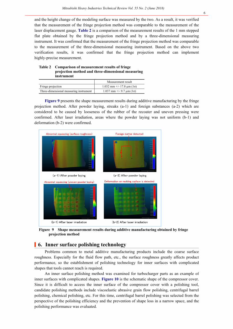
Figure 9 presents the shape measurement results during additive manufacturing by the fringe
projection method. After powder laying, streaks (a-1) and foreign substances (a-2) which are considered to be caused by looseness of the rubber of the recoater and uneven pressing wereconfirmed. After laser irradiation, areas where the powder laying was not uniform (b-1) and deformation (b-2) were confirmed.
Figure 9 Shape measurement results during additive manufacturing obtained by fringe projection method
|6. Inner surface polishing technology Problems common to metal additive manufacturing products include the coarse surface
roughness. Especially for the fluid flow path, etc., the surface roughness greatly affects productperformance, so the establishment of polishing technology for inner surfaces with complicatedshapes that tools cannot reach is required.
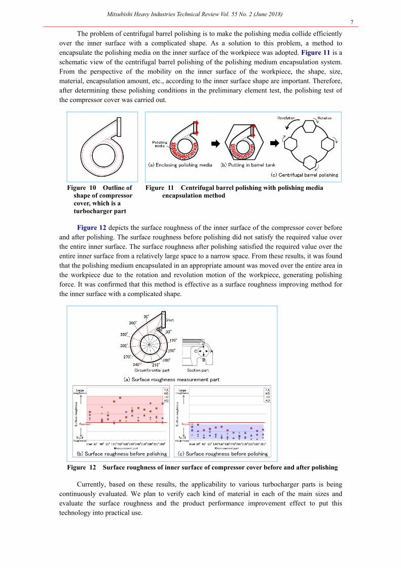
An inner surface polishing method was examined for turbocharger parts as an example of inner surfaces with complicated shapes. Figure 10 is the schematic shape of the compressor cover. Since it is difficult to access the inner surface of the compressor cover with a polishing tool,candidate polishing methods include viscoelastic abrasive grain flow polishing, centrifugal barrelpolishing, chemical polishing, etc. For this time, centrifugal barrel polishing was selected from theperspective of the polishing efficiency and the prevention of shape loss in a narrow space, and the polishing performance was evaluated.
Mitsubishi Heavy Industries Technical Review Vol. 55 No. 2 (June 2018) 7
The problem of centrifugal barrel polishing is to make the polishing media collide efficientlyover the inner surface with a complicated shape. As a solution to this problem, a method toencapsulate the polishing media on the inner surface of the workpiece was adopted. Figure 11 is a schematic view of the centrifugal barrel polishing of the polishing medium encapsulation system.From the perspective of the mobility on the inner surface of the workpiece, the shape, size, material, encapsulation amount, etc., according to the inner surface shape are important. Therefore,after determining these polishing conditions in the preliminary element test, the polishing test ofthe compressor cover was carried out.
Figure 10 Outline of shape of compressor cover, which is a turbocharger part
Figure 11 Centrifugal barrel polishing with polishing media encapsulation method
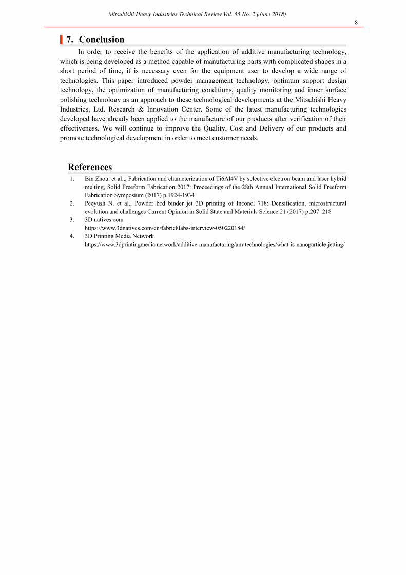
Figure 12 depicts the surface roughness of the inner surface of the compressor cover before
and after polishing. The surface roughness before polishing did not satisfy the required value overthe entire inner surface. The surface roughness after polishing satisfied the required value over the entire inner surface from a relatively large space to a narrow space. From these results, it was foundthat the polishing medium encapsulated in an appropriate amount was moved over the entire area inthe workpiece due to the rotation and revolution motion of the workpiece, generating polishingforce. It was confirmed that this method is effective as a surface roughness improving method forthe inner surface with a complicated shape.
Figure 12 Surface roughness of inner surface of compressor cover before and after polishing
Currently, based on these results, the applicability to various turbocharger parts is beingcontinuously evaluated. We plan to verify each kind of material in each of the main sizes andevaluate the surface roughness and the product performance improvement effect to put thistechnology into practical use.
Mitsubishi Heavy Industries Technical Review Vol. 55 No. 2 (June 2018) 8
|7. Conclusion In order to receive the benefits of the application of additive manufacturing technology,
which is being developed as a method capable of manufacturing parts with complicated shapes in ashort period of time, it is necessary even for the equipment user to develop a wide range oftechnologies. This paper introduced powder management technology, optimum support designtechnology, the optimization of manufacturing conditions, quality monitoring and inner surfacepolishing technology as an approach to these technological developments at the Mitsubishi HeavyIndustries, Ltd. Research & Innovation Center. Some of the latest manufacturing technologiesdeveloped have already been applied to the manufacture of our products after verification of theireffectiveness. We will continue to improve the Quality, Cost and Delivery of our products and promote technological development in order to meet customer needs.
References 1. Bin Zhou. et al.,, Fabrication and characterization of Ti6Al4V by selective electron beam and laser hybrid
melting, Solid Freeform Fabrication 2017: Proceedings of the 28th Annual International Solid FreeformFabrication Symposium (2017) p.1924-1934
2. Peeyush N. et al., Powder bed binder jet 3D printing of Inconel 718: Densification, microstructuralevolution and challenges Current Opinion in Solid State and Materials Science 21 (2017) p.207–218
3. 3D natives.com https://www.3dnatives.com/en/fabric8labs-interview-050220184/ 4. 3D Printing Media Network https://www.3dprintingmedia.network/additive-manufacturing/am-technologies/what-is-nanoparticle-jetting/