A Rapid Graphical Programming Approach to SDR Design and ...
51
A Rapid Graphical Programming Approach to SDR Design and Prototyping with LabVIEW and the USRP Filip Langenaken Academic Program Manager Benelux & Nordic National Instruments
Transcript of A Rapid Graphical Programming Approach to SDR Design and ...

A Rapid Graphical Programming
Approach to SDR Design and Prototyping
with LabVIEW and the USRP
Filip Langenaken
Academic Program Manager
Benelux & Nordic
National Instruments

• Low cost , PC-hosted RF Transceiver for software defined radio prototyping and exploration
• Real-time processing: Gigabit Ethernet link streams live data for real time processing on a Windows-based host computer running LabVIEW
• Hardware and software are easy to install, connect, and learn
NI-USRP: a Platform for SDR Design,
Prototyping and Exploration
NI-219x
RF Transceiver

Demo: Packet-based Transceiver
NI USRP-2190
Receiver
• USRP control (Tx & Rx)
• Modulate Tx signal
• Demodulate Rx signal
• Reconstruct message
NI USRP-2190
Transmitter RF Signal
915MHz , PSK packets, 400kbps

Demo: Packet-based Transceiver

Agenda
• Background
• NI USRP hardware / software components
• Getting started with NI USRP
• SDR with NI USRP
• Resources

National Instruments: Key Stats
• Founded in 1976, HQ in Austin, TX
• 30+ years growth and profitability
• $873M revenue in 2010 (+29% YOY), 17% operating income
• $255M revenue in Q3 2011 (+16% YOY)
• 6,000+ employees, Operations in 50+ countries
• FORTUNE’s “100 Best Companies to Work For” list for 12 consecutive years
• FORTUNE’s “25 Best Multinational Companies to Work For” 2011
• Strong investment in R&D
• Over 30,000 customers, Over 7,000 universities
Reven
ue in
Millio
ns
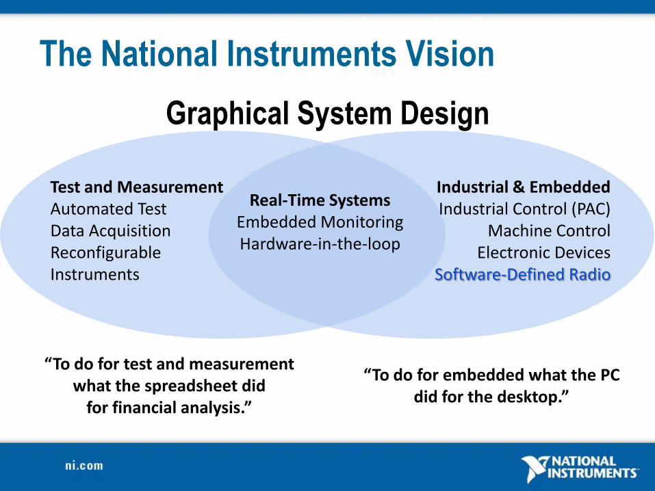
Graphical System Design
The National Instruments Vision
Real-Time Systems
Embedded Monitoring Hardware-in-the-loop
Test and Measurement Automated Test Data Acquisition Reconfigurable Instruments
Industrial & Embedded Industrial Control (PAC)
Machine Control Electronic Devices
Software-Defined Radio
“To do for embedded what the PC did for the desktop.”
“To do for test and measurement what the spreadsheet did
for financial analysis.”

NI RF 6-GHz
Peer-to-Peer
FPGA
RIO Host
Embedded, PC
RF RIO NI FlexRIO
NI-USRP for
LabVIEW
NI RF VSG,
VSA
NI Platforms for RF/Communications
NI USRP-29xx
Powered by Ettus Research

Gigabit Ethernet
Connectivity Plug-and-play capability
Up to 20 MS/s baseband
IQ streaming
Tunable RF Transceiver
Front Ends Frequency Ranges
50 MHz – 2.2 GHz (NI-2920)
2.4 GHz & 5.5 GHz (NI-2921)
Signal Processing
and Synthesis NI LabVIEW to develop
and explore algorithms
NI Modulation Toolkit to
synthesize and process
live signals
Applications FM Radio
TV
GPS
GSM
ZigBee®
Safety Radio
OFDM
Passive Radar
Dynamic Spectrum Access
NI USRP

NI USRP enables Host-based Processing
RF Transceiver
Baseband IQ Host-based Processing

A Compiled Graphical Development Environment
• Intuitive graphical dataflow programming environment with integrated .m file script textual math
• Functionality tailored for science and engineering
• 750+ functions for signal processing, analysis, and mathematics

Hardware APIs
Programming Approaches
Analysis Libraries
Deployment Targets
A Highly Productive Graphical Development Environment for Engineers and Scientists
Custom User Interfaces
Technology Abstractions

From Concept to Prototype … Rapidly!
Concept Design
Language Prototype
Bits I QBits Bits
Bits I QBitsBits
Cha
nnel
Dow
ncon
vers
ion
Dem
odul
atio
n
Cha
nnel
Dec
odin
g
Sou
rce
Dec
odin
gS
ourc
e C
odin
g
Mod
ulat
ion
Upc
onve
rsio
n
Cha
nnel
Cod
ing
Simulation
Data Flow C Code Textual Math Simulation Statechart
Graphical System Design
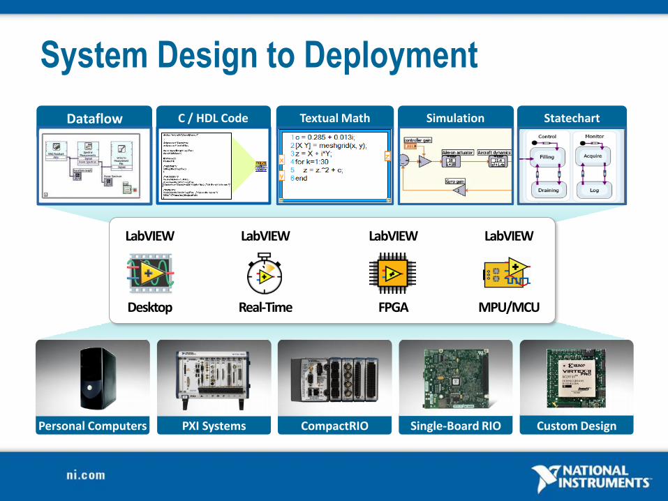
LabVIEW
`̀
Real-Time
LabVIEW
Desktop
LabVIEW
FPGA
LabVIEW
MPU/MCU
System Design to Deployment
Personal Computers PXI Systems CompactRIO Single-Board RIO
Dataflow C / HDL Code Textual Math Simulation Statechart
Custom Design

Large Telescope Mirror Control
Tokamak Plasma Control
CERN Large Hadron Collider
Early Cancer Detection
Solving the Toughest Problems on Earth
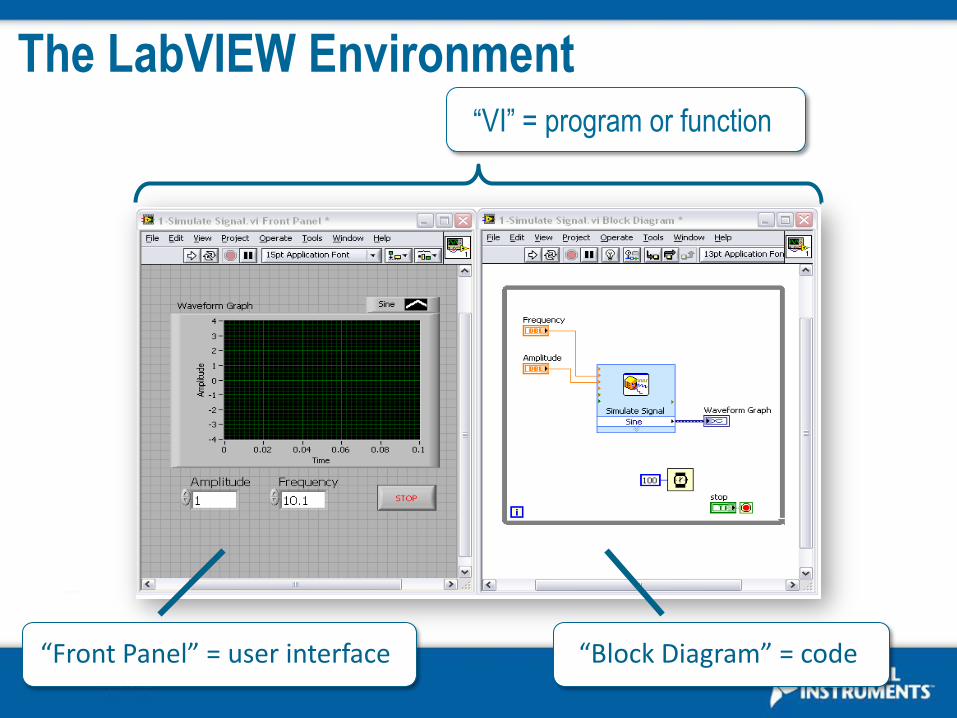
The LabVIEW Environment “VI” = program or function
“Front Panel” = user interface “Block Diagram” = code

Controls & Indicators
• Knobs/Dials
• Graphs/Charts
• Buttons
• Digital Displays
• Sliders
• Thermometers
• Customize and
create your own

Interactivity
Problem Definition
Concept Demos
Computational Exploration
Design
Interactive Analysis

Demo: Simple USRP-based Receiver
Gigabit Ethernet Connection to Host Computer
NI USRP-2190 Receiver
• USRP control (Tx & Rx) • Inline Processing / Display

The G Programming Language
• An intuitive visual representation maps functional blocks to concepts
• Modular and hierarchical
• High-level tools and building blocks
• Reuse external code
• Compiles to machine code
• Directly represents parallel, multithreaded, distributed systems
y[n] = 0.5x2[n] + x[n] + 0.1Un[n]

Functions and Express VIs
Configuration Based
Express VI
Standard VIs

Wires and Data Types
• Transfer data between block diagram objects
through wires
• Wires are different colors, styles, and thicknesses,
depending on their data types
• A broken wire appears as a dashed
black line with a red X in the middle
Scalar 1D Array 2D Array
DBL Numeric Integer Numeric String

Data Flow Sets Execution Order
• Block diagram execution order depends on the flow of data
• Block diagram does NOT execute left to right
• Nodes executes when data is available to ALL input terminals
• Nodes supply data to all output terminals when done
• If the computer running this code had multiple processors, these two pieces of code could run independently without additional coding

Execution Control Structures
While Loop For Loop
Run until stop
condition met Run N times
• Allow same piece of code to run multiple times
• Exit conditions different for each

Modularity and SubVIs
26
Function Code Calling Program Code function average (in1, in2, out)
{
out = (in1 + in2)/2.0;
}
main
{
average (point1, point2,
pointavg);
}
SubVI Block Diagram Calling VI Block Diagram

Demo: Simple USRP-based Receiver
• with Spectrum Analysis
Gigabit Ethernet Connection to Host Computer
NI USRP-2190 Receiver
• USRP control (Rx) • Inline Processing / Display

• Signal Processing & Analysis – Waveform Generation
– Waveform Conditioning
– Waveform Monitoring
– Waveform Measurements
– Signal Generation
– Signal Operations
– Windows
– Digital Filters
– Spectral Analysis
– Transforms
– Point-by-Point
• Mathematics – Numeric
– Elementary and Special Functions
– BLAS/LAPAC-based Linear Algebra
– Curve Fitting
– Interpolation/Extrapolation
– Probability and Statistics
– Optimization
– Ordinary Differential Equations
– Geometry
– Polynomial
– Formula Parsing
– 1D & 2D Evaluation
– Calculus
LabVIEW Signal Processing, Analysis and Math
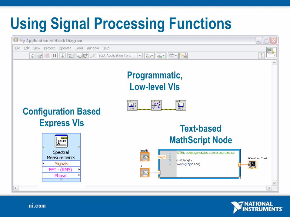
Using Signal Processing Functions
Configuration Based
Express VIs
Programmatic,
Low-level VIs
Text-based
MathScript Node

Demo: Simple USRP-based Receiver
• with Spectrum Analysis
• with live FM radio
Gigabit Ethernet
Connection to Host Computer
NI USRP-2190
Receiver
• USRP control (Rx)
• Inline Processing / Display

Decode & Hear Live FM Radio
30 Hz
15 kHz
23 kHz
38 kHz
53 kHz
58.35 kHz
67.65 kHz
76.65 kHz
92 kHz
99 kHz
57 kHz
0
19kHz Stereo Pilot (10%)
Stereo Audio Left - Right
Direct Band (10%)
RBDS (5%)
Mono Audio
Left + Right
Audos Subcarrier (10%)

NI-USRP Driver Software
Initialize Configure Start Read IQ Stop Close

NI-USRP Driver Software
Initialize Configure Start Read IQ Stop Close

Demo: Simple USRP-based Tx / Rx Pair
Gigabit Ethernet
Connections to Host Computer
NI USRP-2190
Receiver
• USRP control (Tx/Rx)
• Inline Processing / Display
NI USRP-2190
Transmitter

Text-based signal processing, analysis, and math within LabVIEW 750 built-in functions / user-defined
functions
Reuse many of your .m file scripts created with The MathWorks, Inc. MATLAB® software and others
Based on original math from NI MATRIXx software
A native LabVIEW solution Interactive and programmatic
interfaces
Does not require 3rd-party software
Enables hybrid programming MATLAB® is a registered trademark of The MathWorks, Inc. All other
trademarks are the property of their respective owners.
MathScript RT Module
• 2D and 3D Plotting /
Visualization
• Probability and Statistics
• Digital Signal Processing (DSP)
• Optimization
• Approximation (Curve Fitting /
Interpolation)
• Advanced Functions
• Ordinary Differential
• Equations
• Basic Operations
• Polynomial Operations
• Trigonometric
• Linear Algebra
• Matrix Operations
• Boolean and Bit Operations
• Data Acquisition /
Generation
• Vector Operations
• Other

The Hybrid Approach Combine Graphical / Textual Programming

Digital Communication System
Sou
rce
Co
din
g
Ch
ann
el C
od
ing
Mo
du
lati
on
Up
con
vers
ion
Do
wn
con
vers
ion
De
mo
du
lati
on
Ch
ann
el D
eco
din
g
Sou
rce
De
cod
ing
Communications Channel

NI Modulation Toolkit
NI Modulation Toolkit
Digital Communication System
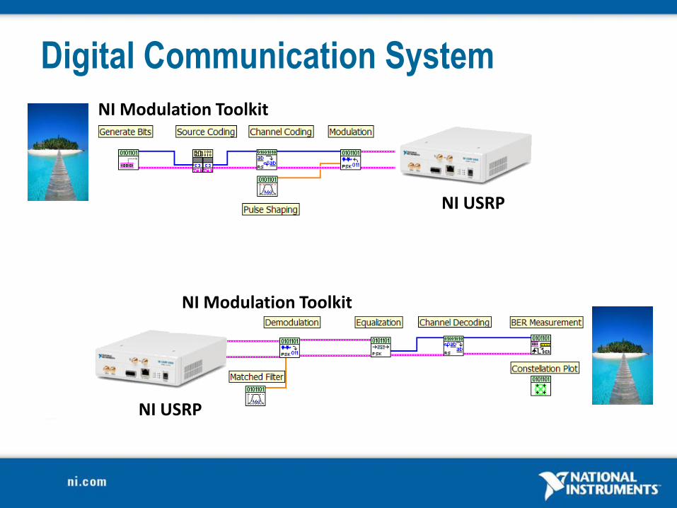
NI Modulation Toolkit
NI Modulation Toolkit
NI USRP
NI USRP
Digital Communication System

Modulation Toolkit
Modulation & Demodulation
Channel models / impairments
Channel coding
Communication visualization
LabVIEW simulation and modeling tools for communication system design

Demo: QAM Tx / Rx Pair
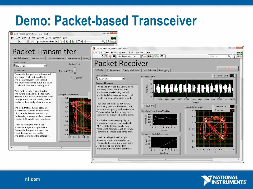
Demo: Packet-based Transceiver

Demo: Packet-based Link
NI USRP-2190 Receiver
• USRP control (Tx & Rx) • Modulate Tx signal • Demodulate Rx signal • Reconstruct message
NI USRP-2190 Transmitter RF Signal
915MHz , PSK packets, 400kbps

Transmitter Block Diagram

Packet Structure
GUARD
BAND SYNC
SEQ PCKT
NUM PAD DATA
Field Length
[bits]
Description
Guard Band 30 Allow initialization of Rx PLL, filters, etc
Sync Sequence 20 Frame and Symbol Synchronization
Packet Number 8 Range: 0-255 Used for reordering of packets
and detection of missing packets
Data 64 - 256 Variable length data field. Length detected
dynamically at Rx end
Pad 20 Allows for filter edge effects.

The Received Signal

Receiver Block Diagram
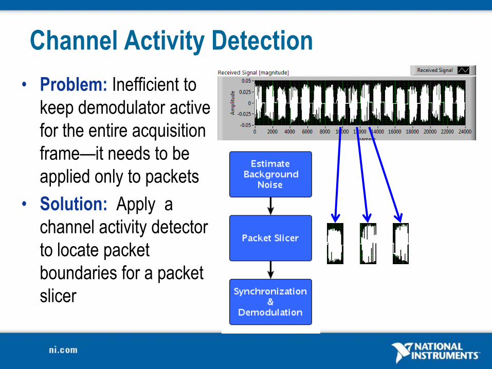
Channel Activity Detection
• Problem: Inefficient to
keep demodulator active
for the entire acquisition
frame—it needs to be
applied only to packets
• Solution: Apply a
channel activity detector
to locate packet
boundaries for a packet
slicer

Error Tolerance
Problem: Errors at SNR >> 1
Partial packets captured at
frame edges
Improper synchronization
Solution: Repetition Coding
Repeat each packet n times
Repeat entire message m
times
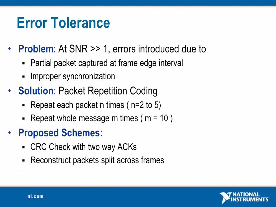
Error Tolerance
• Problem: At SNR >> 1, errors introduced due to
Partial packet captured at frame edge interval
Improper synchronization
• Solution: Packet Repetition Coding
Repeat each packet n times ( n=2 to 5)
Repeat whole message m times ( m = 10 )
• Proposed Schemes:
CRC Check with two way ACKs
Reconstruct packets split across frames

Ideas for Extension
• Improved Error Tolerance CRC check, convolutional coding,
interleaving, etc…
• Bi-directional link with ACK messages
• OFDM
• Channel Equalization to improve range
• SW-based Rx gain control to ensure full use of available dynamic range
• Monitor / replicate common links Bluetooth mouse
Key fob
• Additional message choices Images, video, etc.

Next Steps
• Learn more about LabVIEW and NI-USRP
www.ni.com/usrp
• Find NI-USRP examples & participate in the NI-USRP
online community
decibel.ni.com/content/groups/ni-usrp-example-labview-vis