A Project Report on Solar Sunseekar
49
A PROJECT REPORT ON SOLAR SUN SEEKER Submitted in partial fulfillment of the requirements For the award of the degree BACHELOR OF ENGINEERING IN ____________________________________ ENGINEERING SUBMITTED BY -------------------- (--------------) --------------------- (---------------) --------------------- (---------------) DEPARTMENT OF _______________________ ENGINEERING __________COLLEGE OF ENGINEERING 1
-
Upload
tirthankar-mohanty -
Category
Documents
-
view
41 -
download
8
Transcript of A Project Report on Solar Sunseekar
A PROJECT REPORT ON
SOLAR SUN SEEKER
Submitted in partial fulfillment of the requirements
For the award of the degree
BACHELOR OF ENGINEERING
IN
____________________________________ ENGINEERING
SUBMITTED BY
-------------------- (--------------)--------------------- (---------------)--------------------- (---------------)
DEPARTMENT OF _______________________ ENGINEERING__________COLLEGE OF ENGINEERING
AFFILIATED TO ___________ UNIVERSITY
1
CERTIFICATE
This is to certify that the dissertation work entitled SOLAR SUN SEEKER is the work done by
_______________________________________________submitted in partial
fulfillment for the award of ‘BACHELOR OF ENGINEERING (B.Tech)’in
__________________________Engineering from ______________ College of
Engineering affiliated to _________ University, Bhubaneswar.
________________ ____________(Head of the department, MECH) (Assistant Professor)
EXTERNAL EXAMINER
2
ACKNOWLEDGEMENT
The satisfaction and euphoria that accompany the successful completion of
any task would be incomplete without the mentioning of the people whose
constant guidance and encouragement made it possible. We take pleasure in
presenting before you, our project, which is result of studied blend of both
research and knowledge.
We express our earnest gratitude to our internal guide, Assistant Professor
______________, Department of Mechanical, our project guide, for his
constant support, encouragement and guidance. We are grateful for his
cooperation and his valuable suggestions.
Finally, we express our gratitude to all other members who are involved
either directly or indirectly for the completion of this project.
1
DECLARATION
We, the undersigned, declare that the project entitled ‘SOLAR SUN
SEEKER ’, being submitted in partial fulfillment for the award of Bachelor
of Engineering Degree in Mechanical Engineering, affiliated to _________
University, is the work carried out by us.
__________ _________ _________ __________ _________ _________
2
CHAPTER 1
INTRODUCTION
Solar panels harness the energy of the sun light and convert it into usable electricity. In
this article, we are going to have a detailed look at the theory behind the basic principle
used in solar panels and how it will store maximum energy by tracking the sun’s
movement with a mechanical arrangement.
Solar cells are designed in conjunction with concentrators which contain lenses or mirrors
to focus the light on to tightly packed and coupled array of solar cells. Although there is
an increase in the design and implementation of the solar panels in terms of high cost per
unit area, the basic motto of increase in efficiency is achieved with least efforts. Thus the
science and technology behind solar panels is increasing by the day and advancement in
the same is occurring at a rapid pace.
3

1.0 OBJECTIVES OF WORK
The objective of the proposed work is to present an analysis of the working of solar sun
seeker. Detail scope of this work includes:
Explanation of the principles and working of solar panel.
Finding ways and methods to improve the efficiency of the solar panel.
Suggesting potential new materials which will have properties better suited to
increase the value of the figure of merit. .
Various applications and fields in which solar sun seeker systems are used
presently and the overall effectiveness of these devices is also discussed.
4
1.1 LAY-OUT OF THE REPORT
A brief description of all the chapters is given below:
Chapter first gives a brief introduction working of solar panel.
Chapter 2 High torque dc motors
Chapter 3 Performance of a solar panel with the arrangement
Chapter 4 Explanation of electronics components used in the project
Chapter 5 Gear arrangement.
Finally Chapter 6 gives the conclusion based on the study and the scope of future
development of the project.
5
CHAPTER 1
INTRODUCTION
Photons are the basic fundamental unit of any form of light energy. The photons that are
emitted by the sun (visible light) are captured by the solar panels. The generation of
electricity in the solar panels is possible because of a principle called as photovoltaic
effect.
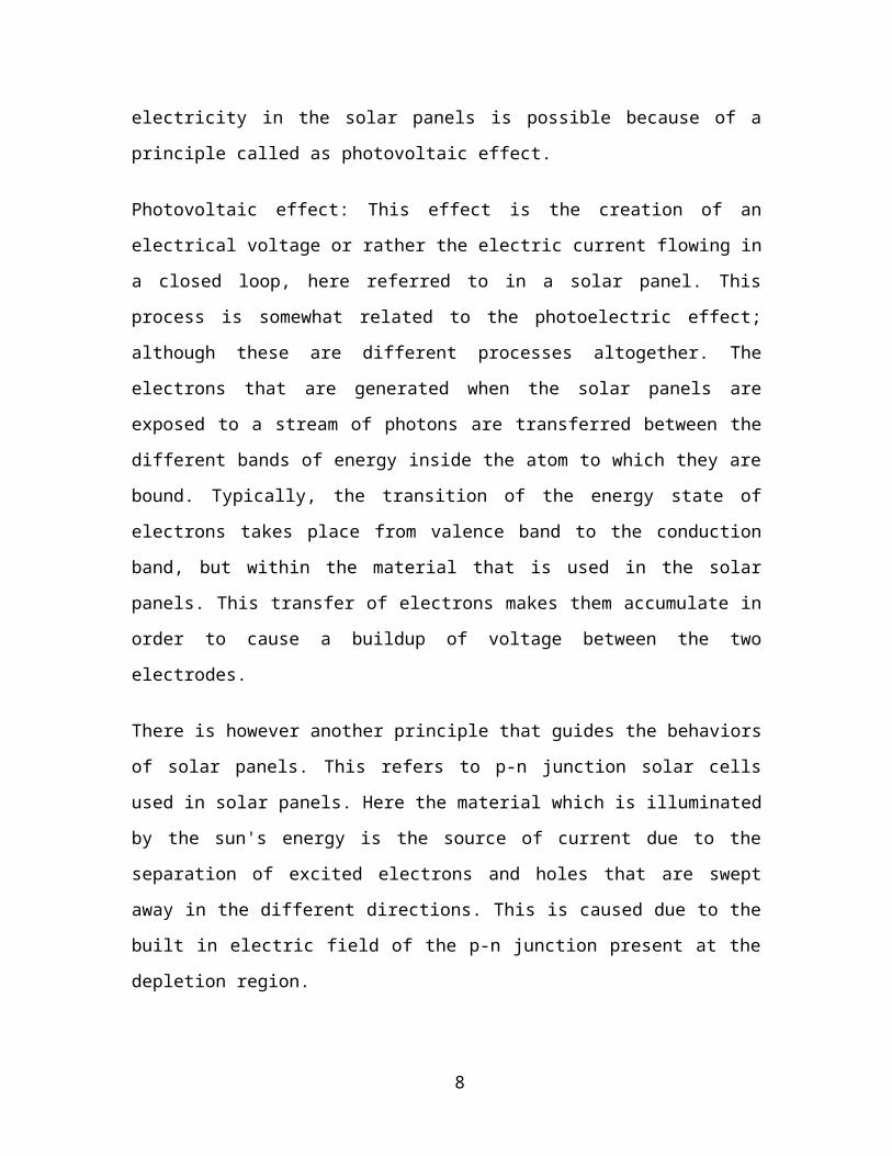
Photovoltaic effect: This effect is the creation of an electrical voltage or rather the electric
current flowing in a closed loop, here referred to in a solar panel. This process is
somewhat related to the photoelectric effect; although these are different processes
altogether. The electrons that are generated when the solar panels are exposed to a stream
of photons are transferred between the different bands of energy inside the atom to which
they are bound. Typically, the transition of the energy state of electrons takes place from
valence band to the conduction band, but within the material that is used in the solar
panels. This transfer of electrons makes them accumulate in order to cause a buildup of
voltage between the two electrodes.
There is however another principle that guides the behaviors of solar panels. This refers
to p-n junction solar cells used in solar panels. Here the material which is illuminated by
the sun's energy is the source of current due to the separation of excited electrons and
holes that are swept away in the different directions. This is caused due to the built in
electric field of the p-n junction present at the depletion region.
Solar panels contain a system of solar cells that are interconnected so that they can
transfer the induced voltage/current between one another so that the required parameters
can pile up and a suitable throughout can be obtained. Series connections of solar cells in
solar panels help add up the voltage and the same is true for solar cells connected using
parallel connection.
Solar cells are protected from the mechanical damage as well as external factors like dust
and moisture that can be severe to degrade their performance. Solar cells have materials
6

that are mostly rigid. But when it comes to the thin films, they need extra care as they are
available in semi-flexible nature.
It all depends upon how the solar panels are designed and manufactured. These factors
help them produce electricity from a range of frequencies of light. Solar panels cannot be
designed practically in order to capture photons of the entire spectrum of light emitted by
the sun. Capabilities of solar panels that capture rage of frequencies mostly exclude the
infrared, ultraviolet etc. and a poor performance is witnessed in the low or diffused light.
Another fact is that solar panels produce much lesser efficiency as compared to when
their basic components viz. solar cells are used independently without any
interconnections. Typically, solar panels that are available commercially are only able to
depict their best efficiency as low as 21%. Due to the significant impact of efficiency, a
number of techniques are used in order to tweak the performance of solar cells.
Solar Power Generation
7
• Photovoltaic cells are capable of directly converting sunlight into electricity.
• A simple wafer of silicon with wires attached to the layers. Current is produced
based on types of silicon (n- and p-types) used for the layers. Each cell=0.5 volts.
• Battery needed as storage
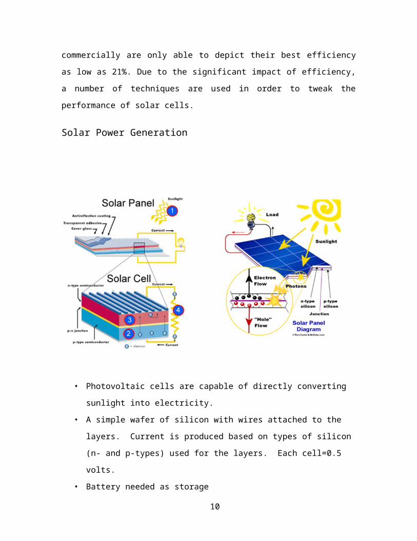
• No moving partsàdo no wear out, but because they are exposed to the weather,
their lifespan is about 20 years.
Solar array selection
The amount of solar cells needed was determined by the energy requirements of the
thermoelectric refrigerator. The solar cells were connected in series and in parallel ways
in order to supply enough voltage to drive the thermoelectric cooling module and power
the fan. Overall, the main objective of the solar cells array system is to provide the
maximum power to the thermoelectric module. Each cell gives 0.5 V and 3.6 A. In this
study, 64 single crystalline silicon solar cells were used. They were distributed on two
sides in such a way that each side contained 32 cells. The cells on each side were
8
arranged in parallel and series, to produce a maximum voltage of 12 V and a maximum
current of 14.4 A.
Solar array arrangements.
.
9

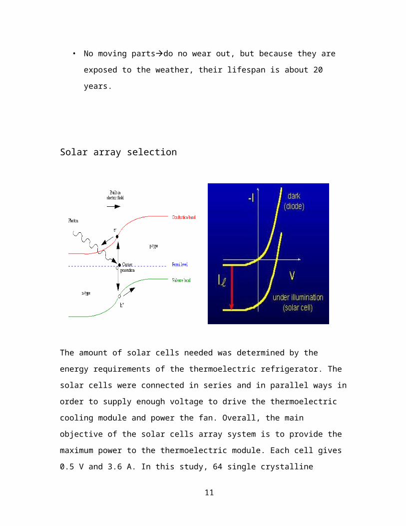
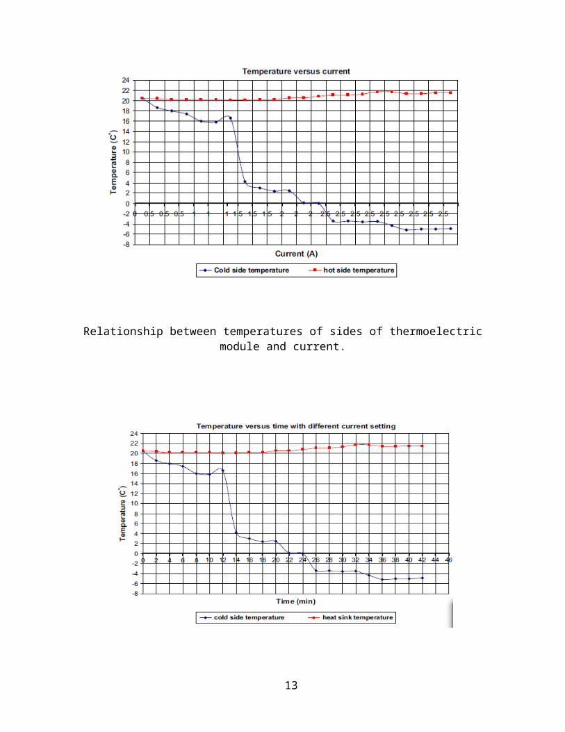
Relationship between temperatures of sides of thermoelectric module and current.
Temperature variation with time at different electric current.
10
Theoretical consideration
The rate of heat transfer between the hot side of the module and the surface of the heat sink can be calculated as
where R1 ¼ L=kAs; k is the heat conductivity of the aluminum; L is the thickness of the
heat sink base; As is the contact surface area between the module and the heat sink base;
Tb is the temperature of the base which will be the same as the temperature of the hot
side of the module assuming no losses through the heat sink compound; T1 is the
temperature of the other side of the base. The rate of heat transfer from the other side of
the base through the fins to the air can be calculated as
where ‘A’ is the total surface area of the fins; ‘h’ is the heat transfer coefficient of the air;
‘TN’ is the temperature of the ambient air. The calculation of the cooling rate inside the
cabinet of the refrigerator can be calculated as
where ‘As’ is the heat transfer surface area of the aluminum; ‘Ts’ is the aluminum
surface temperature; ‘Ta’ is the ambient temperature of the air inside the cabinet of the
refrigerator.
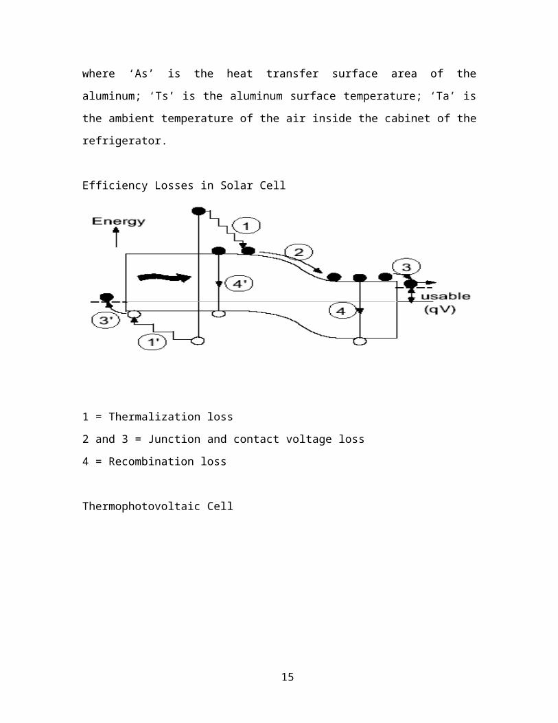
Efficiency Losses in Solar Cell
11
1 = Thermalization loss
2 and 3 = Junction and contact voltage loss
4 = Recombination loss
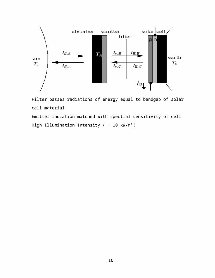
Thermophotovoltaic Cell
Filter passes radiations of energy equal to bandgap of solar cell material
Emitter radiation matched with spectral sensitivity of cell
High Illumination Intensity ( ~ 10 kW/m2 )
12

CHAPTER 2
D.C. Motors
13
IntroductionD. C. motors are seldom used in ordinary applications because all electric supply
companies furnish alternating current However, for special applications such as in steel
mills, mines and electric trains, it is advantageous to convert alternating current into
direct current in order to use d.c. motors. The reason is that speed/torque characteristics
of d.c. motors are much more superior to that of a.c. motors. Therefore, it is not
surprising to note that for industrial drives, d.c. motors are as popular as 3-phase
induction motors. Like d.c. generators, d.c. motors are also of three types viz., series-
wound, shunt-wound and compound wound. The use of a particular motor depends upon
the mechanical load it has to drive.
D.C. Motor PrincipleA machine that converts d.c. power into mechanical power is known as a d.c. motor. Its
operation is based on the principle that when a current carrying conductor is placed in a
magnetic field, the conductor experiences a mechanical force. The direction of this force
is given by Fleming’s left hand rule and magnitude is given by;
F BInewtons
14

Basically, there is no constructional difference between a d.c. motor and a d.c. generator.
The same d.c. machine can be run as a generator or motor.
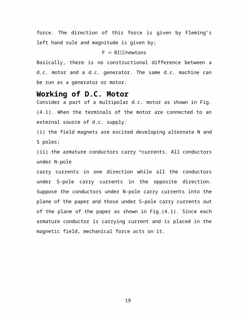
Working of D.C. MotorConsider a part of a multipolar d.c. motor as shown in Fig. (4.1). When the terminals of
the motor are connected to an external source of d.c. supply:
(i) the field magnets are excited developing alternate N and S poles;
(ii) the armature conductors carry ^currents. All conductors under N-pole
carry currents in one direction while all the conductors under S-pole carry currents in the
opposite direction. Suppose the conductors under N-pole carry currents into the plane of
the paper and those under S-pole carry currents out of the plane of the paper as shown in
Fig.(4.1). Since each armature conductor is carrying current and is placed in the magnetic
field, mechanical force acts on it.
Fig. (4.1)
Referring to Fig. (4.1) and applying Fleming’s left hand rule, it is clear that force on each
conductor is tending to rotate the armature in anticlockwise direction. All these forces
add together to produce a driving torque which sets the armature rotating. When the
conductor moves from one side of a brush to the other, the current in that conductor is
reversed and at the same time it comes under the influence of next pole which is of
15
opposite polarity. Consequently, the direction of force on the conductor remains the
same.
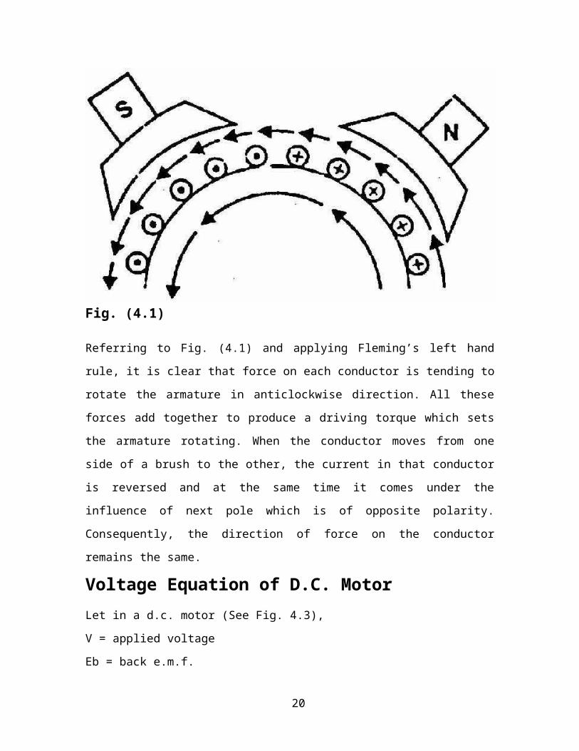
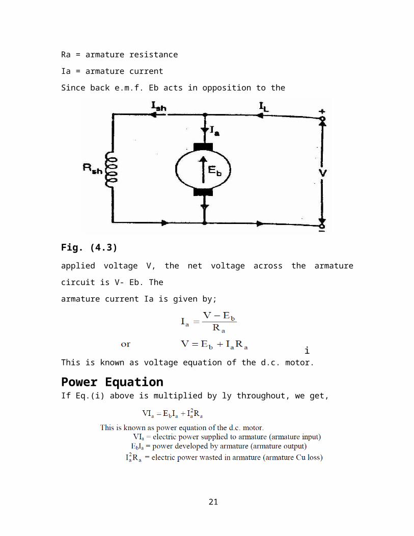
Voltage Equation of D.C. Motor
Let in a d.c. motor (See Fig. 4.3),
V = applied voltage
Eb = back e.m.f.
Ra = armature resistance
Ia = armature current
Since back e.m.f. Eb acts in opposition to the
Fig. (4.3)
applied voltage V, the net voltage across the armature circuit is V- Eb. The
armature current Ia is given by;
iThis is known as voltage equation of the d.c. motor.
Power EquationIf Eq.(i) above is multiplied by ly throughout, we get,
16
Thus out of the armature input, a small portion (about 5%) is wasted as a
2a I R and the remaining portion EbIa is converted into mechanical power within the
armature
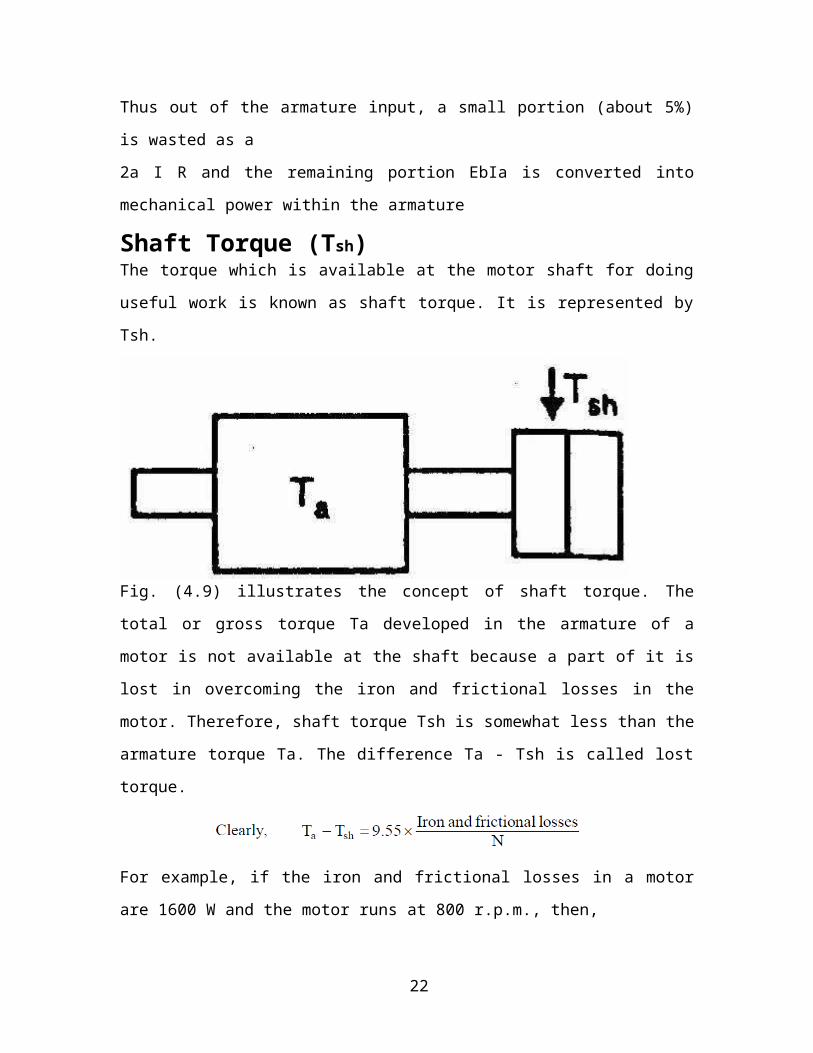
Shaft Torque (Tsh)The torque which is available at the motor shaft for doing useful work is known as shaft
torque. It is represented by Tsh.
Fig. (4.9) illustrates the concept of shaft torque. The total or gross torque Ta developed in
the armature of a motor is not available at the shaft because a part of it is lost in
overcoming the iron and frictional losses in the motor. Therefore, shaft torque Tsh is
somewhat less than the armature torque Ta. The difference Ta - Tsh is called lost torque.
For example, if the iron and frictional losses in a motor are 1600 W and the motor runs at
800 r.p.m., then,
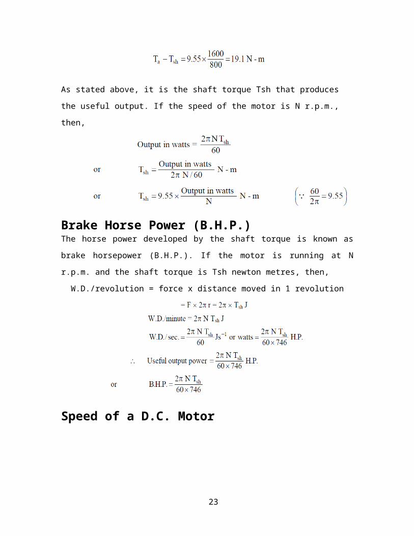
As stated above, it is the shaft torque Tsh that produces the useful output. If the speed of
the motor is N r.p.m., then,
17
Brake Horse Power (B.H.P.)The horse power developed by the shaft torque is known as brake horsepower (B.H.P.). If
the motor is running at N r.p.m. and the shaft torque is Tsh newton metres, then,
W.D./revolution = force x distance moved in 1 revolution
Speed of a D.C. Motor
18
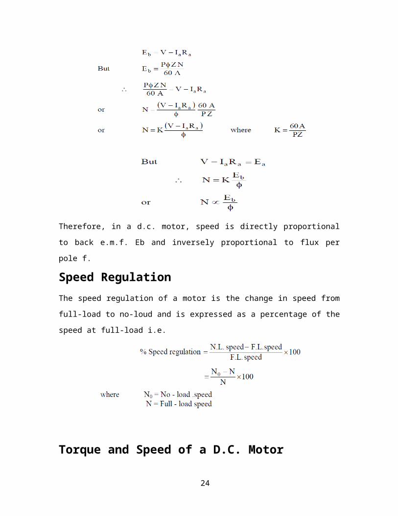
Therefore, in a d.c. motor, speed is directly proportional to back e.m.f. Eb and inversely
proportional to flux per pole f.
Speed Regulation
The speed regulation of a motor is the change in speed from full-load to no-loud and is
expressed as a percentage of the speed at full-load i.e.
Torque and Speed of a D.C. Motor
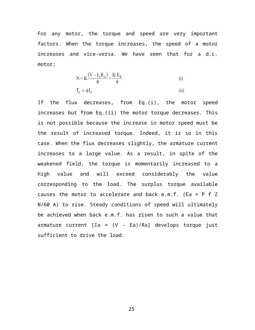
For any motor, the torque and speed are very important factors. When the torque
increases, the speed of a motor increases and vice-versa. We have seen that for a d.c.
motor;
If the flux decreases, from Eq.(i), the motor speed increases but from Eq.(ii) the motor
torque decreases. This is not possible because the increase in motor speed must be the
result of increased torque. Indeed, it is so in this case. When the flux decreases slightly,
the armature current increases to a large value. As a result, in spite of the weakened field,
the torque is momentarily increased to a high value and will exceed considerably the
19
value corresponding to the load. The surplus torque available causes the motor to
accelerate and back e.m.f. (Ea = P f Z N/60 A) to rise. Steady conditions of speed will
ultimately be achieved when back e.m.f. has risen to such a value that armature current
[Ia = (V - Ea)/Ra] develops torque just sufficient to drive the load.
CHAPTER 4
Explanation of electronics components used in the project
20
Explanation of electronics components
The main objective of this project is to track the sun and rotate the solar panel
accordingly, to receive sunlight to the fullest extent always during the day time. This
movement is achieved by interfacing a stepper motor to the solar panel that changes its
direction according to the positioning of the sun. This is achieved using time reference
that controls the movement time for 12 hours by a program written in such a way that for
every given time the solar panel faces to the sun to generate maximum power which is
stored in batteries and future use.
HARDWARE COMPONENTS:
1. TRANSFORMER
2. VOLTAGE REGULATOR (LM 7805)
3. RECTIFIER
4. FILTER
5. MICROCONTROLLER (AT89S52/AT89C51)
6. LED
7. RTC
8. BC547
9. 1N4007
21
10. RESISTOR
11. CAPACITOR
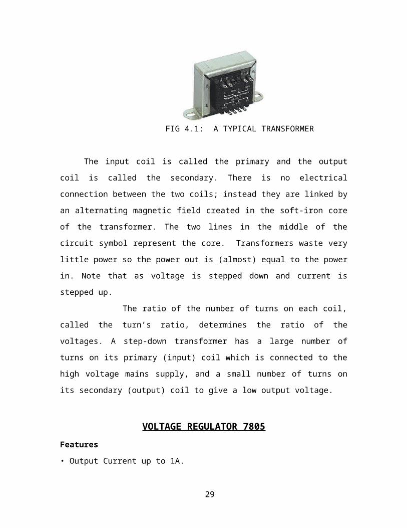
TRANSFORMER
Transformers convert AC electricity from one voltage to another with a little loss of
power. Step-up transformers increase voltage, step-down transformers reduce voltage.
Most power supplies use a step-down transformer to reduce the dangerously high voltage
to a safer low voltage.
FIG 4.1: A TYPICAL TRANSFORMER
The input coil is called the primary and the output coil is called the secondary.
There is no electrical connection between the two coils; instead they are linked by an
alternating magnetic field created in the soft-iron core of the transformer. The two lines
in the middle of the circuit symbol represent the core. Transformers waste very little
power so the power out is (almost) equal to the power in. Note that as voltage is stepped
down and current is stepped up.
22
The ratio of the number of turns on each coil, called the turn’s ratio, determines
the ratio of the voltages. A step-down transformer has a large number of turns on its
primary (input) coil which is connected to the high voltage mains supply, and a small
number of turns on its secondary (output) coil to give a low output voltage.
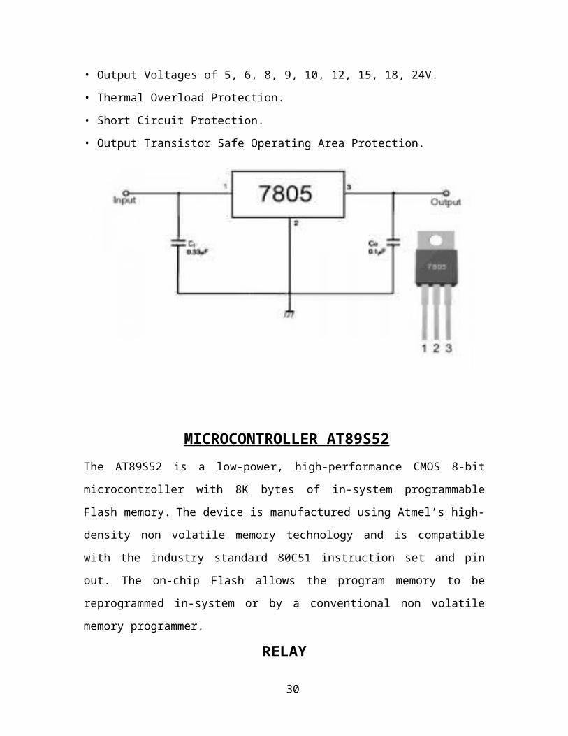
VOLTAGE REGULATOR 7805
Features
• Output Current up to 1A.
• Output Voltages of 5, 6, 8, 9, 10, 12, 15, 18, 24V.
• Thermal Overload Protection.
• Short Circuit Protection.
• Output Transistor Safe Operating Area Protection.
MICROCONTROLLER AT89S52
The AT89S52 is a low-power, high-performance CMOS 8-bit microcontroller with 8K
bytes of in-system programmable Flash memory. The device is manufactured using
Atmel’s high-density non volatile memory technology and is compatible with the
industry standard 80C51 instruction set and pin out. The on-chip Flash allows the
23
program memory to be reprogrammed in-system or by a conventional non volatile
memory programmer.
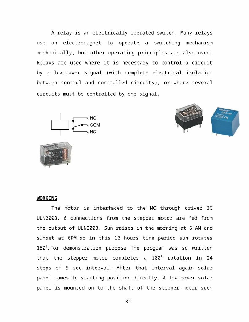
RELAY
A relay is an electrically operated switch. Many relays use an electromagnet to
operate a switching mechanism mechanically, but other operating principles are also
used. Relays are used where it is necessary to control a circuit by a low-power signal
(with complete electrical isolation between control and controlled circuits), or where
several circuits must be controlled by one signal.
WORKING
The motor is interfaced to the MC through driver IC ULN2003. 6 connections
from the stepper motor are fed from the output of ULN2003. Sun raises in the morning at
6 AM and sunset at 6PM.so in this 12 hours time period sun rotates 1800.For
demonstration purpose The program was so written that the stepper motor completes a
1800 rotation in 24 steps of 5 sec interval. After that interval again solar panel comes to
starting position directly. A low power solar panel is mounted on to the shaft of the
stepper motor such that the phase of the solar panel faces the sun in 900 incidence
throughout the day.
24
CHAPTER 5
Gear arrangement
25
Gears– General Gearing Arrangements
Gear trains and gearing linkage exists in many aspects of aerospace mechanisms. Gearing
systems are also part of any electromechanical actuator design. Gearing systems at their
simplest consist of 2 gears. When 2 gears are not sufficient due to size, volume or
strength constraints, a multi-gear train or a compound gear train is required. When a large
gear ratio is desired within a small volume, then a planetary gear arrangement is required.
Designs of these types of gear trains are discussed below. Other gearing arrangements–
rack & pinion, bevel and worm gears are also presented below. The same principles for
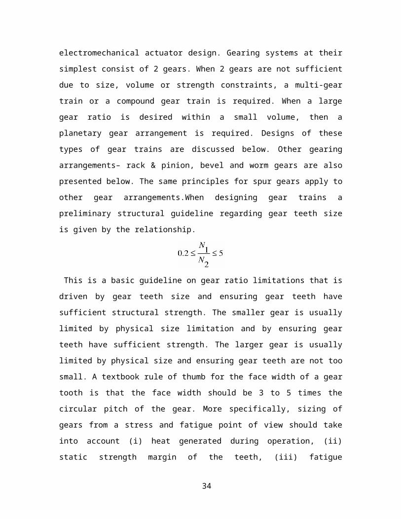
spur gears apply to other gear arrangements.When designing gear trains a preliminary
structural guideline regarding gear teeth size is given by the relationship.
This is a basic guideline on gear ratio limitations that is driven by gear teeth size and
ensuring gear teeth have sufficient structural strength. The smaller gear is usually limited
by physical size limitation and by ensuring gear teeth have sufficient strength. The larger
gear is usually limited by physical size and ensuring gear teeth are not too small. A
textbook rule of thumb for the face width of a gear tooth is that the face width should be
3 to 5 times the circular pitch of the gear. More specifically, sizing of gears from a stress
and fatigue point of view should take into account (i) heat generated during operation, (ii)
static strength margin of the teeth, (iii) fatigue capability, (iv) abrasive wear
characteristics of the gear material over the expected life, and (v) noise/vibration affects
26

during operation. Gear teeth can be analyzed structurally treating each tooth has a
cantilever beam. Special formulas are available in various gear design handbooks and
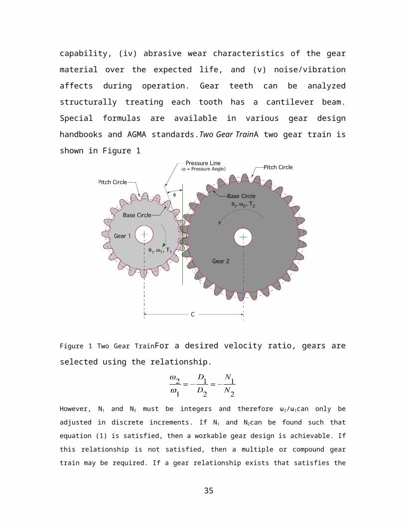
AGMA standards.Two Gear TrainA two gear train is shown in Figure 1
Figure 1 Two Gear TrainFor a desired velocity ratio, gears are selected using the
relationship.
However, N1 and N2 must be integers and therefore ω2/ω1can only be adjusted in discrete
increments. If N1 and N2can be found such that equation (1) is satisfied, then a workable gear
design is achievable. If this relationship is not satisfied, then a multiple or compound gear train
may be required. If a gear relationship exists that satisfies the constraints, then the pitch diameter
can be chosen using N1 and N2, followed by the remaining gear parameters. Stress analysis must
also be performed using expected loads in service to validate gear teeth sizing.
Results can be used to select gears from vendor catalogs or gear drawings can be created for
manufacture. Using non-standard gears, it is possible to have non-integer values of gear teeth
per inch.
Multi Gear Train ArrangementMulti-gear trains are used when input and output shafts are far
apart and space/design considerations do not allow for 2 large gears. Multi-gear trains are also
used when more than 1 shaft must be driven at different speeds. Multi-gear trains are required to
27
provide a + or – direction of the output gear relative to the input gear (2 gear trains always have
input and output gears rotating in opposite directions).
For a design example, consider a 3 gear train shown in Figure 2.
Velocity ratios for a multi-gear train are computed in the same manner as a two gear train.
However, the only 2 gears that matter when computing the overall gear ratio is the first and last
gear [see equation (5)]. Intermediate gears do not have any effect on the overall velocity ratio and
are called “idler gears”. If an intermediate gear was used to drive a 2nd shaft, the 2nd shaft would
have a different velocity ratio. Design principles for each pair of gears in a multi-gear train are the
same as a two gear train where tooth ratios should be within the constraints of equation (1).
Compound Gear Train Arrangement
28

A compound gear is a gear where 2 or more gears are rigidly attached, such that they rotate at
the same speed. Compound gear trains are used when the velocity ratio is outside of the 0.2 – 5
range and space is limited. An example compound gear train is shown in Figure 3.
An iterative process is required to design a compound gear train. To design a compound gear
train, the general steps are as follows:
Select number of stages, ns. A stage is the number of gear meshes between compound gears. For example, for the compound gear train shown in Figure 3, the number of stages is 3.
Using the desired overall velocity ratio
, compute the velocity ratio for each stage using
If the ps ratio is outside of the 0.2 to 5 range, increase ns and recompute ps
29
Choose a ratio for the number of teeth for each stage such that the ratio is close to ps. Referring to Figure 3, the teeth ratios (N1/N2), (N3/N4), and (N5/N6) would need to be chosen.
Choose gear tooth numbers for other stages such that the gear tooth ratio is close to ps and the total velocity ratio is equal to pt
Choose a diametrical pitch for each gear pair (preferably the same for all gear pairs). Compute the pitch diameters using
(7)
Iterate as required until results are satisfactory
Bevel GearsA bevel gear arrangement is shown in Figure 4. Bevel gears provide a change in
direction between the input and output shafts. Figure 4 shows a 90 degree change in direction,
but other angles are possible.
Figure 4 Bevel Gear Arrangement
30
The kinematic nomenclature for a bevel gear arrangement is shown in Figure 5. This figure
shows a bevel gear arrangement that has a shaft angle different than 90°.
Figure 5 Bevel Gear Kinematics
In Figure 5, αpand αg are the pitch angles for the pinion and output gear, respectively. The shaft
angle, γ, is the sum of , αp and αg. The pitch radiuses are given by rpinion and rgear. For bevel gears,
the pitch radius is normally specified at the larger end of the teeth. The pitch cone for each gear
represents the area between the root and end of the teeth. Similar to spur gears, the velocity ratio
is computed as.
When designing bevel gears, the shaft angle and number of teeth on each gear are usually
known up front. The corresponding pitch angles can be computed using
and
Rack & Pinion Gears
31
A rack and pinion gear arrangement converts rotary motion from a pinion to linear motion of a
rack.
Figure 6 shows a picture of a rack and pinion.
Figure 6 Rack and Pinion Gear Arrangement
The kinematic relationships for rack and pinion gear arrangements are similar to spur gears.
Figure 7 shows the basic definitions for a rack and pinion gearset.
Figure 7 Kinematic Definitions for Rack and Pinion Gearset
32

For a rack and pinion to mesh together properly, the pitch of rack and pinion must be equal,
i.e.,ppinion = prack. The gear ratio equation is given by
Note that the number of teeth on the rack is not relevant to the velocity ratio. The linear speed of
the rack is simply a function of the pinion pitch radius and the angular velocity of the pinion.
33
CHAPTER 6
Conclusion
34
Conclusion
The project performs the required functions envisioned at the proposal phase. However,
while satisfied with software operation and simulation, less satisfaction was obtained
from two hardware areas. First, there is a potential for problems with motor/photocell
movement due to the photocell wires creating binding issues. There are two wires
attached to the photocell mounted on the motor shaft. Once the tracker has moved
approximately 30 to 45 degrees, the wires place a counter torque on the motor and the
motor slips. This creates positioning error. The present work around for this is to hold the
photocell wires in a way as to keep them perpendicular to the rear of the photocell as the
tracker moves. This problem will be discussed further in Section.
For instance, power from our project is delivered to the grid at the schedule of the sun’s
cycles. Time based rate fees from utilities make it advantageous to control the time when
power is delivered to the utility.
35
36