
A Practical Microcylinder Appearance Model for Cloth...
12
14 A Practical Microcylinder Appearance Model for Cloth Rendering IMAN SADEGHI, OLEG BISKER, JOACHIM DE DEKEN, and HENRIK WANN JENSEN University of California, San Diego This article introduces a practical shading model for cloth that can simu- late both anisotropic highlights as well as the complex color shifts seen in cloth made of different colored threads. Our model is based on extensive Bidirectional Reflectance Distribution Function (BRDF) measurements of several cloth samples. We have also measured the scattering profile of sev- eral different individual cloth threads. Based on these measurements, we derived an empirical shading model capable of predicting the light scatter- ing profile of a variety of threads. From individual threads, we synthesized a woven cloth model, which provides an intuitive description of the layout of the constituent threads as well as their tangent directions. Our model is physically plausible, accounting for shadowing and masking by the threads. We validate our model by comparing predicted and measured light scatter- ing values and show how it can reproduce the appearance of many cloth and thread types, including silk, velvet, linen, and polyester. The model is robust, easy to use, and can simulate the appearance of complex highlights and color shifts that cannot be fully handled by existing models. Categories and Subject Descriptors: I.3.3 [Computer Graphics]: Picture/ Image Generation; I.3.7 [Computer Graphics]: Three-Dimensional Graph- ics and Realism—Rendering General Terms: Algorithms, Design, Measurement, Verification, Performance Additional Key Words and Phrases: Cloth rendering, microcylinders, appearance modeling, weaving pattern, anisotropic BRDF ACM Reference Format: Sadeghi, I., Bisker, O., de Deken, J., and Jensen, H. W. 2013. A practical microcylinder appearance model for cloth rendering. ACM Trans. Graph. 32, 2. Article 14 (April 2013) 12 pages. DOI: http://dx.doi.org/10.1145/2451236.2451240 1. INTRODUCTION Cloth is a complex material made of interwoven threads of different types. Its appearance can vary from matte diffuse to highly specular Authors’ addresses: I. Sadeghi (corresponding author), O. Bisker, J. de Deken, and H. W. Jensen, University of California, San Diego, CA; email: [email protected]. Permission to make digital or hard copies of part or all of this work for personal or classroom use is granted without fee provided that copies are not made or distributed for profit or commercial advantage and that copies show this notice on the first page or initial screen of a display along with the full citation. Copyrights for components of this work owned by others than ACM must be honored. Abstracting with credit is permitted. To copy otherwise, to republish, to post on servers, to redistribute to lists, or to use any component of this work in other works requires prior specific permission and/or a fee. Permissions may be requested from Publications Dept., ACM, Inc., 2 Penn Plaza, Suite 701, New York, NY 10121-0701 USA, fax +1 (212) 869-0481, or [email protected]. c 2013 ACM 0730-0301/2013/04-ART14 $15.00 DOI: http://dx.doi.org/10.1145/2451236.2451240 and anisotropic. Existing models for simulating the appearance of cloth are either too simplistic to produce a faithful rendering or too complex for practical use. In this article we present a practical appearance model for cloth. Our model is based on extensive measurements of light scattering by cloth samples and individual threads. Based on these measure- ments, we have developed a robust empirical shading model for woven cloth based on light scattering from individual threads. Our appearance model simulates distant viewing of cloth and ignores the appearance of individual threads unlike recent work on fab- rics [Irawan and Marschner 2012]. Our model takes into account shadowing and masking that occurs between neighboring threads. It is easy to control and can reproduce a wide range of fabrics includ- ing those made of linen, silk, polyester, and velvet (see Figure 1). We provide measured parameters for these cloth types including the weave definitions for our cloth samples (Figure 2). The main advantage of our model is that it takes intuitive parame- ters that are fabric specific. The parameters are derived from naked eye observation of the weave pattern, as well as the constrained parametric space of our analytical thread scattering function. This enables the model to describe fabric BRDFs with or without mea- surements of a real cloth sample. Unlike a general microfacet model, which abstracts surface microstructure as a distribution of normals, our model allows for explicit control of the color and shininess of individual threads and precise definition of the weave structure. 2. PREVIOUS WORK Rendering cloth has been an active area of research for more than 25 years. The earliest approaches as well as more recent work are based on simple empirical shading models [Weil 1986; Daubert et al. 2001; Glumac and Doepp 2004], where the primary goal is to achieve believable shading rather than physical accuracy. Micro- facet models have been used by Ashikhmin et al. to model satin and velvet [Ashikhmin et al. 2000]. Adabala et al. continued this work by including support for weave patterns [Adabala et al. 2003]. Wang et al. [2008] introduced their own microfacet-based BRDF for modeling spatially varying anisotropic reflectance using data captured from a single view. While microfacet models can be effec- tive at capturing a complex appearance, these models are difficult to control as they depend strongly on the right normal distribution function. Since cloth is often anisotropic, it is difficult to obtain this distribution from measured data (see Section 7). Another approach for simulating cloth is based on modeling the structure of the cloth [Xu et al. 2001; Chen et al. 2003; Drago and Chiba 2004; Schr¨ oder et al. 2011]. While these methods can reproduce a wide range of appearances they can be difficult to control. Yasuda et al. [1992] modeled the gloss seen in cloth by accounting for the internal structure, but assumed a highly simpli- fied model of the cloth surface and the results lacked verification. Westin et al. [1992] computed BRDFs for velvet and plain-weave nylon fabrics by ray tracing a geometric model of the small-scale cloth structure. Zhao et al. [2011] presented a volumetric rendering ACM Transactions on Graphics, Vol. 32, No. 2, Article 14, Publication date: April 2013.
Transcript of A Practical Microcylinder Appearance Model for Cloth...

14
A Practical Microcylinder Appearance Modelfor Cloth Rendering
IMAN SADEGHI, OLEG BISKER, JOACHIM DE DEKEN, and HENRIK WANN JENSENUniversity of California, San Diego
This article introduces a practical shading model for cloth that can simu-late both anisotropic highlights as well as the complex color shifts seen incloth made of different colored threads. Our model is based on extensiveBidirectional Reflectance Distribution Function (BRDF) measurements ofseveral cloth samples. We have also measured the scattering profile of sev-eral different individual cloth threads. Based on these measurements, wederived an empirical shading model capable of predicting the light scatter-ing profile of a variety of threads. From individual threads, we synthesizeda woven cloth model, which provides an intuitive description of the layoutof the constituent threads as well as their tangent directions. Our model isphysically plausible, accounting for shadowing and masking by the threads.We validate our model by comparing predicted and measured light scatter-ing values and show how it can reproduce the appearance of many clothand thread types, including silk, velvet, linen, and polyester. The model isrobust, easy to use, and can simulate the appearance of complex highlightsand color shifts that cannot be fully handled by existing models.
Categories and Subject Descriptors: I.3.3 [Computer Graphics]: Picture/Image Generation; I.3.7 [Computer Graphics]: Three-Dimensional Graph-ics and Realism—Rendering
General Terms: Algorithms, Design, Measurement, Verification,Performance
Additional Key Words and Phrases: Cloth rendering, microcylinders,appearance modeling, weaving pattern, anisotropic BRDF
ACM Reference Format:
Sadeghi, I., Bisker, O., de Deken, J., and Jensen, H. W. 2013. A practicalmicrocylinder appearance model for cloth rendering. ACM Trans. Graph.32, 2. Article 14 (April 2013) 12 pages.DOI: http://dx.doi.org/10.1145/2451236.2451240
1. INTRODUCTION
Cloth is a complex material made of interwoven threads of differenttypes. Its appearance can vary from matte diffuse to highly specular
Authors’ addresses: I. Sadeghi (corresponding author), O. Bisker, J. deDeken, and H. W. Jensen, University of California, San Diego, CA; email:[email protected] to make digital or hard copies of part or all of this work forpersonal or classroom use is granted without fee provided that copies arenot made or distributed for profit or commercial advantage and that copiesshow this notice on the first page or initial screen of a display along withthe full citation. Copyrights for components of this work owned by othersthan ACM must be honored. Abstracting with credit is permitted. To copyotherwise, to republish, to post on servers, to redistribute to lists, or to useany component of this work in other works requires prior specific permissionand/or a fee. Permissions may be requested from Publications Dept., ACM,Inc., 2 Penn Plaza, Suite 701, New York, NY 10121-0701 USA, fax +1(212) 869-0481, or [email protected]© 2013 ACM 0730-0301/2013/04-ART14 $15.00
DOI: http://dx.doi.org/10.1145/2451236.2451240
and anisotropic. Existing models for simulating the appearance ofcloth are either too simplistic to produce a faithful rendering or toocomplex for practical use.
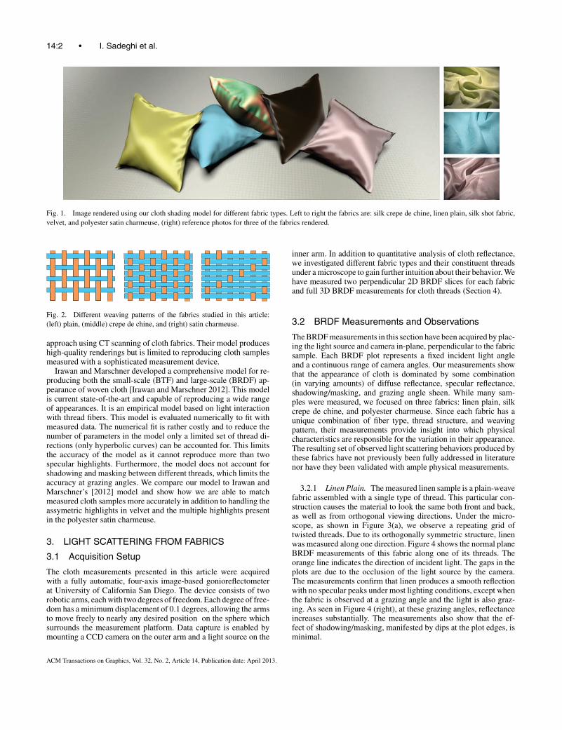
In this article we present a practical appearance model for cloth.Our model is based on extensive measurements of light scatteringby cloth samples and individual threads. Based on these measure-ments, we have developed a robust empirical shading model forwoven cloth based on light scattering from individual threads. Ourappearance model simulates distant viewing of cloth and ignoresthe appearance of individual threads unlike recent work on fab-rics [Irawan and Marschner 2012]. Our model takes into accountshadowing and masking that occurs between neighboring threads. Itis easy to control and can reproduce a wide range of fabrics includ-ing those made of linen, silk, polyester, and velvet (see Figure 1).We provide measured parameters for these cloth types including theweave definitions for our cloth samples (Figure 2).
The main advantage of our model is that it takes intuitive parame-ters that are fabric specific. The parameters are derived from nakedeye observation of the weave pattern, as well as the constrainedparametric space of our analytical thread scattering function. Thisenables the model to describe fabric BRDFs with or without mea-surements of a real cloth sample. Unlike a general microfacet model,which abstracts surface microstructure as a distribution of normals,our model allows for explicit control of the color and shininess ofindividual threads and precise definition of the weave structure.
2. PREVIOUS WORK
Rendering cloth has been an active area of research for more than25 years. The earliest approaches as well as more recent work arebased on simple empirical shading models [Weil 1986; Daubertet al. 2001; Glumac and Doepp 2004], where the primary goal isto achieve believable shading rather than physical accuracy. Micro-facet models have been used by Ashikhmin et al. to model satinand velvet [Ashikhmin et al. 2000]. Adabala et al. continued thiswork by including support for weave patterns [Adabala et al. 2003].Wang et al. [2008] introduced their own microfacet-based BRDFfor modeling spatially varying anisotropic reflectance using datacaptured from a single view. While microfacet models can be effec-tive at capturing a complex appearance, these models are difficultto control as they depend strongly on the right normal distributionfunction. Since cloth is often anisotropic, it is difficult to obtain thisdistribution from measured data (see Section 7).
Another approach for simulating cloth is based on modeling thestructure of the cloth [Xu et al. 2001; Chen et al. 2003; Dragoand Chiba 2004; Schroder et al. 2011]. While these methods canreproduce a wide range of appearances they can be difficult tocontrol. Yasuda et al. [1992] modeled the gloss seen in cloth byaccounting for the internal structure, but assumed a highly simpli-fied model of the cloth surface and the results lacked verification.Westin et al. [1992] computed BRDFs for velvet and plain-weavenylon fabrics by ray tracing a geometric model of the small-scalecloth structure. Zhao et al. [2011] presented a volumetric rendering
ACM Transactions on Graphics, Vol. 32, No. 2, Article 14, Publication date: April 2013.
14:2 • I. Sadeghi et al.
Fig. 1. Image rendered using our cloth shading model for different fabric types. Left to right the fabrics are: silk crepe de chine, linen plain, silk shot fabric,velvet, and polyester satin charmeuse, (right) reference photos for three of the fabrics rendered.
Fig. 2. Different weaving patterns of the fabrics studied in this article:(left) plain, (middle) crepe de chine, and (right) satin charmeuse.
approach using CT scanning of cloth fabrics. Their model produceshigh-quality renderings but is limited to reproducing cloth samplesmeasured with a sophisticated measurement device.
Irawan and Marschner developed a comprehensive model for re-producing both the small-scale (BTF) and large-scale (BRDF) ap-pearance of woven cloth [Irawan and Marschner 2012]. This modelis current state-of-the-art and capable of reproducing a wide rangeof appearances. It is an empirical model based on light interactionwith thread fibers. This model is evaluated numerically to fit withmeasured data. The numerical fit is rather costly and to reduce thenumber of parameters in the model only a limited set of thread di-rections (only hyperbolic curves) can be accounted for. This limitsthe accuracy of the model as it cannot reproduce more than twospecular highlights. Furthermore, the model does not account forshadowing and masking between different threads, which limits theaccuracy at grazing angles. We compare our model to Irawan andMarschner’s [2012] model and show how we are able to matchmeasured cloth samples more accurately in addition to handling theassymetric highlights in velvet and the multiple highlights presentin the polyester satin charmeuse.
3. LIGHT SCATTERING FROM FABRICS
3.1 Acquisition Setup
The cloth measurements presented in this article were acquiredwith a fully automatic, four-axis image-based gonioreflectometerat University of California San Diego. The device consists of tworobotic arms, each with two degrees of freedom. Each degree of free-dom has a minimum displacement of 0.1 degrees, allowing the armsto move freely to nearly any desired position on the sphere whichsurrounds the measurement platform. Data capture is enabled bymounting a CCD camera on the outer arm and a light source on the
inner arm. In addition to quantitative analysis of cloth reflectance,we investigated different fabric types and their constituent threadsunder a microscope to gain further intuition about their behavior. Wehave measured two perpendicular 2D BRDF slices for each fabricand full 3D BRDF measurements for cloth threads (Section 4).
3.2 BRDF Measurements and Observations
The BRDF measurements in this section have been acquired by plac-ing the light source and camera in-plane, perpendicular to the fabricsample. Each BRDF plot represents a fixed incident light angleand a continuous range of camera angles. Our measurements showthat the appearance of cloth is dominated by some combination(in varying amounts) of diffuse reflectance, specular reflectance,shadowing/masking, and grazing angle sheen. While many sam-ples were measured, we focused on three fabrics: linen plain, silkcrepe de chine, and polyester charmeuse. Since each fabric has aunique combination of fiber type, thread structure, and weavingpattern, their measurements provide insight into which physicalcharacteristics are responsible for the variation in their appearance.The resulting set of observed light scattering behaviors produced bythese fabrics have not previously been fully addressed in literaturenor have they been validated with ample physical measurements.
3.2.1 Linen Plain. The measured linen sample is a plain-weavefabric assembled with a single type of thread. This particular con-struction causes the material to look the same both front and back,as well as from orthogonal viewing directions. Under the micro-scope, as shown in Figure 3(a), we observe a repeating grid oftwisted threads. Due to its orthogonally symmetric structure, linenwas measured along one direction. Figure 4 shows the normal planeBRDF measurements of this fabric along one of its threads. Theorange line indicates the direction of incident light. The gaps in theplots are due to the occlusion of the light source by the camera.The measurements confirm that linen produces a smooth reflectionwith no specular peaks under most lighting conditions, except whenthe fabric is observed at a grazing angle and the light is also graz-ing. As seen in Figure 4 (right), at these grazing angles, reflectanceincreases substantially. The measurements also show that the ef-fect of shadowing/masking, manifested by dips at the plot edges, isminimal.
ACM Transactions on Graphics, Vol. 32, No. 2, Article 14, Publication date: April 2013.

A Practical Microcylinder Appearance Model for Cloth Rendering • 14:3
(a) linen plain (b) silk crepe de chine (c) polyester satin charmeuse
Fig. 3. Close-ups taken with a microscope of different fabrics and threads.
Fig. 4. BRDF measurements for linen plain for 0o, 30o, and 60o incidentangles.
Fig. 5. BRDF measurements for silk crepe de chine for 0o, 30o, and 60o
incident angles. The top row corresponds to the in-plane measurementsparallel to the direction of flat threads, and the bottom row represents themeasurements in the perpendicular direction.
3.2.2 Silk Crepe de Chine. The measured silk crepe dechine sample is assembled with two different types of threads(Figure 3(b)). The first type of thread is made of densely twistedfibers. This thread remains straight and uniformly spaced in thefabric. The second type of thread is made of thin and untwistedfibers, and passes above and below the first type. This thread ex-hibits sharp surface reflection and very little absorption resultingin its translucent appearance. While moving a light around the mi-croscope, a strong specular reflection in two incidence directions isvisible. The variation in thread type as well as the weaving patternstructure result in an asymmetrical surface which causes this fabricto appear significantly different depending on viewing direction.To study this, we measured the fabric BRDF along two orthogonaldirections (Figure 5). Measurements in the plane parallel to the flatthreads (top row) show two off-specular peaks, while the perpendic-ular plane measurements (bottom row) exhibit two grazing anglepeaks. Furthermore, the parallel measurements clearly indicate adrop in reflectance as the eye approaches grazing angle, suggestingthe contribution of shadowing/masking. In contrast, the perpen-dicular measurements maintain the grazing angle peaks under alllighting conditions.
Fig. 6. BRDF measurements for polyester charmeuse for 0o, 30o, and 60o
incident angles. Top row corresponds to in-plane measurements along thedirection of flat threads, and the bottom row represents measurements in theperpendicular direction.
3.2.3 Polyester Satin Charmeuse. The measured polyestersatin charmeuse sample is a satin-weave fabric, meaning that thethreads in one direction cross over most of the threads in the otherdirection. Like silk, this fabric is made out of two distinct (polyester)threads. The flat threads go above and below the twisted threads, butremain longer above than below. This asymmetry in the weavingpattern causes the fabric to have two different sides (Figure 3(c)).While moving the light around the microscope, we noticed strongreflections in three different directions of light. The variation inthread type and the asymmetric weaving pattern result in stronganisotropic scattering. The fabric was measured in two perpendic-ular planes (Figure 6). In-plane measurements along the directionof flat threads exhibit three specular peaks, one in the reflectiondirection and the other two in equal but opposite off-specular di-rections. Measurements in the perpendicular plane exhibit grazingangle peaks which are visible under all lighting conditions.
4. LIGHT SCATTERING FROM THREADS
In the previous section we noted that there are two different types ofthreads that contribute to the overall appearance of fabrics. The firstand most common type of threads are densely twisted threads. Thesethreads have many varieties that differ by twist level and constituentfiber count. The twist level of threads affects the compactness anddensity of fibers that compose them [Saville 1999]. The second typeof threads have a minimal amount of twist in their construction andwe refer to them as flat threads. These are usually less dense andhave a greater diameter due to their loosely packed structure. Boththread categories are fed by a diverse selection of raw materialssuch as silk, cotton, wool, flax, and synthetic filaments. We furtherinvestigate the light scattering properties of cloth by measuring theBSDF of different types of threads.
ACM Transactions on Graphics, Vol. 32, No. 2, Article 14, Publication date: April 2013.

14:4 • I. Sadeghi et al.
Fig. 7. The gantry setup used to measure the BSDF of threads. The threadis suspended vertically, which makes it possible to capture the full 4D BSDF.
4.1 Acquisition Setup
We measured the scattered radiance distribution of several threadtypes using the same spherical gantry as used for the clothmeasurements and a unique suspension apparatus. The results serveto validate our analytical model as well as provide a qualitativebasis for reasoning about threads and cloth in general. In ourmeasurements we illuminate an 8cm section of thread with acollimated light beam and collect radiance scattering measurementswith a CCD camera.
To procure a thread sample, we first remove a single strand froma finished fabric. When a thread is removed from fabric it is nolonger straight, but retains the shape that it had in the fabric. Inorder to obtain accurate scattering measurements, the thread mustbe extended to its maximal length. This type of procedure is commonin fabric quality testing and requires standard tension, which has thegeneral goal of nondestructively pulling on one end of the thread.In our experimental thread mount, we clamp one end of the threadto a poseable arm, and let the rest of it hang, weighed down by amagnatized set of spheres at the unclamped end. Hanging the threadin mid-air allows the gantry to measure a full 4D BSDF with minimalocclusions and no background to contaminate the measurements(see Figure 7). Additionally, gravity provides a consistent verticallyaligned axis, which eliminates the need for pose calibration.
4.2 BSDF Measurements
We measured a 3D BSDF by varying the longitudinal angles θi ,θr , and the azimuthal difference angle φd = φi − φr . Figure 9shows the notations used in our article. We did not measure a 4DBSDF because we assumed symmetry of the BSDF with respectto φ. Since threads are not perfect cylinders, this assumption issomewhat violated, however, it allows us to capture less data whilestill observing the salient thread scattering features. We present aplanar slice of the resulting measurements in Figure 8. Here theBSDF is a function of two angles (θi and θr ). We present severalθi angles and plot a continuous range of BSDF measurements forθr . The threads were not treated with any dyes and no polarizingfilters were used. As a result, the BSDF plots represent the naturallyvisible combination of surface reflection and internal scattering.To facilitate intuition about the plots we can state the following:surface reflection results in a lobe in the specular reflection direction(θr = −θi), and internal scattering results in a wider lobe that ismore decoupled from appearing in the specular direction. The toprow of Figure 8 demonstrates the similarity among flat threadsand their disparity from twisted threads. In the top row, both the
Fig. 8. Polar plots of measured incidence plane BSDF for different threads.Each quadrant of the figure contains the RGB average BSDF for a threadtype. Starting at the top row, and moving left to right we have flat silk thread,flat polyester thread, twisted linen thread, and twisted silk thread.
Fig. 9. Notations and geometry of light reflection from a cylindrical fiber.Longitudinal angles θ are computed with respect to the normal plane andthe azimuthal angles φ are computed based on the local surface normaldirection n. When the thread is not part of a fabric, n can be any arbitrarydirection within the normal plane.
polyester and the silk thread possess narrow specular lobes orientedat the exact specular reflection direction. This result can be attributedto their low surface roughness as well as minimal internal scattering.The fact that the lobe is oriented at the exact specular reflectiondirection means that, unlike hair, threads have no consistent cuticlethat displaces their specular reflection. The polyester thread is themore specular of the two flat threads, as evidenced by its narrowerand brighter reflection lobe. This can be attributed to the syntheticversus organic fibers that they are composed of, where polyester hasfewer natural imperfections and irregularities due to its industrialfabrication process.
At first glance the twisted threads in the bottom row of Figure 8appear nearly identical. They both exhibit a characteristic widescattering lobe that slowly increases as the light goes to glancingangle. Focusing on glancing incidence angles, we observe that thetwisted linen thread scatters more light in the nonspecular directions.This type of scattering can be attributed to either a very roughsurface or isotropic internal scattering. We address these behaviorsin subsequent sections when we present our thread BSDF model.
ACM Transactions on Graphics, Vol. 32, No. 2, Article 14, Publication date: April 2013.

A Practical Microcylinder Appearance Model for Cloth Rendering • 14:5
Table I. Description of Important Symbolsfs Thread scattering functionFr Fresnel reflectanceFt Fresnel transmittanceγs Surface reflectance Gaussian widthγv Volume scattering Gaussian widthkd Isotropic scattering coefficientA Colored albedo coefficient
4.3 A Light Scattering Model for Threads
Based on our measurements of individual threads, we observed anoptical behavior that is similar to hair and, more generally, smoothdielectric cylinders. We observed that the reflection of a collimatedlight beam from a taut thread sample forms a cone centered onthe thread axis. Additionally, the surface reflection is framed by asubtle color reflection that is also centered at the cone. This type ofreflection from cylinders has been previously studied by Kajiya andKay [1989], Kim [2002], and Marschner et al. [2003], where thenormal plane around the tangent is used as the coordinate frame forcomputing light scattering behavior. Unlike hair, threads do not haveconsistent tilted cuticles on their surface and therefore the reflectedrays are distributed around the reflection cone. In our model weuse the cylinder abstraction to represent a thread. When an incidentbeam from ωi consisting of parallel rays of light strikes a threadcylinder running along the vector t , each ray in the beam reflects atthe surface according to the surface normal of the cylinder. Thesesurface normals are all perpendicular to the thread tangent vectort and lie in the normal plane. For a smooth specular cylinder, abeam incident at θi will be reflected in the ideal specular direction−θi across the normal plane and, due to the circular cross-sectionof the cylinder, will be spread into a cone [Kajiya and Kay 1989].The refracted light will enter the cylinder and after any number ofinternal reflections and refraction will emit into the same cone asthe surface specular reflection [Marschner et al. 2003].
To establish radiometric notation for our cylinder-based modelwe use the curve radiance integral from Marschner et al. [2003].
Lr =∫
fs(t, ωi, ωr )Li(ωi) cos θi dωi (1)
Note that unlike the standard radiance integral on a surface, thereflected radiance from a cylinder differs by the fact that it is definedover a unit length instead of a unit area. This difference arises fromthe fact that the cylinder scattering function accounts for all the lightscattered around the circumference of the cylinder.
As in previous treatments of BSDFs [Hanrahan and Krueger1993], we separate our scattering function fs(t, ωi, ωr ) into a sur-face scattering component fr,s , and volume scattering componentfr,v . In addition to the angles in Figure 9, we introduce φd = φi −φr ,θh = (θi + θr )/2, and θd = (θi − θr )/2 to define the two scatteringfunctions.
4.3.1 Surface Reflection. We model surface reflection similarlyto Marschner et al. [2003], except we do not decompose our com-putation into longitudinal and azimuthal planes.
fr,s(t, ωi, ωr ) = Fr (η, �wi) cos(φd/2)g(γs, θh) (2)
The cos(φd/2) term arises due to projection of the circular cylindercross-section, as demonstrated by Kim [2002], and previously usedby Sadeghi et al. [2010] for hair rendering. To break away fromthe idealized smooth cylinder representation of threads, we employa unit area Gaussian g with width γs to simulate surface roughness.
Finally, we add a physical basis to the model by attenuating thepower by a Fresnel term. The angle used to compute the Fresnelterm is based on the reflection normal on the cylinder as well asa half-angle between the light and the eye, yielding an exact ex-pression Fr (η, cos−1(cos(θd ) cos(φd/2))). Here, θd comes from theeffective angle between our incident light and the ideally orientedfacet to result in a reflection toward the view direction. The φd anglearises from the fact that we are modeling a cylinder and the ideal re-flection between the light and the view direction is also dependenton the azimuthal difference angle. This model produces a glossyreflection on a cone around the thread with physical and geomet-ric attenuation. We considered using the full micro-facet specularformulation, but found that it did not improve the matching to ourmeasured results.
4.3.2 Volume Scattering. Real threads are composed of fibersthat are either twisted together or lay flat next to each other. Wemake a unifying assumption that all fiber types are cylindrical withminimal eccentricity. This is generally true with the exception ofcotton, which resembles a flat ribbon. To summarize, our model isa large thread cylinder composed of tiny fiber subcylinders. Thisenables us to use the fact that smooth cylinders emit light dueto surface and internal scattering into the ideal reflection cone.Therefore, light that enters the thread volume and undergoes anytype of scattering interaction with the fiber subcylinders will result ina surface emission distributed around the same cone as the surfacereflection. This scattering property is very important because itimplies that internal scattering can be anisotropic. From our threadBSDF measurements, we found that grazing angle illumination ofthreads produced varying degrees of colored forward scattering.One thing to note is that the orientation of the fiber subcylindersdeviates from that of the thread cylinder. We model this deviationas a Gaussian distribution centered on the thread tangent.
fr,v(t, ωi, ωr ) = F(1 − kd ) g(γv, θh) + kd
cos θi + cos θr
A (3)
Here F = Ft (η, �wi)Ft (η′, �w′r ) is the product of two transmission
Fresnel terms. We define the subcylinder tangent deviation witha Gaussian lobe g with width γv . The Gaussian lobe controls thewidth of the forward scattering cone. For twisted threads, whichconsist of fibers that deviate from the thread tangent direction, thisGaussian is wider than for flat threads which mainly consist ofparallel filaments. Additionally, we define a tunable isotropic scat-tering term kd and a color albedo term A. We added an isotropicscattering term to account for cellulose-based fibers such as cottonand linen, which predominantly yield isotropic volume scatteringinstead of a forward scattering cone. The division by the sum of pro-jected cosines comes from Chandrasekhar [1960], in his derivationfor diffuse reflectance due to multiple scattering in a semi-infinitemedium. Adding this normalization term gave us better matcheswith our measured results. The complete thread scattering model isa sum of the surface and volume components.
fs(t, ωi, ωr ) = (fr,s(t, ωi, ωr ) + fr,v(t, ωi, ωr )
)/ cos2 θd (4)
Note that the complete scattering formulation contains a divisionby cos2θd , which is necessary to account for the solid angle at-tenuation of the specular cone [Marschner et al. 2003]. Previouswork has addressed volume scattering in threads with a cylindri-cal phase function in Irawan and Marschner [2012] as well as theHenyey-Greenstein phase function in Adabala et al. [2003]. We ex-perimented with various phase functions as well, but found theminadequate due to their decoupled behavior from the direction ofthe thread. Our approach is similar in spirit to Jakob et al. [2010],
ACM Transactions on Graphics, Vol. 32, No. 2, Article 14, Publication date: April 2013.
14:6 • I. Sadeghi et al.
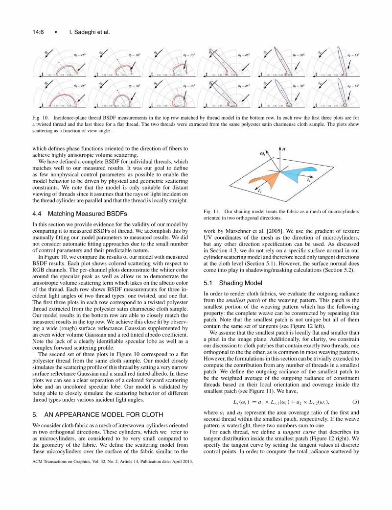
Fig. 10. Incidence-plane thread BSDF measurements in the top row matched by thread model in the bottom row. In each row the first three plots are fora twisted thread and the last three for a flat thread. The two threads were extracted from the same polyester satin charmeuse cloth sample. The plots showscattering as a function of view angle.
which defines phase functions oriented to the direction of fibers toachieve highly anisotropic volume scattering.
We have defined a complete BSDF for individual threads, whichmatches well to our measured results. It was our goal to defineas few nonphysical control parameters as possible to enable themodel behavior to be driven by physical and geometric scatteringconstraints. We note that the model is only suitable for distantviewing of threads since it assumes that the rays of light incident onthe thread cylinder are parallel and that the thread is locally straight.
4.4 Matching Measured BSDFs
In this section we provide evidence for the validity of our model bycomparing it to measured BSDFs of thread. We accomplish this bymanually fitting our model parameters to measured results. We didnot consider automatic fitting approaches due to the small numberof control parameters and their predictable nature.
In Figure 10, we compare the results of our model with measuredBSDF results. Each plot shows colored scattering with respect toRGB channels. The per-channel plots demonstrate the whiter coloraround the specular peak as well as allow us to demonstrate theanisotropic volume scattering term which takes on the albedo colorof the thread. Each row shows BSDF measurements for three in-cident light angles of two thread types: one twisted, and one flat.The first three plots in each row correspond to a twisted polyesterthread extracted from the polyester satin charmeuse cloth sample.Our model results in the bottom row are able to closely match themeasured results in the top row. We achieve this close fit by observ-ing a wide (rough) surface reflectance Gaussian supplemented byan even wider volume Gaussian and a red tinted albedo coefficient.Note the lack of a clearly identifiable specular lobe as well as acomplex forward scattering profile.
The second set of three plots in Figure 10 correspond to a flatpolyester thread from the same cloth sample. Our model closelysimulates the scattering profile of this thread by setting a very narrowsurface reflectance Gaussian and a small red tinted albedo. In theseplots we can see a clear separation of a colored forward scatteringlobe and an uncolored specular lobe. Our model is validated bybeing able to closely simulate the scattering behavior of differentthread types under various incident light angles.
5. AN APPEARANCE MODEL FOR CLOTH
We consider cloth fabric as a mesh of interwoven cylinders orientedin two orthogonal directions. These cylinders, which we refer toas microcylinders, are considered to be very small compared tothe geometry of the fabric. We define the scattering model fromthese microcylinders over the surface of the fabric similar to the
Fig. 11. Our shading model treats the fabric as a mesh of microcylindersoriented in two orthogonal directions.
work by Marschner et al. [2005]. We use the gradient of textureUV coordinates of the mesh as the direction of microcylinders,but any other direction specification can be used. As discussedin Section 4.3, we do not rely on a specific surface normal in ourcylinder scattering model and therefore need only tangent directionsat the cloth level (Section 5.1). However, the surface normal doescome into play in shadowing/masking calculations (Section 5.2).
5.1 Shading Model
In order to render cloth fabrics, we evaluate the outgoing radiancefrom the smallest patch of the weaving pattern. This patch is thesmallest portion of the weaving pattern which has the followingproperty: the complete weave can be constructed by repeating thispatch. Note that the smallest patch is not unique but all of themcontain the same set of tangents (see Figure 12 left).
We assume that the smallest patch is locally flat and smaller thana pixel in the image plane. Additionally, for clarity, we constrainour discussion to cloth patches that contain exactly two threads, oneorthogonal to the the other, as is common in most weaving patterns.However, the formulations in this section can be trivially extended tocompute the contribution from any number of threads in a smallestpatch. We define the outgoing radiance of the smallest patch tobe the weighted average of the outgoing radiance of constituentthreads based on their local orientation and coverage inside thesmallest patch (see Figure 11). We have,
Lr (ωr ) = a1 × Lr,1(ωr ) + a2 × Lr,2(ωr ), (5)
where a1 and a2 represent the area coverage ratio of the first andsecond thread within the smallest patch, respectively. If the weavepattern is watertight, these two numbers sum to one.
For each thread, we define a tangent curve that describes itstangent distribution inside the smallest patch (Figure 12 right). Wespecify the tangent curve by setting the tangent values at discretecontrol points. In order to compute the total radiance scattered by
ACM Transactions on Graphics, Vol. 32, No. 2, Article 14, Publication date: April 2013.

A Practical Microcylinder Appearance Model for Cloth Rendering • 14:7
Fig. 12. The weaving pattern and a sample tangent curve for the polyestersatin charmeuse fabric: (left top) the weaving pattern, (left bottom) a smallestpatch, (right) the tangent curve for the two types of threads. The red arrowsindicate the local normal of the tangent.
each thread, we sample its corresponding tangent curve and evaluatethe thread BRDF for each tangent direction j as
Lr,j (ωr ) = 1
Nj
∑t
∫Li(ωi)fs(t, ωi, ωr ) cos θi dωi, (6)
where Nj is the number of tangent samples and fs is the analyticalthread BSDF model introduced in Section 4.3.
5.2 Shadowing and Masking
Shadowing and masking are very important for the correct evalu-ation of the outgoing radiance, especially at grazing angle view-ing and lighting directions. Poulin and Fournier [1990] derived ashadowing and masking term for grooved surfaces composed ofcylinders. However, their approach is not applicable to our modelsince they assumed that the cylinders have a surface patch BRDFand integrated all of the reflected light scattered toward a viewer.Since our formulation treats cylinders as one-dimensional entities,we do not compute the explicit reflectance variation across theircircumference.
Shadowing and masking are very similar concepts; shadowingcan be thought of as masking from the point of view of the lightsource. We interchangeably refer to both of these quantities as mask-ing M in the rest of this section. We only compute the maskingbetween the same types of threads (i.e., threads with the same car-dinal directions). Shadowing between orthogonal threads is moreinvolved and is left as future work.
Consider the setup shown in Figure 13 where the fabric is wrappedaround a cylinder. Let us first focus on the horizontal threads only(Figure 13 middle). Threads along this direction never occlude eachother from the viewer even at grazing angles. Therefore, the cylin-der BSDF defined in Section 4.3 alone can be used to computethe correct outgoing radiance from these types of threads with nomasking adjustment.
Now let us consider the vertical threads (Figure 13 right). Atgrazing angles each thread partially masks the thread behind it andgets masked by the thread in front of it. The amount of masking isrelative to the cosine of the viewing direction projected to the threadnormal plane and the surface normal. This angle is equal to φr (seeFigure 9).
M(t, ωr ) = max(cos φr, 0) (7)
If the cosine is negative, the surface is backfacing and is being self-masked. The same argument holds for the light direction and resultsin shadowing.
M(t, ωi) = max(cos φi, 0) (8)
Here φi and φr are computed with respect to the local normal ofthe tangent t . If the tangent deviates from the surface tangent by α
Fig. 13. Fabric as two different directions of threads with views from above(green arrows) and from grazing angles (red arrows): (left) The contributionof different threads in the smallest patch is related to the orientation of thepatch. At grazing angles, the blue thread contributes less than the orangethread. (middle) In the longitudinal direction, there is no masking and noadjustment needed. (right) In the azimuthal direction, the amount of maskingin grazing angles is dependent on the cos φr .
degrees then its normal will deviate from the surface normal by αdegrees as well. See Figure 12 for an illustration.
When ωi and ωr are not correlated, the overall shadowing andmasking amount is equal to the multiplication of M(t, ωi) andM(t, ωr ). In cases where these two directions are close to eachother, we use the adjustment introduced by Ashikhmin et al. [2000]to compute the overall shadowing and masking term M(t, ωi, ωr )
M(t, ωi, ωr ) = (1 − u(φd )) M(t, ωi) × M(t, ωr )
+ u(φd ) min(M(t, ωi), M(t, ωr )), (9)
where u is a unit height Gaussian function with standard deviationbetween 15o and 25o [Ashikhmin et al. 2000]. We will refer toM(t, ωi, ωr ) in short as M(t).
We can rewrite Eq. (6) to include the effect of shadowing andmasking.
Lr,j (ωr ) = 1
Nj
∑t
∫Li(ωi)fs(t, ωi, ωr )M(t) cos θi dωi (10)
To see the effect of shadowing and masking see Figure 15. Notethe bright edges in the vertical mode which are the results of thecontribution of all vertical flat fibers at grazing angles. The maskingterm corrects this effect by reducing the intensity of masked threadsat grazing angles.
5.3 Reweighting
So far we have considered that the contribution of a thread to theoverall reflection of the smallest patch is based on its length (i.e.,area coverage). This is only correct when the ωr and ωi are nearsurface normal n. We need to adjust the contribution of each threadtangent t based on its projected length P (t, ωi) in the directionof the viewer. Tangents that are more visible inside the smallestpatch will have a higher contribution (for that viewing angle). Werefer to this adjustment as reweighting. This process determinesthe contribution of each thread tangent curve sample to the overallreflectance of the smallest patch.
Projection of the tangents onto the viewing direction is based onthe cosine of the longitudinal angle ψr . As shown in Figure 14, ψr
is the angle between local surface normal n and the projection of
ACM Transactions on Graphics, Vol. 32, No. 2, Article 14, Publication date: April 2013.

14:8 • I. Sadeghi et al.
Fig. 14. Longitudinal angles ψi and ψr are the angles between local surfacenormal n and the projection of ωi and ωr on to the plane spanned by the t
and n vectors.
ωr on to the plane that contains t and n.
P (t, ωr ) = max(cos ψr, 0) (11)
When the cosine is negative, the tangent is being self-maskedand contributes zero to the overall reflection of the patch. Similarto the masking term, we calculate the projection for both ωi and ωr
directions.
P (t, ωi) = max(cos ψi, 0) (12)
This means that tangents receive energy based on their visibilityfrom the point of view of the light source. We combine these twoprojections to get the final projection term P (t, ωi, ωr )
P (t, ωi, ωr ) = (1 − u(ψd )) P (t, ωi) × P (t, ωr )
+ u(ψd ) min(P (t, ωi), P (t, ωr )), (13)
where ψd is the difference between ψi and ψr . We refer toP (t, ωi, ωr ) in short as P (t). Finally we can rewrite Eq. (10) andput it in Eq. (5) to get the final outgoing radiance of the smallestpatch.
Lr,j (ωr ) = 1
Q
1
Nj
∑t
∫Li(ωi)fs(t, ωi, ωr )M(t)P (t) cos θi dωi
(14)
Here Q is a normalization factor computed as
Q = a1
N1
∑t
P (t) + a2
N2
∑t
P (t) + (1 − a1 − a2)(ωr · n), (15)
where N1 and N2 are the number of samples of each thread direction,and n is the surface normal of the fabric. The last component in thisequation accounts for the projected area of the gaps in the casethe threads do not cover the patch completely (e.g., the linen plainfabric) and a1 + a2 < 1. The reweighting adjustment in Eq. (14)reduces the contribution of foreshortened threads in the smallestpatch which is especially important for grazing angles. The effectof reweighting on the final result is demonstrated in Figure 15.In the vertical mode, the flat threads contribute more to the finalradiance than the twisted threads since they occupy more area ofthe projected smallest patch.
6. RESULTS
We have implemented the cloth model in a ray tracer and on theGPU. This section contains rendered results for several differentcloth fabrics. The parameters for each cloth sample are summarizedin Table II.
Fig. 15. The effect of shadowing and masking and the reweighting processon the final results: (a) the result for the shading model; (b) the effect ofshadowing/masking term; (c) the final results after applying shadowing/masking and reweighting.
We validate our cloth model by comparing rendered results tophotographs. To capture the anisotropic behavior of different fab-rics, we wrapped the fabrics around a cylinder in three differentdirections. We label each mode based on the orientation of the flatthreads as vertical, horizontal, and diagonal (see Figure 16). For thelinen plain fabric, the vertical and horizontal modes are identical.For comparison, we present our rendered results of different fabricsin the same setup. Figure 17 shows linen plain fabric. The top rowimages are the photographs of the fabric and the bottom row imagesare rendered using our model. The graphs show the average valuesof the pixels on the y-axis. This fabric shows similar behavior onthe vertical and horizontal mode due to the symmetry of the plain-weaving pattern. However, it has a different appearance when thesample is rotated 45 degrees in the diagonal mode, which demon-strates the subtle anisotropic behavior of this fabric. Our renderingsqualitatively match the photographs in all three cases.
Figure 18 shows the results for the silk crepe de chine fabric.This fabric has grazing angle highlights in the vertical mode andshows two off-specular highlights in the horizontal mode. The twooff-specular peaks are due to the two constant slope segments insidethe tangent distribution of the flat threads (shown in blue). Thesebehaviors can be seen in the BRDF measurements of this fabricas well (see Figure 5). However, it is important to note that theseplots are essentially different; in the BRDF measurements, the ωi
and surface normal n are fixed and the ωr is changing, while inthese graphs the ωi and ωr are fixed and n is changing. Our modelcan successfully capture the light scattering behavior of this fabricunder all three orientations.
The photograph and the renderings for the front side of polyestersatin charmeuse fabric are shown in Figure 19. The back side ofthis fabric shown in Figure 20 has a different appearance due tothe asymmetry of the weaving pattern. On the front side, the fabrichas a flat appearance in the vertical mode and presents three sharpspecular highlights in the horizontal mode. These three highlightsare due to the three constant slope segments inside the tangentdistribution of the flat threads (shown in blue) in the weaving pattern.On the back side, we can see four highlights in the horizontal mode.Our renderings reproduce the appearance of this fabric for both sidesand for all three orientations with the same parameters. Figure 21shows a comparison of our model BRDF with the measured BRDFof the fabric (Figure 21 top) for the front side of the fabric andalong the direction of flat threads. Note how our model is able tocapture the variation in the location of the highlights and the overallshape of the reflected light as the light source moves from normalincidence to 30 and 60 degrees.
Figure 22 demonstrates how our model can reproduce the ap-pearance of other fabrics that have been previously studied. Wehave successfully matched a silk shot fabric presented in Pontand Koenderink [2003] (Figure 22) and a velvet fabric presentedin Ashikhmin [2001] (Figure 23). The silk shot fabric is composed ofthreads with two different colors (in this case red and green) result-ing in a complex anisotropic appearance. Our model can reproduce
ACM Transactions on Graphics, Vol. 32, No. 2, Article 14, Publication date: April 2013.

A Practical Microcylinder Appearance Model for Cloth Rendering • 14:9
Table II. The List of Parameters Obtained from Our Measured Cloth Samplesη Thread A kd γs γv a Tangent Offsets (degrees) Tangents Lenghts
(a) 1.46 Both (0.2, 0.8, 1) × 0.3 0.3 12 24 0.33 -25, 25 1
(b) 1.345 Flat (1, 0.95, 0.05) × 0.12 0.2 5 10 0.75 -35, -35, 35, 35 1, 1, 1Twisted (1, 0.95, 0.05) × 0.16 0.3 18 32 0.25 0, 0 1
(c) 1.539 Flat (1, 0.37, 0.3) × 0.035 0.1 2.5 5 0.9 -32, -32, -18, 0, 0, 18, 32, 32 1.33, 0.66, 2, 2, 2, 0.66, 1.33Twisted (1, 0.37, 0.3) × 0.2 0.7 30 60 0.1 0, 0 1
(d) 1.539 Flat (1, 0.37, 0.3) × 0.035 0.1 2.5 5 0.67 -30, -30, 30, 30, -5, -5, 5, 5 1.33, 1.33, 1.33, 0, 0.67, 0.67, 0.67Twisted (1, 0.37, 0.3) × 0.2 0.7 30 60 0.33 0, 0 3
(e) 1.345 Dir 1 (0.1, 1, 0.4) × 0.2 0.1 4 8 0.86 -25, -25, 25, 25 1.33, 2.67, 1.33Dir 2 (1, 0, 0.1) × 0.6 0.1 5 10 0.14 0, 0 1
(f) 1.46 Dir 1 (0.05, 0.02, 0) × 0.3 0.1 6 12 0.5 -90, -50 1Dir 2 (0.05, 0.02, 0) × 0.3 0.1 6 12 0.5 -90, -55, 55, 90 0.5, 0, 0.5
The γ parameters are measured in degrees.
Fig. 16. To capture the anisotropic behavior of different fabrics, we havewrapped the fabric around a cylinder in three different orientations wherethe flat threads stay (left) vertical, (middle) horizontal, and (c) diagonal.
Fig. 17. Photographs (top row) and the rendered results (bottom row) of the linen plain fabric. Thread tangent curves for thewarp and weft are pictured at (right).
this appearance using anisotropic volume scattering by the col-ored threads rather than the shadowing and masking effect as itwas assumed by Pont and Koenderink [2003]. Figure 23 showshow asymmetric highlights of velvet can be reproduced by settingthe tangent curves to be near perpendicular to the surface of thefabric.
Figure 24 shows a variety of fabrics rendered using our model. Inthis image we are using a texture map to specify the groom directionfor the velvet fabric. We also included two imaginary fabrics: oneis a weaving of silk and polyester threads using a shantung weavingpattern and the other is using an imaginary fabric with asymmetricspecular peaks.
In order to reproduce the appearance of new fabrics, users cantake advantage of our thread BSDF parameters as a starting pointwithout the need for any measurements. We have presented severalBSDFs for common thread types which establish parametric con-
Fig. 18. Photographs (top row) and the rendered results (bot-tom row) of the silk crepe de chine fabric. Thread tangent curves for the warp and weft are pictured at (right).
Fig. 19. Photographs (top row) and the ren-dered results (bottom row) of the front sideof polyester satin charmeuse fabric. Threadtangent curves for the warp and weft are pic-tured at (right).
straints for existing materials. By observing with the naked eye ora macrolens, one can approximate the weave pattern and define thetangent curves. Alternatively, one can guess the weaving structureand thread BSDF by investigating the overall cloth appearance (e.g.,from our cylinder setup).
6.1 Performance
The images in Figure 24 of a piece of cloth illuminated by an arealight have been rendered in 512 × 512 resolution with 144 samplesper pixel in an unoptimized CPU ray tracer. The renderings took51 minutes on average on an 2.83 GHz Intel Core 2 CPU.
ACM Transactions on Graphics, Vol. 32, No. 2, Article 14, Publication date: April 2013.

14:10 • I. Sadeghi et al.
Fig. 20. Photographs (top row) and the ren-dered results (bottom row) of the back sideof polyester satin charmeuse fabric. Threadtangent curves for the warp and weft are pic-tured at (right).
Fig. 21. Matching a BRDF measurement of the polyester satin charmeusefabric with our model. (top) normal-plane BRDF measurement of the frontside of polyester satin charmeuse fabric along the direction of flat threadscompared to (bottom) the result of our appearance model.
Fig. 22. Photographs (top row) and the renderedresults (bottom row) of a silk shot fabric(from Pont and Koenderink [2003]). Threadtangent curves for the warp and weft are pic-tured at (right).
We also implemented the full cloth model in a GPU shader. Theimages in Figure 25 are lit by a single directional light and wererendered in 100 ms for 1 sample per pixel on a laptop with anIntel I5 M480 processor and a mobile NVIDIA GT420 GPU. Thereis a host of performance optimizations available to our algorithmspecifically in the areas of precomputed lookup tables and tangentcurve sampling. We aim to address this in future work as we extendthe capabilities of our model.
7. DISCUSSION
As shown in the results, our model is able to reproduce the complexbehavior of a variety of fabrics. Our appearance model is based onan analytical thread BSDF and a tangent distribution to describea weaving pattern. Our work is similar to the model of Ashikhmin
Fig. 23. Photographs (top row) and the rendered results (bottomrow) for velvet fabric (from Ashikhmin [2001]). Note that ourmodel can successfully reproduce the asymmetric highlightsseen in the horizontal mode. Thread tangent curves are picturedat (right).
et al. [2000] since it can reproduce specular highlights in any di-rection. We accomplish this by orienting the thread tangents so thattheir reflection cone lies in the desired direction. The input of ourmodel is intuitively based on the weaving pattern of the fabric,while the microfacet model requires a complicated mathematicalrepresentation of the facet normals. For example, to produce the ap-pearance of velvet, Ashikhmin et al. propose c × exp(− cot2 θ/σ 2)as the normal distribution (where c and σ are control parameters).Formulating such an equation can be a challenging task. In ourmodel, we represent velvet by simply defining the thread tangentsto be nearly parallel to the surface normal.
State-of-the-art research in cloth rendering has been carried outby Irawan and Marschner [2012]. They present a rigorous modelfor computing light reflection off of yarn threads, which are sim-ulated as an assembly of specular fibers. The model incorporatescostly numerical integrations and a fitting process to estimate thevalue of different control parameters. We implemented the Irawanand Marschner cloth BRDF as a shader in PBRT for comparisonpurposes. Irawan and Marschner’s model is capable of reproducinga range of appearances including linen plain and silk crepe de chineas seen in Figure 26. Irawan and Marschner’s model can reproducethe appearance of linen plain fabric relatively well, but fails to re-produce the grazing angle highlights seen in the vertical mode ofthe silk crepe de chine fabric. One of the limitations of Irawan andMarschner’s model is that the curvature of the threads has to be ahyperbolic curve. This constraint is a core component of the Irawanand Marschner model because it simplifies the computation of thecomplex lighting integrals that are involved. Because of this limita-tion, Irawan and Marschner’s model can produce only one highlight(for large positive values of κ) or two very sharp highlights (forvalues of κ close to −1). Consequently, Irawan and Marschner’smodel cannot reproduce all the highlights seen in the polyestersatin charmeuse fabric (Figure 27). For both sides of this fabric,Irawan and Marschner’s model is unable to produce more than twohighlights. We present two sets of rendered images for each side,in order to match two of the highlights at a time. The symmetry ofhyperbolic curves also makes it impossible to reproduce the asym-metric highlights seen in the velvet fabric (see Figure 28). The silkshot fabric is also a challenge for Irawan and Marschner’s model.In order to match the measurement we had to multiply the specularcoefficient ks with different color values, which is physically incor-rect due to the fact that simple surface reflection maintains the colorof the incident light. Choosing two different kd colored values (redand green) resulted in a brown mixture of both colors in all threeorientations.
Additionally, hyperbolic curves cannot represent constant slopesegments and therefore the off-specular highlights in the Irawan andMarschner model are very sharp and narrow. To alleviate this prob-lem, Irawan and Marschner use a smoothstep function which softensoutside of the highlights, but also produces the undesired artifactof a sharp transition at the start of highlights (see the results forvelvet in Figure 28). The smoothstep function, aside from lacking a
ACM Transactions on Graphics, Vol. 32, No. 2, Article 14, Publication date: April 2013.

A Practical Microcylinder Appearance Model for Cloth Rendering • 14:11
Fig. 24. Our rendered results for different fabrics lit by a square area light. From top to bottom, left to right: linen plain, silk crepe de chine, front side ofpolyester satin charmeuse, back side of the polyester satin charmeuse, silk shot fabric, velvet, an imaginary fabric made out of silk and polyester threads witha shantung weaving pattern, and an imaginary fabric with asymmetric specular peaks.
Fig. 25. Screenshots from the GPU implementation of our model undersingle directional lighting. Each image was rendered in roughly 100 ms ona mobile GT420 GPU.
Fig. 26. Photographs (top row) and the rendered results (bottom row) usingIrawan and Marschner’s model for the (left) linen plain fabric and (right) silkcrepe de chine fabric. Note that this model is unable to reproduce grazingangle highlights seen in the vertical mode in the silk crepe de chine fabric.
physical basis, also alters the position of the highlights and makesthe model less predictable. Finally, Irawan and Marschner’s modeldoes not account for shadowing and masking between threads. Wehave summarized all of the parameters of the Irawan and Marschnermodel used for rendering different fabrics in the online appendix.
Fig. 27. Photographs (top row) and two rendered results (middle and bot-tom rows) by Irawan and Marschner’s model for the (left) front side and(right) back side of the polyester satin charmeuse fabric. Note that this modelcannot reproduce more than two highlights in all cases and fails to reproducethe correct appearance.
Fig. 28. Photograph (top row) and the rendered results (bottom row) usingIrawan and Marschner’s model for the (left) shot fabric and (right) velvet.In order to match the shot fabric we had to multiply the specular compo-nent with a color value. Also, note that this model fails to reproduce theasymmetric highlights of velvet.
A limitation of our model in its current form is that it cannot accu-rately produce close-up renderings. It does not reproduce the appear-ance of single threads in a patch, or the reflectance variation acrosseach thread. This limitation can be somewhat worked around with a
ACM Transactions on Graphics, Vol. 32, No. 2, Article 14, Publication date: April 2013.

14:12 • I. Sadeghi et al.
texture, but a texture will fail for extreme close-ups, where it will benecessary to model actual geometry such as Zhao et al. [2011]. Addi-tionally, our shadowing and masking term does not handle maskingbetween threads in orthogonal directions. This causes an underes-timation of masking at extreme grazing angles. Finally, our modelignores the effect of multiple scattering between different threads.
8. CONCLUSION AND FUTURE WORK
We have presented a practical appearance model for cloth fabrics.Our model is robust and easy to use, while being able to repro-duce the complex anisotropic appearance of cloth. We present bothmeasurements and a novel scattering model for threads. Our clothBRDF is based on the distribution of thread tangents, and it in-cludes shadowing and masking terms that are important for grazingangle viewing and lighting. Our results show that we can matchthe appearance of real fabrics including reproducing the complexanisotropic highlights and color shifts. We also demonstrate howprevious state-of-the-art models for cloth appearance fail to repro-duce important scattering phenomena that are common in fabrics.
One avenue for future research is investigating the shadowingand masking between threads with different directions. Addition-ally, we are interested in testing automated fitting processes to esti-mate the parameters of our model based on photographs of a fabricwrapped around a cylinder in different directions. Furthermore, weaim to investigate the transmission term and approximate the mul-tiple scattering of light between different threads. Lastly, it wouldbe interesting to investigate different ways of importance samplingour fabric BRDF.
ELECTRONIC APPENDIX
The electronic appendix is available in the ACM Digital Library.
ACKNOWLEDGMENTS
A special thanks goes to Marlena Fecho for the comparisons ofour results with Irawan and Marschner’s model. The Irawan andMarschner shader used in this article was based on a shader byYang [2009]. We would like to thank Emily Caporello and McgillHall Department of Neuroscience for permitting the use of their mi-croscope facility, Hao Li and Carlos Dominguez for providing tablecloth models, Sylvia Pont for the use of the silk shot fabric pho-tograph, and Toshiya Hachisuka for constructive discussions. Wewould also like to thank Hani Goodarzi, Viktoriya Karshenboyem,Krystle de Mesa, and Bridgette Wiley for proofreading this article.And finally, we would like to thank the anonymous reviewers fortheir helpful suggestions and comments.
REFERENCES
ADABALA, N., MAGNENAT-THALMANN, N., AND FEI, G. 2003. Visualizationof woven cloth. In Proceedings of the 14th Eurographics Workshop onRendering (EGRW’03). 178–185.
ASHIKHMIN, M., PREMOZE, S., AND SHIRLEY, P. 2000. A microfacet-basedbrdf generator. In Proceedings of the 27th Annual Conference onComputer Graphics and Interactive Techniques (SIGGRAPH’00). ACMPress/Addison-Wesley, 65–74.
ASHIKHMIN, M. V. 2001. Approximate methods for improving surface ap-pearance. Ph.D. thesis AAI3012256.
CHANDRASEKHAR, S. 1960. Radiative Transfer. Dover Publications.
CHEN, Y., LIN, S., ZHONG, H., XU, Y.-Q., GUO, B., AND SHUM, H.-Y. 2003.Realistic rendering and animation of knitwear. IEEE Trans. Vis. Comput.Graph. 9, 1, 43–55.
DAUBERT, K., LENSCH, H. P. A., HEIDRICH, W., AND SEIDEL, H.-P. 2001.Efficient cloth modeling and rendering. In Proceedings of the 12th Euro-graphics Workshop on Rendering Techniques. Springer, 63–70.
DRAGO, F. AND CHIBA, N. 2004. Painting canvas synthesis. Vis. Comput. 20,5, 314–328.
GLUMAC, R. AND DOEPP, D. 2004. Generalized approach to rendering fabric.In ACM SIGGRAPH Sketches. ACM Press, New York.
HANRAHAN, P. AND KRUEGER, W. 1993. Reflection from layered surfaces dueto subsurface scattering. In Proceedings of the 20th Annual Conference onComputer Graphics and Interactive Techniques (SIGGRAPH’93). ACMPress, New York, 165–174.
IRAWAN, P. AND MARSCHNER, S. 2012. Specular reflection from woven cloth.ACM Trans. Graph. 31, 1, 11:1–11:20.
JAKOB, W., ARBREE, A., MOON, J. T., BALA, K., AND MARSCHNER, S. 2010.A radiative transfer framework for rendering materials with anisotropicstructure. ACM Trans. Graph. 29, 53:1–53:13.
KAJIYA, J. T. AND KAY, T. L. 1989. Rendering fur with three dimensionaltextures. In Proceedings of the Annual Conference on Computer Graphicsand Interactive Techniques (SIGGRAPH’89). ACM Press, New York,271–280.
KIM, T.-Y. 2002. Modeling, rendering and animating human hair. Ph.D.thesis, University of Southern California, Los Angeles, CA.
MARSCHNER, S. R., JENSEN, H. W., CAMMARANO, M., WORLEY, S., AND
HANRAHAN, P. 2003. Light scattering from human hair fibers. ACM Trans.Graph. 22, 3, 780–791.
MARSCHNER, S. R., WESTIN, S. H., ARBREE, A., AND MOON, J. T. 2005.Measuring and modeling the appearance of finished wood. ACM Trans.Graph. 24, 3, 727–734.
PONT, S. C. AND KOENDERINK, J. J. 2003. Split off-specular reflection andsurface scattering from woven materials. Appl. Opt. 42, 8, 1526–1533.
POULIN, P. AND FOURNIER, A. 1990. A model for anisotropic reflection. InProceedings of the 17th Annual Conference on Computer Graphics andInteractive Techniques (SIGGRAPH’90). ACM Press, New York, 273–282.
SADEGHI, I., PRITCHETT, H., JENSEN, H. W., AND TAMSTORF, R. 2010. An artistfriendly hair shading system. ACM Trans. Graph. 29, 56:1–56:10.
SAVILLE, B. P. 1999. Physical Testing of Textiles. CRC Press.SCHRODER, K., KLEIN, R., AND ZINKE, A. 2011. A volumetric approach
to predictive rendering of fabrics. Comput. Graph. Forum 30, 4, 1277–1286.
WANG, J., ZHAO, S., TONG, X., SNYDER, J., AND GUO, B. 2008. Modelinganisotropic surface reflectance with example-based microfacet synthesis.In ACM SIGGRAPH Papers. ACM Press, New York, 41:1–41:9.
WEIL, J. 1986. The synthesis of cloth objects. In Proceedings of the 13th
Annual Conference on Computer Graphics and Interactive Techniques(SIGGRAPH’86). ACM Press, New York, 49–54.
WESTIN, S. H., ARVO, J. R., AND TORRANCE, K. E. 1992. Predicting reflectancefunctions from complex surfaces. Comput. Graph. 26, 2, 255–264.
XU, Y.-Q., CHEN, Y., LIN, S., ZHONG, H., WU, E., GUO, B., AND SHUM, H.-Y.2001. Photorealistic rendering of knitwear using the lumislice. In Proceed-ings of the 28th Annual Conference on Computer Graphics and InteractiveTechniques (SIGGRAPH’01). ACM Press, New York, 391–398.
YANG, L. 2009. Cse 348b final project: Cloth rendering. https://graphics.stanford.edu/wikis/cs348b-09/lfyg/Final Project Writeup/.
YASUDA, T., YOKOI, S., TORIWAKI, J.-I., AND INAGAKI, K. 1992. A shadingmodel for cloth objects. IEEE Comput. Graph. Appl. 12, 15–24.
ZHAO, S., JAKOB, W., MARSCHNER, S., AND BALA, K. 2011. Buildingvolumetric appearance models of fabric using micro ct imaging. ACMTrans. Graph. 30, 4.
Received May 2012; accepted October 2012
ACM Transactions on Graphics, Vol. 32, No. 2, Article 14, Publication date: April 2013.