
A P hased A rray A ntenna T estbed for E valuating D...
7
A Phased Array Antenna Testbed for Evaluating Directionality in Wireless Networks Michael Buettner, Eric Anderson, Gary Yee, Dola Saha, Anmol Sheth, Doug Sicker, Dirk Grunwald University of Colorado Abstract One of the most important components of any mobile sys- tem is the antenna; antenna design can overcome or cause a number of problems that then must be addressed at other technology layers. Modern mobile platforms are beginning to include novel antenna technology such as MIMO and beam steering; these technologies increase the complexity of evaluating the effectiveness of topology formation algo- rithms, routing and overall performance due to the large number of configuration states the system can contain. Di- rectional antennas allow for significant improvements in link quality and spatial reuse in wireless communication. Tradi- tional antennas with fixed direction are effective but unable to respond to station mobility or a dynamic environment in- cluding such factors as wind and foliage growth. There is a growing body of work on using steerable and sectored an- tenna systems to harness the efficiency of directional anten- nas while retaining the flexibility of ad-hoc networks; how- ever, there has been very little work on implementation and measurement of such networks. We examined the physical-layer properties of directional links in two real RF environments, and have evaluated higher-layer strategies for utilizing these antennas. Our re- sults indicate the topology formation process must be a net- work operation, and that simple link-by-link topology opti- mization is likely to lead to poor overall performance. These observations drive the formation of the testing and evalu- ation tools we have developed. This paper describes the tools, methodology and metrics we are using in the evalu- ation of topology formation algorithms using a dynamically steerable phase array system. 1 Introduction Existing mobile network devices typically have few “config- uration states” – the radios used in mobile data applications tend to be fairly simple. However, recent challenges and re- search agendas proposed by DARPA [1] suggest that many problems in existing radio networks can be traced back to those simple physical interfaces. In response to those prob- lems, the DARPA WANN program is developing mobile ra- dios that will combine MIMO (multi-input multi-output) an- tenna systems in conjunction with other radio technologies. Those technologies will be combined with a radio network- ing layer that then seeks to exploit the collection of capabil- ities to increase link and system reliability and throughput. Systems based on MIMO or “smart antennas” can be used in a number of ways to improve the wireless network topol- ogy or to improve overall throughput. Most MIMO sys- tems actually use multiple radios that each control a single antenna. Those radios and antennas can be used to estab- lish multiple concurrent links (using distinct frequencies for each radio). They can also be used for beam forming and null steering; in beam forming, the individual radio signals are transmitted on the same frequency, but are phase and amplitude shifted to provide a “direction” to the beam. Null steering involves using phase shifting to “null out” specific signals that interfere with desired communications. Lastly, MIMO systems can be used for space time coding, where multiple streams can be sent and received in the same fre- quency band. The DARPA WANN effort envisions a multi- radio system composed of four radios and antennas, as well as associating signal processing. In this paper, we demonstrate one step in the process of evaluating such multi-antenna systems using a less mobile platform than that envisioned by the DARPA WANN pro- gram. We use dynamically steerable phased array antennas with a single radio each in our evaluation; the primary differ- ence between these antennas and the MIMO systems envi- sioned in the DARPA WANN program is the use of a single radio interface, limiting the opportunity for multi-channel topology formation and space-time coding. However, the system is capable of beam forming and null steering. We have been using these systems to evaluate topology formation and control algorithms. In the course of that work, we have developed an extensive infrastructure to eval- uate and test such systems and have learned many lessons about the efficacy of such systems. In this paper, we de- scribe the evaluation platform and methods used, as well as the problems that arise as we move from “uncluttered” environments (where multipath is limited) to more realistic environments (with extensive multipath). 1
Transcript of A P hased A rray A ntenna T estbed for E valuating D...

A Phased Array Antenna Testbed for Evaluating Directionality inWireless Networks
Michael Buettner, Eric Anderson, Gary Yee, Dola Saha, Anmol Sheth, Doug Sicker, Dirk GrunwaldUniversity of Colorado
AbstractOne of the most important components of any mobile sys-tem is the antenna; antenna design can overcome or causea number of problems that then must be addressed at othertechnology layers. Modern mobile platforms are beginningto include novel antenna technology such as MIMO andbeam steering; these technologies increase the complexityof evaluating the effectiveness of topology formation algo-rithms, routing and overall performance due to the largenumber of configuration states the system can contain. Di-rectional antennas allow for significant improvements in linkquality and spatial reuse in wireless communication. Tradi-tional antennas with fixed direction are effective but unableto respond to station mobility or a dynamic environment in-cluding such factors as wind and foliage growth. There is agrowing body of work on using steerable and sectored an-tenna systems to harness the efficiency of directional anten-nas while retaining the flexibility of ad-hoc networks; how-ever, there has been very little work on implementation andmeasurement of such networks.
We examined the physical-layer properties of directionallinks in two real RF environments, and have evaluatedhigher-layer strategies for utilizing these antennas. Our re-sults indicate the topology formation process must be a net-work operation, and that simple link-by-link topology opti-mization is likely to lead to poor overall performance. Theseobservations drive the formation of the testing and evalu-ation tools we have developed. This paper describes thetools, methodology and metrics we are using in the evalu-ation of topology formation algorithms using a dynamicallysteerable phase array system.
1 IntroductionExisting mobile network devices typically have few “config-uration states” – the radios used in mobile data applicationstend to be fairly simple. However, recent challenges and re-search agendas proposed by DARPA [1] suggest that manyproblems in existing radio networks can be traced back tothose simple physical interfaces. In response to those prob-lems, the DARPA WANN program is developing mobile ra-
dios that will combine MIMO (multi-input multi-output) an-tenna systems in conjunction with other radio technologies.Those technologies will be combined with a radio network-ing layer that then seeks to exploit the collection of capabil-ities to increase link and system reliability and throughput.
Systems based on MIMO or “smart antennas” can be usedin a number of ways to improve the wireless network topol-ogy or to improve overall throughput. Most MIMO sys-tems actually use multiple radios that each control a singleantenna. Those radios and antennas can be used to estab-lish multiple concurrent links (using distinct frequencies foreach radio). They can also be used for beam forming andnull steering; in beam forming, the individual radio signalsare transmitted on the same frequency, but are phase andamplitude shifted to provide a “direction” to the beam. Nullsteering involves using phase shifting to “null out” specificsignals that interfere with desired communications. Lastly,MIMO systems can be used for space time coding, wheremultiple streams can be sent and received in the same fre-quency band. The DARPA WANN effort envisions a multi-radio system composed of four radios and antennas, as wellas associating signal processing.
In this paper, we demonstrate one step in the process ofevaluating such multi-antenna systems using a less mobileplatform than that envisioned by the DARPA WANN pro-gram. We use dynamically steerable phased array antennaswith a single radio each in our evaluation; the primary differ-ence between these antennas and the MIMO systems envi-sioned in the DARPA WANN program is the use of a singleradio interface, limiting the opportunity for multi-channeltopology formation and space-time coding. However, thesystem is capable of beam forming and null steering.
We have been using these systems to evaluate topologyformation and control algorithms. In the course of thatwork, we have developed an extensive infrastructure to eval-uate and test such systems and have learned many lessonsabout the efficacy of such systems. In this paper, we de-scribe the evaluation platform and methods used, as wellas the problems that arise as we move from “uncluttered”environments (where multipath is limited) to more realisticenvironments (with extensive multipath).
1

2 Challenges in Evaluating Multi-Antenna Systems
The capabilities of phased array antennas open up excitingavenues of research. The added flexibility also introduces anumber of challenges.
• Understanding directionality: Existing static direc-tional antenna systems are difficult to reorient. Thismakes it impractical to study the impact of direction indetail: Typically the transmitter and receiver antennasare pointed towards each other and fixed in place oncea good enough – or locally optimal – state is found.Actual antennas have complicated beam patterns, andtypical environments have complex transmission char-acteristics, meaning that there may be many reasonabledirections with different advantages and weaknesses.Electronically-steerable antenna systems make it pos-sible to explore these options in ways that would be ef-fectively impossible with fixed directional equipment.
• Large state space: The phased array antenna systemconsists of 16 directional states and one omni state.Thus, in order to systematically explore all possible an-tenna state permutations for just a single, one-way linkwe would need to evaluate a space of 289 states. Asmore nodes and links are introduced the amount of timerequired to test the network can grow exponentially toimpractical levels. Mechanisms are required to quicklysearch through the state space as well as to prune downthe search space to make the search feasible.
• Time synchronization: To search such a state-spacequickly, tight time synchronization is required to en-sure the correctness of the experiment. Several mech-anisms exist, but each has limitations. GPS devicescan provide synchronization on the order of nanosec-onds, but can only work with clear view of the skyand require additional cost. We chose to use the stan-dard 802.11 mechanism for synchronizing the interfaceclock via periodic beacons. We discuss this later ingreater detail.
• Understanding appropriate metrics to collect: Theability of the phased array system to both increase an-tenna gain at the sender and receiver as well as de-crease interference with null steering exacerbates theneed for a way to quantify their impact on first-orderperformance metrics such as throughput, packet loss,and latency.
• Dynamic environment: We have used two test sites:One is campus-wide testbed with link distances ofroughly 300-400 meters. The other is situated in an
Figure 1: UnidirectionalPattern
Figure 2: OmnidirectionalPattern
open field with distances between 1 and 2.5 kilome-ters. Initial experiments have shown that the same ex-periments can yield significantly different results fromday to day, as well as from site to site. Hence, experi-ments should be carefully planned and repeated acrossa large time scale and multiple environments to im-prove the applicability of the results. An especiallyvariable aspect of the environment is interfering trans-missions by other equipment. Experimenters workingwith unlicensed spectrum must quantify and accountfor its effects.
3 Apparatus For Evaluating Multi-Antenna Systems
Our test apparatus consists of Fidelity Comtech Phocus3000 access points running our experimental software, andcommodity x86 computers used for control and off-line dataprocessing. The Phocus systems, described in detail inthe next section, contains a single-board computer, a stock802.11 interface card, and the phase-array antenna itself.The system uses a Linux kernel driver to control the wirelessinterface and steer the antenna.
3.1 HardwareThe phased array antennas used in our study were designedand constructed by Fidelity Comtech. The antenna operatesin the 2.4GHz ISM band and uses an 8-dipole circular arraythat supports a minimum 42 ! primary lobe when configuredfor a tight unidirectional pattern, as shown in Figure 1. Eachdipole is controlled by a vector modulator controlled by adistinct embedded processor. Intrinsic antenna reconfigura-tion time is ! 10µseconds, although the interface with thetransceiver boards limits the effective reconfiguration timeto! 100µseconds. The transceiver boards are controlled us-ing a series of phase-amplitude settings stored in flash mem-ory, which allows fast reconfiguration between set patterns.For example, the antenna can quickly change the directionof the pattern shown in Figure 1, or switch to the omnidirec-
2
tional pattern in Figure 2, by indicating the pre-computedconfiguration to be used; several thousand pre-computedconfigurations can be stored. The unidirectional pattern hasa gain of 18dBi, which allows long-range connections. Ad-ditionally, the ratio of the lowest null to the highest peak is! 40dB, which allows for selectively “nulling out” interfer-ing signals.
The embedded computer is an SBC based on the Intel XS-cale IXP425 processor. The wireless interfaces card used isa Senao 5345MP MiniPCI adapter. The combined antennaand embedded computer, shown in Figure 3, are physicallycompact and can be mounted on vehicles, light poles andbuildings.
3.2 Software
Our experiments used stock packet generation and capturetools (pktgen and tcpdump) along with custom drivers tocontrol and monitor the wireless link itself. The drivers arebased on the Multi-band Atheros Driver (MadWiFi) open-source project [2] and antenna-interface code from FidelityComtech. Our modifications add instrumentation and fa-cilities to schedule antenna state changes, synchronize suchchanges across many nodes, and schedule packet transmis-sions to match the appropriate antenna state.
3.2.1 Configuration
As our experiments were designed to focus on link charac-teristics, we have disabled many features of the 802.11 pro-tocol including RTS-CTS and link layer acknowledgements.We would have liked to disable CCA in our experiments, butwere unable to do so, resulting in a coupling effect betweentransmitting nodes.
For all experi-
Figure 3: Fideity Comtech PhocusArray 3000 System
ments the data rateis fixed at 11Mbps.Pktgen was con-figured to inject 60byte packets at arate of one everyof 2 ms. The smallpacket size wasintended to givegreater resolutionwith regards topacket loss, whilethe high packetinjection rate wasmeant to saturatethe channel for moreaccurate channelsounding.
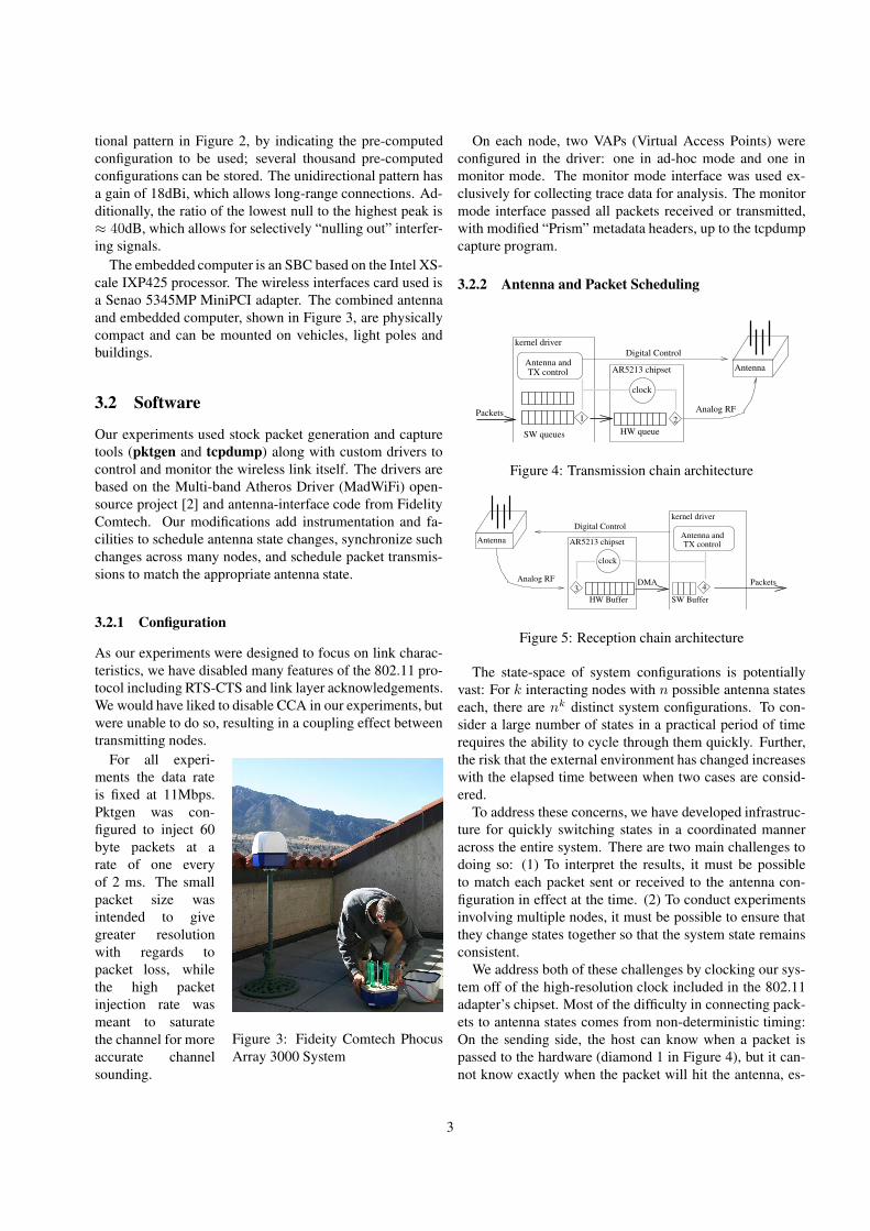
On each node, two VAPs (Virtual Access Points) wereconfigured in the driver: one in ad-hoc mode and one inmonitor mode. The monitor mode interface was used ex-clusively for collecting trace data for analysis. The monitormode interface passed all packets received or transmitted,with modified “Prism” metadata headers, up to the tcpdumpcapture program.
3.2.2 Antenna and Packet Scheduling
kernel driver
AR5213 chipsetTX controlAntenna and
clock
1 2
SW queues
Antenna
Analog RF
HW queue
Packets
Digital Control
Figure 4: Transmission chain architecture
kernel driver
AR5213 chipsetAntenna TX controlAntenna and
clock
3 4
Digital Control
Analog RF
HW Buffer SW Buffer
DMA Packets
Figure 5: Reception chain architecture
The state-space of system configurations is potentiallyvast: For k interacting nodes with n possible antenna stateseach, there are nk distinct system configurations. To con-sider a large number of states in a practical period of timerequires the ability to cycle through them quickly. Further,the risk that the external environment has changed increaseswith the elapsed time between when two cases are consid-ered.
To address these concerns, we have developed infrastruc-ture for quickly switching states in a coordinated manneracross the entire system. There are two main challenges todoing so: (1) To interpret the results, it must be possibleto match each packet sent or received to the antenna con-figuration in effect at the time. (2) To conduct experimentsinvolving multiple nodes, it must be possible to ensure thatthey change states together so that the system state remainsconsistent.
We address both of these challenges by clocking our sys-tem off of the high-resolution clock included in the 802.11adapter’s chipset. Most of the difficulty in connecting pack-ets to antenna states comes from non-deterministic timing:On the sending side, the host can know when a packet ispassed to the hardware (diamond 1 in Figure 4), but it can-not know exactly when the packet will hit the antenna, es-
3

pecially if the card performs CCA and CSMA/CA backoff.Similarly, there is a variable delay between when the packetpasses through the receiving antenna and when the host’s in-terrupt handler is called to service the packet (diamond 4 inFigure 5). To know the states of the antennas at whatevermoment the signal actually passed through them would re-quire allowing a significant guard slot around each change.
While there is a large margin of error as to what the sys-tem time was when the packet was actually sent, the MACtime can be known much more precisely. The MAC time,used for calculating retransmission timeouts, back-offs andthe like, is maintained by a high-precision clock on the in-terface card. Packets are stamped by the hardware with theMAC time upon arrival (diamond 3), so there is almost nonon-deterministic delay between the actual reception and thetime-stamp. Because the AR5213 chipset also makes thistime available to the host, antenna transitions are scheduledrelative to the MAC time. This means that, using the re-ceived packet’s time stamp, the antenna states can be muchmore precisely determined. Note that the variable delay be-tween 1 and 2 still affects the ability to control or predict thestate in which a packet will be sent. What is gained is theability to determine, for those packets which are success-fully received, the state in which they were sent.
Using the on-chip timer helps with the second challenge:MAC time synchronization is already required by the 802.11protocol and is done in the interface hardware. In both BSSand IBSS (ad-hoc) modes, stations include their MAC timein beacon packets. Listening stations then set their ownclocks off the beacons. Because this is done in the chipset(diamonds 2 and 3), the variability in delay is much lower –and thus the synchronization much tighter – than what canbe achieved using software on the end hosts.
4 Experimental Setup and Design
4.1 Sites
To evaluate our experimental tools and to gain insight intothe behavior of phased array antennas, we performed ex-periments in two different environments. The first environ-ment consisted of four car mounted arrays on the perimeterof an open field where the topology exhibited relatively longlinks with clear line of sight. The second consisted of 3 carmounted arrays and one fixed building-mounted array. Thecar-mounted arrays were in parking areas around the Uni-versity of Colorado at Boulder campus, one of which wasan elevated ramp. The fourth array was mounted on the sev-enth floor of the Engineering Center. In this environment,the links are shorter but the paths are highly occluded.
4.1.1 NxN Scanning
The first set of experiments was designed to characterize thelink quality when using different combinations of transmit-ter and receiver antenna patterns. Given the 17 patterns,omni plus 16 directional, we explored the complete statespace comprised of 289 transmitter/receiver tuples for eachof 4 transmitters. In total, 1156 tuples were assessed.
The NxN scan consisted of four sub-experiments, eachof which has one of the nodes transmitting for 180 secondswhile rotating its antenna pattern. The other three nodes didnot transmit, and instead received while rotating their an-tenna patterns. The TDM schedules of all nodes were iden-tical and consisted of 17 slots, each slot using one of the17 antenna patterns. When a node was a receiver the slotlength was set to 40 ms, resulting in one complete cycle ofthe receiver antenna patterns every 680 ms. When transmit-ting, the slot length of the node was set to 680 ms so asto allow each receiver to complete one cycle for every slotof the transmitter. The length of each sub-experiment was180 seconds, resulting in each receiver gathering data forapproximately 16 iterations of all 289 transmitter/receivertuples.
4.1.2 Independent Link Pairs
To determine the effect of interferers, we considered the twolinks A-B and C-D. The experiment consisted of two sce-narios performed in sequence. The first had node A trans-mitting to node B and node C transmitting to node D, whilethe second differed only in the fact that node D transmittedto node C instead of vice versa.
To avoid an exhaustive N 4 search of the possible antennaconfigurations, we considered only a subset consisting ofthe top 100 configurations for each of the two links. Theranking was determined by the number of received packetsper slot for each configuration in the NxN scan. For both ofthe scenarios, nodes A and B had slot times of 40 ms whilenodes C and D had slot times of 4 seconds. With this, A andB will step through all 100 slots for each slot of C and D.Hence, one complete cycle of system wide antenna config-urations takes 400 seconds; we allowed for three completecycles.
5 EvaluationIn this section, we evaluate how well the experimental sys-tem addresses the challenges identified in Section 2.
5.1 MetricsThe experiments in Section 4 were conducted as part of aneffort to characterize the impact of antenna direction on link-layer network performance. This brings up two related eval-
4

uation problems: (1) How does one measure the goodnessof the network as a whole? (2) How does one measure thegoodness of its components? We don’t have any conclusiveanswers, but we can shed some light on the strengths andweaknesses of several possible metrics.
A good component metric would be something locally-measurable that’s also a good predictor of overall goodness.In the context of radio links, two widely-used metrics aresignal strength and signal to interference and noise ratio(SINR). Signal strength is relatively easy to measure, andis widely used in practice. For instance, most 802.11 im-plementations use signal strength to select a base station toassociate with.
Figure 6 shows Throughput and RSSI for Experiment 3
RSSI (dBm)
Thro
ughp
ut (B
ytes
/ S
lot)
0
500
1000
1500
2000
!90 !80 !70 !60 !50
Figure 6: RSSI and throughput ag-gregated across campus and field ex-periments.
the relationshipbetween RSSI andthroughput overan aggregate ofseveral experimentsin the presenceof interference.Several limitationsare apparent to thenaked eye: First,the RSSI bounds themaximum through-put fairly clearly,but leaves a great deal of variation unaccounted for. Sec-ond, its predictive value diminishes significantly above a(modulation-dependent) threshold. Third, there are clearclusters in the data, suggesting that the variation is relatedto some structured process and is not purely random.
To the extent that the other process is related to interfer-ence, SINR would be expected to account for it. In prac-tice, SINR is difficult to define – let alone measure – for in-termittent interference like packet-oriented communication.At any given instant, there’s a meaningful interference level,but its true for that moment only. Our research looked atlonger term measures like signal to peak interference or sig-nal to average interference, but found even less correlationthan with pure RSSI.
It’s clear that signal strength and interference (at the re-ceiver) affect the quality of any radio link, but it’s not clearwhat the best practically-observable predictive metric is.When protocol-specific behavior (like CSMA/CA) is con-sidered, it becomes more complicated, as conditions at thesender affect throughput as well.
We have considered two system-level metrics in these ex-periments: Throughput and packet error rate. For a fixedtransmission rate, they are interchangeable. However, theygive fairly different views of the system in practice: Be-cause of the “clear channel assessment” (CCA) aspect of the802.11 protocol, heavy traffic near the transmitter inhibitsit from sending. This reduces the throughput but doesn’t
Tran
smitt
er A
nten
na P
atte
rn
13
57
911
1315
0
0
RSSI C!D
Receiver Antenna Pattern
1 3 5 7 9 11 13 15
!90
!80
!70
!60
!50
Tran
smitt
er A
nten
na P
atte
rn
13
57
911
1315
0
0
RSSI C!D
Receiver Antenna Pattern
1 3 5 7 9 11 13 15
!90
!80
!70
!60
!50
Figure 7: RSSI values forcampus C"D link on day2 for each pair of antennastates.
Figure 8: RSSI values forcampus C"D link on day1 for each pair of antennastates.
change the packet error rate appreciably.Neither metric gives a truer view of the situation than the
other: Packet error rate is a purer representation of the ra-dio link as such, but throughput is a better indicator of howuseful the link is to users with this type of hardware.
5.2 Directionality Under a Dynamic Environ-ment
Wireless systems in the real-world are difficult to model be-cause they can change over time. In order to gain an un-derstanding of how this variability affects our experimentalplatform, we conducted our NxN scan over several short pe-riods of time (minutes), separated by a long period of time(days), as well as in two different locations (a flat farm fieldand a cluttered campus environment).
In Figures 9, 8, and 7 we show a selected sample of theexperimental results of these scans. State “0” indicates theomnidirectional antenna pattern.
In each figure we see
Tran
smitt
er A
nten
na P
atte
rn
13
57
911
1315
0
0
RSSI B!D
Receiver Antenna Pattern
1 3 5 7 9 11 13 15
!90
!80
!70
!60
!50
Figure 9: RSSI values for fieldlink B"D for each pair of an-tenna states.
clear indicators of eachnode’s main antenna lobeas well as side lobes andvarious “nulls”. Clearlythe difference in loca-tion, as well as link dis-tance plays a large role indetermining the outcomeof the experiment. InFigure 8 we see that mul-tipath on the campus alsoplays a significant role inmaking secondary lobesless distinguishable thanin the less obstructed field location (see Figure 9).
Looking at the variation of RSSI between two days, wesee that the same campus link has changed significantly.Figures 7 and 8 depict the average RSSI on the campus link
5

Tran
smitt
er A
nten
na P
atte
rn
13
57
911
1315
0
0
Coefficient of Variation of RSSI
Receiver Antenna Pattern
1 3 5 7 9 11 13 15
0.00
0.01
0.02
0.03
0.04
Tr
ansm
itter
Ant
enna
Pat
tern
13
57
911
1315
0
0
Coefficient of Variation of RSSI
Receiver Antenna Pattern
1 3 5 7 9 11 13 15
0.00
0.01
0.02
0.03
0.04
Figure 10: Coefficient ofvariation for field RSSImeasurements. (Scale: 0.0– 0.04)
Figure 11: Coefficientof variation for campusday 1 RSSI measurements.(Scale: 0.0 – 0.04)
C " D for each antenna state combination. Figure 8 depictsthe results on day 1 and Figure 7 shows day 2.
The two are both qualitatively and quantitatively differ-ent: Day 2 has higher overall values, and also a clearer bandstructure showing the antennas’ nulls and secondary lobes.These two differences do not automatically go together: Fig-ure 9 shows a measurement taken at the field site. The signalstrengths are lower than in either campus measurement, butthe structure is at least as regular as in Figure 7.
We then evaluated the consistency of our RSSI measure-ments within each 3 minute trial by calculating the coeffi-cients of variation ( !
µ ), shown in Figures 10 and 11. We ob-served that the short-term variability was much lower thanthat seen either between days or between sites. It is also in-teresting to note that the level of variability seems similaracross different experiments, even when the results them-selves are very different.
6 RelatedVarious researchers have examined the performance of re-alworld 802.11 based mesh networks [3]. A general find-ing is that these networks do not perform nearly as well assimulation might suggest. Bicket et al. [3] provide an as-sessment of a real-world 802.11b mesh network, Roofnet.They find that the distinction between nodes that are in-range and out-of-range to be indistinct and that multipathfading strongly influences loss rates for many of the links.Roofnet is based on a mesh of omnidirectional antennas.Ramanathan examines the performance of ad hoc networksbuilt with beamforming antennas [4]. This work, based onsimulation, shows under what conditions directional anten-nas wight be beneficial. In later work, Ramanathan et al.,describe an implementation of directional antennas and pro-pose a new MAC protocol to manage backoff periods ina manner appropriate to such networks. Other researchershave examined aspects such as range control and routing
in directional antenna MANETs [5, 6], scheduling algo-rithms [7] and MAC protocol variations [8, 9, 10, 11] fordirectional ad hoc networks.
7 ConclusionsIn this paper we presented a platform and an experimen-tal methodology by which the use of directional antennascan be evaluated systematically. Time-coordinated antennasteering makes it possible study the effects of directionality– for fixed and steerable systems – in ways that could not bedone with only fixed equipment.
We discus important metrics for characterizing these di-rectional links. There are inter-node and environmental in-teractions that make measures like RSSI insufficient, andthere are system-level effects that make it difficult to choosea metric which isolates the properties of interest.
Finally, we examined the consistency of measurementsacross multiple environments and time scales. These re-sults lead to two observations: First, the environment heav-ily influences the structure of how antenna patterns interact.Techniques which depend on predictable null and lobe ef-fects may work in some environments, but are likely to failin others. Second, environmental variability in the long termis much greater than in the short term. Experimental trialsshould be short, so that the different cases can be examinedunder comparatively consistent circumstances. Experimentsshould also be repeated over a longer term (and in differentlocations) to verify that results hold over a range of condi-tions.
8 AcknowledgementsThis work was supported by NSF Projects #0435297,#0454404, #0435452.
References[1] Preston Marshall. Wireless adaptive network node program.
http://www.darpa.mil/sto/solicitations/WANN/sn.htm, Mar 2006.
[2] Multiband atheros driver for wifi. http://madwifi.org/.
[3] Daniel Aguayo, John Bicket, Sanjit Biswas, Glenn Judd, andRobert Morris. Link-level measurements from an 802.11bmesh network. In Proc. Sigcomm 2004. ACM, August 2004.
[4] Ram Ramanathan. On the performance of ad hoc networkswith beamforming antennas. In MobiHoc ’01: Proceed-ings of the 2nd ACM international symposium on Mobile adhoc networking & computing, pages 95–105, New York, NY,USA, 2001. ACM Press.
6

[5] Mineo Takai, Junlan Zhou, and Rajive Bagrodia. Adaptiverange control using directional antennas in mobile ad hoc net-works. In MSWIM ’03: Proceedings of the 6th ACM inter-national workshop on Modeling analysis and simulation ofwireless and mobile systems, pages 92–99, New York, NY,USA, 2003. ACM Press.
[6] A Nasipuri, J Mandava, H Manchala, and R.E Hiromoto.On-demand routing using directional antennas in mobile adhoc networks. Computer Communications and Networks,2000. Proceedings. Ninth International Conference on, pagesno.pp.535–541, 2000.
[7] Lichun Bao and J.J. Garcia-Luna-Aceves. Transmissionscheduling in ad hoc networks with directional antennas. InMobiCom ’02: Proceedings of the 8th annual internationalconference on Mobile computing and networking, pages 48–58, New York, NY, USA, 2002. ACM Press.
[8] Thanasis Korakis, Gentian Jakllari, and Leandros Tassiulas.A mac protocol for full exploitation of directional antennas inad-hoc wireless networks. In MobiHoc ’03: Proceedings ofthe 4th ACM international symposium on Mobile ad hoc net-working & computing, pages 98–107, New York, NY, USA,2003. ACM Press.
[9] Yihu Li and Ahmed M. Safwat. Efficient deafness avoidancein wireless ad hoc and sensor networks with directional an-tennas. In PE-WASUN ’05: Proceedings of the 2nd ACMinternational workshop on Performance evaluation of wire-less ad hoc, sensor, and ubiquitous networks, pages 175–180,New York, NY, USA, 2005. ACM Press.
[10] Siuli Roy, Dola Saha, S. Bandyopadhyay, Tetsuro Ueda, andShinsuke Tanaka. A network-aware mac and routing proto-col for effective load balancing in ad hoc wireless networkswith directional antenna. In MobiHoc ’03: Proceedings ofthe 4th ACM international symposium on Mobile ad hoc net-working & computing, pages 88–97, New York, NY, USA,2003. ACM Press.
[11] Mineo Takai, Jay Martin, Rajive Bagrodia, and Aifeng Ren.Directional virtual carrier sensing for directional antennas inmobile ad hoc networks. In MobiHoc ’02: Proceedings ofthe 3rd ACM international symposium on Mobile ad hoc net-working & computing, pages 183–193, New York, NY, USA,2002. ACM Press.
7


![Iff Iff - Saferworld AAcronyms cronyms --zAb–;zAb–;+I+Iff]k]k__ AAFNFN--PG6PG6]g]gf kmfpG8f kmfpG8];];g gg g]k]kfn_ fn_ AAntenna Foundation Nepal ntenna Foundation Nepal AAPFPF--;z:q](https://static.fdocuments.in/doc/165x107/5fa40f5da63bcf21ce2d41c5/iff-iff-saferworld-aacronyms-cronyms-zabazabaiiffkk-aafnfn-pg6pg6ggf.jpg)


