A novel Low Temperature Co-firing Ceramic (LTCC) material...
50
A NOVEL LOW TEMPERATURE CO-FIRING CERAMIC (LTCC) MATERIAL FOR TELECOMMUNICATION DEVICES HELI JANTUNEN Department of Electrical Engineering and Infotech Oulu, University of Oulu OULU 2001
Transcript of A novel Low Temperature Co-firing Ceramic (LTCC) material...

A NOVEL LOW TEMPERATURE CO-FIRING CERAMIC (LTCC) MATERIAL FOR TELECOMMUNICATION DEVICES
HELIJANTUNEN
Department of Electrical Engineering andInfotech Oulu, University of Oulu
OULU 2001

HELI JANTUNEN
A NOVEL LOW TEMPERATURE CO-FIRING CERAMIC (LTCC) MATERIAL FOR TELECOMMUNICATION DEVICES
Academic Dissertation to be presented with the assent ofthe Faculty of Technology, University of Oulu, for publicdiscussion in Kajaaninsali (Auditorium L 6), Linnanmaa, onDecember 7th, 2001, at 12 noon.
OULUN YLIOPISTO, OULU 2001

Copyright © 2001University of Oulu, 2001
Manuscript received 31 October 2001Manuscript accepted 7 November 2001
Communicated byProfessor Heiko ThustDoctor Esa Kemppinen
ISBN 951-42-6553-X (URL: http://herkules.oulu.fi/isbn951426553X/)
ALSO AVAILABLE IN PRINTED FORMATISBN 951-42-6552-1ISSN 0355-3213 (URL: http://herkules.oulu.fi/issn03553213/)
OULU UNIVERSITY PRESSOULU 2001

Jantunen, Heli, A novel Low Temperature Co-firing Ceramic (LTCC) material fortelecommunication devices Department of Electrical Engineering and Infotech Oulu, University of Oulu, P.O.Box 4500, FIN-90014 University of Oulu, Finland 2001Oulu, Finland(Manuscript received 31 October 2001)
Abstract
The thesis describes the development of a novel LTCC material system for RF and microwavetelecommunication purposes.
The work has been divided into three parts. In the first section, the compositional and firingproperties of this novel LTCC dielectric have been studied as well as its thermomechanical anddielectric properties. The second section describes the multilayer component preparation procedurefor the ceramic material including tape casting and lamination parameters and the selection of theconductor paste. In the last section, the novel LTCC material system has been used to demonstrate itsproperties in RF multilayer resonators and a bandpass filter.
The dielectric material for the novel LTCC system was prepared using magnesium calciumtitanate ceramic, the firing temperature of which was decreased to 900°C by the addition of a mixtureof zinc oxide, silicon oxide and boron oxide. The powder was made without any prior glasspreparation, which is an important process advantage of this composition. The fired microstructurewas totally crystalline with high density (3.7 Mg m-3) and low porosity (0.5 %). The mechanicalproperties were virtually identical to the values of the commercial LTCCs, but the higher thermalexpansivity makes it most compatible with alumina substrates. The dielectric values were also good.The permittivity was 8.5 and the dissipation factor (0.9•10-3 at 8 GHz) less than that of thecommercial LTCCs. Furthermore, the temperature coefficient of the resonance frequency wasdemonstrated to be adjustable between the range of +8.8 ... -62 ppm/K with a simple compositionalvariation of titanium oxide.
The slurry for the tape casting was prepared using poly(vinyl butyral) -base organic additives andthe 110 µm thick tapes had a smooth surface (RA < 0.5 µm). The multilayer components wereprepared using 20 MPa lamination pressure, 90°C temperature and 1 h dwell time. The most suitableconductor paste for this composition was found to be commercial silver paste (duPont 6160), whichproduced satisfactory inner and outer conductor patterns for multilayer components. Finally,resonators with a resonant frequency range of 1.7 ... 3.7 GHz were prepared together with a bandpassfilter suitable for the next generation of telecommunication devices. This demonstration showed thepotential of the developed novel LTCC material system at high RF frequencies.
Keywords: ceramic materials, LTCC materials, microwave properties, telecommunicationdevices
Aikaa myötenajan tajun aistimilla,alkaa ympäristö yllättää,aivot ymmärtääerilaista elomuotoaekologista elinkaarta,tulee tutuksi tulevaisuusja haluaa hallitahiukkasen
Omistettu hyvälle ystävälleni Helilleväitöspäivänä,
kiitoksena lukuisista ja monimuotoisista keskuste-luista
matkan varrella
Kaisa Kerätär

Acknowledgements
First of all, I wish to thank my supervisor Professor Seppo Leppävuori, who arranged theopportunity to do this research with circumstances I was never able to dream. I am alsomost grateful to Dr. Antti Uusimäki, the mental tutor of this work, for his encouragingand endless support from the very first beginning. The valuable advice from ProfessorRisto Rautioaho is also appreciated. The role of Mr. Aimo Turunen was also importantespecially in the electromagnetic simulations. I am also grateful to everyone in the Micro-electronics and Materials Physics Laboratory for the unreserved working atmosphere andespecially Mr. Timo Vahera for his tireless help in many ways. The staff of the Institute ofElectron Optics, University of Oulu, and especially Ms. Raija Peura and Mr. Olli Taikina-aho have supported my work with excellent professional skills and a helpful attitude.Many people from Materials Engineering Laboratory have also helped with practicalwork. I am very grateful to Dr. A. E. Hill for revising the English language of the manu-script.
This work was financially supported by the Academy of Finland, Tauno TönningFoundation, Nokia Foundation and Electronic Materials, Packaging and Reliability Groupof Infotech Oulu, all of which are gratefully acknowledged.
Special thanks are to be expressed to my long lasting friend, Ms. Kaisa Kerätär, whowrote the poem for this thesis, to all my friends, who have been patient with this one topicin my recent life and to my former colleagues and supervisors, who have taught me somuch. I also thank my little sister, Ms. Marjaana Kymäläinen and her family.
Finally, my deepest gratitude is dedicated to my husband and better half, Mr. JuhaniAsunmaa, who has shared with me many varying stages of life.
I thank you all!
Oulu, October 2001 Heli Jantunen

List of abbreviations and symbols
εr permittivityλ wavelength ρ bulk densityσf fracture strength τe temperature coefficient of dielectric constantτf temperature coefficient of resonance frequency
a half length of indent diagonalBE back scattering mode in SEM C capacitancec radial crack lengthDF Dissipation FactorE Young’s modulus (elastic modulus)EDS Energy Dispersive SpectrometerFESEM Field Emission Scanning Electron MicroscopeGPS Global Positioning SystemHTCC High Temperature Co-fired CeramicHv Vickers hardnessJCPDS Joint Committee of Powder Diffraction StandardKIC fracture toughnessL inductanceLTE Linear Thermal ExpansivityLTCC Low Temperature Co-fired CeramicMCM Multi-Chip ModulePCB Printed Circuit BoardPEG Polyethylene glycolPVA Polyvinyl alcoholPVB Poly(vinyl butyral)R resonatorRA arithmetic average roughnessRF Radio Frequency

SAM Scanning Acoustic MicroscopeSEM Scanning Electron MicroscopeSSA Specific Surface AreaTE Transverse Electric fieldTEM Transverse ElectroMagnetic fieldTM Transverse Magnetic fieldvc compressional velocity of acoustic wavevs shear velocity of acoustic waveXRD x-ray diffraction
List of original papers
Original papers, presented at the end of the thesis, are referred to throughout the text bytheir roman numbers.
I Jantunen H, Rautioaho R, Uusimäki A & Leppävuori S (2000) Compositions ofMgTiO3- CaTiO3 ceramic with two borosilicate glasses for LTCC technology. TheJournal of European Ceramic Society, No. 20, pp. 2331-2336.
II Jantunen H, Rautioaho R, Uusimäki A & Leppävuori S (2000) Preparing low lossLTCC material without glass addition. The Journal of American Ceramic Society,Vol. 83, No. 11, pp. 2855-2857.
III Jantunen H, Uusimäki A, Rautioaho R & Leppävuori S. The effect of processingroute on the thermomechanical properties of a low temperature firing ceramic forelectronic packaging. Accepted to the British Ceramic Transactions, 2001.
IV Jantunen H, Uusimäki A, Rautioaho R & Leppävuori S. The temperature coefficientof microwave resonance frequency of a LTCC system. Accepted to the Journal ofAmerican Ceramic Society, 2001.
V Jantunen H, Turunen A, Leppävuori S & Uusimäki A. Meshed and uniform groundplanes on LTCC strip line resonators and bandstop filters. Submitted to the IEEETransactions on Components and Packaging Technologies, 2001.
VI Jantunen H, Leppävuori S, Turunen A & Uusimäki A. Multilayer resonators and abandpass filter fabricated from a novel Low Temperature Co-fired Ceramic (LTCC).Accepted to the Journal of Electronic Materials, 2001.
The object of paper I was to introduce a novel dielectric ceramic for the LTCC process.It presents compositional studies and basic methods used for microstructure and firinginvestigations. As a result, the sintering temperature of the well-known dielectric ceramic(MgTiO3-CaTiO3) was decreased from 1360°C to 900°C, suitable for the LTCC process.

Paper II describes a straightforward method of making this novel LTCC materialwithout any prior glass preparation route. The results showed that this method produced acomposition with improved firing properties more suitable for the LTCC process withoutimpairment of the microstructural and dielectric properties.
In papers III and IV, the main purpose was to determine the thermomechanicalproperties of this low firing ceramic and to demonstrate the possibility of optimising thetemperature coefficient of the resonance frequency. The achieved results were comparedwith the properties of commercial LTCC materials. The thermomechanical properties ofthis novel LTCC dielectric with the straightforward preparation route were good, theessential dielectric dissipation factor was low and the temperature stability of theresonance frequency was shown to be adjustable through compositional variation.
Papers V and VI describe structures, modeling and preparation methods and alsomeasured values of designed multilayer RF resonators and filters. In paper V, acommercial LTCC material system was used and the effects of meshed and uniformground planes on the Q-factor of the resonators were studied. According to these results,paper VI describes the preparation of multilayer resonators and a bandpass filter from thenovel LTCC dielectric using uniform ground planes. This paper also describes tapecasting and lamination parameters of the novel low firing dielectric ceramic and theselection of a suitable conductor paste. Thus, paper VI is an applicational demonstrationof performance of the whole novel LTCC material system. It was shown that it is suitablefor multilayer RF and microwave components and the achieved values of resonators andfilter were excellent.
The experimental tests of papers I-IV were the contribution of the author. In papers Vand VI, the experiments and simulations were done in association with the co-authors andstaff and basic ideas were the contribution of the author. The manuscripts for publicationswere written by the author with the kind help of the co-authors.

Contents
Abstract Acknowledgements List of abbreviations and symbols List of original papers 1 Introduction . . . . . . . . . . . . . . . . . . . . . . . . . . . . . . . . . . . . . . . . . . . . . . . . . . . . . . . . 15
1.1 The LTCC material system for RF and microwave components . . . . . . . . . . . . 151.2 Objective and outline of this thesis . . . . . . . . . . . . . . . . . . . . . . . . . . . . . . . . . . . 16
2 Development of a LTCC dielectric material . . . . . . . . . . . . . . . . . . . . . . . . . . . . . . . 182.1 Basis of the dielectric materials for the LTCC process . . . . . . . . . . . . . . . . . . . . 182.2 Test sample preparation and measurements . . . . . . . . . . . . . . . . . . . . . . . . . . . . 212.3 Investigated compositions and the results . . . . . . . . . . . . . . . . . . . . . . . . . . . . . . 25
3 Material development for the multilayer process . . . . . . . . . . . . . . . . . . . . . . . . . . . 313.1 Demands of the LTCC material systems . . . . . . . . . . . . . . . . . . . . . . . . . . . . . . . 313.2 Determination of the process parameters . . . . . . . . . . . . . . . . . . . . . . . . . . . . . . 34
4 Properties of the multilayer RF components . . . . . . . . . . . . . . . . . . . . . . . . . . . . . . . 385 Conclusions . . . . . . . . . . . . . . . . . . . . . . . . . . . . . . . . . . . . . . . . . . . . . . . . . . . . . . . . 43References . . . . . . . . . . . . . . . . . . . . . . . . . . . . . . . . . . . . . . . . . . . . . . . . . . . . . . . . . . . . 45Original papers


1 Introduction
1.1 The LTCC material system for RF and microwave components
Telecommunication technology industry today requires high volume and low cost circuitfabrication, while at the same time demanding excellent electrical performance, reliabili-ty, circuit miniaturisation and surface mounting techniques. [Barnwell et al. 2000, Miy-ake et al. 1999]. Recently, Low Temperature Co-fired Ceramics (LTCCs) have beenintensively studied for these applications. Although ceramic materials have been used forRF filters, resonators and antennas for several decades [Wakino et al. 1987, Fujishima2000, Alford et al. 1997, Mizoe et al. 1999, Shutler et al. 1997, Huang & Lin 2000Dakeya et al. 2000], LTCC technology has now attained the level of a real combinationof dielectric ceramic layers with embedded electrodes made of high conductivity metalssuch as silver or copper. [Barnwell et al. 2000, Tummala 1991, Sheen 1999] LTCC tech-nology provides a promising way to realise high quality multi-chip modules (MCM)which have huge market prospects. [Scrantom & Gravier 1999] The major RF opportuni-ties are in the fields of mobile telecommunication devices (0.9–2 GHz), wireless localnetworks such as Bluetooth (2.4 GHz), geographical positioning such as GPS (1.6 GHz)and in broad band access connection systems (5.8–40 GHz). [Barnwell et al. 2000]
LTCC technology possesses several advantages making it suitable for mass markettelecommunication applications. The process itself enables high yield, fast turnaroundand reduced cost of devices with three dimensional microwave structures. Thiscombination, together with the possibility of fabricating fine conductive lines and spaces,small interconnect vias and high dielectric layer counts leading to high density packaging,has recently resulted in intensive research into LTCC technology. [Barnwell et al. 2000]Additionally, using computer aided component design and simulation systems, LTCCfilters have been produced with 100% yield up to tolerances in materials andmanufacturing processes. [Bailey et al. 1997]
The key areas for LTCC technology are the development of the material and theprocess, and component design and reliability, which all form their own field of researchrequiring a wide understanding of the subject. On the other hand, a real functional LTCCsystem cannot be developed if any of these areas are neglected.

16
In the development of a novel dielectric material for the LTCC system, the electricaland thermomechanical demands are obvious for enabling the production and usage ofreliable components. In the special case of RF applications, the dielectric properties suchas low dissipation factor (DF), appropriate permittivity (εr) and near zero temperaturecoefficient of the resonance frequency (τf) are important. These three values enable theconstruction of RF filters with convenient size, low insertion loss, a steep cut-off andoperational stability of the performance curve at ambient temperatures. [Penn et al. 1997]
After successful development of the novel dielectric material, it should be employed ina multilayer process. This first requires the preparation of a green dielectric tape, which isitself at the state of the art. Tape suitable for multilayer manufacturing needs to withstandhandling and via punching and produce, after lamination and low temperature co-firing, asolid material with the desired properties. [Cahn et al. 1996, chap. 7] A good surfacesmoothness and compatibility with embedded conductive lines are also essentialproperties. [Sheen 1999, Barnwell et al. 2000]
The last decade has seen the appearance of many commercial LTCC material systemsincluding ceramic tapes and suitable conductor and resistor pastes (duPont 951 and 943,Ferro A6-5-M-13, Heraeus CT700) and their electrical and thermomechanical propertieshave been well reported. [Barnwell et al. 2000, Jones et al. 2000, Amey et al. 2000,Scrantom & Gravier 1999] This development has accelerated their utilisation, butalthough microwave components have already been constructed [Sheen 1999, Liang et al.1999, Miyake et al. 2000], improved ceramics are still needed. In particular, only a fewLTCC materials for RF applications, with the combination of low DF and optimisedtemperature coefficient of the resonance frequency, have been introduced. [Barnwell et al.2000, Kagata et al. 1992]
After these two stages of development, the novel LTCC material system can be testedin a real multilayer RF and microwave component. In the case of commercial LTCCmaterial systems, the material and tape preparations do not need to be arranged.Information from commercial material manufacturers also guides users through theprocess steps giving the necessary material parameters for component design andpreparation.
1.2 Objective and outline of this thesis
The main target of this thesis has been to develop a novel LTCC dielectric for RF andmicrowave components. The basics of the already existing low temperature fired dielec-trics were first studied and the special demands of the multilayer preparation procedureand microwave components were taken into account. The stages of development shownin Fig. 1.1 were used to consider the requirements of the whole process. This means thatthe requirements set by RF components and the multilayer process could be taken intoaccount in material development. Similarly, a most suitable tape from the componentdesign standpoint could be prepared. The stages of the development were also able togive valuable feedback to each other.

17
Fig. 1.1. The stages of development used for a novel LTCC material system.
This thesis describes the literature studies and empirical work done to develop a novelLTCC material system and the content of the summary is as follows:
In Chapter 2, the background and the specifications for the novel dielectric LTCC arelaid down and the straightforward preparation method is presented. Furthermore, itintroduces the measurements and results of the most important thermomechanicalproperties of this ceramic material. The possibility of optimising its dielectric values isalso discussed.
The Chapter 3 describes the multilayer component preparation route for this dielectricmaterial including the parameters needed for tape casting, laminating and firing. Themicrostructural properties of the fired tapes were required to be the same as thoseachieved in the stage of the material development in the Chapter 2. This method was usedto ensure that the process had no effects on the final, fired dielectric material and thus onits properties. The selection of a suitable co-firing conductor material is also presented.
The design and structure of the multilayer resonators and filter chosen to demonstratethe abilities of this novel LTCC material system are outlined in Chapter 4 as well as theirmeasured properties at RF frequencies.
The objectives of this thesis is thus to introduce a novel LTCC material system startingfrom the compositional studies of the dielectric ceramic and its dielectric, firing andthermomechanical properties. Furthermore, the multilayer component preparationprocedure for this novel LTCC material system will be also presented. The author alsohopes that the thesis is able to give guidance when the same types of dielectric materialsare further developed.
Development of aNOVEL LTCC MATERIAL
Employment of the LTCC PROCESS
Designing, preparation and measurement of RF COMPONENTS
- tape casting procedure- multilayer process parameters- conductor paste selection
-component design and simulations-RF measurements- comparison with commercial LTCC
- theoretical study of material alternatives- test compositions- firing profile- termomechancial properties- dielectric properties

2 Development of a LTCC dielectric material
2.1 Basis of the dielectric materials for the LTCC process
Dielectric materials used for LTCC components have to have proper firing, dielectric andthermomechanical properties so that mechanically reliable multilayer structures with thedesired electrical performance can be produced.
“Proper” firing properties means that the dielectric material has to achieve a dense,non-porous microstructure below 950oC that it can be co-fired with low resistiveconductor materials such as silver or copper. This is a fundamental demand and cannot beneglected in any circumstances. Additionally, any densification or crystallisation of thecomposition should not start at too low a temperature because this can prevent theevaporation of the organics and solvents used in conductive pastes and dielectric and thuscause residual carbon traces in the microstructure. [Tummala 1991]
For commercial LTCCs, the firing profile is specified accurately in the informationgiven by the manufacturers and for new dielectric materials this is an essential part oftheir development. Fig. 2.1 shows a typical firing profile for LTCCs. The steps 1, 3 and 5are heating and cooling periods, step 2 is for burning out the organic additives and step 4is the actual sintering period.
Fig. 2.1. Typical firing profile for LTCC components.
12
3
4
5
Tem
pera
ture
Time

19
All these steps are typical for commercial LTCCs with only small variations in coolingand heating rates, maximum temperatures and dwell times caused by differentcompositions and additives. For duPont’s 943 material system the recommended co-firingprofile is presented in Table 1.
Table 1. Firing profile for duPont’s 943 LTCC material system.
The second requirement, dielectric properties, is of course one of the most importantfactors when LTCCs are developed specially for RF purposes and the most suitable valuesdepend on the applications. For RF components at least the permittivity, εr, the dissipationfactor, DF, (or Q-factor) and temperature dependence of the resonance frequency, τf, haveto be considered. These three properties define the quality and size of the RF component.The permittivity is especially important because the length of a resonator is inverselyproportional to the square root of the permittivity. [Wakino et al. 1987] Thus the footprintof RF components operating at low frequencies can increase to an inconvenient size if theεr is low. On the other hand, materials with too large a permittivity can also causeproblems because they need narrow and accurate lines for proper impedance matching.[Ludwig & Bretchko 2000, p. 65] The LTCC materials available commercially havepermittivities between 4–10 (Table 2), but larger values up to 85 have also been reportedin the literature for non-commercial materials. [Kagata et al. 1992, Kniajer et al. 1997]
Table 2. Dielectric properties of commercial LTCC dielectrics.
A low dissipation factor, DF, (or high Q-factor) is also an important property forLTCCs because it makes it possible to design RF filters with low losses. Although thisfact is well-known and the values should be and are reported for all commercial LTCCs(Table 2), in multilayer systems the conductive losses are more important. [Barnwell et al.2000] The dissipation factor is also commonly studied as a function of frequency.[Donahue et al. 1998]
Temperature / °C rate or dwell time 20–400 9.2°/min400–600 4.7°/min600–850 11.4°/min850 15 min850–20 10°/min Total time 3 h 24 minPreliminary information from duPont
Material εr DF / 10–3 τf / ppm/KduPont 951* 7.8 1.5 @ 1 kHz –duPont 943** 7.5 1 @ 1 MHz –Ferro A6-5-M-13* 5.9 2 @ 10 MHz –Heraeus CT 700* 7.0 2 @ 1 kHz –Motorola T2000*** 9.1 1 @ 2 GHz < ± 10*LTCC design guide made by CTS Microelectronics, West Lafayette, IN, USA,** Preliminary information from duPont, *** [Barnwell et al. 2000].

20
The temperature dependence of the resonance frequency, τf, is rarely reported, but forRF filter applications a value between –10…+10 ppm/K is necessary for a stablefrequency response of the component at its operational temperature. [Barnwell et al.2000] This is a universal demand for all dielectric materials used for RF purposes becauseotherwise the temperature dependence of the component frequency has to becompensated with other arrangements such as special mechanical or electrical design.[Jantunen & Turunen 1994, Wang & Zaki 1999] At the present time only a fewcommercial LTCC materials fulfilling this demand have been reported. [Barnwell et al.2000, Kagata et al. 1992]
The third aspect, thermomechanical properties, should also be considered in dielectricmaterial development. This area includes a large variety of properties, which effect thereliable use of the designed component. A specific requirement is the linear thermalexpansivity (LTE) which should be matched closely to the value of the mounting boardused. This means that if the LTCC component is mounted on silicon the LTE should beabout 4⋅10–6 K–1, on alumina about 7–9⋅10–6 K–1 and on PCB nearly 20⋅10–6 K–1.[Tummala 1991, Mattox et al. 1988, Gektin et al. 1998] Furthermore, LTCCs have tomeet a number of mechanical requirements such as flexural strength, σf, hardness, Hv,surface smoothness, elasticity (or Young’s modulus), E and toughness, KIC, arising duringits fabrication and subsequent use. [Sheen 1999, Mattox et al. 1988, Amey et al. 2000]The values for commercial LTCCs, pure Al2O3 and some glass and glass-ceramics areshown in Table 3.
Table 3. Thermomechanical properties of commercial LTCCs, glasses, glass-ceramics andpure alumina.
These three aspects show that the development of the dielectric material for LTCCtechnology is at least a 3-dimensional problem demanding a large variety ofmeasurements. Additionally, the target values of each property cannot always be taken forgranted and depends on the intended application. The way in which the desired values canbe achieved also depends on the means by which the low temperature firing properties areobtained. There are two basic ways to arrange dielectric LTCC composition densificationat low temperatures. Firstly, crystalline dielectric ceramic is mixed with low melting
Property E GPa
σfMpa
Hv GPa
KICMPa/m1/2 LTEppm/K
duPont 951* 152 320 – – 5.8duPont 943** – 230 – – 4.5Ferro A6-5-M-13* 82 130 – – 7.0Heraeus CT 700* 91.8 240 – – 6.7Motorola T2000# – 230 – – 6.0
Al2O3+ ~ 400 300–400 13’ ~ 5 8.1
Glassceramic G55’ 110 200 6.8 – 5.5Cordierite’’ 130–150 150–300 – ~ 2.2 2.5^Celsia’’ ~ 69 ~ 87 – ~ 2.3 –*LTCC design guide made by CTS Microelectronics, West Lafayette, IN, USA, ** Preliminary Product DataSheet, + [Bever 1986, p. 155], ‘ [Tagami et al. 1997], ’’ [Sung & Kim 1999], ^ [Jean & Gupta 1994], # [Scran-tom & Gravier 1999].

21
temperature glass working as a fluxing agent. The final microstructure is then composedof dielectric particles in a glass matrix. [Tummala 1991, Knickerbocker et al. 1993] Thisis a very common method in commercial LTCCs as shown in the literature and, forexample, in duPont’s 943 dielectric composed of alumina particles in calcium aluminiumsilicates. [Jones et al. 2000] The achieved microstructure is dense and non-porous withproperly designed composition and firing, but the glass addition can impair themechanical and dielectric properties of the material. [Hing & McMillan 1973, p. 184,209]The second method is to use only glasses as starting materials and let them crystalliseduring the firing [Tummala 1991], thus avoiding glasses in the final microstructure.
In this thesis the target firing temperature was between 850–900°C because this is themost suitable range for commercial silver pastes. The desired dielectric andthermomechanical properties were basically the same as for the commercial LTCCs withsome exceptions. The target value for the LTE was allowed to be closer to the value ofalumina than silicon or PCB. Also the RF requirement of the τf was taken into accountvery carefully.
To achieve these properties, the basic compositional idea differed slightly from themethods described above. In this thesis the dielectric starting material was crystalline, awell-known mixture of magnesium titanate and calcium titanate (labelled as MgCaTiO3)ceramic. [Katoh & Ozeki 1994, Wood et al. 1996] This composition has a sinteringtemperature at about 1360°C and has been used for RF resonators and antennas becauseof its excellent dielectric properties. [Katoh & Ozeki 1994, Huang & Lin 2000] Thepermittivity of this material is ~ 18–20, the Q-factor ~ 3000–4600 at 6 GHz (DF ~ 3.3–2.2 ⋅10–4) and the τf can be adjusted to be very close to 0 ppm/K by varying the amount ofCaTiO3. [Katoh & Ozeki 1994] In this thesis the basic idea was to develop LTCC materialusing this dielectric composition and its properties as a base and decrease its firingtemperature to nearly 900°C, but in this thesis a totally crystalline microstructure wasaspired to because of its positive influence on dielectric and mechanical properties.[McMillan 1979, p. 184, 209]
2.2 Test sample preparation and measurements
The properties of different compositions were studied using oxide mixing and a drypressing procedure, because it is a simple method for the preparation of samples with themany different shapes needed for firing, dielectric and thermomechanical measurements.Later on, when the tape casting process was employed, the microstructure of the finaldielectric was used as the basic criterion to ensure that the process did not affect the prop-erties of the developed dielectric.
Fig. 2.2 shows the two sample preparation procedure producing compositions labelledas ZSB(g)/MMT-20 and ZSB(r)/MMT-20, respectively. [Paper II] The MMT-20 comesfrom a commercial name of the dielectric ceramic powder of MgCaTiO3, the firingtemperature of which has been decreased by using a mixture of Zinc, Silicon and Boronoxides (ZSB). Index ‘g’ in bracket denotes that the mixture has been prepared using glassand ‘r’ denotes the straight utilisation of the raw material oxides.

22
Following the route for producing the mixture ZSB(g)/MMT-20, glass was firstproduced by weighing the starting oxides and mixing for 1 h in a polyethylene pot millusing agate balls. The mixed powders were pressed into pellets which were subsequentlymelted in a platinum crucible. The melts were quenched in water, pulverised in the ballmill for 12 h, dried and screened through a 100 mesh sieve. The test mixtures where thenprepared by weighing different amounts of glasses and MgCaTiO3 ceramic, mixed in theball mill for 2 h together with polyvinyl alcohol (PVA) as a binder, polyethylene glycol(PEG) as a plasticiser and distilled water. The composition was dried in a microwaveoven and sieved. Uniaxial pressure and firing were then used to form different shape ofcompacts for various measurements. [Paper I]
Later on, when the most suitable composition with competitive dielectric propertiesand a high density, totally crystalline microstructure was found, a straightforward routewithout any glass preparation was also used (Fig. 2.2.) producing the final mixture ofZSB(r)/MMT-20. The same mixing and sieving procedure was also used for pureMgCaTiO3. [Paper II]
The specific surface area for all prepared powders was studied using a BET analyser(OmniSorb 360CX, Coulter Electronics Inc., Luton, UK) and their phases with x-raydiffraction (XRD) (Siemens D5000, Karlsruhe, Germany) utilising the JCPDS data file(International Center for Diffraction Data 1992, Swarthmore, PA, USA).
Fig. 2.2. Two different preparation routes for the novel LTCC dielectric. [Paper II]
Weighing and mixing ZnO, SiO , B O (*) in a ball mill
Drying and pelleting
Melting at 980 C and quenching in water
Grinding, dryingand sieving
Mixing with MMT-20(**)ceramic powder
Granulating in a ball millwith organic additives
Drying and sieving
Pressing
Firing
Weighing ZnO, SiO and B O (*)
ZSB(g)/MMT-20
ZSB(r)/MMT-20o
2 2 3
22 3
(**) Ex. Fuji Titanium Industry Co., Ltd.
(*) Ex. Johnson Matthey GmBH,Germany. ZnO (99 % purity), B O (99.9 % purity), SiO (99.5 % purity)
2 3
2

23
Cylindrical compacts with length of 18mm and diameter of 10 mm were used fordilatometric studies (Orton Automatic Recording Dilatometer, Westerville, OH, USA) tofind the firing properties for each composition. The densities and shrinkages of thesamples were calculated from their dimensions and weights after firing and themicrostructural and phase analyses were done using a Scanning Electron Microscope withEnergy Dispersive Spectrometer (SEM/EDS) (Jeol JSM-6400, Tokyo, Japan) or FieldEmission Scanning Electron Microscope (FESEM) (Jeol JSM-6300F, Tokyo, Japan) onground and polished surfaces. Boron contents were derived by determining the differencebetween the total determined constituents and 100%. Porosity values were estimated fromSEM or FESEM micrographs using the line intercept method.
The dielectric characteristics in the microwave frequency range were measured by thepost-resonator method first introduced by B. W. Hakki and P. D. Coleman in 1960. [Hakki& Coleman 1960] This method employs a cylindrically shaped specimen positionedbetween two copper plates, as shown in Fig. 2.3, which supports several TE and TMmodes. The TE011 has been used because it has been found most suitable and becauseidentification of this mode is easy. [Dube et al. 1997]
In this configuration, probes are situated on opposite side of the sample and theresonance frequency and the unloaded Q-factor are determined with a HP8719C networkanalyser. The equations required for calculating the permittivity have been detailed byKobayashi & Katoh [1985] but the calculation is nowadays done with a computer. Theexperiment is performed with weak coupling so that it does not affect the measuredvalues. This is one of the most accurate methods provided that the conductive losses ofthe conductive plates are low or their effects can be corrected.
Fig. 2.3. Measurement system of dielectric properties with Hakki-Coleman configuration.[Dube et al. 1997]
Also the samples should have suitable and accurate dimensions and the measurementhas to be done carefully and with an awareness of its limitations. Taking into accountthese facts, the Hakki-Coleman method is able to determine the permittivity with highaccuracy (~ 0.1%). Also, with large samples (diameter ~ 20 mm) this technique canproduce reliable DF results if DF is > 10–4 (Q-factor < 10 000) even at low frequencies.[Dube et al. 1997]
probe probe
sample
screw to move uppercopper plate
spring
movable copper plate
fixedcopperplate
probeholder

24
In this thesis the samples were pressed with a 25.5 mm diameter tool of lengthbetween 5–10 mm, fired and lapped and their dimensions were measured. The copperplates were also cleaned before each measurements and the coupling was arranged toproduce > 35 dB attenuation. [Papers I, II]
The measurements of the temperature dependence of the resonance frequency, τf, weredone using coaxial resonators. These samples were also made with the dry pressingprocedure and, after firing and dimensional measurements, they were coated withconductive paste (DT1402, Heraeus, West Conshohocken, PA, USA) to form λ/4resonators. The measuring system is shown in Fig. 2.4.
Fig. 2.4. Measurement systems for coaxial resonators. [Kemppinen & Leppävuori 1986]
Also in this case the coupling of the two probes to the electric field was arranged to below (< –35 dB) to avoid the effects of the measuring system. The resonance frequencieswere then measured with a HP8719C network analyser between temperatures of –30°Cand +80°C and the τf was calculated. This method was chosen because it takes intoaccount the temperature coefficient of the dielectric constant, τe, as well as the linearthermal expansivity, LTE, of the resonator itself, which is important from the practicalpoint of view. [Wakino et al. 1987, Kemppinen & Leppävuori 1986] This well-knownrelationship is given by the following equation (1).
τf= –1/2 τε –LTE (1)
Samples for thermomechanical studies were also made with the dry pressingprocedure. At this point the work concentrated on measurements of elastic modulus, E,hardness, Hv, strength, σf, fracture toughness, KIC, and linear thermal expansivity, LTE.All these properties are important because they can be correlated with fracture initiationby thermal stress or with the ability of cracks to propagate in material, both conditionsbeing associated with mechanical failure. High values of strength and thermalconductivity and low values of elastic modulus and thermal expansion coefficientincrease thermal stress resistance of the material. [Kingery, et al. 1976, p. 828] In thiscase, instead of thermal conductivity, the hardness of the materials was measured. Thehardness is basically the ability of a material to resist mechanical transformation, but ithas been established for ceramics to correlate with thermal conductivity. [Baesso et al.1999] Furthermore, the fracture toughness characterises the inherent ability of a crack topropagate after its initiation, but it can also be correlated with the size of the plastic zoneahead of the crack. [Kingery et al. 1976, p. 787]
probe probe
copper
contact

25
The elastic modulus, E, was measured with a scanning acoustic microscope (C-SAMD-9000, Sonoscan Inc., Bensenville, IL, USA) using a method reported by Canumalla &Oravecz. [1997] All samples had a diameter of 8.5 mm, but several different thicknessesbetween 0.61 and 0.92m mm (standard deviation ± 0.01 mm) were used for eachcomposition to ensure the measuring results. The elastic modulus was calculated usingEquation (2)
E=ρvs2(3vc
2–4 vs2)/( vc
2– vs2) (2)
where ρ is the bulk density. The vs is the shear velocity and vc
the compressional veloci-ty, which can be calculated if the thickness of the sample and respective wave propaga-tion times from a Scanning Acoustic Microscope (SAM) measurements are known.[Paper III]
The cross-breaking strengths were measured with 3-point loading on several nominallysquare section rods in the ‘as-fired’ state using an Instron machine. The spanning was 30mm and the loading rate 0.5 mm min–1. [Paper III]
The hardness and toughness of each fired composition were derived from polishedsamples using a Type M Shimadzu Micro Hardness Tester (Shimadzu Seisakuso Ltd.,Kyoto, Japan). The average Vickers Hardness values (Hv) and their standard deviationswere determined with a load of 100 g and dwell time of 15 s. The fracture toughness wascalculated using Equation (3)
KIC=0.028Hva1/2(E/Hv)1/2(a/c)3/2 (3)
where Hv is the Vickers hardness, E the elastic modulus, ‘a’ the half length of the indentdiagonal and ‘c’ the radial crack length. [Sung & Kim 1999] Toughness values and stan-dard deviations were determined with a 300 g load. [Paper III]
Finally, the Linear Thermal Expansivities, LTE, were measured using the dilatometerin a temperature range of 20–400°C. [Paper III]
2.3 Investigated compositions and the results
The basic dielectric material MMT-20 (MgCaTiO3) was delivered by Fuji TitaniumIndustry Co., Ltd. The specific surface area of the powder was 4.1 m2 g–1 and the XRDshowed only MgTiO3 crystals. [Paper I] The CaTiO3 could not be detected because of itssmall amount (2.3 mol%) in this mixture.
The number of possible different materials and compositions to decrease the firingtemperature of crystalline ceramic is countless, but some guiding principles for theselection process can be found. In this thesis a comprehensive literature study ofcompositions used earlier for other dielectric materials and also for commercial LTCCswas done as a first step. The reported effects of different compounds on the dielectricproperties of ceramic materials were also studied. The results showed that the mostcommon method was to use SiO2 based glass compositions. [Jones et al. 2000, Donahueet al. 1998, Tummala 1991] Especially with silicon oxide (SiO2) and aluminium oxide(Al2O3)-glasses containing MgO, boron oxide (B2O3) and phosphorus oxide (P2O5) hadgood firing properties and totally crystalline structures have been achieved with

26
moderately low amounts of glass addition. [Tummala 1991] Also, in some cases commonsintering aids were effective. [Kagata et al. 1992] On the other hand, alkaline metalsimpair the dielectric and mechanical properties and are thus not recommendable.[McMillan 1979, p. 209, Kingery et al. 1976, p. 940] Recently the addition of lead hasalso been avoided because of environmental considerations. [Donahue et al. 1998]
In this thesis the efficiency of several different sintering aids such as bismuth oxide(Bi2O3), lithium oxide (Li2O), zinc fluoride (ZnF) and copper oxide (CuO) and glassessuch as CaO-Al2O3-B2O3, Li2O-ZnO-SiO2 and MgO-Al2O3-SiO2 were first tested. Someof them were not able to decrease the firing at all and others, although producing quitemicrostructurally dense samples at low sintering temperatures, degraded the dielectricvalues. The most promising additions, BaO-SiO2-B2O3- and ZnO-SiO2-B2O3- glasses,were studied more carefully, but the first one was subsequently rejected. The secondglass, consisting of 60.3 mol% ZnO, 12.6 mol% SiO2 and 27.1 mol% B2O3, (codedZSB(g)), was prepared using high purity oxides and the pellets were melted at 980°Cbefore quenching.[Paper I] The composition is the same as that used successfully fordecreasing the firing temperature of BaTiO3. [Abe et al. 1996] The specific surface areaof the glass powder after milling was 2.4 m2 g–1 and the XRD analyses showedcrystalline Zn2SiO4 phase in an otherwise amorphous composition. [Paper I]
Different amounts of the ZSB(g) glass were mixed and granulated with MMT-20dielectric and the sinterability of this composition was measured using the dilatometer(Fig. 2.5). The results show that 70 wt% of the ZSB glass was needed for gooddensification, which occured in two stages. [Paper I]
Fig. 2.5. Shrinkage behaviour of the ZSB(g)/MMT-20 and ZSB(r)/MMT-20 compositions. [Pa-per I, II]
The first stage of sintering started at around 600°C and the second one at about 850°C.The SEM/EDS and XRD data for the materials in the as-mixed and dried condition, andafter firing at 620, 875 and 900°C, was studied and the density and porosity of thesamples were measured. [Paper I]
ZSB(g)/MMT-20ZSB(r)/MMT-20
20 170 320 470 620 770 9201.0
0.0
-1.0
-2.0
-3.0
-4.0
-5.0
-6.0
-7.0
Temperature / Co
Shrin
kage
/ %

27
As mentioned in Chapter 2.1, the starting material MMT-20 consisted of MgTiO3 andCaTiO3 crystals and the ZSB(g) glass of amorphous phases with Zn2SiO4 crystals. Thusthe compact before any heat treatments was a mixture of these phases. The compactdensity was 1.9 Mg m–3 with porosity about 47 %. [Paper I]
The set of samples fired at 620°C for 10 minutes showed slight densification withincreased density (2.2 Mg m–3) and decreased porosity (39 %). The microstructuralanalyses showed densified areas where glass had started to react with the crystallinematerials producing different amorphous phases such as 47ZnO-9SiO2-37B2O3, ZnO-3TiO2-6B2O3 and 35CaO-41TiO2-6ZnO-18B2O3. The original MgTiO3 and Zn2SiO4crystals could also be observed by XRD. [Paper I]
In the second set of samples fired at 875°C for 80 minutes, no amorphous phases couldbe found and the density of the sample was 3.1 Mg m–3 with porosity of 14 %. Theobserved crystalline phases were the original Zn2SiO4 and new ZnTiO3, TiO2 andMg2ZnTi(BO3)2O2. All these phases were positively identified by XRD, except forMg2ZnTi(BO3)2O2, the presence of which was inferred from the JCPDS file forMg3Ti(BO3)2O2. The TiO2 crystals also contained about 5–6 wt% ZnO. [Paper I]
In the third test series after firing at 900°C for 80 minutes, the porosity of the samplewas about 3.5 % and the density 3.5 Mg m–3. The microstructure (Fig. 2.6a) was veryuniform and consisted of crystals smaller than 5 µm. According to the XRD analyses,Mg2ZnTi(BO3)2O2 was decomposed leading to an increase of the amounts of Zn2SiO4and TiO2 phases as well as a new Mg4/3Zn2/3B2O5 phase, which was inferred from theJCPDS file for Mg2B2O5. [Paper I]
Fig. 2.6. FESEM/BE images of sintered (900°C, 80 min) a) ZSB(g)/MMT-20 and b) ZSB(r)/MMT-20 mixtures. [Paper II]
The study clearly showed the steps of the firing process and the final microstructurehad low porosity and was totally crystalline as desired. As for the applicational point ofview, the microstructure also contained large amounts of well-known good dielectriccrystals; TiO2 having permittivity ~104, Q-factor ~ 14 600 (at 3 GHz) and τf = +427 ppmK–1 and ZnTiO3 having the values of 10 and 3000 (at 10 GHz) and –55 ppm K–1,respectively. [Kim et al. 1999, Wakino et al. 1987] The only disadvantage was thedensification near 600°C, which can cause unwanted carbon residues in the LTCCprocess.
ZnTiO3
Zn SiO2 4
Mg Zn B O4 / 3 2 / 3 2 5
a b
ZnTiO3
TiO2
TiO2
Zn SiO2 4
MgZnB O2 5

28
Using the results of the dilatometer measurements and microstructural studies, thefiring profile in Table 4 was chosen for further studies.
Table 4. Firing profile for the novel LTCC dielectric.
The totally crystalline structure after firing the mixture of MMT-20 ceramic andZSB(g) glass at 900oC prompted a study of the possibility of preparing the samecomposition using a simpler and more straightforward method (Fig. 2.2, route 2). In thiscase the glass preparation step was totally omitted and the compositionally identicalmixture was made up of 30 wt% of MMT-20 ceramic and 70 wt% of glass-formingoxides with the same amounts of ZnO, SiO2 and B2O3 as used earlier. Otherwise the samepowder preparation route was followed. The mixture was labelled ZSB(r)/MMT-20.[Paper II]
The dilatometer results in Fig. 2.5 show that the main shrinkage of the samples madeof ZSB(r)/MMT-20 occurred at temperatures over 800°C. [Paper II] This wasencouraging because the optimal LTCC material would be the one in which themicrostructure remains open up to about 800°C. This facilitates the burn out of theorganics associated with the ceramic and conductor pastes. [Tummala 1991] Theshrinkage behaviour of this ZSB(r)/MMT-20 powder made without any glass preparationis thus more favourable for low firing purposes than the ZSB(g)/MMT-20 mixture.
The ZSB(r)/MMT-20 samples reached the same density and porosity as the ZSB(g)/MMT-20 samples. The microstructure (Fig. 2.6b) was also very similar. The XRD (Fig.2.7) studies showed that this new procedure produces basically the same phases(Zn2SiO4, ZnTiO3, TiO2 and MgZnB2O5) as the final microstructure, but the amount ofTiO2 and Zn2SiO4 were markedly lower and the sample was enriched in ZnTiO3. [PaperII]
The dielectric measurements showed that both routes also decreased the permittivityvalue (21) of the MMT-20. For ZSB(g)/MMT-20 it was 10.6 and for ZSB(r)/MMT-20 itwas 8.5. The DF and τf, 1.1⋅10–3 at 7 GHz and –13.3 ppm K–1 for the ZSB(g)/MMT-20and 0.9⋅10–3 at 8 GHz and +6.2 ppm K–1 for the ZSB(r)/MMT-20, respectively, were alsoimpaired although the ZSB(r)/MMT-20 was slightly better. [Paper I, II] The reason forthis might be different amounts of the various crystalline phases in the microstructure,and the trace amounts of glass possibly located on grain boundaries. Despite thesedegradations, the achieved dielectric values of this novel LTCC composition arecompetitive with commercial LTCC materials. Of special importance, the DF was verylow.
Temperature /°C Rate or dwell time 20–400 3°/min300–500 1°/min500–900 3°/min900 80 min900–20 3°/minTotal time14 h 26 min

29
Fig. 2.7. XRD patterns of the ZSB(g)/MMT-20 and ZSB(r)/MMT-20 mixtures after firing at900°C for 80 min. [Paper II]
Additionally, the effect of the amount of TiO2 in the ZSB(r)/MMT-20 on thetemperature dependence of the resonance frequency, τf, was studied. [Paper IV] This is awell-known method [Barnwell et al. 2000] and is based on the large τf values ofcrystalline TiO2 together with its low DF. In this case the method was very probably validbecause the microstructure already contained almost pure TiO2 crystals. The resultsshowed that this compositional variation is able to adjust the τf between the values of –62ppm/K and +8.8 ppm/K without impairment of other dielectric properties. [Paper IV]
The thermomechanical properties showed very small differences, although in bothcases the addition led to lower values of elasticity, strength, hardness, fracture toughnessand LTE compared to the corresponding values of pure MMT-20. [Paper III]
As a result, the ZSB(r)/MMT-20 composition was chosen for tape casting andmultilayer component preparation because it had the same or even better dielectric,thermomechanical and microstructural properties as the ZSB(g)/MMT-20. Its preparationroute was also very straightforward avoiding the separate, high-temperature, glass-melting step, which carries the additional risk of component volatilisation. The firingprofile and dielectric and thermomechanical properties of this novel LTCC dielectric areshown in Tables 4–5, the sintered microstructure in Fig. 2.8 and the preparation route inFig. 2.2.
Inte
nsity
(a. u
.)
2 (Cu K ; degree)θ α18 20 22 24 26 28 30 32 34 36 38
ZnTiO3
Zn SiO2 4
TiO2
Mg B O2 2 5
ZSB(g)/MMT-20
ZSB(r)/MMT-20

30
Table 5. Measured dielectric and thermomechanical properties of the developedmicrowave LTCC ceramic. [Papers II, III]
Property Valueεr 8.5DF / % 0.09 @ 8 GHzτf / ppm/K +6.2*E / GPa 106σf / MPa 120Hv / GPa 2.9
KIC / MPa/m1/2 1.4LTE / ppm/K 8.5* adjustable with the amount of TiO2

3 Material development for the multilayer process
3.1 Demands of the LTCC material systems
The tape casting process, also known as doctor blade or knife casting, is a technique thathas been used by the paper and plastics industries for many years. This method was intro-duced for ceramic materials for the first time by Glenn Howatt [1947] and ever since ithas been used to produce multilayer capacitors, ceramic substrates, LTCC and High Tem-perature Co-fired Ceramic (HTCC) applications and for piezoelectrics.
The tape casting method is able to produce flexible, self-supporting green ceramicsheets with a wide thickness range (10 µm–1 mm) and it can be arranged as a continuousprocess, although a small scale laboratory route for cost effective tests is possible. Thetapes also have smooth surfaces suitable for accurate printing to form e.g. conductivepatterns. [Cahn et al. 1996, chap. 7]
The method consists of a slurry preparation and its casting followed by componentpreparation as shown in Fig. 3.1. [Cahn et al. 1996, chap. 7] The basic formula for thetape casting slurry includes the ceramic powder, solvents and organic additives. In thefired product the ceramic material is all that remains and thus the solvents and additiveshave to be removed in earlier process steps. These ingredients are added only to facilitatethe fabrication of the tape with an appropriate thickness and density and to make the tapestrong enough for subsequent processing. [Berry et al. 2000]

32
Fig. 3.1. General production process of cast ceramic tapes and tape-based multilayer compo-nents. [Cahn et al. 1996, chap. 7]
There are many different possible formulations of the solvent/additive system for thetape casting slurry. The role of the solvents is to dissolve the organic additives, providesuitable viscosity for the slurry and also slightly disperse the ceramic powder particles.The solvents should also evaporate at moderate temperatures immediately after thecasting process.
The organic additives consist of dispersant, binder and plasticizer, which are added inconsecutive phases as shown in Fig. 3.1. The dispersant provides a stable suspension ofthe ceramic powder helping to produce a uniform and homogeneous tape. The bindercoats the ceramic powder particles and holds them together and the plasticizer imparts theflexibility necessary for the multilayer component preparation. [Cahn et al. 1996, chap. 7]The amounts of additives and solvents should be kept to a minimum because large excessamounts can cause burnout difficulties, carbon residuals and a low fired density. [Berry etal. 2000, Tummala 1991] Typically, the binder system is based on either acrylic orpoly(vinyl butyral) (PVB) plastics and non-aqueous solvents. Both these systems havebeen successfully used to prepare the commercial LTCC tapes [Jones et al. 2000] and alsoelectroceramic sheets. [Szafran & Rokicki 2001, Feng & Dogan 2000]
Before slurry preparation the properties of the most important component, the ceramicpowder, have also to be measured. This normally includes particle size and distribution as

33
well as specific surface area (SSA) determinations. These characteristics govern how theparticles pack together in the green state and determine the formulation of organics andsolvents added to the slurry. [Cahn et al. 1996, chap. 7]
After preparation, the slurry is spread onto a temporary substrate such as glass orcarrier film by forcing it to pass through a gap of accurate width, which is the determiningfactor for the thickness of the tape. In this state the casting speed and the viscosity of theslurry are also important. [Berry et al. 2000, Cahn et al. 1996, chap. 7]
After drying the tape in air, it is further processed to form multilayer components asshown in Fig. 3.1. The tape is first blanked to size and required vias are formed using,typically, punching or drilling. After via filling and screen printing of the conductivepatterns on each separate layer, they are stacked together, laminated and co-fired. [Ameyet al. 2000]
All these phases impose several demands on the green tape. The mechanical strength,flexibility, surface smoothness, dimensional stability, sinterability and good binderburnout behaviour are requirements which ensure that the tape can be handled, thataccurate patterns on its surface can be printed and that the firing state can be carried out toproduce a dense and accurately dimensioned product. In an ideal lamination, theboundary between two adjacent tapes should be undetectable after compression. This canonly be guaranteed by use of the correct lamination parameters and sufficient slurryformulation and preparation. Because these depend very much on materials andproduction parameters, they have to be defined empirically from case to case and aretherefore often a proprietary secret for commercial materials. [Cahn et al. 1996, chap. 7]
There are two typical problems arising from the printing of the green tapes withconductive paste to form the desired patterns and electrodes. The first one appears whenthe additives and solvents of the paste and tape systems are not compatible. The pastepattern does not anchor on the tape surface or, in the opposite situation, the paste systemdissolves the ceramic sheet. The second and very general problem is warping of themultilayer component arising from density gradients generated during pressurelamination of the electroded green tape. Although this can be avoided to some degree bycareful design of the electrodes e.g. using meshed, non-uniform areas [Thust et al. 1998],a basic answer for both problems is the optimum formulation of the slurry and correcttape casting, lamination and firing parameters in addition to successful paste selection.[Cahn et al. 1996, chap. 7]
Although the development of the novel LTCC dielectric material presented in Chapter2 is in a key position for microwave applications, this chapter shows that the tape castingand subsequent lamination and firing procedures and conductive paste selection have alsoto be designed and studied carefully so that proper multilayer components can besuccessfully prepared. In the case of commercial LTCC material systems, the suitablepastes, as well as their design and process parameters, are support with information givenby material manufacturers.
After development of the low firing dielectric ceramic, all the multilayer componentproduction stages described above have to be studied. The large variety of possibleadditives and solvents for tape casting slurry and pastes and the casting process itselfmake this work very empirical and laborious. Despite these facts, there are someobjectives. In this thesis they have been as follows:

34
1. The same high fired density (3.5 Mg m–3) and low porosity (3.5 %) values have to beachieved as in the material development stage. [Paper II]
2. The same microstructural phases (ZnTiO3, Zn2SiO4, MgZnB2O5, TiO2) as for drypressed samples have to be achieved. [Paper II]
3. The surface smoothness of the green tape should be comparable to the values ofcommercial tapes (RA < 0.7 µm).
4. The conductive paste used should be compatible with the green tape and thelamination and co-firing should be successful.
The first two goals are to ensure that the ceramic tape after firing has the samedielectric properties through the same microstructural details as those measured for thesamples prepared with the dry pressing procedure when the dielectric ceramic itself wasdeveloped. [Paper II] To verify the microstructural properties the same methods as in thePaper II (XRD, SEM/EDS, dimensional and weight measurement and line inspection)have been used.
The third objective enables accurate conductive patterns to be printed on its surfaceand was studied using a Dektak3ST (Sloan Technology, Santa Barbara, CA, USA).
The final objective is elementary for the preparation of multilayer components and inthis thesis commercial silver pastes were selected to be tested. The quality of the printedpatterns with different pastes was inspected visually before lamination and after firing,and the inner layers were studied with an acoustic microscope. Any marks indicatingdecomposition, melting or dissolving of the green tape or of the printed pattern in thegreen state or during the firing, caused the tested paste to be rejected.
The other requirements, such as self-supporting, flexible tapes with appropriatestrength for handling, exact determination of the lamination and firing procedures andstrong, base-like final products were taken for granted because fabrication andmeasurements of multilayer components are impossible below a certain level of theseproperties. The target thickness of the fired tape was set to be near 100 µm to ensureconvenient electrical design and preparation of the multilayer components. The bindersystem based on PVB was chosen since it burns out well leaving no residual carbon,contrary to other system. [Nufer, 1992]
3.2 Determination of the process parameters
A successful slurry for tape casting was prepared using ceramic powder (30 wt% com-mercial MgCaTiO3 dielectric and 70 wt% of glass-forming oxides of 60.3 ZnO- 12.6SiO2- 27.1 B2O3 as in Chapter 2) and a PVB based binder system with solvents andorganic additives as listed in Table 6. [Papers II, VI]

35
Table 6. Composition of the slurry for tape casting. [Paper VI]
The ceramic powder, solvents and dispersant were first mixed in a ball-mill for 24 h,the binder and plasticizers were added and mixing was continued for another 24 h. Thecasting was made using a laboratory caster (Unicast 2000, University of Leeds, Leeds,UK) with a speed of 4 cm s–1 on coated paper (715H90 Hexenyl, Sterling CoatedMaterials Ltd., Derbyshire, UK) and allowed to dry naturally. The firing profile was thesame as that used for the dry pressed samples (Table 4). [Paper VI]
After tests with different formulations of the slurry and different casting procedures, itwas found that the free B2O3 in the ceramic composition reacted with the solvents andlead to a low density of the green test tapes. This problem, also reported earlier [Su &Button 2000], was solved by calcinating the ceramic powder at 620°C for 10 min whicheliminated the free B2O3. [Paper I] After milling, the calcinated powder had a specificsurface area ~ 2 m2 g–1 and the cast and dried tape had a thickness of 110 µm and a greendensity of 2.1 Mg m–3. The casting was made using a 400 µm gap. The best laminationresult was achieved using 20 MPa pressure at 90°C for 1 h, after which the scanningacoustic microscope and cross-sectional surface studies showed uniform ceramicmaterials with no de-laminations. The phases after sintering (Fig. 3.2) were also identicalwith those achieved at the state of the dielectric material development [Papers I, II] andthe fired density was high (3.7 Mg m–3) with low porosity (0.5 %). [Paper VI]
Fig. 3.2. SEM/BE image of the tape cast and sintered dielectric material. [Paper VI]
Component wt% FunctionCeramic powder 55.66 DielectricXylene 18.55 SolventEthanol 18.55 SolventButvar 98* 4.08 BinderMenhaden oil* 1.12 DispersantSanticizer 160* 1.02 PlasticizerUCON* 1.02 Plasticizer*ex. Richard E. Mistler, Inc., USA
Zn SiO2 4
TiO2
MgZnB O2 5
10 mµZnTiO
3

36
The linear shrinkages in x-, y- and z-directions were about 18 %. All these resultsindicated that the developed tape casting procedure for this novel LTCC dielectric wassuccessful. [Paper VI]
The tested silver conductor pastes were duPont HF602, Heraeus C1075 and duPont6160. According to the manufacturer’s information, the first one is meant for duPont’sgreen tape 943 in a co-firing process and the last two for the post-firing process ofceramic components. The paste 6160 was the one found to able to be co-fired with thenovel LTCC tape at 900°C without being exposed to diffusion or dissolving. This pastehas a low square resistance (Data Sheet: 1–2 mΩ/ for 16 µm thick film) and it was usedfor all conductive areas including vias and inner and outer patterns. After lamination andfiring the conductive layer showed good compatibility with the dielectric (Fig. 3.3). Themost probable reason for the large thickness variation (5–9 µm) of the conductor lineswas that the paste printing was done by hand. A more accurate technique would havecertainly improved its quality. The fired samples also had good flatness without anywarping although large uniform areas were printed with this conductor paste. The as-firedsurface smoothness was 0.5 mm. [Paper VI]
Fig. 3.3. Typical cross-section view of the inner conductive line between dielectric layers.
As a result, the properties and processing parameters for the novel LTCC tape arelisted in Table 7. As a comparison, the same parameters for the commercial LTCCmaterial system, duPont 943, are shown, because this material system was also used toprepare multilayer components.

37
Table 7. Tape properties and process parameters for the novel LTCC and duPont’s 943material systems.
Property novel LTCC tape* duPont 943**green thickness / µm 110 125fired thickness / µm 90 110surface smoothness (RA) / µm 0.5 0.7xy-shrinkage / % 17.8 9.5z-shrinkage / % 18.2 10.3lamination pressure / MPa 20 20lamination temperature / °C 90 70lamination time / min 60 10inner conductor paste duPont 6160 HF602outer conductor paste duPont 6160 HF615via paste duPont 6160 HF600firing profile 900°C/Table 4 850°C/Table 1* [Paper VI]** Preliminary information from duPont
4 Properties of the multilayer RF components
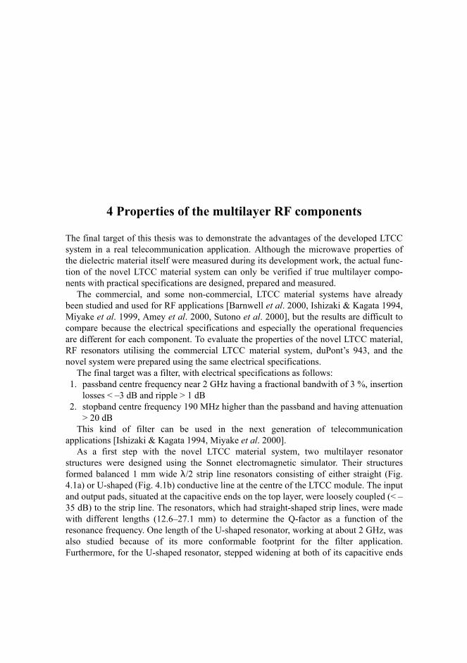
The final target of this thesis was to demonstrate the advantages of the developed LTCCsystem in a real telecommunication application. Although the microwave properties ofthe dielectric material itself were measured during its development work, the actual func-tion of the novel LTCC material system can only be verified if true multilayer compo-nents with practical specifications are designed, prepared and measured.
The commercial, and some non-commercial, LTCC material systems have alreadybeen studied and used for RF applications [Barnwell et al. 2000, Ishizaki & Kagata 1994,Miyake et al. 1999, Amey et al. 2000, Sutono et al. 2000], but the results are difficult tocompare because the electrical specifications and especially the operational frequenciesare different for each component. To evaluate the properties of the novel LTCC material,RF resonators utilising the commercial LTCC material system, duPont’s 943, and thenovel system were prepared using the same electrical specifications.
The final target was a filter, with electrical specifications as follows:1. passband centre frequency near 2 GHz having a fractional bandwith of 3 %, insertion
losses < –3 dB and ripple > 1 dB2. stopband centre frequency 190 MHz higher than the passband and having attenuation
> 20 dBThis kind of filter can be used in the next generation of telecommunication
applications [Ishizaki & Kagata 1994, Miyake et al. 2000].As a first step with the novel LTCC material system, two multilayer resonator
structures were designed using the Sonnet electromagnetic simulator. Their structuresformed balanced 1 mm wide λ/2 strip line resonators consisting of either straight (Fig.4.1a) or U-shaped (Fig. 4.1b) conductive line at the centre of the LTCC module. The inputand output pads, situated at the capacitive ends on the top layer, were loosely coupled (< –35 dB) to the strip line. The resonators, which had straight-shaped strip lines, were madewith different lengths (12.6–27.1 mm) to determine the Q-factor as a function of theresonance frequency. One length of the U-shaped resonator, working at about 2 GHz, wasalso studied because of its more conformable footprint for the filter application.Furthermore, for the U-shaped resonator, stepped widening at both of its capacitive ends

39
was also designed, because this enabled easier coupling arrangements and more suitableimpedance matching. This resonator was thus basically the well-known steppedimpedance resonator.
The values needed for electrical and structural design of the components, the firingprofile and materials used are presented in Tables 4–6 in Chapters 2–3 of this thesis. Inboth cases all outside areas were made uniformly conductive in the co-firing processexcept for the side walls, which were coated using low firing silver-based paste HeraeusDT1402 and post-fired at 600°C. The final thickness of the strip line type resonators was720 µm. [Papers V, VI] Otherwise the preparation followed the common LTCC process.[Ishizaki & Kagata 1994]
(a) (b) (c)Fig. 4.1. Resonators prepared for the Q-factor measurements. a) straight and b) U-shaped λ/2resonators and c) straight λ/4 resonators. [Papers V, VI]
The commercial LTCC material, duPont 943, was also used to study its Q-factor. Thisλ/4 resonator in Fig. 4.1c, the structure of which was the well-known balanced strip linewith a conductive strip at the centre of the LTCC module, was prepared using thefollowing information from the material manufacturer and the commonly describedLTCC process. [Ishizaki & Kagata 1994] The electrical values of this dielectric are inTable 2 (Chapter 2), the firing profile in Table 1 (Chapter 2) and the other parameters inTable 7 (Chapter 3). The designed frequency of the resonators was also near 2 GHz, butthe components were first prepared with meshed grounds, measured and then one upperground was coated with DT1402 paste and post-fired to be uniform. This was done toexclude effects of the ground planes on the electrical performance and also to producesome comparative information. The input and output was arranged as mentioned earlierwith loosely coupled capacitive pads. [Paper V]
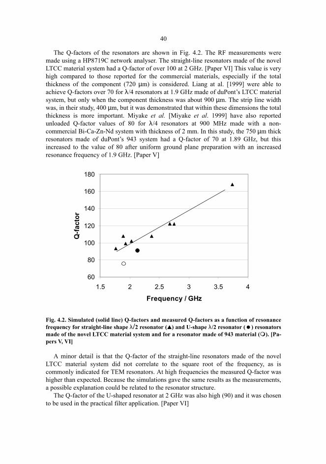
40
The Q-factors of the resonators are shown in Fig. 4.2. The RF measurements weremade using a HP8719C network analyser. The straight-line resonators made of the novelLTCC material system had a Q-factor of over 100 at 2 GHz. [Paper VI] This value is veryhigh compared to those reported for the commercial materials, especially if the totalthickness of the component (720 µm) is considered. Liang at al. [1999] were able toachieve Q-factors over 70 for λ/4 resonators at 1.9 GHz made of duPont’s LTCC materialsystem, but only when the component thickness was about 900 µm. The strip line widthwas, in their study, 400 µm, but it was demonstrated that within these dimensions the totalthickness is more important. Miyake et al. [Miyake et al. 1999] have also reportedunloaded Q-factor values of 80 for λ/4 resonators at 900 MHz made with a non-commercial Bi-Ca-Zn-Nd system with thickness of 2 mm. In this study, the 750 µm thickresonators made of duPont’s 943 system had a Q-factor of 70 at 1.89 GHz, but thisincreased to the value of 80 after uniform ground plane preparation with an increasedresonance frequency of 1.9 GHz. [Paper V]
Fig. 4.2. Simulated (solid line) Q-factors and measured Q-factors as a function of resonancefrequency for straight-line shape λ/2 resonator () and U-shape λ/2 resonator ( ) resonatorsmade of the novel LTCC material system and for a resonator made of 943 material ( ). [Pa-pers V, VI]
A minor detail is that the Q-factor of the straight-line resonators made of the novelLTCC material system did not correlate to the square root of the frequency, as iscommonly indicated for TEM resonators. At high frequencies the measured Q-factor washigher than expected. Because the simulations gave the same results as the measurements,a possible explanation could be related to the resonator structure.
The Q-factor of the U-shaped resonator at 2 GHz was also high (90) and it was chosento be used in the practical filter application. [Paper VI]
60
80
100
120
140
160
180
1.5 2 2.5 3 3.5 4
Frequency / GHz
Q-fa
ctor
41
In conclusion, the results showed that the novel LTCC material system produced atleast 20% higher Q-factors when compared to the resonators made of commercialmaterial with the same component thickness. The basic reasons for these higher Q-factorscould be the lower losses of the dielectric material (0.9⋅10–3 to >1.2⋅10–3) [Bailey et al.1997] and the fact that the λ/2 resonator structures needed no low-conductive grounds atone end of the resonator. This proposed explanation requires further studies.
These U-shaped λ/2 resonators were used in the designed filter structures. Theequivalent circuit diagram of the filter is shown in Fig. 4.3.
Fig. 4.3. The equivalent circuit diagram of bandpass filter using the novel LTCC materialsystem. [Paper VI]
The filter comprised a bandpass structure (Fig. 4.3) with two resonators (R1 and R2),capacitive inputs and outputs (Cin and Cout) and an excess notch (Lcoup) improving thestop band attenuation. The coupling between the resonators was arranged using acapacitance (Ccoup). [Paper VI]
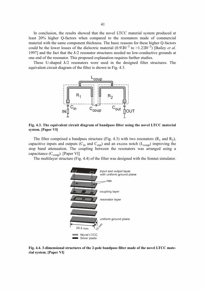
The multilayer structure (Fig. 4.4) of the filter was designed with the Sonnet simulator.
Fig. 4.4. 3-dimensional structures of the 2-pole bandpass filter made of the novel LTCC mate-rial system. [Paper VI]
vias

42
The resonators (R1 and R2) were situated in the middle of the multilayer LTCC moduleand the same layer included the notch-forming transmission line (Lcoup). The couplingpads (Cin and Cout) were located on the coupling layer with the capacitive input andoutput pads connected through vias to the terminals of the top layer. The thickness of thestructure was the same as for the measured U-shaped resonator as were the preparationand structural routes and values for the electrical design. [Paper VI]
The simulated and measured frequency responses of the filter are shown in Fig. 4.5.
(a) (b)Fig. 4.5. The simulated (a) and measured (b) frequency response of the prepared filter (… S11,— S21) indicating desired bandwidths and attenuation (—). [Paper VI]
The prepared filter had insertion loss in the pass band <–2dB, the ripple was < 1 dBand the attenuation losses in the stopband were more than 25 dB, indicating its superiorproperties. The difference between the simulated and measured centre frequency valueswas about 30 MHz and the bandwidth was somewhat narrower. The cause of thesedeviations was inaccurate positioning of the coupling layer identified by scanningacoustic microscope. [Paper VI] Furthermore, the measured filter had a very highreflection attenuation, which is caused by its double tuned response. This was not foundwith the Sonnet electromagnetic simulator because the program version used was not ableto optimise.
In Paper V, a bandstop filter with two λ/4 resonators and the same capacitive couplingsystem but using duPont’s 943 materials was also prepared. Although it is difficult tocompare the properties of different types of filters, a rough comparison of their frequencyresponses suggests that the same kind of superior properties of this novel LTCC materialsystem may be obtained in a filter as were measured for separate resonators. This studydemonstrated that the novel LTCC material system can successfully be used for RF filtersfor the next generation of telecommunication applications. Further improvements andtests are needed for larger manufacturing.

5 Conclusions
The main target of this thesis has been to develop a novel LTCC dielectric material suit-able for microwave and RF telecommunication applications. The two most importantresearch objectives were the development of the dielectric ceramic and its preparationprocedure for multilayer components. Also its properties were demonstrated with RF res-onators operating in the frequency range between 1.8 and 3.8 GHz and a filter at 2 GHz.
The basic characteristics of a novel LTCC material are set by requirements of the finalcomponents. Special attention has to be paid to the values of the permittivity, εr, thedissipation factor, DF, and the temperature coefficient of the resonance frequency, τf. Allthese electrical material properties are very important for microwave devices. Thepermittivity should conform to the process and application demands and limitations, lowlosses are always desired and the RF components have to give the same frequencyresponse at all operational temperatures. The first two properties have been well reported,but the importance of the temperature stability of the resonance frequency has receivedonly very limited attention. The commercial LTCC materials, for example, have the εrbetween 4–10 and the measured DF > 1.2⋅10–3, but the values of τf are not normallypublished.
Although the dielectric properties are essential, the LTCC process itself hasfundamental requirements for the dielectric material. First of all the ceramic compositionshould reach it full density in a low temperature firing process which includes completeburn-out of the organic additives used in tape casting. The tape should also have a smoothsurface, it should be self supporting, easy to laminate and be compatible with a low firing,high conductive paste. Only these properties can assure that real multilayer componentscan be produced. Additionally, the thermomechanical properties of the dielectric materialshould enable the use of the prepared components with high reliability.
In this thesis all these requirements have been taken into account. The basic study hasbeen done with the development of the dielectric material by decreasing the firingtemperature of MgCaTiO3 dielectric, through the addition of ZnO-SiO2-B2O3, from1360oC to 900oC. The firing and microstructure properties of the composition wereinvestigated using the dilatometer, SEM/EDS and XRD. The dielectric properties werestudied with the Hakki-Coleman method and coaxial resonators and finally, the most

44
critical thermomechanical values, linear thermal expansivity, elastic modulus, hardness,fracture strength and toughness, were determined. The results were compare to thecorresponding properties of the commercial LTCCs.
The tape casting and multilayer component preparation procedures were studied withthe selection of a suitable silver-based paste for the conductors. Finally, multilayerresonators and a bandpass filter were prepared using this novel LTCC material system andprocess, both introduced in this thesis.
The most important results of the thesis were as follows:1. The novel dielectric LTCC made of the MgCaTiO3 and ZnO-SiO2-B2O3 can be
prepared without any prior glass preparation route, which makes the powder processvery straightforward and minimises the risk of component volatilisation.
2. The fired microstructure was dense with a low porosity composed of totallycrystalline phases, which improved the dielectric and thermomechanical properties ofthe material.
3. The DF of the novel dielectric was lower (0.9⋅10–3 at 8 GHz) when compared to thecommercial LTCCs and, furthermore, the value of the τf is shown to be adjustablewith the amount of TiO2 in the composition. The permittivity was 8.5.
4. The mechanical properties of the dielectric were almost the same as for thecommercial LTCCs, but this material had a higher thermal expansivity (8.5 ppm K–1)and is thus especially compatible with alumina substrates.
5. In the tape casting procedure, the common slurry preparation method and additivescould be used and the final green tape had a smooth surface and good lamination andfiring properties. Additionally, a commercial low resistive silver paste could be usedwith this LTCC to form the inner and outer conductors and via filling needed formultilayer components.
The studies described in this thesis are fundamental investigations of the developmentof novel LTCC materials systems. The achieved state of the art offers an opportunity toprepare RF and microwave components with excellent properties in small scaleproduction. The results also compare well with the state of prior art of commercial LTCCdielectrics and in many ways even exceed this. For large scale production however,further work needs to be done.

References
Abe M, Nanataki T & Yano S (1996) Dielectric Ceramic Composition Containing ZnO-B2O3-SiO2Glass, Method of Preparing the same, and Resonator and Filter using the Dielectric Ceramic Com-position. US patent 5.493.262.
Alford N McN, Penn SJ, Templeton A, Wang X, Gallop JC, Klein N, Zuccaro C & Filhol P (1997)Microwave Dielectrics. Proc. IEE Colloquium on Electro-technical Ceramics – Processing, Prop-erties and Applications (Ref. No.: 1997/317), London, UK, 9:1-5.
Amey DI, Keating MY, Smith MA, Horowitz SJ, Donahue PC & Needes CR (2000) Low Loss TapeMaterials System for 10 to 40 GHz Application. Proc. International Symposium on Microelec-tronics, IMAPS, Boston, MA, USA, 654–658.
Baesso ML, Bento AC, Duarte AR, Neto AM, Miranda LCM, Sampaio JA, Catunda T, Gama S &Gandra FCG (1999) Nd2O3 Doped Low Silica Calsium Aluminosilicate Glasses: Thermomechan-ical Properties. Journal of Applied Physics, 85(12): 8112–8118.
Bailey A, Foley W, Hageman M, Murrey C, Piloto A, Sparks K & Zaki K (1997) Miniature LTCCFilters for Digital Receivers. Proc. IEE MTT-S International Microwave Symposium Digest, Den-ver, Co, USA, 2: 999–1002.
Barnwell P, Zhang W, Lebowitz J, Jones K, MacDonald N, Free C & Tian Z (2000) An Investigationof the Properties of LTCC Materials and Compatible Conductors for their use in Wireless Appli-cations. Proc. International Symposium on Microelectronics, IMAPS, Boston, MA, USA, 659–664.
Berry C, Parlow D, Vasilow T, Gurkovich S & Bailey A (2000) A Design of Experiment for a TapeCasting Process. Proc. International Symposium on Microelectronics, IMAPS, Boston, MA,USA, 150–155.
Bever MB (1986) Encyclopedia of Materials Science and Engineering, Vol. 1. Pergamon Press. p155.
Cahn RW, Haasen P & Kramer EJ (1996) Materials Science and Technology. Vol. 17A: Processingof Ceramics (Vol. Ed. Brook RJ). VCH Verlagsgesellschaft mbH. Chap. 7.
Canumalla S & Oravecz MG (1997) Nondestructive Elastic Property Characterization of IC Encap-sulants. Proc. ASME WAM Symposium on Applications of Fracture Mechanics in ElectronicPackaging, Dallas, TX, USA, 25–32.
Dakeya Y, Suesada T, Asakura K, Nakajima N & Mandai H (2000) Chip Multilayer Antenna for 2.45GHz-Band Application Using LTCC Technology. Proc. IEEE MMT-S International MicrowaveSymposium Digest, Boston, MA, USA, 3: 1693–1696.

46
Donahue PC, Taylor BE, Amey DI, Draudt RR, Smith MA, Horowitz SJ & Larry JR (1998) A NewLow Loss Lead Free LTCC System for Wireless and RF Applications. Proc. International Confer-ence on Multichip Modules and High Density Packaging, IEEE, New York, USA, 196–199.
Dube DC, Zurmuhlen R, Bell A, Setter N & Wersing W (1997) Dielectric Measurements on High-QCeramics in the Microwave Region. Journal of American Ceramic Society, 80(5): 1095–1100.
Feng J-H & Dogan F (2000) Effects of Solvent Mixtures on Dispersion of Lanthanum-Modified LeadZirconate Titanate Tape Casting Slurries. Journal of American Ceramic Society, 83(7): 1681–11686.
Fujishima S (2000) The History of Ceramic Filters. IEEE Transactions on Ultrasonics, Ferroelectricsand Freqency Control, 47(1): 1–7.
Gektin V, Bar-Cohen A & Witzman S (1998) Coffin-Manson Based Fatigue Analysis of UnderfilledDCAs. IEEE Transactions on Components, Packaging and Manufacturing Technology-Part A,21(4): 577–584.
Hakki BW & Coleman PD (1960) Dielectric Resonator Method of Measuring Inductive Capacitiesin the Millimeter Range. IRE Transactions on Microwave Theory and Techniques, MTT-8: 402–410.
Hing P & McMillan PW (1973) The Strength and Fracture Properties of Glass-Ceramics, Journal ofMaterial Science, 8(7): 1041–1048.
Howatt GN, Breckenridge RG & Brownlow JM (1947) Fabrication of Thin Ceramic Sheets for Ca-pacitors. Journal of American Ceramic Society, 30(8): 237–242.
Huang C-Y & Lin M-H (2000) Ceramic GPS Antenna for Remote Sensing. International Geoscienceand Remote Sensing Symposium, IEEE, Piscataway, NJ, USA, 5: 2182–2184.
Hunter IC & Walker V (2000) Ceramic Filters in Mobile Communications. Proc. IEE Colloquium onMicrowave Filters and Multiplexers (Ref. No. 2000/117), London, UK, 5:1-3.
Izhizaki T & Kagata H (1994) A Very Small Dielectric Planar Filter for Portable Telephones. IEEETransactions on Microwave Theory and Techniques, 42(11): 2017–2022.
Jantunen H. & Turunen A (1994) Temperature Compensated Dielectric Filter. US patent 5.302.924.Jean J-H & Gupta TK (1994) Design of Low Dielectric Glass+Ceramics for Multilayer Ceramic Sun-
strate. IEEE Transactions on Components, Packaging and Manufacturing Technology-Part B: Ad-vanced Packaging, 17(2): 228–233.
Jones WK, Liu Y, Larsen B, Wang P & Zampino M (2000) Chemical, Structural and MechanicalProperties of the LTCC Tapes. Proc. International Symposiumon Microelectronics, IMAPS, Bos-ton, MA, USA, 669–704.
Kagata H, Inoue T, Kato J & Kameyama I (1992) Low-Fired Bismuth-Based Dielectric Ceramics forMicrowave Use. Japanese Journal of Applied Physics, Part 1,31(9B): 3152–3155.
Katoh T & Ozeki H (1994) Microwave Dielectric Ceramic Composition. US patent 5.340.784.Kemppinen E & Leppävuori S (1986) Coaxial Resonator Method to Detemine Dielectric Properties
of High Dielectric Constant Microwave Ceramics. International Journal of High Technology Ce-ramics, 2: 143–155.
Kim HT, Kim SH, Nahm S, Byun JD & Kim Y (1999) Low-Temperature Sintering and MicrowaveDielectric Properties of Zinc Metatitanate-Rutile Mixtures Using Boron. Journal of American Ce-ramic Society, 82(11): 3043–3048.
Kingery WD, Bowen HK & Uhlman D R (1976) Introduction to Ceramics, 2nd ed. John Wiley &Sons, p 787, 828, 940.
Kniajer G, Dechant K & Apté P (1997) Low Loss, Low Temperature Cofired Ceramics with HigherDielectric Constants for Microchip Modules (MCM). Proc. International Conference on MultichipModules, IEEE, New York, USA, 121–127.
Knickerbocker SH, Kumar AH & Herron LW (1993) Cordierite Glass-Ceramics for Multilayer Ce-ramic Packaging, American Ceramic Society Bulletin, 72(1): 90–95.

47
Kobayashi Y & Katoh M (1985) Microwave Measurement of Dielectric Properties of Low Loss Ma-terials by the Dielectric Rod Resonator Method. IEEE Transanctions on Microwave Theory andTechniques, MTT-33(7): 586–592.
Liang H, Sutono A, Lasker J & Smith WR (1999) Material Parameter Characterization of MultilayerLTCC and Implementation of High Q Resonators. Proc. IEEE MMT-S International MicrowaveSymposium Digest, Anaheim, CA, USA, 4: 1901–1904.
Ludwig R & Bretchko P (2000) RF Circuit Design. Prentice-Hall, p 65 p.Mattox DM, Gurkovich SR, Olenick JA & Mason KM (1988) Low Dielectric Constant, Alumina-
Compatible Co-Fired Multilayer Substrate. Ceramic Engineering and Science Proceedings, 9:1567–1578.
McMillan PW (1979) Glass-Ceramics. Academic Press, p 184, 209.Miyake H, Kitazawa S, Ishizaki T, Ogawa K & Awai I (1999) A Study of a Laminated Band Elimi-
nation Filter Comprising Coupled-Line Resonators Using Low Temperature Co-Fired Ceramic.IEICE Transactions on Electronics, E82-C(7): 1104–1109.
Miyake H, Kitazawa S, Ishizaki T, Tsuchuyama M, Ogawa K & Awai I (2000) A New Circuit Con-figuration to Obtain Large Attenuation with a Coupled-Resonator Band Elimination Filter usingLaminated LTCC. Proc. IEEE MMT-S International Microwave Symposium Digest, Boston,MA, USA, 1: 195–198.
Mizoe J, Amano S, Kuwabara T, Kaneko T, Wada K, Kato A, Sato K & Fujise M (1999) Miniature60 GHz Transmitter/Receiver Modules on AlN Multilayer High Temperature Co-Fired Ceramic.Proc. IEEE MMT-S International Microwave Symposium Digest, Anaheim, CA, USA, 2: 475–478.
Nufer RW (1992) Ceramic Greensheet Technology for Glass-Ceramic/Copper Multilayer Substrate(ES9000 System). Proc. 42rd Electronic Components and Technology Conference (ECTC), IEEE,Piscataway, NJ, USA, 673–677.
Penn SJ, Alford N McN, Templeton A, Klein N, Gallop JC, Filhol P & Wang X (1997) Low LossCeramic Dielectrics for Microwave Filters. Proc. IEE Colloquium on Advanced in Passive Micro-wave Components (Digest No.: 1997/154), London, UK, 6: 1-6.
Scrantom CQ & Gravier GJ (1999) LTCC Technology: Where we are and where we’re going – IV.Proc. IEEE MTT-S International Topical Symposium on Technologies for Wireless ApplicationsDigest, Vancouver, Bc., Canada, 193–200.
Sheen J-W (1999) LTCC-MLC Deplexer for DCS-1800. IEEE Transactions on Microwave Theoryand Techniques, 47(9): 1883–1890.
Shutler W, Longworth H, Pennacchia J, Perfecto E & Shields R (1997) A Family of High Perform-ance MCM-C/D Packages Utilizing Cofired Alumina Multilayer Ceramic and a Shielded ThinFilm Redistribution Structure. International Journal of Microcircuits and Electronic Packaging,20(3): 289–296.
Su B & Button TW (2000) Interactions between Barium Strontium Titanate (BST) Thick Films andAlumina Substrates. Presented at the Microwave Materials and their Applications Conference(MMA2000), Bled, Slovenia, 1–11.
Sung Y-M & Kim S (1999) Mechanical Properties of Off-stochiometric BaO.Al2O3.2SiO3 Glass-Ce-
ramics. Journal of Material Science Letters, 18: 1657–1660.Sutono A, Laskar J & Smith WR (2000) Development of Integrated Three Dimensional Bluetooth
Image Reject Filter. IEEE MMT-S International Microwave Symposium Digest, Boston, Ma,USA, 1: 339–342.
Szafran M & Rokicki G (2001) Effect of Acrylic-Styrene Copolymer Chemical Structure on the Prop-erties of Ceramic Tapes Obtained by Tape Casting. Journal of American Ceramic Society, 84(6):1231–1235.

48
Tagami K, Kubo T, Makihara C, Tanahashi S, Emura H, Tanaka J, Sueyoshi T & Kunimatsu Y (1997)Glass Ceramics Functional Substrate Development. Proc. International Conference on MicrochipModules, IEEE, New York, USA, 363–370.
Thust H, Drüe KH, Müller J, Thelemann T, Tuschick T, Chilo J, Golovanov C & Ndagijimana F(1998) Coupling Behavior between Transmission Lines with Meshed Ground Planes in LTCC-MCMs. Microwave Journal, 41(11): 70–79.
Tummala RR (1991) Ceramic and Glass-Ceramic Packaging in the 1990s. Journal of American Ce-ramic Society, 74(5): 895–908.
Wakino K, Nishikawa T, Tamura H & Sudo T (1987) Dielectric Resonator Materials and their Ap-plications. Microwave Journal, 30(6): 133–159.
Wang C & Zaki KA (1999) Temperature Compensation of Combline Resonators and Filters. Proc.IEEE MMT-S International Microwave Symposium Digest, Anaheim, CA, USA, 3: 1041–1044.
Woo DC, Lee HY, Kim J-J, Kim T H, Lee SJ, Park JR & Choy TG (1996) Microwave DielectricProperties of Doped-MgTiO3 Ceramics. Proc. Tenth IEEE International Symposium on Applica-tions of Ferroelectrics, ISAF’96, New York, USA, 2: 863–866.

Original papers