A New Orthotropic BRIDGE DECK: Design, Fabrication...
22
A New Orthotropic BRIDGE DECK: Design, Fabrication and Construction of the Shenley Bridge Incorporating an SPS Orthotropic Bridge Deck by Richard B. Vincent 1 and Angelo Ferro 2 Key Words: orthotropic, steel, bridge, decks, prefabrication, construction, speed 1.0 Introduction to SPS The Structal Division of The Canam Manac Group Inc. has constructed the first steel bridge utilizing an orthotropic steel deck that incorporates the Sandwich Plate System (SPS) technology. The SPS orthotropic bridge deck was supplied and fabricated by the Solicor Division of The Canam Manac Group Inc. Intelligent Engineering (IE) has developed and patented the Sandwich Plate System, in which two metal plates are bonded to a solid elastomer core. The elastomer provides continuous support to the plates and precludes local plate buckling and minimizes the need for stiffeners. The flexural stiffness and strength of the sandwich plate is tailored to meet particular static and dynamic structural requirements by selecting appropriate thickness for each sandwich element. SPS replaces conventional stiffened metal plates in maritime, offshore and civil engineering structures. SPS provides benefits in fabrication, performance, cost and safety for both civilian and military applications. The SPS technology was developed over an ten-year period with the guidance of regulator’s such as Lloyd’s Register and in close collaboration with BASF AG. Physical properties, design parameters and production techniques have been established through extensive analytical, experimental and prototype work. Fabrication and performance benefits of SPS construction stem from structural simplification and the properties of the composite material. These include: fewer parts, less welding, reduced weight, reduced surface area, built-in structural fire protection, thermal and acoustic insulation and better dimensional accuracy. Fewer corrosion and fatigue prone details and improved vibration damping lead to increased service life. Safety and environmental benefits of SPS stem from increased capacity to absorb energy and crack arrest properties that improve fatigue performance and reduce the effects of accidental or extreme loads. Economic benefits of SPS include scope for reducing new build construction costs and significant operating cost savings over the life of the structure. SPS is also used for repair and conversion purposes as SPS Overlay. SPS Overlay bonds a new top plate to the existing structure in a process that is simple, safe, non-disruptive and very fast. Richard B. Vincent, Vice President Engineering, Research and Development, The Canam Manac Group Inc., 270 Chemin du Tremblay, Boucherville, QC, J4B 5X9. Tel.: 450-641-4000; Fax.: 450-641-4001; [email protected] Angelo Ferro, Structural Engineer, Intelligent Engineering (Canada) Limited, 72 Chamberlain Avenue, Ottawa, ON, K1S 1V9. Tel.: 613-569-3111; Fax.: 613-569-3222; [email protected]
-
Upload
phunghuong -
Category
Documents
-
view
217 -
download
0
Transcript of A New Orthotropic BRIDGE DECK: Design, Fabrication...

A New Orthotropic BRIDGE DECK: Design, Fabrication and Construction of the Shenley Bridge
Incorporating an SPS Orthotropic Bridge Deck by Richard B. Vincent1 and Angelo Ferro2
Key Words: orthotropic, steel, bridge, decks, prefabrication, construction, speed 1.0 Introduction to SPS The Structal Division of The Canam Manac Group Inc. has constructed the first steel bridge utilizing an orthotropic steel deck that incorporates the Sandwich Plate System (SPS) technology. The SPS orthotropic bridge deck was supplied and fabricated by the Solicor Division of The Canam Manac Group Inc. Intelligent Engineering (IE) has developed and patented the Sandwich Plate System, in which two metal plates are bonded to a solid elastomer core. The elastomer provides continuous support to the plates and precludes local plate buckling and minimizes the need for stiffeners. The flexural stiffness and strength of the sandwich plate is tailored to meet particular static and dynamic structural requirements by selecting appropriate thickness for each sandwich element. SPS replaces conventional stiffened metal plates in maritime, offshore and civil engineering structures. SPS provides benefits in fabrication, performance, cost and safety for both civilian and military applications. The SPS technology was developed over an ten-year period with the guidance of regulator’s such as Lloyd’s Register and in close collaboration with BASF AG. Physical properties, design parameters and production techniques have been established through extensive analytical, experimental and prototype work. Fabrication and performance benefits of SPS construction stem from structural simplification and the properties of the composite material. These include: fewer parts, less welding, reduced weight, reduced surface area, built-in structural fire protection, thermal and acoustic insulation and better dimensional accuracy. Fewer corrosion and fatigue prone details and improved vibration damping lead to increased service life. Safety and environmental benefits of SPS stem from increased capacity to absorb energy and crack arrest properties that improve fatigue performance and reduce the effects of accidental or extreme loads. Economic benefits of SPS include scope for reducing new build construction costs and significant operating cost savings over the life of the structure. SPS is also used for repair and conversion purposes as SPS Overlay. SPS Overlay bonds a new top plate to the existing structure in a process that is simple, safe, non-disruptive and very fast. Richard B. Vincent, Vice President Engineering, Research and Development, The Canam Manac Group Inc., 270 Chemin du Tremblay, Boucherville, QC, J4B 5X9. Tel.: 450-641-4000; Fax.: 450-641-4001; [email protected] Angelo Ferro, Structural Engineer, Intelligent Engineering (Canada) Limited, 72 Chamberlain Avenue, Ottawa, ON, K1S 1V9. Tel.: 613-569-3111; Fax.: 613-569-3222; [email protected]
2
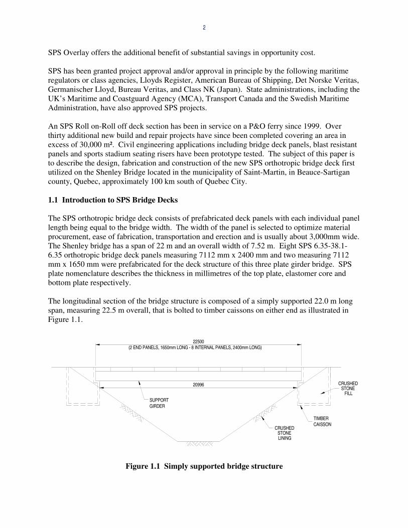
SPS Overlay offers the additional benefit of substantial savings in opportunity cost. SPS has been granted project approval and/or approval in principle by the following maritime regulators or class agencies, Lloyds Register, American Bureau of Shipping, Det Norske Veritas, Germanischer Lloyd, Bureau Veritas, and Class NK (Japan). State administrations, including the UK’s Maritime and Coastguard Agency (MCA), Transport Canada and the Swedish Maritime Administration, have also approved SPS projects. An SPS Roll on-Roll off deck section has been in service on a P&O ferry since 1999. Over thirty additional new build and repair projects have since been completed covering an area in excess of 30,000 m². Civil engineering applications including bridge deck panels, blast resistant panels and sports stadium seating risers have been prototype tested. The subject of this paper is to describe the design, fabrication and construction of the new SPS orthotropic bridge deck first utilized on the Shenley Bridge located in the municipality of Saint-Martin, in Beauce-Sartigan county, Quebec, approximately 100 km south of Quebec City. 1.1 Introduction to SPS Bridge Decks The SPS orthotropic bridge deck consists of prefabricated deck panels with each individual panel length being equal to the bridge width. The width of the panel is selected to optimize material procurement, ease of fabrication, transportation and erection and is usually about 3,000mm wide. The Shenley bridge has a span of 22 m and an overall width of 7.52 m. Eight SPS 6.35-38.1-6.35 orthotropic bridge deck panels measuring 7112 mm x 2400 mm and two measuring 7112 mm x 1650 mm were prefabricated for the deck structure of this three plate girder bridge. SPS plate nomenclature describes the thickness in millimetres of the top plate, elastomer core and bottom plate respectively. The longitudinal section of the bridge structure is composed of a simply supported 22.0 m long span, measuring 22.5 m overall, that is bolted to timber caissons on either end as illustrated in Figure 1.1.
20996
SUPPORTGIRDER
TIMBERCAISSON
(2 END PANELS, 1650mm LONG - 8 INTERNAL PANELS, 2400mm LONG)
CRUSHEDSTONE
FILL
LININGSTONE
CRUSHED
22500
Figure 1.1 Simply supported bridge structure

3
Figure 1.2 is a schematic view of a section of the bridge structure illustrating the transversely oriented SPS 6.35-38.1-6.35 deck panels. Prefabrication of the SPS plates facilitates stricter quality control and rapid on-site assembly of the deck structure. Fewer fatigue prone details and improved vibration damping of the SPS deck plate system, which is exposed to heavy truck traffic, lead to an increased service life.
Figure 1.2 Schematic view of bridge structure with transversely oriented SPS plates The SPS bridge panel is designed to span between the main girders and cantilevers over the edge girders to support the curb and traffic barrier. The longitudinal edges of the panels are framed with bent plates that act as cross stringers. Hot rolled angles could also be used to act as cross stringers, but the available range of angle sizes is limited. The cross stringers, together with the SPS plate acting as the top flange, create a very stiff section that permits the panel to be designed for large cantilever spans. In the case of the Shenley bridge, the deck cantilever beyond the perimeter girder is only 806 mm. Figure 1.3 (a) shows a plan view of the Shenley bridge panel and Section D-D that is a longitudinal section through the panel. Figure 1.3 (b) displays three different sections of the panel, Section A-A taken at the lateral web member, Section B-B taken through the SPS plate and Section C-C taken beyond the exterior edge of the panel. An important feature of the SPS deck panel is that it is designed to act compositely with the main girders. Horizontal shear is transferred through deck panel web sections parallel to the main girders and located directly over the webs of the bridge girders. The web sections are fabricated from either hot rolled angles, bent plate angles or tee sections that are two sided fillet welded to the underside of the SPS plate. The flange of the web sections are field bolted directly to the top
Typical SPS Deck Panel

4
flanges of the main girder designed as a slip-critical connection using pretensioned high strength bolts. Oversized holes are used in either the girder or bent angle to facilitate erection. Figure 1.4, Section E-E illustrates the attachment of the web section to the bottom plate of the SPS sandwich and the connection of the web section to the girder flange. The ends of the web section are shop welded to the cross stringer as shown in Figure 1.4, Detail “F”. Adjacent SPS deck panels need to be interconnected to achieve continuous composite action with the bridge girders. This continuity also serves to reduce deflections resulting from wheel loads on the 3.0 m span for the SPS plate between cross stringers. Continuity of the bottom plate of the SPS panel is assured by bolting the deck panels together just below the SPS plate (see Figure 4.1). The spacing of the bolts is selected to transfer any shear between panels as well as the tensile or compressive forces in the SPS plate due to flexural bending forces of the plate acting compositely with the girder and the local bending forces due to wheel loading. The continuity of the top plate of the SPS plate is achieved via a field welded partial penetration groove weld. The groove weld runs along the top of the adjacent cross stringer angles that are prepared to the appropriate bevel (see Figure 4.1). The depth and geometry of the weld is determined to resist the bending forces in the top plate resulting again from composite action and wheel loads and to achieve the desired fatigue resistance.
Figure 1.3 (a) Plan View and Longitudinal Section of the SPS bridge deck

5
Figure 1.3 (b) SPS bridge deck – Sections Fabrication tolerances are very important as the number of deck panels increase with the span of the bridge and any variation in the width of a panel will quickly accumulate into an error larger than can be accommodated by the oversize holes. Deck panel sections are shop fabricated to a tolerance of + 0 mm and – 3 mm. Thus any accumulation of fabrication errors in the field will lead to an loss in panel length along the bridge that can be remedied by incorporating a filler plate between panels on site as required. The SPS orthotropic deck panel has been designed to facilitate connections for the barriers, curbs and other attachments such as kilometre markers, signage and light standards. The ends of the deck panel are capped with a closure or end plate that can extend beyond the top of the SPS plate to act as a support and stopper for the asphalt or other wearing surface, see Figure 1.4, Section G-G. Barriers are bolted directly to this closure plate. The spacing of the barrier posts are designed to coincide with the deck panel splices so that the barrier connection is shared between two adjacent panels. The end or closure plate is welded to and stiffened by the cross stringer. The bottom edge of the closure plate is also stiffened by a horizontal end plate stiffener that spans from cross stringer to cross stringer, see Figure 1.4, Section H-H. The thickness of the closure plate, stiffener plate and spacing of bolts for the barrier post are all determined by the Performance Level for the specified traffic barrier. The barrier selected for the Shenley bridge was an existing design used by the State of Arizona that had previously been crash tested on concrete curbs. The design was modified by replacing the anchor bolts in the concrete curb with equivalent strength high strength bolts attached to the SPS deck panel. The closure plate and stiffener plate thickness were designed to resist the maximum high strength bolt forces.

6
Figure 1.4 SPS bridge deck – Sections Connections for signage can be incorporated into the design concept and shop connections fabricated to receive these elements. Future signage requirements can usually be accommodated by simply field drilling the appropriate holes necessary for the attachment. Stiffening plates that may be required to accommodate these special attachments can be field welded to stiffen the closure plate as required. The last important design feature of the SPS orthotropic bridge deck is its long life. The Canadian Highway Bridge Design Code specifies that the design life of a new structure is to be 75 years. The deck panel is fabricated from atmospheric corrosion resistant steel such as CSA G40.21 type 350A or 350AT if notch toughness is desired. These grades of steel will easily
7
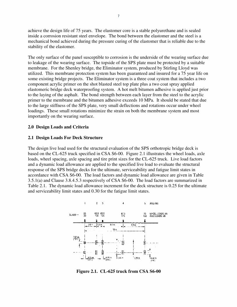
achieve the design life of 75 years. The elastomer core is a stable polyurethane and is sealed inside a corrosion resistant steel envelope. The bond between the elastomer and the steel is a mechanical bond achieved during the pressure curing of the elastomer that is reliable due to the stability of the elastomer. The only surface of the panel susceptible to corrosion is the underside of the wearing surface due to leakage of the wearing surface. The topside of the SPS plate must be protected by a suitable membrane. For the Shenley bridge, the Eliminator system, produced by Stirling Lloyd was utilized. This membrane protection system has been guaranteed and insured for a 75 year life on some existing bridge projects. The Eliminator system is a three coat system that includes a two component acrylic primer on the shot blasted steel top plate plus a two coat spray applied elastomeric bridge deck waterproofing system. A hot melt bitumen adhesive is applied just prior to the laying of the asphalt. The bond strength between each layer from the steel to the acrylic primer to the membrane and the bitumen adhesive exceeds 10 MPa. It should be stated that due to the large stiffness of the SPS plate, very small deflections and rotations occur under wheel loadings. These small rotations minimize the strain on both the membrane system and most importantly on the wearing surface. 2.0 Design Loads and Criteria 2.1 Design Loads For Deck Structure The design live load used for the structural evaluation of the SPS orthotropic bridge deck is based on the CL-625 truck specified in CSA S6-00. Figure 2.1 illustrates the wheel loads, axle loads, wheel spacing, axle spacing and tire print sizes for the CL-625 truck. Live load factors and a dynamic load allowance are applied to the specified live load to evaluate the structural response of the SPS bridge decks for the ultimate, serviceability and fatigue limit states in accordance with CSA S6-00. The load factors and dynamic load allowance are given in Table 3.5.1(a) and Clause 3.8.4.5.3 respectively of CSA S6-00. The load factors are summarized in Table 2.1. The dynamic load allowance increment for the deck structure is 0.25 for the ultimate and serviceability limit states and 0.30 for the fatigue limit states.
Figure 2.1. CL-625 truck from CSA S6-00

8
Table 2.1. CSA S6-00 Load factors
Load factor Ultimate limit states
Serviceability limit states
Fatigue limit state
Live load 1.70 0.90 1.00a Dead load see note (b) 1.00 NA
(a) a calibration factor of 0.62 is applied to the calculated stress range due to the CL 625 truck tandem axles as per section 10.17.2.2 of CAN/CSA-S6-00
(b) for factory produced components αD = 1.10, for wearing surfaces αD = 1.50, for wood and non-structural components αD = 1.20
(a) Load Case A
22500 (2 @ 1650 & 8 @ 2400)
TIRE PRINT600 x 250
TIRE PRINT250 x 250
12003600
2750
2750
806
806
7112
6006006600
(175 KN)AXLE 4AXLE 3
(125 KN)(125 KN)AXLE 2AXLE 1
(50 KN)
900
900
406
5250
(b) Load Case B 40
6
900
900
(50 KN)AXLE 1 AXLE 2
(125 KN) (125 KN)AXLE 3 AXLE 4
(175 KN)
66001800 1800
7112
806
806
2750
2750
3600 1200
TIRE PRINT250 x 250
TIRE PRINT600 x 250
22500 (2 @ 1650 & 8 @ 2400)
600
4050
(c) Load Case C
5645 5455
600
22500 (2 @ 1650 & 8 @ 2400)
TIRE PRINT600 x 250
TIRE PRINT250 x 250
12003600
2750
2750
806
806
7112
8053956600
(175 KN)AXLE 4AXLE 3
(125 KN)(125 KN)AXLE 2AXLE 1
(50 KN)
900
900
406
Figure 2.2 Load Cases

9
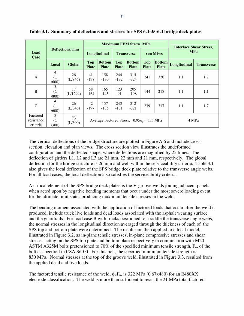
To determine the structural response of the SPS bridge deck plates, two design trucks are positioned to produce the maximum load effect. Figure 2.2 illustrates the three load cases considered with tire print sizes, locations and orientations indicated on the figure. In load case A, truck Axles 2 and 3 are positioned directly between transverse angle webs. In load case B, truck Axles 2 and 3 straddle the transverse angle web. In load case C, the tires are located on the bridge deck to produce the maximum global moment. 2.2 Design criteria The factored resistance based on CSA S6-00 and compared to finite element analysis results, is presented here. The factored member resistances given in the code for members in flexure and tension is based on 0.95 of the yield stress, 0.95�y. For members in compression, the stress is limited to 0.90�y when buckling is not a consideration. The deflection due to live loads for the serviceability limit state is limited to 1/300 of the span. For the fatigue limit state, the fatigue stress range due to a pair of tandem axles is not to exceed the fatigue stress range resistance for details subject to load-induced fatigue in bridge decks. 3.0 Strength Evaluation 3.1 Finite Element Model The finite element model for the SPS 6.4-35-6.4 bridge deck plates, that includes the three supporting girders as is illustrated in Figure 3.1 for load case A, presents the boundary conditions, analysis options and loadings considered to determine the structural response of the SPS bridge deck plates. The tire print dimensions, orientation, spacing, and loads for the two design trucks as applied to the finite element model are summarized in Figure 2.2. 3.2 Analytical Results Table 3.1 provides a summary of the deflections and stresses on the SPS bridge deck plate for serviceability and ultimate limit states. It should be noted that the stresses included in Table 3.1 are maximum peak stresses from the finite element model and have not been averaged over the element surface. The deflections and stresses for load cases A and B were determined based on the finite element model given in Figure 3.1 of the simply supported bridge structure including the three supporting girders with the trucks positioned as illustrated in Figure 2.2(a) and (b). The deflections and stresses for load case C were determined based on the trucks positioned to produce the maximum global moment as illustrated in Figure 2.2(c). Vertical deflection, principal normal stresses, von Mises stresses and interface shear stresses are plotted in Figures A.1 to A.6 of Appendix A for load case A, where the maximum values and their locations are identified. Figures A.1 to A.3 illustrate the FEM maximum longitudinal, transverse and von Mises stresses in the top and bottom faceplates of the SPS prefabricated bridge deck plates. For tire prints positioned adjacent to the webs of longitudinal and transverse angles, the normal and von Mises stresses tend to be highly localized in the plating over the webs and dissipate rapidly. For all load cases the stresses satisfy the factored resistance criteria.

10
The maximum interface shear stresses between the steel faceplates and elastomer in the longitudinal and transverse directions are illustrated in Figure A.4 for load case A. All stresses were less than 2 MPa and well within the factored resistance criteria of 4 MPa. Figure A.5 illustrates the normal stress in the longitudinal direction for both the top and bottom flanges of the supporting girders. The average tensile stress across the bottom flange width in the longitudinal direction for the center girder, L2, is 150 MPa. The average compressive stress across the top flange width in the longitudinal direction for the center girder is 18 MPa. The stresses in all three supporting girders are well within the factored resistance criteria.
22000
(2 END PANELS, 1650mm LONG - 8 INTERNAL PANELS , 2400mm LONG)22500
UY = UZ = 0UY = UZ = 0
UX = 0
Z
X
Loads Material and Model Properties CHBDC truck, specified loads:
�� Axle 1, 50 kN �� Axle 2 and 3, 125 kN �� Axle 4, 175 kN �� Live load factor = 1.70 �� Dynamic load allowance increment = 0.25 �� Multilane use factor = 0.9 �� Factored dead load included
Steel (Solid Elements – SOLID45) �� Multi-linear isotropic properties �� E = 206000 MPa, ν = 0.287, ρ = 7850 kg/m3
Elastomer (Solid Elements – HYPER58) ��E = 750 MPa, ν = 0.36
Figure 3.1. Finite element model description for SPS bridge structure
Y
Z
X
cross-bracing and girder stiffeners included
22500
Typical SPS 6.4-35-6.4 plate measuring 7112x2400
7112
Axle 2 Axle 3
Axle 4
Axle 1
SPS 6.4-35-6.4 plate measuring 7112x1650 at each end
L1
L2
L3
11
Table 3.1. Summary of deflections and stresses for SPS 6.4-35-6.4 bridge deck plates
Maximum FEM Stress, MPa Deflections, mm
Longitudinal Transverse von Mises Interface Shear Stress,
MPa Load Case
Local Global Top Plate
Bottom Plate
Top Plate
Bottom Plate
Top Plate
Bottom Plate Longitudinal Transverse
A 4 (l
/600)
26 (L/846)
41 -198
158 -130
244 -132
315 -324 241 320 1.1 1.7
B 3 (l
/800)
17 (L/1294)
58 -164
165 -145
123 -91
205 -198 144 218 1.1 1.1
C 4 (l
/600)
26 (L/846)
42 -197
157 -135
243 -131
312 -321 239 317 1.1 1.7
Factored resistance
criteria
8 (l
/300)
73 (L/300) Average Factored Stress: 0.95�y = 333 MPa 4 MPa
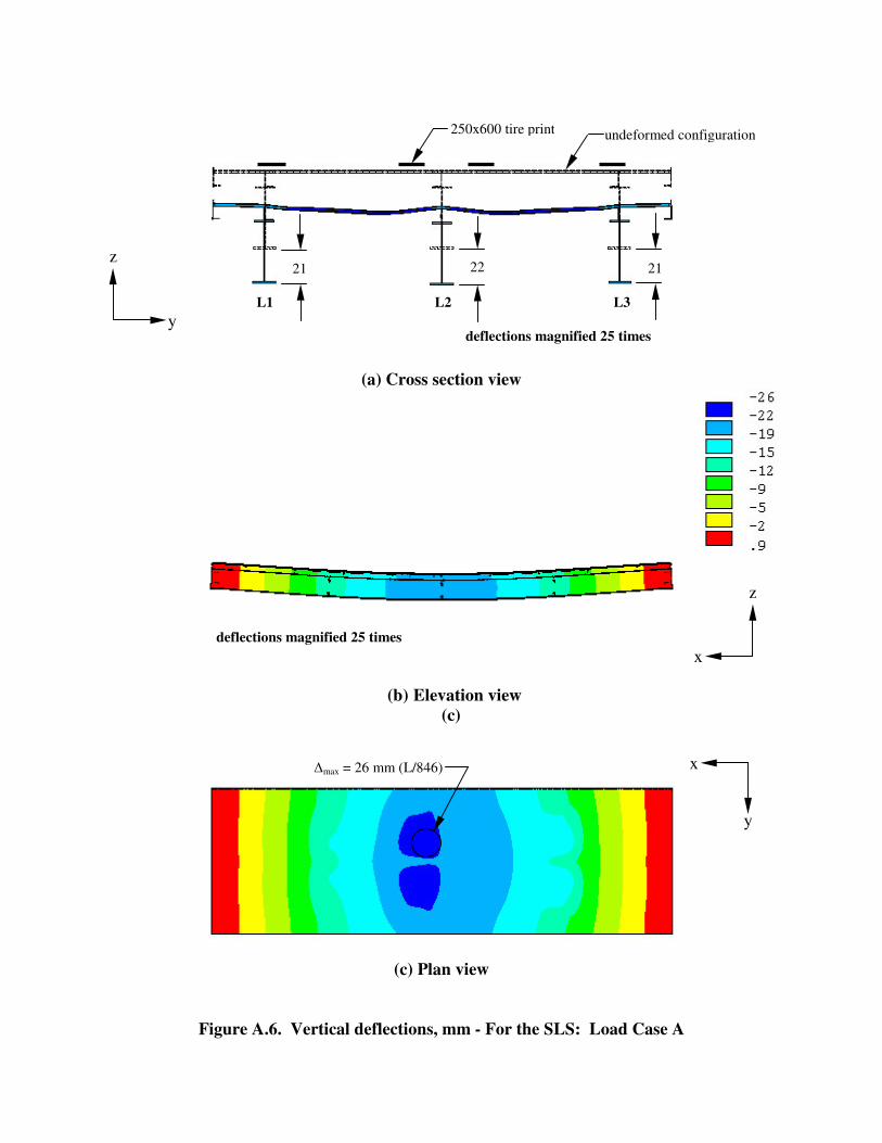
The vertical deflections of the bridge structure are plotted in Figure A.6 and include cross section, elevation and plan views. The cross section view illustrates the undeformed configuration and the deflected shape, where deflections are magnified by 25 times. The deflection of girders L1, L2 and L3 are 21 mm, 22 mm and 21 mm, respectively. The global deflection for the bridge structure is 26 mm and well within the serviceability criteria. Table 3.1 also gives the local deflection of the SPS bridge deck plate relative to the transverse angle webs. For all load cases, the local deflection also satisfies the serviceability criteria. A critical element of the SPS bridge deck plates is the V-groove welds joining adjacent panels when acted upon by negative bending moments that occur under the most severe loading event for the ultimate limit states producing maximum tensile stresses in the weld. The bending moment associated with the application of factored loads that occur after the weld is produced, include truck live loads and dead loads associated with the asphalt wearing surface and the guardrails. For load case B with trucks positioned to straddle the transverse angle webs, the normal stresses in the longitudinal direction averaged through the thickness of each of the SPS top and bottom plate were determined. The results are then applied to a local model, illustrated in Figure 3.2, as in-plane tensile stresses, in-plane compressive stresses and shear stresses acting on the SPS top plate and bottom plate respectively in combination with M20 ASTM A325M bolts pretensioned to 70% of the specified minimum tensile strength, Fu, of the bolt as specified in CSA S6-00. For this bolt, the specified minimum tensile strength is 830 MPa. Normal stresses at the top of the groove weld, illustrated in Figure 3.3, resulted from the applied dead and live loads. The factored tensile resistance of the weld, φwFu, is 322 MPa (0.67x480) for an E480XX electrode classification. The weld is more than sufficient to resist the 21 MPa total factored
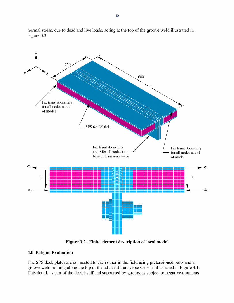
12
normal stress, due to dead and live loads, acting at the top of the groove weld illustrated in Figure 3.3.
Figure 3.2. Finite element description of local model 4.0 Fatigue Evaluation
The SPS deck plates are connected to each other in the field using pretensioned bolts and a groove weld running along the top of the adjacent transverse webs as illustrated in Figure 4.1. This detail, as part of the deck itself and supported by girders, is subject to negative moments
y
z
x
Fix translations in y for all nodes at end of model
Fix translations in y for all nodes at end of model
Fix translations in x and z for all nodes at base of transverse webs
SPS 6.4-35-6.4
�t
�c
t
�c
�t
t
600
250

13
tending to open the joint and putting the V-groove weld into tension. The Canadian Highway Bridge Design Code Bridge CSA S6-00 requires deck details to be analysed for the passage of a tandem set of 125 kN axles multiplied by a calibration factor of 0.62 to represent the fatigue truck with an incremental dynamic load allowance of 0.30 applied to this fatigue loading. The fatigue resistance of this connection and the groove weld in particular is investigated in this section.
Figure 3.3. Normal stress in longitudinal direction (x) at top of groove weld, MPa
Figure 4.1. Groove weld and pretensioned bolt connection detail
Groove weld subject to fatigue
x
z
�x = 21 MPa

14
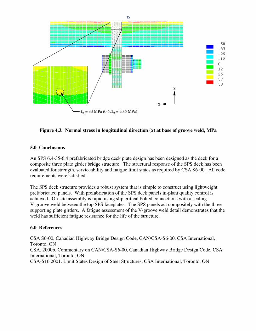
For an unlimited number of cycles, the stress range, fsr, calculated above, is not to exceed one half of the constant amplitude fatigue threshold stress range, Fsrt for the detail category most closely resembling the V-groove weld. This detail is considered to be a detail E category for which the corresponding allowable stress range for an unlimited number of cycles would be Fsrt /2 or 16 MPa. To determine the fatigue stress range of the groove weld connection, the finite element model illustrated in Figure 3.1 was analyzed with the tandem axles straddling the transverse 250x125x9.5 cold formed angle cross stringers of adjacent 1650 mm and 2400 mm wide SPS deck plates. The results are then applied to a local model, illustrated in Figure 3.2, as in-plane tensile stresses, in-plane compressive stresses and shear stresses acting on the SPS top plate and bottom plate respectively in combination with M20 ASTM A325M bolts pretensioned to 70% of the specified minimum tensile strength, Fu, of the bolt as specified in CSA S6-00. When the in-plane tensile and compressive stresses, �t and �c, and shear stresses, t, are applied to the local model as illustrated in Figure 3.2 with the pretensioned bolts at 500 mm spacing, the normal stress in the x-direction at the base of the groove weld is 20.5 MPa, as shown in Figure 4.3. From Figure 4.2, the corresponding fatigue life is estimated to be 108 cycles and with an anticipated traffic load of 120 trucks per day (43 800 cycles per year) this essentially gives an unlimited fatigue life. The fatigue resistance of the transverse joints between the SPS deck panels when acting compositely with the supporting girders is therefore adequate for the local effects of the CSA S6-00 fatigue loading.
Figure 4.2. S-N curves from CSA, CSA-S16 2001
Fsrt = 31 MPa
fsr = 20.5 MPa
15
Figure 4.3. Normal stress in longitudinal direction (x) at base of groove weld, MPa 5.0 Conclusions
An SPS 6.4-35-6.4 prefabricated bridge deck plate design has been designed as the deck for a composite three plate girder bridge structure. The structural response of the SPS deck has been evaluated for strength, serviceability and fatigue limit states as required by CSA S6-00. All code requirements were satisfied. The SPS deck structure provides a robust system that is simple to construct using lightweight prefabricated panels. With prefabrication of the SPS deck panels in-plant quality control is achieved. On-site assembly is rapid using slip critical bolted connections with a sealing V-groove weld between the top SPS faceplates. The SPS panels act compositely with the three supporting plate girders. A fatigue assessment of the V-groove weld detail demonstrates that the weld has sufficient fatigue resistance for the life of the structure. 6.0 References
CSA S6-00, Canadian Highway Bridge Design Code, CAN/CSA-S6-00. CSA International, Toronto, ON CSA, 2000b. Commentary on CAN/CSA-S6-00, Canadian Highway Bridge Design Code, CSA International, Toronto, ON CSA-S16 2001. Limit States Design of Steel Structures, CSA International, Toronto, ON
z
x fsr = 33 MPa (0.62fsr = 20.5 MPa)

16
Appendix A

(a) Top face of SPS top plate
(b) Bottom face of SPS bottom plate
Figure A.1. Maximum Normal Stress, MPa - Longitudinal Direction for the ULS: Load Case A
�max = 41 MPa
�max = -198 MPa
x
y
�max = 158 MPa
�max = -130 MPa
x
y

(a) Top face of SPS top plate
(b) Bottom face of SPS bottom plate Figure A.2. Maximum Normal Stress, MPa - transverse direction for the ULS: Load Case A
x
y
�max = -132 MPa
�max = 244 MPa
x
y
�max = 315 MPa
�max = -324 MPa
Top face of bottom plate
Bottom face of bottom plate

(a) Top face of SPS top plate
(b) Top face of SPS bottom plate
Figure A.3. Maximum von Mises Stress, MPa - For the ULS: Load Case A
x
y
�max = 241 MPa
x
y
�max = 320 MaP

20
(a) Longitudinal direction
(b) Transverse direction
Figure A.4. Interface Shear Stress, MPA - For the ULS: Load Case A
x
y
x
y
�max = 1.1 MPa
�max = 1.7 MPa

21
(a) Bottom flange of girders
(b) Top flange of girders
Figure A.5. Normal Stress, MPa - For the ULS – Girders in Longitudinal Direction: Load Case A
x
y
x
y
�avg = 150 MPa
�avg = -18 MPa
L1
L2
L3
L1
L2
L3
(a) Cross section view
(b) Elevation view (c)
(c) Plan view
Figure A.6. Vertical deflections, mm - For the SLS: Load Case A
�max = 26 mm (L/846) x
y
x
z
y
z
deflections magnified 25 times
deflections magnified 25 times
L1 L2 L3
250x600 tire print undeformed configuration
21 22 21