A New Generation of Avionics Electrical Design Software by...
12
White Paper: A New Generation of Avionics Electrical Design Software by Visual Engineer An in-depth look at how product lifecycle management software can overcome long standing problems in the aircraft completion industry.
Transcript of A New Generation of Avionics Electrical Design Software by...

White Paper: A New Generation of Avionics Electrical Design Software by Visual Engineer An in-depth look at how product lifecycle management software can overcome long standing problems in the aircraft completion industry.

White Paper: A New Generation of Avionics Electrical Design Software by Visual Engineer Page 1 Copyright © Visual Engineer, Inc. http://www.visual-engineer.com
A New Generation of Avionics Electrical Design Software by Visual Engineer
Table of Contents
Introduction .................................................................................................................................................. 2
Trouble in the Aircraft Completion Business ................................................................................................ 2
The Legacy Environment ............................................................................................................................... 2
Avionics Design Process ............................................................................................................................ 3
Recognizing the need for Change ................................................................................................................. 4
Is Software Development Really the Best Solution? ................................................................................. 5
The Solution – Product Lifecycle Management Software ............................................................................. 6
Automated Design - A New Paradigm for Electrical Engineering ............................................................. 7
Automated Error Prevention and Checking .............................................................................................. 8
Change Management ................................................................................................................................ 9
Reporting and Data Mining ........................................................................................................................... 9
Purchasing ............................................................................................................................................... 10
Manufacturing ........................................................................................................................................ 10
Technical Publications ............................................................................................................................. 10
Conclusion ................................................................................................................................................... 10

White Paper: A New Generation of Avionics Electrical Design Software by Visual Engineer Page 2 Copyright © Visual Engineer, Inc. http://www.visual-engineer.com
Introduction In today’s highly competitive environment amidst difficult economic times companies are increasingly being squeezed to do more with less. To anyone working in an organization today, this is no surprise. We have all seen it in the news and experienced it first hand in the office. Less staff, less time, less money and fewer overall resources all work against organizations as a sort of perfect storm jeopardizing the health of critical projects. In the aircraft completion industry delayed aircraft availability due to inefficient processes, engineering errors, troubleshooting installations and the subsequent rework all take their toll and work to strain customer relationships. In fact, it has been estimated that as much as 25% of any single avionics project will go towards reworking aircraft installations due to engineering mistakes. What would a 25% decrease in cost do to your organizations bottom line this year? What if your organization could achieve an additional 25% decrease in project cost by eliminating redundant work being performed by your engineers, production and purchasing departments? To address these issues and others the Visual Engineer team has designed a product lifecycle management system from the ground up that enables the engineering and manufacturing teams to work more efficiently while facilitating the electrical design process that is unique to the aircraft completion industry. The Visual Engineer solution is a true collaborative client/server database driven environment which is optimized for working with a team of electrical engineers and technicians on a project. At the heart of the Visual Engineer solution is their proprietary Electrical Engineering Management System™ that enables not only the engineers to work more efficiently but results in a ripple effect of increased efficiency across all departments. Organizations that have adopted Visual Engineer immediately realize a 50% decrease in labor hours to complete a project while enjoying a 99% reduction in design and production errors in all phases of their projects.
Trouble in the Aircraft Completion Business Witnessing the inefficiencies in the existing process used by aircraft completion and modification centers, the team at Visual Engineer set out to develop a new more efficient way for these organizations to work. After 20 years of experiencing the problems first hand that plague the industry it was clear that not only was a new set of tools needed but the whole process needed to be drastically overhauled as well. With this in mind the team at Visual Engineer identified and focused on three particularly painful areas where the entire process could be improved. These three areas are 1) automation of manual processes, 2) elimination of redundant tasks and 3) reduction of costly design mistakes.
The Legacy Environment Aircraft electrical systems are extremely complex. A typical aircraft completion may contain
thousands of components, accessories, wires and terminations, each containing their own unique set of attributes such as equipment identifiers, wire numbers, part numbers, accessories, and other technical specifications. This information must be managed by all individuals throughout the organization involved in the aircraft design cycles.
White Paper: A New Generation of Avionics Electrical Design Software by Visual Engineer Page 3 Copyright © Visual Engineer, Inc. http://www.visual-engineer.com
Today these electrical systems are designed with “off-the-shelf” mechanical software programs
such as AutoCAD™ that were created for automotive and other commercial industries. They were never intended to be used in the aircraft completion industry and simply lack the features necessary for efficient aircraft electrical systems design. These drawings do not have built in intelligence and are basically sketches consisting of lines, arcs and text. These types of applications do not offer any means to manage the electrical systems design. The avionics industry has used these tools for some time simply because there were no other viable options. Another shortcoming of these mechanical software programs is that they are typically single seat applications targeted towards the individual user. While some of these programs have started to include limited workgroup tools they still lack a true client/server approach. This greatly hinders the applications ability to meet the current challenges in the aircraft completion industry.
Avionics Design Process The process used today for installing aircraft electrical systems is very labor intensive. It requires extensive research, coordination and communication between the engineering, manufacturing and procurement teams. Today each process is a manual effort, one that is continuously repeated throughout the life cycle and susceptible to human mistakes.
A typical aircraft completion contains over one hundred thousand components, accessories,
wires and terminations. Information for each of these items are manually researched, drafted onto a wiring diagram, and then re-keyed into Excel™ spreadsheets so that the data can be managed and used by the other departments. Managing this information is challenging, for even the most experienced organizations. The electrical engineers create aircraft wiring diagrams that are used by manufacturing to install the electrical systems into the aircraft. Historically the tool of choice for creating these wiring diagrams has been AutoCAD™, a generic mechanical drafting program. Because AutoCAD™ is intended for mechanical drafting it lacks automation and other features relative to electrical systems design. The engineer has to literally draw every component, wire and attribute onto the drawing. The process is repeated for every instance of that component and wire on every drawing.
Every component used on the wiring diagrams requires an extensive amount of research to
ensure its compatibility and technical specifications. This research is performed by the engineer and requires a significant amount of their time, often as many as several hours for a typical piece of equipment. Once this information is obtained the engineer will make their notes for that component and then proceed with their work. It is not uncommon to have multiple engineers simultaneously searching for the same information. This research is continuously repeated for every piece of equipment on every project. This legacy approach lacks any type of centralized tool built into AutoCAD™ or other generic CAD applications to handle this process of “gathering and sharing”. This leads to one of your most expensive resources, avionics engineers all performing the same task on the same piece of equipment multiple times. Once the electrical design is completed, it is distributed amongst all other teams in the manufacturing cycle; mechanical engineering, manufacturing, procurement, and technical publications. Each team manually extracts the information that is required for their particular job function and then re-enters it into spreadsheets where it can be managed. This process is repeated by every team for every drawing. Many of these processes are manual in nature and susceptible to human mistakes. Compounded by the fact that there are over one hundred thousand components and terminations, it is

White Paper: A New Generation of Avionics Electrical Design Software by Visual Engineer Page 4 Copyright © Visual Engineer, Inc. http://www.visual-engineer.com
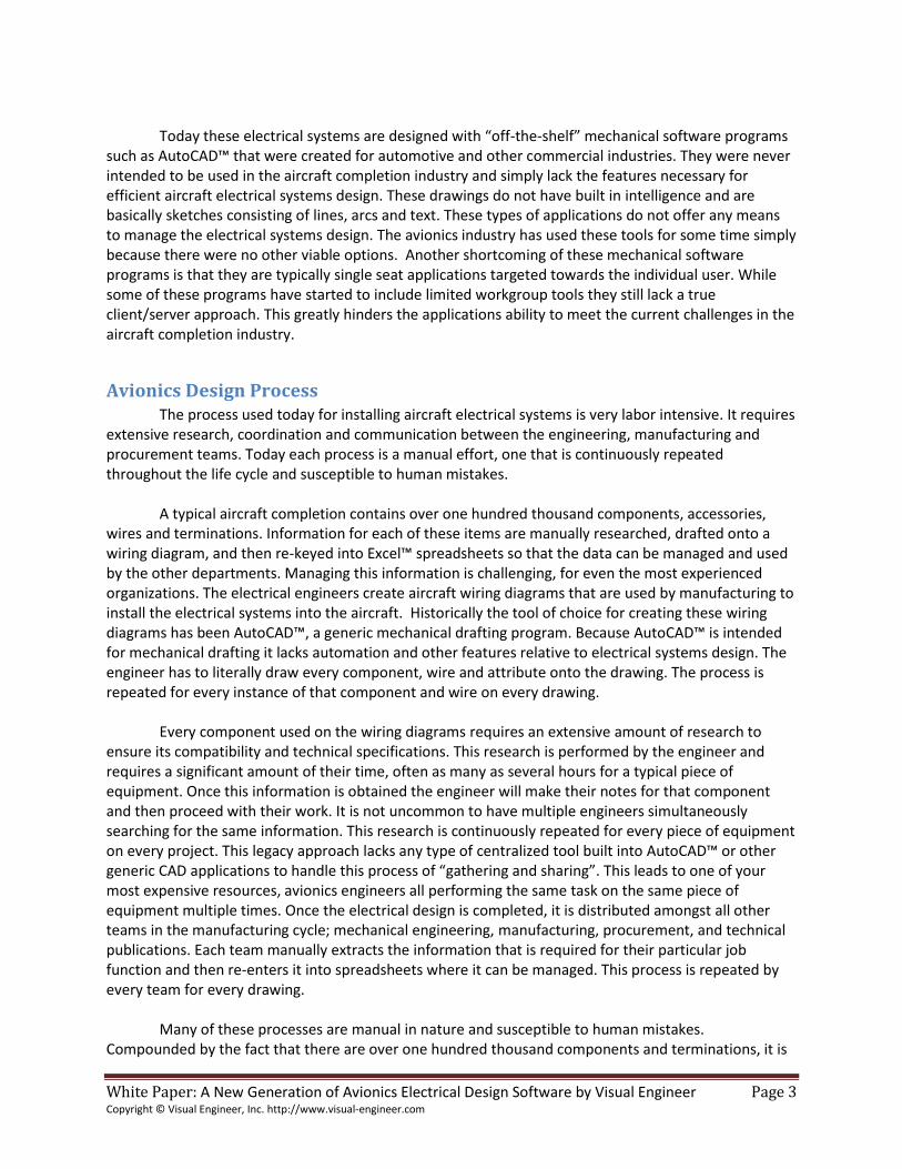
a certainty there will be many mistakes made throughout the course of a project. Mistakes on engineering drawings cause a domino effect throughout the organization. As you can see in figure 1 below a typical avionics project contains a myriad number of manual processes, each subject to human error.
PLAN
DESIGN
CHECK
DOCUMENT
REVISE
ELECTRICAL
DESIGN
MANUAL PROCESS
EXPLODE MAN HOURSREVISE
DRAWING
REVISEPARTS
LIST
REVISELOG BOOKS
REVISEAFFECTED
DRAWINGS
REVISEWIRELIST
REVISE
WIRE LIST
EQUIPLIST MATERIALS
LIST
HOOKUPLIST
DOCUMENT
CHECKPARTS
CHECKDESIGN
CHECKCONFLICTS
CHECK
LOGTERMINAL
BLOCKSLOG
EQUIP IDS
LOGWIRE IDS
LOGDISCONNECT
PINS
DRAFTWIRE
DIAGRAM
DESIGN
EQUIPSPECS
LOG EQUIPLOCATIONS
LOGDISCONNECTLOCATIONS
LOG TERMINAL BLOCK
LOCATIONS
PLAN
Figure 2. Manual processes in a typical Avionics design project One mistake in the design phase could easily equate to over one hundred hours of rework on the aircraft. If the mistake is not caught prior to release to production, then typically the entire assembly will need to be pulled from the aircraft. Up until now this legacy approach has been all the industry has known and is comparable to programming a website using mainframe punch cards. Sure it can be done but at what cost, and why would you choose that route when there are better options available.
Recognizing the need for Change Recognizing the shortcomings of the current legacy systems like AutoCAD™ and other mechanical CAD applications, aviation completion centers have begun to write custom software to address some of the shortcomings previously mentioned. The approach the industry has embarked on is

White Paper: A New Generation of Avionics Electrical Design Software by Visual Engineer Page 5 Copyright © Visual Engineer, Inc. http://www.visual-engineer.com
writing custom software that collects the attributes and specifications assigned to each individual component, terminal block, connector and wire. This is accomplished through a data entry form that is presented to the electrical engineer every time they add a component or wire to the drawing. For example the engineer may place a terminal connector or a new wire on the diagram. When a wire is placed on the diagram, a popup box comes up that is really a data entry form. The engineer then manually types the custom attributes and specification into the form and the information is automatically saved into a spreadsheet or in some cases a database behind the scenes. This process occurs for each component on each drawing by every engineer. Once the information is located in multiple spreadsheets or a database then custom software is used to create the necessary reports for purchasing, production and administrative tasks. This approach is somewhat better than the first generation legacy approach but is a significant source of errors and requires double entry work for all the engineers working on the project. Even assuming that the custom software built in-house works properly, the productivity of the engineer has not been improved. Each engineer is still entering the information twice, once on the drawing, and once in a form that links back to a spreadsheet or database. This leaves the quality and consistency of the information in question. What happens if the engineer enters the information one way on the form but another way on the wiring diagram? For example what if the diagram shows a wire terminated on pin 8 but it was entered in the form using pin 9? Even if the inconsistency is caught before it reaches production which source of information is correct? The research cost required to resolve these errors are enormous as is the labor cost to correct the issue, rerun all the reports, pull the assembly from the aircraft and have the production team make the change. Another question that this brings up is what happens if everything is entered correctly but a design change is needed to accommodate a larger terminal block or wire size. Currently changes on an electrical diagram using this method are not automatically changed on the spreadsheet or database, which means that the potential for the custom software to produce an accurate set of data is unlikely.
Is Software Development Really the Best Solution? Another problem with this approach is the entire custom software development process. It is not uncommon for labor cost to be the single largest expense item on a company’s income statement. Frequently custom software solutions that attempt to retro-fit AutoCAD™ or generic CAD applications are written by electrical engineers in an attempt to resolve the shortcomings of using a mechanical drafting package as an electrical engineering design tool. This approach is problematic as it takes the organizations most valuable resources, its employees (and probably some of their most expensive employees at that) and attempts to have them write software instead of aircraft completion design. Then the question of how to maintain the custom in-house software must be addressed. As vendors release patches or new versions of their generic CAD applications, organizations are often caught by surprise when their custom software stops working. These vendor induced bugs now force the organization to make a decision; roll back the patch released by the vendor for their CAD program, or spend more resources debugging and re-writing their in-house code to work with the new CAD release. This frequently occurs at the worst time, when projects are behind schedule and resources are already stretched thin. Couple this with the normal software bug cycles and the fact that the electrical engineers are now writing software instead of designing avionics systems, decreasing productivity. As the organization strays away from their core competency, they quickly realize that the savings they set out to achieve initially is lost in software development overruns and unexpected bug fixes.

White Paper: A New Generation of Avionics Electrical Design Software by Visual Engineer Page 6 Copyright © Visual Engineer, Inc. http://www.visual-engineer.com
The aircraft completion centers are to be commended for recognizing that there must be a better way. In the absence of any other viable alternatives it is easy to understand why they have turned to custom in-house software development to try and address these problems. What companies that embark on this path often end up with is a compromise that does not get them any closer to realizing the benefits originally intended. This is because the root of the problem originates in using a mechanical drawing application to perform electrical engineering design and the lack of a true data driven platform.
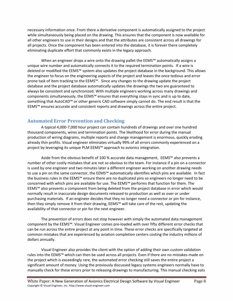
The Solution – Product Lifecycle Management Software The Visual Engineer team set out to design a new system or set of tools from the ground up that would enable the avionics engineers to work more efficient and facilitate the electrical design process to operate in a team environment. It was recognized early on that any solution that would support these design goals must be database driven in a client server environment. The database must be the foundation of the solution if real benefits were to be realized beyond what the avionics industry was already doing. Database technology has been around for nearly 30 years now and yet the aviation industry has not yet adopted database technology for automated drafting and design work. Now with Visual Engineer avionics engineers and in fact the entire organization can instantly reap the benefits of database technology. Looking for validation of this approach before embarking on a lengthy and expensive software development project, the team at Visual Engineer examined how other industries addressed similar challenges in their markets. One industry that immediately stood out was the automotive industry. Using product life-cycle management software (PLM) automotive manufacturers had already successfully solved the drafting, design, data management and production challenges that are similar to those in today’s aviation industry. Chrysler was one of the first companies to deploy PLM software in the automotive industry and realized significant competitive advantages in the market place [1]. Amongst the benefits realized were improved communications, decreased errors and conflicts, better data management and a reduction in design changes. In 1996, Chrysler’s development costs were 50% below the industry standard costs. This resulted in Chrysler having the lowest cost of production in the automotive industry at the time. Borrowing from the lessons learned in the automotive industry the team at Visual Engineer designed the first PLM software specifically targeted for the aviation modification and completion industry. What emerged from putting the database technology as the foundation of the product instead of the drawing package is absolutely revolutionary in the avionics industry. This was accomplished by enabling the drafting and design process to be data driven while creating the first true client/server PLM platform that completely manages the entire electrical engineering process. At the heart of the Visual Engineer PLM system is the electrical engineering management system™ (EEMS). The EEMS™ incorporates the business logic that manages everything from the first component that is placed onto a drawing to the point of supplying the installation team with the necessary document packets. EEMS™ is core to not only increasing the efficiency and effectiveness of the design work, but of the entire process (see figure 2 below). It really is a simple solution to a complex problem, sometimes simpler is truly better. (1))Hill S. How to be a trendsetter: Dassault and IBM PLM customers swap tales from the PLM front Retrieved 08/06/2011, Retrieved from http://legacy.coe.org

White Paper: A New Generation of Avionics Electrical Design Software by Visual Engineer Page 7 Copyright © Visual Engineer, Inc. http://www.visual-engineer.com
ENGINEERING
AUTOMATED
REPORTS
DATA MINING
TOOLS
PROCUREMENTCERTIFICATIONTECHNICAL
PUBLICATIONS
MANUFACTURING
MANAGEMENT
EEMS
Figure 2. Architectural diagram of the EEMS™. Visual Engineer provides a true collaborative client/server environment which is optimized for working with a team of electrical engineers on a project. All departments across the organization also immediately realize enormous gains in productivity and reduced errors as the result of the client server model and EEMS™. Architecturally Visual Engineer is completely different than AutoCAD™ and other CAD Solutions previously discussed. Visual Engineer starts with a server based application that uses the Microsoft SQL™ database engine. The EEMS™ is the centralized repository from which all drawings, reports and business logic originate.
Automated Design - A New Paradigm for Electrical Engineering Looking at the PLM solution that Visual Engineer has pioneered we can easily see the dramatic increase in efficiencies and decrease in errors when compared to the legacy platform in use today by the aviation industry. With Visual Engineer all components, equipment, wires, connectors and terminal blocks and their associated attributes are stored in a centralized database system called the master EEMS™ database. When an engineer opens up a Visual Engineer drawing they are able to immediately start leveraging the power of the EEMS™. Visual Engineer comes preloaded with over one thousand standard aircraft components ready to be used. To place a component on a diagram the engineer simply selects the appropriate component from the master database and drags and drops it onto the drawing pallet. From there the EEMS™ makes a derivative copy of the component behind the scenes, assigns the component a unique identifier and assigns it to the project database. The component on the drawing automatically has all the necessary attributes displayed so the engineer does not need to spend any time manually typing this information in on the drawing or making entries into a log book or a popup form. As new components are added to the project for the first time they are entered into the master database. The Engineer simply selects “new component” from the EEMS™ and then fills in all the
White Paper: A New Generation of Avionics Electrical Design Software by Visual Engineer Page 8 Copyright © Visual Engineer, Inc. http://www.visual-engineer.com
necessary information once. From there a derivative component is automatically assigned to the project while simultaneously being placed on the drawing. This ensures that the component is now available for all other engineers to use in their designs and that the attributes are consistent across all drawings for all projects. Once the component has been entered into the database, it is forever there completely eliminating duplicate effort that commonly exists in the legacy approach. When an engineer drops a wire onto the drawing pallet the EEMS™ automatically assigns a unique wire number and automatically connects it to the required termination points. If a wire is deleted or modified the EEMS™ system also updates the project database in the background. This allows the engineer to focus on the engineering aspects of the project and leaves the once tedious and error prone task of item tracking to the EEMS™. Since any changes to the drawing update the project database and the project database automatically updates the drawings the two are guaranteed to always be consistent and synchronized. With multiple engineers working across many drawings and components simultaneously, the EEMS™ ensures that everything stays in sync and is up to date, something that AutoCAD™ or other generic CAD software simply cannot do. The end result is that the EEMS™ ensures accurate and consistent reports and drawings across the entire project.
Automated Error Prevention and Checking A typical 4,000-7,000 hour project can contain hundreds of drawings and over one hundred thousand components, wires and termination points. The likelihood for error during the manual production of wiring diagrams, multiple reports and change management is enormous, quickly eroding already thin profits. Visual engineer eliminates virtually 99% of all errors commonly experienced on a project by leveraging its unique PLM EEMS™ approach to avionics integration. Aside from the obvious benefit of 100 % accurate data management, EEMS™ also prevents a number of other costly mistakes that are not so obvious to the team. For instance if a pin on a connector is used by one engineer and two minutes later a different engineer working on another drawing needs to use a pin on the same connector, the EEMS™ automatically identifies which pins are available. In fact the business rules in the EEMS™ ensure there are no duplicated pins so engineers no longer need to be concerned with which pins are available for use. The EEMS™ performs that function for them. The EEMS™ also prevents a component from being deleted from the project database in error which would normally result in inaccurate design documents released to production as well as over or under purchasing materials. If an engineer decides that they no longer need a connector or pin for instance, then they simply remove it from their drawing, EEMS™ will take care of the rest, updating the availability of that connector or pin for the next engineer. The prevention of errors does not stop however with simply the automated data management component by the EEMS™. Visual Engineer comes pre-loaded with over fifty different error checks that can be run across the entire project at any point in time. These error checks are specifically targeted at common mistakes that are experienced by aviation completion centers costing the industry millions of dollars annually. Visual Engineer also provides the client with the option of adding their own custom validation rules into the EEMS™ which can then be used across all projects. Even if there are no mistakes made on the project which is exceedingly rare, the automated error checking still saves the entire project a significant amount of money. Using the previously discussed legacy systems engineers normally have to manually check for these errors prior to releasing drawings to manufacturing. This manual checking eats

White Paper: A New Generation of Avionics Electrical Design Software by Visual Engineer Page 9 Copyright © Visual Engineer, Inc. http://www.visual-engineer.com
up hundreds of project hours and is itself prone to human error as not all errors are guaranteed to be caught. With Visual Engineer all errors that are programmed as checks are always caught 100% of the time. No matter how good an engineer is they will eventually have an off day and miss an error sooner or later. Visual Engineer never has an off day.
Change Management Automated change management has long been a necessity in the software industry with widely accepted tools like Visual Source Safe™ from Microsoft, BMC software and others. With millions of lines of code required for most applications the software industry recognized early on the need to manage change between the different versions of software in their releases. The aviation industry has a similar need to manage change between different versions of designs and all the ramifications associated with changes either in preliminary or released drawings. Once the drawing is released to production, changes on the drawing must be quickly identified and accounted for. Visual Engineer handles change management by keeping track of the complete history of changes for released drawings. This allows the engineers to quickly pinpoint what has changed between two revisions of a drawing without having to visually inspect each drawing. In fact, Visual Engineer can identify every single difference between multiple drawings from multiple projects in seconds. This is particularly useful for installation and certification teams as they can quickly and accurately identify changes to the design saving hours of research. When a project is completed all relevant drawings released or active including the various versions are added to a read only database. Additionally all components, wires, terminal blocks, connectors and equipment used on the project are also added to a read only database. This provides an audit trail of the entire project much like what the financial and accounting industry adopted many years ago. This way as new copies of the design work need to be reviewed or reprinted it is readily available. Additionally if future changes need to take place the finalized drawings and project database can simply be imported into a new project without having to start from scratch. This saves considerable time on new projects, resulting in lower cost which provides the organization with the ability to make a very competitive bid to retain that clients business.
Reporting and Data Mining As previously discussed the legacy approach taken by completion centers is not only burdensome and inefficient for the electrical engineers but for the entire organization. Departments such as purchasing, mechanical engineering, manufacturing, installation, accounting and even the sales department all depend on information contained within the electrical engineers design drawings. In fact, this bottleneck is the primary reason why organizations have resorted to custom in-house software development. Even with the use of custom software added on top of mechanical engineering software, accurate and real-time information still eludes the industry. Visual Engineer addresses this challenge by providing real-time reporting and data mining that provides targeted information to individuals in the organization at all levels and job functions eliminating the costly process of manually collecting and interpreting information from the design drawings.

White Paper: A New Generation of Avionics Electrical Design Software by Visual Engineer Page 10 Copyright © Visual Engineer, Inc. http://www.visual-engineer.com
Purchasing Purchasing for example can access the EEMS™ to determine which parts for a project need to be ordered and from what vendor. If an engineer adds a new connector to a project, purchasing will automatically and immediately see what was added, by whom and when. The purchasing department can view the reports for equipment needed by vendor or by equipment type.
Manufacturing After the electrical drawings are released to production, the installation teams extract information from each drawing to determine which equipment and wires need to be installed and terminated. Most organizations have individuals who are dedicated to this task. Since the EEMS™ automatically generates Equipment List, Wire Stamp List, Wire list, Hookup List and other installation reports; this step of the installation process is completely eliminated.
It is desirable for cabinet assemblies and other monuments to be pre-wired before installation of these assemblies in the aircraft. This requires the engineers to create cabinet assembly drawings that are basically sub-sets of the system drawings. Under the legacy approach this requires manually going through all drawings, extracting this information and re-drawing that part of the system for each cabinet or monument in the aircraft. For a typical project this can take upwards of 1,000 man hours provided no mistakes are made. This process is repeated when there are changes made to the systems drawings. Visual Engineer automatically generates cabinet assembly data packages that completely eliminate the need to spend costly labor generating this information.
Technical Publications Another area where thousands of hours are lost on a project is in producing what is called technical publications; documents necessary for the aircraft wiring diagram manual supplement. Technical publications typically contain equipment list, wire list and hookup list and other technical reports for the entire project. This is traditionally generated by manually going through every drawing and re-keying the information into Excel spreadsheets. Visual Engineer allows this to be generated on the fly permitting a weekly or even daily run for production. This saves thousands of man hours and prevents countless mistakes. Technical publications are critical for the organization because it is required for continued airworthiness as part of the FAA certification effort prior to delivery of the aircraft.
Conclusion Building on lessons learned from other industries the Visual Engineer team has accomplished the design goals they initially set out to achieve. But achieving design goals for a new software, tool or process no matter how revolutionary it may be is not enough. The real proof of such changes is in how it performs in the real world, in a busy aircraft completion center like yours where there are competing priorities, shortage of resources and real users sitting behind the screen. The team at Visual Engineer evaluated the success of their product by applying it to multiple aircraft completion projects to measure the effectiveness of their design goals and to determine if their PLM implementation hit the target. The feedback received was immediate and conclusive. Organizations that have adopted and implemented

White Paper: A New Generation of Avionics Electrical Design Software by Visual Engineer Page 11 Copyright © Visual Engineer, Inc. http://www.visual-engineer.com
Visual Engineer immediately experienced a significant increase in efficiency by eliminating manual processes, redundant tasks and common design mistakes. This increased the productivity of the electrical engineers allowing them to focus on design tasks instead of data management and research tasks. Early adopters of Visual Engineer without exception have enjoyed significant improvements in the speed and accuracy of the avionics design process. In fact, companies that use Visual Engineer frequently cite a 50% decrease in project completion time with a 99% reduction in errors which directly improves the profitability of the overall project. Adopters of Visual Engineer have also commented on the ripple effect of increased productivity throughout all areas of the organization involved with the aircraft completion projects. These high rates of return on investment are consistent with organizations in other industries that have successfully implement PLM solutions. The market research conducted by Visual Engineer combined with industry specific avionics experience and adoption of cutting edge technology has all contributed to the success of Visual Engineer in aircraft completion centers across the country. The Visual Engineer PLM solution has truly revamped the entire process to do more with less and faster. For more information and inquiries please visit www.visual-engineer.com/whitepaper