A New Approach Towards Surge Suppression and Insulation ... · A New Approach Towards Surge...
13
A New Approach Towards Surge Suppression and Insulation Monitoring for Medium Voltage Motors and Generators Abstract- Some 30 years ago, extensive investigations were launched into the root cause of premature winding failures of a large number of MV motors. This resulted in the discovery that pre-strike and re-strike switching transients were responsible. Field measurements proved the presence of these transients and provided the necessary information for developing models to understand the mechanisms involved. This understanding permitted the design and development of an RC device, attached to the motor terminals, which alters circuit parameters in such a way that pre-strike and re-strike transients are eliminated. The incorporation of a Zinc Oxide (ZnO) surge arrester deals with other spurious high magnitude steep fronted impulses. The combined ZnO and RC device is being marketed under the P Z trade name. A re-design which resulted not only in the capability for meeting the new test requirements, but also provided a platform for more efficient international manufacture and, in addition, a unique “window” for seeing into the winding and supply system of the protected equipment. This window is provided by the capacitance in the RC circuit and is particularly good because of its relatively high value. By adding a special purpose sensing circuit, combined with advanced analog and digital signal processing techniques, the becomes an extremely effective sensor for on-line monitoring of the condition of the winding insulation of the protected motor, generator or dry type transformer utilizing partial discharge analysis. It is more effective than coupling capacitors used for this purpose because of the wider frequency response afforded by the P . This permits seeing deeper into the windings and provides significantly improved coverage, which has always been a weakness of conventional coupling capacitor sensors. I. INTRODUCTION This paper is divided into two parts. Part 1 discusses the new surge protection technique and the technical benefits of such a device. Part 2 reviews the Partial Discharge (PD) sensor aspects that can be incorporated into the new surge protection technique for the monitoring of the insulation health of medium voltage equipment. II. A NEW SURGE PROTECTION TECHNIQUE A. Machine Impulse Voltage Withstand Capability The vulnerability of machine line-end coils to steep-fronted switching voltage transients was well researched and documented since the early 1970s [1, 2, 3, 4, and 5]. Due to the practical difficulty of testing and assessing inter- coil and inter-turn voltage withstand, various specifications exist for the maximum allowable steep-fronted voltages on motor terminals. The following examples are noted. IEC 60034-15 : 1995 o 66kV motors: 3,8pu at 0.2μs rise time o 11kV motors: 3,5pu at 0.2μs rise time. NEMA MG1-1998 : 2pu at 0,1 - 0,2μs rise time o 3,5pu when a higher surge capability is required by the Customer IEEE Standard 522: 1992: 3,5pu at 0.1μs rise time. A very important consideration is that an inter-turn insulation breakdown, during switching, may go undetected for some years, as the normal 50/60Hz voltage between turns is very low [3,4]. As a result, insulation degradation may occur over a prolonged period of time (e.g. another discharge may occur during subsequent switch-on or stalled tripping operations, thus leading to progressive insulation degradation). As recommended in IEEE Standard 522, it is advisable to fit a suitable surge suppression device in the motor circuit. B. Switching Transients Associated with Vacuum Switchgear Vacuum contactors and circuit breakers have become increasingly popular since the 1970s, but it was also recognized that they have one unique disadvantage over (for example) SF6 switchgear, namely potentially severe switching transients. Figure 1 shows typical sequential multiple prestriking during switch-on, while Figure 2 shows typical sequential multiple restriking, with voltage escalation during interruption of the motor starting current. Numerous papers have been published on this subject [1, 2, 3, 4, 5, 6, 7, and 8]. Claude Kane Alexander Golubev Dynamic Ratings, Inc 7308 Aspen Lane #153 Brooklyn Park, MN 55428 USA
Transcript of A New Approach Towards Surge Suppression and Insulation ... · A New Approach Towards Surge...

A New Approach Towards Surge Suppression and Insulation Monitoring for Medium Voltage Motors and Generators
Abstract- Some 30 years ago, extensive investigations were launched into the root cause of premature winding failures of a large number of MV motors. This resulted in the discovery that pre-strike and re-strike switching transients were responsible. Field measurements proved the presence of these transients and provided the necessary information for developing models to understand the mechanisms involved. This understanding permitted the design and development of an RC device, attached to the motor terminals, which alters circuit parameters in such a way that pre-strike and re-strike transients are eliminated. The incorporation of a Zinc Oxide (ZnO) surge arrester deals with other spurious high magnitude steep fronted impulses. The combined ZnO and RC device is being marketed under the PROTEC Z+ trade name. A re-design which resulted not only in the capability for meeting the new test requirements, but also provided a platform for more efficient international manufacture and, in addition, a unique “window” for seeing into the winding and supply system of the protected equipment. This window is provided by the capacitance in the RC circuit and is particularly good because of its relatively high value. By adding a special purpose sensing circuit, combined with advanced analog and digital signal processing techniques, thePROTEC Z+ becomes an extremely effective sensor for on-line monitoring of the condition of the winding insulation of the protected motor, generator or dry type transformer utilizing partial discharge analysis. It is more effective than coupling capacitors used for this purpose because of the wider frequency response afforded by the PROTEC Z+. This permits seeing deeper into the windings and provides significantly improved coverage, which has always been a weakness of conventional coupling capacitor sensors.
I. INTRODUCTION
This paper is divided into two parts. Part 1 discusses the new surge protection technique and the technical benefits of such a device. Part 2 reviews the Partial Discharge (PD) sensor aspects that can be incorporated into the new surge protection technique for the monitoring of the insulation health of medium voltage equipment.
II. A NEW SURGE PROTECTION TECHNIQUE A. Machine Impulse Voltage Withstand Capability The vulnerability of machine line-end coils to steep-fronted switching voltage transients was well researched and documented since the early 1970s [1, 2, 3, 4, and 5]. Due to the practical difficulty of testing and assessing inter-coil and inter-turn voltage withstand, various specifications exist for the maximum allowable steep-fronted voltages on motor terminals. The following examples are noted.
IEC 60034-15 : 1995 o 66kV motors: 3,8pu at 0.2µs rise time o 11kV motors: 3,5pu at 0.2µs rise time.
NEMA MG1-1998 : 2pu at 0,1 - 0,2µs rise time o 3,5pu when a higher surge capability is
required by the Customer IEEE Standard 522: 1992: 3,5pu at 0.1µs rise time.
A very important consideration is that an inter-turn insulation breakdown, during switching, may go undetected for some years, as the normal 50/60Hz voltage between turns is very low [3,4]. As a result, insulation degradation may occur over a prolonged period of time (e.g. another discharge may occur during subsequent switch-on or stalled tripping operations, thus leading to progressive insulation degradation). As recommended in IEEE Standard 522, it is advisable to fit a suitable surge suppression device in the motor circuit.
B. Switching Transients Associated with Vacuum Switchgear Vacuum contactors and circuit breakers have become increasingly popular since the 1970s, but it was also recognized that they have one unique disadvantage over (for example) SF6 switchgear, namely potentially severe switching transients. Figure 1 shows typical sequential multiple prestriking during switch-on, while Figure 2 shows typical sequential multiple restriking, with voltage escalation during interruption of the motor starting current. Numerous papers have been published on this subject [1, 2, 3, 4, 5, 6, 7, and 8].
Claude Kane Alexander Golubev Dynamic Ratings, Inc
7308 Aspen Lane #153 Brooklyn Park, MN 55428 USA

Fig 1. Sequential multiple prestriking in a vacuum contactor.
Fig. 2. Sequential multiple prestriking in a vacuum contactor with voltage
escalation.
Depending on the motor circuit configuration, its duty, the type of switchgear, etc, our practical experience has indicated the following potential worst case steep-fronted switching voltage magnitudes:
Switch-on : 3 - 4pu Interruption of the starting current: 4 - 5pu.
The worst case single prestrike voltage can be up to about 3pu in SF6 and air switchgear, and up to about 4pu during interruption of the starting current.
C. Optimized RC Surge Suppressors When an optimized RC surge suppressor is connected at the motor terminals (typically 0.1 – 0.3µF in series with a 30 - 50Ω non-inductive resistor per phase), it serves the following main purposes:
a) Voltage doubling, upon wavefront refraction, is eliminated.
b) The reflected current pulse is also eliminated, thus preventing a high frequency current zero in the switchgear. As shown in Figure 3, the switch current becomes aperiodic, thus eliminating multiple prestriking while the 50/60Hz motor currents builds up. Similarly, in the event of a restrike during tripping the motor 50/60Hz current is “re-connected” and final interruption then occurs at the next 50/60Hz current zero (Figure 4).
Fig 3. Elimination of multiple prestriking with an optimized RC surge
suppressor.
Fig 4. Elimination of multiple prestriking with an optimized RC surge
suppressor at point of interruption
D. Wavesloping Capacitors Traditionally, the North American approach (endorsed by the IEEE) has been to install wavesloping capacitors, with parallel surge arresters, at the motor terminals. This ensures that no steep-fronted transient switching voltages can be imposed on the motor terminals, as minimum rise times are in the order of 5µs or longer. The one disadvantage of this approach is that the undamped capacitors cause high frequency coupling between phases, resulting in three phase simultaneous interruption (also known as “virtual current chopping”) [3,4,6,7, and 8]. Figure 5 shows an example as recorded on a 6,6kV motor. The arrester “clipped” at about 2,8pu peak-to-ground, but the maximum peak-to-peak voltage was about 5pu.
Fig 5. 3-Phase simultaneous current interruption (“virtual current chopping”) in vacuum switchgear with a wavesloping capacitor and parallel surge arrestor
at the motor

Fig 6. Simplified single-line diagram of the PROTEC Z+ with optional Partial Discharge Module (PDM)
E. The PROTEC Z+ Surge Suppressor Functional Description Figure 6 shows a simplified single line diagram of the PROTECZ+. It is essentially a hybrid of a wavesloping capacitor and an optimized RC surge suppressor. Its basic functional description is as follows:
During normal switching conditions, it acts the same as an optimized RC surge suppressor, in that sequential multiple pre- and restriking is eliminated.
In the event of a steep-fronted voltage exceeding about 1,0 - 1,5pu, the small ZnO device activates, thus reducing the equivalent resistance in series with the capacitor. This then immediately effects wavesloping, as shown in the practical example in Figure 7. Furthermore, as the ZnO device “cuts out” when the voltage reaches its “target value”, no oscillatory transients occur (compare with Figure 5).
Fig 7. Effect of the PROTEC Z+ surge suppressor when a restrike occurs during interruption of the motor starting current
F. Additional Features of the PROTEC Z+ A decision was made to place the small ZnO arresters inside the 3-phase oil filled tank which houses the capacitor and resistor elements (Figure 6). The main considerations were as follows:
a) It must be possible to carry out type and routine tests on the individual R and C components in order to meet related international test requirements.
b) To allow an output connection for a Partial Discharge Monitor (PDM), as described in Part 2 of this paper.
c) Surge capacitors are known to have a fairly high failure rate, mainly due to harmonics in the power systems. The PROTEC Z+ has a pressure sensor that can be wired to the motor starter to prevent starting and/or tripping a machine when it is possible for the failure of the surge protection device. See addendum 2
III. PARTIAL DISCHARGE SENSING
Partial Discharge (PD) measurements and analysis is a well known and accepted method in assessing the condition of medium voltage insulation systems. Traditionally, coupling capacitors are installed in the line terminal box of a motor or generator or installed in the cable compartments of switchgear. Some vendors also use the resistive thermal devices (RTDs) found in rotating equipment as a complimentary PD sensor to the coupling capacitors and this also has proven to be very effective [10, 11, 12, 13, 15 and 15]. One of the key issues of measuring partial discharges in equipment is signal attenuation. Signal attenuation can be significant in rotating equipment due to their inductive nature. Figure 8 shows a typical coverage curve versus measurement frequency for a large machine. If one was measuring for PD at 25 kHz, the whole winding can be “seen” from sensors installed at the line terminals. As one moves up in the higher frequency range of measurement, less coverage of the winding is attained.
0 5 10 15 20 25 30 35 40 45 50 55 60 65 70 75 80 85 90 95 100
0.025
0.5
1
20
40
100
350
M H
z
% Relative Coverage
Fig 8. Effect of signal attenuation as a function of measurement frequency band
At the best, about 10-15% of the winding is covered by the industry accepted 80 pF coupling capacitor installed at the line terminals. PD occurring deeper in the winding is not
PD MONITOR
R
C
400V BUSHING
SINGLE PHASE LAYOUT OF PROTEC Z +
ZnO
SAFETY SWITCH
Piet
Typewritten Text

detectable by an 80 pF capacitor. A generally rule of thumb is perhaps the first two, maybe three coils can be monitored with these types of sensors on motors and perhaps the first bar on a large turbine generator. Attenuation is even a greater problem for cables. It is not uncommon to see microsecond or longer pulses traveling for one mile in a cable. Low capacitance couplers are unacceptable for PD measurements in cables. Implementation of the PROTEC Z+ allows one to easily incorporate PD detection circuitry as an external component to the PROTEC Z+ and is known as PROTEC Z+ System. This allows the PROTEC Z+ to become an extremely effective sensor for the online monitoring. The PROTEC Z+ allows one to utilize its high capacitance (up to 250nF), thus shifting the low frequency cut off to a frequency band of the measuring circuit to tens of kiloHertz. This permits the detection of partial discharges occurring deeper in the windings since signal attenuation is much less at the lower frequencies. This will significantly improve coverage, which has always been a weakness of conventional coupling capacitor sensors. It is possible the majority or the perhaps the complete winding can be monitored by the PROTEC Z+ System. A. Comparisons Made Three circuits were modeled using the same short duration pulse. Considerations for the surge impedance of the machine (source), feeder cable (R2) and for the lead between the PD sensor and the equipment terminals (Wire) are made.
80 pF coupling capacitor circuit (Figure 9a), 1 nF (1,000 pF) coupling capacitor (Figure 9b) PROTEC Z+ System (Figure 9c)
+
SOURCE
WIRE: 500nSOURCE: 50
SEN
: 80p
R1
50
R2
30
Out1
Fig. 9a . 80 pF coupling capacitor circuit
+
SOURCE
WIRE: 500nSOURCE: 50
SEN
: 1n
R1
50
R2
30
Out1
Fig. 9b. 1 nF (1,000 pF) coupling capacitor circuit
+
SOURCE
WIRE: 500n ZORC 1n
ZOR
C: 3
00p
ZOR
C: 3
0
SOURCE: 50
R2
30
ZORC 250n
CO
AX 5
0
Out1
Fig. 9c. PROTEC Z+ System
B. Comparison of Input and Output Signals Input and output signal level comparisons were made for the three circuits modeled above are shown in Figure 10a, b and c for 80 pF capacitor, 1 nF capacitor and a PROTEC Z+ System respectively for a short duration pulse.
T
Out1 SOURCE
Time (s)0.00 50.00n 100.00n 150.00n 200.00n
Vol
tage
(V)
-2.00
0.00
2.00
4.00
6.00
8.00
1.02
Out1 SOURCE
a
Fig. 10a. Input and output signal comparison for the 80 pF circuits. Some ringing occurs due to circuit characteristics.
T
Time (s)0.00 50.00n 100.00n 150.00n 200.00n
Vol
tage
(V)
-2.00
0.00
2.00
4.00
6.00
8.00
1.68
Out1 SOURCE
a
Fig. 10b. Input and output signal comparisons for the 1 nF circuit T
Time (s)0.00 50.00n 100.00n 150.00n 200.00n
Vol
tage
(V)
-2.00
0.00
2.00
4.00
6.00
8.00
1.28
Out1 SOURCE
a
Fig. 10c . Input and output signal comparisons for the PROTEC Z+ System
PROTEC Z+ System

As can be seen in Figure 10, the output signal for the PROTEC Z+ System is higher than that of an 80 pF coupling capacitor, even for a 20 ns pulse duration. This is a reasonable approximation for pulses originated in close proximity to a sensor. However, it is lower than that of a 1 nF coupling capacitor. Final comparisons were made of the Fast Fourier Transforms (FFT) of the output signals are shown in Figure 11.
T
Frequency (Hz)0 25M 50M 75M 100M
Am
plitu
de [V
]
0.00
50.00m
100.00m
150.00m
200.00m
Fig. 11a. Output FFT of an 80 pF Capacitor T
Frequency (Hz)0 25M 50M 75M 100M
Am
plitu
de [V
]
0.00
50.00m
100.00m
150.00m
200.00m
Fig. 11b. Output FFT of an 1nF (1,000 pF) Capacitor T
Frequency (Hz)0 25M 50M 75M 100M
Am
plitu
de [V
]
0.00
50.00m
100.00m
150.00m
200.00m
Fig. 11c. Output FFT of an PROTEC Z+ with PD Sensor
As can be seen, the PROTEC Z+ with the PD sensor installed has a very wide band of frequency response and is similar to that of a 1 nF capacitor sensor. When comparing the signals of Figure 11a to either of the other signals, it can easily be seen that the 80 pF signals have very low response at the lower frequencies. As a matter of interest, the 80 pF also has
low sensitivity at the higher frequency ranges where some suppliers measure Partial Discharge. This is the effect of the series inductance of the connecting wire between the coupler and HV terminals. This effect is identical for all coactively coupled sensors and actually causes the frequency band of hundreds of MHz not very useful with this type of PD technology. Special efforts must be taken to keep the connection inductance as low as possible for high frequency PD measurements. This is commonly impractical in real coupler installation. This is equally disadvantageous of using 80 pF capacitors and trying to measure for lower frequencies due to low capacitance of a sensor. C. Comparison of Pulse Width Response Figures 12a and b show the frequency response curves of magnitude versus pulse width for five different sensor configurations.
PROTEC Z+ System – configuration 1 (PROTEC Z+ 1n). This system is best for rotating equipment.
80 pF capacitor 1nF capacitor PROTEC Z+ with Configuration 2 (PROTEC Z+ 10n).
This system would be ideal for medium voltage cable systems.
PROTEC Z+ alone without PD System
Pulse Width Response
-0.5
1.5
3.5
5.5
7.5
9.5
11.5
0 200 400 600 800 1000 1200
Pulse Width - ns
No
rmal
ized
- A
mp
litu
de
- V
olt
sP
PROTEC Z+1n 80p 1000p PROTEC Z+ 10n
Fig. 12a. Pulse Width Response up to a pulse width of 1,000 ns. Best for cables
Pulse Width Response
-0.5
1.5
3.5
5.5
7.5
9.5
11.5
0 20 40 60 80 100 120
Pulse Width - ns
No
rmal
ized
- A
mp
litu
de
- V
olt
s
PROTEC Z+1n 80p 1000p PROTEC Z+10n
Fig. 12b. Pulse Width Response up to a pulse width of 100 ns. Best for rotating equipment.
There is a large move to monitor PD activity in cable systems in industrial systems. However, detection of long pulse widths can be troublesome. Use of the PROTEC Z+ 10n configuration nearly matches the total capability of the PROTEC Z+ by itself. This is depicted in Figure 12a. Use of an 80 pF capacitor is virtually useless.
PROTEC Z+
PROTEC Z+

Figure 12b zooms in the chart with a maximum of a 100 ns pulse. For pulses that have a short duration (These are pulses that are occurring close to the sensor), the 80 pF capacitor has a higher signal than that of all other sensors except a 1,000 pF capacitor. However, once the pulse width reaches 18 ns; all other sensors surpass the capability of the 80 pF capacitor. Pulses originating further away from the sensor will have longer pulse widths due to the well known signal attenuation issues. Referring back to Figure 1, the higher the frequency band of measurement, the less coverage there is of the monitored object.
IV. CONCLUSIONS
During normal switching conditions, the PROTEC Z+ acts the same as an optimized RC surge suppressor, in that sequential multiple pre- and restriking is eliminated. In the event of a steep-fronted voltage exceeding about 1,0 - 1,5pu, the small ZnO device activates, thus reducing the equivalent resistance in series with the capacitor. This provides enhanced protection of the connected equipment when compared to more common surge suppression techniques. The integration of the new PROTEC Z+ PD System sensing technology many advantages are achieved. One key advantage is the frequency response of the PROTEC Z+ System. This system provides significantly better response to longer pulses than the traditional 80 pF coupling capacitor, since signal attenuation is significantly less at the lower frequencies. This allows PD analyzers to see PD activity at greater distances from the sensing point when compared to an 80 pF capacitor. By combining the superior surge suppression features of the PROTEC Z+ and the partial discharge sensing technology, a very cost effective system is available for protection and monitoring of equipment. Applications can be for motors (including VFD Driven), generators, switchgear, transformers and cable systems. Interestingly this is one case where higher performance does not come at a price. By combining surge suppression and insulation monitoring in one device useful cost reductions over conventional solutions are possible. The PROTEC Z+ is therefore a unique new multi-functional device with enhanced capabilities and competitive advantages.
REFERENCES
[1] Nailen, R.E.: Transient surges and motor protection. Ind. and Com. Power System Tech. Conference, Seattle, 1979.
[2] Pretorius, R.E. and Eriksson, A.J.: A basic guide to RC surge suppression on motors and transformers. Trans. SAIEE, August 1980.
[3] Pretorius, R.E. and Eriksson, A.J.: Field studies of switching surge generation in high-voltage vacuum contactor controlled motors - results of extensive practical investigations. IEE 3rd International Conference on Sources and Effects of Power System Disturbances, London, May 1982.
[4] Pretorius, R.E.: Optimized surge suppression on high voltage vacuum contactor controlled motors. IEE 3rd International Conference on Sources and Effects of Power System Disturbances, London, May 1982.
[5] IEEE Working Group Progress Report: Impulse voltage strength of a.c. rotating machines. IEEE Trans. PAS, Vol. 199, No. 8, August 1981.
[6] Murano, M. et al: Three phase simultaneous interruption in interrupting inductive current using vacuum switches. IEEE PES Summer Meeting and EHV/UHV Conference, Vancouver, July 1973.
[7] Murano, M. et al: Voltage escalation in interrupting inductive current by vacuum switches. IEEE PES Summer Meeting and EHV/UHV Conference, Vancouver, July 1973.
[8] Development and application of vacuum circuit breaker model in electromagnetic transient simulation. Kendale Ras, B and Gopal Gajiar, Power India Conference, 2006 IEEE.
[9] IEEE P1434 “Guide to Measurement of Partial Discharges in Rotating Machinery, 1998.
[10] IEEE P1434 “Guide to Measurement of Partial Discharges in Rotating Machinery, 1998.
[11] Kane, C and A. Golubev, I. Blokhintsev "Advances in the Continuous Monitoring of Partial Discharges in Rotating Equipment", Waterpower, November 2003
[12] Kane, C and J. Pozonsky, S. Carney, I. Blokhintsev " Advantages of Continuous Monitoring of Partial Discharges in Rotating Equipment and Switchgear ", 2003 AISE Meeting, Pittsburgh, PA, September 2003
[13] Blokhintsev, I and M. Golovkov, A. Golubev, C. Kane “Field Experiences on the Measurement of Partial Discharges on Rotating Equipment”, IEEE PES’98, February 1-5, Tampa, FL
[14] Berler, Z and I. Blokhintsev, A. Golubev, G. Paoletti, A. Romashkov “RTD as a Valuable Tool in Partial Discharge Measurements on Rotating Machines ”Proceedings of 67th Annual International Conference of Doble Clients, March 27-31, 2000, Watertown, MA
[15] Berler, Z and A. Golubev, A. Romashkov, I. Blokhintsev “A New Method of Partial Discharge Measurements”, CEIDP-98 Conference, Atlanta, GA, October 25-28, 1998.
Addendum 1May 31, 2012
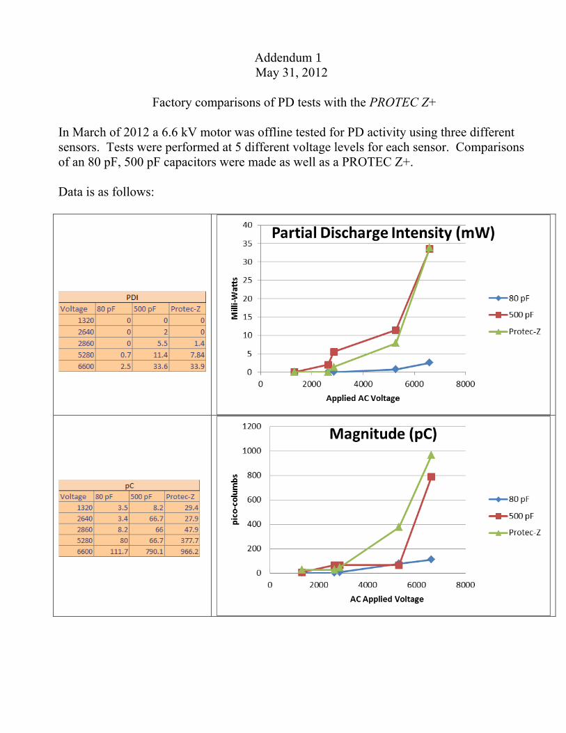
Factory comparisons of PD tests with the PROTEC Z+
In March of 2012 a 6.6 kV motor was offline tested for PD activity using three different sensors. Tests were performed at 5 different voltage levels for each sensor. Comparisons of an 80 pF, 500 pF capacitors were made as well as a PROTEC Z+. Data is as follows:
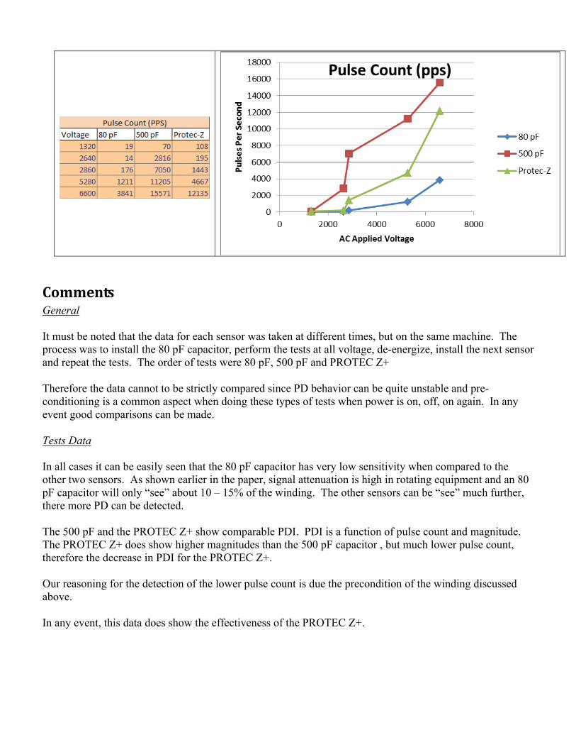
CommentsGeneral It must be noted that the data for each sensor was taken at different times, but on the same machine. The process was to install the 80 pF capacitor, perform the tests at all voltage, de-energize, install the next sensor and repeat the tests. The order of tests were 80 pF, 500 pF and PROTEC Z+ Therefore the data cannot to be strictly compared since PD behavior can be quite unstable and pre-conditioning is a common aspect when doing these types of tests when power is on, off, on again. In any event good comparisons can be made. Tests Data In all cases it can be easily seen that the 80 pF capacitor has very low sensitivity when compared to the other two sensors. As shown earlier in the paper, signal attenuation is high in rotating equipment and an 80 pF capacitor will only “see” about 10 – 15% of the winding. The other sensors can be “see” much further, there more PD can be detected. The 500 pF and the PROTEC Z+ show comparable PDI. PDI is a function of pulse count and magnitude. The PROTEC Z+ does show higher magnitudes than the 500 pF capacitor , but much lower pulse count, therefore the decrease in PDI for the PROTEC Z+. Our reasoning for the detection of the lower pulse count is due the precondition of the winding discussed above. In any event, this data does show the effectiveness of the PROTEC Z+.
Piet
Typewritten Text
Piet
Typewritten Text
Piet
Typewritten Text
Piet
Typewritten Text
Piet
Typewritten Text
Piet
Typewritten Text
Piet
Typewritten Text
Piet
Typewritten Text
Piet
Typewritten Text
Piet
Typewritten Text
Piet
Typewritten Text
Piet
Typewritten Text
Piet
Typewritten Text
Piet
Typewritten Text
Piet
Typewritten Text
Piet
Typewritten Text
Piet
Typewritten Text
Piet
Typewritten Text
Piet
Typewritten Text
PdMSA Conference – October 2011
Page 1 of 5
STATE OF THE ART TRANSIENT SWITCHING SURGE PROTECTION (TSSP) EQUIPMENT KNOWN AS THE PROTEC Z RANGE
Roger Billiet
NTSA, Johannesburg, South Africa
ABSTRACT
The need for Transient Switching Surge Protection (TSSP) equipment has never been more pressing. An overview of the emerging influences in the electrical networks since the inception of the initial TSSP device and their implemented solutions for protection of motors, generators and transformers against vacuum breaker switching spikes will be discussed. This paper will first sketch the situation in the 1980s and compares that situation with the contemporary networks Anno 2011. It shows that we never can take for granted that one can successfully navigate the world or the future on the basis of memory or the knowledge gained from the past. The initial solution had to be updated to the current realities. This is how the superb PROTEC Z range was conceived and implemented.
1. INTRODUCTION
The first Transient Switching Surge protection TSSP device was designed in South Africa by a truly unique top class consultant, Rapha Pretorius, in the early 1980s. It was initially conceived mainly for motors. The motor initial windings were failing because of the switching transients generated by vacuum circuit breakers. This device brought the solution. The vacuum breakers and contactors display a signature with the following characteristics:
• Rise time: 0.1-2 microseconds
• Frequency: 100-200 kHz
• Amplitude: 1-6 p u
• 1 p u = 0.8* V L-L
• V L-L is the three phase line to line system voltage
These high voltage and high frequency spikes hit the initial windings of the machine and cause extreme stress across the initial windings of the machine and this results in the so called ‘pinholes’. Over time these pinholes accumulate and cause inter-turn failures. The affected machine will then require a rewind with all its negative side effects. The biggest costs are most often the down
time of the production process. Other problems are found in breaker re-strike and pre-strike phenomena. South Africa was under sanctions when Rapha Pretorius engineered this initial Transient Switching Surge Protection device and the TSSP market was generally limited to this country. The internationalization of the market and the technological and environmental trends necessitated important updates, refinements and expansions of the design. This has been achieved in the PROTEC Z HV, Compact and LV units. Since 1980, many trends emerged with respect to:
• Power quality
• Machine characteristics
• Breaker issues
• Safety considerations
A discussion follows on these trends - one by one with an explanation of the improved characteristics that the PROTEC Z inherently possesses. 2. POWER QUALITY From 1980 - 1985, South Africa had a massive increase in new power stations. The economy was booming because of the mining sector expansions. The electricity tariff structure was relatively simple, the generation capacity was excellent and the networks were well maintained. Since then we are experiencing frequent load shedding, the inception of ‘green energy’, more non-linear loads, maintenance inadequacies and shortages of properly trained crew and engineers and increased lightning incidents because of global atmospheric influences. The effects of load shedding puts extra strain on the already heavily laden networks. It can cause brown outs and even black outs in severe cases. The loads are disconnected and reconnected and the TSSP needs to operate much more frequently to protect the machines. Their protective action is required increasingly more, even more so on the LV side. Green energy helps the networks but it cannot be depended upon at all times. The network needs to be underpinned by generators and UPS facilities in order to supply this shortfall. This translates again in increased switching operations. The need for PROTEC Z is evident.
2
0
Piet
Typewritten Text
Piet
Typewritten Text
Piet
Typewritten Text
Addendum 2
Piet
Typewritten Text
Piet
Typewritten Text
Piet
Typewritten Text

PdMSA Conference – October 2011
Page 2 of 5
Non-linear loads such as capacitors, chokes, VSD, UPS and oversaturated transformers cores create harmonics. These in turn can create serious problems with the following elements:
• Transformer overheating and winding failures • Failing of capacitors • Failing of VSD • Failing of UPS • Failing of Switched mode power supplies • Fuses age and interrupt prematurely • Filter failures • Existence of Super and Inter harmonics • Existence of standing waves • Switching problems • Earth fault incidences rise • Breaker failures • Protection failures • NER/NEC failures • Power electronics failures • Rectifier failures • Motor, generator and Dry Type Transformer
winding failure These effects also influence the older 1980 designed TSSP devices. The PROTEC Z design however has increased the original THD (V) <5% limit to 10% as standard and provision was made for situations were higher levels are required. The more intricate tariff requirements on a global scale and the increasing costs of copper and other conductor materials will increase the need for more power factor correction. This means more capacitors and more harmonic stressing of the insulation and other equipment cited above. The capacitors act as amplifiers in certain cases and can contribute to standing waves and resonance phenomena. The added risk is that the network can become over-capacitive with its negative influence on breaker behavior. This can lead to severe switching challenges Copper theft leads to badly earthed networks which lead in turn to over voltage situations and over-stressing of the networks and machinery. The possibility of alternative earthing can pose a real risk to the installations. The influence of maintenance inadequacies and shortages of properly trained crew and engineers further exacerbates this cycle of events as the need for corrective action is often not properly understood or inadequately implemented. 3. MACHINE CHARACTERISTICS As already alluded to, increased costs of copper and steel and relentless global competition from multinationals and the adoption of the World Trade Organization has led to smaller and higher optimized machines. This in turn has created new technological challenges such as the use of optimized core steel, narrower gaps in the machines and lower tolerance levels. The effects are possible capacitive coupling phenomena, flimsier insulation and possible amplification of transient switching and lightning spikes.
The harmonic influences and engineering deficiencies mentioned earlier are not improving the situation. The increased levels of harmonics and lightning incidence are likewise creating negative effects in these ‘optimized’ machines. Repairs and overhauls of these become more intricate as the tolerances are cut to the minimum. We can conclude that PROTEC Z is justified more than ever and an excellent case for the LV applications can be made. 4. BREAKER ISSUES Over the past thirty years, we have witnessed a transition from air and oil breakers to SF6 and even more prominent to vacuum breakers and vacuum contactors. Recently we witness an even bigger shift toward vacuum breaker and contactor solutions as the SF6 gas can cause cancer and appears not to be ‘green friendly’. The emergence of the ‘rotating arc’ is another improvement to protect the breaker and the contacts. However the claims made by some people that this also solves the problem of the transient switching spikes is over-optimistic. This judgment is based on the relative time scales and the fact that TSSP devices operate on voltage rather than current phenomena. 5. SAFETY ISSUES The initial design of the original TSSP did not rule out catastrophic failures. PROTEC Z has been designed with a higher THD (V) level (minimum 10%) and an ambient temperature of 55˚ Celsius. Units with higher THD (V) and ambient temperature limitations are designed and obtainable from NTSA. The original TSSP required checks on a regular basis on the eventuality of bulging tanks, bushings and oil leaks. These require maintenance and engineering skills which are often in short supply. These maintenance oversights can lead to failure to detect possible gas build up in the vessel and can lead to a rupture of it because of over pressure. The risk to human life and assets can be substantial. The PROTEC Z vessel is made from nonmagnetic stainless steel. This feature improves drastically the risk of rupturing of the vessel and potential loss of life, fire hazard and damage to the machines. However over and above this standard improvement, we have designed a safety switch feature which can be offered with each PROTEC Z HV and Compact unit. This feature measures on a continuous basis the internal vessel pressure. Once a preset level is exceeded the switch will operate and this can be used for alarming or tripping, thus clearing the emerging fault situation. The use of fuses is not recommended as a fuse can fail and if not detected, the particular affected winding on that phase of the machine can be damaged over time. 6. ULTIMATE TSSP DEVICE Improvements to the PROTEC Z include:
PdMSA Conference – October 2011
Page 3 of 5
• The stainless non-magnetic steel vessel ensures better containment and thus allowing for higher permissible ambient temperatures and/or harmonic loading and higher frequency and voltage variations.
• Special high harmonic voltage models are available.
• Stainless steel in the vessel design and has a much higher corrosion resistance than the initial 3CR12 1980 units. There will be no rusting even in coastal areas.
• The capacitor standards are to IEC 60871-1; VDE0560 part 410; ANSI/IEEE 18; NEMA CP-1
• Temperature range: -40/+55°C (-40/+131°F) as standard is achieved.
• Manufactured under IEC and CE standards in the European Union.
• ISO 9001 Bureau Veritas Certification • All of this results in a truly global competitive
product • Our ranges is from 400V to 25000V • The number of types and different models is
vastly reduced because the units are designed for multi-ranging applications.
• Competitive pricing • Ongoing research and improvement • Unique safety feature is available
The customer can now have complete peace of mind that the PROTEC Z is state of the art in TSSP equipment. The quality and safety aspects are optimized for all the issues discussed above under:
• Power quality
• Machine characteristics
• Safety considerations
Furthermore on an international scale, we fully comply with the global requirements in terms of standards and BIL ratings. The number of types is totally optimized in order to reduce any stocking costs. 7. DEVELOPMENTS Unique LV range with Class 1 lightning protection and superbly flexible and ultra-compact PROTEC Z LV units. These units will have an extremely small footprint and yet they will be able to protect motors, generators, transformer LV windings, UPS and VSD elements from the effects explained above. The transient switching transient signatures in low voltage follow those of the high voltage phenomena. These units will come in 2 types: 400V and 690V nominal units. These will be able to span voltages that are increased with 10% and decreased with 25% of the nominal value with frequency ranges of 50/60Hz.
The research resulted in the PROTEC Z +. This is a combined PROTEC Z HV unit inclusive of a safety switch and with an integrated PD monitor. This unit will both protect the machines in the conventional TSSP applications and offer a full PD analysis of the connected machine. Rotating machine analysis will be part of the monitor functions. The structure of this unit is a standard PROTEC Z with a T-in connection between the capacitor and the resistor-ZnO assembly. This T-in is then brought out to a LV bushing and coupled to the PD/rotating machine management unit. Types will be available for permanent monitoring and occasional monitoring dependent on the particular needs of the customer. Specialized training on how to do the installation and interpret the results is available. We have a complete team to offer these services as well. The technological challenges of this project combine several disciplines in the frequency spectrum: 50/60 Hz HV engineering, the tuning of the TSSP signature in the micro second range and the nano-second technology used in the PD monitor. A bonus will be that the unit will be able to observe phenomena deep into the machine windings 8. CONCLUSIONS Over the past 30 years important developments have taken place in the South African and global networks. The need for TSSP equipment has never been more pressing than now to protect the vulnerable initial machine windings from the spikes generated by Vacuum breakers. The PROTEC Z is uniquely designed to cover all the challenges as outlined; the innovative safety switch arrangement and its super-compact LV range offers high reliability and better protection of motors, generators and transformers. The PROTEC Z + is an exciting addition in the arsenal of machine management practitioners. The dual nature of this product is very cost effective. The PROTEC Z range is an overdue adaptation in order to make the TSSP technology inherently safe and suitably adapted and relevant to the current conditions in our current networks. 9. ADDENDUM: THE GENERAL LAYOUT OF THE FIRST TSSP DEVICE AND THE ADAPTATION TO ARRIVE TO THE PROTEC Z + MODEL

PdMSA Conference – October 2011
Page 4 of 5
It might be instructive to dwell upon the operation of the first TSSP. In such a unit as there are three interactive components that operate together as shown in figure1
• The Resistor
• The capacitor
• The Zinc Oxide element
The resistor and the capacitor create a tuned filter as shown in the figure. At the normal operating 50 or 60 Hz signals, they create a high resistive path. At the typical “signature” frequencies, the capacitor impedance is very significantly reduced and the spike is conducted to earth. The resistor also acts as a “make off” resistor, thus ensuring that restrikes are eliminated in the process. This greatly protects the breakers and the contactors from restrike phenomena. The ZnO element keeps the machine in line with the IEEE aging curves by operating the ZnO above a certain trigger point. The ZnO block then conducts and shunts the resistor out. The spike is then smoothed via the capacitor. One will notice that harmonic loading across the capacitor and the resistor will cause the current to increase across these elements. This increases the TSSP internal temperature and could give rise to degradation of the capacitor elements over time. This could start increased pressure in the vessel with catastrophic consequences over time.
Figure 1 Initial TSS model layout
The step to the PROTEC Z + with PD monitor is shown below in figure 2. Far from trivial are the connections the PD monitor. We have a very high frequency in the nano-second range to contend with, whereas the steady state of the filter is in the 50/60 Herz zone with the operational clipping zone in the very low microsecond range. Furthermore, the relative voltage levels are vastly different ranging from several kilo-Volt to very low volt signals. The unit is further equipped with a pressure switch to protect personnel and assets against any pressure build up in the vessel. This action can be coupled to the supervisory systems resulting in an alarm or connected to the breaker to shut the machine system down. The benefits of this layout is the combination of machine initial winding and breaker restrike protection with partial discharge monitoring and rotating machine management functions in one super compact assembly. This assembly calls for top class quality systems and high level engineering. These units are IEC approved. The vessel is nonmagnetic Stainless Steel to avoid any rust and to offer a high level of containment. The pressure switch will supervise all elements in the vessel. If there is any gas build up and it reaches the preset level, alarm or trip action can be initiated. Safety is of the most important concern as we are dealing with high voltages and the high potential likelihood that people will be close to the unit for measuring or analysis purposes.
Figure 2 PROTEC Z + Layout with PD monitor BIBLIOGRAPHY

PdMSA Conference – October 2011
Page 5 of 5
[1] Pretorius, R.E.: The generation of travelling waves in cable connected motor circuits and the effect thereupon of RC surge suppressor circuits. CSIR Special Report ELEK 90, December 1979 [2] Pretorius, R.E.: Optimised surge suppression on high voltage vacuum contactor controlled motors. IEEE 3rd International Conference on Sources and effects of Power System Disturbances, London, May 1982 [3] Pretorius, R.E. and Eriksson, A.J.: A basic guide to RC surge suppression on motors and transformers. Trans. SAIEE, August 1980. [4] Guide for the application of switching surge suppressors to medium voltage motors. Issued by the electrical power co-ordinating committee August 1992 [5] Yelland, C.P.: New developments in the protection of medium voltage AC motors from steep fronted surges. S.D. [6] Billiet, R.F.: The emerging influences since the inception of the initial transient switching surge protection device and their implemented solutions. December, 2010 NTSA [7] Billiet, R.F.: PROTEC Z LV the universal solution for transient switching protection for LV motors, generators, transformer LV windings, VSD, and UPS equipment. February, 2011, NTSA [8] Billiet, R.F.: Problems stemming from high THD (V) content in plants. March, 2011, NTSA [9] Billiet, R.F.: PROTEC Z-SSW with pressure switch, an application note. May, 2011, NTSA Principal Author: Roger Billiet holds degrees in
Electrical and Industrial Engineering and has obtained four Commerce degrees leading to Dr in Business Administration He worked at the Belgian Electricity board as an engineer before coming to South Africa in 1982. At present he is the General Manager of NTSA