CFD ANALYSIS OF A SURGE SUPPRESSION … Fluid Dynamics/Babak...CFD ANALYSIS OF A SURGE SUPPRESSION...
10
ANSYS konference 2010 Frymburk 6. - 8. října 2010 1 CFD ANALYSIS OF A SURGE SUPPRESSION DEVICE FOR HIGH PRESSURE RATIO CENTRIFUGAL Author: Ing. Martin BABÁK, Ph.D., První brněnská strojírna Velká Bíteš, a.s., e-mail: [email protected] Annotation: This paper describes the matter of a surge suppression device utilizing Internal Re- Circulation (hereinafter IRC) used for stable operating region enhancement of a high pressure ratio centrifugal compressor from PBS jet engine TJ 100A. Basic principle of the IRC is described here followed by description and results of CFD analysis of several different configurations of the device making use of FLUENT code. The results of performed experimental investigations are given for one configuration of IRC device in the end. Introduction Compact CC (Centrifugal Compressor) arrangement with high PR (Pressure Ratio) enable efficiency increase and thus fuel consumption decrease in the area of small aero engines. On the other hand the compact arrangement involves non-optimal geometrical compressor stage parameters due to restrictive dimension. As a consequence very high Mach number taking place at compressor inducer tip and such compressor stage is then expected to have poor stability. Application of IRC seems to be a way how to override this difficulty. Theory of IRC principles is still not well established and documented in published sources, especially in the area of high PR CF compressors. Furthermore IRC phenomenon is very complex due to transonic flow conditions, high speed rotation and geometry involved. That is why theoretical and experimental study was carried out in order to get better understanding of IRC surge suppression. Results of both are given and discussed in the paper IRC principle Internal Re-Circulation surge suppression technology utilizes pressure variation over outer (casing) wall in dependence on operating point location compared with surge line. Circumferentially averaged pressure distribution over compressor casing for three operating points of the same rotating speed is given on Fig.1 in dependence on z axis position (axis of revolution). Presented data was taken from CFD analysis of the CC. Inducer slot is placed downstream the inducer throat and IRC outlet is placed upstream compressor inducer on the casing wall as is shown on Fig 2. Re-Circulation increases mass flow through inducer throat in surge vicinity (-3% of mass flow - see Fig. 1) and by-passing inducer throat increases overall mass flow in choke region (+4% of mass flow).
Transcript of CFD ANALYSIS OF A SURGE SUPPRESSION … Fluid Dynamics/Babak...CFD ANALYSIS OF A SURGE SUPPRESSION...
ANSYS konference 2010
Frymburk 6. - 8. října 2010 1
CFD ANALYSIS OF A SURGE SUPPRESSION DEVICE FOR
HIGH PRESSURE RATIO CENTRIFUGAL
Author:
Ing. Martin BABÁK, Ph.D., První brněnská strojírna Velká Bíteš, a.s., e-mail: [email protected]
Annotation:
This paper describes the matter of a surge suppression device utilizing Internal Re-Circulation (hereinafter IRC) used for stable operating region enhancement of a high pressure ratio centrifugal compressor from PBS jet engine TJ 100A. Basic principle of the IRC is described here followed by description and results of CFD analysis of several different configurations of the device making use of FLUENT code. The results of performed experimental investigations are given for one configuration of IRC device in the end.
Introduction
Compact CC (Centrifugal Compressor) arrangement with high PR (Pressure Ratio) enable efficiency increase and thus fuel consumption decrease in the area of small aero engines. On the other hand the compact arrangement involves non-optimal geometrical compressor stage parameters due to restrictive dimension. As a consequence very high Mach number taking place at compressor inducer tip and such compressor stage is then expected to have poor stability. Application of IRC seems to be a way how to override this difficulty. Theory of IRC principles is still not well established and documented in published sources, especially in the area of high PR CF compressors. Furthermore IRC phenomenon is very complex due to transonic flow conditions, high speed rotation and geometry involved. That is why theoretical and experimental study was carried out in order to get better understanding of IRC surge suppression. Results of both are given and discussed in the paper
IRC principle
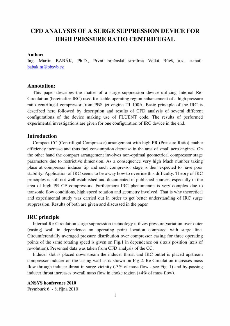
Internal Re-Circulation surge suppression technology utilizes pressure variation over outer (casing) wall in dependence on operating point location compared with surge line. Circumferentially averaged pressure distribution over compressor casing for three operating points of the same rotating speed is given on Fig.1 in dependence on z axis position (axis of revolution). Presented data was taken from CFD analysis of the CC.
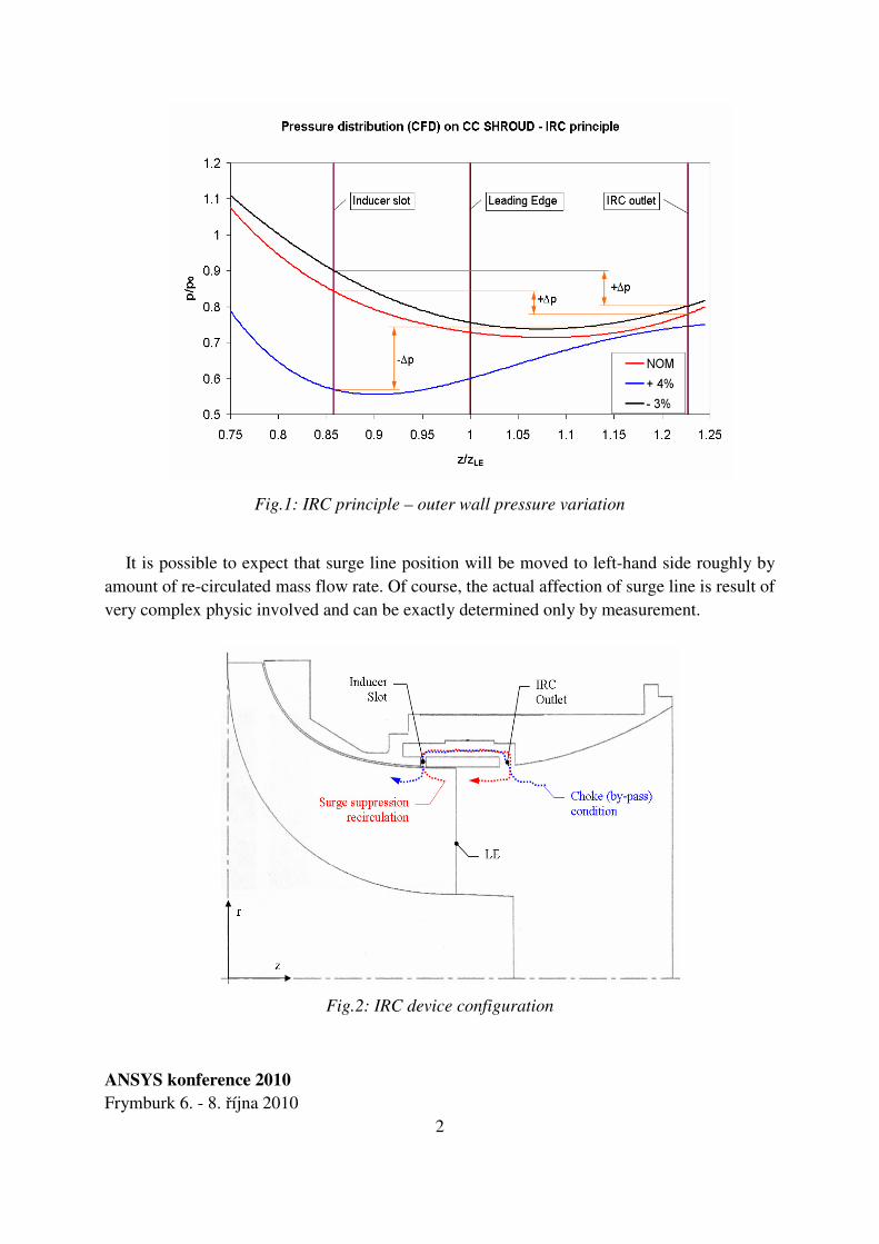
Inducer slot is placed downstream the inducer throat and IRC outlet is placed upstream compressor inducer on the casing wall as is shown on Fig 2. Re-Circulation increases mass flow through inducer throat in surge vicinity (-3% of mass flow - see Fig. 1) and by-passing inducer throat increases overall mass flow in choke region (+4% of mass flow).
ANSYS konference 2010
Frymburk 6. - 8. října 2010 2
Fig.1: IRC principle – outer wall pressure variation
It is possible to expect that surge line position will be moved to left-hand side roughly by amount of re-circulated mass flow rate. Of course, the actual affection of surge line is result of very complex physic involved and can be exactly determined only by measurement.
Fig.2: IRC device configuration
ANSYS konference 2010
Frymburk 6. - 8. října 2010 3
Employment of IRC obviously affects compressor performance and it has to be designed very carefully to avoid substantial performance deterioration in terms of pressure ratio and efficiency decrease.
Centrifugal compressor stage
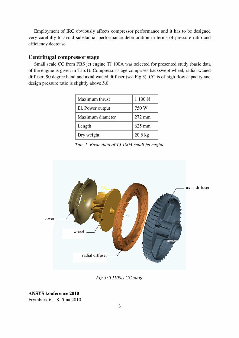
Small scale CC from PBS jet engine TJ 100A was selected for presented study (basic data of the engine is given in Tab.1). Compressor stage comprises backswept wheel, radial waned diffuser, 90 degree bend and axial waned diffuser (see Fig.3). CC is of high flow capacity and design pressure ratio is slightly above 5.0.
Maximum thrust 1 100 N
El. Power output 750 W
Maximum diameter 272 mm
Length 625 mm
Dry weight 20.6 kg
Tab. 1 Basic data of TJ 100A small jet engine
Fig.3: TJ100A CC stage
axial diffuser
radial diffuser
wheel
cover
ANSYS konference 2010
Frymburk 6. - 8. října 2010 4
Computational strategy
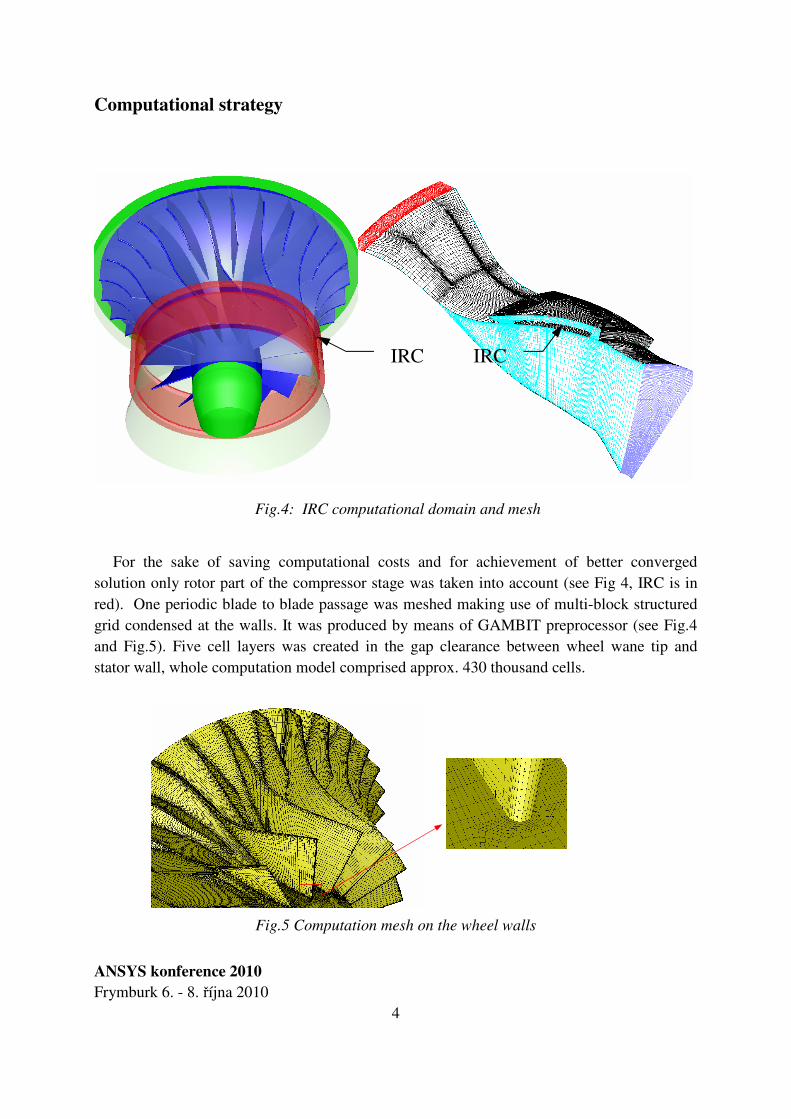
Fig.4: IRC computational domain and mesh
For the sake of saving computational costs and for achievement of better converged solution only rotor part of the compressor stage was taken into account (see Fig 4, IRC is in red). One periodic blade to blade passage was meshed making use of multi-block structured grid condensed at the walls. It was produced by means of GAMBIT preprocessor (see Fig.4 and Fig.5). Five cell layers was created in the gap clearance between wheel wane tip and stator wall, whole computation model comprised approx. 430 thousand cells.
Fig.5 Computation mesh on the wheel walls
IRC IRC
ANSYS konference 2010
Frymburk 6. - 8. října 2010 5
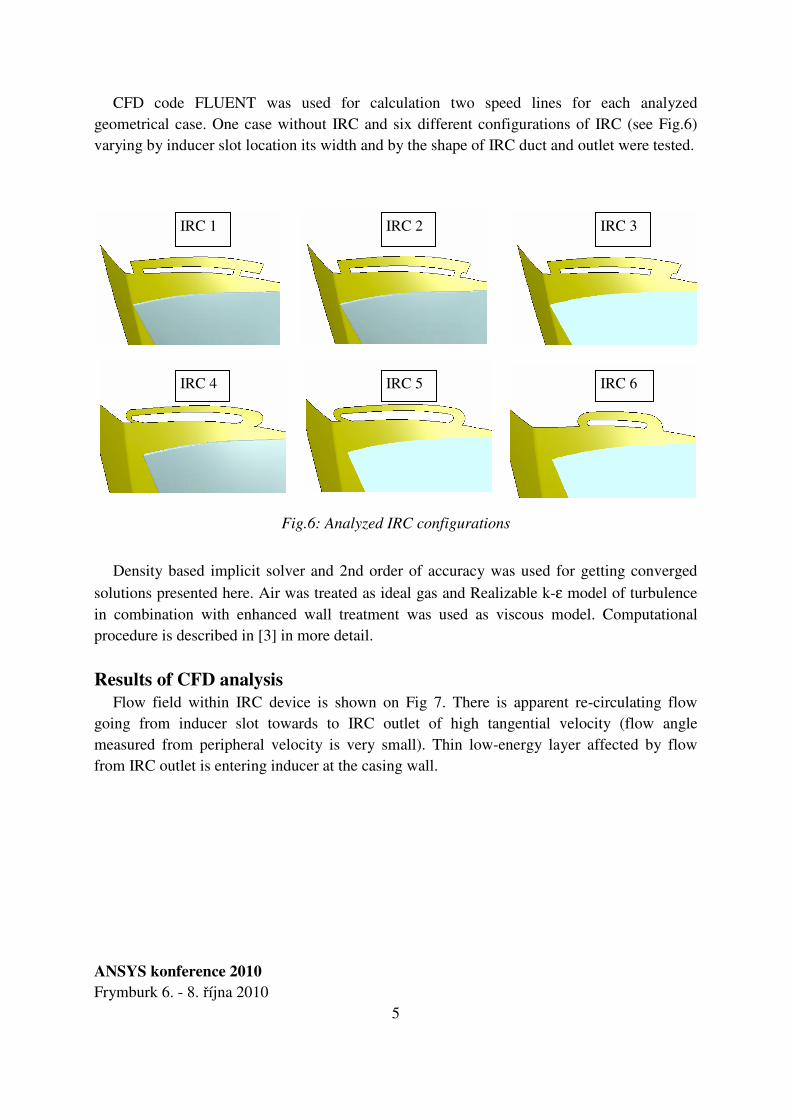
CFD code FLUENT was used for calculation two speed lines for each analyzed geometrical case. One case without IRC and six different configurations of IRC (see Fig.6) varying by inducer slot location its width and by the shape of IRC duct and outlet were tested.
Fig.6: Analyzed IRC configurations
Density based implicit solver and 2nd order of accuracy was used for getting converged
solutions presented here. Air was treated as ideal gas and Realizable k-ε model of turbulence in combination with enhanced wall treatment was used as viscous model. Computational procedure is described in [3] in more detail.
Results of CFD analysis
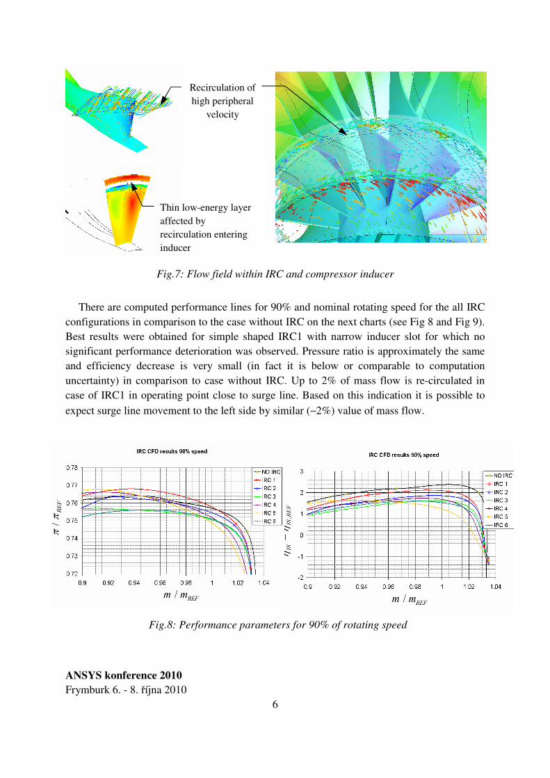
Flow field within IRC device is shown on Fig 7. There is apparent re-circulating flow going from inducer slot towards to IRC outlet of high tangential velocity (flow angle measured from peripheral velocity is very small). Thin low-energy layer affected by flow from IRC outlet is entering inducer at the casing wall.
IRC 1 IRC 2 IRC 3
IRC 4 IRC 5 IRC 6
ANSYS konference 2010
Frymburk 6. - 8. října 2010 6
Fig.7: Flow field within IRC and compressor inducer
There are computed performance lines for 90% and nominal rotating speed for the all IRC
configurations in comparison to the case without IRC on the next charts (see Fig 8 and Fig 9). Best results were obtained for simple shaped IRC1 with narrow inducer slot for which no significant performance deterioration was observed. Pressure ratio is approximately the same and efficiency decrease is very small (in fact it is below or comparable to computation uncertainty) in comparison to case without IRC. Up to 2% of mass flow is re-circulated in case of IRC1 in operating point close to surge line. Based on this indication it is possible to
expect surge line movement to the left side by similar (∼2%) value of mass flow.
Fig.8: Performance parameters for 90% of rotating speed
Recirculation of high peripheral
velocity
Thin low-energy layer affected by recirculation entering inducer
ANSYS konference 2010
Frymburk 6. - 8. října 2010 7
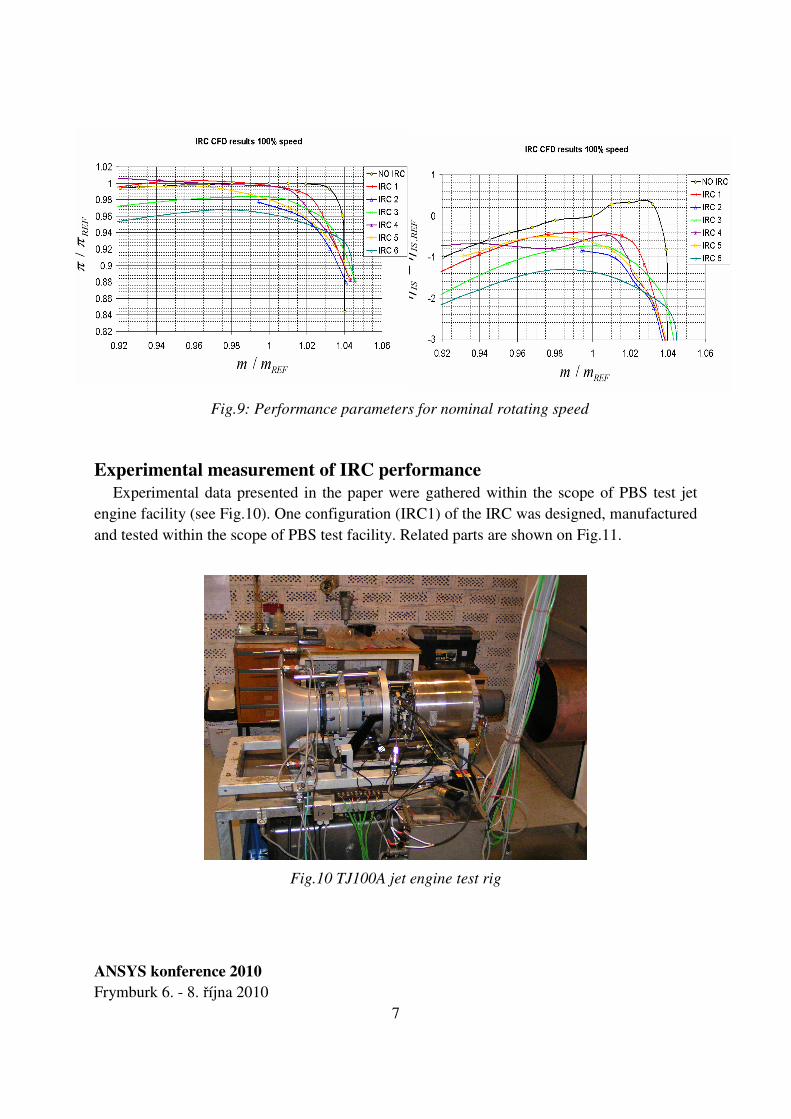
Fig.9: Performance parameters for nominal rotating speed
Experimental measurement of IRC performance
Experimental data presented in the paper were gathered within the scope of PBS test jet engine facility (see Fig.10). One configuration (IRC1) of the IRC was designed, manufactured and tested within the scope of PBS test facility. Related parts are shown on Fig.11.
Fig.10 TJ100A jet engine test rig
ANSYS konference 2010
Frymburk 6. - 8. října 2010 8
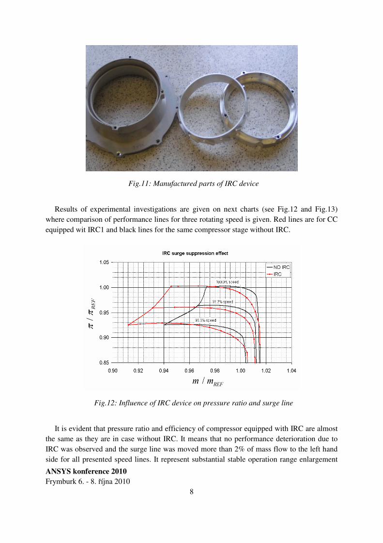
Fig.11: Manufactured parts of IRC device
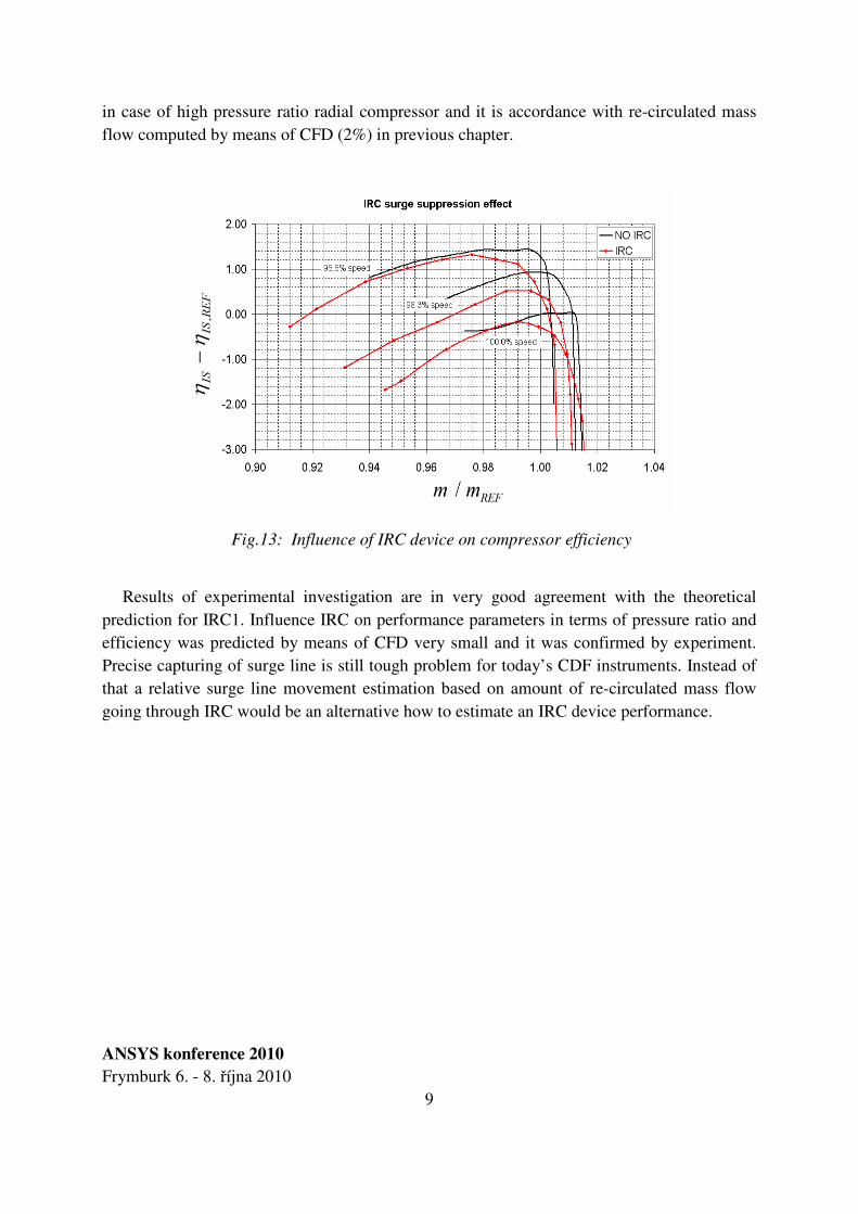
Results of experimental investigations are given on next charts (see Fig.12 and Fig.13) where comparison of performance lines for three rotating speed is given. Red lines are for CC equipped wit IRC1 and black lines for the same compressor stage without IRC.
Fig.12: Influence of IRC device on pressure ratio and surge line
It is evident that pressure ratio and efficiency of compressor equipped with IRC are almost the same as they are in case without IRC. It means that no performance deterioration due to IRC was observed and the surge line was moved more than 2% of mass flow to the left hand side for all presented speed lines. It represent substantial stable operation range enlargement
ANSYS konference 2010
Frymburk 6. - 8. října 2010 9
in case of high pressure ratio radial compressor and it is accordance with re-circulated mass flow computed by means of CFD (2%) in previous chapter.
Fig.13: Influence of IRC device on compressor efficiency
Results of experimental investigation are in very good agreement with the theoretical prediction for IRC1. Influence IRC on performance parameters in terms of pressure ratio and efficiency was predicted by means of CFD very small and it was confirmed by experiment. Precise capturing of surge line is still tough problem for today’s CDF instruments. Instead of that a relative surge line movement estimation based on amount of re-circulated mass flow going through IRC would be an alternative how to estimate an IRC device performance.
ANSYS konference 2010
Frymburk 6. - 8. října 2010 10
Conclusion
Theoretical and experimental results as well as performed comparison seem to be very promising. Significant enhancement of stable operation range was obtained in the case of IRC. Surge line was moved to left hand side by 2% of mass flow and no performance deterioration was observed. Furthermore CFD predicted results was in good agreement with experimental findings. Nevertheless ICR phenomenon is very complex and these first results are not enough to generalize rules and findings in case of different radial compressor. It is necessary to go on with theoretical and experimental studies to clarify all principles as well as recommendations and limits for usage IRC in high PR centrifugal compressor in general.
Acknowledgements
The work presented here was carried out in the frame of the NEWAC Project (FP6-030876) with co-funding from the European Commission within the 6th Framework Program.
REFERENCE
[1] Casey, M., 2003. Best practise advice for FCD in turbomachinery design, QNET-CFD Network Newslwtter Volume 2, No.3 – December 2003. [2] Gregory-Smith, D. G., 2001. Prediction of turbomachinery flow physic from CFD – revive of recent computations of appacet test cases, Task Quaterly, Gdansk 2001, ISBN 1428-6394. [3] Babák M., 2009. Effective computational procedure for high pressure ratio centrifugal compressor, Conference ANSYS 2009, Plzeň.