A Multi-Robot Search Using LEGO Mindstorms – An...
10
A Multi-Robot Search Using LEGO Mindstorms – An Embedded Software Design Project Paula Herber University of Potsdam August-Bebel-Str. 89, 14482 Potsdam Potsdam, Germany [email protected] Verena Klös Technische Universität Berlin Ernst-Reuter-Platz 7, 10587 Berlin Berlin, Germany [email protected] ABSTRACT Embedded software is concurrent, real-time dependent, typ- ically networked, must meet strict resource and high qual- ity requirements, and often runs on cheap hardware. Al- together, this makes the education of embedded software designers a difficult challenge. In this paper, we present an embedded software design project, where students have to develop a multi-robot search using Lego mindstorms. The main idea is to confront the students with all the spites that are typically present in embedded systems, while at the same time giving them an algorithmically non-trivial problem to solve. To this end, we let the students use a bio-inspired search algorithm (particle-swarm optimization) to detect survivors (led by cries for help) in an unknown dis- aster zone using a number of Lego Mindstorm robots. We have executed this project simultaneously at the University of Potsdam and TU Berlin and discuss results and evalua- tions. We think that this project is very well suited for the education of embedded software engineers. Categories and Subject Descriptors C.3 [Computer Systems Organization]: Special-purpose and application-based systems—Real-time and Embedded Sys- tems ; K.3.2 [Computing Milieux]: Computers and Edu- cation—Computer and Information Science Education General Terms Design Keywords Education, Embedded Systems, Multi-Robot Search ©Paula Herber and Verena Klös 2016. This is a minor revision of the work published in Proceedings of the WESE’15: Workshop on Em- bedded and Cyber-Physical Systems Education, Article No. 2, 2015, http://dx.doi.org/10.1145/2832920.2832922. Copyright is held by the authors. Publication rights licensed to ACM. 1. INTRODUCTION The amount of embedded software is steadily increasing. In [4], the authors state that the annual growth of the vol- ume of embedded software varies between 10 and 20 %. Embedded software engineers have to cope with this grow- ing complexity. At the same time, the systems are often networked and heavily interconnected. They typically con- sist of simple and often imperfect hardware, which imposes strict resource constraints, and, due to the interaction with the physical environment, the software must be designed to cope with real-time and concurrency. To meet all the re- quirements, embedded software designers need to know their hardware, and they need to cope with both functional and non-functional requirements. The steadily increasing complexity of embedded software together with the multi-demands in interdisciplinary appli- cations makes the education of embedded software engineers a difficult challenge. Embedded software engineers need to be able to apply software engineering methods, they need to know how to cope with the perils of cheap and unreli- able hardware, and they need to be able to work together with experts from various application fields (and/or become experts in the application field themselves). In this paper, we propose an embedded software design project, which we have designed to target all of the issues mentioned above. We are confident that this project can provide a valuable contribution to the education of embed- ded software engineers. The main idea is to confront the students with all the spites that are typically present in embedded systems (like imprecise sensors, limited resources and concurrency) and to give them an algorithmically non- trivial problem to solve. We let the students use a bio- inspired search algorithm (particle-swarm optimization) to explore an unknown disaster zone and to detect survivors (modeled as a non-linear sound source) using a number of Lego Mindstorm robots. Among the requirements is colli- sion avoidance, the ability to cope with an unstable blue- tooth connection, and the demand for an emergency mode where all robots have to return to their bases on the shortest possible path. We have executed this project simultaneously at the Uni- versity of Potsdam and TU Berlin and discuss results and evaluations. Our project is designed for students in the final year of their Bachelor or in the first year of their Master. A prerequisite for the successful execution of this project is that the students have already completed some background courses on software engineering and on embedded systems. They should have some knowledge about typical charac-
Transcript of A Multi-Robot Search Using LEGO Mindstorms – An...

A Multi-Robot Search Using LEGO Mindstorms– An Embedded Software Design Project
Paula HerberUniversity of Potsdam
August-Bebel-Str. 89, 14482 PotsdamPotsdam, Germany
Verena KlösTechnische Universität Berlin
Ernst-Reuter-Platz 7, 10587 BerlinBerlin, Germany
ABSTRACTEmbedded software is concurrent, real-time dependent, typ-ically networked, must meet strict resource and high qual-ity requirements, and often runs on cheap hardware. Al-together, this makes the education of embedded software designers a difficult challenge. In this paper, we present an embedded software design project, where students have to develop a multi-robot search using Lego mindstorms. The main idea is to confront the students with all the spites that are typically present in embedded systems, while at the same time giving them an algorithmically non-trivial problem to solve. To this end, we let the students use a bio-inspired search algorithm (particle-swarm optimization) to detect survivors (led by cries for help) in an unknown dis-aster zone using a number of Lego Mindstorm robots. We have executed this project simultaneously at the University of Potsdam and TU Berlin and discuss results and evalua-tions. We think that this project is very well suited for the education of embedded software engineers.
Categories and Subject DescriptorsC.3 [Computer Systems Organization]: Special-purpose and application-based systems—Real-time and Embedded Sys-tems; K.3.2 [Computing Milieux]: Computers and Edu-cation—Computer and Information Science Education
General TermsDesign
KeywordsEducation, Embedded Systems, Multi-Robot Search
©Paula Herber and Verena Klös 2016. This is a minor revision of the work published in Proceedings of the WESE’15: Workshop on Em-bedded and Cyber-Physical Systems Education, Article No. 2, 2015, http://dx.doi.org/10.1145/2832920.2832922.Copyright is held by the authors. Publication rights licensed to ACM.
1. INTRODUCTIONThe amount of embedded software is steadily increasing.
In [4], the authors state that the annual growth of the vol-ume of embedded software varies between 10 and 20 %.Embedded software engineers have to cope with this grow-ing complexity. At the same time, the systems are oftennetworked and heavily interconnected. They typically con-sist of simple and often imperfect hardware, which imposesstrict resource constraints, and, due to the interaction withthe physical environment, the software must be designedto cope with real-time and concurrency. To meet all the re-quirements, embedded software designers need to know theirhardware, and they need to cope with both functional andnon-functional requirements.
The steadily increasing complexity of embedded softwaretogether with the multi-demands in interdisciplinary appli-cations makes the education of embedded software engineersa difficult challenge. Embedded software engineers need tobe able to apply software engineering methods, they needto know how to cope with the perils of cheap and unreli-able hardware, and they need to be able to work togetherwith experts from various application fields (and/or becomeexperts in the application field themselves).
In this paper, we propose an embedded software designproject, which we have designed to target all of the issuesmentioned above. We are confident that this project canprovide a valuable contribution to the education of embed-ded software engineers. The main idea is to confront thestudents with all the spites that are typically present inembedded systems (like imprecise sensors, limited resourcesand concurrency) and to give them an algorithmically non-trivial problem to solve. We let the students use a bio-inspired search algorithm (particle-swarm optimization) toexplore an unknown disaster zone and to detect survivors(modeled as a non-linear sound source) using a number ofLego Mindstorm robots. Among the requirements is colli-sion avoidance, the ability to cope with an unstable blue-tooth connection, and the demand for an emergency modewhere all robots have to return to their bases on the shortestpossible path.
We have executed this project simultaneously at the Uni-versity of Potsdam and TU Berlin and discuss results andevaluations. Our project is designed for students in the finalyear of their Bachelor or in the first year of their Master.A prerequisite for the successful execution of this project isthat the students have already completed some backgroundcourses on software engineering and on embedded systems.They should have some knowledge about typical charac-
teristics of embedded systems, like concurrency, real-time,limited resources, and non-functional requirements. Theyshould also have learned and practiced (formal) specifica-tion and modeling techniques for embedded systems, e.g.timed automata or Statecharts, and temporal logics. Theyshould be familiar with programming techniques for concur-rent systems (tasks and processes, inter-process communica-tion, scheduling, shared resources), and, finally, they shouldhave some experience in C programming.
We start the semester with a few introductory lectures andexercises to bring the students to the same level of knowl-edge and to equip them with the necessary basic knowledgeon embedded systems, the employed software and projectmanagement. The project work itself starts two weeks afterthe beginning of the semester. Then, the weekly lectures arereplaced by oral milestone presentations about the progressin each project group every three weeks. The semester isclosed with a final presentation at the end of the semesterand oral exams, where the students explain and defend theircontributions to the project. The overall project is worth 9credit points (ETCS).
The remainder of this paper is structured as follows: first,we give some background information on Lego Mindstorms,the real-time operating system nxtOSEK, UPPAAL timedautomata, and particle swarm optimization. Then, we presentour embedded software design project, with a focus on theproject task and project organization and management. InSection 4, we discuss the technical challenges and results ofthe project. We briefly discuss our evaluation of the projectin Section 5, and conclude in Section 6.
2. PRELIMINARIESIn this section, we introduce the preliminaries that are
necessary to understand the remainder of this paper. Wefirst give a brief overview over the Lego Mindstorms hard-ware and the real-time operating system nxtOSEK for theLego Mindstorms programmable NXT. Then, we briefly in-troduce UPPAAL timed automata, a formal modeling lan-guage for real-time systems. Finally, we provide a short de-scription of the general ideas of particle swarm optimization(PSO).
2.1 Lego MindstormsThe Lego Mindstorms NXT 2.0 kit was released by Lego
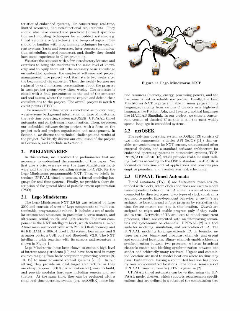
2009 and consists of a set of Lego components to build cus-tomizable, programmable robots. It includes a set of modu-lar sensors and actuators, in particular 3 servo motors, andultrasonic, sound, touch, and light sensors. The main com-ponent is the NXT intelligent brick, which features a 32-bitAtmel main microcontroller with 256 KB flash memory and64 KB RAM, a 100x64 pixel LCD screen, four sensor and 3actuator ports, a USB port and Bluetooth V2.0. The NXTintelligent brick together with its sensors and actuators isshown in Figure 1.
Lego Mindstorms have been shown to excite a high levelof interest among students [19] and have been used in manycourses ranging from basic computer engineering courses [9,10, 12] to more advanced control systems [7, 5]. In oursetting, they provide an ideal target architecture, as theyare cheap (approx. 300 $ per education kit), easy to build,and provide modular hardware including sensors and ac-tuators. At the same time, they can be equipped with asmall real-time operating system (e.g. nxtOSEK), have lim-
Figure 1: Lego Mindstorm NXT
ited resources (memory, energy, processing power), and thehardware is neither reliable nor precise. Finally, the LegoMindstorms NXT is programmable in many programminglanguages, ranging from various C dialects over high-levellanguages like Python, Ada, and Java to graphical languageslike MATLAB Simulink. In our project, we chose a concur-rent version of classical C as this is still the most widelyspread language in embedded systems.
2.2 nxtOSEKThe real-time operating system nxtOSEK [13] consists of
two main components: a device API (leJOS [11]) that en-ables convenient access for NXT sensors, actuators and otherexternal devices, and a standard software architecture forembedded operating systems in automotive systems, TOP-PERS/ATK OSEK [18], which provides real-time multitask-ing features according to the OSEK standard. nxtOSEK isfocused on real-time control applications and provides pre-emptive periodical and event-driven task scheduling.
2.3 UPPAAL Timed AutomataTimed automata (TA) [1] are finite-state machines ex-
tended with clocks, where clock conditions are used to modeltime-dependent behavior. A TA contains a set of locationsconnected by directed edges. Two types of clock constraintsare used to model time-dependent behavior: Invariants areassigned to locations and enforce progress by restricting thetime the automaton can stay in this location. Guards areassigned to edges and enable progress only if they evalu-ate to true. Networks of TA are used to model concurrentprocesses, which are executed with an interleaving seman-tics and synchronize on channels. UPPAAL [2] is a toolsuite for modeling, simulation, and verification of TA. TheUPPAAL modeling language extends TA by bounded in-teger variables, binary and broadcast channels, and urgentand committed locations. Binary channels enable a blockingsynchronization between two processes, whereas broadcastchannels enable non-blocking synchronization between onesender and arbitrarily many receivers. Urgent and commit-ted locations are used to model locations where no time maypass. Furthermore, leaving a committed location has prior-ity over non-committed locations. The formal semantics ofUPPAAL timed automata (UTA) is given in [2].
UPPAAL timed automata can be verified using the UP-PAAL model checker, which supports requirements specifi-cations that are defined in a subset of the computation tree

logic CTL. The UPPAAL model checker explores all pathesof a given timed automata model to check whether a givenformula is true. As all state-of-the-art model checking tools,it also provides a counter-example if a property is not satis-fied on all pathes. This counter-example can also be used todemonstrate the reachability of a certain path. In particular,UPPAAL also provides a shortest path option, which can beused to compute the shortest possible path that witnessesthe reachability of a certain property. In [17], the authorshave shown how UPPAAL and the shortest path option canbe used to compute the shortest pathes for a number of mo-bile robots on a given map with static obstacles.
2.4 Particle Swarm OptimizationIn [14, 15], Pugh and Martinoli presented a concept to
solve the multi-robot search problem by using particle swarmoptimization. Particle swarm optimization (PSO) as an op-timization technique was developed by Kennedy and Eber-hart [8]. The main idea is to model a set of potential solu-tions for a given problem as a swarm of particles searching ina virtual space for good solutions. The method was inspiredby the movement of flocking birds and their interactions withtheir neighbors.
The PSO algorithm works as follows [14]: Every particle inthe swarm begins with a random position xi and (possibly)randomized velocity vi in an n-dimensional search space,where xi,j represents the location of particle i in the j-thdimension of the search space. Each particle remembersat which position it achieved the best result so far x∗
i,j , andwhich particle achieved the best overall position in its neigh-borhood x∗
i′,j . Then, at each step, a PSO algorithm executesthe following equations:
vi,j = w · vi,j + wp · rand() · (x∗i,j − xi,j)
+wn · rand() · (x∗i′,j − xi,j)
xi,j = xi,j + vi,j
Where wp is the weight given to the previous best locationof the current particle and wn is the weight given to the pre-vious best location of the particle neighborhood, and rand()yields a uniformly-distributed random value in [0, 1]. ThePSO-inspired multi-robot search presented in [14, 15] usesa one-to-one matching between particles in the PSO swarmand robots in the multi-robot system.
3. EMBEDDED SOFTWAREDESIGN PROJECT
The aim of our embedded software design project is toteach the students to work together in a team on a complexembedded software design. Besides the embedded softwaredesign task itself, our goal is that they gain experience inproject management and organization. In particular, theyshould learn how to divide a comparatively large design taskinto smaller tasks, and how to communicate between multi-ple teams that are working on subsystems, which are laterintegrated into one system. The system integration is one ofthe main challenges in embedded system design. This hasseveral reasons:
• Subsystems are designed by experts of various domains.
The behavior of one subsystem is only partially under-stood by the designers of another subsystem.
• All subsystems are concurrent. Thus, the overall sys-tem behavior is hard to predict.
• Processing and memory resources are limited. Re-source access must be managed, and the overall re-source consumption must be controlled.
• Some processes are real-time dependent. Their correcttiming behavior must still be ensured if their executionis interleaved with other processes.
• All sensors, actuators, and communication devices mustbe assumed to be unreliable and inaccurate. As a con-sequence, subsystems can not always rely on results oranswers from other subsystems.
In the following subsections, we will first define the projecttask and briefly summarize the corresponding requirementsdefinition, which we have given to the students. Then, wewill briefly present our technical equipment and support. Af-ter that, we will discuss our project organization and projectmanagement. In the next section (Section 4), we will presentsome more details about the project execution itself, includ-ing exemplified design decisions, to give an impression ofthe technical challenges and detailed content of the projectwork.
3.1 Project TaskThe aim of the project is to implement a multi-robot
search in an unknown environment using a number of LegoMindstorms. The goal of the search is a non-linear soundsource. The motivating real-world application is the detec-tion and localization of survivors in a disaster zone, led bycries for help. In such scenarios, the use of autonomousmobile robots renders the use of human search personal un-necessary and thus may save lives and cost, in particularif the disaster zone is still considered unsafe, as is the casein the aftermath of earthquakes or flooding. A swarm ofsimple and cheap robots has the further advantage that itis tolerant against failures of a number of single robots, canexplore a given area quickly and scales well for larger areas.
Project Goal.The aim of the project is to design a swarm of at least
three mobile robots, which localize a sound source usingsound sensors. All movements must be planned and carriedout by local rules on each robot, e.g. by particle swarmoptimization as presented in [14, 15]. The swarm may com-municate via bluetooth, but has to cope with unstable andtemporarily unavailable bluetooth connections. Collisionsmust be avoided at all times and in all cases. At any time,a central control element may recall all robots to their basestations using an emergency mode. In this mode, the short-est path to return all robots to their base station is centrallycomputed and communicated to each robot, for example byusing the UPPAAL based approach presented in [17]. In theemergency mode, sound and ultrasonic sensors are switchedoff, so it is important that the algorithm to compute thepathes back to the base station for each robot is provablycollision free. This can be ensured by using the UPPAALmodel checker for the computation of the shortest path. Ifthe sound source is detected, the robots should indicate this

Figure 2: 2D search space
with a sound signal and broadcast the information to allother swarm elements and to the central control.
Simplifications.To enable our students to solve the project task within
one semester, we use the following simplifications of thisscenario:
• The robots move in a 2-dimensional search space, asshown in Figure 2.
• The search space is rectangular and its size is known.
• The search space is marked by a (physically detectable)grid, which enables orientation and positioning of therobots.
• The location of the sound source is as also marked onthe grid to simplify the physical identification of thegoal.
• Obstacles are cubes which have the same edge lengthas one field in the grid and are aligned to the grid.
• A PC may be used as a hub for the communicationbetween the robots, and to build and distribute a com-mon map from the information collected by all robots.
Additional Requirements.Besides the project goals defined above, we give the stu-
dents the following additional requirements:
• The hardware of the robots is identical for each groupand is developed by all groups together.
• All robots of one group run the same software.
• All robots start at a defined base station.
• The robots must never collide with each other or withobstacles.
• The resulting map should be shown on a PC.
• The performance of each solution is measured by thetime needed to find the sound source and by the qualityand robustness of the solution.
• Each solution must cope with unstable bluetooth con-nections.
Note that we give the complete project goal and all re-quirements to the students at the beginning of the semester.No requirements are changed during the semester, as thiswould go beyond the scope of one semester.
3.2 Technical Equipment and SupportFor the execution of this project, it is most advantageous
to have a project room that is solely dedicated for the useof the project during the whole semester. In our case, theproject rooms are equipped with a number of PCs runningUbuntu where we pre-installed the following software:
• The GNU ARM cross compiler from the Gnu CompilerCollection (GCC) [6], which supports the ARM7 CPUinside the NXT.
• John Hansen’s NeXTTool from the Programmable BrickUtilities repository [3], which can be used to commu-nicate with the NXTs via USB & Bluetooth (and thusalso enables program upload).
• The nxtOSEK real-time operating system, which canbe compiled together with user-defined C or C++ codeinto nxtOSEK applications for NXTs.
As building equipment for the mobile robots, we provideour students with five boxes of the 9797 LEGO© Mind-storms© Education Base Set together with five boxes ofthe 9695 LEGO© Mindstorms© Education Resource Set,plus five additional lightsensors.
As a project management platform, we have set up a Red-mine server together with a subversion (SVN) repository.The former is used by the students as a project planningtool, ticketing system, and online platform for informationexchange (discussion forums, document upload). The latteris used as a versioning and revision control system for shareddevelopment of the code base developed in the project.
3.3 Project OrganizationThe challenges of system integration in embedded soft-
ware design projects can only be met if the overall projectis properly managed. In students’ projects, the studentshave to self-manage their project work, typically in a non-hierarchical fashion.1 In our embedded software design project,we build groups of 8-9 students. Each group has to namepersons that are responsible for:
1. requirements, change, and risk management (defini-tion and evolution of requirements, identification andcommunication of changes and risks )
2. project planning (work breakdown structure, schedul-ing, milestones)
3. technical project management (interface definition, inter-process communication, communication between teamsworking on different subsystems, system integration)
4. quality assurance (coding standards, review strategies,verification and test plans)
1A hierarchical project management would not have thesame learning outcome for all the participants, and is diffi-cult to deploy within groups of students, for many reasons.
Motor & SensorControl
Communication Hub
Robot design PSOEmergencyMode
Multi-RobotSearch
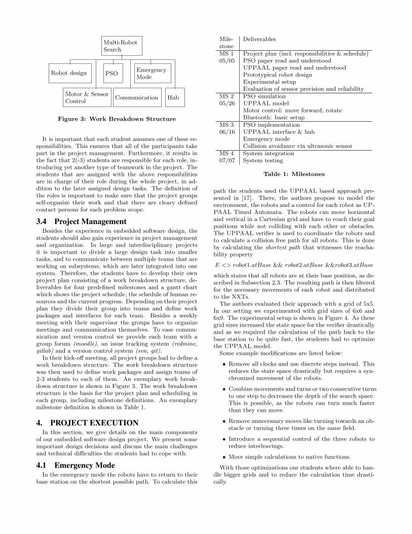
Figure 3: Work Breakdown Structure
It is important that each student assumes one of these re-sponsibilities. This ensures that all of the participants takepart in the project management. Furthermore, it results inthe fact that 2(-3) students are responsible for each role, in-troducing yet another type of teamwork in the project. Thestudents that are assigned with the above responsibilitiesare in charge of their role during the whole project, in ad-dition to the later assigned design tasks. The definition ofthe roles is important to make sure that the project groupsself-organize their work and that there are cleary definedcontact persons for each problem scope.
3.4 Project ManagementBesides the experience in embedded software design, the
students should also gain experience in project managementand organization. In large and interdisciplinary projectsit is important to divide a large design task into smallertasks, and to communicate between multiple teams that areworking on subsystems, which are later integrated into onesystem. Therefore, the students have to develop their ownproject plan consisting of a work breakdown structure, de-liverables for four predefined milestones and a gantt chartwhich shows the project schedule, the schedule of human re-sources and the current progress. Depending on their projectplan they divide their group into teams and define workpackages and interfaces for each team. Besides a weeklymeeting with their supervisor the groups have to organizemeetings and communication themselves. To ease commu-nication and version control we provide each team with agroup forum (moodle), an issue tracking system (redmine,gitlab) and a version control system (svn, git).
In their kick-off meeting, all project groups had to define awork breakdown structure. The work breakdown structurewas then used to define work packages and assign teams of2-3 students to each of them. An exemplary work break-down structure is shown in Figure 3. The work breakdownstructure is the basis for the project plan and scheduling ineach group, including milestone definitions. An exemplarymilestone definition is shown in Table 1.
4. PROJECT EXECUTIONIn this section, we give details on the main components
of our embedded software design project. We present someimportant design decisions and discuss the main challengesand technical difficulties the students had to cope with.
4.1 Emergency ModeIn the emergency mode the robots have to return to their
base station on the shortest possible path. To calculate this
Mile-stone
Deliverables
MS 1 Project plan (incl. responsibilities & schedule)05/05 PSO paper read and understood
UPPAAL paper read and understoodPrototypical robot designExperimental setupEvaluation of sensor precision and reliability
MS 2 PSO simulation05/26 UPPAAL model
Motor control: move forward, rotateBluetooth: basic setup
MS 3 PSO implementation06/16 UPPAAL interface & hub
Emergency modeCollision avoidance via ultrasonic sensor
MS 4 System integration07/07 System testing
Table 1: Milestones
path the students used the UPPAAL based approach pre-sented in [17]. There, the authors propose to model theenvironment, the robots and a control for each robot as UP-PAAL Timed Automata. The robots can move horizontaland vertical in a Cartesian grid and have to reach their goalpositions while not colliding with each other or obstacles.The UPPAAL verifier is used to coordinate the robots andto calculate a collision free path for all robots. This is doneby calculating the shortest path that witnesses the reacha-bility property
E <> robot1.atBase && robot2.atBase &&robot3.atBase
which states that all robots are at their base position, as de-scribed in Subsection 2.3. The resulting path is then filteredfor the necessary movements of each robot and distributedto the NXTs.
The authors evaluated their approach with a grid of 5x5.In our setting we experimented with grid sizes of 6x6 and6x9. The experimental setup is shown in Figure 4. As thesegrid sizes increased the state space for the verifier drasticallyand as we required the calculation of the path back to thebase station to be quite fast, the students had to optimizethe UPPAAL model.
Some example modifications are listed below:
• Remove all clocks and use discrete steps instead. Thisreduces the state space drastically but requires a syn-chronized movement of the robots.
• Combine movements and turns or two consecutive turnsto one step to decreases the depth of the search space.This is possible, as the robots can turn much fasterthan they can move.
• Remove unnecessary moves like turning towards an ob-stacle or turning three times on the same field.
• Introduce a sequential control of the three robots toreduce interleavings.
• Move simple calculations to native functions.
With those optimizations our students where able to han-dle bigger grids and to reduce the calculation time drasti-cally.

Figure 4: Experimental setup
4.2 Particle Swarm OptimizationAs basis for the local planning of movements the students
used the PSO algorithm from [14, 15] as explained in Sub-section 2.4. This algorithm can be adjusted and customizedfor the project setting to optimize the performance of theswarm. In our setting robots are only allowed to move up,down, left or right, but not diagonal on the grid. Thus, theactual movement has to be in the direction of the maximumof the x and y component of the velocity vector. An impor-tant adjustment concerns the target function. In our settingthe main task is to find the sound source. Therefore, themeasured sound value on a field is used to calculate the per-sonal and global best position for the robots. As the soundis varying and as the sound sensor is not precise this mea-surement can only be used as an estimate for the locationof the target. The possibility to physically detect the targetfield allows for a further adjustment of the target function.As long as the position of the sound source is unknown, ithas to be located on an unexplored field. Thus our studentsadjusted the velocity vector to prefer unexplored fields. Toachieve this, the calculated vector can be shifted towards anunexplored field nearby or clusters of unexplored fields canbe considered during the calculation by adding a personaland global best position concerning unexplored fields. Thefollowing formula shows such an adjusted calculation. Thepersonal best position b∗p consists of the personal best posi-tion related to the sound (s∗i,j) and the best position relatedto map information (m∗
i,j). Each part can be adjusted by aweight (wp,s, wn,s). The best position in the neighborhoodb∗n is calculated in the same manner.
vi,j = w · vi,j + wp · rand() · (b∗p − xi,j)
+wn · rand() · (b∗n − xi,j)
xi,j = xi,j + vi,j
b∗p = wp,s · s∗i,j + wp,m ·m∗i,j
b∗n = wn,s · s∗i′,j + wn,m ·m∗i′,j
To enable early evaluation and testing of the PSO algo-rithm without depending on the progress in the other com-ponents, a PSO simulation environment is needed. This canbe combined with the task to display the resulting map ona PC. Figure 5 shows a particular nice solution which waswritten in python by using the library pygame [16] whichis a set of python modules for video games. This simulatorallows for the initialization of the grid, a real time visual-ization of map informations (base, robot position, detectedobstacles, unknown fields, volume values, calculated PSO-vector, detected dead ends) as well as switching betweenthe modes (search and emergency). It also includes a visu-alization of the calculated UPPAAL paths (incl. calculationtime & number of steps of longest path).
4.3 Embedded Software DesignThe real embedded software design part of our project
consists of the components that finally run on the NXTsthemselves. These comprise the motor and sensor control,and a bluetooth communication layer. An important issuewas the system integration, namely to smoothly run all taskstogether on one NXT. Some groups had to reduce the num-ber of tasks in order to meet the strict memory constraintsimposed by the Lego Mindstorm architectures. All groupshad to carefully design the timing of their tasks by usingpreemptive periodic and event-driven tasks.
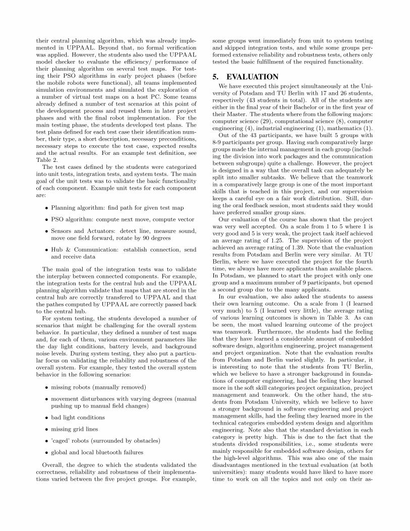
An exemplary task structure is shown in Figure 6. Allsensor tasks are periodic (indicated by a circular node), themotor control task and the main task are event-triggered(indicated by rectangular nodes). The tasks exchange events(E) and data (D). The motor stops (E0) in case of a detectedlight change (E1) or obstacle (E2). It is controlled by eventsfrom the MainTask ( E3: one of adjust, moveF, rotateLor rotateR) and corresponding motor control values (D0)and reports whether the move was successful (E4: one ofmoveDone, moveFailed). The MainTask also sets defaultvalues for the light sensor (D1) and exchanges audio andultrasonic sound signals (D2) with the SensorTask.
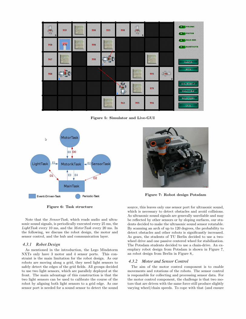
Figure 5: Simulator and Live-GUI
Figure 6: Task structure
Note that the SensorTask, which reads audio and ultra-sonic sound signals, is periodically executed every 25 ms, theLightTask every 10 ms, and the MotorTask every 20 ms. Inthe following, we discuss the robot design, the motor andsensor control, and the hub and communication layer.
4.3.1 Robot DesignAs mentioned in the introduction, the Lego Mindstorm
NXTs only have 3 motor and 4 sensor ports. This con-straint is the main limitation for the robot design. As ourrobots are moving along a grid, they need light sensors tosafely detect the edges of the grid fields. All groups decidedto use two light sensors, which are parallely deployed at thefront. The main advantage of this construction is that thetwo light sensors can be used to calibrate the course of therobot by aligning both light sensors to a grid edge. As onesensor port is needed for a sound sensor to detect the sound
Figure 7: Robot design Potsdam
source, this leaves only one sensor port for ultrasonic sound,which is necessary to detect obstacles and avoid collisions.As ultrasonic sound signals are generally unreliable and maybe reflected by other sensors or by sloping surfaces, our stu-dents decided to make the ultrasonic sound sensor rotatable.By scanning an arch of up to 120 degrees, the probability todetect obstacles and other robots is significantly increased.As gears, the students of TU Berlin decided to use a two-wheel drive and one passive centered wheel for stabilization.The Potsdam students decided to use a chain-drive. An ex-emplary robot design from Potsdam is shown in Figure 7,an robot design from Berlin in Figure 8,.
4.3.2 Motor and Sensor ControlThe aim of the motor control component is to enable
movements and rotations of the robots. The sensor controlis responsible for collecting and processing sensor data. Forthe motor control component, the challenge is that two mo-tors that are driven with the same force still produce slightlyvarying wheel/chain speeds. To cope with that (and ensure

Figure 8: Robot design Berlin
that the robots move straight forward) the students haveimplemented varying versions of simple proportional con-trol systems up to complete proportional-integral-derivative(PID) controllers. In addition to motor control functions likenxt motor set speed(), the nxtOSEK API enables acquisi-tion of the current motor count using nxt motor get count().This can be used in a feedback loop to measure the error andadjust the speed values. In doing so, the robots adjust theirspeed gradually and reach converging wheel/chain speeds onboth sides with very little overshoot, so the result is muchsmoother than on-off control.
While the motor control component is triggered by thecorresponding events to move forward or rotate, all sensorsare periodically polled. Sound sensor data is collected andused by the PSO algorithm and communicated to the centralhub. The light sensors are used to detect the grid on theexperimentation field. Any significant deviation from thestandard value is reported and used by the motor controlto check whether a movement is finished, or whether thesearch goal is found. Note that some groups always performa plausibility check when a grid marker is detected. If it isdetected too early, they assume that a side line was hit andstart a course correction routine. This significantly increasesthe robustness of the overall system.
The ultrasonic sound sensor is used to detect obstaclesand other robots, and eventually, to avoid collisions. Unfor-tunately, there exist some situations, where ultrasonic soundsignals alone might not be sufficient for collision avoidance.In particular, if two robots are nearing each other in a 90degree angle and an obstacle is obstructing their view fromeach other, it cannot be ensured that the ultrasonic soundsensors will detect the other robot before they crash. As aconsequence, collisions can only be safely avoided with com-munication. To this end, each robot acquires a lock on itstarget field before making any move. If no communicationis available (due to temporary bluetooth failure), the robotsmove sequentially in dedicated time slices, such that no tworobots might move at the same time.
4.3.3 Hub & Communication via BluetoothA central hub is responsible for the communication be-
Sender
1 byte
Opcode
1 byte
Data
6 bytes
Figure 9: Bluetooth message
tween the NXTs, collects and merges their sensoric resultsto establish a common map, and distributes the measuredsound information among the robots. It also detects blue-tooth failures and tries to reconnect at all times. Further-more, it takes care of the interactions with UPPAAL andthe graphical user interface, including the simulator as de-scribed above. In the emergency mode, it calls UPPAALfor the path calculation, filters the resulting trace and passesthe commands that establish the path for each robot to theNXTs. Finally, it is also used for debugging purposes.
The bluetooth connection between the hub and the NXTsis established via a socket mechanism. All groups have useda simple protocol, where an opcode defines which kind ofdata is sent (e.g., debug map, or sound data). An exempli-fied structure of a bluetooth message is shown in Fig. 9.
One of the challenges in the design of the bluetooth com-munication layer was that the bluetooth connections are un-stable. As discussed above, it is not possible to avoid colli-sions without communication if all robots move simultane-ously. As a consequence, if the hub looses the connectionto one NXT, the whole system has to switch into a safetymode where only one robot moves at a time. To make surethat bluetooth failures are detected and properly handled,the students have used heartbeat signals and an upper timelimit on reconnects. If the central hub looses connection toat least one NXT, it switches to a safety mode. The safetymode is only left if a connection to all robots can be reestab-lished.
4.4 Quality AssuranceAs mentioned above, each team had to name two persons
responsible for quality assurance. Although the extent ofthe project task and the strict time limit of one semesterleft little time for a full quality assurance approach, the stu-dents at least defined some basic coding standards, reviewstrategies and rudimentary verification and test plans.
Coding Standards and Documentation.As basic coding standard, all teams agreed on some nam-
ing conventions for variables, methods, tasks, and events.Some teams also defined consistent interface description,commenting, and documentation styles.
Review Strategies.The review strategies used by the students ranged from
ad-hoc partial code reviews to well-organized cross-reviewsfor each module and each component. The latter worked wellin early project phases, but the scheduled reviews were moreand more reduced and finally neglected when the pressureof keeping the implementation milestones increased towardslater project phases.
Verification and Test.The students used the UPPAAL model checker to verify
their central planning algorithm, which was already imple-mented in UPPAAL. Beyond that, no formal verificationwas applied. However, the students also used the UPPAALmodel checker to evaluate the efficiency/ performance oftheir planning algorithm on several test maps. For test-ing their PSO algorithms in early project phases (beforethe mobile robots were functional), all teams implementedsimulation environments and simulated the exploration ofa number of virtual test maps on a host PC. Some teamsalready defined a number of test scenarios at this point ofthe development process and reused them in later projectphases and with the final robot implementation. For themain testing phase, the students developed test plans. Thetest plans defined for each test case their identification num-ber, their type, a short description, necessary preconditions,necessary steps to execute the test case, expected resultsand the actual results. For an example test definition, seeTable 2.
The test cases defined by the students were categorizedinto unit tests, integration tests, and system tests. The maingoal of the unit tests was to validate the basic functionalityof each component. Example unit tests for each componentare:
• Planning algorithm: find path for given test map
• PSO algorithm: compute next move, compute vector
• Sensors and Actuators: detect line, measure sound,move one field forward, rotate by 90 degrees
• Hub & Communication: establish connection, sendand receive data
The main goal of the integration tests was to validatethe interplay between connected components. For example,the integration tests for the central hub and the UPPAALplanning algorithm validate that maps that are stored in thecentral hub are correctly transfered to UPPAAL and thatthe pathes computed by UPPAAL are correctly passed backto the central hub.
For system testing, the students developed a number ofscenarios that might be challenging for the overall systembehavior. In particular, they defined a number of test mapsand, for each of them, various environment parameters likethe day light conditions, battery levels, and backgroundnoise levels. During system testing, they also put a particu-lar focus on validating the reliability and robustness of theoverall system. For example, they tested the overall systembehavior in the following scenarios:
• missing robots (manually removed)
• movement disturbances with varying degrees (manualpushing up to manual field changes)
• bad light conditions
• missing grid lines
• ’caged’ robots (surrounded by obstacles)
• global and local bluetooth failures
Overall, the degree to which the students validated thecorrectness, reliability and robustness of their implementa-tions varied between the five project groups. For example,
some groups went immediately from unit to system testingand skipped integration tests, and while some groups per-formed extensive reliability and robustness tests, others onlytested the basic fulfillment of the required functionality.
5. EVALUATIONWe have executed this project simultaneously at the Uni-
versity of Potsdam and TU Berlin with 17 and 26 students,respectively (43 students in total). All of the students areeither in the final year of their Bachelor or in the first year oftheir Master. The students where from the following majors:computer science (29), computational science (8), computerengineering (4), industrial engineering (1), mathematics (1).
Out of the 43 participants, we have built 5 groups with8-9 participants per group. Having such comparatively largegroups made the internal management in each group (includ-ing the division into work packages and the communicationbetween subgroups) quite a challenge. However, the projectis designed in a way that the overall task can adequately besplit into smaller subtasks. We believe that the teamworkin a comparatively large group is one of the most importantskills that is teached in this project, and our supervisionkeeps a careful eye on a fair work distribution. Still, dur-ing the oral feedback session, most students said they wouldhave preferred smaller group sizes.
Our evaluation of the course has shown that the projectwas very well accepted. On a scale from 1 to 5 where 1 isvery good and 5 is very weak, the project task itself achievedan average rating of 1.25. The supervision of the projectachieved an average rating of 1.39. Note that the evaluationresults from Potsdam and Berlin were very similar. At TUBerlin, where we have executed the project for the fourthtime, we always have more applicants than available places.In Potsdam, we planned to start the project with only onegroup and a maximum number of 9 participants, but openeda second group due to the many applicants.
In our evaluation, we also asked the students to assesstheir own learning outcome. On a scale from 1 (I learnedvery much) to 5 (I learned very little), the average ratingof various learning outcomes is shown in Table 3. As canbe seen, the most valued learning outcome of the projectwas teamwork. Furthermore, the students had the feelingthat they have learned a considerable amount of embeddedsoftware design, algorithm engineering, project managementand project organization. Note that the evaluation resultsfrom Potsdam and Berlin varied slightly. In particular, itis interesting to note that the students from TU Berlin,which we believe to have a stronger background in founda-tions of computer engineering, had the feeling they learnedmore in the soft skill categories project organization, projectmanagement and teamwork. On the other hand, the stu-dents from Potsdam University, which we believe to havea stronger background in software engineering and projectmanagement skills, had the feeling they learned more in thetechnical categories embedded system design and algorithmengineering. Note also that the standard deviation in eachcategory is pretty high. This is due to the fact that thestudents divided responsibilities, i.e., some students weremainly responsible for embedded software design, others forthe high-level algorithms. This was also one of the maindisadvantages mentioned in the textual evaluation (at bothuniversities): many students would have liked to have moretime to work on all the topics and not only on their as-

Id Type Compo-nent(s)
ShortDescription
Preconditions Testexecution
Expectedresults
Success Error Report
1 UnitTest
Commun-ication
Establish aconnectionto a robot.
Robot is not con-nected, bluetoothswitched on.
1. Establishconnection
Display:BT STREAM
yes
2 ... ... ... ... ... ... ... ...
Table 2: Example test definition
Category Rating Rating Overall Std.Berlin Potsdam Rating dev.
Embedded 2.59 2.19 2.39 0.81system designAlgorithm 2.78 2.69 2.73 0.82engineeringProject 2.13 2.34 2.23 0.84organizationProject 2.13 2.47 2.3 0.86managementTeamwork 1.66 1.78 1.72 0.78
Table 3: Learning outcome assessment
signed work packages. This could be solved by extensivecross-reviews/testing or rotating students through the vari-ous teams. Both would require more time.
6. CONCLUSIONOverall, our embedded software design project was very
successful. The students gained deep insights into the chal-lenges and perils of embedded software design and they werehighly motivated throughout the whole project. The LegoMindstorm hardware is affordable for student’s projects and,at the same time, provides a perfect training platform forembedded software design, as motors, sensors, and commu-nication are unreliable, and processing power and memoryare both severely limited. By assigning the non-trivial taskof a distributed multi-robot search, the students are alsochallenged with respect to the algorithm design, and thereis a lot of room for optimizing performance and for increas-ing fault-tolerance, robustness, and the overall safety andreliability of possible solutions.
For future work, we plan to extend our one-term projectto a second semester. This would enable us to put someadditional focus on requirements engineering and quality as-surance. In particular, it would be interesting to formulatethe project task much more open (e.g., not to specify the useof the PSO algorithm or UPPAAL as optimal path calcu-lation tool), and to let the students define detailed require-ments on their own. In the past, we have also experimentedwith independent development and quality assurance teams,which introduces a broader scope and additional complexityto the project organization, but is also difficult to realize ina one-term project.
7. REFERENCES[1] R. Alur and D. L. Dill. A Theory of Timed Automata.
Theoretical Computer Science, 126:183–235, 1994.
[2] G. Behrmann, A. David, and K. G. Larsen. A Tutorialon Uppaal. In Formal Methods for the Design of
Real-Time Systems, LNCS 3185, pages 200–236.Springer, 2004.
[3] Bricx Command Center.http://bricxcc.sourceforge.net/.
[4] C. Ebert and C. Jones. Embedded software: Facts,figures, and future. Computer, (4):42–52, 2009.
[5] P. J. Gawthrop and E. McGookin. A LEGO-basedcontrol experiment. In IEEE Control. Syst. Mag.,pages 43 – 56. IEEE, 2004.
[6] GNU ARM toolchain. http://gnuarm.com/.
[7] W. Grega and A. Pilat. Real-time control teachingusing LEGO MINDSTORMS NXT robot. InInternational Multiconference on Computer Scienceand Information Technology (IMCSIT), pages625–628, 2008.
[8] J. Kennedy and R. Eberhart. Particle swarmoptimization. In IEEE International Conference onNeural Networks, pages 1942 – 1948, 1995.
[9] S. H. Kim and J. W. Jeon. Educating C languageusing LEGO Mindstorms robotic invention system 2.0.In Proc. IEEE Robotics and Automation Conf., pages715 – 720. IEEE, 2006.
[10] S. H. Kim and J. W. Jeon. Introduction for Freshmento Embedded Systems Using LEGO Mindstorms.IEEE Transactions on Education, 52(1):99–108, 2009.
[11] leJOS. http://www.lejos.org/.
[12] S. McNamara, M. Cyr, C. Rogers, and B. Bratzel.LEGO brick sculptures and robotics in education. InProc. Amer. Soc. for Engineering Education Annu.Conf., 1999.
[13] nxtOSEK. http://lejos-osek.sourceforge.net/.
[14] J. Pugh and A. Martinoli. Inspiring and modelingmulti-robot search with particle swarm optimization.In IEEE Swarm Intelligence Symposium (SIS 2007),pages 332–339, 2007.
[15] J. Pugh and A. Martinoli. Distributed adaptation inmulti-robot search using particle swarm optimization.In From Animals to Animats 10, volume 5040 ofLecture Notes in Computer Science, pages 393 – 402.Springer, 2008.
[16] Pygame. http://www.pygame.org/.
[17] M. Quottrup, T. Bak, and R. Zamanabadi.Multi-robot planning : a timed automata approach. InIEEE International Conference on Robotics andAutomation (ICRA), volume 5, pages 4417 – 4422,2004.
[18] TOPPERS/ATK. http://www.toppers.jp/en/.
[19] A. B. Williams. The qualitative impact of using legomindstorms robots to teach computer engineering.46:206, 2003.


![Implementation of a Hybrid Robot Control Architectureroboti.cs.siue.edu/arrg/publications/MayerThesis.pdf · LEGO Group released LEGO Mindstorms [4]. Mindstorms was a new product](https://static.fdocuments.in/doc/165x107/5eaab8d1ef5cb109763b2da6/implementation-of-a-hybrid-robot-control-lego-group-released-lego-mindstorms-4.jpg)