Reconfigurable Multi Robot Society based on LEGO Mindstorms
101
David Leal Martínez Reconfigurable Multi Robot Society based on LEGO Mindstorms Thesis submitted in partial fulfillment of the requirements for the degree of Master of Science in Technology Espoo, 3.8.2009 Supervisors: Professor Aarne Halme Professor Kalevi Hyyppä Helsinki University of Technology Luleå University of Technology Instructor: Tomi Ylikorpi Lic.Sc.(Tech.) Helsinki University of Technology
Transcript of Reconfigurable Multi Robot Society based on LEGO Mindstorms

David Leal Martínez
Reconfigurable Multi Robot Society based on
LEGO Mindstorms
Thesis submitted in partial fulfillment of the requirements for the degree of Master of
Science in Technology
Espoo, 3.8.2009
Supervisors:
Professor Aarne Halme Professor Kalevi Hyyppä
Helsinki University of Technology Luleå University of Technology
Instructor:
Tomi Ylikorpi Lic.Sc.(Tech.)
Helsinki University of Technology
Preface
This Master Thesis was developed in 2009 at Helsinki University of Technology to
obtain the double degree of Master in Space Science and Technology, given by the
Helsinki University of Technology and Luleå University of Technology. The idea to
do advanced robots based on LEGO first came after Jürgen Leitner and myself
entered a Robotics competition at HRI 2009 [16] and found out that good robotic
prototypes could be created with LEGO Mindstorms. When talking to my thesis
advisor. Tomi Ylikorpi, the idea about creating a selfreconfigurable multirobot
society, with units made from LEGO Mindstorms arose. I would like to thank Jürgen
“Juxi” Leitner for inviting me to that robotics competition that started all of this and
also Tomi Ylikorpi for all those ideas and feedback that helped me realize what I had
to do and achieve it on time. A lot of thanks also to Steven Canvin from the LEGO
Mindstorms Team and Eemeli Aro for supplying the Lego NXT Sets and Professors
Aarne Halme and Kalevi Hyyppä for their very important feedback throughout the
development of this thesis.
Special thanks to my parents Rodrigo and Barbara, for supporting me all those years
in the fulfillment of my studies and my dreams, without that support I would never
have tried to take this path that seemed so long and almost impossible at the
beginning but that is now a reality for me. And to my wife Marcela, thank you so
much for believing in me, for accompanying me in this journey through time and
space and all these countries with very cold weather and difficult languages, but most
importantly for being there for me giving me strength when mine seemed not to be
enough.
Otaniemi, August 3, 2009
David LealMartínez

iii
Helsinki University of Technology Abstract of the Master’s ThesisAuthor: David Leal Martínez
Title of the thesis: Reconfigurable multi robot society based on Lego mindstorms
Date: August 3, 2009 Number of pages: 64
Faculty: Faculty of Electronics, Communications and Automation
Department: Automation and Systems Technology
Program: Master's Degree Programme in Space Science and Technology
Professorship: Automation Technology (Aut84)
Supervisors: Professor Aarne Halme (TKK)
Professor Kalevi Hyyppä (LTU)
Instructor: Tomi Ylikorpi (TKK)
Reconfigurable multirobot societies is a young area of robotics that promises versatility, robustness andlow cost as is relies on a society of multiple robots that will be able to perform an immeasurableamount of different tasks, tasks that not even were thought of at design time. In order to create a newreconfigurable multi robot society from scratch that could be developed fast and with low costs, it wasopted to create a prototype from LEGO Mindstorms NXT equipment, complemented with someexpansion electronics developed to expand the capabilities of the existing LEGO Mindstorms NXTsystem. This work describes the successful creation of a reconfigurable multi robot society based on theLEGO Mindstorms NXT systems, as well as the description of two prototypes that were created on theway and were not successful.
Keywords: mobile robots, reconfigurable, robot society, LEGO Mindstorms

iv
Contents
1 INTRODUCTION ......................................................................................................................... 1
1.1 Multirobot Architectures ....................................................................................... 3
1.1.1 Architectural Groups..................................................................................... 3
1.1.2 Organizational Structure ............................................................................... 5
1.1.3 Types of Units .............................................................................................. 5
1.1.4 Principle of operation.................................................................................... 6
2 STATE OF THE ART SYSTEMS ................................................................................................. 7
2.1 Stochastic 3D (2005) ............................................................................................. 8
2.2 MTran III (2005) ................................................................................................ 10
2.3 Molecubes (2004 2008) ..................................................................................... 11
2.4 Swarm Bots (20012005) – Swarmanoid (20062010) ......................................... 13
3 STORM UNIT: HARDWARE AND SOFTWARE DESCRIPTION .......................................... 17
3.1 Hardware ............................................................................................................ 17
3.1.1 NXT Module .............................................................................................. 17
3.1.2 NXT Sensors .............................................................................................. 18
3.1.3 NXT Actuators ........................................................................................... 19
3.1.4 Expansion Board ........................................................................................ 19
3.1.5 NXT – Expansion Board connection ........................................................... 20
3.1.6 HiTec HS422 servo ................................................................................... 23
3.1.7 Servomotor – Expansion Board connection ................................................. 23
3.1.8 PWM .......................................................................................................... 24
3.1.9 Light Emitting Diodes ................................................................................ 25
3.1.10 Unit – Unit Connection ............................................................................... 26
3.2 Software to Use ................................................................................................... 26
3.2.1 NXT Module .............................................................................................. 26
3.2.2 AT Mega 164P ........................................................................................... 27
3.3 Structure / Architecture ....................................................................................... 27
v
3.3.1 Inner Structure (or Motion Subsystem) ....................................................... 28
3.3.2 Outer Structure ........................................................................................... 29
3.4 Motion Technique ............................................................................................... 32
3.4.1 Modes of operation ..................................................................................... 33
3.4.2 Steering mode ............................................................................................. 33
3.4.3 Structure rotation mode............................................................................... 34
3.4.4 Motion routine ............................................................................................ 34
4 THE SOCIETY: DEFINITION, LEADER ASSIGNMENT AND SELF
RECONFIGURATION. ............................................................................................................... 36
4.1 Society definition ................................................................................................ 36
4.2 Receiving Commands.......................................................................................... 37
4.3 Leader Assignment .............................................................................................. 37
4.3.1 Implementation ........................................................................................... 38
4.4 Reconfiguration ................................................................................................... 40
4.4.1 Assembly .................................................................................................... 40
4.4.2 Coordination ............................................................................................... 41
5 TESTS ........................................................................................................................................... 42
5.1 Tests and Results ................................................................................................. 42
5.1.1 Motion Subsystem: rotating structure .......................................................... 42
5.1.2 Motion Subsystem: driving ......................................................................... 42
5.1.3 Expansion Board: operation of LEDs .......................................................... 43
5.1.4 Expansion Board: Gripper movement ......................................................... 44
5.1.5 Leader Assignment ..................................................................................... 44
5.1.6 Reconfiguration .......................................................................................... 45
5.1.7 Light Sensor sensibility to LED light: Normal room light conditions .......... 45
5.1.8 Light Sensor sensibility to LED light: Dark room ....................................... 47
5.1.9 Light Sensor sensibility to Laser Pointer light: Normal room light
conditions.............................................................................................................. 49
5.1.10 Light Sensor sensibility to Laser Pointer light: Dark room conditions ......... 51
5.2 Conclusions on the results and future work .......................................................... 54
6 PREVIOUS PROTOTYPES ........................................................................................................ 55
6.1 1st prototype, “worms / snakes” ........................................................................... 55

vi
6.1.1 Planned Control .......................................................................................... 57
6.1.2 Problems..................................................................................................... 58
6.2 2nd prototype, “Tiles” .......................................................................................... 58
6.2.1 Planned Control .......................................................................................... 59
6.2.2 Problems..................................................................................................... 60
7 CONCLUSIONS .......................................................................................................................... 61
REFERENCES ..................................................................................................................................... 63
APPENDIX A ....................................................................................................................................... 65
APPENDIX B ........................................................................................................................................ 84
APPENDIX C ....................................................................................................................................... 86
APPENDIX D ....................................................................................................................................... 87

vii
List of Tables
Table 1. List of some selfreconfigurable modular systems that exist today. ..............7
Table 2. Leader assignment cases and their outcome according to the status of both
the unit asking and the unit being asked. .......................................................... 39

viii
List of Figures
Fig. 1. Artistic example of a modular robotics group in a space application using a
Chain / Tree architecture, modules can be seen performing different tasks, such
as welding, replacing faulty units, assembly and more, from [11]. .....................3
Fig. 2. Types of Architectural groups Lattice (a), Chain/Tree (b), from [9] ................4
Fig. 3. A 2D representation of the principle of operation of the stochastic system .....9
Fig. 4. Experiment III of [1], depicting the mode of operation of this system from
being attached to the right side of the central cube at t 15 seconds, to reattaching
to the upper side or it almost 4 minutes later. .....................................................9
Fig. 5. The MTran module with the full description of its connectors. .................... 10
Fig. 6. Different kinds of motion that can be achieved by the MTran system: four
legged (a)walker; (b)snake; (c)wheel. .............................................................. 11
Fig. 7. Example of two Molecubes joined together .................................................. 12
Fig. 8. An assembled Molecubes system in its initial state (left), and the same
configuration moving about (right). ................................................................. 12
Fig. 9. The earliest version of Molecubes in a selfreplication run, where at the
start(0:00) there is one unit standing alone, and through the process it will take
more cubes and build a unit exactly like it. ...................................................... 13
Fig. 10. SwarmBot going over a big gap. ............................................................... 14
Fig. 11. Single SBot unit prototype. ....................................................................... 15
Fig. 12. A Footbot (Upper Left), a Handbot (Upper Right) and a Eyebot (Lower
Center) that are the three basic units that could comprise a Swarmanoid. ......... 16
Fig. 13. NXT Module .............................................................................................. 18
Fig. 14. From left to right touch, light and ultrasonic NXT sensors.......................... 19
Fig. 15. The NXT actuator. ..................................................................................... 19
Fig. 16. Expansion Board with the ATMega 164P. .................................................. 20
Fig. 17. Expansion Board with the ATMega 164P. .................................................. 21
Fig. 18. NXT Module – Expansion board cable adapted to fit a regular header
connector. ....................................................................................................... 22
ix
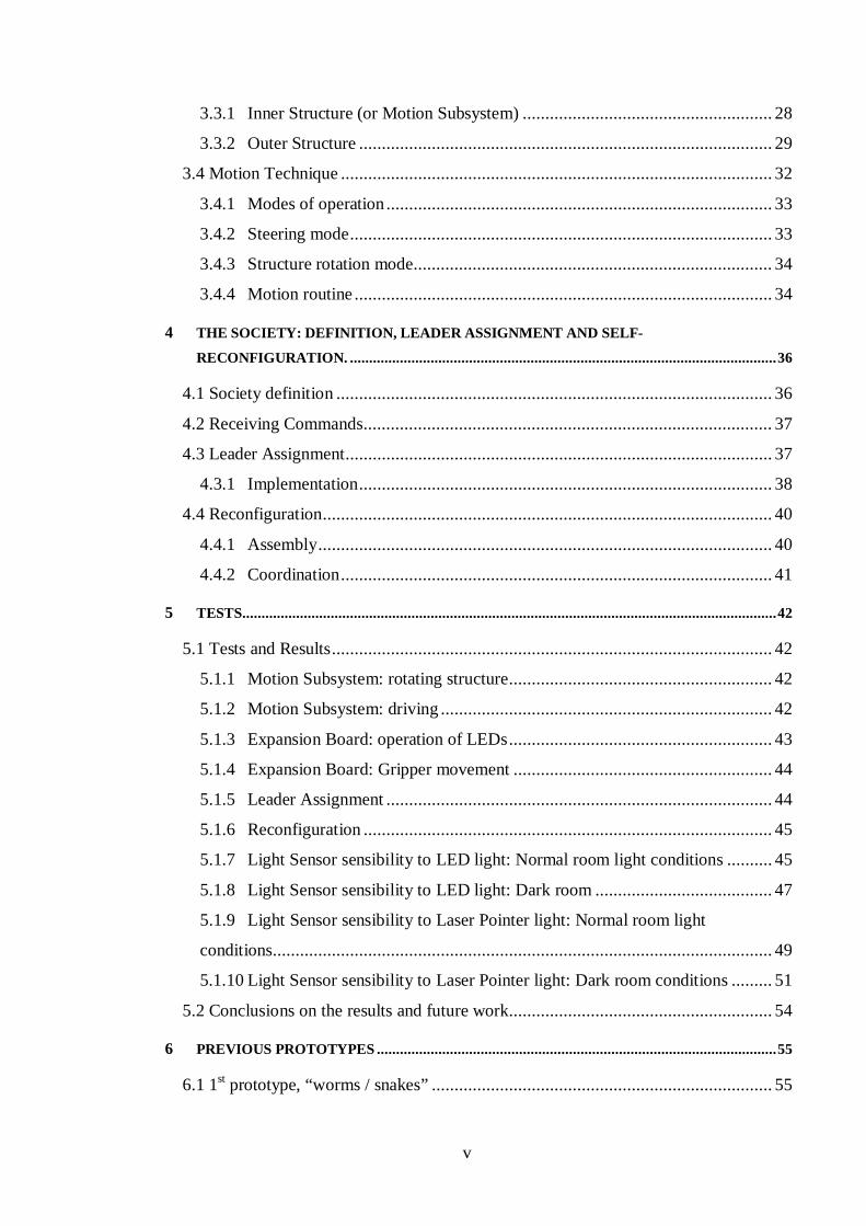
Fig. 19. NXT Module – Expansion board cable adapted to fit a regular header
connector. ....................................................................................................... 23
Fig. 20. Servo’s three wire cable connected to the expansion board. ........................ 24
Fig. 21. Ribbon cable connected to PORT A header of the expansion board (left) and
an LED connected to the ribbon cable (right). ................................................. 25
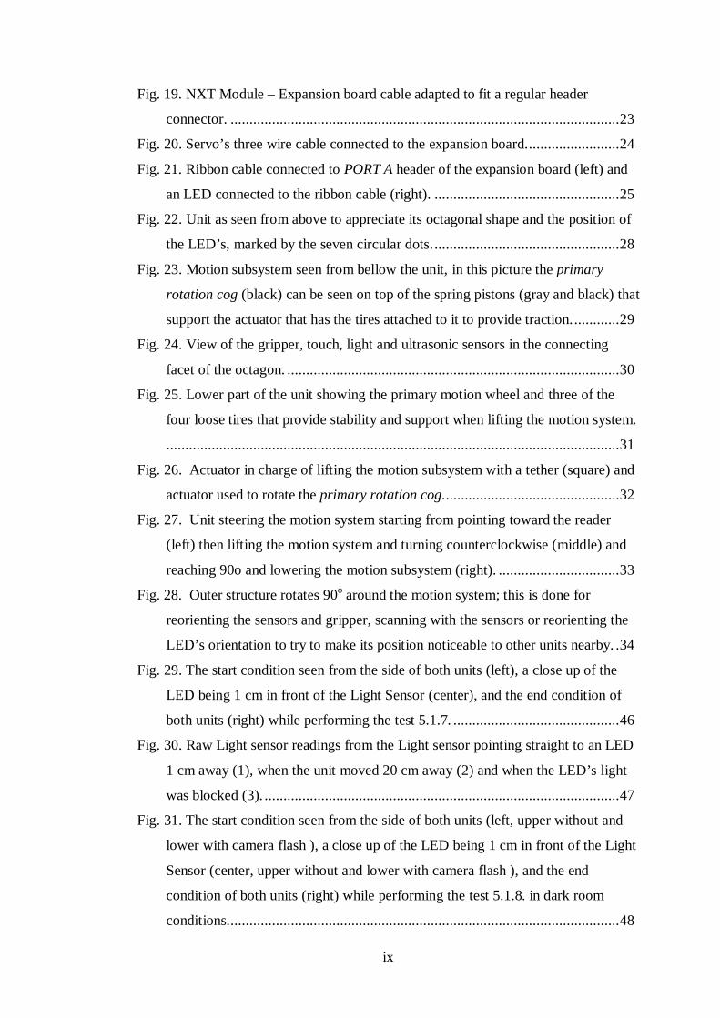
Fig. 22. Unit as seen from above to appreciate its octagonal shape and the position of
the LED’s, marked by the seven circular dots. ................................................. 28
Fig. 23. Motion subsystem seen from bellow the unit, in this picture the primary
rotation cog (black) can be seen on top of the spring pistons (gray and black) that
support the actuator that has the tires attached to it to provide traction. ............ 29
Fig. 24. View of the gripper, touch, light and ultrasonic sensors in the connecting
facet of the octagon. ........................................................................................ 30
Fig. 25. Lower part of the unit showing the primary motion wheel and three of the
four loose tires that provide stability and support when lifting the motion system.
........................................................................................................................ 31
Fig. 26. Actuator in charge of lifting the motion subsystem with a tether (square) and
actuator used to rotate the primary rotation cog. .............................................. 32
Fig. 27. Unit steering the motion system starting from pointing toward the reader
(left) then lifting the motion system and turning counterclockwise (middle) and
reaching 90o and lowering the motion subsystem (right). ................................ 33
Fig. 28. Outer structure rotates 90o around the motion system; this is done for
reorienting the sensors and gripper, scanning with the sensors or reorienting the
LED’s orientation to try to make its position noticeable to other units nearby. . 34
Fig. 29. The start condition seen from the side of both units (left), a close up of the
LED being 1 cm in front of the Light Sensor (center), and the end condition of
both units (right) while performing the test 5.1.7. ............................................ 46
Fig. 30. Raw Light sensor readings from the Light sensor pointing straight to an LED
1 cm away (1), when the unit moved 20 cm away (2) and when the LED’s light
was blocked (3). .............................................................................................. 47
Fig. 31. The start condition seen from the side of both units (left, upper without and
lower with camera flash ), a close up of the LED being 1 cm in front of the Light
Sensor (center, upper without and lower with camera flash ), and the end
condition of both units (right) while performing the test 5.1.8. in dark room
conditions........................................................................................................ 48

x
Fig. 32. Raw Light sensor readings from the Light sensor pointing straight to an LED
1 cm away (1), when the unit moved 20 cm away (2) and when the LED’s light
was blocked (3) and when unit using the light sensor rotated to point a dark
location(4). ...................................................................................................... 49
Fig. 33. The start condition seen from the side of both units (left), a close up of the
Laser pointer being 1 cm in front of the Light Sensor (center), and the end
condition of both units 20 cms from each other (right) while performing the test
5.1.9. in normal room illumination conditions. ................................................ 50
Fig. 34. Raw Light sensor readings from the Light sensor pointing straight to the
Laser pointer 1 cm away (1), when the laser pointer was moved 20 cm away (2),
when the Laser pointer’s light was blocked (3) and when unit using the light
sensor rotated to point a non Laser common lighted room location(4). ............ 51
Fig. 35. The start condition seen from the side of both units (left), a close up of the
Laser pointer being 1 cm in front of the Light Sensor (center), and the end
condition of both units 20 cms from each other (right) while performing the test
5.1.10. in dark room conditions. ...................................................................... 52
Fig. 36. Raw Light sensor readings from the Light sensor pointing straight to the
Laser pointer 1 cm away (1), when the laser pointer was moved 20 cm away (2),
when the Laser pointer’s light was blocked (3) and when unit using the light
sensor rotated to point a non Laser dark location(4). ........................................ 53
Fig. 37. Worm unit with its male connectors, female connectors and three degrees of
freedom. .......................................................................................................... 56
Fig. 38. Example of two units attached to each other. .............................................. 56
Fig. 39. Prototype one morphed into a four legged walker. ...................................... 57
Fig. 40. Prototype 2 and its connectors. ................................................................... 58
Fig. 41. A Sequence of how prototype 2 units would move as seen from the top
(above) and from the side (below). .................................................................. 59
Fig. 42. A group of Tile units that reconfigured themselves to climb over an obstacle,
all male connectors working on a 180o link. .................................................... 59

xi
Symbols and Abbreviations
API Application programming interface
CMS Centimeters
I2C Inter integrated circuit
LED Light emitting diode
NBC Next Bytes Codes
NXC Not Exactly C
PWM Pulse Width Modulated
TKK Teknillinen korkeakoulu
TWI Two wire interface
VI LabVIEW Virtual Instrument
xii
Foreword
This thesis shows the work of the author and his efforts to create a reconfigurable
multirobot society based in the LEGO Mindstorms NXT platform, proving the
platform’s capabilities in robotics development, and demonstrating the possibilities to
improve its performance by adding extra electronics, all this with the aim to test it as a
lowcost implementation for fast robotic prototyping. The work was performed at
Automation Technology Laboratory of Helsinki University of Technology, and the
society also took part of the MultiRobot Teaming Challenge of the robotics
workshop at the International Joint Conference on Artificial Intelligence on July 2009
in Pasadena, California.

1
Chapter 1
Introduction
In this new age of robotics, having robots perform simple tasks, is no longer good
enough. Recently, there has been a lot of research in trying to make robots more
versatile and able to perform more functions. This attempt avoid having an over
population of single purpose robots that will not only take much time and money to
create and develop, but will also saturate spaces with too many units, thus reducing
the overall performance of all units, and even humans, in their vicinity.
This introduction will present the term “Reconfigurable Multirobot Systems”, and
will define all of its aspects, next chapter will describe some examples of state of the
art systems currently being developed in different research centers across the world.
Chapters 3 will describe the Hardware and Software capabilities of the Robotic units
created by the author for this thesis work, and Chapter 4 will describe the operating
principles of the units when working together as a society. Chapter 5 will describe the
previous prototypes of units created by the author at the early stages of the thesis
work and the reasons why these prototypes were abandoned. Finally, Chapter 6 will
present the conclusions.
2
Two areas in the branch of robotics that have been growing in the last few years are:
Reconfigurable
This kind of robots can ‘transform’ or change their own structure or coordinate with
other robots to rearrange their position to create a larger structure, so that they can
perform multiple functions, sometimes even functions very different from each other,
and most importantly functions that were not thought of when the system was
designed.
Cooperative
Cooperative Mobile Robotics, are distributed robotics systems, that are characterized
by having a group of robots that interact with each other to reach a common goal.
SelfReconfigurable robotics systems have been, in the last two decades, trying to
reach a state where this kind of robotics can have a significant advantage over any
other robotic system. By fulfilling the promise of being Versatile, Robust, and Low
Cost, this kind of systems would be able to replace any other dedicated robotic
system, by reconfiguring and doing the same task, and being able to reconfigure at
any time to fulfill any other need that should arise, and all this with the same
hardware and software. Also, hardware could be mass produced to reduce the overall
cost of the system. An artistic image of such a system operating in space can be seen
in Fig1.

3
Fig. 1. Artistic example of a modular robotics group in a space application using a
Chain / Tree architecture, modules can be seen performing different tasks, such as
welding, replacing faulty units, assembly and more, from [11].
1.1 Multirobot Architectures
Reconfigurable multirobot systems can have many different types of architectures,
depending on the goal of each system, and the approach used in order to reach it.
Some of the different architectural features that need to be taken into account in order
to create or even analyze any multirobot system are described in the following
section.
1.1.1 Architectural Groups
Modular, self reconfigurable robotics can be classified into three groups depending on
their geometric arrangement of units.

4
Chain / Tree
The units in this architecture are connected in a string or tree topology, this
architecture can fold up to fill a space, but the overall structure is still serial see
example in Fig.2 (b). The strength of this architecture is that it can in principle reach
any point in a three dimensional space, making it suitable for many tasks, however
also increasing the complexity of the software for controlling it.
Lattice
In this schema, units are arranged and connected in a regular three dimensional
pattern, for example as a cube or square matrix or any three dimensional geometric
pattern. This schema can move several units in parallel, and the control algorithm can
be a simple, open loop system as any particular unit may only move to a limited
number of neighboring units or places as can be seen in Fig.2 (a). This results in a
very scalable solution.
Mobile
This kind of architecture does not have the units physically attached at all times, it’s
based on a number of mobile units that can move around large areas to, for example,
fuse together their sensor data and be able to cover larger areas. Part of it can hook up
and become a Chain or Lattice structure as needed.
Fig. 2. Types of Architectural groups Lattice (a), Chain/Tree (b), from [9]
5
1.1.2 Organizational Structure
The organizational structure of the group of robots can be either centralized or
decentralized, or a combination of the two, depending of the way the system is to be
controlled. It can be:
Centralized
This is a system that will depend entirely on a central unit (either a unit presently
among the group or a command center far from the actual position of the group) that
will command the entire group to reach the goal.
Decentralized
A system lacking a central controlling agent, each agent has the same level of
‘authority’ inside the group. This kind could be considered more challenging, as each
unit must have the computing power to analyze the situation, process the data and
take action.
Hybrid
A mixture of both schemas, a clear example being the kind of architecture where there
is no central control from the outside, and when a problem or situation requiring the
group to take action, a leading unit will arise and coordinate the rest to reach the goal.
1.1.3 Types of Units
The units in the group, both physically and in terms of computing power, can be
either Homogeneous or Heterogeneous. This decision will heavily influence the
complexity of the way units perceive each other and eventually how their interaction
is achieved.
Homogeneous
When all the units are exactly the same, they have the great advantage that every unit
knows the dimensions, capabilities and constraints of the rest of the units in the group,
and can know what to expect from them, as well as predict the unit’s position and

6
configuration at a given time. This is the most frequently used type of unit when it
comes to Modular reconfigurable units.
Heterogeneous
Units in the group could have different capabilities and physical construction. This
will increase the complexity of the interaction between units, but also offers the
advantage of having specialized units for some tasks.
1.1.4 Principle of operation
The way the units are moved when reconfiguring can be in one of the two following
ways:
Deterministic
Units are reconfigured by being directly manipulated to their destination, with a full
knowledge of the unit’s position and orientation at all times by either sensing or
calculating the position of the unit according to the position and movement over time,
as reconfiguration times can be guaranteed. Usually macro systems using either a
chain or mobile architecture use this kind of principle of operation.
Stochastic
In this classification type, when a reconfiguration is taking place, the units move
using statistical processes (e.g. Brownian motion). There are many paths the unit
could take to reach its destination, and there are usually many units that could take a
certain position, because of this the location of any unit not connected to the main
structure is impossible to know at any given time as is reconfiguration time. This kind
of reconfiguration is best for micro scale systems.

7
Chapter 2
State of the Art Systems
In this Chapter, some state of the art systems from many different kinds of
architectures, organizational structures and with different types of principles of
operation will be shown. In Table 1 there is a list of selfreconfigurable modular
systems that have been developed in the recent years from [11]; showing the class
they belong to (chain, lattice, mobile, stochastic or hybrid), the Degrees Of Freedom
(DOF, in this column the number of degrees of freedom of the units and weather they
move in 2D or 3D are shown), the author, where (affiliation) and what year they
were developed.
Table 1. List of some selfreconfigurable modular systems that exist today.

8
The systems described in the following sections are not the only systems or the most
representative ones, these are just the ones chosen by the author to give the reader an
impression of the kinds of systems that exist. For more information regarding this and
some more systems the reader could go to [11, 12, and 13].
2.1 Stochastic 3D (2005)
This system is an implementation of a self assembly and selfreconfiguration,
stochastic, homogeneous system in which no unit has any sort of locomotion; the
units rely on Brownian motions induced by the agitation of the surrounding medium.
These units also lack of any sort of inner energy supply, so they can draw power from
the growing system only when they are attached to it as described on [1].
As any system grows in number of units, it is very difficult and resource consuming
to keep track of every unit at any given time, so in order to be able to break the
current boundaries of size and number or units in a system, this stochastic method was
implemented in a simulation environment and later on two different physical three
dimensional stochastic modular robot systems that selfreconfigure in fluids.
The later of the two implementations was based on having small robotic cubes
submerged into a liquid and having a pump drawing the liquid out and putting the
liquid back in through some other inlets. This to create a flow in the fluid that would
make the units be drawn to it.

9
Fig. 3. A 2D representation of the principle of operation of the stochastic system
Each individual unit consists of a cube, with a hermaphroditic (it has no defined
genre) electrical connector, for power and control, and a set of valves that would be
opened and closed in order to attract the next unit to a certain given position as in
Figure 4 below.
Fig. 4. Experiment III of [1], depicting the mode of operation of this system from
being attached to the right side of the central cube at t 15 seconds, to reattaching to
the upper side or it almost 4 minutes later.

10
In Fig 4, an experiment is done to explain the way of operation. First a units is
floating free, and when successfully docking in a certain position (at t=15s), the
system is reconfigured by closing the valve that kept the cube there, and opening a
new one, this way releasing the cube to float free again and move in the substrate until
the flow forces it to attach again to the main unit after almost 4 minutes.
2.2 MTran III (2005)
MTran, short for Modular Transformer, is a lattice–chain hybrid, homogeneous,
distributed selfreconfigurable system that has been under development since 1998 by
AIST and TokyoTech [5].
This system is formed by small modules composed of two blocks, each half
cylindrical and half cubic with 3 possible connection surfaces (see Fig 5 for details)
Fig. 5. The MTran module with the full description of its connectors.
Each module has a particular gender. On one side, the male controls the connection
and is able to couple with any female side of another module, where the female part is
passive. Every unit has its own processing unit, and is intelligent enough to work with
the modules around it, which makes this a completely distributed autonomous system.

11
MTran tries to use the best of the Lattice and Chain architectures in order to reach a
system with a high level of adaptation, which is able to morph into different structures
and to move in many different patterns, such as a four legged walker, a snake and a
wheel (see Fig 6).
a) b) c)
Fig. 6. Different kinds of motion that can be achieved by the MTran system: four
legged (a) walker; (b) snake; (c) wheel.
2.3 Molecubes (2004 2008)
Molecubes is an Open Source, chain structured non homogeneous centralized system
built in the Cornell Computational Synthesis Lab, in 2004 [6]. This system aims,
among other goals, to prove selfreproduction and offers the promise of modular
robotics: to be a Versatile, Robust and Low Cost way to have a system that can
replace specialized machines with fixed bodies and functionalities.
12
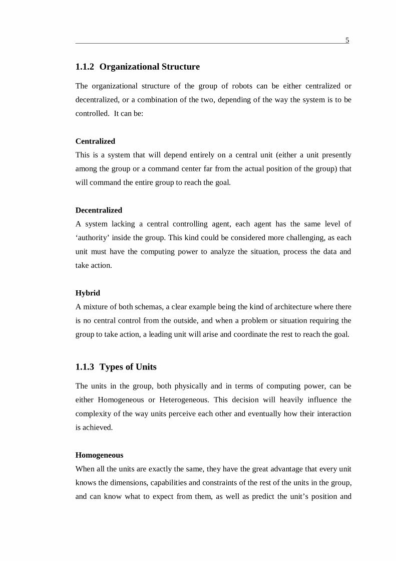
Fig. 7. Example of two Molecubes joined together
Molecubes are cube shaped units that have one degree of freedom across the cube’s
longest diagonal (see Fig 7). This system has many kinds of possible units that can
interact with each other, and in order to work, any assembled system will require at
least one controller unit and one battery module, and as many Molecubes and extra
modules (actuator modules or even passive modules) as needed to implement the
desired structure.
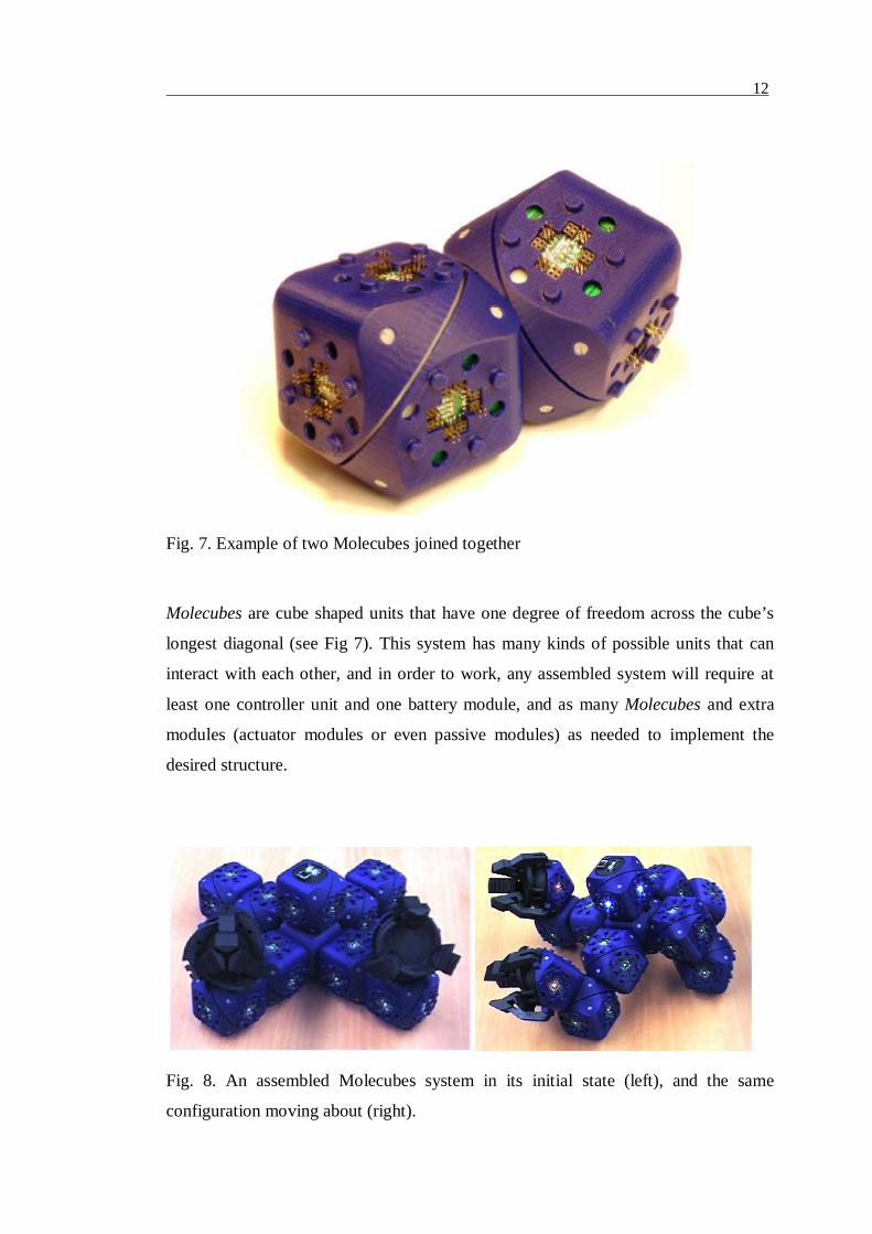
Fig. 8. An assembled Molecubes system in its initial state (left), and the same
configuration moving about (right).

13
In the first version of Molecubes, robotic self replication was demonstrated as shown
in Fig 9.
Fig. 9. The earliest version of Molecubes in a selfreplication run, where at the
start(0:00) there is one unit standing alone, and through the process it will take more
cubes and build a unit exactly like it.
This Open Source project provides all the hardware and software details so any
person can use their accumulated knowledge in this area and help boost its
development for more information please refer to [2,3].
2.4 Swarm Bots (20012005) – Swarmanoid (20062010)
Swarm Bots is a project is a homogeneous, decentralized system developed by the
Information Society Technologies framework programme of the European
Commission. The main objective of this project was to “study a novel approach to the
design and implementation of selforganizing and self assemblingartifacts” [8].

14
Fig. 10. SwarmBot going over a big gap.
Swarm robotics are inspired on the societies of insects, the way these societies are
very decentralized and have limited communication abilities among them, and they
rely on the use of local information, and emergent behaviors. In this particular
implementation a basic single unit is called “SBot”, while a group of units joined
together for a “SwarmBot” such as the one depicted in Fig 10. Each SBot is totally
autonomous unit (see Fig. 11 for a picture of a SBot prototype) and is comprised by
the following features:
• 116mm diameter size x 100 mm height.
• All terrain Treels (tracks and wheels) mobility system.
• One degree of freedom rigid arm with gripper
• Three degrees of freedom arm with gripper.
• IR proximity sensors
• Color LEDs around the body
• Light sensors around the body
• Force and torque sensors in the wheels
• 3 axis accelerometers
• Humidity sensors

15
• Temperature sensors
• Speaker and microphones
• Omni directional camera
Fig. 11. Single SBot unit prototype.
The basic behavioral capabilities that were achieved by the swarm at the time the
project ended were:
• Coordinated motion
• Hole/obstacle avoidance
• Passing over a hole
• Moving on rough terrain
• Aggregation
• Self assembly
• Functional SelfAssembly
• Adaptive division of labour
• Finding object / goal
• Cooperative transport

16
This project ended in 2005 and has been succeeded by the Swarmanoid project [14],
that is built on the results of the SwarmBots project, and now aims at creating a
heterogeneous distributed robotic system comprised of heterogeneous robots that
could be one of the three unit types: “Footbots”, “Handbots” or “Eyebots” and a
group of more than two units would comprise a “Swarmanoid”, see Fig 12 for some
pictures of the three kinds of units.
Fig. 12. A Footbot (Upper Left), a Handbot (Upper Right) and an Eyebot (Lower
Center), the three basic units that could comprise a Swarmanoid.
The Swarmanoid project puts forward an innovative way to build robots that can
interact and work inside manmade environments and it is the first to “study how to
design, realize and control a heterogeneous swarm robotic system capable of
operating in a fully 3dimensional environment” [14].

17
Chapter 3
STORM Unit: Hardware and Software
description
The Single Traction Octagonal Reconfigurable Machine (STORM) Units are the
robotic units that were created by the author to form the society described in Chapter
4, which was designed and built to become a Homogeneous, chain/tree society of
Mobile units that would move in the horizontal plane, this is, the units will drive
around in the floor and reconfigure themselves by driving around each other and
linking to create different shapes that, looked at from above will seem change in 2D.
In this chapter all their hardware, including sensors structure and connections, will be
described, as well as their software capabilities and motion technique.
3.1 Hardware
The units in the system are mostly comprised of LEGO Mindstorms NXT technology,
including the main controller unit, sensors, actuators and a set of LEGO pieces that
are used to create the mechanical structures. An expansion board was also developed
to add some external electronics and expand the capabilities on the LEGO NXT
system. All of these components will be described in the following subsections.
3.1.1 NXT Module
The NXT Module is the main controlling unit of the system; it has 4 input ports to
acquire data from sensors, and 3 output ports to be used for controlling the actuators,
as well as a USB port and Bluetooth wireless connectivity see Fig 13 for a digital
representation of this unit. Inside it there are two micro controllers:

18
• Main Processor: 32 bit ARM processor AT91SAM7S256 that controls the USB
and Bluetooth Connectivity, the LCD display, sound system and also controls the
COProcessor unit.
• Coprocessor: 8 Bit AVR processor ATMEGA48 that controls the input and
output ports, as well as the buttons on top of the unit.
Fig. 13. NXT Module
The NXT module uses an I2C Bus to communicate through all the input and output
ports to reach the actuators and sensors, and SPI to handle the Display and Bluetooth
communication.
3.1.2 NXT Sensors
There are 3 main sensors that the units use to get data from the outside world and
process it to be able to carry out their functions:
• Touch Sensor: to detect that the gripper has grasped an object, it works a
pushbutton and its output is Boolean value ONOFF.
• Light Sensor: to measure the presence of light and distinguish colors of objects,
based on the sfh3094 Silicon NPN Phototransistor that has a viewing angle of +
12o.See appendix for more details.
• Ultrasonic Sensor: to measure the distance from the unit to the next object in its
line of sight, it can measure up to 2.5 meters with a precision of up + / 3 cm, and
its field of view is 40 degrees per side. See appendix for more details.

19
Fig. 14. From left to right touch, light and ultrasonic NXT sensors.
3.1.3 NXT Actuators
Each unit uses three NXT Actuators that can rotate continuously as a DC motor and
also have an builtin rotation sensor that can measure both the angle and the amount
of rotations the actuator has performed in a certain direction see Fig 15 for an image
depicting one of these actuators.
Fig. 15. The NXT actuator.
3.1.4 Expansion Board
As the NXT Brick can only connect to up to 3 actuators through its output ports and
up to 4 sensors in the input ports, to expand these constraints, an Expansion board was
developed using the ATMega164P micro controller, which is has an I2C bus to be
able to connect to the NXT, as well as 32 programmable I/O lines, Real time clock,
Six PWM lines, two serial UARTS, analog comparators, and many other features that
make it suitable to expand the current capabilities of the NXT. In Fig 17 there is a
picture of an expansion board showing the ATMega164P microcontroller in the
middle.

20
Fig. 16. Expansion Board with the ATMega 164P.
This MCU board was first created by Antti Karjalainen, to use it for interfacing with
Zigbee wireless radios [4]. With a few modifications to original design it was adapted
to be able to communicate with the NXT via the I2C port of the microcontroller by
adding pullup resistors to the SDA and SCL lines and removing unnecessary headers.
The expansion board is currently used to add the following functionality to the units:
• Control a servomotor to drive the gripper that will enable the units to attach and
detach themselves from one another, see 3.1.5 for details and connections.
• Drive 7 LEDs that will be used to make a certain unit make itself noticeable to a
second unit and point the exact place where it wants this unit to approach and
attach itself to, see 3.1.6 for details on the LEDs characteristics and electrical
connections. For more details about the approach and attach sequences please
read section 4.4.1.
3.1.5 NXT – Expansion Board connection
The NXT module uses the I2C communication protocol to connect and exchange data
with the sensors and actuators, so this type of connection was chosen to be able to
communicate with the expansion board in a simple and very compatible way, such
that it would be connected to the NXT module as if it was another sensor.

21
As I2C was invented by Philips and as such is a proprietary protocol, the Expansion
board will be using then TWI (two wire interface) to connect to the NXT. TWI is
100% compatible with I2C but just cannot be called that way because of copyright
issues for more details about the communication protocol, way or operation and
software examples please refer to Appendix A.
The physical connector that the NXT module uses to connect to and from the sensors
and actuators is a special cable manufactures specially for LEGO. This is a six
conductors on six positions cable with a plug that is a variant of the RJ12 standard
plug, with the difference that the cable lock on the right side of the connector(see Fig
17), which makes any RJ12 connector or plug incompatible. For this reason the
board was not implemented with a hardware connector plug, and instead the cables
were cut on one end and crimped into another kind of connector that could connect to
a regular header as shown in Fig 18.
Fig. 17. Expansion Board with the ATMega 164P.

22
Fig. 18. NXT Module – Expansion board cable adapted to fit a regular header
connector.
The connector plug consist of a three wire female header connector (or four
depending on the version as one unit got a four pin header for testing and
expandability) that connects the blue, yellow and red cables of the original NXT
cables into the SDA, SCL and GND pins of the expansion board. SDA and SCL
(yellow and blue) connect directly to the “PWR” header pins 1 and 2 while the GND
(red) has a wire that goes from the female header of the cable connector to the male
header connector on pin 5 of the same header as shown on Fig 19.

23
Fig. 19. NXT Module – Expansion board cable adapted to fit a regular header
connector.
3.1.6 HiTec HS422 servo
The HiTec HS422 servo is a dual oilite bearing, indirect drive servo motor that
operates at speed of 0,21sec/60o, and provides 3.3kg.cm at 4.8 V which is the average
voltage that feed both the expansion board and the servo. It weights only 45.5g and
has a size of 40 x 20 x 36 mm. All these characteristics make it a very good option for
using this unit as the one driving the gripper of the units.
3.1.7 Servomotor – Expansion Board connection
The servomotor has a cable coming out that has three wires (VCC, GND and
SIGNAL in a female header connector) and is controlled by sending a Pulse Width
Modulated (PWM) signal with the desired position to the SIGNAL wire.

24
To connect it to the Expansion Board, the three pin female header connector must be
connected, the black (GND) wire to pin 9 of header “PORT D”, the red (VCC) wire to
pin 10 of the same header, and the yellow (SIGNAL) cable has a cable connecting it
to the male connector on pin 5 of again header “PORT D”, similar to the NXT cable
connection, see Fig 20 for details.
Fig. 20. Servo’s three wire cable connected to the expansion board.
3.1.8 PWM
A PWM is an efficient way of providing different amount of power to an electronic
device by switching power ON and OFF at certain intervals. In this particular
application, the servomotor is expecting a repeating square wave signal with a period
of 20 milliseconds and a varying duty cycle of 1 to 2 milliseconds, this is, a signal that
repeats itself every 20 milliseconds and that is pulled high (VCC) for 1 to 2
milliseconds every cycle. The difference in this amount of time the signal is high will
be interpreted by the motor as the position the shaft is required to have. A practical

25
example using the particular servo that it’s been used in the robot society for the
gripper is that if we send a repeating square signal with 1 millisecond duty cycle to
the motor, it will position the shaft at 90o from the center position, and when the duty
signal is changed to 2 milliseconds the motor will rotate the shaft to be at 90o from
the central position, this way opening or closing the gripper in our case.
3.1.9 Light Emitting Diodes
LEDs are connected to seven of the eight facets of the units, and are used to guide
another unit to connect in this particular facet. These LED’s are attached to the LEGO
structure and all connected together with a ribbon cable through a 220 ohm series
resistor to the power line (VCC) and to their designated pin in header number PORT
A of the microcontroller, see Fig 21 to see the way the ribbon cable is connected to
PORT A and also how an LED is connected to the ribbon cable.
Fig. 21. Ribbon cable connected to PORT A header of the expansion board (left) and
an LED connected to the ribbon cable (right).
These standard red LED lamps are 2 mm in diameter and have a viewing angle of
50oand and Intensity 20 mcd. In Fig 22 the position of the LED’s on the structure can
be appreciated.

26
3.1.10 Unit – Unit Connection
To communicate with another units, the NXT module has an embedded Bluetooth
communication radio, that can create a serial wireless connection between it and any
unit within a 10 meters distance in an “inside environment”)
The NXT module is prepared to be connected to 3 other NXT units simultaneously,
where one has to be the master of the 3 remaining units, in this mode the units send
messages that arrive at the destination unit’s mailbox as plain text messages. Besides
that, the module can also connect to another unit via a remote link and order the unit
to stop running the current program, run any other particular program, and monitor
the status of the incoming and outgoing data of the slave unit.
3.2 Software to Use
3.2.1 NXT Module
The NXT module has its own software “Mindstorms NTX”, which is a programming
suite based on Lab View, that provides basic functions to work with simple robots,
but is very limited when dealing with multiple units, behaviors and complex
structures. Besides this programming software, the NXT module can be programmed
in 3 main programming languages as described below.
• NXC: The Not eXactly C (NXC) high level language is similar to C and is
based on the low level Next Bytes Codes (NBC) that has an assembly
language syntax. The API is very close to C language and there is a good
documentation on the syntax and there are some examples for testing all the
functions. The NXC programs can be run in the Original firmware of the
NXT.
• leJOS: leJOS is a small java virtual machine that was ported in 2006 to work
with the NXT module. The API is extremely well documented and examples
are provided in the documentation. To be able to work with leJOS, the NXJ
firmware has to be downloaded into the NXT module.

27
• LabVIEW: National Instruments provides the “LabVIEW Toolkit for LEGO
Mindstorms NXT”, that has all the necessary tools for making advanced
programs in LabVIEW and can run the programs also in the original NXT
Firmware.
All the languages were downloaded and tested in order to choose the best one for the
application at hand. As NXC did not have much documentation about the I2C
communication implementation and the Bluetooth connection was also very basic and
complex to implement on a multi unit environment, it was decided not to use it for the
system implementation.
After some further testing and implementation of I2C and Bluetooth examples,
LabVIEW was chosen to be the programming language because it has available all
the LabVIEW tools that includes measuring units and reporting tools that will provide
an easier ontarget debugging and also a graphical way of representing the code to
better illustrate the algorithms to the reader in the following chapters.
3.2.2 AT Mega 164P
The ATMega164P can be programmed in two languages, Assembler and C, with
basically the same functionality, therefore, C was chosen for being simpler to
implement, and because of the existing subroutines and application notes that are
available be adapted to use the I2C to connect to NXT, and PWM to manage servo
motors.
3.3 Structure / Architecture
The structure of the units as seen from above resembles that of an octagon with its
eight facets as shown in Fig. 22. The body of the robot consists of two main body
parts referred to as the “Inner Structure or Motion Subsystem” and the “Outer
Structure”. These two parts of the unit are uncoupled and can be rotated totally
independent from each other. This will provide the units with direction of traction

28
independent from the structure orientation which is necessary for the units to be able
to attach to each other and still be able to orient the motion system to serve the newly
formed unit. Both subsystems will be described in the following subsections 3.3.1 and
3.3.2.
Fig. 22. Unit as seen from above to appreciate its octagonal shape and the position of
the LED’s, marked by the seven circular dots.
3.3.1 Inner Structure (or Motion Subsystem)
The inner structure is the one that provides the unit with the ability to have traction
and move with respect to the floor. This structure is made of a single traction LEGO
NXT actuator that is held in place by two spring pistons that are connected to the
primary rotation cog system that together with the tether attachment will be used for
steering / driving purposes and will be explained in section 3.4., see Fig 23 for a
picture detailing this subsystem.

29
Fig. 23. Motion subsystem seen from bellow the unit, in this picture the primary
rotation cog (black) can be seen on top of the spring pistons (gray and black) that
support the actuator that has the tires attached to it to provide traction.
3.3.2 Outer Structure
The outer structure is like a shell built around the motion subsystem and contains all
the environment sensing elements as well as the 7 LEDs and docking posts each one
on one facet of the octagon) that allow the attaching of another unit here, as well as
two actuators for motion control, sensors and the NXT unit. See Fig 24 for details. On
the connection facet of the octagon, the gripper, ultrasonic, light and touch sensors are
located all facing away from the unit (see Fig 24), and are used to detect and attach to
another unit in the society as well as sense the environment while moving in it.
30
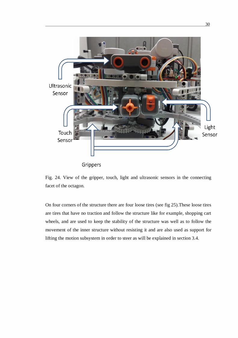
Fig. 24. View of the gripper, touch, light and ultrasonic sensors in the connecting
facet of the octagon.
On four corners of the structure there are four loose tires (see fig 25).These loose tires
are tires that have no traction and follow the structure like for example, shopping cart
wheels, and are used to keep the stability of the structure was well as to follow the
movement of the inner structure without resisting it and are also used as support for
lifting the motion subsystem in order to steer as will be explained in section 3.4.
31
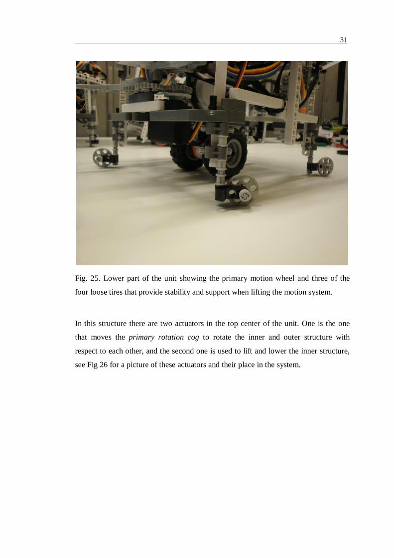
Fig. 25. Lower part of the unit showing the primary motion wheel and three of the
four loose tires that provide stability and support when lifting the motion system.
In this structure there are two actuators in the top center of the unit. One is the one
that moves the primary rotation cog to rotate the inner and outer structure with
respect to each other, and the second one is used to lift and lower the inner structure,
see Fig 26 for a picture of these actuators and their place in the system.

32
Fig. 26. Actuator in charge of lifting the motion subsystem with a tether (square) and
actuator used to rotate the primary rotation cog.
3.4 Motion Technique
In this prototype a novel motion technique was developed using a single actuator for
traction and two actuators to both steer the driving direction and change the
orientation of the outer structure independently. This enables two or more units to be
attached to each other and to steer their individual motion systems without putting any
kind of stress in the link, this way avoiding any undesired change in the orientation of
the joint structure that could occur while steering the individual motion systems. Units
33
are also able to totally disable their motion system to let other units do the driving and
save batteries without interfering or resisting the overall movement of the joint
structure.
3.4.1 Modes of operation
As described in section 3.3.1 the motion system is comprised of a single actuator, and
it can only move forward – backward, and is connected by a tether to another actuator
(see Fig 23) used to switch between steering and structure rotation modes, both modes
are described in the following subsections.
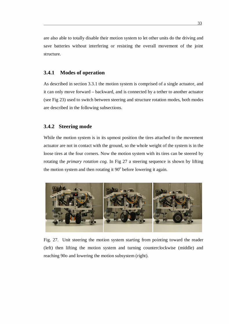
3.4.2 Steering mode
While the motion system is in its upmost position the tires attached to the movement
actuator are not in contact with the ground, so the whole weight of the system is in the
loose tires at the four corners. Now the motion system with its tires can be steered by
rotating the primary rotation cog. In Fig 27 a steering sequence is shown by lifting
the motion system and then rotating it 90o before lowering it again.
Fig. 27. Unit steering the motion system starting from pointing toward the reader
(left) then lifting the motion system and turning counterclockwise (middle) and
reaching 90o and lowering the motion subsystem (right).

34
3.4.3 Structure rotation mode
When the motion system is lowered the tires come in contact with the ground and the
spring pistons put most of the unit’s weight to the tires, so now in this configuration
activating the primary rotation cog would result in making the structure rotate around
the motion system and keep the steering direction firm when the motion system is in
action. See Fig 28 for a structure rotation photo sequence.
Fig. 28. Outer structure rotates 90o around the motion system; this is done for
reorienting the sensors and gripper, scanning with the sensors or reorienting the
LED’s orientation to try to make its position noticeable to other units nearby1.
3.4.4 Motion routine
To drive around and orient the structure to the desired position motion routines were
designed so that they always check the status of the rotation position state variable to
never exceed the amount of degrees (+/ 180o) that is safe to rotate one structure with
regards to the other. This variable is in zero when both structures are aligned (starting
1 To keep the cables from tangling and in this way preventing the primary rotation cog from rotatingproperly, and in worst case jamming it, the primary rotation cog should never rotate either the structureor the motion system more that +/ 180o from each other. This safety measure is implemented in themotion routine and is described in the following section 3.4.2.

35
condition calibrated by supervisor) so if this rotation was requested that would exceed
the safe values, the system would notice and calculate how to reach the same
orientation by rotating in the opposite direction.
As an example if the outer structure is + 90o displaced from inner structure and the
units need to rotate the structure + 135o instead of rotating + 135o that would be
closer to achieve (but it would take the displacement of structures to + 225) it would
rotate – 225o (displacement would be 135o) this way reaching the same sensor
orientation but without going over the 180o safety displacement amount.
A similar procedure would be applied to change the driving direction, a difference in
this case would be that if driving direction is more that 180o only change in forward
backward software would be needed and adjust the remaining degrees. As an example
if again the inner and outer structure are displaced by + 90o and a change in direction
of 135 is needed. Instead of moving the 135 and exceeding the safety value it
would rotate + 45 degrees and change the forward and backward direction
convention, this way keeping the count of the displacement degrees in a safe value of
+ 45 and preventing the system from getting jammed or loose accuracy because of
cog slippage.

36
Chapter 4
The Society: Definition, leader assignment
and selfreconfiguration.
Probably the first and most important step of creating a society is creating a structure
and the rules that the units will follow when a leader is to be assigned to take control
of the available units and issue orders to achieve a task at hand, in this case,
reconfiguration.
In this chapter a definition of Society will be presented, following by the leader
assignment and reconfiguration algorithms created by the author in his efforts to start
the foundations of a robot society.
4.1 Society definition
When many elements of similar characteristics are existing in the same area, they tend
to form societies, it happens with most living organisms in the planet. It can be from
very simple coexisting societies, where individuals hardly interact with each other, to
very tightly cooperative complex societies that are usually conformed of a large
number of individuals. A society as defined by Wikipedia is “… a body of individuals
of a species, generally seen as a community or group that is outlined by the bounds of
functional interdependence … ”
In this robotic context a society will be defined as a group of robots working in a
designated area that will discover the existence of more units of the same kind and try
to communicate with them in order to work together.

37
4.2 Receiving Commands
There are two ways in which the society or single unit would receive a command to
set a goal:
• When the system starts all the free units will be around looking to find a unit
that has a task in order to be the Master of the system and start working. So
when a new goal has been defined it will be send to a random unit, and by
having a goal it will start recruiting units for achieving it
• Master units will be able to receive commands from a commanding unit2 at all
times, so a sequence can be aborted or to change the goal. To achieve this, the
commanding unit connects to a random unit and asks for the Master name and
network identifier, so it then connects to the master unit and issues the order.
4.3 Leader Assignment
The creation of the team is essential to having a group of autonomous robots that is
versatile enough to choose it’s team members, designate a leader, detect when units
start malfunctioning or become lost (even the master), all this to make it autonomous
in the sense that it will not require human intervention at the beginning of the life
cycle, or when casualties occur.
Usually groups of robots start with predefined teams, and pre defined conditions that
are usually handmade, which somewhat take away the autonomy of the system, that’s
why an effective dynamic way of forming and maintaining team of robots is
necessary to be able to reach a state where the robots are truly autonomous and can
handle unforeseen situations as well as perform new tasks that were not defined when
the units where built.
2 At this time, commanding unit means a Bluetoothenabled computer that can send any unit in thesociety a command, but it is thought that in the future there could be other kinds of units in the societythat have the task of, for example, be issuing orders, having a more advanced view of a more complexgoal.
38
There has been some work before around this subject, in [7], a Pickup Team
Challenge is proposed to deal with this critical problem that remains unsolved, and
propose the treasure hunt domain for evaluating the performance of this pickup teams.
This treasure hunt consists of heterogeneous units that need each other’s abilities to be
able to search for treasure so the Team member selection relies heavily in the fact that
the units are heterogeneous, so this kind of approach would not work well in a small
homogeneous society.
4.3.1 Implementation
As this society needs to have a temporal leader to coordinate all the units while
working towards the goal. An algorithm to designate a leader among the units present
in the working area was developed based on the ideas of the author and is the
following:
As a free or master unit discovers other units close to it, it will pick the first one in its
discovery list, connect to it and check its working status. It could be that the unit
already is working for another Master unit; it is currently leading some units towards
a task (is a Master) or it is operating alone. Depending on this unit status the unit
asking will then either become master or slave of the newly discovered unit, or none
depending on the case shown in Table 2.

39
Table 2. Leader assignment cases and their outcome according to the status of boththe unit asking and the unit being asked.
Asking Unit Status
(AU)
Listening Unit Status
(LU)
Result
Working alone (with
known task)
Working alone (with/
without known task)
AU becomes Master of LU
Working alone
(without task)
Working alone (with
known task)
LU becomes Master of AU
Working alone
(without task)
Working alone (without
task)
Both stay as Free units and continue to
search for more units that could have a task.
Leading units3 Working alone (with /
without known task)
AU becomes Master of LU
Working alone (with /
without known task).
Leading units. LU becomes Master of AU.
Working Alone. Following another unit. AU gets the name and network identifier of
the master of LU and tries to locate it to ask
to join.
Leading units. Following another unit. AU gets the name and network identifier of
the master of LU to try to locate it and ask
for status.
Leading Units. Leading Units. If working for the same goal the one more
advanced in the reconfiguration process4
will become the Master unit and will acquire
the slaves5 of the newly acquired unit. If
they are both in the same stage the one
having higher number of slave units will
become the master unit and acquire the slave
units of the other master.
3 Leading units by default have a task defined.4 By more advance in the process it means that it requires less units to attach to the structure to reachthe desired form or shape.5 Slave units will not be asking other unit’s status.

40
4.4 Reconfiguration
4.4.1 Assembly
To get the units unto the desired configuration, the Master unit will move all the
needed units to attach to the main structure until it is completed. To achieve this is
will follow the following steps:
1. Check if there are units assembled and if the structure is reusable, this meaning
that some units are connected in a position that will be useful to reach the desired
configuration, if so those units will be retained and the rest will be ordered to
detach and move away from the main structure.
2. Prepare the main structure to be able to rotate around its axis. This will be
unique at every iteration of the assembly run as every time a unit is attached /
detached the master unit needs to take into consideration all the tires of the
attached units in order to choose the best motion technique6 to make the structure
rotate, and send the commands for the slaves to lift and rotate the tires
accordingly.
3. Point any unit not in the main structure to be pointing in the main structure’s
direction. To achieve this, the master unit will make the main structure, that could
be comprised of only the master unit, will turn all of its LED’s on and start
rotating around its axis, while having all the available free units rotate looking for
the source of light, and when any particular unit has reached of bested the desired
value in light intensity coming from the light sensor, all the rest will be ordered to
stop moving and the main structure and the candidate unit will refine their
position until the candidate is pointing straight to the main unit in the best
possible angle.
6 In this thesis work, the motion techniques are predefined to every step of the test reconfigurations, infuture work an algorithm to calculate this motion according to structure would need to be designed.

41
4. Align the candidate unit to the desired hook up place. Now that the free unit is
pointing towards the main structure in the best possible way, the main structure
will now turn off all the LED’s but the one in the place where it wants the
candidate unit attached, and will rotate until the candidate unit reports to have the
same value of light intensity coming from the light sensor as the one achieved in
the Point step.
5. Approach the master unit will order the candidate unit to approach the main unit
until it reaches hook up distance. The candidate unit will approach the main
structure driving in a straight line while having the light sensor have the same or
higher values than the ones acquired before until both the light and ultrasonic
sensor confirm the unit is in the desired position. In case the light sensor stops
detecting the LED, the unit will stop and report to the main unit, and in this case
the main unit will start turning the structure in an oscillatory motion until the
candidate detects the LED again so it can resume its approach.
6. Hook Up to the main structure by closing the linking tool until it firmly grasps
the connection point.
These steps will be repeated until the desired shape has been assembled or there are
no more available free units in the vicinity of the main structure.
4.4.2 Coordination
After all the units have been placed in the correct configuration by the Master, the
Master will coordinate all the units to move their tires to point in the same direction to
be able to move as a whole using as many motors as needed and putting the remaining
motors in neutral or lifting them to save energy.
At the point of completion of this thesis work, the tires of the two units closer to the
center of rotation where lifted and the remaining two units will use their motion
systems to drive the big unit like a tank using skid steering.

42
Chapter 5
Tests
5.1 Tests and Results
The following subsections will describe the tests that were performed on the motion
subsystem, the light sensor sensibility to the LED’s light, the light sensor sensibility
to laser pointers’ light, the Leader Assignment algorithm and the reconfiguration
algorithm.
5.1.1 Motion Subsystem: rotating structure
The first tests made were to refine the rotation between the Motion Subsystem and the
Outer Structure and to find the safe area in which the primary rotation cog could
rotate freely without getting stuck.
For this test simple routines were programmed to remote control the motors from
LabVIEW and were tested an all four readily assembled units.
Results
After calibrating all units and making some changes to the mechanical structure, all
four units were able to rotate the Outer Structure +/ 180 degrees from the Motion
Subsystem without getting stuck.
5.1.2 Motion Subsystem: driving
Motion routines were implemented according to the Motion Routine described in
section 3.4 to test that the unit could move around an area with a the combination of
the three main actuators. The following routines were implemented on all four units:

43
• Rotate Right: This routine would rotate the outer structure 90o from the
motion subsystem using the primary rotation cog in a clockwise direction (as
the motion subsystem is in contact with the ground the structure rotates and
the motion subsystem remains static), then lift the motion subsystem by
rotating the lifting actuator 180o, rotating again the outer structure 90o from
the motion subsystem using the primary rotation cog in a clockwise direction
(as the motion subsystem is not in contact with the ground the structure
remains static and the motion subsystem rotates freely) and then rotating the
lifting actuator 180o to lower the motion subsystem and be in the same
configuration as in the beginning but facing both outer structure and motion
subsystem 90o from the initial position.
• Rotate Left: The same as Rotate Right but rotating the primary rotation cog
in counterclockwise direction.
• Move Forward: Rotate the motion subsystem actuator that is attached to the
tires’ “forward”.
• Move Backward: Rotate the motion subsystem actuator that is attached to the
tires’ “backwards”.
Results
By using these routines the system was tested and the height of the four loose tires
that support the outer structure with regards to the ground was calibrated to its
optimal state. Also the system was debugged and some minor hardware changes were
made to allow the system to perform these tasks.
5.1.3 Expansion Board: operation of LEDs
Sample routines were created to test that the operation of the LEDs matched the
desired functionality, and that the software written for the ATMEGA164P was
working properly when integrated into the system.
Results
Both the LabVIEW routines and the software to run the ATMEGA164P were
debugged in these tests and as a result LabVIEW virtual instruments were created to

44
turn the LEDs ON and OFF via I2C. Also the LED and I2C routines in the
ATMEGA164P were finalized.
5.1.4 Expansion Board: Gripper movement
Sample routines were created to test that the operation of the Servo control matched
the requirements, and that the software written for the ATMEGA164P was working
properly when integrated to the system.
Results
The routines for moving the servo motor by changing the duty cycle of the PWM
signal as described by section 3.1.8 were working properly and the final version of the
code for the ATMEGA164P was finalized and uploaded to all Expansion Boards.
5.1.5 Leader Assignment
The leader assignment algorithm was implemented as set of LabVIEW virtual
instruments as was tested independently from all other software. In this subsection
tests and results for this algorithm will be shown.
A set of two LabVIEW virtual instruments (.vi files) were implemented to test the
Leader Assignment algorithm. LAF.vi was run in units with the role of “Free units”,
and LAM.vi was run in the “Master units” (see appendix E.1 for the software
implementation of LAF), and tests were made with units in different stages with the
following results:
• All “Free” units without task were running the same software LAF and they
scanned all units, and at the end they all remained free units.
• Three Units were “Free” running LAF.vi and one was “Master” running
LAM.vi, at the end of the run the “Master” remained being Master and the
three “Free” units had “Slave” status with the Master’s id on the file
“MasterID”.

45
• One “Free” unit running LAF connected to a “Slave” (slave units are not
looking for more units because they already have a Master) and got the ID of
the Master.
5.1.6 Reconfiguration
To be able to test the reconfiguration algorithm, virtual instruments Slave.vi and
Master.vi were developed to test the approach of a unit by command of the Master
unit, and then closing the gripper to link (see appendix E.2 for the software
implementation of Slave.vi).
Results
Extensive testing had to be performed in different natural lighting conditions, as the
light sensor was not behaving as expected. In regular daylight conditions the
algorithm acted erratically as the light sensor was heavily influenced by the natural
light from the windows and the room lamps. In dark room conditions during
nighttime, results improved quite drastically, which led to performing tests 5.1.7 to
5.1.10.
5.1.7 Light sensor sensibility to LED light: Normal room light
conditions
A LabVIEW routine was implemented to be able to see the intensity of the light
detected by the light sensor in realtime plotted on a scope and see the difference in
intensity with regards to distance.
This test consisted on having two units standing one behind the other with the light
sensor one centimeter away from the back side LED of the unit on front, and then
having the unit in front move forward 20 centimeters using the move forward routine,
and record the readings. In Fig. 29 the start and end conditions can be appreciated as
well as a closeup of the LED being in front of the light sensor.

46
Fig. 29. The start condition seen from the side of both units (left), a close up of the
LED being 1 cm in front of the light sensor (center), and the end condition of both
units (right) while performing the test 5.1.7.
Results
The readings were recorded and are shown in Fig. 30, where we can see the raw
values received from the light sensor while running the test and seeing that at the start
the raw value received by the sensor is of about 620 units in point 1, and then when
the unit moved to be 20 centimeters farther the reading became around 700 units in
point 2, and is about the regular value of the room as can be seen when the LED light
is blocked from the sensor in point 3.
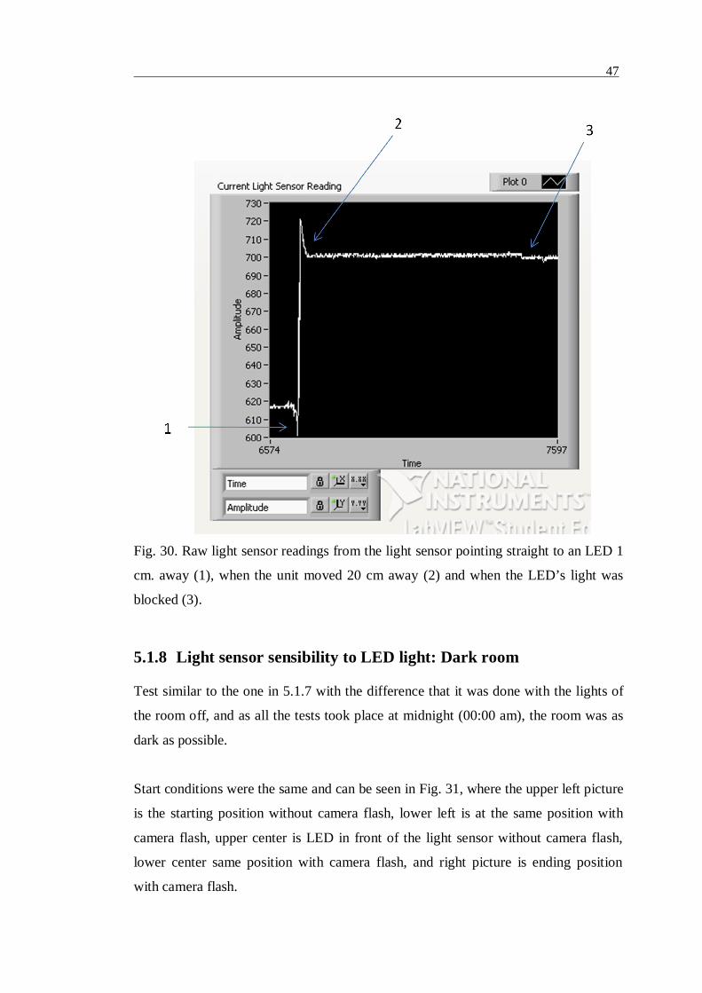
47
Fig. 30. Raw light sensor readings from the light sensor pointing straight to an LED 1
cm. away (1), when the unit moved 20 cm away (2) and when the LED’s light was
blocked (3).
5.1.8 Light sensor sensibility to LED light: Dark room
Test similar to the one in 5.1.7 with the difference that it was done with the lights of
the room off, and as all the tests took place at midnight (00:00 am), the room was as
dark as possible.
Start conditions were the same and can be seen in Fig. 31, where the upper left picture
is the starting position without camera flash, lower left is at the same position with
camera flash, upper center is LED in front of the light sensor without camera flash,
lower center same position with camera flash, and right picture is ending position
with camera flash.

48
Fig. 31. The start conditions seen from the side of both units (left, upper without and
lower with camera flash), a close up of the LED being 1 cm in front of the light sensor
(center, upper without and lower with camera flash), and the end condition of both
units (right) while performing the test 5.1.8. in dark room conditions.
Results
The readings were recorded and are shown in Fig. 32, where we can see that the start
the raw value received by the sensor is of about 575 units in point 1, and then when
the unit moved to be 20 centimeters farther the reading became around 870 units in
point 2, and when the LED light is blocked from the sensor in point 3 the value
becomes 875, and the last point is where the LED was uncovered again and the unit
with the light sensor turned 45 degrees clockwise to point into a dark area that has
around the same value as 875, but been reached gradually as the unit rotates to point
away.

49
Fig. 32. Raw Light sensor readings from the Light sensor pointing straight to an LED
1 cm away (1), when the unit moved 20 cm away (2), when the LED’s light was
blocked (3), and when unit using the light sensor rotated to point a dark location (4).
5.1.9 Light sensor sensibility to Laser Pointer light: Normal room
light conditions
Test similar to 5.1.7 in lighting conditions, with the difference that in this test, instead
of the LED light mounted on a STORM unit, the test would be done with a laser
pointer at about the same height so that the its light would hit straight into the light
sensor. In Fig. 33 the setup with the starting and ending conditions and the closeup of
the laser pointing directly into the light sensor can be seen.

50
Fig. 33. The start condition seen from the side of both units (left), a closeup of the
laser pointer being 1 cm. in front of the light sensor (center), and the end condition of
both units 20 cms. from each other (right) while performing the test 5.1.9. in normal
room illumination conditions.
Results
The readings were recorded and are shown in Fig. 34, where we can see the raw
values received from the light sensor while running the test and seeing that at the start
the raw value received by the sensor is of about 100 units in point 1, and then when
the unit moved to be 20 centimeters farther the reading stayed around 100 units in
point 2 (some amount of noise can be seen because of the movement to move the
laser pointer 20 cms. away), in point 3 the laser pointer light is blocked and the value
raised to around 720 units, and then the laser light is unblocked again so that then the
unit can turn around 45 degrees into common room lighting in point 4, that comes to
around 700 units.

51
Fig. 34. Raw Light sensor readings from the light sensor pointing straight to the laser
pointer 1 cm away (1), when the laser pointer was moved 20 cm away (2), when the
laser pointer’s light was blocked (3) and when unit using the light sensor rotated to
point a nonlaser commonlighted room location (4).
5.1.10 Light Sensor sensibility to Laser Pointer light: Dark room
conditions
Test similar to the one in 5.1.9 with the difference that it was done with the lights of
the room off, and as all the tests took place around midnight (00:00 am) the room was
as dark as possible. In Fig. 35 the setup with the starting and ending conditions and
the closeup of the laser pointing directly into the light sensor can be seen, only this
time the pictures were taken in the dark room with the camera flash activated.

52
Fig. 35. The start condition seen from the side of both units (left), a closeup of the
laser pointer being 1 cm in front of the light sensor (center), and the end condition of
both units 20 cms from each other (right) while performing the test 5.1.10. in dark
room conditions.
Results
The readings were recorded and are shown in Fig. 36, where we can see that the start
the raw value received by the sensor is of about 100 units in point 1, and then when
the unit moved to be 20 centimeters farther the reading stayed in 100 units, just there
was some small noise that had to do with the moving of the laser as shown in point 2,
and when the LED light is blocked from the sensor in point 3 the value becomes 875,
and the last point is where the LED was uncovered again and the unit with the light
sensor turned 45 degrees clockwise to point into a dark area with the same value 875
in point 4, that is reached with some noise but in a shorter time with a steeper change
of values.

53
Fig. 36. Raw light sensor readings from the light sensor pointing straight to the laser
pointer 1 cm away (1), when the laser pointer was moved 20 cm away (2), when the
laser pointer’s light was blocked (3) and when unit using the light sensor rotated to
point a nonlaser dark location (4).

54
5.2 Conclusions on the results and future work
The implementation of the Leader Assignment algorithm in LabVIEW proved to be a
good way to designate a leader based on a case structure with all the possible options,
and units clearly behave respond the way they should. It was tested with the four units
that were constructed and in the different roles and stages. For future work it would
need to be tested on a larger scale system and add priorities among Heterogeneous
units for example.
While implementing the reconfiguration algorithm it was proven that this approach
could provide a viable solution, if better LED lamps and/or sensors are used. The
major problems were that it was designed under the assumption of an ideal, noisefree
environment and the sensitivity of the light sensor was overestimated. Many tests
were done, but the light sensor proved to be very sensitive to ambient noise such as
natural outside light as well as white light from the room lamps and a combination of
this problem with the LED lamp’s diffused light beam took a high toll on the system.
The best results with the LED’s were acquired late at night with the system in total
darkness, and even then the LED’s 50o viewing angle make the system perform poorly
in the approach when the distance is greater than 20 cms. The results of the tests 5.1.9
and 5.1.10 show clearly that the laser beam from the laser pointers is perfectly
identified by the light sensor but has to be pointing directly into the sensor to be
successful. For future work trying more powerful LED lamps with smaller viewing
angle or adapting laser pointers to be integrated into the system is necessary. Also,
adding more LEDs and/or the use of color coding as seen in Swarmbots [8] would
definitely improve the existing system. Fusing the sensor information of the ultrasonic
sensor with the light sensor could also improve the unit’s ability to attach
successfully.

55
Chapter 6
Previous Prototypes
Before reaching the actual design, many prototypes with different functionality were
built and tested, but were discarded due to a major problem mostly in the physical
implementation, the two most important ones are described in this chapter, their
concept and more importantly why there were abandoned.
6.1 1st prototype, “worms / snakes”
The first prototype was intended to have wormlike units that would have 3 degrees of
freedom and would have slots all over the body so another unit could attach to it by
knowing the orientation of a certain unit regarding the others. Each unit could attach /
detach from another with the male connectors in the front or back (or the “head and
the tail) and attach to the female connectors all over the sides of other unit, see Fig 37
for details.

56
Fig. 37. Worm unit with its male connectors, female connectors and three degrees of
freedom.
Using geometry and the three degrees of freedom, the unit would move from one slot
to the next and reach the desired position. In Fig 38 two units are connected, the “n”
shaped unit on top has both its male connectors attached to the female connectors of
the unit that is totally straight.
Fig. 38. Example of two units attached to each other.
Male
connectors
Female
connectors
Degrees of
freedom

57
This system was intended to have the capability to morph the system into a four
legged walking robot like the one illustrated in Fig. 39.
Fig. 39. Prototype 1 morphed into a four legged walker.
6.1.1 Planned Control
The control of this society was planned to be using the control theory of robotic arms,
using link matrixes per every degree of freedom and calculate the transformation
matrix for every movement, and even Jacobians to control the velocities as described
in [15]. Although heavy to process, the NXT units could handle them.

58
6.1.2 Problems
While building this prototype, many problems arose regarding the physical
implementation as the NXT module and the actuators are very big. Therefore, the
resulting unit needed to be very large in order to have the necessary length to
width/height size ratio. Another problem was that to be able to connect the unit from
both ends, too many sensors and extra motors were needed, as building a connector
with this functionality is very complex.
6.2 2nd prototype, “Tiles”
The second prototype was designed to have units in the form of square tiles with two
male and two female connectors each. In Fig. 40 these connectors are shown, the
hollow gray squares are the female connectors and the filled gray squares are the male
connectors.
Fig. 40. Prototype 2 and its connectors.
These units would connect the male connector to the female connector of a
surrounding unit and then pull the connector back to make bring the two units
together along with other units that could be attached to other connectors on any of
the two units. As an example, in Fig 41 there is a sample sequence of how the units
could move in the horizontal plane, here the black figures indicate a male connector
bound to a female one.

59
Fig. 41. A Sequence of how prototype 2 units would move as seen from the top
(above) and from the side (below).
Having a large number of tile units would allow the system to move around a physical
area regardless of the shape of the terrain, and to climb obstacles larger in size than a
single unit, as shown in Fig. 42
.
Fig. 42. A group of Tile units that reconfigured themselves to climb over an obstacle,
all male connectors working on a 180o link.
6.2.1 Planned Control
This society would also be controlled by the master by the use of transformation
matrixes and Jacobians as the 1st prototype in the last chapter..

60
6.2.2 Problems
This prototype’s first major problem came when trying to make the male connectors
be able to push the link beyond 265o as the connector had to be very large and with
some sort of telescopic expandable / retractable mechanism, that proved to be very
difficult to achieve with Lego Mindstorms equipment.
The second problem arose when trying to make the link have more than one unit “in
the air”, that is, to be moving more than two units up from the ground to, for example,
try to reach on top of an obstacle. When trying this configuration, the links involved
had too much tension and the Lego pieces began to separate as the weight of the two
units was too much for the structure to bear without disassembling. The motors could
easily lift the weight but the structure was unable to stand in mid air in a stable
condition, to do so would require a lot more pieces to be attached, and the system’s
weight would increase in a manner that the problem would be unsolvable with the
available equipment. Because this would be needed for the system to be able to reach
its designed goals the prototype had to be abandoned.
61
Chapter 7
Conclusions
Right now there are some systems that have been able to achieve solid goals, like
Stochastic 3D, MTran, Molecubes and Swarmbots that, each in their own categories,
will surely become cornerstones in fulfilling the promise of one day becoming:
Versatile, Robust and Low Cost systems, and by doing so they will have a great
impact everywhere, especially in the areas of:
• Space Exploration: having less amount of mass sent up, and being able to
use it in so many ways (as the units will be able to adapt and do tasks not
foreseen before they happen) will definitely be a boost.
• Pollution / Environmental: Having a single system instead of more and more
robots for all the different needs, will definitely impact in needing less and
less resources from our planet being consumed as well as saving energy too.
In addition to the growing problem of saturating our living spaces with more
and more machines lying around, which will eventually lead us to have even
traffic control systems in our own homes.

62
Creating a robot society is very complex and time consuming, especially because is
an area of robotics that it’s on the early stages of development. With this thesis work,
creating a prototype society made of LEGO Mindstorms was achieved successfully,
and although some problems arose and the system could not selfreconfigure itself
with high accuracy as it was desired, some good results have come from it, such as:
• Prototyping with LEGO Mindstorms is a fast way to prototype mechanical
systems and, with basic algorithms test the viability and stability of the system
in order to be able to decide if to continue to put more time effort and money
on the proposed design, to know the areas where more improvements are
needed, or if to totally abandon the idea.
• The Lego Mindstorms NXT’s set can be upgraded with the expansion board
and many sensors and / or motors can be easily added so the system is not
fully dependant on LEGO’s constrains and specifications.
• The single traction motion technique described in section 3.4 was tested and
showed to be a good option to use with reconfigurable systems that need to
have the structure independent from the traction.
• The Leader assignment algorithm was successfully implemented in LabVIEW
and could be the base of a more complex leader assignment algorithm for
Heterogeneous societies.
• Initial testing was done on the approach for mobile reconfiguration and with
proper upgrades the system could have a bright future.
• The robot society was used to test the coordination algorithms of Jürgen
Leitner’s thesis work [17], and took part of the Multirobot Teaming challenge
of the International Joint Conference on Artificial Intelligence (IJCAI 09)
[18].

References
[1] White P., Zykov V., Bongard J., Lipson H. (2005) Three Dimensional Stochastic
Reconfiguration of Modular Robots, Proceedings of Robotics Science and Systems,
MIT, Cambridge MA, June 810, 2005.
[2] Zykov V., Chan A., Lipson H., (2007) Molecubes: An OpenSource Modular
Robotics Kit, IROS2007 SelfReconfigurable Robotics Workshop.
[3] Zykov V., William P., Lassabe N., Lipson H., (2008) "Molecubes Extended:
Diversifying Capabilities of OpenSource Modular Robotics", IROS2008 Self
Reconfigurable Robotics Workshop, accepted.
[4] Karjalainen A, (2009) Wireless sensor network platform for the use of
assistive home automation applications, Helsinki University of Technology Masther
Thesis.
[5] MTran web page http://unit.aist.go.jp/is/dsysd/mtran3/what.htm
[6] Molecubes project web page http://www.molecubes.org/
[7] Jones G A, Browning B, Dias M B, Argall B, Veloso M & Stentz A (2006)
Dynamically Formed Heterogeneous Robot Teams Performing TightlyCoordinated
Tasks, Proceedings of the 2006 IEEE International Conference on Robotics and
Automation Orlando, Florida May 2006.
[8] Swarm bots project webpage, http://www.swarmbots.org/
[9] S. Murata, and H. Kurokawa, SelfReconfigurable Robot: ShapeChanging
Cellular Robots Can Exceed Conventional Robot Flexibility, IEEE Robotics &
Automation Magazine March 2007.
[10] Kamimura A, Kurokawa H, Yoshida E, Murata S, Tomita K and Kokaji S,
Automatic Locomotion Design and Experiments for a Modular Robotic System,
IEEE/ASME Transactions on Mechatronics, Vol. 10, Issue 3, pp. 314325, 2005.
[11] Yim M, Shen WM, Salemi B, Rus D, Moll M., Lipson H, Klavins E, Chirickjian
G S, (2007) “Modular Selfreconfigurable robotic systems”, IEEE Robotics and
Automation Magazine, Vol. 14 No. 1, pp. 4352.
[12] Multi robot systems classification on coordination

[13] Yim M, White P, Park M, Sastra J Modular SelfReconfigurable Robots (2009),
www.springer.com/9780387758886.
[14] Swarmanoid project webpage, http://www.swarmanoid.org
[15] Craig J, Introduction to Robotics mechanics and control, third edition, Prentice
Hall, Chapter 2 – 5 , 2005
[16] http://hri2008.org/
[17] Leitner J, MultiRobot Formations for Area Coverage in Space Applications
(2009)
[18] http://ijcai09.org/

Appendix A
TWI Communication Protocol from ATmega164P datasheet


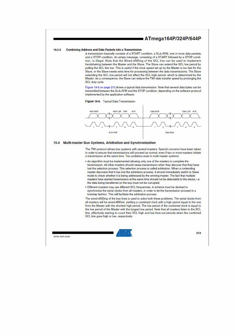
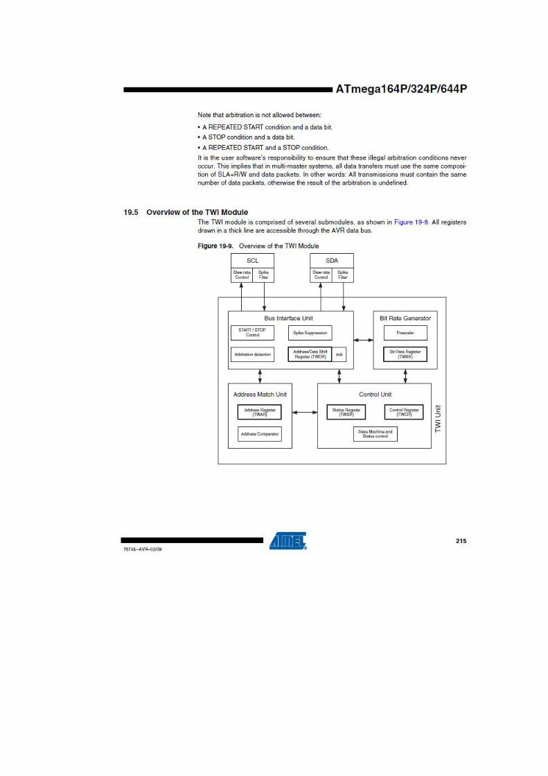
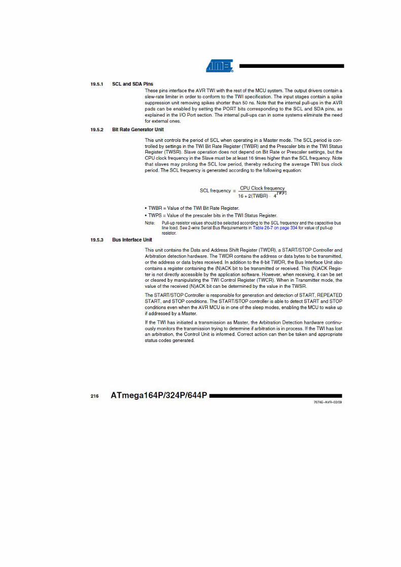


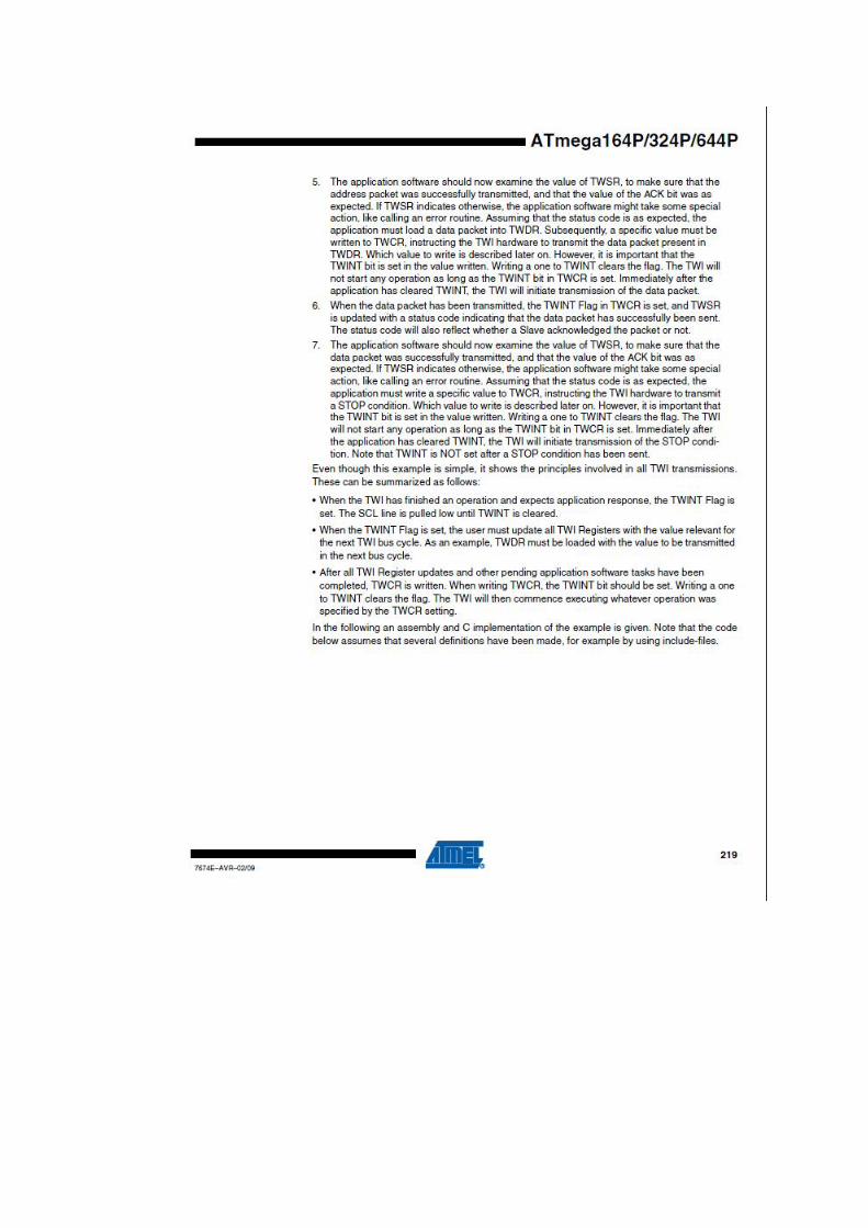


Appendix B
B.1 Ultrasonic sensor piezo sender and receiver
from http://www.kelei.com/ecp4.htm

B.2 Light Sensor Phototransistor

Appendix C
Expansion Board
C.1 ATMega 164P

Appendix D
LabVIEW Virtual Instruments
E.1 LAF.vi
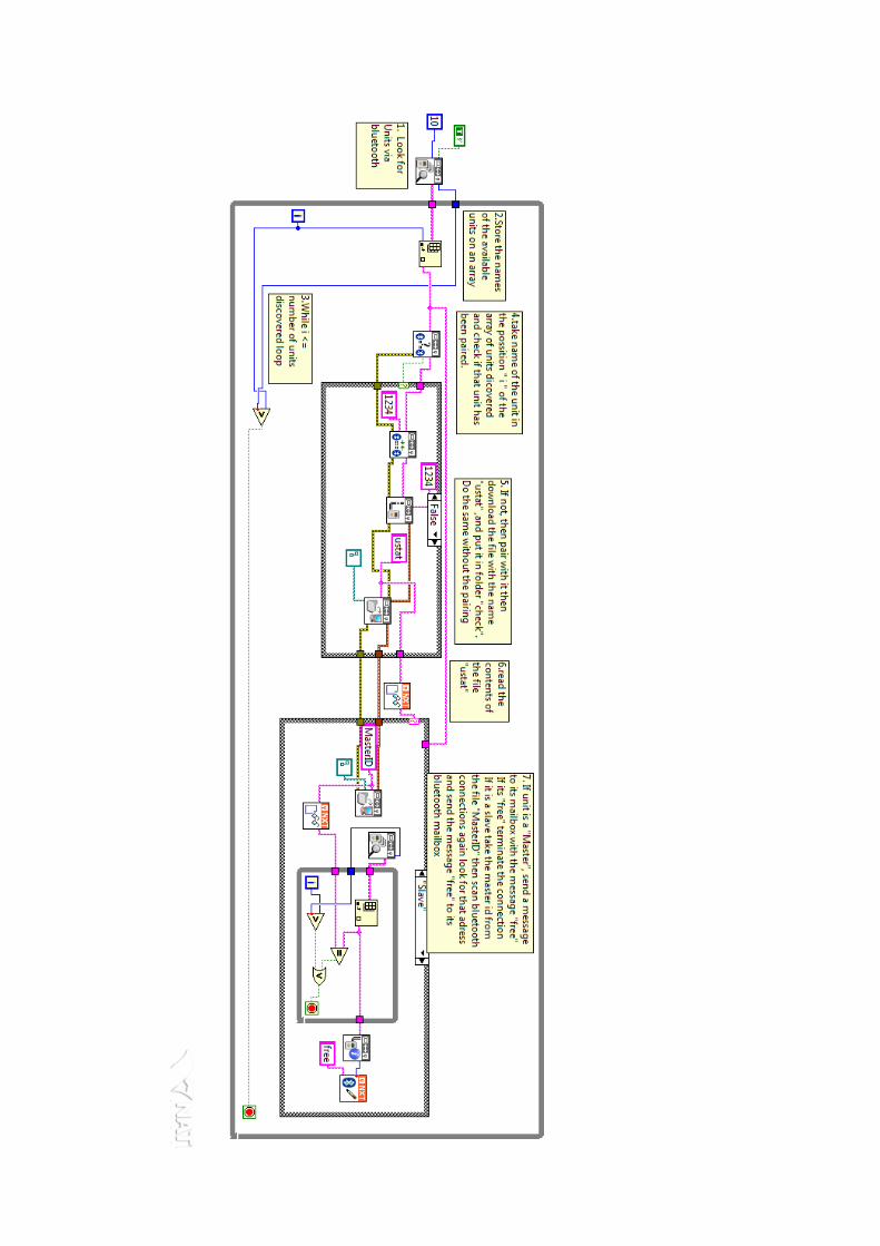

E.2 slave.vi when in approach mode