A Miniaturised Space Qualified MEMS IMU for Rover...
32
A Miniaturised Space Qualified MEMS IMU for Rover Navigation “Multi Wafer Hybrid Integration: Rover IMU 1” Presented by John Cornforth and Felix Rehrmann at 11th Symposium on Advanced Space Technologies in Robotics and Automation ESTEC 11 th – 14 th April 2011
-
Upload
nguyentram -
Category
Documents
-
view
224 -
download
0
Transcript of A Miniaturised Space Qualified MEMS IMU for Rover...

A Miniaturised Space Qualified MEMS IMU
for Rover Navigation
“Multi Wafer Hybrid Integration: Rover IMU 1”
Presented by John Cornforth and Felix Rehrmann
at 11th Symposium on Advanced Space Technologies in Robotics and Automation
ESTEC 11th – 14th April 2011
2
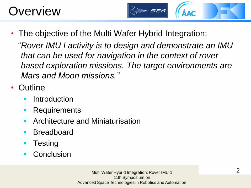
Overview
• The objective of the Multi Wafer Hybrid Integration:
“Rover IMU I activity is to design and demonstrate an IMU
that can be used for navigation in the context of rover
based exploration missions. The target environments are
Mars and Moon missions.”
• Outline
Introduction
Requirements
Architecture and Miniaturisation
Breadboard
Testing
Conclusion
Multi Wafer Hybrid Integration: Rover IMU 1
11th Symposium on
Advanced Space Technologies in Robotics and Automation

3
Partners
Multi Wafer Hybrid Integration: Rover IMU 1
11th Symposium on
Advanced Space Technologies in Robotics and Automation
Prime Contractor
Architecture Design
Miniaturisation
Mock-Up Testing
AAC Microtec
Uppsala
Sweden
Funded by ESA, Allocated in the Automation and Robotics Section:
Rate Sensor
Architecture Design
Breadboard Design &
Manufacture
Systems Engineering &
Assessment Ltd (SEA)
Bristol
England
Requirements
Sensor Data Processing
Breadboard Testing
German Research Centre
for Artificial Intelligence
Robotics Innovation Centre
Bremen
Germany

4
Introduction
Multi Wafer Hybrid Integration: Rover IMU 1
11th Symposium on
Advanced Space Technologies in Robotics and Automation
IMU• Rate and Acceleration sensors
• Dead reckoning of Orientation
• Gravity vector measurement
• Abnormal mode detection
Miniaturisation• Use MEMS Sensors
• Efficiently pack components to minimise
space, weight and power consumption.
• Sustain harsh space environment.
• See also Session 2A: “Miniaturised
Motion Controller for Space Robotics”
Rover for Extraterrestrial Planetary Exploration• Harsh Environment
• Tight Constraints in Space, Mass and Energy
• High Requirements on the navigation system.

5Multi Wafer Hybrid Integration: Rover IMU 1
11th Symposium on
Advanced Space Technologies in Robotics and Automation
Requirements

6
Requirements
• Baseline Requirements
• Using SEA„s MRMS space-qualified Gyro
• Limited Start-Up Time
• Slipping / Sliding Detection
• Operate at -55°C to 70°C
• Radiation (from [1]):
2.5 mm aluminium shielding,
Total dose of 10 krad
Operation: SEE < 37 MeV cm2/mg
Resume operation: SEE < 75 MeV cm2/mg
Multi Wafer Hybrid Integration: Rover IMU 1
11th Symposium on
Advanced Space Technologies in Robotics and Automation
Requirements from Statement of Work
Support localisation on planetary terrain with an accuracy of
better than 2% over a representative trajectory.
CAN Interface (acc. ECSS-E-50-09, sec. 5)
Power Interface (acc. ECSS-E-20A, sec. 5.6 and 5.7)
Mars & Lunar Surface Operation
Tolerant to Radiation occurring at transfer and operation
Survive unpowered in -135°C to 70°C with 0 to 7 mbar and
on earth (1bar).
Mass < 200 g and power consumption < 1 W.
Provide real-time data when powered. 3-axis rates and
accelerations, sensor temperatures and housekeeping data.
[1] NASA 431 RQMT-000045 Rev. B

7
Rover Navigation
Lunar Mission (from Next-LL)
• Analysis of soil samples every 100m.
• Service of seismometer payload
• Serivce of Lunar Radio Astronomy Explorer Navigation by
• Dead reckoning:• Error depends on
• traveled distance
• Short term
• SLAM:
• Limit the growing error
of dead reckon
• Long term
Multi Wafer Hybrid Integration: Rover IMU 1
11th Symposium on
Advanced Space Technologies in Robotics and Automation
IMU => Limit the computational load while having a good accuracy in the
100m range

8
Sensor Error
• Simulated Worst Case Error
• Assumed IMU + Odometer
Angular Random Walk
Rate Bias Stability
Garvity Vector Error
• Rate Sensors is available
• Accelerometer is not at the
moment
• Requirements are relaxed
for faster rovers.
Multi Wafer Hybrid Integration: Rover IMU 1
11th Symposium on
Advanced Space Technologies in Robotics and Automation
• 100 m (5% Error)
• 10 m

9Multi Wafer Hybrid Integration: Rover IMU 1
11th Symposium on
Advanced Space Technologies in Robotics and Automation
Architecture
10
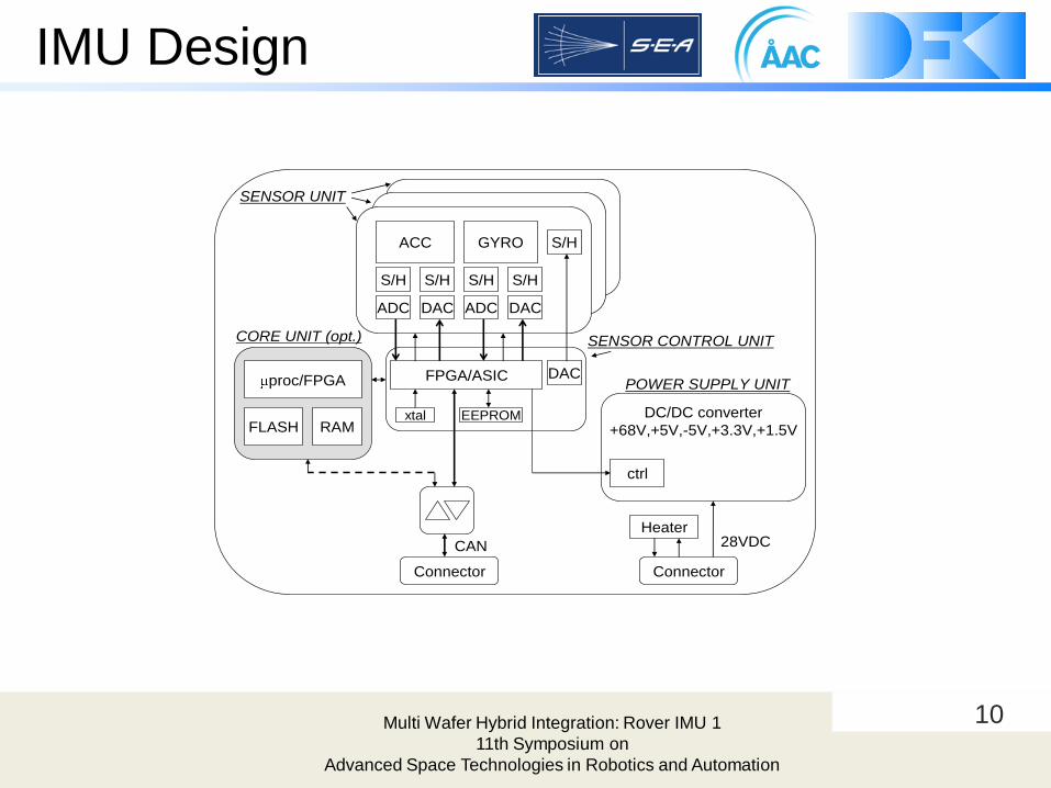
IMU Design
ACC GYRO
S/H S/H
ADC DAC
S/H S/H
ADC DAC
FPGA/ASIC
Heater
proc/FPGA
FLASH RAMxtal DC/DC converter
+68V,+5V,-5V,+3.3V,+1.5V
ctrl
Connector
28VDCCAN
SENSOR UNIT
CORE UNIT (opt.)
POWER SUPPLY UNIT
S/H
DAC
EEPROM
Connector
SENSOR CONTROL UNIT
Multi Wafer Hybrid Integration: Rover IMU 1
11th Symposium on
Advanced Space Technologies in Robotics and Automation

11
Alternatives
Alt. 1 Alt. 2 Alt. 3 Alt. 4
Estimated volume and
weight including
casing
1000cm3 / 450g 545cm3 / 245g 291cm3 / 185g 180cm3 / 143g
Power consumption
[AD5]
4,8W incl filter/
4,0W no filter
4,8W incl filter/
4,0W no filter
3,4W incl filter/
2,6W no filter
2,6W incl filter/
2,0W no filter
Required packaging
technology
development
None - Sensor front end
MCM (S/H)
- Sensor common
MCM
- FPGA and/or µ-
processor
interposer
- Mixed signal
ASIC on
interposer
- Sensor common
MCM
- FPGA and/or µ-
processor
interposer
- MCM with
FPGA/µ-controller,
RAM and flash
memory
- MCM including
mixed signal ASIC
and sensor
detectors as bare
die.
Critical components None - S/H as bare dies - Mixed-signal
ASIC
- Mixed-signal
ASIC
- Sensors as bare
dies.
Required new
component
development
None - If RTAX FPGA:
new interposer
design needed
- If RTAX FPGA:
new interposer
design needed
- If RTAX FPGA:
new interposer
design needed
Other needed
developmentPSU design PSU design PSU design PSU design
Critical items related
to packaging with
respect to the
environmental
requirements
None - BGA I/F (large
MCM)
- BGA I/F (high
density I/O MCM)
- Coating of MCM
- BGA I/F (high
density I/O MCM)
- Coating of MCM
- BGA I/F (large
MCM)
- BGA I/F (high
density I/O MCM)
- Coating of MCM
- Sensor mounting
as bare dies on
ceramic
substrates.
Multi Wafer Hybrid Integration: Rover IMU 1
11th Symposium on
Advanced Space Technologies in Robotics and Automation

12
Critical Items
• System Design
Accelerometer accuracy
PSU design
• Components
FPGA as bare die
Qualification of small passives
S/H availability as bare dies
• Miniaturization
BGA solder joint reliability
Sensor mounting and naked die preparation for flip-chip
Failure mechanism of internal routing cracking
Coating reliability
Break-Down voltage between BGA I/Os
Multi Wafer Hybrid Integration: Rover IMU 1
11th Symposium on
Advanced Space Technologies in Robotics and Automation

13
Miniaturisation
Test Samples
Multi Wafer Hybrid Integration: Rover IMU 1
11th Symposium on
Advanced Space Technologies in Robotics and Automation

14
Material Tests
• Tested: Si and LTCC interposers
• Vibration Test
• Shock Test 1500g
• Thermal cycling , survival
-135 to +85°C
• Life-time testing, Thermal cycling
operation -55 to +100°C
• Vacuum environment
• Inspection
• X-Ray
• Electrical
• Visual inspection of surface protection
Multi Wafer Hybrid Integration: Rover IMU 1
11th Symposium on
Advanced Space Technologies in Robotics and Automation

15
Material Test Results
• Vibration passed
• Shock passed
• Micro cracks due to too fast cooling after soldering and too high CTE (coefficient of thermal expansion)
• Thermal cycling (survival) partially compliant. Problem related to unsuitable underfill and soldering
• Thermal cycling (operational) partially compliant for SI interposers.
• Vacuum passed.
Micro cracks
LTCC
STABLCOR
Solder
sphere
LTCC
Carrier board
Cu/Ni/Au solder pad
Pb63Sn37
solder paste
Pb90Sn10 non-collapsing
solder sphere
Multi Wafer Hybrid Integration: Rover IMU 1
11th Symposium on
Advanced Space Technologies in Robotics and Automation

16Multi Wafer Hybrid Integration: Rover IMU 1
11th Symposium on
Advanced Space Technologies in Robotics and Automation
Hardware Concept
Breadboard

17
Breadboard Modules
Multi Wafer Hybrid Integration: Rover IMU 1
11th Symposium on
Advanced Space Technologies in Robotics and Automation
The IMU Breadboard Concept Design Integrates the
following Main modules:
► Existing Single axis SEA Gyro Module (consisting of a single AIS
Phase II Detector), Flight Experiment on Cryosat2
► Existing DFKI dual axis commercial Gyro module (consisting of
commercial gyro‟s and a commercial uP with an integrated software
Kalman Filter and a CAN interface).
► New triple axis commercial Accelerometer module (consisting of 3
single axis accelerometers, signal conditioning and an ADC)
„Towards a European MEMS Inertial Measurement Unit (IMU) Capability“ GNC 2011

18
Architecture
Multi Wafer Hybrid Integration: Rover IMU 1
11th Symposium on
Advanced Space Technologies in Robotics and Automation
IMU Breadboard Demonstrator Architectural Design

19Multi Wafer Hybrid Integration: Rover IMU 1
11th Symposium on
Advanced Space Technologies in Robotics and Automation
Integration of DFKI Module/ Accelerometer PCB/ Gyro into IMU Breadboard

20
IMU Breadboard
Multi Wafer Hybrid Integration: Rover IMU 1
11th Symposium on
Advanced Space Technologies in Robotics and Automation
Power Input
CAN Interface
CSI PCB
DFKI Module
(under)
FEE PCB
(under)
PSU PCB
(under)
Accelerometer
PCB
(under)
Mechanical
Base Plate

21
Gyro Calibration
Multi Wafer Hybrid Integration: Rover IMU 1
11th Symposium on
Advanced Space Technologies in Robotics and Automation
SEA Gyro Rate
Table & Controller
Rate Table Testing @
+/- 24 deg/sec

22
Gyro Error Plot
Multi Wafer Hybrid Integration: Rover IMU 1
11th Symposium on
Advanced Space Technologies in Robotics and Automation
Robotic IMU SEA Gyro Rate Error Plot
Dynamic Range
+/- 24 deg/sec
Scale Factor
0.015643
Scale Factor Error
<2000ppm
23Multi Wafer Hybrid Integration: Rover IMU 1
11th Symposium on
Advanced Space Technologies in Robotics and Automation
System Breadboard
Testing

24
Breadboard Testing
• Robotic Arm (DFKI)
Check the calibration
Determine the sensors capabilities for generic trajectories
• Rover Tests (DFKI, ESTEC)
Test the hardware for their targeted purpouse
Test in on target Platform
Multi Wafer Hybrid Integration: Rover IMU 1
11th Symposium on
Advanced Space Technologies in Robotics and Automation
25
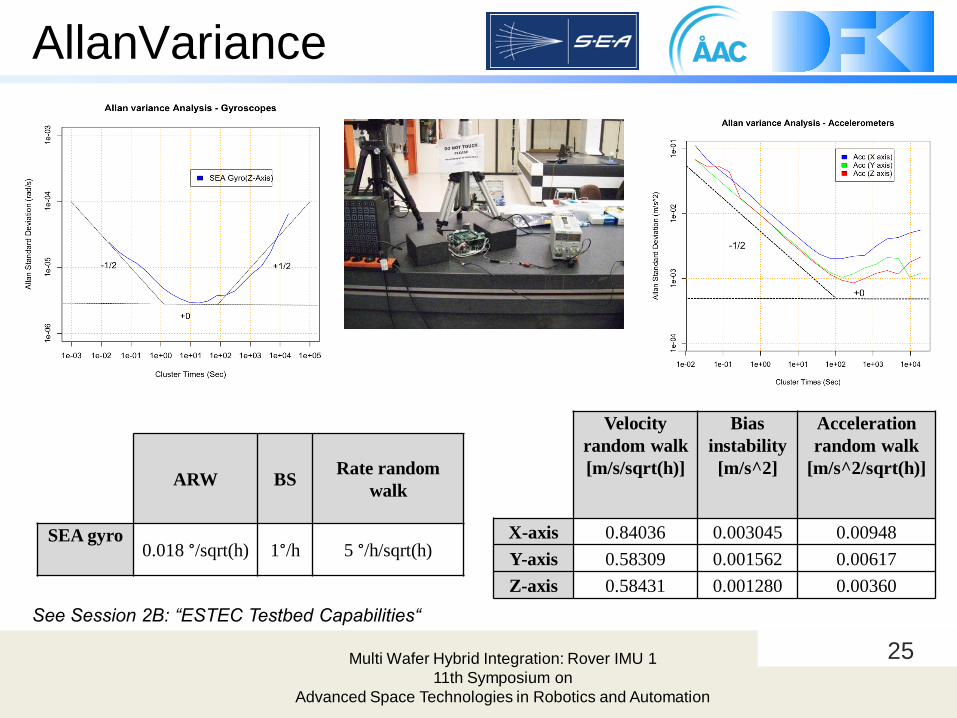
AllanVariance
Multi Wafer Hybrid Integration: Rover IMU 1
11th Symposium on
Advanced Space Technologies in Robotics and Automation
ARW BSRate random
walk
SEA gyro0.018 °/sqrt(h) 1°/h 5 °/h/sqrt(h)
Velocity
random walk
[m/s/sqrt(h)]
Bias
instability
[m/s^2]
Acceleration
random walk
[m/s^2/sqrt(h)]
X-axis 0.84036 0.003045 0.00948
Y-axis 0.58309 0.001562 0.00617
Z-axis 0.58431 0.001280 0.00360
See Session 2B: “ESTEC Testbed Capabilities“
26
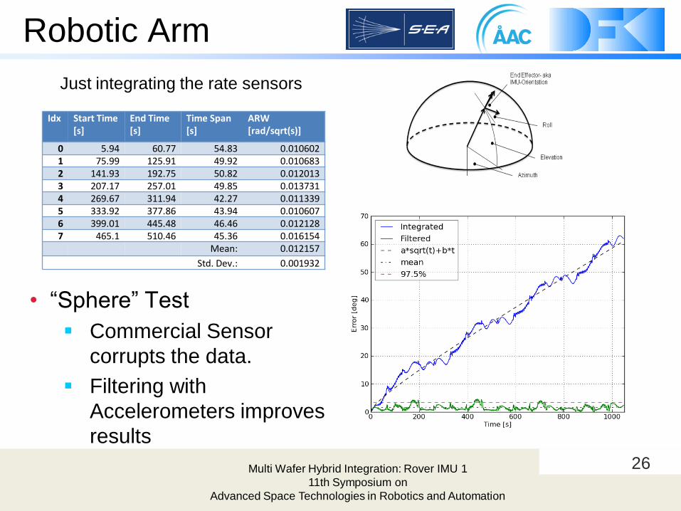
Robotic Arm
• “Sphere” Test
Commercial Sensor
corrupts the data.
Filtering with
Accelerometers improves
results
Multi Wafer Hybrid Integration: Rover IMU 1
11th Symposium on
Advanced Space Technologies in Robotics and Automation
Idx Start Time [s]
End Time [s]
Time Span [s]
ARW [rad/sqrt(s)]
0 5.94 60.77 54.83 0.0106021 75.99 125.91 49.92 0.0106832 141.93 192.75 50.82 0.0120133 207.17 257.01 49.85 0.0137314 269.67 311.94 42.27 0.0113395 333.92 377.86 43.94 0.0106076 399.01 445.48 46.46 0.0121287 465.1 510.46 45.36 0.016154
Mean: 0.012157
Std. Dev.: 0.001932
Just integrating the rate sensors
27
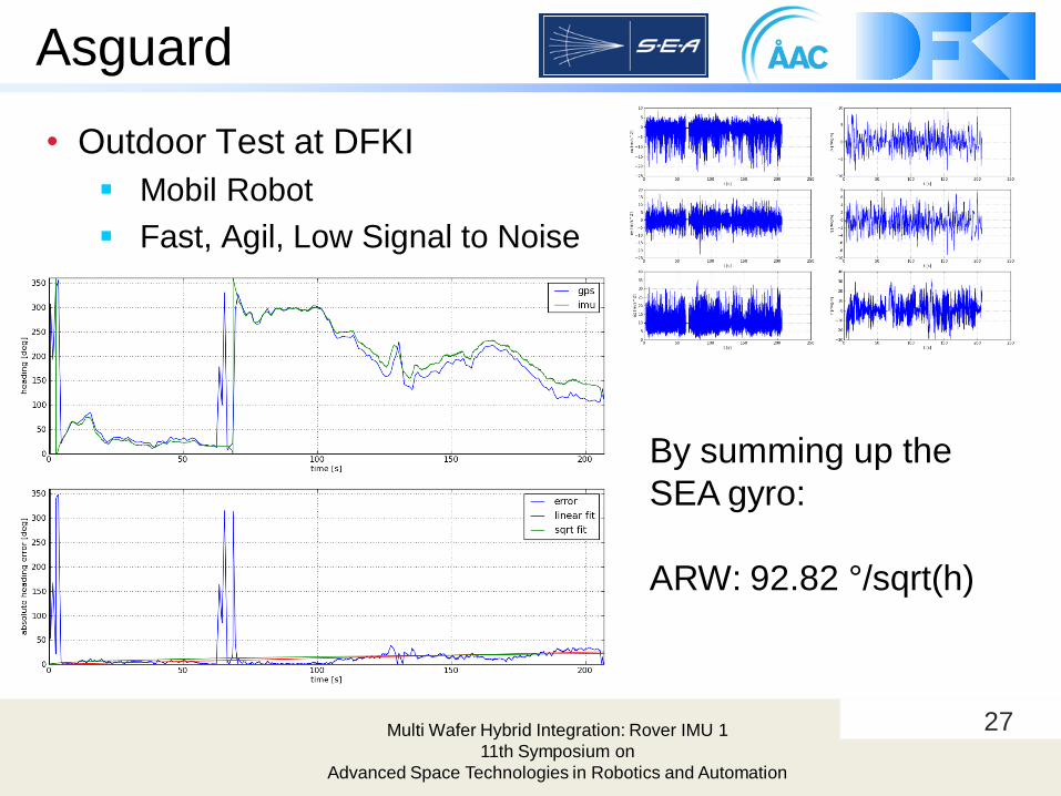
Asguard
Multi Wafer Hybrid Integration: Rover IMU 1
11th Symposium on
Advanced Space Technologies in Robotics and Automation
• Outdoor Test at DFKI
Mobil Robot
Fast, Agil, Low Signal to Noise
By summing up the
SEA gyro:
ARW: 92.82 °/sqrt(h)

28
ESTEC Rover
• At ESTEC Testbed
LRM Rover
Ackerman-Turn 2cm/s
• Results:
Square root fit (ARW):
0.83°/sqrt(h)
Linear fit (BS): 3.1°/h
Multi Wafer Hybrid Integration: Rover IMU 1
11th Symposium on
Advanced Space Technologies in Robotics and Automation

29Multi Wafer Hybrid Integration: Rover IMU 1
11th Symposium on
Advanced Space Technologies in Robotics and Automation
Conclusion
&
Future Work

30
Conclusion
• Miniaturisation is feasible and can be improve with better CTE match.
• The breadboard works reliable and delivers the required data.
• The commercial gyros introduce additional errors.
• The bias stability of the SEA gyro is within required limits.
• The angular random walk of the SEA gyro is within the required limits as a single sensor but could not be shown on the system due to errors added by the commercials sensors.
• The acceleration sensors are very close to the required limits, and have better properties than expected.
Presentation title
05/07/2006
Properties Best found Expected (Required)
Angular Random Walk 0.832 /sqrt(h) 0.5 /sqrt(h)
Gyro Bias Stability 3.1 /h 5.0 /h
Accelerometer Stability 9.84 millig 75 millig (1.2 millig)

31
Further work
• SEA Harmonised Gyro and equivalent accelerometers for
all three axes
• Modifying the MRS Gyro circuit design to suit maximum use
of bare die
• A new PSU to minimise both power loss and physical size
• Modification of the current FPGA code to allow „flash-
based‟ FPGAs as bare die to be used and also enable in-
flight re-programmability
• Refining the test, analysis and processing methods to
achieve the best possible accuracy
Multi Wafer Hybrid Integration: Rover IMU 1
11th Symposium on
Advanced Space Technologies in Robotics and Automation

32Multi Wafer Hybrid Integration: Rover IMU 1
11th Symposium on
Advanced Space Technologies in Robotics and Automation
Systems Engineering & Assessment
Aerospace Division
Bristol, England
www.sea.co.uk
DFKI Bremen
Robotics Innovations Center
www.dfki.de/robotics
Thank you for your attention!ǺAC Microtec
Uppsala Science Park
www.aacmicrotec.com