Á m/ ¨ i É i ° & $ $ - ° x % . - EASA | European Aviation Safety Agency · 2014-01-31 · 1...
95
-
Upload
phamnguyet -
Category
Documents
-
view
217 -
download
0
Transcript of Á m/ ¨ i É i ° & $ $ - ° x % . - EASA | European Aviation Safety Agency · 2014-01-31 · 1...
Project EASA.2008.C19
Burnthrough Resistance of Fuselage
easa.europa.eu

Disclaimer The information provided includes the personal views or recommendations of the respective authors, and does not necessarily reflect the views of EASA, or indicate a commitment to a particular course of action. The material is not a substitute for current legislative and regulatory provisions.
Ownership of all copyright and other intellectual property rights in this material including any documentation, data and technical information, remains vested to the European Aviation Safety Agency. Reproduction is authorized by express written permission from the European Aviation Safety Agency. The Agency shall always be acknowledged as the copyright owner of the information.
4207/R/000456/KK
BURNTHROUGH RESISTANCE OF FUSELAGE (EASA SERVICE CONTRACT NUMBER EASA 2008.C19)
Issue 5
Prepared for: European Aviation Safety Agency
July 2009
RGW CHERRY & ASSOCIATES LIMITED THE LORD WAKE SUITE
THE PRIORY, HIGH STREET, WARE, HERTFORDSHIRE
SG 12 9AL ENGLAND TEL: + (44) (0) 1920 466001 FAX: + (44) (0) 1920 466150
© Copyright 2009 RGW Cherry & Associates Limited. All rights reserved.
COMMERCIAL-IN-CONFIDENCE 4207/R/000456/KK
Issue 5 July 2009
RGW Cherry & Associates Limited Page 2 of 93
AMENDMENT RECORD
ISSUE NUMBER DATE REMARKS
1 December 2008 Initial Issue – Phase 1
2 March 2009 Phase 2
3 April 2009 Phase 3
4 June 2009 Final Report
5 July 2009 Minor correction to final report
COMMERCIAL-IN-CONFIDENCE 4207/R/000456/KK
Issue 5 July 2009
RGW Cherry & Associates Limited Page 3 of 93
CONTENTS
Executive Summary .................................................................................................7
Abbreviations ...........................................................................................................8
Definition of Terms...................................................................................................9
1 Introduction..................................................................................................10
2 Overview of Methodology...........................................................................11
2.1 Phase 1...............................................................................................11 2.2 Phase 2...............................................................................................12 2.3 Phase 3...............................................................................................12
3 Accident Analysis........................................................................................13
3.1 Relevant Accidents .............................................................................13 3.2 Overview of Accident Experience........................................................13
4 Burnthrough Related Issues ......................................................................14
4.1 Occupant Protection Time ..................................................................15 4.2 Fire Entry Paths ..................................................................................19
4.2.1 General Assessment................................................................19 4.2.2 Lower Fuselage Burnthrough...................................................23
4.2.2.1 Test & Accident Experience.......................................23 4.2.2.2 Fuselage Skin Abrasion.............................................24
4.2.3 Upper Fuselage Burnthrough...................................................25 4.2.3.1 Test & Accident Experience.......................................25 4.2.3.2 Fuselage Orientation .................................................33
4.2.4 Cabin Windows ........................................................................35 4.2.4.1 Test Evidence – Cabin Window Penetration .............35 4.2.4.2 Accident Evidence – Cabin Window Penetration.......37
4.2.5 Fire threats not mitigated by Enhanced Fuselage Burnthrough Protection.................................................................................40 4.2.5.1 Breaks and Ruptures .................................................40 4.2.5.2 Doors .........................................................................42 4.2.5.3 Overview....................................................................43
4.2.6 Installation of Thermal Acoustic Insulation...............................44 4.2.6.1 Attachment Means & Effects of Protective Treatments
...................................................................................44 4.2.6.2 Discontinuities............................................................45
4.2.7 Frame Collapse........................................................................46 4.2.8 Structural Integrity of Fuselage ................................................48
4.3 Advances in Technology .....................................................................50 4.3.1 Non-metallic Fuselages............................................................50
COMMERCIAL-IN-CONFIDENCE 4207/R/000456/KK
Issue 5 July 2009
RGW Cherry & Associates Limited Page 4 of 93
4.3.1.1 General ......................................................................50 4.3.1.2 Current Applications ..................................................50
4.3.2 External Fuselage Coatings .....................................................52 4.4 Summary of Conclusions ....................................................................53
5 Regulatory Options .....................................................................................55
5.1 Options to be considered ....................................................................56 5.2 Assessment of threat ..........................................................................58
6 Regulatory Impact Assessment .................................................................59
7 References ...................................................................................................60
Appendix 1 – Listing of Pertinent Burnthrough Related Literature ...................63
Appendix 2 – Analysis and Interpretation of FAA Test Results .........................83
COMMERCIAL-IN-CONFIDENCE 4207/R/000456/KK
Issue 5 July 2009
RGW Cherry & Associates Limited Page 5 of 93
FIGURES
Figure 1: Variation of Improvement in Fatality Rate with Additional Burnthrough Protection
Time for Aircraft with Metallic Fuselages Configured to Later Requirements............... 15
Figure 2: Evacuation and Burnthrough Time Sequence – Aircraft with Metallic Fuselages . 16
Figure 3: Cumulative Probability Distribution of Required Occupant Protection Time ......... 17
Figure 4: Typical Fire Paths into the Passenger Cabin ....................................................... 19
Figure 5 Potential Fire Entry Path through the Cargo Door into the Cheek ......................... 21
Figure 6: Burnthrough Accident: DC-9-32, Vigo, Spain, March 21st 1994 .......................... 29
Figure 7: Vigo DC 9-32 Skin Burnthrough of Lower and Upper Fuselage ........................... 30
Figure 8: Vigo DC 9-32 External Fire Damage Starboard Side ........................................... 31
Figure 9: Vigo DC 9-32 Minimal Fire Damage to Cabin Interior .......................................... 31
Figure 10: Vigo DC 9-32 Scorching Near Starboard Overwing Emergency Exit.................. 32
Figure 11: Vigo DC 9-32 Localized Fire Damage Due to Upper Fuselage Burnthrough...... 32
Figure 12: Proportion of Inverted Fuselages in Ground Pool Fire Accidents Not Involving
Fuselage Breaks ......................................................................................................... 33
Figure 13: Proportion of Pool Fire Accidents involving Fuselage Breaks............................. 41
Figure 14: Proportion of Pool Fire Accidents involving Fuselage Breaks or Ruptures ......... 41
Figure 15: Proportion of Pool Fire Accidents where an Open Door Contributed to Fire Entry
.................................................................................................................................... 42
Figure 16: Proportion of Pool Fire Accidents where Breaks, Ruptures, or an Open Door
Contributed to Fire Entry ............................................................................................. 43
Figure 17: Typical Installation of Foam Block Insulation System......................................... 46
Figure 18: FAA Kerosene Burner Test Frame Modified with Aluminium Frame and Stringers
.................................................................................................................................... 47
Figure 19: Photograph of Boeing 737 Accident – Manchester England 1985 showing
Structural Collapse...................................................................................................... 48
COMMERCIAL-IN-CONFIDENCE 4207/R/000456/KK
Issue 5 July 2009
RGW Cherry & Associates Limited Page 6 of 93
TABLES
Table 1: Lower Fuselage Burnthrough Details - FAA Full Scale Tests ................................ 23
Table 2: Upper Fuselage Burnthrough Details - FAA Full Scale Tests ................................ 26
Table 3: Upper Fuselage Burnthrough Times at Thermocouples (Location: Just Below
Windows) .................................................................................................................... 26
Table 4: Window Fire Penetration Times - FAA 1984 Tests................................................ 35
Table 5: Window Fire Penetration Details - FAA 1988/1989 Tests...................................... 36
COMMERCIAL-IN-CONFIDENCE 4207/R/000456/KK
Issue 5 July 2009
RGW Cherry & Associates Limited Page 7 of 93
EXECUTIVE SUMMARY
The European Aviation Safety Agency (EASA) amended CS-25, by the addition of 25.856(b), to require that Thermal Acoustic Insulation fitted to the lower half of the fuselage provides a fire barrier to protect the cabin from fire entry following a post impact pool fire. The aim of this study is to conduct an updated review of the potential risks posed to occupant survival from ground pool fires taking into account both aircraft design features and accident circumstances such as post-impact aircraft orientation, the presence of fuselage breaks, etc. This final report records the progress made in Phase 1, Phase 2, and Phase 3 of the study. It is concluded that a Burnthrough Protection Time of 5 minutes is likely to be adequate for the majority of pool fire threats. Conclusions have been made regarding burnthrough fire threats for the following subjects:
� Lower Fuselage � Upper Fuselage � Cargo Bays � Equipment Bays � Fuselage Inversion � Cabin Windows � Installation Issues � Aircraft Structural Integrity � Non-metallic Fuselages � Intumescent Coatings
Three Regulatory options were proposed and agreed with EASA based on the findings from Phase 2 of this study. During Phase 3 of this study, these options were subjected to a Regulatory Impact Assessment, which is contained in a stand-alone report. It concludes that CS 25.856(b) “Thermal /acoustic insulation materials” introduced by NPA 2008-13 should be deleted and replaced by a new objective rule. The new rule is likely to provide improved protection to occupants of aircraft, with metallic and non-metallic fuselages, at minimal cost increase.

COMMERCIAL-IN-CONFIDENCE 4207/R/000456/KK
Issue 5 July 2009
RGW Cherry & Associates Limited Page 8 of 93
ABBREVIATIONS
ADB CSRTG Accident Database AECMA European Association of Aerospace Industries AIA Aerospace Industries of America ATSB Australian Transport Safety Bureau CEAT Centre d'Essais Aeronautique de Toulouse CFRP Carbon Fibre Reinforced Polymer CIAIAC Civil Aviation Accident and Incident Investigation Commission - Spain CSRTG Cabin Safety Research Technical Group EASA European Aviation Safety Agency FAA Federal Aviation Administration NPA Notice of Proposed Amendment NPRM Notice of Proposed Rulemaking OPF Oxidized Polyacrylonitrile Fibre TAI Thermal Acoustic Insulation TC Transport Canada UK CAA United Kingdom Civil Aviation Authority
COMMERCIAL-IN-CONFIDENCE 4207/R/000456/KK
Issue 5 July 2009
RGW Cherry & Associates Limited Page 9 of 93
DEFINITION OF TERMS
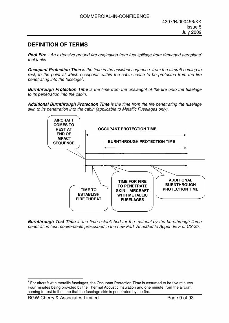
Pool Fire - An extensive ground fire originating from fuel spillage from damaged aeroplane’ fuel tanks Occupant Protection Time is the time in the accident sequence, from the aircraft coming to rest, to the point at which occupants within the cabin cease to be protected from the fire penetrating into the fuselage
1.
Burnthrough Protection Time is the time from the onslaught of the fire onto the fuselage to its penetration into the cabin. Additional Burnthrough Protection Time is the time from the fire penetrating the fuselage skin to its penetration into the cabin (applicable to Metallic Fuselages only). Burnthrough Test Time is the time established for the material by the burnthrough flame penetration test requirements prescribed in the new Part VII added to Appendix F of CS-25.
1 For aircraft with metallic fuselages, the Occupant Protection Time is assumed to be five minutes.
Four minutes being provided by the Thermal Acoustic Insulation and one minute from the aircraft coming to rest to the time that the fuselage skin is penetrated by the fire.
BURNTHROUGH PROTECTION TIME
AIRCRAFT COMES TO REST AT END OF IMPACT
SEQUENCE
TIME FOR FIRE TO PENETRATE
SKIN – AIRCRAFT WITH METALLIC
FUSELAGES
TIME TO ESTABLISH
FIRE THREAT
ADDITIONAL BURNTHROUGH
PROTECTION TIME
OCCUPANT PROTECTION TIME
COMMERCIAL-IN-CONFIDENCE 4207/R/000456/KK
Issue 5 July 2009
RGW Cherry & Associates Limited Page 10 of 93
1 INTRODUCTION
The European Aviation Safety Agency (EASA) amended CS-25, by the addition of 25.856(b), to require that Thermal Acoustic Insulation fitted to the lower half of the fuselage provides a fire barrier to protect the cabin from fire entry following a post impact pool fire. The use of Thermal Acoustic Insulation as a fire barrier does not provide complete protection and may not be the most cost beneficial means of achieving the safety intent. Furthermore, advances in technology (e.g. carbon composite fuselages) bring about further issues that may need to be addressed in regulating for enhanced burnthrough protection of aircraft. During the course of this study a complete review was carried out of the potential risks posed to occupant survival from ground pool fires taking into account both aircraft design features and accident circumstances (post-impact aircraft orientation, the presence of fuselage breaks, etc.). The study was divided into three phases: Phase 1 – Literature Search Phase 2 – Review & Analysis of Issues Phase 3 – Regulatory Impact Assessment This final report contains a description of the methodology and findings of this EASA study. A Regulatory Impact Assessment of the regulatory options agreed with EASA at the end of Phase 2 is contained in a stand-alone report.
COMMERCIAL-IN-CONFIDENCE 4207/R/000456/KK
Issue 5 July 2009
RGW Cherry & Associates Limited Page 11 of 93
2 OVERVIEW OF METHODOLOGY
2.1 PHASE 1
In Phase 1 of this study, a literature search was carried out to identify all relevant research papers, regulatory documents, and accident reports relating to fuselage burnthrough protection. The documents identified support the activities to be carried out in the later phases of this study. The primary sources used in the literature search were regulatory documents, supplied by EASA, FAA research and regulatory documents and research carried out by the UK CAA. Documents obtained in this manner referenced further documents that were acquired when considered pertinent to the study. A fundamental aspect of the study is the review of accident experience. The Cabin Safety Research Technical Group (CSRTG) Accident Database (Reference 1), supported by the in-house library of Accident Reports, was used as the primary means of identifying pool fire accidents. The criteria used for accident selection is contained in Section 3.1. The documents identified from the literature search and a listing of the burnthrough accidents identified is contained in Appendix 1, grouped into the following divisions:
� Burnthrough Research Papers � Materials – Research and Data � Manuals � Rulemaking Proposals (FAA NPRM and EASA NPA) � Comments on FAA NPRM � Comments on FAA Time Extension NPRM � Comments on EASA NPA � Final Rules � Ground Pool Fire Accidents � Miscellaneous
Relevant documents found subsequent to Phase 1 were progressively added to the Appendix 1 listing.
COMMERCIAL-IN-CONFIDENCE 4207/R/000456/KK
Issue 5 July 2009
RGW Cherry & Associates Limited Page 12 of 93
2.2 PHASE 2
In Phase 2 of this study, a review was carried out of research documents, regulatory documents, and in-service accident experience relating to fuselage burnthrough resulting from ground pool fires. The primary purpose of this review was to identify and evaluate fuselage burnthrough issues that could affect the level of protection from ground pool fires. The issues identified are as follows:
� Occupant Protection Time � Lower Fuselage Burnthrough � Upper Fuselage Burnthrough � Windows � Breaks, Ruptures and Doors � Cargo and Equipment Bays � Gaps and Clipping � Frame Collapse � Structural Integrity of Fuselage � Protective Coatings and Corrosion Inhibitors � Non-metallic Fuselages � Intumescent Paints
Full details of the methodology used for the identification and evaluation of these issues are described in Sections 4.1 to 4.3. These Sections also include a conclusion for each of the issues, which are summarised in Section 4.4.
2.3 PHASE 3
Phase 3 of this study involved an evaluation of the proposed regulatory options contained in Section 5 by means of a Regulatory Impact Assessment. The methodology used follows the guidelines contained in Reference 2.
COMMERCIAL-IN-CONFIDENCE 4207/R/000456/KK
Issue 5 July 2009
RGW Cherry & Associates Limited Page 13 of 93
3 ACCIDENT ANALYSIS
3.1 RELEVANT ACCIDENTS
The Accident Database (Reference 1) and in-house library of accident reports were used to identify ground pool fire accidents meeting the following criteria.
1. Western-built turbojet or turboprop aircraft 2. Passenger Operation (including passenger/cargo,
ferry/positioning or maintenance/check flight). 3. Certificated maximum passenger seating capacity of 20 or
greater 4. Accident date range 1966 to 2007 inclusive.
There were 367 fire related accidents in which the aircraft were destroyed, that met the above criteria. This is the number of accidents that potentially involved a ground pool fire, on the basis that a ground pool fire is likely to cause destruction of the aircraft. Accident Database full textual data was available (indicating availability of the accident report) for 187 of these accidents. The textual data was reviewed and 88 accidents were identified as involving a ground pool fire. These accidents are listed in Table A.1-9 of Appendix 1.
3.2 OVERVIEW OF ACCIDENT EXPERIENCE
Considerations regarding fuselage burnthrough protection gained prominence following the accident to the British Airtours Aircraft in Manchester, England on the 22
nd August 1985.
The subsequent accident investigation carried out by the UK Air Accidents Investigation Branch made the following Recommendation in their report (Reference 3) into the accident:
“The balance of effort in aircraft fire research should be restored by increased effort directed towards fire hardening of the hull, the limitation of fire transmission through the structure and the prevention of structural collapse in critical areas. Short term measures should be devised for application to existing types but, in the long term, fire criteria should form a part of international airworthiness requirements.”
COMMERCIAL-IN-CONFIDENCE 4207/R/000456/KK
Issue 5 July 2009
RGW Cherry & Associates Limited Page 14 of 93
4 BURNTHROUGH RELATED ISSUES
This Section of the report addresses those issues that are factors in the degree of protection afforded by enhanced burnthrough protection. The evaluation of these issues is based on both previous research and in-service accident experience supported in most instances by analysis carried out during the course of this study. A summary of the conclusions resulting from these evaluations is contained in Section 4.4
COMMERCIAL-IN-CONFIDENCE 4207/R/000456/KK
Issue 5 July 2009
RGW Cherry & Associates Limited Page 15 of 93
4.1 OCCUPANT PROTECTION TIME
The FAA Rule 25.856(b) is predicated on the assumption that an Additional Burnthrough Protection Time of four minutes is needed, for aircraft with metallic fuselages, to protect occupants from an intense pool fire. A study carried out for the UK CAA in 1998 (see Reference 4) into the likely benefit that might accrue from fire hardening of the entire fuselage, concluded that:
“The rate of improvement in benefit appears to vary exponentially with limited improvement beyond the four to eight minute additional protection point”.
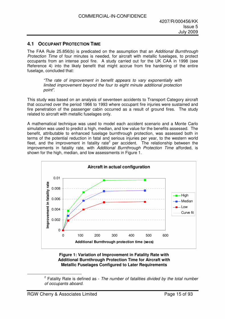
This study was based on an analysis of seventeen accidents to Transport Category aircraft that occurred over the period 1966 to 1993 where occupant fire injuries were sustained and fire penetration of the passenger cabin occurred as a result of ground fires. The study related to aircraft with metallic fuselages only. A mathematical technique was used to model each accident scenario and a Monte Carlo simulation was used to predict a high, median, and low value for the benefits assessed. The benefit, attributable to enhanced fuselage burnthrough protection, was assessed both in terms of the potential reduction in fatal and serious injuries per year, to the western world fleet, and the improvement in fatality rate
2 per accident. The relationship between the
improvements in fatality rate, with Additional Burnthrough Protection Time afforded, is shown for the high, median, and low assessments in Figure 1.
Aircraft in actual configuration
0
0.002
0.004
0.006
0.008
0.01
0 100 200 300 400 500 600
Additional Burnthrough protection time (secs)
Imp
rov
em
en
t in
fa
tali
ty r
ate
High
Median
Low
Curve fit
Figure 1: Variation of Improvement in Fatality Rate with Additional Burnthrough Protection Time for Aircraft with
Metallic Fuselages Configured to Later Requirements
2 Fatality Rate is defined as - The number of fatalities divided by the total number
of occupants aboard.
COMMERCIAL-IN-CONFIDENCE 4207/R/000456/KK
Issue 5 July 2009
RGW Cherry & Associates Limited Page 16 of 93
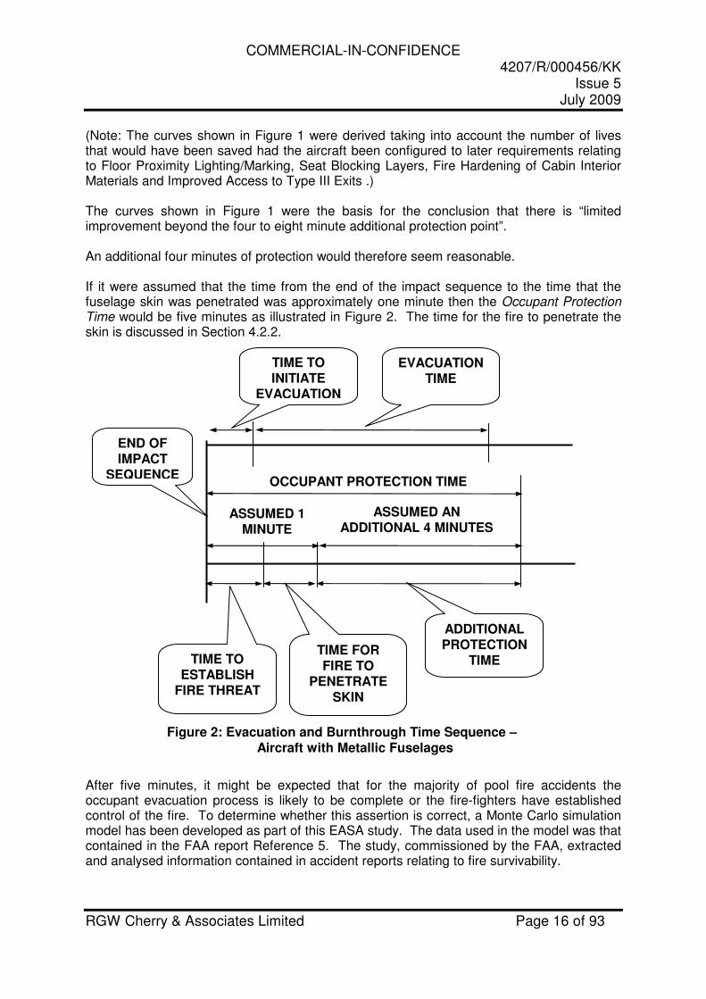
(Note: The curves shown in Figure 1 were derived taking into account the number of lives that would have been saved had the aircraft been configured to later requirements relating to Floor Proximity Lighting/Marking, Seat Blocking Layers, Fire Hardening of Cabin Interior Materials and Improved Access to Type III Exits .) The curves shown in Figure 1 were the basis for the conclusion that there is “limited improvement beyond the four to eight minute additional protection point”. An additional four minutes of protection would therefore seem reasonable. If it were assumed that the time from the end of the impact sequence to the time that the fuselage skin was penetrated was approximately one minute then the Occupant Protection Time would be five minutes as illustrated in Figure 2. The time for the fire to penetrate the skin is discussed in Section 4.2.2.
Figure 2: Evacuation and Burnthrough Time Sequence – Aircraft with Metallic Fuselages
After five minutes, it might be expected that for the majority of pool fire accidents the occupant evacuation process is likely to be complete or the fire-fighters have established control of the fire. To determine whether this assertion is correct, a Monte Carlo simulation model has been developed as part of this EASA study. The data used in the model was that contained in the FAA report Reference 5. The study, commissioned by the FAA, extracted and analysed information contained in accident reports relating to fire survivability.
ASSUMED 1 MINUTE
END OF IMPACT
SEQUENCE
EVACUATION TIME
TIME FOR FIRE TO
PENETRATE SKIN
TIME TO ESTABLISH
FIRE THREAT
ADDITIONAL PROTECTION
TIME
ASSUMED AN ADDITIONAL 4 MINUTES
TIME TO INITIATE
EVACUATION
OCCUPANT PROTECTION TIME
COMMERCIAL-IN-CONFIDENCE 4207/R/000456/KK
Issue 5 July 2009
RGW Cherry & Associates Limited Page 17 of 93
0.00
0.10
0.20
0.30
0.40
0.50
0.60
0.70
0.80
0.90
1.00
0 60 120 180 240 300 360 420 480 540 600
TIME (Seconds)4 2 0 7 / Su p p o r t I n f o r ma t i o n / E v a c u a t i o n & F i r e f i g h t e r s M o d e l
CU
MU
LA
TIV
E P
RO
BA
BIL
ITY
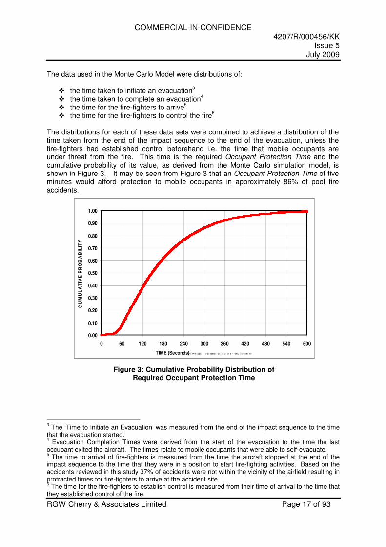
The data used in the Monte Carlo Model were distributions of:
� the time taken to initiate an evacuation3
� the time taken to complete an evacuation4
� the time for the fire-fighters to arrive5
� the time for the fire-fighters to control the fire6
The distributions for each of these data sets were combined to achieve a distribution of the time taken from the end of the impact sequence to the end of the evacuation, unless the fire-fighters had established control beforehand i.e. the time that mobile occupants are under threat from the fire. This time is the required Occupant Protection Time and the cumulative probability of its value, as derived from the Monte Carlo simulation model, is shown in Figure 3. It may be seen from Figure 3 that an Occupant Protection Time of five minutes would afford protection to mobile occupants in approximately 86% of pool fire accidents.
Figure 3: Cumulative Probability Distribution of Required Occupant Protection Time
3 The ‘Time to Initiate an Evacuation’ was measured from the end of the impact sequence to the time
that the evacuation started. 4 Evacuation Completion Times were derived from the start of the evacuation to the time the last
occupant exited the aircraft. The times relate to mobile occupants that were able to self-evacuate. 5 The time to arrival of fire-fighters is measured from the time the aircraft stopped at the end of the
impact sequence to the time that they were in a position to start fire-fighting activities. Based on the accidents reviewed in this study 37% of accidents were not within the vicinity of the airfield resulting in protracted times for fire-fighters to arrive at the accident site. 6 The time for the fire-fighters to establish control is measured from their time of arrival to the time that
they established control of the fire.
COMMERCIAL-IN-CONFIDENCE 4207/R/000456/KK
Issue 5 July 2009
RGW Cherry & Associates Limited Page 18 of 93
Whilst the number of occupants still to evacuate the aircraft after 5 minutes is unknown, it is unlikely that fuselage protection beyond this time would be cost beneficial. If it were assumed that the time, from the end of the impact sequence to the time that the pool fire penetrates the metallic skin of the aircraft, is approximately one minute (see Section 4.2.2) then the additional burnthrough protection time needed would be four minutes.
Conclusion 1: On the assumption that an average time for establishing the fire threat and penetrating the skin of a metallic aircraft is approximately one minute, an additional burnthrough protection time of 4 minutes is likely to provide adequate occupant protection for the majority of pool fire threats.
COMMERCIAL-IN-CONFIDENCE 4207/R/000456/KK
Issue 5 July 2009
RGW Cherry & Associates Limited Page 19 of 93
4.2 FIRE ENTRY PATHS
4.2.1 General Assessment
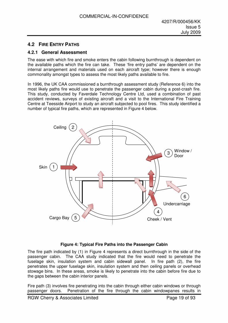
The ease with which fire and smoke enters the cabin following burnthrough is dependent on the available paths which the fire can take. These ‘fire entry paths’ are dependent on the internal arrangement and materials used on each aircraft type; however there is enough commonality amongst types to assess the most likely paths available to fire. In 1996, the UK CAA commissioned a burnthrough assessment study (Reference 6) into the most likely paths fire would use to penetrate the passenger cabin during a post-crash fire. This study, conducted by Faverdale Technology Centre Ltd, used a combination of past accident reviews, surveys of existing aircraft and a visit to the International Fire Training Centre at Teesside Airport to study an aircraft subjected to pool fires. This study identified a number of typical fire paths, which are represented in Figure 4 below.
Figure 4: Typical Fire Paths into the Passenger Cabin
The fire path indicated by (1) in Figure 4 represents a direct burnthrough in the side of the passenger cabin. The CAA study indicated that the fire would need to penetrate the fuselage skin, insulation system and cabin sidewall panel. In fire path (2), the fire penetrates the upper fuselage skin, insulation system and then ceiling panels or overhead stowage bins. In these areas, smoke is likely to penetrate into the cabin before fire due to the gaps between the cabin interior panels.
Fire path (3) involves fire penetrating into the cabin through either cabin windows or through passenger doors. Penetration of the fire through the cabin windowpanes results in
1
3
2
5
4
6
Skin
Ceiling
Window / Door
Cheek / Vent Cargo Bay
Undercarriage
COMMERCIAL-IN-CONFIDENCE 4207/R/000456/KK
Issue 5 July 2009
RGW Cherry & Associates Limited Page 20 of 93
immediate access to occupied areas (in contrast with the fuselage skin where the fire has also to penetrate the insulation system and interior panels). Window seals may also emit smoke when exposed to fire. The study also identified the cabin doors as possible fire paths. The report states that the fuselage door should be capable of offering at least as much protection as the fuselage; consisting of skin, insulation system and some form of substantial interior panel. The seals around doors also present a possible fire entry route if the materials used for the seals are not fire resistant. Fire paths through the lower fuselage (4) include burnthrough of the fuselage skin and then the insulation bags into the cheek area. The cheek area can often span a significant length of the fuselage (normally only stopped by wing box/main landing gear stowage), allowing fire to spread down the length of the fuselage and follow any path available into the passenger cabin. Once in the cheek area, the primary paths for fire to enter the cabin are either through the main cargo compartment or through the return air grills in the dado panel. For new Part 25 aircraft carrying passengers only, a class C compartment (see CS 25.857) would be used for the main cargo compartment, which consists of sidewall and ceiling cargo liners tested to CS-25 Annex F Part III (see CS 25.855). This presents a significant fire barrier and therefore the immediate threat to the cabin will be through the return air grills. Fire path (5) through the lower fuselage into the cargo compartment would require penetration of the fuselage skin, insulation bags and then the cargo compartment floor and liner. Unlike the sidewall and ceiling liners, the floor liner of a class C cargo compartment needs only meet the less stringent CS-25 Annex F Part I test, however the fire would still need to penetrate the ceiling liner, cabin floor and its covering before entering the passenger compartment. Additionally, full-scale fire testing conducted by the FAA (Reference 7) indicated that the aircraft is less vulnerable to path (5) when the gear is collapsed; however, the exposed cheek area (path 4) is a likely area for flame penetration with gear in either position. The final fire path (6) identified in the CAA study was through the main landing gear bay. With the landing gear extended, fire may enter the bay and have direct access to the pressure floor. To enter the cabin, the fire would need to burnthrough the pressure floor, insulation system and then cabin floor. The extent of opening into the landing gear bay is dependent on the aircraft design; some aircraft may have the doors open and others may be partially or fully closed when the landing gear is extended. A similar situation would exist for the nose gear bay.
COMMERCIAL-IN-CONFIDENCE 4207/R/000456/KK
Issue 5 July 2009
RGW Cherry & Associates Limited Page 21 of 93
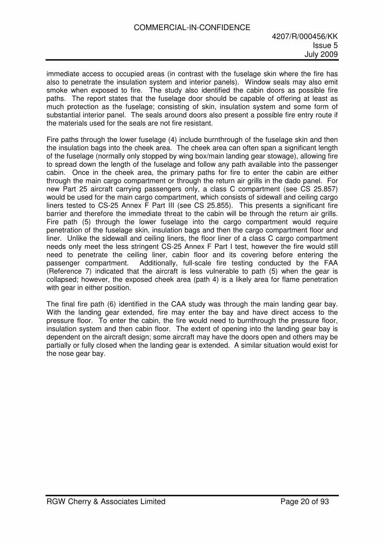
An additional fire path (7) in the lower fuselage relates to the cargo compartment door, as illustrated in Figure 5.
Figure 5 Potential Fire Entry Path through the Cargo Door into the Cheek
If fire burns through the cargo door skin, it can either penetrate the interior skin of the door and enter the cargo compartment, or penetrate the door sidewall or top panel and enter the cheek area. Fire entering the cargo compartment is covered by fire path (5), however, if the cargo access door does not have a cargo liner tested to Appendix F Part III, fire could enter the cheek area. To prevent the fire entering the cheek area through the cargo access door, it must be ensured that either the door itself, or the sidewall and top panel around the door are protected from burnthrough. A similar situation also exists for other access doors in the lower fuselage, such as for equipment bays. In summary, the fire path of least resistance to the passenger cabin from the upper fuselage is likely to be through the skin (path 1) or a cabin window (path 3). Through the lower fuselage, burnthrough into the cheek area can provide direct entry into the passenger cabin through the return air grills. These are indicated in Figure 4 by the darker arrows. When considering the entire aircraft length, there are additional lower fuselage fire paths in areas without the cargo compartment, which would present a similar fire path as the cheek areas. The FAA testing (Reference 7) indicated that the aircraft is more vulnerable with the gear extended, due to the larger surface area exposed to the fire. This configuration exposes additional paths through the main and nose landing gear bays that may be open.
7
Cargo Compartment Cheek
Area
COMMERCIAL-IN-CONFIDENCE 4207/R/000456/KK
Issue 5 July 2009
RGW Cherry & Associates Limited Page 22 of 93
Additionally, the empennage crawlthrough is generally only partially insulated and can provide a direct path through the skin. Experience indicates that a fire with the ferocity of a typical ground pool fire will use any path available to it to penetrate the structure. While CS 25.856(b) provides improved protection for the lower fuselage where insulation is present, it provides no improvement to the situation in the upper fuselage. Where gaps are present in the lower fuselage insulation system, fire may penetrate into the aircraft. The most likely fire paths described above for the lower fuselage indicate that protection of the cheek area should be paramount. By ensuring no gaps are present in the insulation system for the cheek area, and protecting against fire entering the cheek area from under the cargo compartment, this may improve the overall fire resistance of the lower fuselage. While this review indicates the quickest fire paths likely to be present in an aircraft subjected to a ground pool fire, it does not assess the relative fire / smoke threat posed by each path.
Conclusion 2: There are many potential fire paths that exist through to the cabin from a pool fire. It is likely that the quickest fire paths present in an aircraft subjected to a ground pool fire are the cheek area in the lower fuselage, the upper fuselage skin, and windows. However, no conclusions can be reached regarding the relative threat posed by each of the potential fire paths.
COMMERCIAL-IN-CONFIDENCE 4207/R/000456/KK
Issue 5 July 2009
RGW Cherry & Associates Limited Page 23 of 93
4.2.2 Lower Fuselage Burnthrough
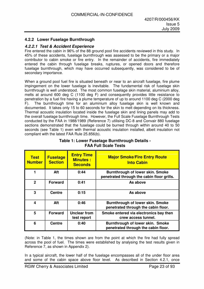
4.2.2.1 Test & Accident Experience Fire entered the cabin in 96% of the 88 ground pool fire accidents reviewed in this study. In 45% of these accidents, fuselage burnthrough was assessed to be the primary or a major contributor to cabin smoke or fire entry. In the remainder of accidents, fire immediately entered the cabin through fuselage breaks, ruptures, or opened doors and therefore fuselage burnthrough, which may have occurred subsequently, was considered to be of secondary importance. When a ground pool fuel fire is situated beneath or near to an aircraft fuselage, fire plume impingement on the lower fuselage is inevitable. The fundamental risk of fuselage skin burnthrough is well understood. The most common fuselage skin material, aluminium alloy, melts at around 600 deg C (1100 deg F) and consequently provides little resistance to penetration by a fuel fire having a plume temperature of up to around 1100 deg C (2000 deg F). The burnthrough time for an aluminium alloy fuselage skin is well known and documented. It takes only 15 to 60 seconds for the skin to melt depending on its thickness. Thermal acoustic insulation located inside the fuselage skin and lining panels may add to the overall fuselage burnthrough time. However, the Full Scale Fuselage Burnthrough Tests conducted by the FAA in 1988/1989 (Reference 7) utilising DC-8 and Convair 880 fuselage sections demonstrated that the fuselage could be burned through within around 40 to 50 seconds (see Table 1) even with thermal acoustic insulation installed, albeit insulation not compliant with the latest FAA Rule 25.856(b).
Table 1: Lower Fuselage Burnthrough Details - FAA Full Scale Tests
Test Number
Fuselage Section
Entry Time Minutes : Seconds
Major Smoke/Fire Entry Route
Into Cabin
1 Aft 0:44 Burnthrough of lower skin. Smoke penetrated through the cabin floor grills.
2 Forward 0:41 As above
3 Centre 0:15 As above
4 Aft 0:46 Burnthrough of lower skin. Smoke penetrated through the cabin floor.
5 Forward Unclear from test report
Smoke entered via electronics bay then crew access tunnel.
6 Centre 0:40 Burnthrough of lower skin. Smoke penetrated through the cabin floor.
(Note: in Table 1, the times shown are from the point at which the fire had fully spread across the pool of fuel. The times were established by analysing the test results given in Reference 7, as shown in Appendix 2). In a typical aircraft, the lower half of the fuselage encompasses all of the under floor area and some of the cabin space above floor level. As described in Section 4.2.1, once

COMMERCIAL-IN-CONFIDENCE 4207/R/000456/KK
Issue 5 July 2009
RGW Cherry & Associates Limited Page 24 of 93
burnthrough of the lower fuselage skin has occurred in the cheek area below floor level, fire or smoke is able to enter the occupied cabin relatively unrestricted via the air return grills. This would present an immediate threat to the survivability of evacuating occupants. This is supported by evidence from the FAA 1988/1989 tests (see Table 1) and a number of accident reports. In contrast, burnthrough of the fuselage skin above the floor level may present a lower risk if the cabin lining panels are capable of providing additional protection. This would be dependent on their fire resistance properties and whether joints between the panels are capable of resisting the passage of smoke and fire. Unless the lining panels and their installation were specifically designed to resist fire penetration it is most unlikely that they would offer any significant protection. Rapid smoke entry via the avionics bay was reported during one of the FAA 1988/1989 full scale tests and the bay was described as un-insulated. Avionics and other heat generating bays requiring the dissipation of heat may logically have no insulation on the inside of the fuselage skin. Clearly un-insulated areas such as these, where the only fire barrier is the fuselage skin, are extremely vulnerable to rapid burnthrough. Extremely rapid smoke entry past door seals occurred during some of the FAA 1988/1989 full scale tests, although the quantity of smoke was relatively small and the risk was minimal compared with the major entry routes. Smoke entry past door seals could occur where small gaps between the door seal and the surround exist or because the seal is damaged by the fire. Seal material could be optimized to maximize burn resistance. In most aircraft, the cabin windows are located in the upper half of the fuselage. However, in some aircraft the cabin windows may be located, or partially located, in the lower half. The fire penetration risks presented by cabin windows have been assessed separately in Section 4.2.4.
4.2.2.2 Fuselage Skin Abrasion Many ground pool fire accidents involve a ground slide with the landing gear separated from the aircraft or with the landing gear retracted. In these accidents, it is very likely that the underside of the fuselage will suffer significant abrasion, particularly if the ground slide occurs on a hard surface such as runway paving. This is significant, because fuselages could potentially be protected against burnthrough by the application of an external fire resistant layer e.g. intumescent paint. Clearly, external fire protection could be damaged during an accident impact sequence rendering it ineffective.
Conclusion 3: Lower skin burnthrough is possible in 15 – 60 seconds, depending on skin thickness. Air return grills, if present, provide an easy path for smoke and fire to penetrate the cabin following burnthrough of the lower skin.
Conclusion 4: In areas of the fuselage having a cargo bay, the presence of liners will still allow fire to reach the air return grills, but may prevent the fire from accessing the cabin floor.
Conclusion 5: Equipment bays might have un-insulated fuselage skin, and if so, would not benefit from the additional fire penetration resistance afforded by insulation. Fire burnthrough into equipment bays gives the fire direct access to the fuselage floor or air return grills.
COMMERCIAL-IN-CONFIDENCE 4207/R/000456/KK
Issue 5 July 2009
RGW Cherry & Associates Limited Page 25 of 93
4.2.3 Upper Fuselage Burnthrough
4.2.3.1 Test & Accident Experience With the aircraft in its normal orientation, either on or off its undercarriage, there is little doubt as to the risk posed to the lower fuselage from the ground fire plume. The CS 25.856(b) rule, employing thermal acoustic insulation as a flame penetration barrier within the lower half of the fuselage, aims to address this risk. However, the risk to the upper fuselage is less clear. CS 25.856(b) does not require protection for the upper fuselage. It would be reasonable to assume that the upper fuselage is shielded to some degree against a ground fire by the lower fuselage and therefore may be at less risk of burnthrough. Nevertheless, on some occasions the fire plume may present a significant risk to the upper fuselage, including instances when it is blown against the upper fuselage by wind. However, in this situation the heat flux may be significantly different from that normally experienced by the lower fuselage. Additionally, the risk of burnthrough to the upper fuselage is increased if the fuselage becomes inverted during the accident. In this situation, the burnthrough risk to the upper skin would be similar to the risk normally posed to the lower skin. The study has therefore utilised accident evidence to establish the prevalence of inverted, or adversely orientated, fuselages in ground fire accidents. In order to evaluate the burnthrough risk to the upper fuselage, evidence has been sought from full-scale fuselage tests and accident data.
4.2.3.1.1 Evidence from Full Scale Fuselage Tests The FAA carried out 6 full-scale fuselage burnthrough tests during 1988 and 1989 (Reference 7) utilising large burning kerosene pools located at ground level. These tests are extremely important within the context of this study because the pool fires were extinguished before the fuselage had completely burned out, preserving vital data on the extent of skin burnthrough. This information is seldom preserved in most real pool fire accidents. All six tests were conducted with the fuselage in the normal orientation. Tests 1, 2, and 3 had the landing gear retracted with the fuselage resting on its belly and Tests 4, 5 and 6 had the fuselage supported on its landing gear. A detailed examination of the test records given in Reference 7 was carried out to determine the likelihood of upper fuselage burnthrough and where possible determine upper fuselage burnthrough times. Two sources of data were available within Reference 7 as follows:- Firstly, the narrative provided an account of the fire damage suffered by the fuselage and the fire duration for each test. This provided times within which burnthrough of the upper half of the fuselage had occurred, but not the absolute minimum burnthrough times. Secondly, thermocouples located on the test fuselages were used to monitor the skin temperatures. These enabled burnthrough times at these locations to be determined.
COMMERCIAL-IN-CONFIDENCE 4207/R/000456/KK
Issue 5 July 2009
RGW Cherry & Associates Limited Page 26 of 93
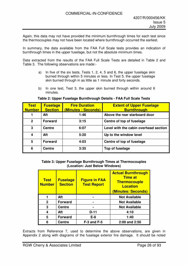
Again, this data may not have provided the minimum burnthrough times for each test since the thermocouples may not have been located where burnthrough occurred the earliest. In summary, the data available from the FAA Full Scale tests provides an indication of burnthrough times in the upper fuselage, but not the absolute minimum times. Data extracted from the results of the FAA Full Scale Tests are detailed in Table 2 and Table 3. The following observations are made:-
a) In five of the six tests, Tests 1, 2, 4, 5 and 6, the upper fuselage skin burned through within 5 minutes or less. In Test 5, the upper fuselage skin burned through in as little as 1 minute and forty seconds.
b) In one test, Test 3, the upper skin burned through within around 6
minutes.
Table 2: Upper Fuselage Burnthrough Details - FAA Full Scale Tests
Test Number
Fuselage Section
Fire Duration (Minutes : Seconds)
Extent of Upper Fuselage Burnthrough
1 Aft 1:46 Above the rear starboard door
2 Forward 3:15 Centre of top of fuselage
3 Centre 6:07 Level with the cabin overhead section
4 Aft 5:20 Up to the window level
5 Forward 4:03 Centre of top of fuselage
6 Centre 3:35 Top of fuselage
Table 3: Upper Fuselage Burnthrough Times at Thermocouples (Location: Just Below Windows)
Test Number
Fuselage Section
Figure in FAA Test Report
Actual Burnthrough Time at
Thermocouple Location
(Minutes: Seconds)
1 Aft - Not Available
2 Forward - Not Available
3 Centre - Not Available
4 Aft D-11 4:10
5 Forward E-8 1:40
6 Centre F-3 and F-5 2:00 and 2:50
Extracts from Reference 7, used to determine the above observations, are given in Appendix 2 along with diagrams of the fuselage exterior fire damage. It should be noted
COMMERCIAL-IN-CONFIDENCE 4207/R/000456/KK
Issue 5 July 2009
RGW Cherry & Associates Limited Page 27 of 93
that all times given above are from the time the fire had spread fully across the surface of the fuel pool. The fact that in five out of six full-scale tests skin burnthrough occurred in the upper half of the fuselage within five minutes, clearly demonstrates the vulnerability of the upper fuselage skin to burnthrough. However, it is evident from the test results, as demonstrated in the damage diagrams shown in Appendix 2, that upper fuselage burnthrough may not be as extensive or severe as in the lower fuselage. Nonetheless, burnthrough did occur during these fully representative tests and even a small area of burnthrough might allow sufficient smoke or fire to enter the cabin and impede evacuation. This evidence from the FAA full scale fuselage burnthrough tests suggests that protection of only the lower half of the fuselage, as required by CS 25.856(b), may not provide the level of flame penetration resistance and improvement to occupant survivability intended. Additional evidence was sought from actual aircraft accidents.
COMMERCIAL-IN-CONFIDENCE 4207/R/000456/KK
Issue 5 July 2009
RGW Cherry & Associates Limited Page 28 of 93
4.2.3.1.2 Evidence from Aircraft Accidents
Obtaining detailed and good quality evidence of upper fuselage skin burnthrough from aircraft accident data proved very difficult in this study. Invariably, once a fire has penetrated the cabin from outside, an extensive fire takes hold within the cabin, which then burns through the upper fuselage from inside. This destroys any physical evidence of burnthrough of the upper fuselage caused by the external fire. Witness accounts of upper fuselage burnthrough were non-existent, since despite observing smoke entry into the cabin the occupants clearly had no visibility of the precise entry point through the fuselage skin, as it would be obscured by the cabin floor, sidewall and ceiling panels. Furthermore, any persons located outside the aircraft would have their view restricted by flames and smoke. Only where there were obvious fire entry points did the occupants recall detailed information, for example when the fire entered an opened cabin door, window or break in the fuselage. Of all the 88 burnthrough accidents, reviewed in this study, adequate information on burnthrough damage to the upper fuselage was available in only one. This was the only accident where the fire was extinguished sufficiently quickly to preserve the external fire damage. In addition, the time taken to extinguish the fire was recorded and excellent photographic records were available showing the extent of exterior damage and the fire entry position through the cabin interior panels. This accident occurred in 1994 to a DC-9 aircraft at Vigo Airport in Spain.
COMMERCIAL-IN-CONFIDENCE 4207/R/000456/KK
Issue 5 July 2009
RGW Cherry & Associates Limited Page 29 of 93
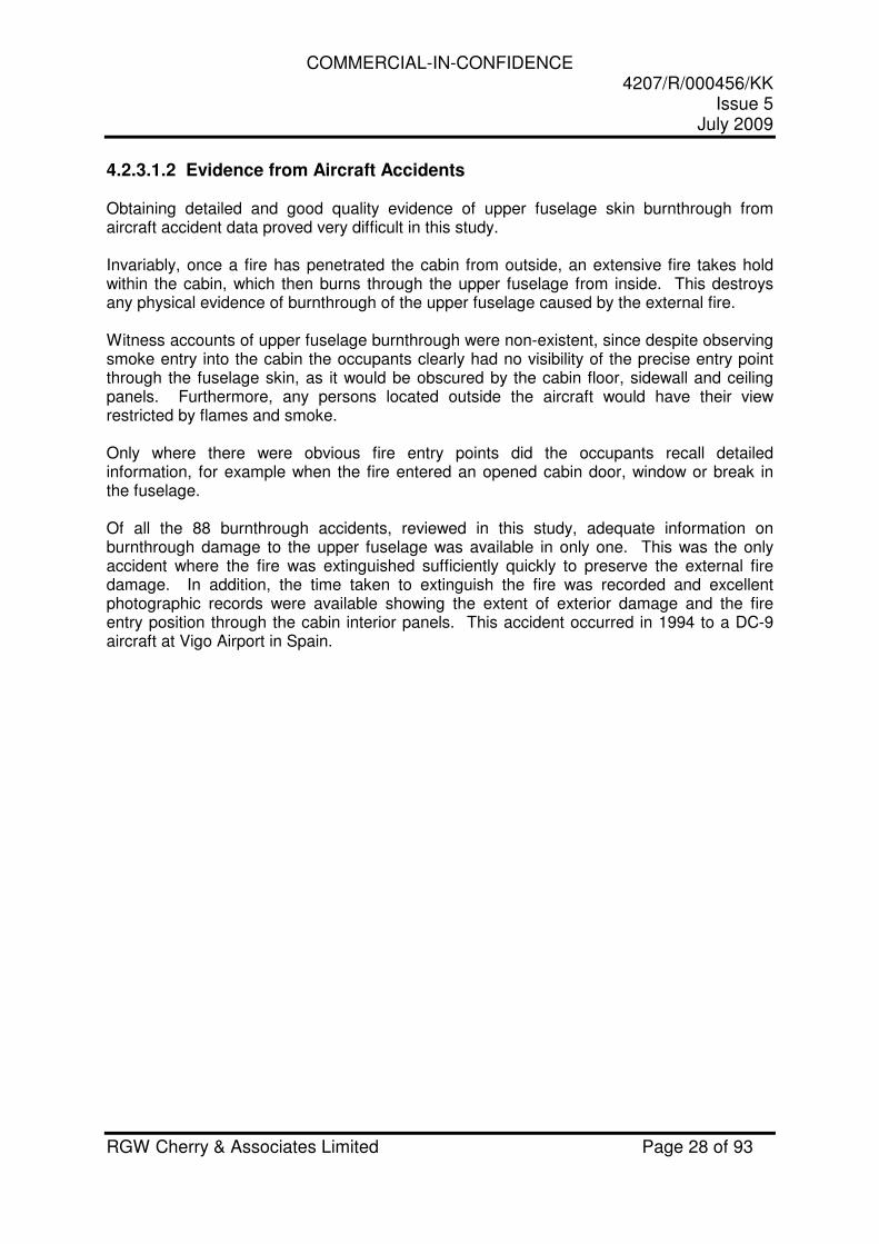
Burnthrough Accident: DC-9-32, Vigo, Spain, March 21st 1994
A resume of the accident is as follows. This is extracted from a translation of the accident report (Reference 8):-
This accident occurred at Vigo Airport, Spain on March 21st 1994 and involved a McDonnell Douglas DC 9-32 aircraft. The aircraft was too low on approach. The main undercarriage contacted approach lights and upward sloping ground just ahead of the runway, detaching the main undercarriage legs and part of the right hand wing fuel tank. Leaking fuel ignited and the fire followed the aircraft to where it stopped just to the side of the runway. When the aircraft stopped, the fire passed to the left side and affected practically the whole of the exterior of the plane, causing heavy damage.
Figure 6: Burnthrough Accident: DC-9-32, Vigo, Spain, March 21st 1994
When the aircraft entered the runway, a nearby vehicle notified an emergency on frequency 121.5 MHz. Immediately the Control Tower alerted the Fire Service which left with all its appliances. Approximately one minute after the alarm was raised the Fire Service appliances arrived at the aircraft and began to work on the left wing to protect the evacuation. 30 seconds later, the fire on that side was extinguished and they moved to work on the right wing, with the fire being extinguished one minute later.
No sooner had the aircraft stopped; the crew ordered and directed its evacuation, as well as distancing the passengers from the area affected by the fire. The evacuation passed off in an orderly manner.
COMMERCIAL-IN-CONFIDENCE 4207/R/000456/KK
Issue 5 July 2009
RGW Cherry & Associates Limited Page 30 of 93
In the evacuation the two front doors and the two emergency exits located over the left wing were used. The forward overwing emergency exit was opened and on causing smoke to enter the cabin an unsuccessful attempt was made to close it.
Once the fire was extinguished, barely two minutes after their arrival at the aircraft, some members of the Fire Service equipped with oxygen cylinders and mask entered the aircraft’s cabin, checking that it had been totally evacuated.
Of the 110 passengers and 6 crew, all evacuated with no fatalities.
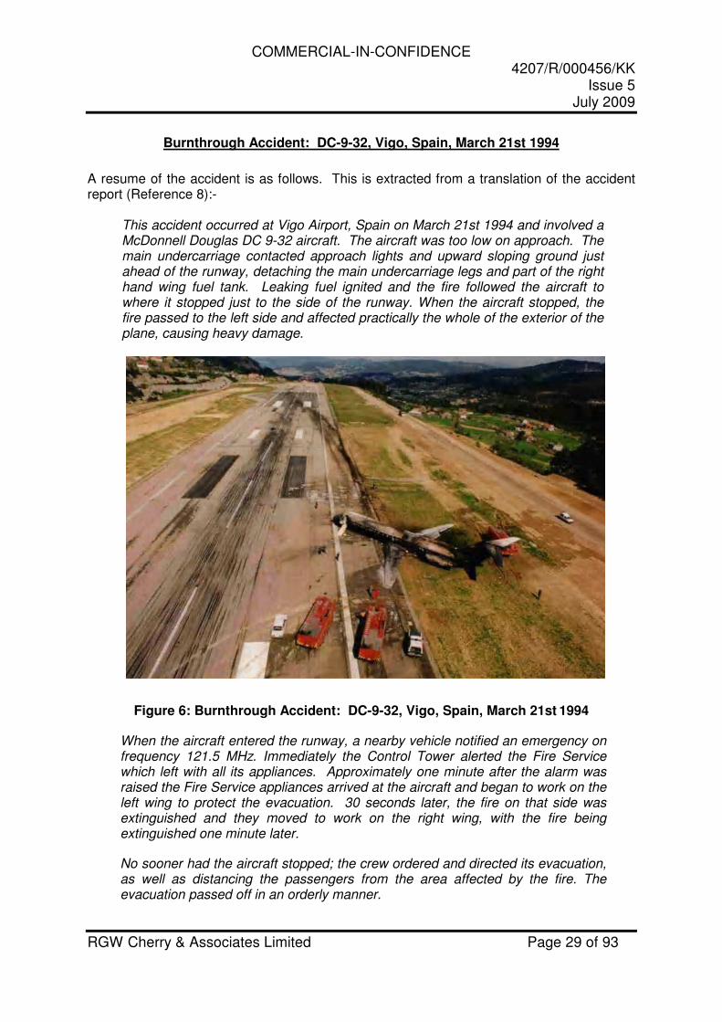
Analysis of the accident data shows that the duration of the main fire was around three minutes. It started when the aircraft came to rest and ceased when it was extinguished on the starboard side. All of the fire damage is considered to have occurred in the three-minute period after the aircraft stopped as any flames present during the ground slide would have trailed behind the aircraft. The extent of fire damage to the exterior of the starboard rear fuselage is shown in Figure 7 and Figure 8. The intense fire burned through the lower fuselage skin revealing the thermal acoustic insulation. Two of the fuselage frames were burned through. The upper half of the fuselage was burned through around and above the cabin windows. However, the extent of burnthrough of the upper fuselage is significantly less than through the lower fuselage.
Figure 7: Vigo DC 9-32 Skin Burnthrough of Lower and Upper Fuselage
COMMERCIAL-IN-CONFIDENCE 4207/R/000456/KK
Issue 5 July 2009
RGW Cherry & Associates Limited Page 31 of 93
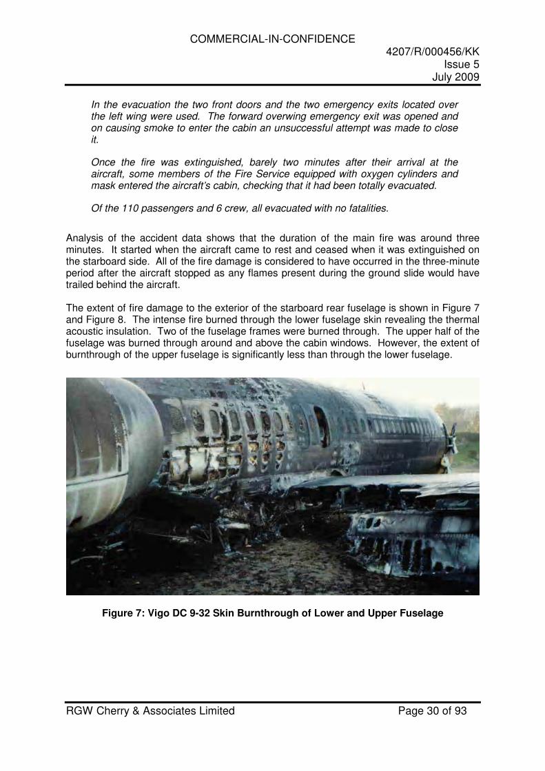
Figure 8: Vigo DC 9-32 External Fire Damage Starboard Side
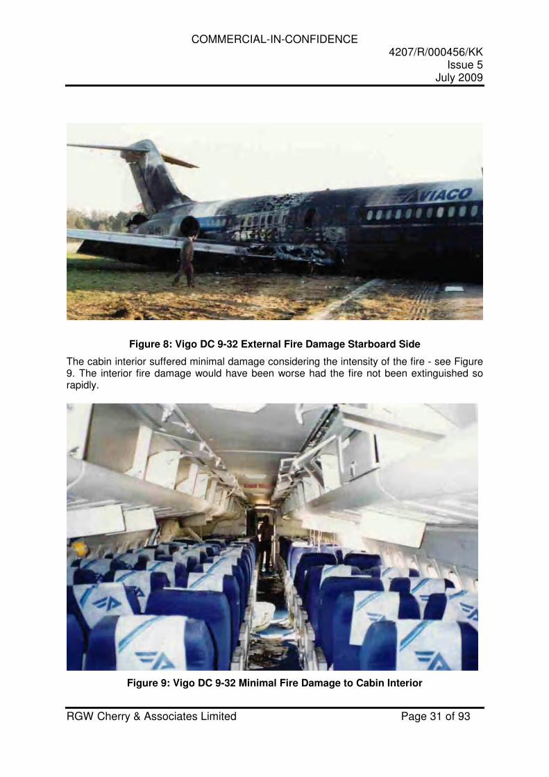
The cabin interior suffered minimal damage considering the intensity of the fire - see Figure 9. The interior fire damage would have been worse had the fire not been extinguished so rapidly.
Figure 9: Vigo DC 9-32 Minimal Fire Damage to Cabin Interior

COMMERCIAL-IN-CONFIDENCE 4207/R/000456/KK
Issue 5 July 2009
RGW Cherry & Associates Limited Page 32 of 93
The starboard Type III overwing exit, opened during the evacuation, allowed fire to enter the cabin and locally scorch the interior materials - see Figure 10.
Figure 10: Vigo DC 9-32 Scorching Near Starboard Overwing Emergency Exit
Figure 11 shows fire damage to the interior cabin materials above the level of the cabin windows. The Spanish accident investigation authority CIAIAC has confirmed the internal fire damage was caused by the external burnthrough above the windows and not from fire entering the Type III Overwing Exit opened during the evacuation.
Figure 11: Vigo DC 9-32 Localized Fire Damage Due to Upper Fuselage Burnthrough
COMMERCIAL-IN-CONFIDENCE 4207/R/000456/KK
Issue 5 July 2009
RGW Cherry & Associates Limited Page 33 of 93
It is evident that in this accident the fire burned through the upper fuselage skin, burned some of the cabin lining materials, and penetrated the cabin in significantly less than 5 minutes. This evidence supports the conclusions gained from the review of the FAA Full Scale Fuselage Burnthrough Tests, confirming that a ground pool fire has the potential to burn through the upper fuselage in less than five minutes given the necessary conditions, namely, a large enough fire which may be exacerbated by wind blowing the flame plume on to the upper skin. Furthermore, it demonstrates that even with a relatively small area of burnthrough in the upper skin, the cabin interior materials can be exposed to enough heat to allow fire penetration into the cabin.
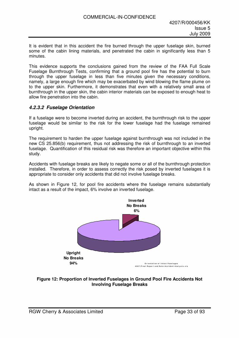
4.2.3.2 Fuselage Orientation If a fuselage were to become inverted during an accident, the burnthrough risk to the upper fuselage would be similar to the risk for the lower fuselage had the fuselage remained upright. The requirement to harden the upper fuselage against burnthrough was not included in the new CS 25.856(b) requirement, thus not addressing the risk of burnthrough to an inverted fuselage. Quantification of this residual risk was therefore an important objective within this study. Accidents with fuselage breaks are likely to negate some or all of the burnthrough protection installed. Therefore, in order to assess correctly the risk posed by inverted fuselages it is appropriate to consider only accidents that did not involve fuselage breaks. As shown in Figure 12, for pool fire accidents where the fuselage remains substantially intact as a result of the impact, 6% involve an inverted fuselage.
O r i e n t a t i o n o f I n t a c t F u s e l a g e s
4 2 0 7 \ F i n a l R e p o r t a n d D a t a \ A c c i d e n t A n a l y s i s . x l s
Inverted
No Breaks
6%
Upright
No Breaks
94%
Figure 12: Proportion of Inverted Fuselages in Ground Pool Fire Accidents Not Involving Fuselage Breaks
COMMERCIAL-IN-CONFIDENCE 4207/R/000456/KK
Issue 5 July 2009
RGW Cherry & Associates Limited Page 34 of 93
Conclusion 6: Although evidence available at this time does not provide a typical or minimum time for upper fuselage burnthrough it appears that it occurs later than lower fuselage burnthrough. In full-scale tests, upper skin burnthrough occurred in as little as 1 minute 40 seconds. Accident evidence shows that upper fuselage burnthrough can occur in less than 3 minutes. The extent of flame impingement on the upper fuselage would depend on the fire location, any shielding effects from the lower fuselage, and any wind effects on the fire plume.
Conclusion 7: A number of accidents have resulted in the fuselage becoming inverted and remaining intact. In this scenario, the fire threat to the upper fuselage is no different to the lower fuselage in normal circumstances.
COMMERCIAL-IN-CONFIDENCE 4207/R/000456/KK
Issue 5 July 2009
RGW Cherry & Associates Limited Page 35 of 93
4.2.4 Cabin Windows
Windows provide a potential route for external fire to penetrate directly into the occupied area of the cabin. Full-scale tests carried out in References 7 and 9 and medium scale tests carried out in Reference 10 show that fire can penetrate cabin windows in well under five minutes. In some accidents, occupants reported seeing flames entering through cabin windows. Cabin windows are typically manufactured from several acrylic panes. The outer pane is the thickest and is required to carry the cyclic cabin pressure loads. It also provides an acoustic barrier. On some aircraft, the thickness may vary along the fuselage length to meet particular acoustic needs. The middle pane is much thinner and is designed to carry the cabin pressure load in the event of failure of the outer pane. The innermost non-structural pane is also thin and acts as a protective barrier to prevent damage to the structural panes. The outer and middle structural panes are normally made from stretched acrylic, which has improved strength properties compared with as-cast acrylic. The thin inner pane is likely to be manufactured from as-cast acrylic. On the majority of aircraft, cabin windows are located in the upper half of the fuselage. Cabin window fire penetration was relevant to this study as it affects the overall evaluation of fuselage burnthrough risk. Test and accident evidence were sought to provide information on cabin window fire penetration times and the failure mechanisms involved.
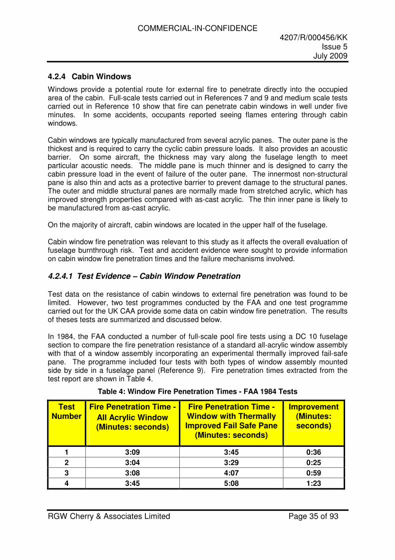
4.2.4.1 Test Evidence – Cabin Window Penetration Test data on the resistance of cabin windows to external fire penetration was found to be limited. However, two test programmes conducted by the FAA and one test programme carried out for the UK CAA provide some data on cabin window fire penetration. The results of theses tests are summarized and discussed below. In 1984, the FAA conducted a number of full-scale pool fire tests using a DC 10 fuselage section to compare the fire penetration resistance of a standard all-acrylic window assembly with that of a window assembly incorporating an experimental thermally improved fail-safe pane. The programme included four tests with both types of window assembly mounted side by side in a fuselage panel (Reference 9). Fire penetration times extracted from the test report are shown in Table 4.
Table 4: Window Fire Penetration Times - FAA 1984 Tests
Test Number
Fire Penetration Time -
All Acrylic Window (Minutes: seconds)
Fire Penetration Time -Window with Thermally Improved Fail Safe Pane
(Minutes: seconds)
Improvement (Minutes: seconds)
1 3:09 3:45 0:36
2 3:04 3:29 0:25
3 3:08 4:07 0:59
4 3:45 5:08 1:23
COMMERCIAL-IN-CONFIDENCE 4207/R/000456/KK
Issue 5 July 2009
RGW Cherry & Associates Limited Page 36 of 93
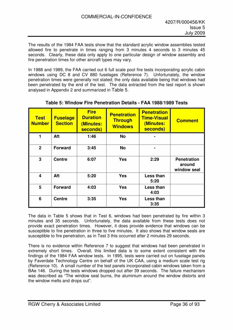
The results of the 1984 FAA tests show that the standard acrylic window assemblies tested allowed fire to penetrate in times ranging from 3 minutes 4 seconds to 3 minutes 45 seconds. Clearly, these data only apply to one particular design of window assembly and fire penetration times for other aircraft types may vary. In 1988 and 1989, the FAA carried out 6 full scale pool fire tests incorporating acrylic cabin windows using DC 8 and CV 880 fuselages (Reference 7). Unfortunately, the window penetration times were generally not stated; the only data available being that windows had been penetrated by the end of the test. The data extracted from the test report is shown
analysed in Appendix 2 and summarized in Table 5.
Table 5: Window Fire Penetration Details - FAA 1988/1989 Tests
Test Number
Fuselage Section
Fire Duration
(Minutes: seconds)
Penetration Through
Windows
Penetration Time-Visual
(Minutes: seconds)
Comment
1 Aft 1:46 No -
2 Forward 3:45 No -
3 Centre 6:07 Yes 2:29 Penetration around
window seal
4 Aft 5:20 Yes Less than 5:20
5 Forward 4:03 Yes Less than 4:03
6 Centre 3:35 Yes Less than 3:35
The data in Table 5 shows that in Test 6, windows had been penetrated by fire within 3 minutes and 35 seconds. Unfortunately, the data available from these tests does not provide exact penetration times. However, it does provide evidence that windows can be susceptible to fire penetration in three to five minutes. It also shows that window seals are susceptible to fire penetration, as in Test 3 this occurred after 2 minutes 29 seconds. There is no evidence within Reference 7 to suggest that windows had been penetrated in extremely short times. Overall, this limited data is to some extent consistent with the findings of the 1984 FAA window tests. In 1995, tests were carried out on fuselage panels by Faverdale Technology Centre on behalf of the UK CAA, using a medium scale test rig (Reference 10). A small number of the test panels incorporated cabin windows taken from a BAe 146. During the tests windows dropped out after 39 seconds. The failure mechanism was described as “The window seal burns, the aluminium around the window distorts and the window melts and drops out”.
COMMERCIAL-IN-CONFIDENCE 4207/R/000456/KK
Issue 5 July 2009
RGW Cherry & Associates Limited Page 37 of 93
4.2.4.2 Accident Evidence – Cabin Window Penetration Eighty-eight ground pool fire accidents were reviewed in this study. For four of these accidents, there are specific accounts of fire, smoke, or heat entering the cabin through melted windows. Evidence describing the degree of deterioration to the cabin environment and estimates, for the time taken for window fire penetration, are shown as follows:
Manchester B737-200, 1985 (ADB Ref 19850822A) - Aborted Take-off following Uncontained Engine Failure - 55 Cabin Fire Fatalities, 137 Occupants
“The flames were seen to cause some 'cracking and melting' of the windows, with some associated smoke in the aft cabin before the aircraft stopped. Another passenger from 6B, after seeing foam being sprayed over the fire on the left side of the aircraft, tried to move into the aisle but it was jammed with people and it was difficult to move. On turning he saw flames shooting in through the side windows and up through the floor area. The flames were several feet in length and continual. It is estimated that the windows resisted penetration by the fire for at least 40 to 50 seconds after the aircraft stopped. However, visible signs of damage to the outer panels, including cracking and apparent melting, were evident much earlier."
An assessment of data for the Manchester B737-200 accident indicates that the windows burned through between 54 and 95 seconds from the fire commencing. This range of times has been derived by assuming the fire onslaught commenced either very soon after the engine disc ruptured the fuel tank or when the passengers on the left side started moving forward as a result of the fire outside (45 and 15 seconds prior to the aircraft stopping respectively). The accident report concluded that the windows were penetrated at least 40 to 50 seconds after the aircraft stopped.
COMMERCIAL-IN-CONFIDENCE 4207/R/000456/KK
Issue 5 July 2009
RGW Cherry & Associates Limited Page 38 of 93
Calgary B737-200, 1984 (ADB Ref 19840322A) - Aborted Take-off following Uncontained Engine Failure - 0 Cabin Fire Fatalities, 119 Occupants
“Shortly after the evacuation commenced, fire melted windows along the left side of the aircraft. When the windows melted through, heat and smoke entered the aircraft, and the cabin environment quickly deteriorated. Substantial quantities of smoke also entered through the right over-wing exit and right rear service door. Conditions within the aircraft cabin were significantly worse in the aft section. Heat was felt as the windows melted through. Those passengers who had been seated beside the windows nearest the fire experienced some singeing of hair and clothing. Aft of seat row 8, flame damage had occurred to the interior of the passenger cabin. Windows had melted or burned away and the fuselage liners and seat upholstery were heavily damaged by fire entering through the window openings.”
An assessment of data for the Calgary B737 accident indicates that the windows burned through in around 2 to 3 minutes. This is derived from the fact that the windows were penetrated soon after the evacuation commenced. The evacuation commenced 1 minute and 55 seconds after the engine disc failed and ruptured the fuel tank. The fire commenced soon after the fuel tank was ruptured.
Kuala Lumpur A300, 1983 (ADB Ref 19831218A) - Impacted Trees and Ground during Approach - 0 Cabin Fire Fatalities, 247 Occupants
“The evacuation of all passengers and crew took approximately 5 minutes. The Captain was the last to leave and when he was at the mid-cabin section he noticed visible smoke in the Aft Cabin. The propagation of the external fire into the cabin via the rear RH fuselage and cabin windows probably took 6 to 9 minutes and cabin flashover throughout the cabin was probably completed in 10 minutes.” “The propagation of the fire was also retarded because of the intense tropical rain and fuel was being dispersed by the floodwater.”
The accident data for the Kuala Lumpur A300 states that fire propagation through the cabin windows probably took 6 to 9 minutes. These burnthrough times appear very high compared with other accidents and are possibly due to the effect of the tropical rain and floodwater.
COMMERCIAL-IN-CONFIDENCE 4207/R/000456/KK
Issue 5 July 2009
RGW Cherry & Associates Limited Page 39 of 93
Los Angeles DC 10, 1978 (ADB Ref 19780301A) - Overrun following Aborted Take-off - 0 Cabin Fire Fatalities, 200 Occupants
The structural integrity of the cabin was not compromised, since the entire fuselage remained intact and the fire remained outside the fuselage. Some smoke penetrated the cabin area but did not hinder successful evacuation. The only seats sustaining thermal damage were 18A, 18B, 24A and 24B, and the flight attendant's seat at L3. This damage was probably caused by radiant heat entering the cabin through the L3 exit and through the cabin windows when they melted. Most of the windows between L3 and L4 were melted and burned. Little or no evidence of fire penetration was noted at these open windows.
An assessment of data for the Los Angeles DC 10 accident suggests that although the windows were melted within 6 minutes they had withstood the fire onslaught for much of that time. This time is based on the fire duration of around 6 minutes, which is derived from the fact that the second wave of fire fighting vehicles arrived 4 minutes after the accident and the fire was extinguished 2 minutes after they arrived.)
Conclusion 8 : The fire penetration of acrylic windows is possible in around 1 minute to 3 minutes depending on the design. Fire penetration of windows has been cited as a major reason for rapid deterioration of the cabin environment in several accident reports. Cabin window fire penetration resistance is likely to be influenced by thickness, installation details, and material properties. Little research appears to have been conducted into the fire penetration resistance of cabin windows, and further research may be beneficial. Cabin windows could potentially prevent fire penetration for at least 4 minutes if the design is optimised, but there could be weight penalties.
COMMERCIAL-IN-CONFIDENCE 4207/R/000456/KK
Issue 5 July 2009
RGW Cherry & Associates Limited Page 40 of 93
4.2.5 Fire threats not mitigated by Enhanced Fuselage Burnthrough Protection
The potential fire threats from fuselage breaks, ruptures, or opened doors cannot be improved via enhanced fuselage burnthrough protection. They are considered together in this section of the report since their significance is that they result in there being a limit on the level of protection that may be afforded by fuselage hardening.
4.2.5.1 Breaks and Ruptures Fuselage breaks or ruptures may occur as a result of the impact sequence and provide a possible fire entry route into the cabin. For the purposes of this study, a break is considered sufficiently large to allow occupants to evacuate through whereas a rupture may be large enough to allow fire entry but not large enough to allow occupant escape. A study commissioned by the FAA (Reference 11) concluded:
“The occurrence of a Fuselage Break in ground pool fire accidents seems to result in a more severe fire threat to the occupants. However, it is evident that for the majority of ground pool fire accidents studied, involving a Fuselage Break, the occupants used the breaks as an escape route. In order to ascertain the net effects of Fuselage Breaks on occupant survival a Monte Carlo simulation model was developed. The primary value of the model was an assessment of the effects on occupant survival of changes in the probability of occurrence of Fuselage Breaks. Based on the results derived from the model it is considered that Fuselage Breaks have a net adverse effect on occupant survival. “
The study (Reference 11) suggests that fuselage breaks have a net adverse effect on occupant survival. However, the study was based on limited data and hence no firm determination could be made as to whether the increase in fatalities was attributable to the more severe impact intensity sustained in fuselage break accidents or due to the encroachment of fire into the cabin.
COMMERCIAL-IN-CONFIDENCE 4207/R/000456/KK
Issue 5 July 2009
RGW Cherry & Associates Limited Page 41 of 93
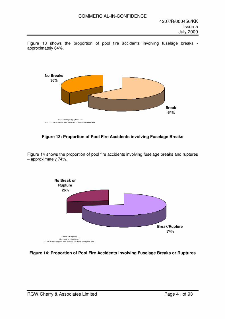
Figure 13 shows the proportion of pool fire accidents involving fuselage breaks - approximately 64%.
C a b i n I n t e g r i t y ( B r e a k s )
4 2 0 7 \ F i n a l R e p o r t a n d D a t a \ A c c i d e n t A n a l y s i s . x l s
No Breaks
36%
Break
64%
Figure 13: Proportion of Pool Fire Accidents involving Fuselage Breaks
Figure 14 shows the proportion of pool fire accidents involving fuselage breaks and ruptures – approximately 74%.
C a b i n I n t e g r i t y
( B r e a k s o r R u p t u r e s )
4 2 0 7 \ F i n a l R e p o r t a n d D a t a \ A c c i d e n t A n a l y s i s . x l s
Break/Rupture
74%
No Break or
Rupture
26%
Figure 14: Proportion of Pool Fire Accidents involving Fuselage Breaks or Ruptures
COMMERCIAL-IN-CONFIDENCE 4207/R/000456/KK
Issue 5 July 2009
RGW Cherry & Associates Limited Page 42 of 93
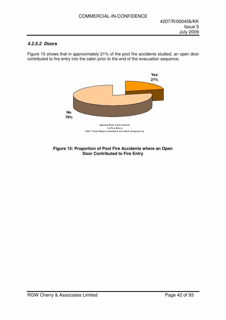
4.2.5.2 Doors Figure 15 shows that in approximately 21% of the pool fire accidents studied, an open door contributed to fire entry into the cabin prior to the end of the evacuation sequence.
Ope ne d D oor Cont r i but e d
t o Fi r e Ent r y
4 2 0 7 \ Fi na l R e por t a nd D a t a \ A c c i de nt A na y sis. x l s
Yes
21%
No
79%
Figure 15: Proportion of Pool Fire Accidents where an Open Door Contributed to Fire Entry
COMMERCIAL-IN-CONFIDENCE 4207/R/000456/KK
Issue 5 July 2009
RGW Cherry & Associates Limited Page 43 of 93
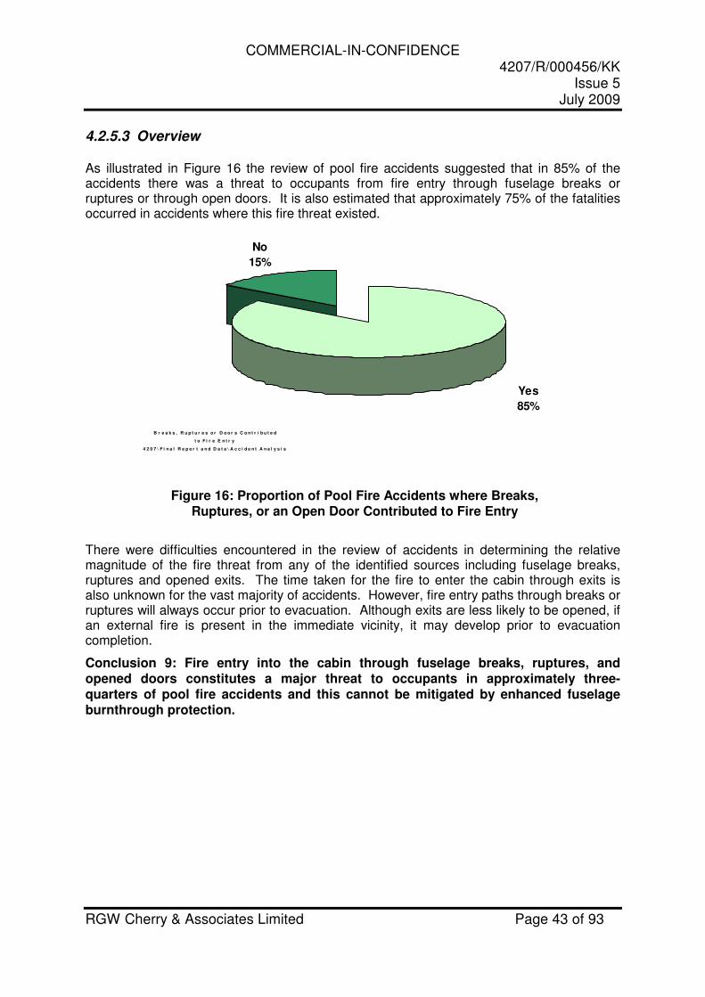
4.2.5.3 Overview As illustrated in Figure 16 the review of pool fire accidents suggested that in 85% of the accidents there was a threat to occupants from fire entry through fuselage breaks or ruptures or through open doors. It is also estimated that approximately 75% of the fatalities occurred in accidents where this fire threat existed.
B r e a k s , R u p t u r e s o r D o o r s C o n t r i b u t e d
t o F i r e E n t r y
4 2 0 7 \ F i n a l R e p o r t a n d D a t a \ A c c i d e n t A n a l y s i s
No
15%
Yes
85%
Figure 16: Proportion of Pool Fire Accidents where Breaks, Ruptures, or an Open Door Contributed to Fire Entry
There were difficulties encountered in the review of accidents in determining the relative magnitude of the fire threat from any of the identified sources including fuselage breaks, ruptures and opened exits. The time taken for the fire to enter the cabin through exits is also unknown for the vast majority of accidents. However, fire entry paths through breaks or ruptures will always occur prior to evacuation. Although exits are less likely to be opened, if an external fire is present in the immediate vicinity, it may develop prior to evacuation completion.
Conclusion 9: Fire entry into the cabin through fuselage breaks, ruptures, and opened doors constitutes a major threat to occupants in approximately three-quarters of pool fire accidents and this cannot be mitigated by enhanced fuselage burnthrough protection.
COMMERCIAL-IN-CONFIDENCE 4207/R/000456/KK
Issue 5 July 2009
RGW Cherry & Associates Limited Page 44 of 93
4.2.6 Installation of Thermal Acoustic Insulation
The burnthrough protection rule CS 25.856(b) addresses the burnthrough properties required of Thermal Acoustic Insulation. However, there are currently no burnthrough protection requirements for areas of the aircraft where Thermal Acoustic Insulation is not installed. However, most aircraft will have Thermal Acoustic Insulation installed over the vast majority of the cabin. If this is to act as a barrier to pool fires penetrating into the cabin, then it must be installed in accord with criteria established from testing, for it to become fully effective. The importance of the installation aspects of Thermal Acoustic Insulation, in their ability to act as a fire barrier, was confirmed in testing carried out for the UK Civil Aviation Authority by Darchem Flare (Reference 12). Extensive research had been carried out by Darchem Flare over a period of years following the B737 accident at Manchester (Reference 3). As part of this research a medium scale test rig was developed that was representative of a ground pool fire. A Darchem Flare study addressing the installation aspects of Thermal Acoustic Insulation was carried out in order to provide data for the FAA to include in their Advisory Circular relating to burnthrough (Reference 13). The Darchem Flare study (Reference 12) concludes in relation to the installation of Thermal Acoustic Insulation:
“The extensive testing carried out under this research programme has shown that extended periods of protection (up to 900 seconds) may be achieved when burnthrough resistant materials are installed. However, the attainment of these high levels of protection is totally dependent on the characteristics of the installation.”
4.2.6.1 Attachment Means & Effects of Protective Treatments Significant aspects of the installation are the means used for attaching the Thermal Acoustic Insulation to the aircraft structure and the protective treatments likely to be present on the aircraft skin, stringers, and frames. This is summarised in the following conclusions contained in Reference 12:
“The body of testing, as referenced in this document, has shown consistently that any gaps in the insulation material, close to the fuselage skin, will result in rapid flame penetration into the cabin. It is therefore essential that the thermal acoustic liner installation is such that it restricts the passage of gases and subsequent flame penetration through to the cold side of the insulation bag. The presence of protective coatings and corrosion inhibitors on the aircraft structure appears to have an adverse effect on the capability of an installation to achieve the levels of protection suggested by the testing carried out on stylised panels. The areas of the installation that seem to be particularly vulnerable are at the insulation bag overlap.”
The Darchem Flare study showed conclusively that the means by which the Thermal Acoustic Insulation is attached to the aircraft structure is vital to its ability to act as a fire
COMMERCIAL-IN-CONFIDENCE 4207/R/000456/KK
Issue 5 July 2009
RGW Cherry & Associates Limited Page 45 of 93
barrier. Whilst these aspects are addressed in the FAA Advisory Circular (Reference 13), it is feasible that maintenance activity on the aircraft could compromise the level of protection afforded. Another significant aspect revealed from the Darchem Flare testing was that the presence of protective coatings and corrosion inhibitors could compromise the level of protection from pool fires afforded by Thermal Acoustic Insulation. This issue is not accommodated by the FAA test method for Thermal Acoustic Insulation.
4.2.6.2 Discontinuities CS 25.856(b) allows gaps to remain in the insulation that might introduce potential fire paths. These discontinuities in the protection include slots, holes, pass-throughs, structural joins, and other openings. The FAA has conducted tests to determine an acceptable level of discontinuities to ensure safety (Reference 14). FAA Advisory Circular (Reference 13) includes the following note regarding discontinuities:
“Certain discontinuities are unavoidable: for example, where essential systems must go from the outboard to the inboard side of the insulation material, and such systems cannot practically be constructed of fire-resistant material themselves. Since the regulation does not mandate installation of thermal/acoustic insulation, such discontinuities cannot be prohibited, although their occurrences should be minimized. Such discontinuities need not be considered in the test samples. The rule, however, does require consideration of the installation design methodology, so discontinuities in the insulation would not be acceptable if they are caused by the installation design methodology”.
Although the Advisory Circular (Reference 13) addresses the need to minimise discontinuities it provides limited guidance relating to unacceptable discontinuities. Based on the Darchem Flare testing described in Reference 12 “…any gaps in the insulation material, close to the fuselage skin, will result in rapid flame penetration into the cabin.”
Conclusion 10: There are currently no burnthrough protection requirements for areas of the aircraft where Thermal Acoustic Insulation is not installed. The use of Thermal Acoustic Insulation as a means of protecting the cabin from pool fires may be compromised by any gaps that might exist in the fire protection barrier. These gaps may result from discontinuities in the protection afforded by Thermal Acoustic Insulation or from degradation of the attachment means whilst the aircraft is in-service. The presence of protective coatings and corrosion inhibitors may also reduce the level of protection afforded by Thermal Acoustic Insulation. This aspect is not addressed in the current rule.

COMMERCIAL-IN-CONFIDENCE 4207/R/000456/KK
Issue 5 July 2009
RGW Cherry & Associates Limited Page 46 of 93
4.2.7 Frame Collapse
The integrity of a flame penetration resistant barrier installed to protect the fire entering the pressure shell is dependent on the fuselage frames not burning through thereby allowing the barrier to become detached or fall out. Where insulation blankets are used to provide the barrier they are clipped firmly to the frames allowing flexibility to conform to the frame profile. Once the fuselage skin has melted, the frames would therefore be protected by the insulation blanket. However, some aircraft are insulated with rigid foam blocks that slot between the fuselage frames. This type of installation may be designed with a large gap between the outermost face of the insulation block and the fuselage skin. Consequently, the frames are not protected by the fire barrier, as they would be with insulation blankets. They would become directly exposed to the fire once the skin has melted as shown in Figure 17. Whilst the foam block insulation may be capable of resisting burnthrough, it may not prevent the fuselage frames from melting and collapsing, thereby allowing the fire barrier to fall out of the fuselage.
Figure 17: Typical Installation of Foam Block Insulation System
The FAA Advisory Circular (Reference 13) contains extensive guidance on the acceptable means of installation of insulation blankets, which is based on extensive research and testing. It does not contain similar guidance for the installation of rigid foam systems. The FAA kerosene burner test incorporates steel frames and stringers, which are intended not to burn through. However, the Advisory Circular includes the requirement for aircraft manufacturers to modify the test frame by incorporating a defined area of aluminium alloy components when the type of insulation or its installation method does not comply with the guidance given for flexible insulation blankets. It states:
“If the test fixture needs to be modified in order to address material and/or installation schemes not anticipated by the rule, the existing vertical steel frame is replaced with an aluminum frame. Similarly, two of the steel horizontal stringers are replaced with aluminum stringers. This methodology allows the aluminum members to melt and fail with the realism of an actual aircraft fuselage during a post-crash fire scenario. Under these conditions, not only are the blanket materials being tested, but the ability of the insulation system for preventing flame penetration is examined.”
Skin
Foam Block Insulation
Frame
Fire Entry through Skin Impinges Directly on Frames
Skin
Frame
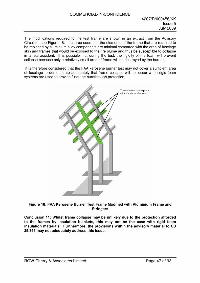
COMMERCIAL-IN-CONFIDENCE 4207/R/000456/KK
Issue 5 July 2009
RGW Cherry & Associates Limited Page 47 of 93
The modifications required to the test frame are shown in an extract from the Advisory Circular - see Figure 18. It can be seen that the elements of the frame that are required to be replaced by aluminium alloy components are minimal compared with the area of fuselage skin and frames that would be exposed to the fire plume and thus be susceptible to collapse in a real accident. It is possible that during the test, the rigidity of the foam will prevent collapse because only a relatively small area of frame will be destroyed by the burner. It is therefore considered that the FAA kerosene burner test may not cover a sufficient area of fuselage to demonstrate adequately that frame collapse will not occur when rigid foam systems are used to provide fuselage burnthrough protection.
Figure 18: FAA Kerosene Burner Test Frame Modified with Aluminium Frame and Stringers
Conclusion 11: Whilst frame collapse may be unlikely due to the protection afforded to the frames by insulation blankets, this may not be the case with rigid foam insulation materials. Furthermore, the provisions within the advisory material to CS 25.856 may not adequately address this issue.
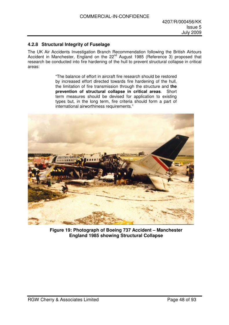
COMMERCIAL-IN-CONFIDENCE 4207/R/000456/KK
Issue 5 July 2009
RGW Cherry & Associates Limited Page 48 of 93
4.2.8 Structural Integrity of Fuselage
The UK Air Accidents Investigation Branch Recommendation following the British Airtours Accident in Manchester, England on the 22
nd August 1985 (Reference 3) proposed that
research be conducted into fire hardening of the hull to prevent structural collapse in critical areas:
“The balance of effort in aircraft fire research should be restored by increased effort directed towards fire hardening of the hull, the limitation of fire transmission through the structure and the prevention of structural collapse in critical areas. Short term measures should be devised for application to existing types but, in the long term, fire criteria should form a part of international airworthiness requirements.”
Figure 19: Photograph of Boeing 737 Accident – Manchester England 1985 showing Structural Collapse
COMMERCIAL-IN-CONFIDENCE 4207/R/000456/KK
Issue 5 July 2009
RGW Cherry & Associates Limited Page 49 of 93
A study carried out for the UK CAA in 1998 (Reference 15) concluded:
“The structural strength of the aircraft, exposed to a pool fire, did not appear to have a significant effect on occupant survival. Although there was limited data available only two accidents (Los Angeles and Manchester) were positively identified as involving structural collapse. Structural failure occurred at 18 minutes for Los Angeles, and hence was not a factor in occupant survival. As previously discussed it is assessed that there is limited benefit to be gained beyond 8 minutes [of additional burnthrough protection time]. There is insufficient data available to ascertain the time that structural collapse occurred for the Manchester accident. Confirmation that structural strength is not a factor in burnthrough accidents is important. If confirmed changes intended to fire harden the fuselage do not need to take into account the residual structural strength.”
As part of this EASA study, the 88 fuselage burnthrough accidents listed in Table A.1-9 of Appendix 1 were reviewed to determine whether more recent data supported the assertion that the structural strength of the aircraft, exposed to a pool fire, did not appear to have a significant effect on occupant survival. Of the 88 accidents reviewed there were no further instances identified where fuselage structural collapse due to burnthrough had a significant effect on occupant survival.
Conclusion 12: The structural strength of the aircraft fuselage resulting from fuselage burnthrough does not appear to have a significant effect on occupant survival.
COMMERCIAL-IN-CONFIDENCE 4207/R/000456/KK
Issue 5 July 2009
RGW Cherry & Associates Limited Page 50 of 93
4.3 ADVANCES IN TECHNOLOGY
4.3.1 Non-metallic Fuselages
4.3.1.1 General New materials are increasingly being utilised on modern aircraft designs for the fuselage skin. The Boeing 787 uses a high proportion of Carbon Fibre Reinforced Polymer (CFRP) for its fuselage skin, while Airbus has selected a glass-reinforced fibre metal laminate called GLARE® for much of the upper fuselage skin of the A380. These composite and laminate materials have a number of significant advantages over traditional aluminium, including improved fire resistance. Carbon Fibre Reinforced Polymer tends to maintain its structural integrity during burning. Carbon fibres make up the bulk of the mass of CFRP, and as these are essentially inert, a CFRP panel burns in a similar manner to a ‘charring’ material (Reference 16). The resin used to reinforce the fibres, however, vaporises causing the material to swell to up to twice its volume. The charred fibres create an insulating layer, reducing the internal heating and burning rate. GLARE®, which uses alternating layers of aluminium and glass-fibre bonded together using an epoxy resin, also seems to provide a superior fire resistance to aluminium. While the exposed aluminium layer melts, the epoxy around the underlying glass fibres carbonises – protecting the remaining aluminium layers. The cold face temperature is reportedly reduced by more than half due to the isolating effect of the delaminated glass fibre layers (Reference 17). Boeing has conducted testing on the use of GLARE® as a cargo liner material against the requirements of FAR 25.855. Sample lay-ups with thickness between 0.7 mm (0.026”) and 1.4 mm (0.054”) were tested against an 1100 deg C flame and showed no flame penetration after 15 minutes exposure (Reference 18). While GLARE®, used for fuselage skins is likely to be a different grade, this does demonstrate its potential to provide good fire penetration resistance. In each case, while the mechanism described above for the fire resistance properties of composites and laminates is publically disclosed, it has not been possible to obtain detailed test data for burnthrough of samples representative of fuselage skins. Whilst it is not disputed that composites and laminates have improved fire resistance over aluminium, it has not been possible in this study to determine the extent to which these advanced materials will delay burnthrough from a typical ground pool fire.
4.3.1.2 Current Applications Composite or laminate materials are used in the fuselage skin of the Boeing 787 and the Airbus A380. When used for the entire fuselage skin, the improved fire resistance could help to protect both the lower and upper skin from burnthrough. On the A380, Airbus is promoting the improved safety provided by GLARE® on the upper half of the fuselage, and protecting the lower portion through the application of burnthrough resistant insulation blankets (Reference 19). Future designs are likely to increase the trend in using composites or laminates, with the future Airbus A350 design using Carbon Fibre Reinforced Polymer for its fuselage skin.
COMMERCIAL-IN-CONFIDENCE 4207/R/000456/KK
Issue 5 July 2009
RGW Cherry & Associates Limited Page 51 of 93
Conclusion 13: Non-metallic fuselages are considered likely to provide improved burnthrough characteristics to aluminium fuselages; however, test data confirming this has not been identified during the course of this study.
COMMERCIAL-IN-CONFIDENCE 4207/R/000456/KK
Issue 5 July 2009
RGW Cherry & Associates Limited Page 52 of 93
4.3.2 External Fuselage Coatings
Intumescent coatings, if applied to the exterior surface of an aluminium-alloy fuselage skin, could potentially provide protection against burnthrough from a pool fire. These coatings are designed to swell significantly when exposed to fire, thereby providing a layer of insulation that delays the temperature rise and subsequent destruction of the substrate material. Intumescent coatings are used extensively in building structures and on aircraft engine firewalls. Several manufacturers of this type of coating have explored their potential for use as an external fuselage burnthrough barrier. One manufacturer has demonstrated the excellent burnthrough performance of an intumescent coating in conjunction with the FAA, utilising a full-scale fuselage. The performance of the coating was observed by a number of aircraft manufacturers and a number of distinct advantages and disadvantages are apparent:
Advantages
� Complete and continuous coverage of the fuselage skin with no discontinuities � No requirement for complex internal fire protection barriers � Potential weight savings
Disadvantages
� Unproven durability against environmental degradation (UV, contamination etc) � Unproven durability from in service wear and tear � Inferior surface finish may result in aerodynamic issues � Removal of the coating in accidents involving scraping of the fuselage
One manufacturer noted that to provide adequate durability against environmental degradation the intumescent coating would require to be protected with an additional coating, seriously degrading the fire protection properties. It was also noted that intumescent coatings with a very smooth finish do exist, but they need to be applied as a powder coating requiring oven curing at 150°C. This is likely to be impractical for a complete aircraft fuselage. It is likely that the primary disadvantage is the lack of ability for an external fire barrier to withstand damage in an accident. The vast majority of accidents resulting in a ground pool fire involve a ground slide with the landing gear separated or retracted. Whilst any damaged area of the coating may be protected from fire by the ground, this cannot be guaranteed and would be virtually impossible to demonstrate. The only ground pool fire accidents where an external intumescent coating would be totally effective are those where the aircraft remains on its undercarriage and the fuselage has not suffered scraping. In this study, 88 pool fire accidents were reviewed, and for those accidents where fire entered the cabin, the aircraft remained on its landing gear and had no ruptures in only 4 %.
Conclusion 14: Intumescent coatings are unlikely to prove feasible as the primary means of providing fuselage burnthrough protection when applied externally. However, protection of the cabin by coating internal features such as the underside of the cabin floor may be very feasible and this area is considered worthy of further research.
COMMERCIAL-IN-CONFIDENCE 4207/R/000456/KK
Issue 5 July 2009
RGW Cherry & Associates Limited Page 53 of 93
4.4 SUMMARY OF CONCLUSIONS
Conclusion 1: On the assumption that an average time for establishing the fire threat and
penetrating the skin of a metallic aircraft is approximately one minute, an additional
burnthrough protection time of 4 minutes is likely to provide adequate occupant
protection for the majority of pool fire threats. ............................................................. 18
Conclusion 2: There are many potential fire paths that exist through to the cabin from a pool
fire. It is likely that the quickest fire paths present in an aircraft subjected to a ground
pool fire are the cheek area in the lower fuselage, the upper fuselage skin, and
windows. However, no conclusions can be reached regarding the relative threat posed
by each of the potential fire paths. .............................................................................. 22
Conclusion 3: Lower skin burnthrough is possible in 15 – 60 seconds, depending on skin
thickness. Air return grills, if present, provide an easy path for smoke and fire to
penetrate the cabin following burnthrough of the lower skin. ....................................... 24
Conclusion 4: In areas of the fuselage having a cargo bay, the presence of liners will still
allow fire to reach the air return grills, but may prevent the fire from accessing the cabin
floor............................................................................................................................. 24
Conclusion 5: Equipment bays might have un-insulated fuselage skin, and if so, would not
benefit from the additional fire penetration resistance afforded by insulation. Fire
burnthrough into equipment bays gives the fire direct access to the fuselage floor or air
return grills. ................................................................................................................. 24
Conclusion 6: Although evidence available at this time does not provide a typical or
minimum time for upper fuselage burnthrough it appears that it occurs later than lower
fuselage burnthrough. In full-scale tests, upper skin burnthrough occurred in as little as
1 minute 40 seconds. Accident evidence shows that upper fuselage burnthrough can
occur in less than 3 minutes. The extent of flame impingement on the upper fuselage
would depend on the fire location, any shielding effects from the lower fuselage, and
any wind effects on the fire plume. .............................................................................. 34
Conclusion 7: A number of accidents have resulted in the fuselage becoming inverted and
remaining intact. In this scenario, the fire threat to the upper fuselage is no different to
the lower fuselage in normal circumstances................................................................ 34
Conclusion 8 : The fire penetration of acrylic windows is possible in around 1 minute to 3
minutes depending on the design. Fire penetration of windows has been cited as a
major reason for rapid deterioration of the cabin environment in several accident
reports. Cabin window fire penetration resistance is likely to be influenced by
COMMERCIAL-IN-CONFIDENCE 4207/R/000456/KK
Issue 5 July 2009
RGW Cherry & Associates Limited Page 54 of 93
thickness, installation details, and material properties. Little research appears to have
been conducted into the fire penetration resistance of cabin windows, and further
research may be beneficial. Cabin windows could potentially prevent fire penetration
for at least 4 minutes if the design is optimised, but there could be weight penalties. . 39
Conclusion 9: Fire entry into the cabin through fuselage breaks, ruptures, and opened doors
constitutes a major threat to occupants in approximately three-quarters of pool fire
accidents and this cannot be mitigated by enhanced fuselage burnthrough protection.
.................................................................................................................................... 43
Conclusion 10: There are currently no burnthrough protection requirements for areas of the
aircraft where Thermal Acoustic Insulation is not installed. The use of Thermal
Acoustic Insulation as a means of protecting the cabin from pool fires may be
compromised by any gaps that might exist in the fire protection barrier. These gaps
may result from discontinuities in the protection afforded by Thermal Acoustic
Insulation or from degradation of the attachment means whilst the aircraft is in-service.
The presence of protective coatings and corrosion inhibitors may also reduce the level
of protection afforded by Thermal Acoustic Insulation. This aspect is not addressed in
the current rule. ........................................................................................................... 45
Conclusion 11: Whilst frame collapse may be unlikely due to the protection afforded to the
frames by insulation blankets, this may not be the case with rigid foam insulation
materials. Furthermore, the provisions within the advisory material to CS 25.856 may
not adequately address this issue. .............................................................................. 47
Conclusion 12: The structural strength of the aircraft fuselage resulting from fuselage
burnthrough does not appear to have a significant effect on occupant survival........... 49
Conclusion 13: Non-metallic fuselages are considered likely to provide improved
burnthrough characteristics to aluminium fuselages; however, test data confirming this
has not been identified during the course of this study................................................ 51
Conclusion 14: Intumescent coatings are unlikely to prove feasible as the primary means of
providing fuselage burnthrough protection when applied externally. However,
protection of the cabin by coating internal features such as the underside of the cabin
floor may be very feasible and this area is considered worthy of further research....... 52
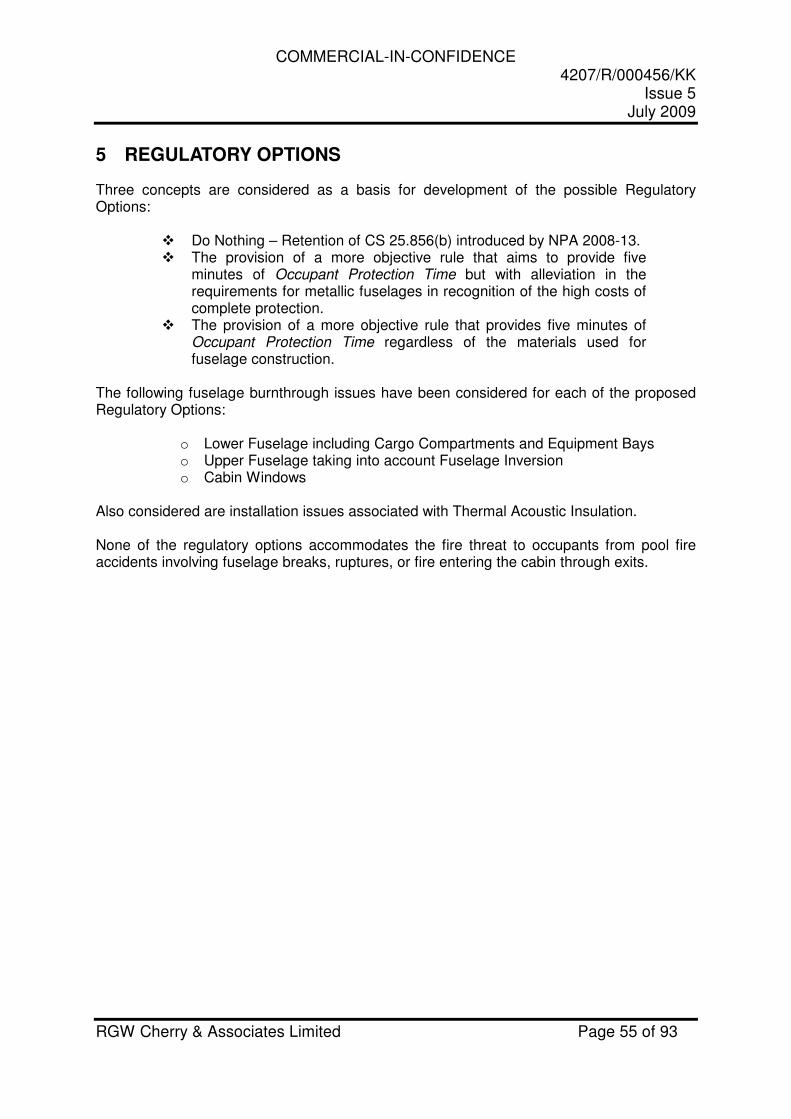
COMMERCIAL-IN-CONFIDENCE 4207/R/000456/KK
Issue 5 July 2009
RGW Cherry & Associates Limited Page 55 of 93
5 REGULATORY OPTIONS
Three concepts are considered as a basis for development of the possible Regulatory Options:
� Do Nothing – Retention of CS 25.856(b) introduced by NPA 2008-13. � The provision of a more objective rule that aims to provide five
minutes of Occupant Protection Time but with alleviation in the requirements for metallic fuselages in recognition of the high costs of complete protection.
� The provision of a more objective rule that provides five minutes of Occupant Protection Time regardless of the materials used for fuselage construction.
The following fuselage burnthrough issues have been considered for each of the proposed Regulatory Options:
o Lower Fuselage including Cargo Compartments and Equipment Bays o Upper Fuselage taking into account Fuselage Inversion o Cabin Windows
Also considered are installation issues associated with Thermal Acoustic Insulation. None of the regulatory options accommodates the fire threat to occupants from pool fire accidents involving fuselage breaks, ruptures, or fire entering the cabin through exits.

COMMERCIAL-IN-CONFIDENCE 4207/R/000456/KK
Issue 5 July 2009
RGW Cherry & Associates Limited Page 56 of 93
5.1 OPTIONS TO BE CONSIDERED
It is proposed that three regulatory options be considered:
1. Do Nothing – Retention of CS 25.856(b) introduced by NPA 2008-13.
• The “Do nothing” option means to make no improvements to CS-25 in relation to improved burnthrough protection i.e. future aircraft would only need to provide the level of protection afforded by CS 25.856(b).
• Aircraft with non-metallic structures may be addressed by an Equivalent Level of Safety finding.
2. Amend CS-25 to provide a partially objective rule to provide 5 minutes of Occupant
Protection Time in pool fire accidents. For aircraft with metallic fuselages, compliance may be demonstrated with the current standard defined in CS 25.856(b), which gives partial protection to the lower fuselage, enhanced to accommodate some of the identified fire threats as defined in a) below. For aircraft with non-metallic fuselages 5 minutes of Occupant Protection Time is required for the complete cabin, as defined in b) below.
The intention of this proposed option is that it gives greater scope to the aircraft manufacturer to decide how the fuselage should be protected and provides enhanced protection to occupants from the threat of fire penetration. a) Aircraft with Metallic Fuselages Compliance with the FAA rule would be an acceptable means of compliance. Additionally, windows should meet a Burnthrough Test Time of 4 minutes and the upper boundary of the lower fuselage redefined to be at the top of the cabin window line. Guidance Material will provide proposed means for mitigating the effects of burnthrough protection through equipment bays, cargo bays and via discontinuities and gaps in thermal acoustic insulation materials. This Guidance Material will propose that all fire paths through to the cabin from the lower fuselage are identified and where practical the threat is mitigated to an acceptable level. b) Aircraft with Non-Metallic Fuselages Five minutes of Occupant Protection Time should be provided. The Burnthrough Test Time for the lower fuselage should be five minutes and four minutes for the upper fuselage and windows. The upper boundary of the lower fuselage is redefined to be at the top of the cabin window line. Guidance Material will provide proposed means for mitigating the effects of burnthrough. This Guidance Material will propose that all fire paths through to the cabin from the lower and upper fuselage are identified and where practical the threat is mitigated to an acceptable level.
3. Amend CS-25 to provide an Objective rule to provide 5 minutes of Occupant Protection Time in pool fire accidents on all aircraft.
The intention of this proposed option is that it gives greater scope to the aircraft manufacturer to decide how the fuselage should be protected and provides enhanced protection to occupants from the threat of fire penetration. Five minutes of Occupant
COMMERCIAL-IN-CONFIDENCE 4207/R/000456/KK
Issue 5 July 2009
RGW Cherry & Associates Limited Page 57 of 93
Protection Time should be provided. The Burnthrough Test Time for the lower fuselage should be five minutes and four minutes for the upper fuselage and windows. The upper boundary of the lower fuselage is redefined to be at the top of the cabin window line. Guidance Material will provide proposed means for mitigating the effects of burnthrough protection. This Guidance Material will propose that all fire paths through to the cabin from the lower and upper fuselage are identified and where practical the threat is mitigated to an acceptable level.
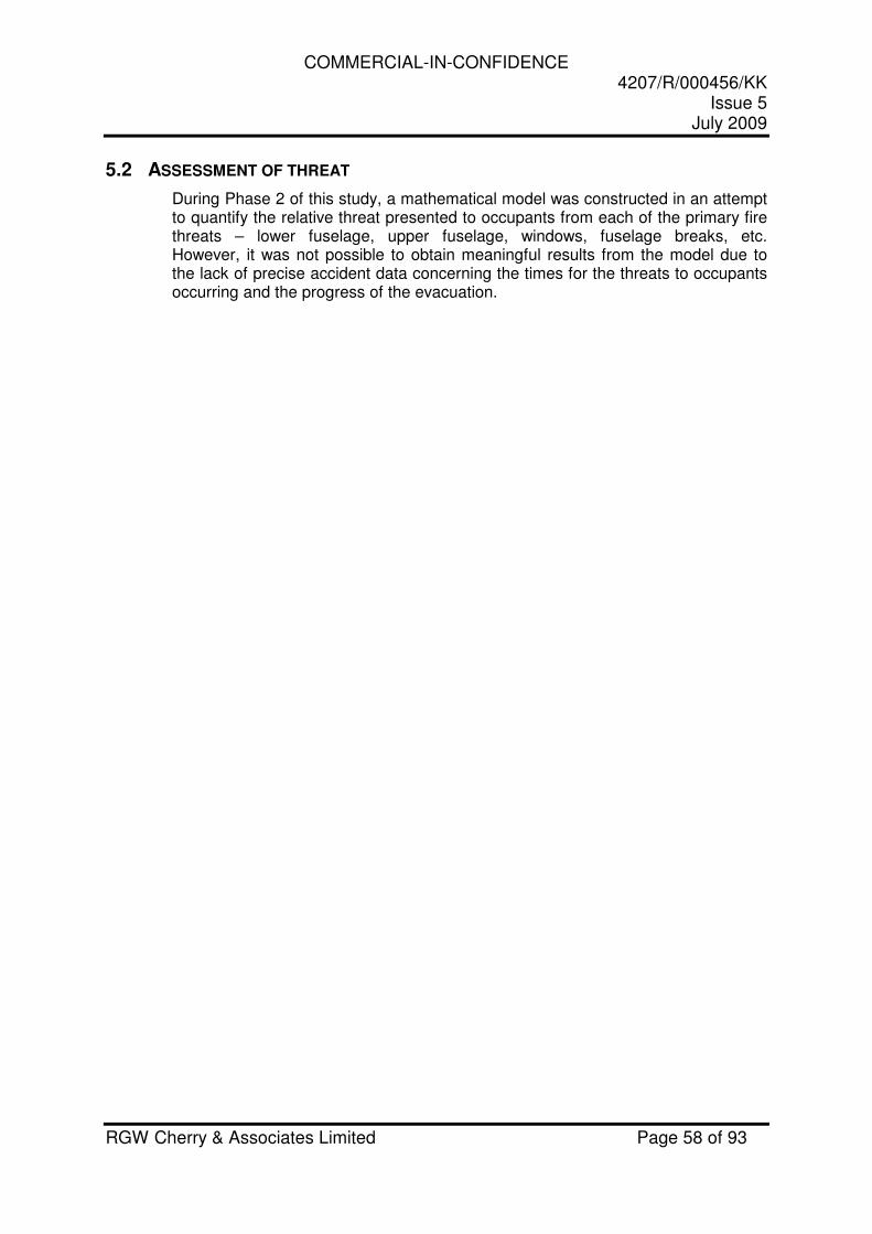
COMMERCIAL-IN-CONFIDENCE 4207/R/000456/KK
Issue 5 July 2009
RGW Cherry & Associates Limited Page 58 of 93
5.2 ASSESSMENT OF THREAT
During Phase 2 of this study, a mathematical model was constructed in an attempt to quantify the relative threat presented to occupants from each of the primary fire threats – lower fuselage, upper fuselage, windows, fuselage breaks, etc. However, it was not possible to obtain meaningful results from the model due to the lack of precise accident data concerning the times for the threats to occupants occurring and the progress of the evacuation.
COMMERCIAL-IN-CONFIDENCE 4207/R/000456/KK
Issue 5 July 2009
RGW Cherry & Associates Limited Page 59 of 93
6 REGULATORY IMPACT ASSESSMENT
Phase 3 of the study has evaluated the proposed regulatory options contained in Section 5 and a Regulatory Impact Assessment has been produced as a stand-alone document (Reference 20). The methodology used follows the guidelines contained in Reference 2.
COMMERCIAL-IN-CONFIDENCE 4207/R/000456/KK
Issue 5 July 2009
RGW Cherry & Associates Limited Page 60 of 93
7 REFERENCES
1. RGW Cherry & Associates Limited. (2008). The Cabin Safety Research Technical Group Accident Database, Version 32, Prepared for Transport Canada, the Federal Aviation Administration and the UK Civil Aviation Authority. United Kingdom: Author.
2. European Aviation Safety Agency. (2007). RIA Methodology, R.I030-00,
June 2007. Germany: Author.
3. Air Accidents Investigation Branch. (1989). Report on the accident to Boeing 737-236 series 1, G-BGJL at Manchester International Airport on 22 August 1985. United Kingdom: Author.
4. RGW Cherry & Associates Limited. (1998). Fuselage Hardening for Fire
Suppression Safety Benefit Analysis based on Past Accidents, 503/R/000040KK2, Issue 2, Prepared for the UK Civil Aviation Authority. United Kingdom: Author.
5. RGW Cherry & Associates Limited. (2005). Aircraft Accident Fire Survivability Data (DOT/FAA/AR-09/18) Prepared for the US Federal Aviation Administration. USA: Federal Aviation Administration.
6. Faverdale Technology Centre Ltd. (1996). Burnthrough Assessment Study,
CAA Paper 96002. United Kingdom: Civil Aviation Authority.
7. Federal Aviation Administration Technical Centre. (1994). Fuselage Burnthrough from Large Exterior Fuel Fires, DOT/FAA/CT-90/10. USA: Author.
8. Comision de Investigacion de Accidentes de Aviacion Civil. Investigation
Report for the Accident that occurred on 21st March 1994 involving Douglas DC-9-32 Aircraft Registration EC-CLE at Vigo Airport, Spain, A-11/94. Spain: Author.
9. Federal Aviation Administration Technical Centre. (1984). Evaluation of an
Improved Flame Resistant Aircraft Window System, DOT/FAA/CT-83/10. USA: Author.
10. Faverdale Technology Centre Ltd. (1995). Burnthrough Resistance of
Fuselages: Further Investigation, CAA Paper 95003. United Kingdom: Civil Aviation Authority.
11. RGW Cherry & Associates Limited. (2005). A Study of the Effects of Engine
Configuration, Fuselage Breaks & Ruptures in Aircraft Accidents Involving Ground Pool Fires (DOT/FAA/AR-09/19). Prepared for the US Federal Aviation Administration. USA: Federal Aviation Administration.
COMMERCIAL-IN-CONFIDENCE 4207/R/000456/KK
Issue 5 July 2009
RGW Cherry & Associates Limited Page 61 of 93
12. Darchem Flare. (2001). Report on Fuselage Burnthrough Research
addressing Installation Aspects. United Kingdom: Civil Aviation Authority.
13. Federal Aviation Administration. (2008). FAA Advisory Circular AC 25.856-2A, “Installation of Thermal/Acoustic Insulation for Burnthrough Protection”. USA: Federal Aviation Administration.
14. Tim Marker. (2007). Investigation of Fuselage Penetrations in Burnthrough
Protected Area, Presentation to International Aircraft Materials Fire Test Working Group Meeting. USA: Federal Aviation Administration.
15. RGW Cherry & Associates Limited. (1998). CAA Paper 2002/04 A Benefit
Analysis for Cabin Water Spray Systems and Enhanced Fuselage Burnthrough Protection. United Kingdom: Civil Aviation Authority (2003).
16. James G. Quintiere (University of Maryland), Richard N. Walters, and Sean
Crowley. (2007). Flammability Properties of Aircraft Carbon-Fiber Structural Composite, DOT/FAA/AR-07/57. USA: Federal Aviation Administration.
17. Stork Fokker AESP B.V. (2007). GLARE® and Bonded Repairs,
Presentation to FAA/CACRC/NIAR. The Netherlands: Stork Fokker AESP B.V.
18. G.H.J.J. Roebroeks (Structural Laminates Company). (1996). GLARE®; a
structural material for fire resistant aircraft fuselages, published in the AGARD Aircraft Fire Safety conference proceedings AGARD-CP-587. Germany: Advisory Group for Aerospace Research & Development (1997).
19. Theo Klems. (2004). Up–Date on Airbus Fire Safety Research and
Development. France: Airbus S.A.S.
20. EASA. (2009). EASA Regulatory Impact Assessment – Enhanced Fuselage Burnthrough Protection Issue 2.
COMMERCIAL-IN-CONFIDENCE 4207/R/000456/KK
Issue 5 July 2009
RGW Cherry & Associates Limited Page 62 of 93
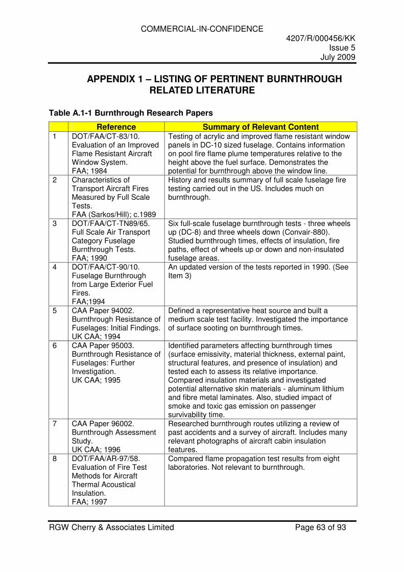
COMMERCIAL-IN-CONFIDENCE 4207/R/000456/KK
Issue 5 July 2009
RGW Cherry & Associates Limited Page 63 of 93
APPENDIX 1 – LISTING OF PERTINENT BURNTHROUGH RELATED LITERATURE
Table A.1-1 Burnthrough Research Papers
Reference Summary of Relevant Content 1 DOT/FAA/CT-83/10.
Evaluation of an Improved Flame Resistant Aircraft Window System. FAA; 1984
Testing of acrylic and improved flame resistant window panels in DC-10 sized fuselage. Contains information on pool fire flame plume temperatures relative to the height above the fuel surface. Demonstrates the potential for burnthrough above the window line.
2 Characteristics of Transport Aircraft Fires Measured by Full Scale Tests. FAA (Sarkos/Hill); c.1989
History and results summary of full scale fuselage fire testing carried out in the US. Includes much on burnthrough.
3 DOT/FAA/CT-TN89/65. Full Scale Air Transport Category Fuselage Burnthrough Tests. FAA; 1990
Six full-scale fuselage burnthrough tests - three wheels up (DC-8) and three wheels down (Convair-880). Studied burnthrough times, effects of insulation, fire paths, effect of wheels up or down and non-insulated fuselage areas.
4 DOT/FAA/CT-90/10. Fuselage Burnthrough from Large Exterior Fuel Fires. FAA;1994
An updated version of the tests reported in 1990. (See Item 3)
5 CAA Paper 94002. Burnthrough Resistance of Fuselages: Initial Findings. UK CAA; 1994
Defined a representative heat source and built a medium scale test facility. Investigated the importance of surface sooting on burnthrough times.
6 CAA Paper 95003. Burnthrough Resistance of Fuselages: Further Investigation. UK CAA; 1995
Identified parameters affecting burnthrough times (surface emissivity, material thickness, external paint, structural features, and presence of insulation) and tested each to assess its relative importance. Compared insulation materials and investigated potential alternative skin materials - aluminum lithium and fibre metal laminates. Also, studied impact of smoke and toxic gas emission on passenger survivability time.
7 CAA Paper 96002. Burnthrough Assessment Study. UK CAA; 1996
Researched burnthrough routes utilizing a review of past accidents and a survey of aircraft. Includes many relevant photographs of aircraft cabin insulation features.
8 DOT/FAA/AR-97/58. Evaluation of Fire Test Methods for Aircraft Thermal Acoustical Insulation. FAA; 1997
Compared flame propagation test results from eight laboratories. Not relevant to burnthrough.

COMMERCIAL-IN-CONFIDENCE 4207/R/000456/KK
Issue 5 July 2009
RGW Cherry & Associates Limited Page 64 of 93
Reference Summary of Relevant Content 9 DOT/FAA/AR-99/57. (CAA
Paper 99003). Fuselage Burnthrough Protection for Increased Postcrash Occupant Survivability: Safety Benefit Analysis Based on Past Accidents. FAA; 1999
Assessed the potential benefits, in terms of reduction of fatalities and injuries, resulting from improvements in cabin burnthrough resistance to ground pool fires.
10 DOT/FAA/AR-98/52. Full Scale Test Evaluation of Aircraft Fuel Fire Burnthrough Resistance Improvements. FAA; 1999
Full scale test rig developed. Twenty eight full scale tests conducted to determine the effectiveness of thermal-acoustic insulation improvements in preventing or delaying burnthrough. Showed that the method of attaching the insulation to the fuselage structure had a critical effect on the effectiveness of the insulation material. Oxidized Polyacrylonitrile Fibre (OPF) encased in a polyimide bagging material prevented burnthrough for over 8 minutes, in contrast with current insulation materials, which were shown to fail in as little as 2 minutes,
11 CAA Paper 99012. Investigation into the Effect of Corrosion Inhibiting Compound on Fuselage Burnthrough. UK CAA; 1999
Studied the effect on burnthrough times of corrosion inhibiting compounds applied on the inside of fuselages.
12 DOT/FAA/AR-99/44. Development of Improved Flammability Criteria for Aircraft Thermal Acoustic Insulation. FAA; 2000
New laboratory test developed for evaluating the burnthrough resistance of thermal acoustic insulation. The test method was based on full-scale tests in which a fuselage structure was subjected to jet fuel fires. Approximately 60 burnthrough tests were conducted on a variety of insulation materials. Insulation materials compliant with the new burnthrough test method will provide a minimum of 4 minutes of protection against a post-crash fuel fire. (Included flame propagation testing and development of Radiant Panel Test – not relevant to burnthrough)
13 Development of Improved Fire Test Criteria For Aircraft Thermal Acoustical Insulation. FAA; c.2000
Includes extensive burnthrough time and temperature data for numerous insulation materials.
14 CAA Paper 2001/1. Report on Fuselage Burnthrough Research Addressing Installation Aspects. UK CAA (Darchem Flare); 2001
Using the Darchem medium scale burnthrough test rig, the criticality of the installation aspects of thermal acoustic liners was investigated. This was carried out in support of the FAA NPRM.
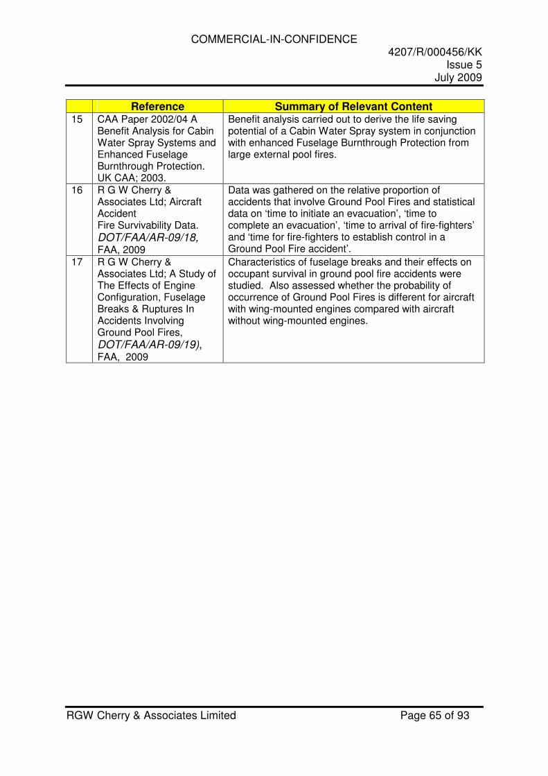
COMMERCIAL-IN-CONFIDENCE 4207/R/000456/KK
Issue 5 July 2009
RGW Cherry & Associates Limited Page 65 of 93
Reference Summary of Relevant Content 15 CAA Paper 2002/04 A
Benefit Analysis for Cabin Water Spray Systems and Enhanced Fuselage Burnthrough Protection. UK CAA; 2003.
Benefit analysis carried out to derive the life saving potential of a Cabin Water Spray system in conjunction with enhanced Fuselage Burnthrough Protection from large external pool fires.
16 R G W Cherry & Associates Ltd; Aircraft Accident Fire Survivability Data. DOT/FAA/AR-09/18, FAA, 2009
Data was gathered on the relative proportion of accidents that involve Ground Pool Fires and statistical data on ‘time to initiate an evacuation’, ‘time to complete an evacuation’, ‘time to arrival of fire-fighters’ and ‘time for fire-fighters to establish control in a Ground Pool Fire accident’.
17 R G W Cherry & Associates Ltd; A Study of The Effects of Engine Configuration, Fuselage Breaks & Ruptures In Accidents Involving Ground Pool Fires, DOT/FAA/AR-09/19), FAA, 2009
Characteristics of fuselage breaks and their effects on occupant survival in ground pool fire accidents were studied. Also assessed whether the probability of occurrence of Ground Pool Fires is different for aircraft with wing-mounted engines compared with aircraft without wing-mounted engines.
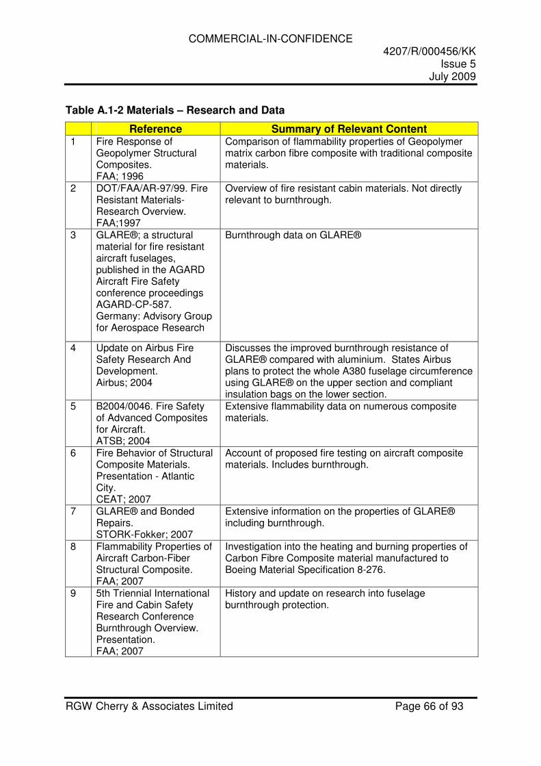
COMMERCIAL-IN-CONFIDENCE 4207/R/000456/KK
Issue 5 July 2009
RGW Cherry & Associates Limited Page 66 of 93
Table A.1-2 Materials – Research and Data
Reference Summary of Relevant Content 1 Fire Response of
Geopolymer Structural Composites. FAA; 1996
Comparison of flammability properties of Geopolymer matrix carbon fibre composite with traditional composite materials.
2 DOT/FAA/AR-97/99. Fire Resistant Materials-Research Overview. FAA;1997
Overview of fire resistant cabin materials. Not directly relevant to burnthrough.
3 GLARE®; a structural material for fire resistant aircraft fuselages, published in the AGARD Aircraft Fire Safety conference proceedings AGARD-CP-587. Germany: Advisory Group for Aerospace Research
Burnthrough data on GLARE®
4 Update on Airbus Fire Safety Research And Development. Airbus; 2004
Discusses the improved burnthrough resistance of GLARE® compared with aluminium. States Airbus plans to protect the whole A380 fuselage circumference using GLARE® on the upper section and compliant insulation bags on the lower section.
5 B2004/0046. Fire Safety of Advanced Composites for Aircraft. ATSB; 2004
Extensive flammability data on numerous composite materials.
6 Fire Behavior of Structural Composite Materials. Presentation - Atlantic City. CEAT; 2007
Account of proposed fire testing on aircraft composite materials. Includes burnthrough.
7 GLARE® and Bonded Repairs. STORK-Fokker; 2007
Extensive information on the properties of GLARE® including burnthrough.
8 Flammability Properties of Aircraft Carbon-Fiber Structural Composite. FAA; 2007
Investigation into the heating and burning properties of Carbon Fibre Composite material manufactured to Boeing Material Specification 8-276.
9 5th Triennial International Fire and Cabin Safety Research Conference Burnthrough Overview. Presentation. FAA; 2007
History and update on research into fuselage burnthrough protection.
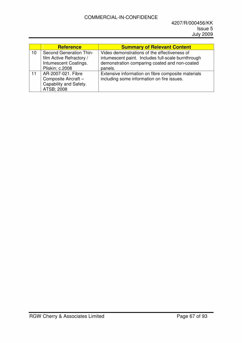
COMMERCIAL-IN-CONFIDENCE 4207/R/000456/KK
Issue 5 July 2009
RGW Cherry & Associates Limited Page 67 of 93
Reference Summary of Relevant Content 10 Second Generation Thin-
film Active Refractory / Intumescent Coatings. Pliskin; c.2008
Video demonstrations of the effectiveness of intumescent paint. Includes full-scale burnthrough demonstration comparing coated and non-coated panels.
11 AR-2007-021. Fibre Composite Aircraft – Capability and Safety. ATSB; 2008
Extensive information on fibre composite materials including some information on fire issues.
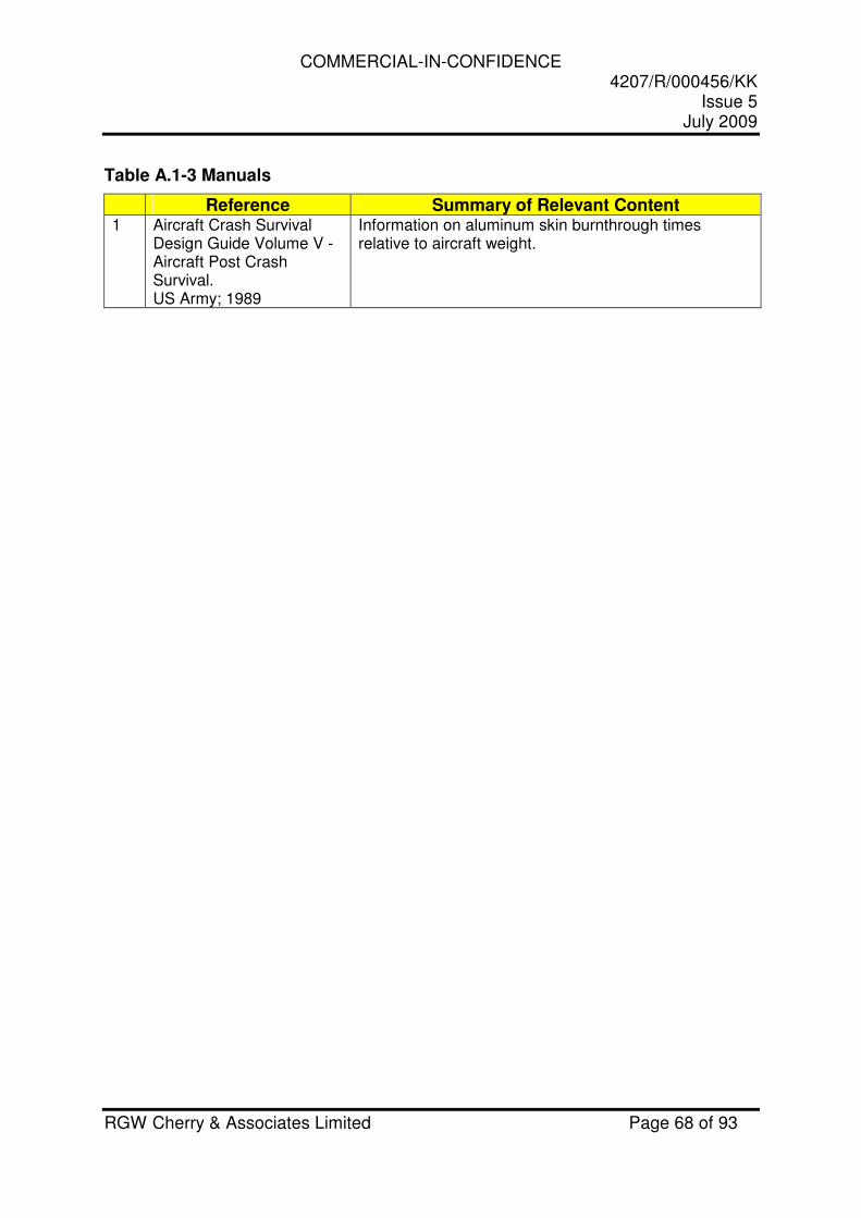
COMMERCIAL-IN-CONFIDENCE 4207/R/000456/KK
Issue 5 July 2009
RGW Cherry & Associates Limited Page 68 of 93
Table A.1-3 Manuals
Reference Summary of Relevant Content 1 Aircraft Crash Survival
Design Guide Volume V - Aircraft Post Crash Survival. US Army; 1989
Information on aluminum skin burnthrough times relative to aircraft weight.
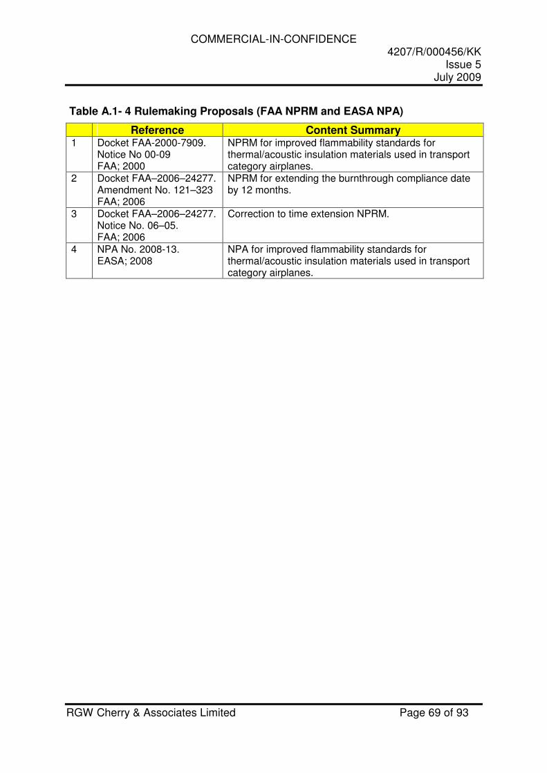
COMMERCIAL-IN-CONFIDENCE 4207/R/000456/KK
Issue 5 July 2009
RGW Cherry & Associates Limited Page 69 of 93
Table A.1- 4 Rulemaking Proposals (FAA NPRM and EASA NPA)
Reference Content Summary 1 Docket FAA-2000-7909.
Notice No 00-09 FAA; 2000
NPRM for improved flammability standards for thermal/acoustic insulation materials used in transport category airplanes.
2 Docket FAA–2006–24277. Amendment No. 121–323 FAA; 2006
NPRM for extending the burnthrough compliance date by 12 months.
3 Docket FAA–2006–24277. Notice No. 06–05. FAA; 2006
Correction to time extension NPRM.
4 NPA No. 2008-13. EASA; 2008
NPA for improved flammability standards for thermal/acoustic insulation materials used in transport category airplanes.
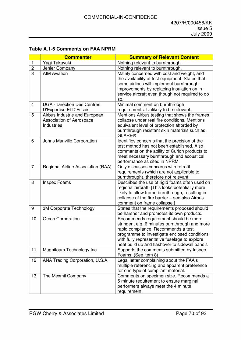
COMMERCIAL-IN-CONFIDENCE 4207/R/000456/KK
Issue 5 July 2009
RGW Cherry & Associates Limited Page 70 of 93
Table A.1-5 Comments on FAA NPRM
Commenter Summary of Relevant Content 1 Yagi Takayuki Nothing relevant to burnthrough. 2 Jehier Company Nothing relevant to burnthrough. 3 AIM Aviation Mainly concerned with cost and weight, and
the availability of test equipment. States that some airlines will implement burnthrough improvements by replacing insulation on in-service aircraft even though not required to do so.
4 DGA - Direction Des Centres D'Expertise Et D'Essais
Minimal comment on burnthrough requirements. Unlikely to be relevant.
5 Airbus Industrie and European Association of Aerospace Industries
Mentions Airbus testing that shows the frames collapse under real fire conditions. Mentions equivalent level of protection afforded by burnthrough resistant skin materials such as GLARE®
6 Johns Manville Corporation Identifies concerns that the precision of the test method has not been established. Also comments on the ability of Curlon products to meet necessary burnthrough and acoustical performance as cited in NPRM.
7 Regional Airline Association (RAA) Only discusses concerns with retrofit requirements (which are not applicable to burnthrough), therefore not relevant.
8 Inspec Foams Describes the use of rigid foams often used on regional aircraft. [This looks potentially more likely to allow frame burnthrough, resulting in collapse of the fire barrier – see also Airbus comment on frame collapse.]
9 3M Corporate Technology States that the requirements proposed should be harsher and promotes its own products.
10 Orcon Corporation Recommends requirement should be more stringent e.g. 6 minutes burnthrough and more rapid compliance. Recommends a test programme to investigate enclosed conditions with fully representative fuselage to explore heat build up and flashover to sidewall panels
11 Magnifoam Technology Inc. Supports the comments submitted by Inspec Foams. (See item 8)
12 ANA Trading Corporation, U.S.A. Legal letter complaining about the FAA’s multiple referencing and apparent preference for one type of compliant material.
13 The Mexmil Company Comments on specimen size. Recommends a 5 minute requirement to ensure marginal performers always meet the 4 minute requirement.
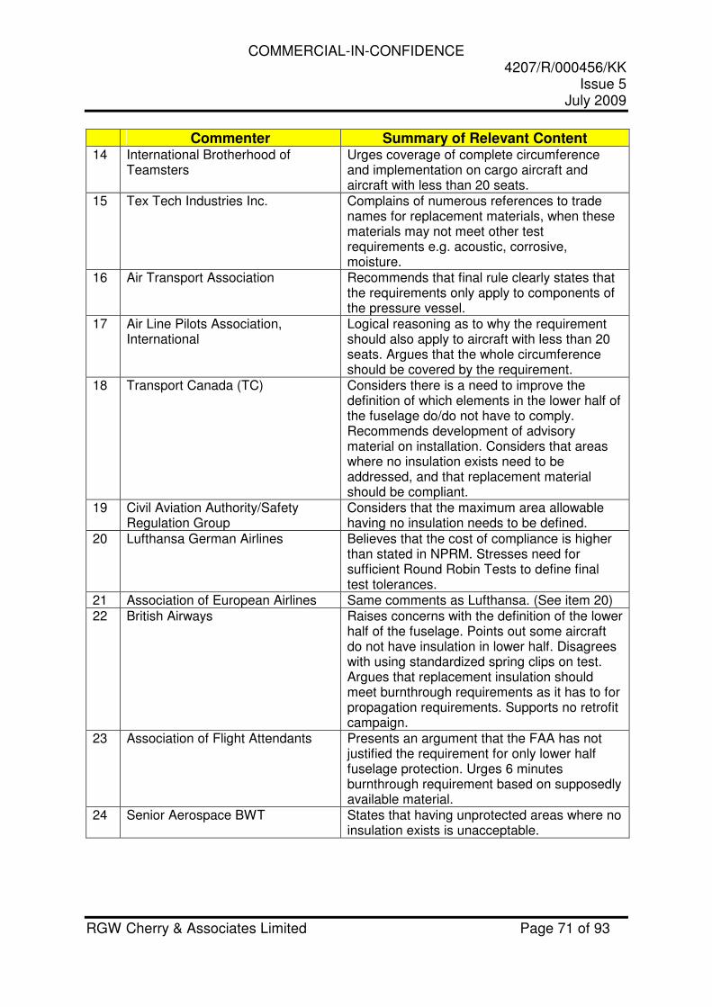
COMMERCIAL-IN-CONFIDENCE 4207/R/000456/KK
Issue 5 July 2009
RGW Cherry & Associates Limited Page 71 of 93
Commenter Summary of Relevant Content 14 International Brotherhood of
Teamsters Urges coverage of complete circumference and implementation on cargo aircraft and aircraft with less than 20 seats.
15 Tex Tech Industries Inc. Complains of numerous references to trade names for replacement materials, when these materials may not meet other test requirements e.g. acoustic, corrosive, moisture.
16 Air Transport Association Recommends that final rule clearly states that the requirements only apply to components of the pressure vessel.
17 Air Line Pilots Association, International
Logical reasoning as to why the requirement should also apply to aircraft with less than 20 seats. Argues that the whole circumference should be covered by the requirement.
18 Transport Canada (TC) Considers there is a need to improve the definition of which elements in the lower half of the fuselage do/do not have to comply. Recommends development of advisory material on installation. Considers that areas where no insulation exists need to be addressed, and that replacement material should be compliant.
19 Civil Aviation Authority/Safety Regulation Group
Considers that the maximum area allowable having no insulation needs to be defined.
20 Lufthansa German Airlines Believes that the cost of compliance is higher than stated in NPRM. Stresses need for sufficient Round Robin Tests to define final test tolerances.
21 Association of European Airlines Same comments as Lufthansa. (See item 20) 22 British Airways Raises concerns with the definition of the lower
half of the fuselage. Points out some aircraft do not have insulation in lower half. Disagrees with using standardized spring clips on test. Argues that replacement insulation should meet burnthrough requirements as it has to for propagation requirements. Supports no retrofit campaign.
23 Association of Flight Attendants Presents an argument that the FAA has not justified the requirement for only lower half fuselage protection. Urges 6 minutes burnthrough requirement based on supposedly available material.
24 Senior Aerospace BWT States that having unprotected areas where no insulation exists is unacceptable.
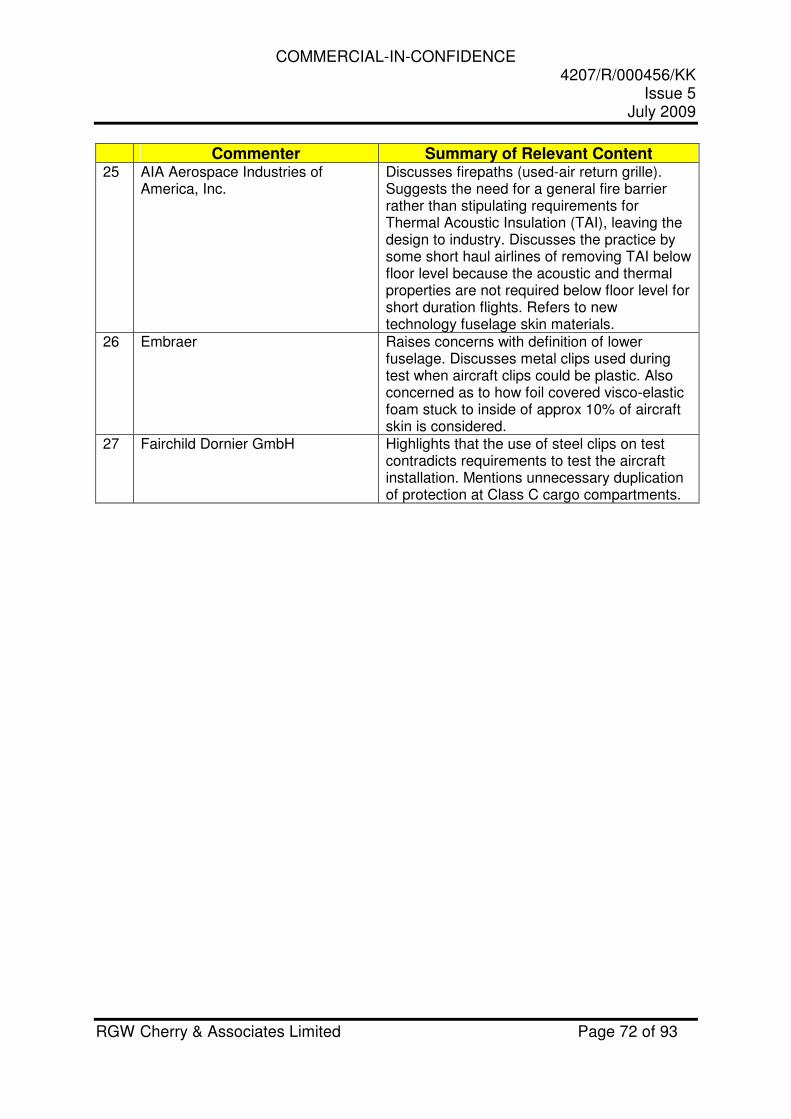
COMMERCIAL-IN-CONFIDENCE 4207/R/000456/KK
Issue 5 July 2009
RGW Cherry & Associates Limited Page 72 of 93
Commenter Summary of Relevant Content 25 AIA Aerospace Industries of
America, Inc. Discusses firepaths (used-air return grille). Suggests the need for a general fire barrier rather than stipulating requirements for Thermal Acoustic Insulation (TAI), leaving the design to industry. Discusses the practice by some short haul airlines of removing TAI below floor level because the acoustic and thermal properties are not required below floor level for short duration flights. Refers to new technology fuselage skin materials.
26 Embraer Raises concerns with definition of lower fuselage. Discusses metal clips used during test when aircraft clips could be plastic. Also concerned as to how foil covered visco-elastic foam stuck to inside of approx 10% of aircraft skin is considered.
27 Fairchild Dornier GmbH Highlights that the use of steel clips on test contradicts requirements to test the aircraft installation. Mentions unnecessary duplication of protection at Class C cargo compartments.

COMMERCIAL-IN-CONFIDENCE 4207/R/000456/KK
Issue 5 July 2009
RGW Cherry & Associates Limited Page 73 of 93
Table A.1-6 Comments on FAA Time Extension NPRM
Commenter Summary of Relevant Content 1 Boeing Supports the proposed one year extension
with reservations about availability of TAI materials and test apparatus.
2 Air Line Pilots Association, International
Acknowledges the one year delay seems reasonable but reiterates the need for upper half coverage and inclusion on aircraft with less than 20 seats.
3 Association of European Airlines Supports Airbus comments. (See item 4) 4 Airbus Argues case for 2 years extension rather than
1 year based on problems with test apparatus. 5 COGEBI States the company has a solution that meets
the requirements therefore there is no need for time extension.
6 Daher-Lhotellier Same comments as COGEBI. (See item 5) 7 AIA Aerospace Industries of
America, Inc. Logical argument for time extension to be 2 years instead of 1 year based on the burner issues and availability of compliant materials that meet cost and weight constraints.
8 Bombardier Aerospace
Supports 1 year time extension, citing burner issues, aircraft design effort and non-availability of compliant materials. Implies Bombardier is considering using cabin floor as the fire barrier under Equivalent Level of Safety instead of insulation bags, and that this requires extra design effort and development of a suitable test frame.
9 Air Transport Association Supports the proposed one year extension.
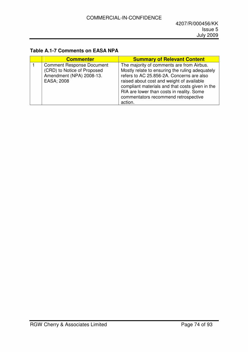
COMMERCIAL-IN-CONFIDENCE 4207/R/000456/KK
Issue 5 July 2009
RGW Cherry & Associates Limited Page 74 of 93
Table A.1-7 Comments on EASA NPA
Commenter Summary of Relevant Content 1 Comment Response Document
(CRD) to Notice of Proposed Amendment (NPA) 2008-13. EASA; 2008
The majority of comments are from Airbus. Mostly relate to ensuring the ruling adequately refers to AC 25.856-2A. Concerns are also raised about cost and weight of available compliant materials and that costs given in the RIA are lower than costs in reality. Some commentators recommend retrospective action.
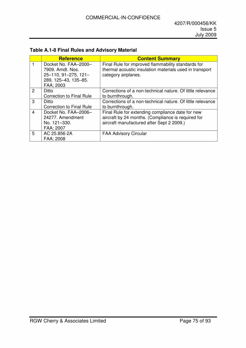
COMMERCIAL-IN-CONFIDENCE 4207/R/000456/KK
Issue 5 July 2009
RGW Cherry & Associates Limited Page 75 of 93
Table A.1-8 Final Rules and Advisory Material
Reference Content Summary 1 Docket No. FAA–2000–
7909. Amdt. Nos. 25–110, 91–275, 121–289, 125–43, 135–85. FAA; 2003
Final Rule for improved flammability standards for thermal acoustic insulation materials used in transport category airplanes.
2 Ditto Correction to Final Rule
Corrections of a non-technical nature. Of little relevance to burnthrough.
3 Ditto Correction to Final Rule
Corrections of a non-technical nature. Of little relevance to burnthrough.
4 Docket No. FAA–2006–24277. Amendment No. 121–330. FAA; 2007
Final Rule for extending compliance date for new aircraft by 24 months. (Compliance is required for aircraft manufactured after Sept 2 2009.)
5 AC 25.856-2A FAA; 2008
FAA Advisory Circular
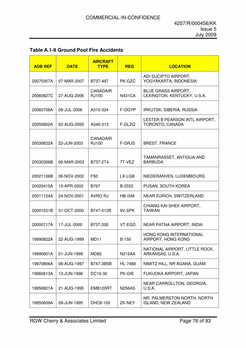
COMMERCIAL-IN-CONFIDENCE 4207/R/000456/KK
Issue 5 July 2009
RGW Cherry & Associates Limited Page 76 of 93
Table A.1-9 Ground Pool Fire Accidents
ADB REF DATE AIRCRAFT
TYPE REG LOCATION
20070307A 07-MAR-2007 B737-497 PK-GZC ADI SUCIPTO AIRPORT, YOGYAKARTA, INDONESIA
20060827C 27-AUG-2006 CANADAIR RJ100 N431CA
BLUE GRASS AIRPORT, LEXINGTON, KENTUCKY, U.S.A.
20060708A 08-JUL-2006 A310-324 F-OGYP IRKUTSK, SIBERIA, RUSSIA
20050802A 02-AUG-2005 A340-313 F-GLZQ LESTER B PEARSON INTL AIRPORT, TORONTO, CANADA
20030622A 22-JUN-2003 CANADAIR RJ100 F-GRJS BREST, FRANCE
20030306B 06-MAR-2003 B737-2T4 7T-VEZ TAMANRASSET, ANTIGUA AND BARBUDA
20021106B 06-NOV-2002 F50 LX-LGB NIEDERANVEN, LUXEMBOURG
20020415A 15-APR-2002 B767 B-2552 PUSAN, SOUTH KOREA
20011124A 24-NOV-2001 AVRO RJ HB-IXM NEAR ZURICH, SWITZERLAND
20001031B 31-OCT-2000 B747-412B 9V-SPK CHIANG KAI-SHEK AIRPORT, TAIWAN
20000717A 17-JUL-2000 B737-200 VT-EGD NEAR PATNA AIRPORT, INDIA
19990822A 22-AUG-1999 MD11 B-150 HONG KONG INTERNATIONAL AIRPORT, HONG KONG
19990601A 01-JUN-1999 MD82 N215AA NATIONAL AIRPORT, LITTLE ROCK, ARKANSAS, U.S.A.
19970806A 06-AUG-1997 B747-3B5B HL-7468 NIMITZ HILL, NR AGANA, GUAM
19960613A 13-JUN-1996 DC10-30 PK-GIE FUKUOKA AIRPORT, JAPAN
19950821A 21-AUG-1995 EMB120RT N256AS NEAR CARROLLTON, GEORGIA, U.S.A.
19950609A 09-JUN-1995 DHC8-100 ZK-NEY NR. PALMERSTON NORTH, NORTH ISLAND, NEW ZEALAND
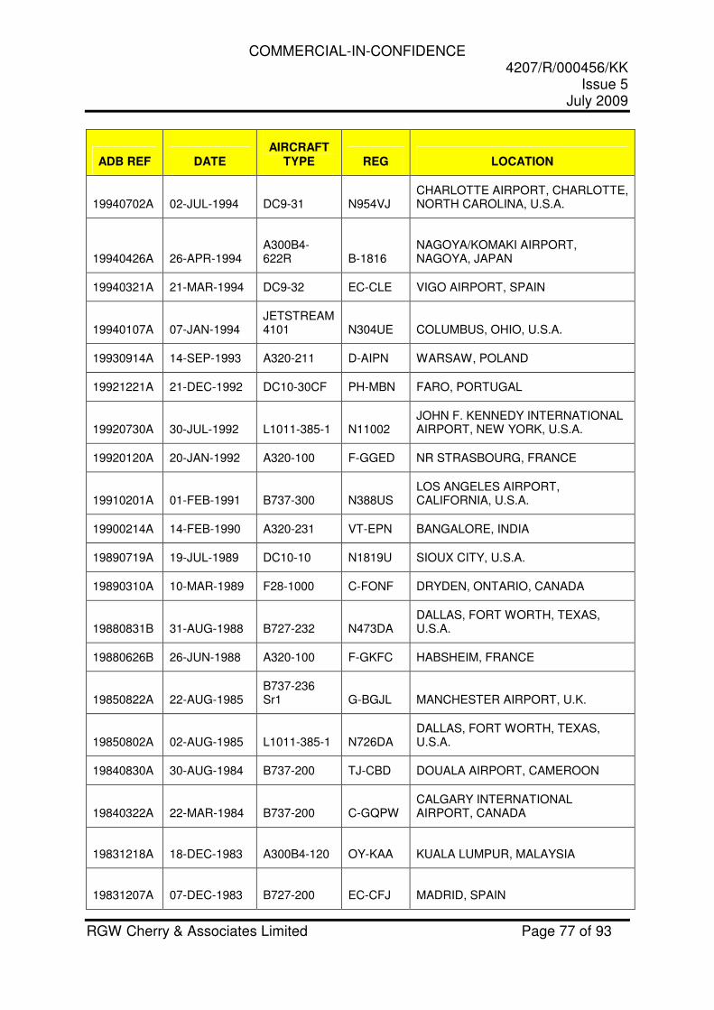
COMMERCIAL-IN-CONFIDENCE 4207/R/000456/KK
Issue 5 July 2009
RGW Cherry & Associates Limited Page 77 of 93
ADB REF DATE AIRCRAFT
TYPE REG LOCATION
19940702A 02-JUL-1994 DC9-31 N954VJ CHARLOTTE AIRPORT, CHARLOTTE, NORTH CAROLINA, U.S.A.
19940426A 26-APR-1994 A300B4-622R B-1816
NAGOYA/KOMAKI AIRPORT, NAGOYA, JAPAN
19940321A 21-MAR-1994 DC9-32 EC-CLE VIGO AIRPORT, SPAIN
19940107A 07-JAN-1994 JETSTREAM 4101 N304UE COLUMBUS, OHIO, U.S.A.
19930914A 14-SEP-1993 A320-211 D-AIPN WARSAW, POLAND
19921221A 21-DEC-1992 DC10-30CF PH-MBN FARO, PORTUGAL
19920730A 30-JUL-1992 L1011-385-1 N11002 JOHN F. KENNEDY INTERNATIONAL AIRPORT, NEW YORK, U.S.A.
19920120A 20-JAN-1992 A320-100 F-GGED NR STRASBOURG, FRANCE
19910201A 01-FEB-1991 B737-300 N388US LOS ANGELES AIRPORT, CALIFORNIA, U.S.A.
19900214A 14-FEB-1990 A320-231 VT-EPN BANGALORE, INDIA
19890719A 19-JUL-1989 DC10-10 N1819U SIOUX CITY, U.S.A.
19890310A 10-MAR-1989 F28-1000 C-FONF DRYDEN, ONTARIO, CANADA
19880831B 31-AUG-1988 B727-232 N473DA DALLAS, FORT WORTH, TEXAS, U.S.A.
19880626B 26-JUN-1988 A320-100 F-GKFC HABSHEIM, FRANCE
19850822A 22-AUG-1985 B737-236 Sr1 G-BGJL MANCHESTER AIRPORT, U.K.
19850802A 02-AUG-1985 L1011-385-1 N726DA DALLAS, FORT WORTH, TEXAS, U.S.A.
19840830A 30-AUG-1984 B737-200 TJ-CBD DOUALA AIRPORT, CAMEROON
19840322A 22-MAR-1984 B737-200 C-GQPW CALGARY INTERNATIONAL AIRPORT, CANADA
19831218A 18-DEC-1983 A300B4-120 OY-KAA KUALA LUMPUR, MALAYSIA
19831207A 07-DEC-1983 B727-200 EC-CFJ MADRID, SPAIN
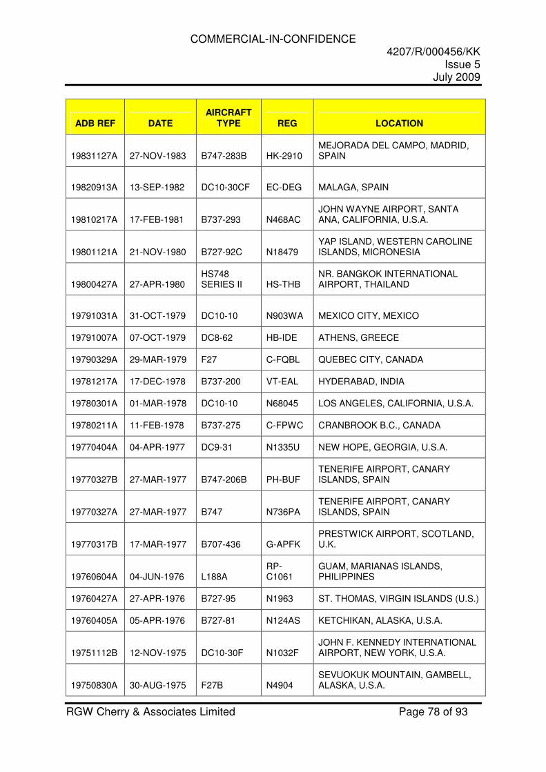
COMMERCIAL-IN-CONFIDENCE 4207/R/000456/KK
Issue 5 July 2009
RGW Cherry & Associates Limited Page 78 of 93
ADB REF DATE AIRCRAFT
TYPE REG LOCATION
19831127A 27-NOV-1983 B747-283B HK-2910 MEJORADA DEL CAMPO, MADRID, SPAIN
19820913A 13-SEP-1982 DC10-30CF EC-DEG MALAGA, SPAIN
19810217A 17-FEB-1981 B737-293 N468AC JOHN WAYNE AIRPORT, SANTA ANA, CALIFORNIA, U.S.A.
19801121A 21-NOV-1980 B727-92C N18479 YAP ISLAND, WESTERN CAROLINE ISLANDS, MICRONESIA
19800427A 27-APR-1980 HS748 SERIES II HS-THB
NR. BANGKOK INTERNATIONAL AIRPORT, THAILAND
19791031A 31-OCT-1979 DC10-10 N903WA MEXICO CITY, MEXICO
19791007A 07-OCT-1979 DC8-62 HB-IDE ATHENS, GREECE
19790329A 29-MAR-1979 F27 C-FQBL QUEBEC CITY, CANADA
19781217A 17-DEC-1978 B737-200 VT-EAL HYDERABAD, INDIA
19780301A 01-MAR-1978 DC10-10 N68045 LOS ANGELES, CALIFORNIA, U.S.A.
19780211A 11-FEB-1978 B737-275 C-FPWC CRANBROOK B.C., CANADA
19770404A 04-APR-1977 DC9-31 N1335U NEW HOPE, GEORGIA, U.S.A.
19770327B 27-MAR-1977 B747-206B PH-BUF TENERIFE AIRPORT, CANARY ISLANDS, SPAIN
19770327A 27-MAR-1977 B747 N736PA TENERIFE AIRPORT, CANARY ISLANDS, SPAIN
19770317B 17-MAR-1977 B707-436 G-APFK PRESTWICK AIRPORT, SCOTLAND, U.K.
19760604A 04-JUN-1976 L188A RP-C1061
GUAM, MARIANAS ISLANDS, PHILIPPINES
19760427A 27-APR-1976 B727-95 N1963 ST. THOMAS, VIRGIN ISLANDS (U.S.)
19760405A 05-APR-1976 B727-81 N124AS KETCHIKAN, ALASKA, U.S.A.
19751112B 12-NOV-1975 DC10-30F N1032F JOHN F. KENNEDY INTERNATIONAL AIRPORT, NEW YORK, U.S.A.
19750830A 30-AUG-1975 F27B N4904 SEVUOKUK MOUNTAIN, GAMBELL, ALASKA, U.S.A.
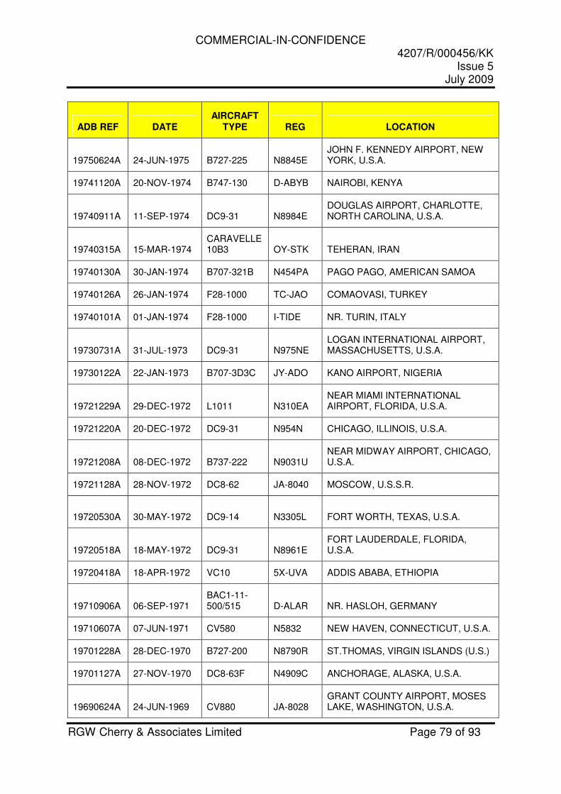
COMMERCIAL-IN-CONFIDENCE 4207/R/000456/KK
Issue 5 July 2009
RGW Cherry & Associates Limited Page 79 of 93
ADB REF DATE AIRCRAFT
TYPE REG LOCATION
19750624A 24-JUN-1975 B727-225 N8845E JOHN F. KENNEDY AIRPORT, NEW YORK, U.S.A.
19741120A 20-NOV-1974 B747-130 D-ABYB NAIROBI, KENYA
19740911A 11-SEP-1974 DC9-31 N8984E DOUGLAS AIRPORT, CHARLOTTE, NORTH CAROLINA, U.S.A.
19740315A 15-MAR-1974 CARAVELLE 10B3 OY-STK TEHERAN, IRAN
19740130A 30-JAN-1974 B707-321B N454PA PAGO PAGO, AMERICAN SAMOA
19740126A 26-JAN-1974 F28-1000 TC-JAO COMAOVASI, TURKEY
19740101A 01-JAN-1974 F28-1000 I-TIDE NR. TURIN, ITALY
19730731A 31-JUL-1973 DC9-31 N975NE LOGAN INTERNATIONAL AIRPORT, MASSACHUSETTS, U.S.A.
19730122A 22-JAN-1973 B707-3D3C JY-ADO KANO AIRPORT, NIGERIA
19721229A 29-DEC-1972 L1011 N310EA NEAR MIAMI INTERNATIONAL AIRPORT, FLORIDA, U.S.A.
19721220A 20-DEC-1972 DC9-31 N954N CHICAGO, ILLINOIS, U.S.A.
19721208A 08-DEC-1972 B737-222 N9031U NEAR MIDWAY AIRPORT, CHICAGO, U.S.A.
19721128A 28-NOV-1972 DC8-62 JA-8040 MOSCOW, U.S.S.R.
19720530A 30-MAY-1972 DC9-14 N3305L FORT WORTH, TEXAS, U.S.A.
19720518A 18-MAY-1972 DC9-31 N8961E FORT LAUDERDALE, FLORIDA, U.S.A.
19720418A 18-APR-1972 VC10 5X-UVA ADDIS ABABA, ETHIOPIA
19710906A 06-SEP-1971 BAC1-11-500/515 D-ALAR NR. HASLOH, GERMANY
19710607A 07-JUN-1971 CV580 N5832 NEW HAVEN, CONNECTICUT, U.S.A.
19701228A 28-DEC-1970 B727-200 N8790R ST.THOMAS, VIRGIN ISLANDS (U.S.)
19701127A 27-NOV-1970 DC8-63F N4909C ANCHORAGE, ALASKA, U.S.A.
19690624A 24-JUN-1969 CV880 JA-8028 GRANT COUNTY AIRPORT, MOSES LAKE, WASHINGTON, U.S.A.
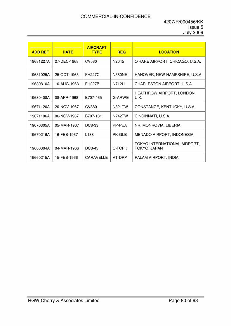
COMMERCIAL-IN-CONFIDENCE 4207/R/000456/KK
Issue 5 July 2009
RGW Cherry & Associates Limited Page 80 of 93
ADB REF DATE AIRCRAFT
TYPE REG LOCATION
19681227A 27-DEC-1968 CV580 N2045 O'HARE AIRPORT, CHICAGO, U.S.A.
19681025A 25-OCT-1968 FH227C N380NE HANOVER, NEW HAMPSHIRE, U.S.A.
19680810A 10-AUG-1968 FH227B N712U CHARLESTON AIRPORT, U.S.A.
19680408A 08-APR-1968 B707-465 G-ARWE HEATHROW AIRPORT, LONDON, U.K.
19671120A 20-NOV-1967 CV880 N821TW CONSTANCE, KENTUCKY, U.S.A.
19671106A 06-NOV-1967 B707-131 N742TW CINCINNATI, U.S.A.
19670305A 05-MAR-1967 DC8-33 PP-PEA NR. MONROVIA, LIBERIA
19670216A 16-FEB-1967 L188 PK-GLB MENADO AIRPORT, INDONESIA
19660304A 04-MAR-1966 DC8-43 C-FCPK TOKYO INTERNATIONAL AIRPORT, TOKYO, JAPAN
19660215A 15-FEB-1966 CARAVELLE VT-DPP PALAM AIRPORT, INDIA
COMMERCIAL-IN-CONFIDENCE 4207/R/000456/KK
Issue 5 July 2009
RGW Cherry & Associates Limited Page 81 of 93
Table A.1-10 Miscellaneous
Reference Summary of Relevant Content 1 Burnthrough Update.
International Aircraft Materials Fire Test Working Group Meeting - Atlantic City; 2008
An update on the burnthrough test burner.

COMMERCIAL-IN-CONFIDENCE 4207/R/000456/KK
Issue 5 July 2009
RGW Cherry & Associates Limited Page 82 of 93
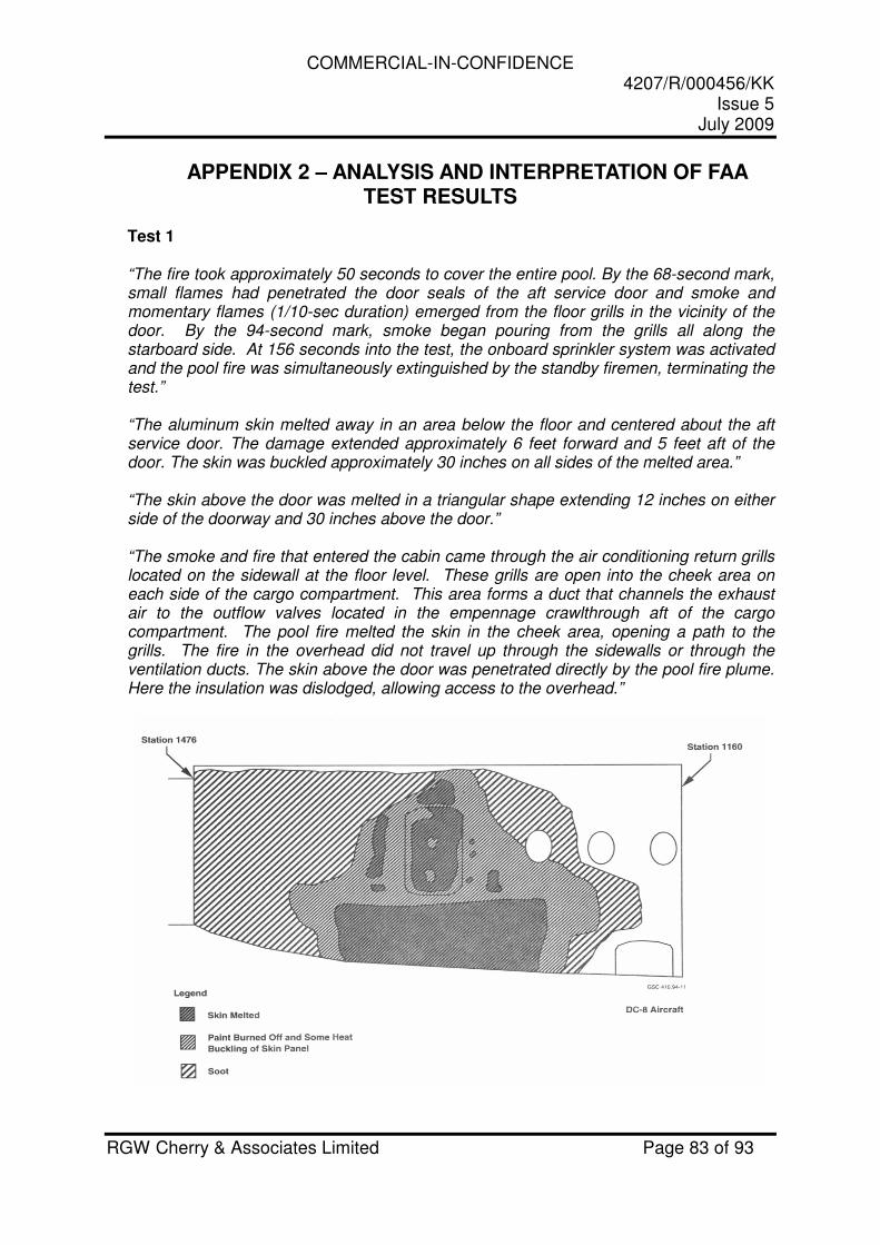
COMMERCIAL-IN-CONFIDENCE 4207/R/000456/KK
Issue 5 July 2009
RGW Cherry & Associates Limited Page 83 of 93
APPENDIX 2 – ANALYSIS AND INTERPRETATION OF FAA TEST RESULTS
Test 1 “The fire took approximately 50 seconds to cover the entire pool. By the 68-second mark, small flames had penetrated the door seals of the aft service door and smoke and momentary flames (1/10-sec duration) emerged from the floor grills in the vicinity of the door. By the 94-second mark, smoke began pouring from the grills all along the starboard side. At 156 seconds into the test, the onboard sprinkler system was activated and the pool fire was simultaneously extinguished by the standby firemen, terminating the test.” “The aluminum skin melted away in an area below the floor and centered about the aft service door. The damage extended approximately 6 feet forward and 5 feet aft of the door. The skin was buckled approximately 30 inches on all sides of the melted area.” “The skin above the door was melted in a triangular shape extending 12 inches on either side of the doorway and 30 inches above the door.” “The smoke and fire that entered the cabin came through the air conditioning return grills located on the sidewall at the floor level. These grills are open into the cheek area on each side of the cargo compartment. This area forms a duct that channels the exhaust air to the outflow valves located in the empennage crawlthrough aft of the cargo compartment. The pool fire melted the skin in the cheek area, opening a path to the grills. The fire in the overhead did not travel up through the sidewalls or through the ventilation ducts. The skin above the door was penetrated directly by the pool fire plume. Here the insulation was dislodged, allowing access to the overhead.”
COMMERCIAL-IN-CONFIDENCE 4207/R/000456/KK
Issue 5 July 2009
RGW Cherry & Associates Limited Page 84 of 93
Observation 1.1 The elapsed time from when the pool fire had fully established to when smoke began pouring from the floor grills was 44 seconds. In this time the lower fuselage skin had melted in the cheek area. Test 1 indicates the capability of a fuel fire to melt the lower fuselage skin in around 44 seconds. Observation 1.2 The elapsed time from when the pool fire had fully established to when extinguishing commenced was 1 minute and 46 seconds. In this time the skin above the door had melted. Test 1 indicates the capability of a fuel fire to melt the upper fuselage skin within 1 minute and 46 seconds.
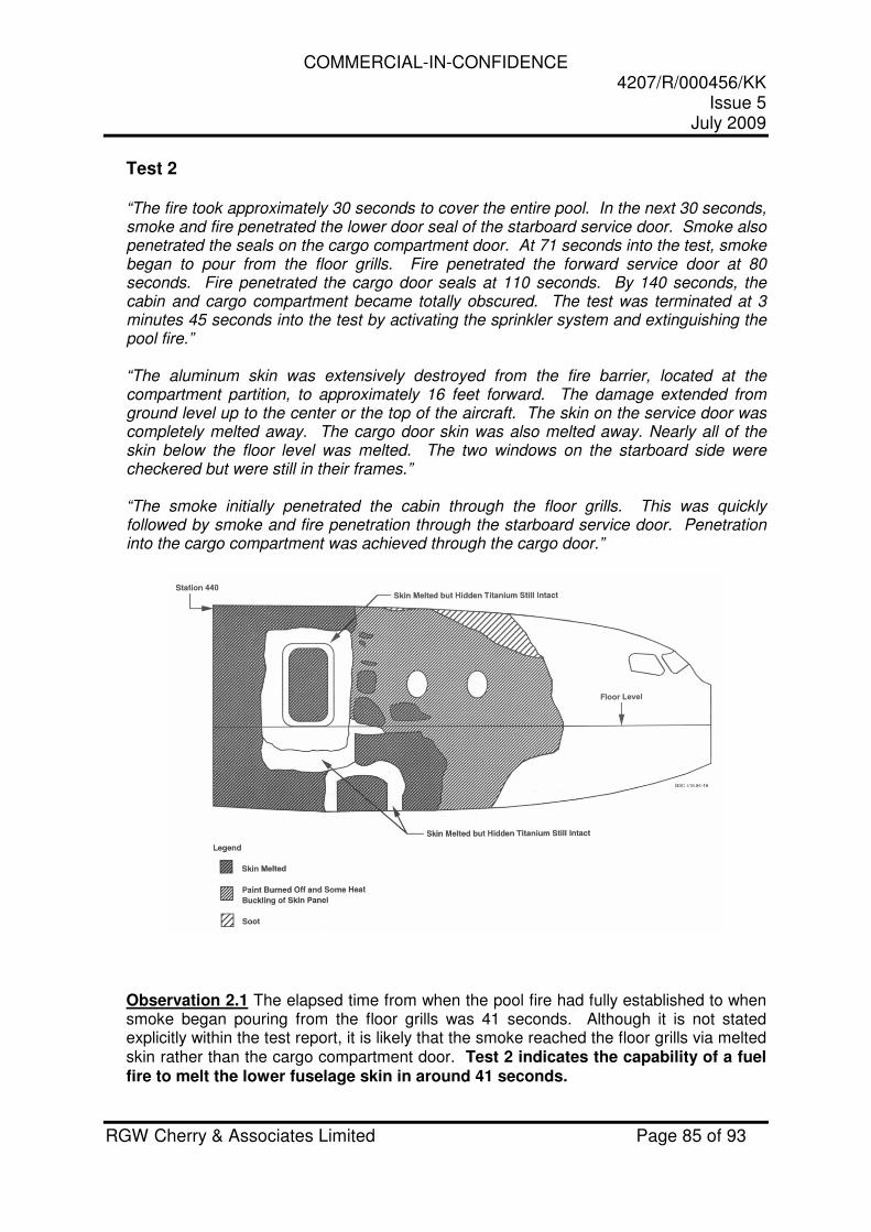
COMMERCIAL-IN-CONFIDENCE 4207/R/000456/KK
Issue 5 July 2009
RGW Cherry & Associates Limited Page 85 of 93
Test 2 “The fire took approximately 30 seconds to cover the entire pool. In the next 30 seconds, smoke and fire penetrated the lower door seal of the starboard service door. Smoke also penetrated the seals on the cargo compartment door. At 71 seconds into the test, smoke began to pour from the floor grills. Fire penetrated the forward service door at 80 seconds. Fire penetrated the cargo door seals at 110 seconds. By 140 seconds, the cabin and cargo compartment became totally obscured. The test was terminated at 3 minutes 45 seconds into the test by activating the sprinkler system and extinguishing the pool fire.” “The aluminum skin was extensively destroyed from the fire barrier, located at the compartment partition, to approximately 16 feet forward. The damage extended from ground level up to the center or the top of the aircraft. The skin on the service door was completely melted away. The cargo door skin was also melted away. Nearly all of the skin below the floor level was melted. The two windows on the starboard side were checkered but were still in their frames.” “The smoke initially penetrated the cabin through the floor grills. This was quickly followed by smoke and fire penetration through the starboard service door. Penetration into the cargo compartment was achieved through the cargo door.”
Observation 2.1 The elapsed time from when the pool fire had fully established to when smoke began pouring from the floor grills was 41 seconds. Although it is not stated explicitly within the test report, it is likely that the smoke reached the floor grills via melted skin rather than the cargo compartment door. Test 2 indicates the capability of a fuel fire to melt the lower fuselage skin in around 41 seconds.
COMMERCIAL-IN-CONFIDENCE 4207/R/000456/KK
Issue 5 July 2009
RGW Cherry & Associates Limited Page 86 of 93
Observation 2.2 The elapsed time from when the pool fire had fully established to when extinguishing commenced was 3 minutes and 15 seconds. In this time, the skin damage extended from ground level up to the centre or the top of the aircraft. Test 2 indicates the capability of a fuel fire to melt the upper fuselage skin within 3 minutes and 15 seconds.
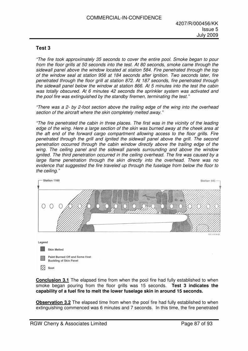
COMMERCIAL-IN-CONFIDENCE 4207/R/000456/KK
Issue 5 July 2009
RGW Cherry & Associates Limited Page 87 of 93
Test 3 “The fire took approximately 35 seconds to cover the entire pool. Smoke began to pour from the floor grills at 50 seconds into the test. At 80 seconds, smoke came through the sidewall panel above the window located at station 584. Fire penetrated through the top of the window seal at station 956 at 184 seconds after ignition. Two seconds later, fire penetrated through the floor grill at station 872. At 187 seconds, fire penetrated through the sidewall panel below the window at station 866. At 5 minutes into the test the cabin was totally obscured. At 6 minutes 42 seconds the sprinkler system was activated and the pool fire was extinguished by the standby firemen, terminating the test.” “There was a 2- by 2-foot section above the trailing edge of the wing into the overhead section of the aircraft where the skin completely melted away.” “The fire penetrated the cabin in three places. The first was in the vicinity of the leading edge of the wing. Here a large section of the skin was burned away at the cheek area at the aft end of the forward cargo compartment allowing access to the floor grills. Fire penetrated through the grill and ignited the sidewall panel above the grill. The second penetration occurred through the cabin window directly above the trailing edge of the wing. The ceiling panel and the sidewall panels surrounding and above the window ignited. The third penetration occurred in the ceiling overhead. The fire was caused by a large flame penetration through the skin directly into the overhead. There was no evidence that suggested the fire traveled up through the fuselage from below the floor to the ceiling.”
Conclusion 3.1 The elapsed time from when the pool fire had fully established to when smoke began pouring from the floor grills was 15 seconds. Test 3 indicates the capability of a fuel fire to melt the lower fuselage skin in around 15 seconds.
Observation 3.2 The elapsed time from when the pool fire had fully established to when extinguishing commenced was 6 minutes and 7 seconds. In this time, the fire penetrated
COMMERCIAL-IN-CONFIDENCE 4207/R/000456/KK
Issue 5 July 2009
RGW Cherry & Associates Limited Page 88 of 93
through the skin directly into the overhead. Test 3 indicates the capability of a fuel fire to melt the upper fuselage skin within 6 minutes and 7 seconds.
Observation 3.3 The elapsed time from when the pool fire had fully established to when fire penetrated through the top of the window seal at station 956 was 2 minutes 29 seconds. Test 3 indicates the capability of a fuel fire to penetrate past a window seal in 2 minutes 29 seconds.
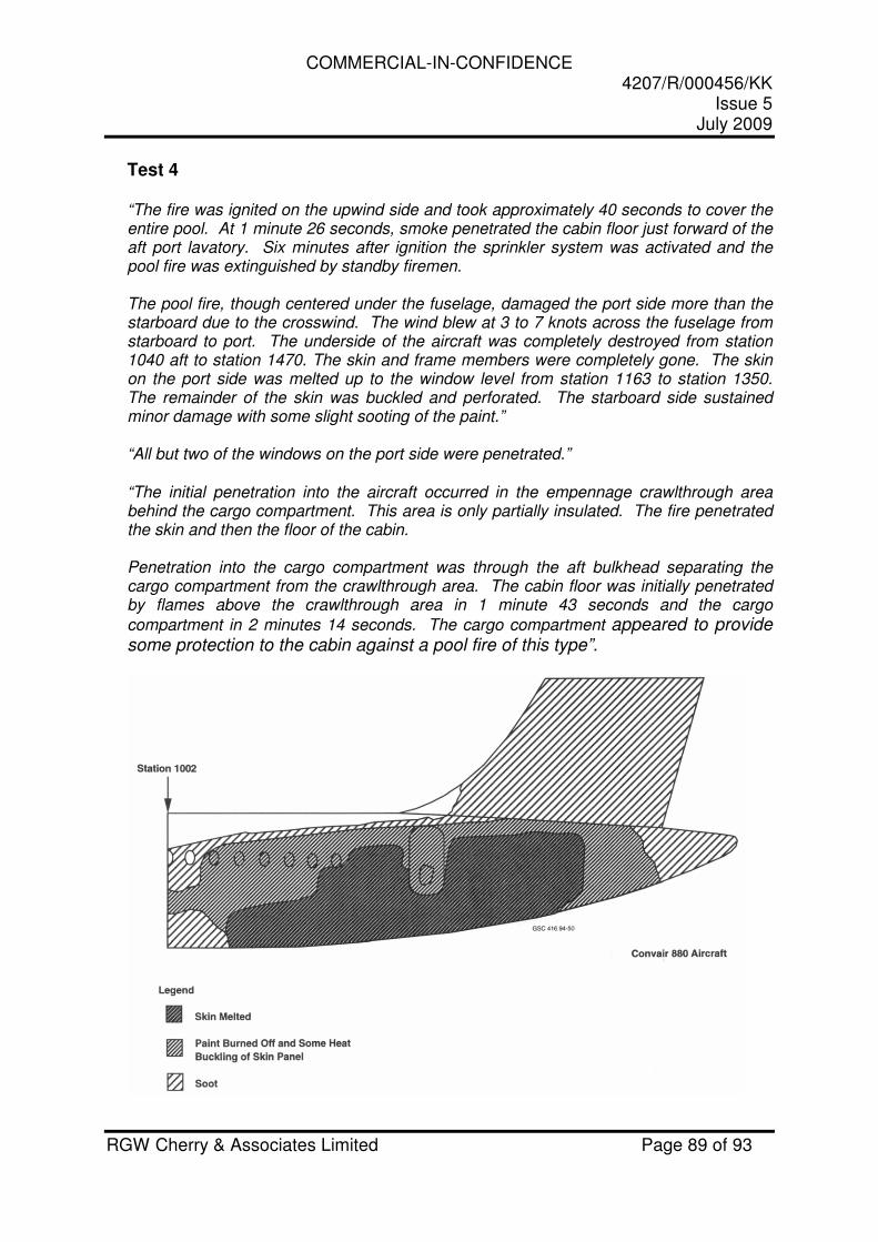
COMMERCIAL-IN-CONFIDENCE 4207/R/000456/KK
Issue 5 July 2009
RGW Cherry & Associates Limited Page 89 of 93
Test 4 “The fire was ignited on the upwind side and took approximately 40 seconds to cover the entire pool. At 1 minute 26 seconds, smoke penetrated the cabin floor just forward of the aft port lavatory. Six minutes after ignition the sprinkler system was activated and the pool fire was extinguished by standby firemen. The pool fire, though centered under the fuselage, damaged the port side more than the starboard due to the crosswind. The wind blew at 3 to 7 knots across the fuselage from starboard to port. The underside of the aircraft was completely destroyed from station 1040 aft to station 1470. The skin and frame members were completely gone. The skin on the port side was melted up to the window level from station 1163 to station 1350. The remainder of the skin was buckled and perforated. The starboard side sustained minor damage with some slight sooting of the paint.” “All but two of the windows on the port side were penetrated.” “The initial penetration into the aircraft occurred in the empennage crawlthrough area behind the cargo compartment. This area is only partially insulated. The fire penetrated the skin and then the floor of the cabin. Penetration into the cargo compartment was through the aft bulkhead separating the cargo compartment from the crawlthrough area. The cabin floor was initially penetrated by flames above the crawlthrough area in 1 minute 43 seconds and the cargo
compartment in 2 minutes 14 seconds. The cargo compartment appeared to provide some protection to the cabin against a pool fire of this type”.
COMMERCIAL-IN-CONFIDENCE 4207/R/000456/KK
Issue 5 July 2009
RGW Cherry & Associates Limited Page 90 of 93
Observation 4.1 The elapsed time from when the pool fire had fully established to when smoke penetrated the cabin floor was 46 seconds. In this time the lower fuselage skin had melted. Test 4 indicates the capability of a fuel fire to melt the lower fuselage skin in around 46 seconds. Observation 4.2 The elapsed time from when the pool fire had fully established to when extinguishing commenced was 5 minutes and 20 seconds. In this time, the skin had melted up to the window level. Test 4 indicates the capability of a fuel fire to melt the upper fuselage skin within 5 minutes and 20 seconds. Observation 4.3 The elapsed time from when the pool fire had fully established to when extinguishing commenced was 5 minutes and 20 seconds. In this time, all but two of the windows on the port side were penetrated. Test 4 indicates the capability of a fuel fire to penetrate through the cabin windows within 5 minutes and 20 seconds.
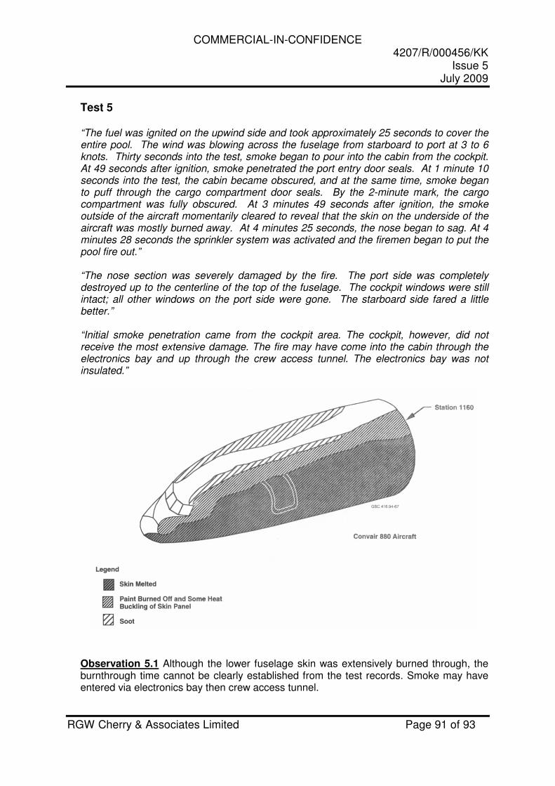
COMMERCIAL-IN-CONFIDENCE 4207/R/000456/KK
Issue 5 July 2009
RGW Cherry & Associates Limited Page 91 of 93
Test 5 “The fuel was ignited on the upwind side and took approximately 25 seconds to cover the entire pool. The wind was blowing across the fuselage from starboard to port at 3 to 6 knots. Thirty seconds into the test, smoke began to pour into the cabin from the cockpit. At 49 seconds after ignition, smoke penetrated the port entry door seals. At 1 minute 10 seconds into the test, the cabin became obscured, and at the same time, smoke began to puff through the cargo compartment door seals. By the 2-minute mark, the cargo compartment was fully obscured. At 3 minutes 49 seconds after ignition, the smoke outside of the aircraft momentarily cleared to reveal that the skin on the underside of the aircraft was mostly burned away. At 4 minutes 25 seconds, the nose began to sag. At 4 minutes 28 seconds the sprinkler system was activated and the firemen began to put the pool fire out.” “The nose section was severely damaged by the fire. The port side was completely destroyed up to the centerline of the top of the fuselage. The cockpit windows were still intact; all other windows on the port side were gone. The starboard side fared a little better.” “Initial smoke penetration came from the cockpit area. The cockpit, however, did not receive the most extensive damage. The fire may have come into the cabin through the electronics bay and up through the crew access tunnel. The electronics bay was not insulated.”
Observation 5.1 Although the lower fuselage skin was extensively burned through, the burnthrough time cannot be clearly established from the test records. Smoke may have entered via electronics bay then crew access tunnel.
COMMERCIAL-IN-CONFIDENCE 4207/R/000456/KK
Issue 5 July 2009
RGW Cherry & Associates Limited Page 92 of 93
Observation 5.2 The elapsed time from when the pool fire had fully established to when extinguishing commenced was 4 minutes and 3 seconds. In this time the port side was completely destroyed up to the top of the fuselage. Test 5 indicates the capability of a fuel fire to melt the upper fuselage skin within 4 minutes and 3 seconds. Observation 5.3 The elapsed time from when the pool fire had fully established to when extinguishing commenced was 4 minutes and 3 seconds. In this time, all windows on the port side were ‘gone’. Test 5 indicates the capability of a fuel fire to penetrate through the cabin windows within 4 minutes and 3 seconds.
COMMERCIAL-IN-CONFIDENCE 4207/R/000456/KK
Issue 5 July 2009
RGW Cherry & Associates Limited Page 93 of 93
Test 6 “The fire took approximately 25 seconds to reach a fully developed state. At 40 seconds there was a small explosion under the fuselage. At 1 minute 5 seconds, smoke began to rise from the floor of the cabin at station 980. At the 4-minute mark the landing gear collapsed and the fuselage fell to the ground. The pool fire was extinguished at this time by the standby firemen.” “The port side skin that was forward of the leading edge of the wing was completely burned away up to the top of the fuselage.”
“The only penetration into the cabin occurred on the aft starboard side where the windows were burned away. Here the sidewall panels were damaged. There was no ceiling overhead fire in this test. The acoustical insulation remained in place and supplied the inner sidewall panels with substantial protection from the fire.” Observation 6.1 The elapsed time from when the pool fire had fully established to when smoke began to rise from the cabin floor was 40 seconds. In this time the lower fuselage skin had melted. Test 6 indicates the capability of a fuel fire to melt the lower fuselage skin in around 40 seconds. Observation 6.2 The elapsed time from when the pool fire had fully established to when extinguishing commenced was 3 minutes and 35 seconds. In this time the skin had melted up to the window level. Test 6 indicates the capability of a fuel fire to melt the upper fuselage skin within 3 minutes and 35 seconds.
Observation 6.3 The elapsed time from when the pool fire had fully established to when extinguishing commenced was 3 minutes and 35 seconds. In this time the windows on the starboard side had burned away allowing fire penetration. Test 6 indicates the capability of a fuel fire to penetrate through the cabin windows within 3 minutes and 35 seconds.