A Logical Model for the State of Iowa Department of ... of Transportation’s Linear Referencing...
68
A Logical Model for the State of Iowa Department of Transportation’s Linear Referencing System Summary Document May 2000 Prepared by 2836 Jefferson Drive Phone: 608-437-6701 Blue Mounds, WI 53517 Facsimile: 608-437-6702 E-mail: [email protected] URL: http://www.fairview-industries.com GeoDigm – Geographical Paradigm Computing, Inc. P.O. Box 40483 Phone: 505-833-3309 Albuquerque, NM 87196 Facsimile: 505-833-5582 E-mail: [email protected] 108 Canvasback Court Phone: 502-695-9314 Frankfort, KY 40601-8641 Facsimile: 502-695-9316 E-mail: [email protected] URL: http://www.bluegrassgis.com Dr. Alan Vonderohe W10751 Wildwood Way, Route 3 Poynette, WI 53955 E-mail: [email protected] 1716 Fordem Avenue Phone: 608-241-7100 Madison, Wisconsin 53704 Facsimile: 608-241-7116 E-mail: [email protected] URL: http://www.geoanalytics.com
Transcript of A Logical Model for the State of Iowa Department of ... of Transportation’s Linear Referencing...
A Logical Model for the State of Iowa
Department of Transportation’s Linear Referencing System
Summary Document
May 2000
Prepared by
2836 Jefferson Drive Phone: 608-437-6701 Blue Mounds, WI 53517 Facsimile: 608-437-6702 E-mail: [email protected] URL: http://www.fairview-industries.com
GeoDigm – Geographical Paradigm Computing, Inc. P.O. Box 40483 Phone: 505-833-3309 Albuquerque, NM 87196 Facsimile: 505-833-5582 E-mail: [email protected]
108 Canvasback Court Phone: 502-695-9314 Frankfort, KY 40601-8641 Facsimile: 502-695-9316 E-mail: [email protected] URL: http://www.bluegrassgis.com
Dr. Alan Vonderohe W10751 Wildwood Way, Route 3
Poynette, WI 53955 E-mail: [email protected]
1716 Fordem Avenue Phone: 608-241-7100 Madison, Wisconsin 53704 Facsimile: 608-241-7116 E-mail: [email protected] URL: http://www.geoanalytics.com

Table of Contents
I. EXECUTIVE SUMMARY .................................................................................................. 1
A. BACKGROUND .................................................................................................................. 1 B. APPROACH....................................................................................................................... 1 C. LRS LOGICAL DESIGN RESULTS ........................................................................................ 2 D. CONCLUSION ................................................................................................................... 3
II. OVERVIEW........................................................................................................................ 4
III. CONCEPTUAL DESIGN REVIEW .............................................................................. 5
A. OPERATIONAL ARCHITECTURE ......................................................................................... 6 B. DECISION SUPPORT ARCHITECTURE ................................................................................. 9
IV. LOGICAL DESIGN APPROACH............................................................................... 10
V. OPERATIONAL ARCHITECTURE REQUIREMENTS................................................ 11
A. DATUM MANAGEMENT SUBSYSTEM ............................................................................... 14 B. ROUTE MANAGEMENT SUBSYSTEM ................................................................................. 18 C. LRS MILEPOINT LRM..................................................................................................... 25 D. REFERENCE POST MANAGEMENT SUBSYSTEM ................................................................. 27 E. STATIONING MANAGEMENT SUBSYSTEM ........................................................................ 29 F. SEGMENTAL MANAGEMENT SUBSYSTEM ........................................................................ 33 G. COORDINATE – ROUTE MANAGEMENT SUBSYSTEM ........................................................ 36 H. LINK-NODE MANAGEMENT SUBSYSTEM ......................................................................... 40 I. LITERAL DESCRIPTION MANAGEMENT SUBSYSTEM......................................................... 41 J. LRS MANAGEMENT ....................................................................................................... 45
VI. DECISION SUPPORT ARCHITECTURE REQUIREMENTS .................................. 51
VII. CONCLUSION ............................................................................................................ 57
APPENDIX A – GLOSSARY....................................................................................................... 61

List of Figures
Figure 1: NCHRP 20-27(2) Model Schematic.............................................................................. 6 Figure 2: Iowa Conceptual Design - A Modified 20-27(2) Model .............................................. 7 Figure 3: LRS Operational Architecture ..................................................................................... 8 Figure 4: Iowa DOT GeoData Warehouse Architecture ............................................................. 9 Figure 5: A General Roadway Transport System..................................................................... 11 Figure 6: The Key LRS Datum Components ............................................................................ 14 Figure 7: The Long Term Cartography to be Used by the LRS ................................................ 15 Figure 8: Datum Data Model .................................................................................................... 16 Figure 9: The LRS Transport Network ..................................................................................... 20 Figure 11: The LRS Posted Routes ............................................................................................ 20 Figure 12: Route Data Model.................................................................................................... 22 Figure 13: The LRS Milepoint ................................................................................................... 25 Figure 14: The LRS Reference Post ........................................................................................... 27 Figure 15: Reference Post Data Model...................................................................................... 28 Figure 16: The LRS Stationing .................................................................................................. 29 Figure 17: Stationing Data Model ............................................................................................. 31 Figure 18: The GIMS Segmental Method.................................................................................. 33 Figure 19: Segmental Data Model............................................................................................. 34 Figure 20: The LRS Coordinate – Route.................................................................................... 36 Figure 21: Coordinate-Route Data Model ................................................................................ 38 Figure 22: The LRS Literal Description..................................................................................... 41 Figure 23: Literal Description Data Model ............................................................................... 43 Figure 24: LRS Component Data Model................................................................................... 47 Figure 25: LRS Organizational Architecture............................................................................. 48 Figure 26: Logical Design Operational Model.......................................................................... 57
List of Tables
Table 1: Overall Subsystem Manager & Staff Descriptions ...................................................... 12 Table 2: Linear Datum Manager & Staff Roles ......................................................................... 17 Table 3: Route Subsystem Manager & Staff Roles .................................................................... 23 Table 4: Reference Post Subsystem Manager & Staff Roles...................................................... 28 Table 5: Stationing Subsystem Manager & Staff Roles ............................................................. 32 Table 6: Segmental Subsystem Manager & Staff Roles............................................................. 35 Table 7: Coordinate-Route Subsystem Manager & Staff Roles ................................................ 39 Table 8: Literal Description Subsystem Manager & Staff Roles ............................................... 44 Table 9: LRS Component Sponsor and Board Roles................................................................. 49 Table 10: LRS Manager & Staff Roles ....................................................................................... 50 Table 11: GeoData Warehouse Organizational and Technology Considerations .................... 52 Table 12: GDW Manager & Staff Roles..................................................................................... 55
A Logical Design for the Iowa DOT
Linear Referencing System
Summary Document
I. EXECUTIVE SUMMARY
A. Background In April 1999, the Iowa Department of Transportation (DOT) began a project to develop a Linear Referencing System (LRS) for the Department. A linear reference system’s primary purpose is to allow the DOT to integrate disparate data by using linear reference method (LRM) locations as the common link between them. These LRMs locate transportation objects (signs, pavement) and events (crashes, traffic collection section) relative to a position along a transportation feature (e.g. a roadway). Referencing items by milepost is an example of a DOT LRM. The DOT has identified six key LRMs used in the Department. The purpose of the Iowa DOT LRS Development Project is to improve how the DOT manages and applies its LRMs by developing a linear reference system to integrate these methods and their associated business data. Specifically, there are five project objectives:
1. The LRS will provide improved data integration and access. 2. The LRS will provide improved accuracy of the features referenced to the road network. 3. The LRS will provide a way to linearly locate roadway data along all public roads in the
State. 4. The LRS will help minimize redundancy in DOT database systems. 5. The LRS will help minimize data maintenance that is needed due to changes in the
transportation network. Iowa DOT contracted with GeoAnalytics, Inc. to provide counsel and facilitate Department decisions related to improved linear reference management. In addition, GeoAnalytics will be providing technical support services for the testing and validation of LRS design decisions. The Project Team assigned to this project is composed of both GeoAnalytics and Iowa DOT staff members. A Project Steering Committee, composed of representatives from all Divisions, guides the Project Team.
B. Approach This project has been broken into several tasks. Recently, the Project Team successfully completed the third task, Logical Design. Both a Needs Assessment and Conceptual Design preceded this Logical Design. The Needs Assessment characterized the need for the LRS, familiarized the Project Team (particularly GeoAnalytics) with these needs, and prepared the Project Team for the next tasks. The Conceptual Design defined the overall structure of the
Logical Design Summary Document
Page 2
LRS, illustrated how it interacts with existing DOT applications, documented key LRS objectives and constraints, and set the scope for the Logical Design. The Logical Design successfully captured Iowa DOT’s detailed requirements for maintaining and using the LRS. The result of the Logical Design is a blue print of business needs independent of technological and organizational structures. In essence, the Logical Design captures what is needed to make the LRS work, independent of how the requirements will be met. Physical Design is where the Project Team determines how to meet LRS requirements in Iowa DOT’s technological and organizational environments. The Logical Design provides a checklist to the Project Team so the computer and organization solutions meet the LRS needs of Iowa DOT. Subsequent to the Physical Design, the Project Team will perform a pilot task that will construct certain components of the LRS and test them against pre-determined benchmarks.
C. LRS Logical Design Results The completed Logical Design includes operational requirements and decision support requirements. Operational requirements cover LRS maintenance. The operational requirements are grouped into seven subsystems that manage the LRS. The management subsystems are the Linear Datum, Route (transportation networks, routes, and the LRS Milepoint LRM), Segmental LRM, Stationing LRM, Reference Post LRM (previously called milepost), Literal Description LRM, and Coordinate Route LRM. The decision support requirements cover what is needed by the LRS to support business data access, integration, and analysis. The LRS decision support requirements are satisfied by adding additional capabilities to the GeoData Warehouse. Both operational and decision support requirements include comprehensive subsets of requirements called models. A data model captures details about data descriptions and characteristics. A process model captures the processes required to create, modify, or use the LRS data. It should be noted that the Project Team has successfully applied the NCHRP 20-27(2) LRS industry template to the Logical Design as required by the project contract. The Logical Design also includes an organizational model. This model documents what roles and related skills will be needed to manage and successfully apply the LRS over time. Finally, the Logical Design describes general technology requirements needed to support these models. The following characterizes the Logical Design results, based on the five project objectives mentioned above: 1. The LRS will provide improved data integration and access. The Logical Design captures the
requirements to integrate disparate business data (e.g., pavement type, crashes, ADT) regardless of which supported LRM is used (e.g., Reference Post, Literal Description). The Logical Design also documents the requirements that will allow users to access and analyze this business data in an ad hoc or pre-defined fashion via Iowa DOT’s GeoData Warehouse.
Iowa DOT LRS Development Project
Page 3
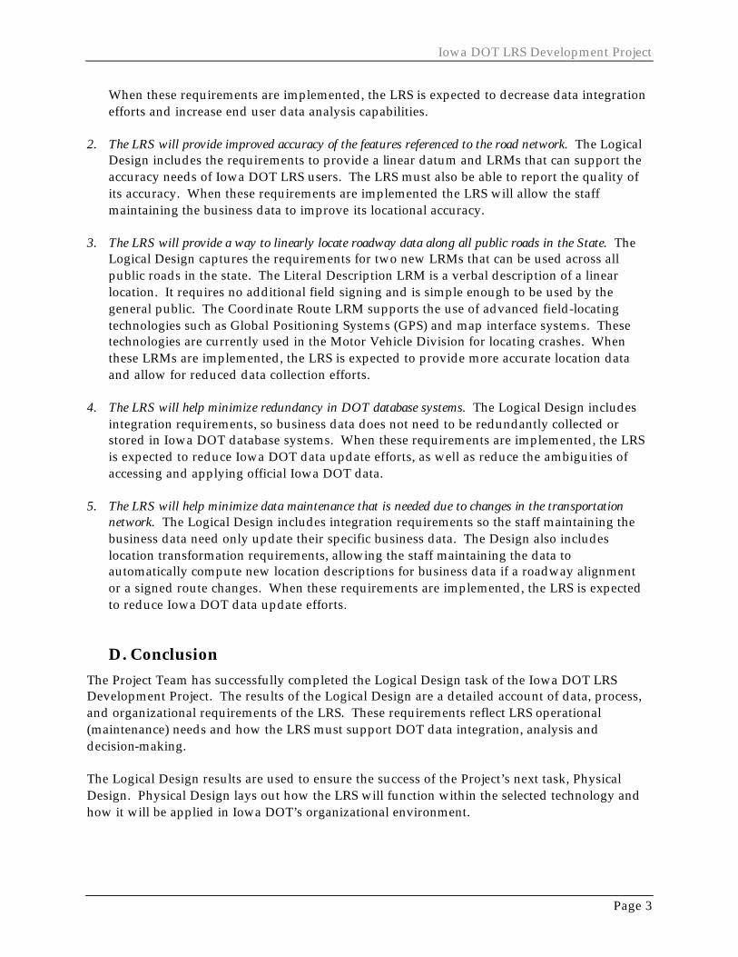
When these requirements are implemented, the LRS is expected to decrease data integration efforts and increase end user data analysis capabilities.
2. The LRS will provide improved accuracy of the features referenced to the road network. The Logical
Design includes the requirements to provide a linear datum and LRMs that can support the accuracy needs of Iowa DOT LRS users. The LRS must also be able to report the quality of its accuracy. When these requirements are implemented the LRS will allow the staff maintaining the business data to improve its locational accuracy.
3. The LRS will provide a way to linearly locate roadway data along all public roads in the State. The
Logical Design captures the requirements for two new LRMs that can be used across all public roads in the state. The Literal Description LRM is a verbal description of a linear location. It requires no additional field signing and is simple enough to be used by the general public. The Coordinate Route LRM supports the use of advanced field-locating technologies such as Global Positioning Systems (GPS) and map interface systems. These technologies are currently used in the Motor Vehicle Division for locating crashes. When these LRMs are implemented, the LRS is expected to provide more accurate location data and allow for reduced data collection efforts.
4. The LRS will help minimize redundancy in DOT database systems. The Logical Design includes
integration requirements, so business data does not need to be redundantly collected or stored in Iowa DOT database systems. When these requirements are implemented, the LRS is expected to reduce Iowa DOT data update efforts, as well as reduce the ambiguities of accessing and applying official Iowa DOT data.
5. The LRS will help minimize data maintenance that is needed due to changes in the transportation
network. The Logical Design includes integration requirements so the staff maintaining the business data need only update their specific business data. The Design also includes location transformation requirements, allowing the staff maintaining the data to automatically compute new location descriptions for business data if a roadway alignment or a signed route changes. When these requirements are implemented, the LRS is expected to reduce Iowa DOT data update efforts.
D. Conclusion The Project Team has successfully completed the Logical Design task of the Iowa DOT LRS Development Project. The results of the Logical Design are a detailed account of data, process, and organizational requirements of the LRS. These requirements reflect LRS operational (maintenance) needs and how the LRS must support DOT data integration, analysis and decision-making. The Logical Design results are used to ensure the success of the Project’s next task, Physical Design. Physical Design lays out how the LRS will function within the selected technology and how it will be applied in Iowa DOT’s organizational environment.

Logical Design Summary Document
Page 4
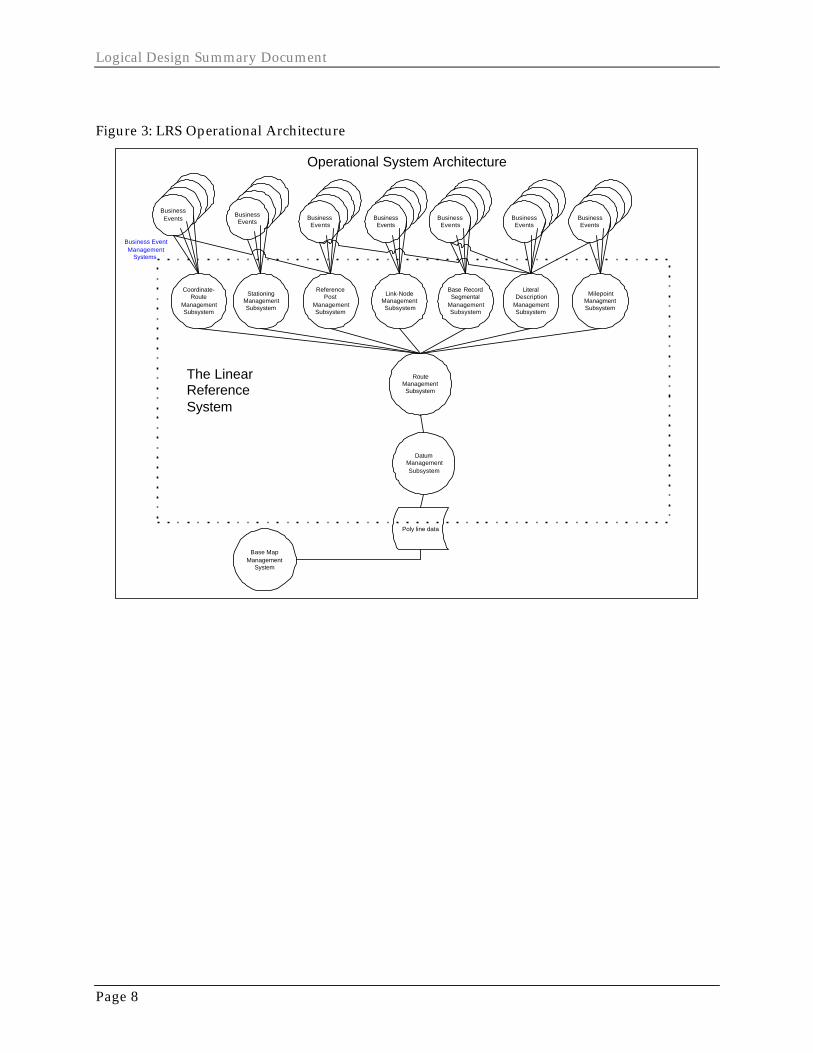
II. OVERVIEW The purpose of this document is to provide the reader with a non-technical summary of the Logical Design Model for the Iowa DOT Linear Referencing System (LRS). The Logical Design Model captures the management and use requirements of the LRS. Requirements describe what is needed to make the LRS work at DOT – not how to make it work. The result of Logical Design is an organized set of business requirements that lead the physical design. Physical design is when we figure out how to make it work given DOT’s technology, process, data, and organizational environments. The project team organized the requirements gathering based on the Conceptual Design Model from this project. That Model describes two architectures: operational and decision support. The operational architecture is how the LRS is managed over time. The Conceptual Design Model decomposed the operational architecture into subsystems within the LRS. Figure 3, in Section III, provides a graphic of these subsystems. Most of the logical design was spent gathering LRS data requirements captured in this architecture. The decision support architecture is how the LRS is applied to DOT business functions. At Iowa DOT, the GeoData Warehouse (GDW) is where access and application of LRS data will occur. Logical design activities focused on gathering LRS data access, integration and analysis requirements and are based on this architecture. The first part of this document contains a brief review of the Conceptual Model, followed by a description of the logical design approach used to capture the requirements. Next the document outlines the key requirements of the LRS, first for the Operational Architecture, and then for the GeoData Warehouse architecture. Within the Operational Architecture, the requirements are described for each LRS subsystem. Finally, a conclusion section is provided that summaries the data, process, technology, and organizational requirements of the LRS. The conclusion also describes how the requirement discovery process modified the conceptual design. It is important to note that logical design is never quite complete. Not unlike roadway design, system design intent is to remove as much uncertainty, as possible, prior to actual construction. But there will be requirements that need to be modified and others discovered along the way. This is expected. Consequently, the printed version of this document will become out-dated as the project continues, and this will continue over the life of the LRS. However, at this time the logical design model contains the core requirements of the LRS. There is a separate, technical document for those who require more specific information. The information is formatted for system design staff. In addition, the technical document contains an overview to help understand these formats. The technical document is dynamic because it is where logical requirements are detailed. As requirements change, they will be recorded in the technical document.
Iowa DOT LRS Development Project
Page 5
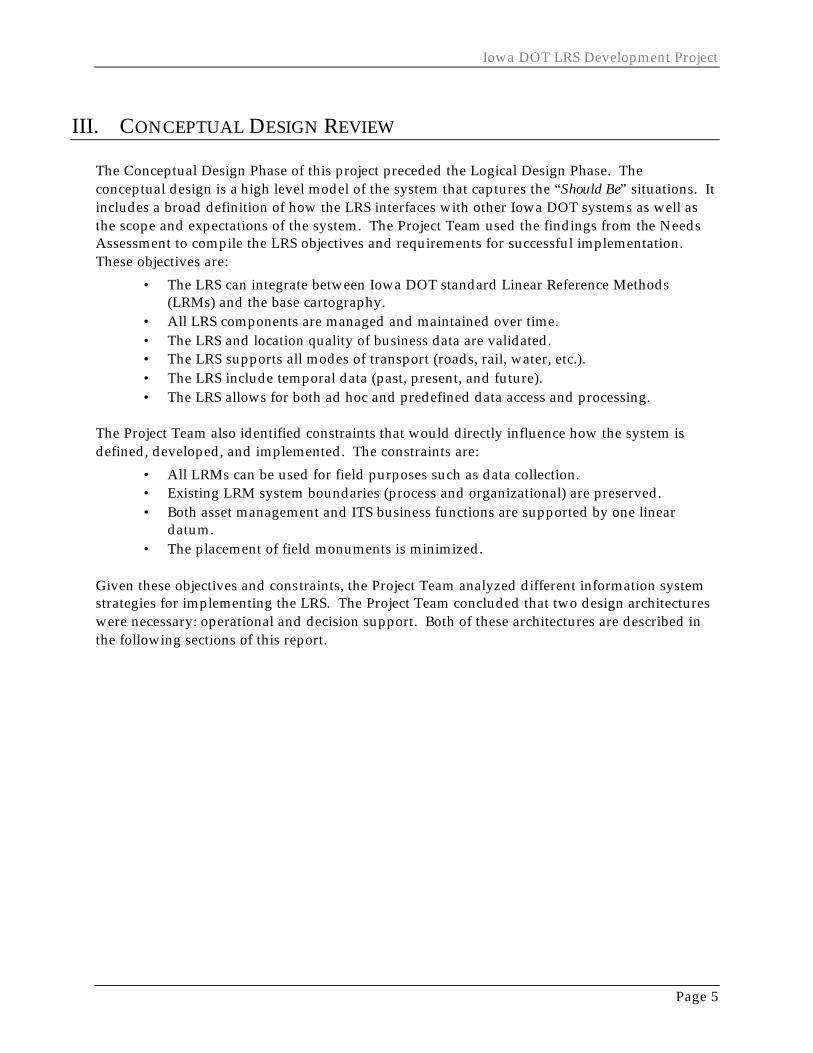
III. CONCEPTUAL DESIGN REVIEW The Conceptual Design Phase of this project preceded the Logical Design Phase. The conceptual design is a high level model of the system that captures the “Should Be” situations. It includes a broad definition of how the LRS interfaces with other Iowa DOT systems as well as the scope and expectations of the system. The Project Team used the findings from the Needs Assessment to compile the LRS objectives and requirements for successful implementation. These objectives are:
• The LRS can integrate between Iowa DOT standard Linear Reference Methods (LRMs) and the base cartography.
• All LRS components are managed and maintained over time. • The LRS and location quality of business data are validated. • The LRS supports all modes of transport (roads, rail, water, etc.). • The LRS include temporal data (past, present, and future). • The LRS allows for both ad hoc and predefined data access and processing.
The Project Team also identified constraints that would directly influence how the system is defined, developed, and implemented. The constraints are:
• All LRMs can be used for field purposes such as data collection. • Existing LRM system boundaries (process and organizational) are preserved. • Both asset management and ITS business functions are supported by one linear
datum. • The placement of field monuments is minimized.
Given these objectives and constraints, the Project Team analyzed different information system strategies for implementing the LRS. The Project Team concluded that two design architectures were necessary: operational and decision support. Both of these architectures are described in the following sections of this report.
Logical Design Summary Document
Page 6
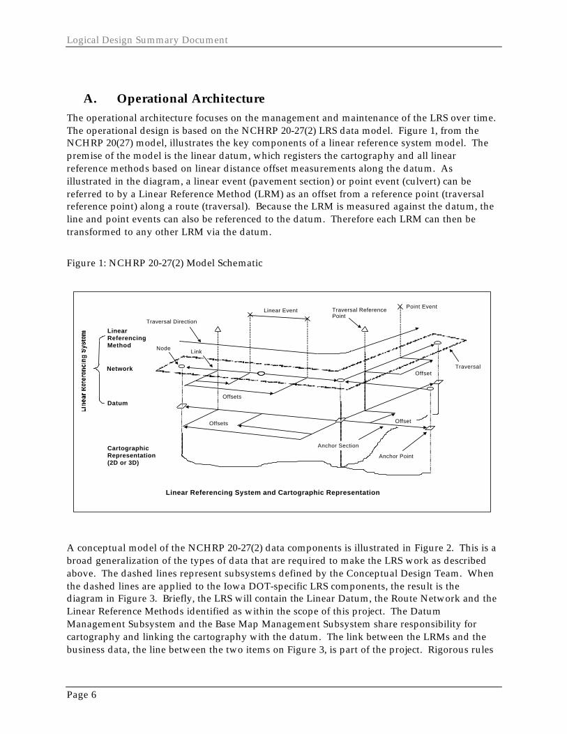
A. Operational Architecture The operational architecture focuses on the management and maintenance of the LRS over time. The operational design is based on the NCHRP 20-27(2) LRS data model. Figure 1, from the NCHRP 20(27) model, illustrates the key components of a linear reference system model. The premise of the model is the linear datum, which registers the cartography and all linear reference methods based on linear distance offset measurements along the datum. As illustrated in the diagram, a linear event (pavement section) or point event (culvert) can be referred to by a Linear Reference Method (LRM) as an offset from a reference point (traversal reference point) along a route (traversal). Because the LRM is measured against the datum, the line and point events can also be referenced to the datum. Therefore each LRM can then be transformed to any other LRM via the datum.
Figure 1: NCHRP 20-27(2) Model Schematic
Traversal Direction
Linear Event Point Event Traversal Reference
Point
Offsets
Offsets
Offset
Offset
Node Link
Traversal
Anchor Point
Anchor Section
Datum
Network
Linear Referencing Method
Cartographic Representation (2D or 3D)
Linear Referencing System and Cartographic Representation
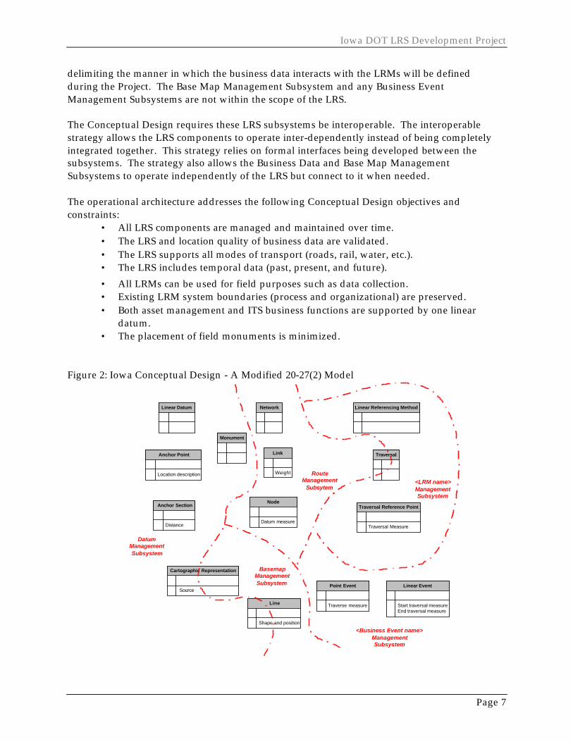
A conceptual model of the NCHRP 20-27(2) data components is illustrated in Figure 2. This is a broad generalization of the types of data that are required to make the LRS work as described above. The dashed lines represent subsystems defined by the Conceptual Design Team. When the dashed lines are applied to the Iowa DOT-specific LRS components, the result is the diagram in Figure 3. Briefly, the LRS will contain the Linear Datum, the Route Network and the Linear Reference Methods identified as within the scope of this project. The Datum Management Subsystem and the Base Map Management Subsystem share responsibility for cartography and linking the cartography with the datum. The link between the LRMs and the business data, the line between the two items on Figure 3, is part of the project. Rigorous rules
Iowa DOT LRS Development Project
Page 7
delimiting the manner in which the business data interacts with the LRMs will be defined during the Project. The Base Map Management Subsystem and any Business Event Management Subsystems are not within the scope of the LRS. The Conceptual Design requires these LRS subsystems be interoperable. The interoperable strategy allows the LRS components to operate inter-dependently instead of being completely integrated together. This strategy relies on formal interfaces being developed between the subsystems. The strategy also allows the Business Data and Base Map Management Subsystems to operate independently of the LRS but connect to it when needed. The operational architecture addresses the following Conceptual Design objectives and constraints:
• All LRS components are managed and maintained over time. • The LRS and location quality of business data are validated. • The LRS supports all modes of transport (roads, rail, water, etc.). • The LRS includes temporal data (past, present, and future).
• All LRMs can be used for field purposes such as data collection. • Existing LRM system boundaries (process and organizational) are preserved. • Both asset management and ITS business functions are supported by one linear
datum. • The placement of field monuments is minimized.
Figure 2: Iowa Conceptual Design - A Modified 20-27(2) Model
Linear Datum Network Linear Referencing Method
Location description
Anchor Point
Distance
Anchor Section
Source
Cartographic Representation
Datum measure
Node
Weight
Link Traversal
Traversal Measure
Traversal Reference Point
Traverse measure
Point Event
Start traversal measureEnd traversal measure
Linear Event
Shape and position
Line
Monument
<LRM name>ManagementSubsystem
RouteManagement
Subsytem
DatumManagementSubsystem
BasemapManagementSubsystem
<Business Event name>ManagementSubsystem
Logical Design Summary Document
Page 8
Figure 3: LRS Operational Architecture
Poly line data
The LinearReferenceSystem
Operational System Architecture
Business EventManagement
Systems
DatumManagementSubsystem
Base MapManagement
System
RouteManagementSubsystem
ReferencePost
ManagementSubsystem
MilepointManagmentSubsystem
LiteralDescription
ManagementSubsystem
Coordinate-Route
ManagementSubsystem
StationingManagementSubsystem
Base RecordSegmental
ManagementSubsystem
Link-NodeManagementSubsystem
BusinessEvents Business
EventsBusinessEvents
BusinessEvents
BusinessEvents
BusinessEvents
BusinessEvents
Iowa DOT LRS Development Project
Page 9
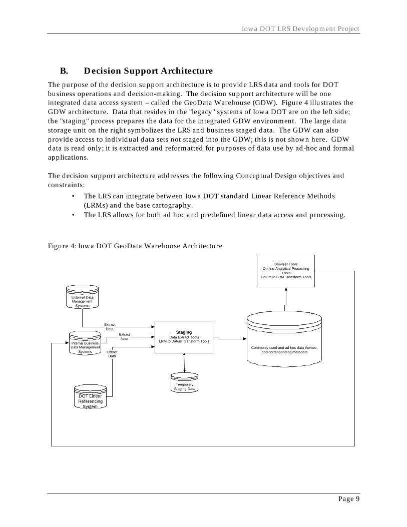
B. Decision Support Architecture The purpose of the decision support architecture is to provide LRS data and tools for DOT business operations and decision-making. The decision support architecture will be one integrated data access system – called the GeoData Warehouse (GDW). Figure 4 illustrates the GDW architecture. Data that resides in the "legacy" systems of Iowa DOT are on the left side; the "staging" process prepares the data for the integrated GDW environment. The large data storage unit on the right symbolizes the LRS and business staged data. The GDW can also provide access to individual data sets not staged into the GDW; this is not shown here. GDW data is read only; it is extracted and reformatted for purposes of data use by ad-hoc and formal applications. The decision support architecture addresses the following Conceptual Design objectives and constraints:
• The LRS can integrate between Iowa DOT standard Linear Reference Methods (LRMs) and the base cartography.
• The LRS allows for both ad hoc and predefined linear data access and processing.
Figure 4: Iowa DOT GeoData Warehouse Architecture
DOT LinearReferencing
System
Internal BusinessData Management
Systems
External DataManagement
Systems
Commonly used and ad hoc data themes,and corresponding metadataExtract
Data
ExtractData
ExtractData
StagingData Extract Tools
LRM to Datum Transform Tools
Browser ToolsOn-line Analytical Processing
ToolsDatum to LRM Transform Tools
TemporaryStaging Data
Logical Design Summary Document
Page 10
IV. LOGICAL DESIGN APPROACH The purpose of logical design is to determine and detail the requirements of the operational and GDW architectures identified in the Conceptual Design. Requirements are “what” are needed to make the LRS work at DOT. The result of Logical Design is a blue print of business needs that can be implemented in any specific technological and organizational environment (this project will apply the logical design results to the DOT environments identified in the physical design phase). Requirements include specifics about data descriptions, characteristics, qualities, and basic performance needs. Requirements also include the processes that will create, modify, or be applied against the data. Finally, the Logical Design includes the roles and related skills needed to perform these processes, and the technology strategies needed to support these requirements. Requirements are typically recorded using constructs, called models, which make requirements gathering and recording more efficient, and therefore, make system development more efficient. Some examples of models for the data, process, and data/process interactions can be found in the Logical Design Technical Document. For this project, requirements were addressed by leveraging existing industry templates. These industry templates can be considered starter models. The DOT required the project be developed using the NCHRP 20-27(2) template as a model. The project team compiled detailed requirements on both the location needs of DOT business functions, and on what is needed to manage the LRS by reviewing existing documentation and holding requirements gathering workshops and interviews. The logical design team compiled these findings into the models. The project team clarified or validated the models by holding additional sessions with DOT staff. Typically, these sessions did not focus on the models, but on the requirements that they represent.
Iowa DOT LRS Development Project
Page 11
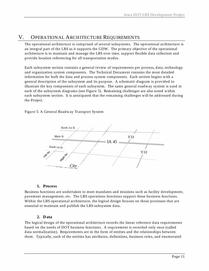
V. OPERATIONAL ARCHITECTURE REQUIREMENTS The operational architecture is comprised of several subsystems. The operational architecture is an integral part of the LRS as it supports the GDW. The primary objective of the operational architecture is to maintain and manage the LRS over time, support flexible data collection and provide location referencing for all transportation modes. Each subsystem section contains a general review of requirements per process, data, technology and organization system components. The Technical Document contains the most detailed information for both the data and process system components. Each section begins with a general description of the subsystem and its purpose. A schematic diagram is provided to illustrate the key components of each subsystem. The same general roadway system is used in each of the subsystem diagrams (see Figure 5). Remaining challenges are also noted within each subsystem section. It is anticipated that the remaining challenges will be addressed during the Project.
Figure 5: A General Roadway Transport System
IA 45
Y33
City
Main St
Maple A
ve
North 1st St
Oak Av
e
South 1st St
Y33
1. Process Business functions are undertaken to meet mandates and missions such as facility development, pavement management, etc. The LRS operations functions support these business functions. Within the LRS operational architecture, the logical design focuses on those processes that are essential to maintain and publish the LRS subsystem data.
2. Data The logical design of the operational architecture records the linear reference data requirements based on the needs of DOT business functions. A requirement is recorded only once (called data normalization). Requirements are in the form of entities and the relationships between them. Typically, each of the entities has attributes, definitions, business rules, and enumerated
Logical Design Summary Document
Page 12
values. This document lists general requirements and associates them to the data entity that captures that requirement.
3. Technology In logical design, the technological component lacks rigor or detail. For the LRS operation architecture, this component describes technologies, such as GPS and GIS, required for special data and processing needs. Because the DOT has IT standards, the most likely technology to handle the requirements is provided when possible.
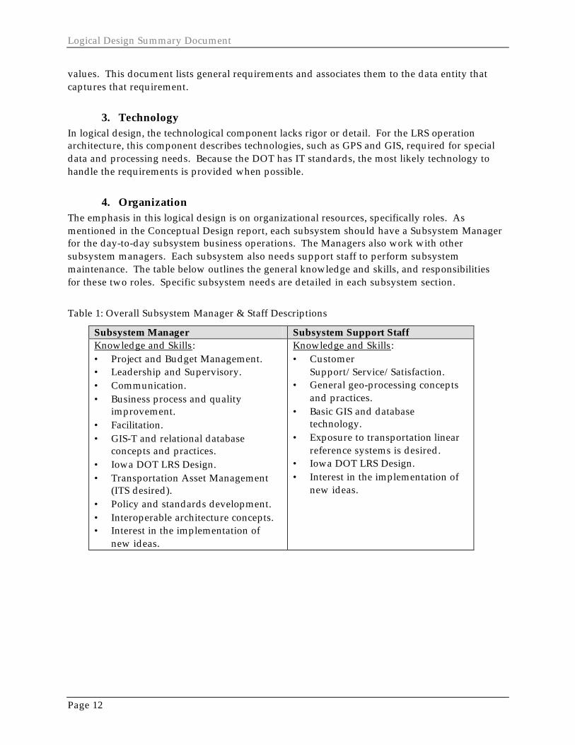
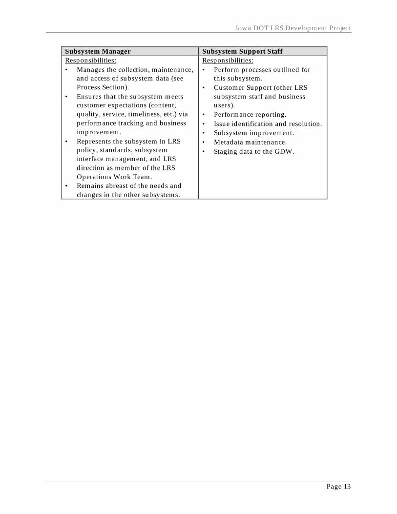
4. Organization The emphasis in this logical design is on organizational resources, specifically roles. As mentioned in the Conceptual Design report, each subsystem should have a Subsystem Manager for the day-to-day subsystem business operations. The Managers also work with other subsystem managers. Each subsystem also needs support staff to perform subsystem maintenance. The table below outlines the general knowledge and skills, and responsibilities for these two roles. Specific subsystem needs are detailed in each subsystem section.
Table 1: Overall Subsystem Manager & Staff Descriptions
Subsystem Manager Subsystem Support Staff Knowledge and Skills: • Project and Budget Management. • Leadership and Supervisory. • Communication. • Business process and quality
improvement. • Facilitation. • GIS-T and relational database
concepts and practices. • Iowa DOT LRS Design. • Transportation Asset Management
(ITS desired). • Policy and standards development. • Interoperable architecture concepts. • Interest in the implementation of
new ideas.
Knowledge and Skills: • Customer
Support/Service/Satisfaction. • General geo-processing concepts
and practices. • Basic GIS and database
technology. • Exposure to transportation linear
reference systems is desired. • Iowa DOT LRS Design. • Interest in the implementation of
new ideas.
Iowa DOT LRS Development Project
Page 13
Subsystem Manager Subsystem Support Staff Responsibilities: • Manages the collection, maintenance,
and access of subsystem data (see Process Section).
• Ensures that the subsystem meets customer expectations (content, quality, service, timeliness, etc.) via performance tracking and business improvement.
• Represents the subsystem in LRS policy, standards, subsystem interface management, and LRS direction as member of the LRS Operations Work Team.
• Remains abreast of the needs and changes in the other subsystems.
Responsibilities: • Perform processes outlined for
this subsystem. • Customer Support (other LRS
subsystem staff and business users).
• Performance reporting. • Issue identification and resolution. • Subsystem improvement. • Metadata maintenance. • Staging data to the GDW.
Logical Design Summary Document
Page 14
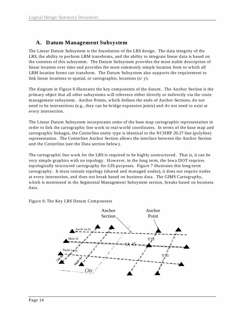
A. Datum Management Subsystem The Linear Datum Subsystem is the foundation of the LRS design. The data integrity of the LRS, the ability to perform LRM transforms, and the ability to integrate linear data is based on the contents of this subsystem. The Datum Subsystem provides the most stable description of linear location over time and provides the most commonly simple location form to which all LRM location forms can transform. The Datum Subsystem also supports the requirement to link linear locations to spatial, or cartographic, locations (x/y). The diagram in Figure 6 illustrates the key components of the datum. The Anchor Section is the primary object that all other subsystems will reference either directly or indirectly via the route management subsystem. Anchor Points, which defines the ends of Anchor Sections, do not need to be intersections (e.g., they can be bridge expansion joints) and do not need to exist at every intersection. The Linear Datum Subsystem incorporates some of the base map cartographic representation in order to link the cartographic line work to real-world coordinates. In terms of the base map and cartographic linkages, the Centerline entity type is identical to the NCHRP 20-27 line (polyline) representation. The Centerline Anchor Section allows the interface between the Anchor Section and the Centerline (see the Data section below). The cartographic line work for the LRS is required to be highly unstructured. That is, it can be very simple graphics with no topology. However, in the long term, the Iowa DOT requires topologically structured cartography for GIS purposes. Figure 7 illustrates this long-term cartography. It must contain topology (shared and managed nodes), it does not require nodes at every intersection, and does not break based on business data. The GIMS Cartography, which is mentioned in the Segmental Management Subsystem section, breaks based on business data.
Figure 6: The Key LRS Datum Components
IA 45
Y33
City
Main St
Maple A
ve
North 1st St
Oak Ave
South 1st St
Y33
AnchorPoint
AnchorSection

Iowa DOT LRS Development Project
Page 15
Figure 7: The Long Term Cartography to be Used by the LRS
IA 45
Y33
City
Main StMap
le Ave
North 1st St
Oak Ave
South 1st St
Y33
CenterlineNode
Centerline
1. Process As this is a new LRS component at Iowa DOT, the management process requirements are especially critical to capture. The process requirements are based on the NCHRP 20-27(2) design. The key elemental processes are to establish, place, position and publish the Linear Datum. In order to establish the Linear Datum, it must be designed – the design follows first, second, and third order design similar to geodetic control. The Datum must be surveyed or measured to acquire anchor point locations and anchor section distances. Finally, the datum must be published, making it accessible to other subsystems and LRS users.
2. Data The diagram in Figure 8, a simplified data model, illustrates the objects or entities that are required for this subsystem. The following bullets list the key requirements of the Linear Datum data components.
• Must describe the transportation facility uniquely. The anchor section is the primary element or building block that all other subsystems will reference either directly or indirectly. System Entities: Anchor Section, Anchor Point
• Must contain impedance - in this case distance – that is used as the basis of conversion and integration to which other linear and cartographic locations can be referenced. System Entities: Anchor Section, Centerline, and Centerline Anchor Section.
• This impedance distance must have identifiable certainty (error) and must describe the quality and condition of any single datum object’s accuracy. System Entities: Measurement Methods, Linear Datum Version.
• The components must be repeatedly identifiable in the field within accuracy requirements and distinguishable from each other. System Entities: Anchor Point Monument, Anchor Point Elevation.

Logical Design Summary Document
Page 16
• Must be able to represent the transportation facilities over time and in different states: future, current, and past. This means the datum must be able to support facilities when they are first conceptualized, when they are programmed, and throughout the facility development and operational process. System Entities: Anchor Section Proposed, Anchor Point Proposed, and Improvement Project.
• The datum existence is based on the improvement project from which facility changes are generated. System Entities: Improvement Project.
The design anticipates that, as technology and data collection methods improve, so will business requirements for data accuracy. The anchor section distances may also improve, and an adjustment to these distances will need to be made to accommodate these improvements. Therefore, the linear datum must be able to be versioned, much like geodetic control (e. g. , NAD27 was replaced by NAD83, etc.).
Figure 8: Datum Data Model
Anchor Point Monument
Centerline of CartographicRepresentation
Anchor Point Elevation
Anchor Section
Anchor SectionProposed
Linear DatumVersion
Measurement Methods
Improvement Project
Anchor Point
Anchor PointProposed
Centerline AnchorSection
Iowa DOT LRS Development Project
Page 17
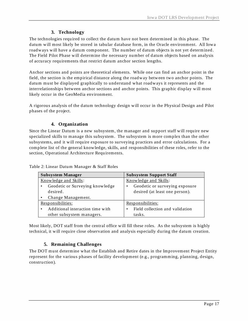
3. Technology The technologies required to collect the datum have not been determined in this phase. The datum will most likely be stored in tabular database form, in the Oracle environment. All Iowa roadways will have a datum component. The number of datum objects is not yet determined. The Field Pilot Phase will determine the necessary number of datum objects based on analysis of accuracy requirements that restrict datum anchor section lengths.
Anchor sections and points are theoretical elements. While one can find an anchor point in the field, the section is the empirical distance along the roadway between two anchor points. The datum must be displayed graphically to understand what roadways it represents and the interrelationships between anchor sections and anchor points. This graphic display will most likely occur in the GeoMedia environment.
A rigorous analysis of the datum technology design will occur in the Physical Design and Pilot phases of the project.
4. Organization Since the Linear Datum is a new subsystem, the manager and support staff will require new specialized skills to manage this subsystem. The subsystem is more complex than the other subsystems, and it will require exposure to surveying practices and error calculations. For a complete list of the general knowledge, skills, and responsibilities of these roles, refer to the section, Operational Architecture Requirements.
Table 2: Linear Datum Manager & Staff Roles
Subsystem Manager Subsystem Support Staff Knowledge and Skills: • Geodetic or Surveying knowledge
desired. • Change Management.
Knowledge and Skills: • Geodetic or surveying exposure
desired (at least one person).
Responsibilities: • Additional interaction time with
other subsystem managers.
Responsibilities: • Field collection and validation
tasks.
Most likely, DOT staff from the central office will fill these roles. As the subsystem is highly technical, it will require close observation and analysis especially during the datum creation.
5. Remaining Challenges The DOT must determine what the Establish and Retire dates in the Improvement Project Entity represent for the various phases of facility development (e.g., programming, planning, design, construction).

Logical Design Summary Document
Page 18
B. Route Management Subsystem The Route Management Subsystem, using the Linear Datum, is the next crucial piece of the LRS design. This subsystem will accommodate the need to traverse, or route, through the Iowa transportation networks and to refer to posted routes along the network. The Route Management Subsystem provides the underlying network and posted routes, to which most of DOT’s LRMs are dependent. The subsystem also has transport system qualities to allow for the capture of policy driven network definitions, to meet multi-modal requirements, and to meet multiple geographic extent requirements of the LRMs. A more specific description of the Subsystem is provided below.
The Transport Node and Transport Link entities capture the DOT navigable network requirements. The diagram in

Iowa DOT LRS Development Project
Page 19
Figure 9 illustrates the key network components. Transport Nodes exist at standard vehicular turning points. The Transport Nodes provides the topologic qualities to meet the routing requirements of the DOT. The Transport Link entity includes basic traffic flow indications (i.e., one way or bi-directional travel). These flows do not hold true for all DOT business functions (e.g., oversize or overweight routes). The Link State and Link Node entities capture network state requirements (open or closed) where the most current state is posted with the Transport Link and Transport Node. The Transport Link and Transport Node entities also support the requirement to transform between the Datum Subsystem and the LRS routes within this subsystem. Intersection entities will contain the transform requirements and are described in the Data section below. In general, the Transport Sequence and Transport Node Offset are intersection entities to capture which anchor section(s) correlate(s) with which Transport Link/Node, and vice versa. The System Route Link is a three-way intersection entity that associates Transport Links to Transport System, and routes. The Route Management Subsystem includes the LRS route requirements. Routes have independent qualities to meet concurrency and gap requirements. Figure 10 illustrates this independence with some of the posted route systems that are part of the LRS. Decisions have also been made regarding route directionality. All Roadways will use the federal standard to establish basic cardinality (from the SW, move N and E). This is required for establishing routes along links. While this is common practice on the state systems, it will be new for county, secondary, municipal, and park/institutional roadways. There may be other rules already established that must be followed (e.g., E911 signed routes).

Logical Design Summary Document
Page 20
Figure 9: The LRS Transport Network
IA 45
Y33
City
Main StMap
le Ave
North 1st St
Oak Ave
South 1st St
Y33
TransportNode
TransportLink
One Way
Figure 10: The LRS Posted Routes
IA 45
Y33
City
Main St
Maple A
ve
North 1st St
Oak Av
e
South 1st St
Y33
County Route‘Y33’
State Route‘IA 45E’
Municipal Route‘Main Street’
The Route Management Subsystem primarily focuses on route requirements for homogeneously signed, or posted, routes. However, some exceptions exist that must be accommodated by the LRS. Private roads may not necessarily have a posted name. However, they are included because the roadway requires at least one name in order to reference it in the LRS. Unofficial routes are included because of their local or regional significance or popularity of use (e.g., “Old 15”). The LRS does not contain other route types, such as snowplow, oversize/overweight, or maintenance routes. However, the subsystem data entities and processes can act as templates to capture other types of traversals.
The subsystem must also support detours. A detour must be a separate route from the route that is being detoured. For example, ‘I-80’ and ‘I-80 Detour’ are different routes within the state route system. This is necessary because roadway objects and events still need to be referenced along the original path, even though traffic has been detoured (mowing, sign inventory, improvement activities, etc.).

Iowa DOT LRS Development Project
Page 21
Another requirement is that a route must traverse an entire Transport Link (it cannot stop in the middle of a link). Links terminate only at intersections with other transportation features. Consequently, municipal street “routes” will extend beyond the municipal boundary to the next roadway intersection (see LRS Posted Routes figure above). In the past, DOT has used municipal boundaries as points of reference for locating other transportation objects and has terminated street names at these points. The DOT is discouraging users from applying such features as reference locations because of their ambiguous and volatile location in the field. The Route Management Subsystem also incorporates the LRS Milepoint LRM. The LRS Milepoint LRM can be completely derived from the information contained within the Route Management Subsystem. Therefore, it is logical to assign this LRM to this subsystem (see the LRS Milepoint LRM section in the document).
1. Process This subsystem is new for Iowa DOT, although some elements of routes, networks, and transport systems do exist at DOT (e.g., GIMS). The process requirements are briefly listed here to provide context to evaluating whether existing processes can be used to meet the LRS requirements. First, the network is established via transport links and nodes. Establishing the links and nodes means to add them, change their state (open or closed), and remove (retire) them. A route name is then established. Given these two elements, along with a transport system, a system route link can then be established. The system route links are assembled into a route, and then the distance of each system route link is determined. Finally, the route subsystem data must be published, which means make it accessible for use by other subsystems and LRS users.
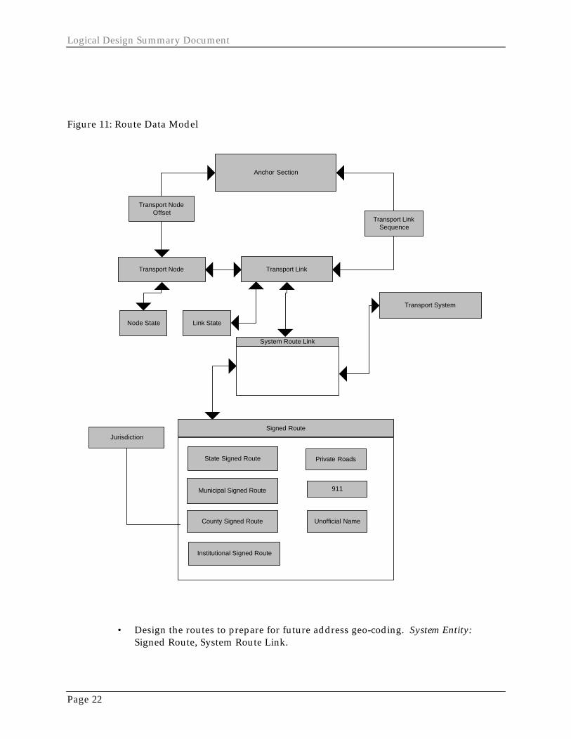
2. Data A simplified data model, Figure 11, illustrates the objects or entities that are required for this subsystem. The following bullets list the key requirements of the Route Management Subsystem data components. The system must be able to:
• Perform routing functions through the different transportation modes. System Entities: Transport Link and Transport Node provide connectivity and represent travel-ability
• Apply basic operating traffic flow to the network (one way, bi-directional) System Entities: Transport Link and Transport Node
• Provide the state of the network at any given point in time or range in time. System Attributes: Establish and retire dates as well as open and closed indicators over time.
• Describe the network and routes by mode, by extent (the “City of Ames”), subset (the State Roadway System in the City of Ames”, National Highway System). System Entities: Transport System, System Route Link.
• Describe federal, state, county, municipal, E911, private, and unofficial signed routes. System Entity: Signed Route.
Logical Design Summary Document
Page 22
Figure 11: Route Data Model
Jurisdiction
Transport Link
System Route Link
Transport System
Transport Node
Anchor Section
Signed Route
State Signed Route
County Signed Route
Institutional Signed Route
Unofficial Name
Municipal Signed Route 911
Private Roads
Node State Link State
Transport LinkSequence
Transport NodeOffset
• Design the routes to prepare for future address geo-coding. System Entity: Signed Route, System Route Link.
Iowa DOT LRS Development Project
Page 23
• Determine concurrency between all signed routes; that is, independently describe the signed routes that traverse the network. System Entity: System Route Link.
• Allow gaps in signed routes. System Entity: System Route Link. • Provide consistent and standard representation of route names across the
network. • Include ramps to support linear location referencing and ensure the names have
meaning to people. System Entities: System Route Link and Signed Route. • Include detours to support linear location referencing. System Entities: System
Route Link or the Signed Route. • Provide the state of the route at any given point in time or range in time. System
Entities: establish and retire dates on the System Route Link and Signed Route entities.
• Transform between the Datum Subsystem and the network. System Entities: Transport Node Offset and Transport Link Sequence.
• Transform between the network and the routes, and the LRM subsystems that depend on the network and the routes. System Entity: System Route Link.
3. Technology The Route Management Subsystem is tabular and targeted for the Oracle environment. The topologic requirements of the network will work well in the Oracle environment. Oracle and GeoMedia integrated interfaces will be required to graphically display the network and system route links to aid in maintaining those entities. The network can be as simple as a stick-figure map. Soundex and geo-coding technologies will be needed to support route data entry and parsing for standardizing the route name values. The exact details of these interfaces will be worked out during the physical design and pilot stages.
4. Organization As this subsystem is another new management system for Iowa DOT, the following table lists specialized skills and responsibilities for the subsystem manager and any other involved staff. For a complete list of the general knowledge, skills, and responsibilities of these roles, see the section, Operational Architecture Requirements.
Table 3: Route Subsystem Manager & Staff Roles
Subsystem Manager Subsystem Support Staff Knowledge and Skills: • Network analysis and routing. • Route naming and geo-coding.
Knowledge and Skills: • General networking and routing
concepts and practices. • General geo-coding concepts and
practices. Responsibilities: • Working with local government
officials.
Responsibilities: • Working with local government
officials.
Logical Design Summary Document
Page 24
This subsystem may involve many DOT Divisions and business areas. County and local governments will help establish and maintain the route systems passing through their jurisdictions.
Iowa DOT LRS Development Project
Page 25
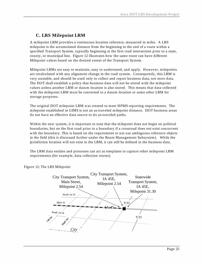
C. LRS Milepoint LRM A milepoint LRM provides a continuous location reference, measured in miles. A LRS milepoint is the accumulated distance from the beginning to the end of a route within a specified Transport System, typically beginning at the first road intersection prior to a state, county, or municipal line. Figure 12 illustrates how the same route can have different Milepoint values based on the desired extent of the Transport System. Milepoint LRMs are easy to maintain, easy to understand, and apply. However, milepoints are recalculated with any alignment change in the road system. Consequently, this LRM is very unstable, and should be used only to collect and report business data, not store data. The DOT shall establish a policy that business data will not be stored with the milepoint values unless another LRM or datum location is also stored. This means that data collected with the milepoint LRM must be converted to a datum location or some other LRM for storage purposes. The original DOT milepoint LRM was created to meet HPMS reporting requirements. The milepoint established in GIMS is not an as-traveled milepoint distance. DOT business areas do not have an effective data source to do as-traveled paths. Within the new system, it is important to note that the milepoint does not begin on political boundaries, but on the first road prior to a boundary if a crossroad does not exist concurrent with the boundary. This is based on the requirement to not use ambiguous reference objects in the field (this is discussed further under the Route Management Subsystem). While the jurisdiction location will not exist in the LRM, it can still be defined in the business data. The LRM data entities and processes can act as templates to capture other milepoint LRM requirements (for example, data collection routes).
Figure 12: The LRS Milepoint
IA 45
Y33
City
Main St
Maple A
ve
North 1st St
Oak Ave
South 1st St
Y33
City Transport System,Main Street,
Milepoint 2.54
StatewideTransport System,
IA 45E,Milepoint 31.30
City Transport System,IA 45E,
Milepoint 2.54
Logical Design Summary Document
Page 26
1. Process Given the existing data entities in the LRS, the LRS Milepoint LRM is completely derivable (no manual tasks). The milepoint reference method can be accommodated within the Route Management Subsystem as a derived attribute contained within the complex intersection table, System Route Link. For any transport system, the traversals can be built that will have a known link distance. The milepoints of that transport system are derived from the cumulative link distance of that system. The LRS Milepoint LRM data will be published, to make it accessible for use by other subsystems and to LRS users.
2. Data The LRM must be able to:
• Provide accumulated distance along as-traveled paths of Signed Routes. System Entity: System Route Link.
• Represent state, local, county, and regional extents; i.e., the milepoint is set to zero at desired extents. System Entity: Transport System and System Route Link.
• Provide the state of the milepoint at any given point in time or range in time. System Attributes: Establish and retire dates for System Route Link.
• Transform between this LRM and the datum. System Entities: System Route Link, Transport Link, and Transport Link Sequence.
3. Technology The LRM data is tabular-like and therefore, it can be stored in Oracle. No special tools are required to calculate the LRM accumulated distance, as it is a basic mathematical computation.
4. Organization The LRM does not require any specialized skills that are not already addressed by the Route Management Subsystem.
5. Remaining Challenges If a significant difference in the distance between opposite directions of travel along a route warrant calculating bi-directional milepoints, it will be necessary to create non-cardinal direction (South and West) System Route Links on bi-directional roadways.
Iowa DOT LRS Development Project
Page 27
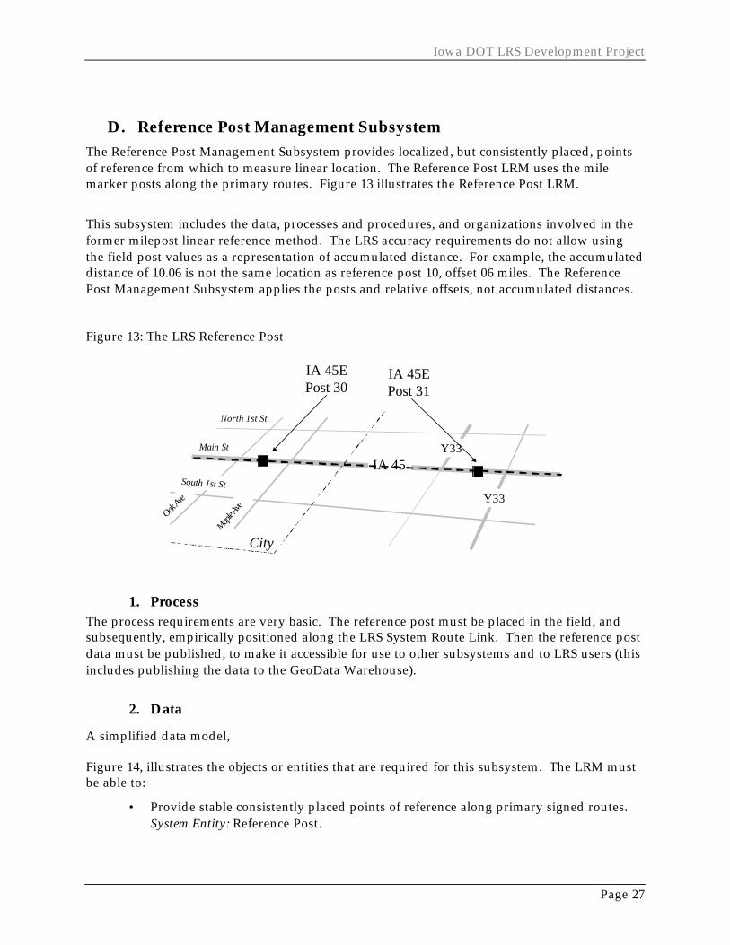
D. Reference Post Management Subsystem The Reference Post Management Subsystem provides localized, but consistently placed, points of reference from which to measure linear location. The Reference Post LRM uses the mile marker posts along the primary routes. Figure 13 illustrates the Reference Post LRM.
This subsystem includes the data, processes and procedures, and organizations involved in the former milepost linear reference method. The LRS accuracy requirements do not allow using the field post values as a representation of accumulated distance. For example, the accumulated distance of 10.06 is not the same location as reference post 10, offset 06 miles. The Reference Post Management Subsystem applies the posts and relative offsets, not accumulated distances.
Figure 13: The LRS Reference Post
IA 45
Y33
City
Main St
Maple A
ve
North 1st St
Oak Ave
South 1st St
Y33
IA 45EPost 30
IA 45EPost 31
1. Process The process requirements are very basic. The reference post must be placed in the field, and subsequently, empirically positioned along the LRS System Route Link. Then the reference post data must be published, to make it accessible for use to other subsystems and to LRS users (this includes publishing the data to the GeoData Warehouse).
2. Data
A simplified data model,
Figure 14, illustrates the objects or entities that are required for this subsystem. The LRM must be able to:
• Provide stable consistently placed points of reference along primary signed routes. System Entity: Reference Post.

Logical Design Summary Document
Page 28
• Provide the state of the reference post at any given point in time or range in time. System Attributes: Establish and retire dates for Reference Post.
• Transform between this LRM and the datum. System Entities: Reference Post, System Route Link, Transport Link, and Transport Link Sequence (see the Route Management Subsystem for these last two entities).
Figure 14: Reference Post Data Model
System Route Link Reference Post
Signed Route
State Signed Route
3. Technology The reference posts are currently maintained in the field and in a database at DOT. The database uses videolog van technology to produce route and x/y locations of the reference posts, and these data are stored in a SAS database. The pilot phase of this project may experiment with using the Coordinate Route LRM to transform the videolog positions to a System Route Link position. Most likely, the Reference Post Management System data will migrate to Oracle and use GeoMedia for graphical display.
4. Organization The following table lists specialized skills for the Reference Post Management Subsystem roles. For a complete list of the general knowledge, skills, and responsibilities of these roles, see the section Operational Architecture Requirements.
Table 4: Reference Post Subsystem Manager & Staff Roles
Subsystem Manager Subsystem Support Staff Knowledge and Skills: • Current LRM field and office
practices.
Knowledge and Skills: • Current LRM field and office
practices. Responsibilities: • Work with the Field Maintenance
managers and staff.
Responsibilities: • Work with the Field Maintenance
staff.

Iowa DOT LRS Development Project
Page 29
E. Stationing Management Subsystem The Stationing Management Subsystem will better support and manage an existing LRM at Iowa DOT. It will provide the ability to integrate data referenced to roadway engineering stationing with data referenced to other LRMs. The Subsystem includes the ability to link data that has stationing from another project in the same location, and to convert stationing to and from other LRMs. The stationing LRM only approximates the linear locations of station posts and business data locations. It would be cost-prohibitive to either reference the actual station posts to highly accurate locations or to bring the entire LRS (the datum) up to the accuracy of stationing. However, the LRM design minimizes error. Figure 15 helps illustrate how this is done. The stationing LRM is composed of project sections. Project sections are defined by the beginning and end of an improvement project, where cross stationing exists, and in situations where station equations exist. Each project section has a beginning station value and ending station value. These values will be used to interpolate positions of station posts or business objects along the project section (similar to address ranges along city blocks). The smaller the project section, the more accurate the position of a station post or business object. Each new road improvement project, even if in the same location, would have a new set of project sections and stationing from/to pairs.
Figure 15: The LRS Stationing
IA 45
Y33
City
Main St
Maple A
ve
North 1st St
Oak Av
e
South 1st St
Y33
ProjectSectionNode
ProjectSection Station
EquationStation
Post
1. Process The Iowa DOT currently uses project stationing to reference the locations of a variety of business data. However, only the field maintenance of station posts and pavement stamps have existing, formalized maintenance practices. While the need has existed for some time, this project is formalizing the requirement to link the stationing posts and markers to other DOT
Logical Design Summary Document
Page 30
LRMs. The process requirements for this subsystem are to maintain the field references and to maintain the link to the other LRMs. These requirements are briefly described here. Station posts and pavement stamps must be placed in the field. In the office, the project section location is determined and subsequently correlated with the corresponding anchor sections for that stretch of roadway. Most LRMs in the LRS are placed along a route, but stations are not route-dependent (they are project-dependent). Once the project sections are placed, the station posts linear locations are placed along the project sections (using the interpolation approach described above). Finally, the stationing subsystem data is published to make it accessible for use to other subsystems and to LRS users. The Needs Assessment indicated that the current procedures for placing station posts and markers in the field vary in method and rigor across the six DOT Districts. While making such business improvements is outside the scope of this project, this system will begin to help DOT standardize these practices.
2. Data A simplified data model, Figure 16, illustrates the objects or entities that are required for this subsystem. The LRM must be able to:
• Uniquely identify stationing locations across the state. System Entities: Project Section, Improvement Project.
• Provide stable, equally spaced points of reference along an improvement project. System Entities: Project Section, Project Sequence.
• Process through station equations. System Entities: Project Section, Project Section Node.
• Provide the state of the project section at any given point in time or range in time. System Attributes: Establish and retire dates for the Improvement Project.
• Transform between this LRM and the datum. System Entities: Project Section, Project Section Sequence, Project Section Node, and Project Section Offset.
To uniquely identify station locations, stationing is directly coupled to a particular improvement project at a specific point in time. Therefore, the project ID is a critical component of the Stationing Subsystem and for the business data that is linked to stationing. The sources of stationing can come from as-let plans because the stationing does not change in the as-builts (if stations change in construction, the plan goes back to design).

Iowa DOT LRS Development Project
Page 31
Figure 16: Stationing Data Model
Project Section
Improvement Project
Project Section Node
Anchor Section
Station Post
ProjectSection
Sequence
Project SectionNode Offset
3. Technology The existing field component of this subsystem uses technology that will not be described here. Positioning the project sections along the datum will require two different technology sets. First, DOT’s roadway design software (GeoPak) may be required to initially create the project sections. The strategy is for DOT design functions to provide digital forms of as-let design to the Subsystem maintenance tasks. Second, Oracle and a GeoMedia Pro interface will be required to position the project sections along the datum and to publish the data.
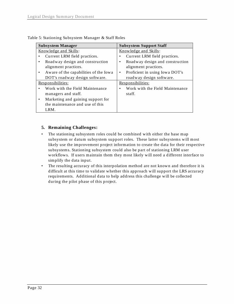
4. Organization The following table lists specialized skills for the Stationing Management Subsystem roles. For a complete list of the general knowledge, skills, and responsibilities of these roles, see the section Operational Architecture Requirements.
Logical Design Summary Document
Page 32
Table 5: Stationing Subsystem Manager & Staff Roles
Subsystem Manager Subsystem Support Staff Knowledge and Skills: • Current LRM field practices. • Roadway design and construction
alignment practices. • Aware of the capabilities of the Iowa
DOT’s roadway design software.
Knowledge and Skills: • Current LRM field practices. • Roadway design and construction
alignment practices. • Proficient in using Iowa DOT’s
roadway design software. Responsibilities: • Work with the Field Maintenance
managers and staff. • Marketing and gaining support for
the maintenance and use of this LRM.
Responsibilities: • Work with the Field Maintenance
staff.
5. Remaining Challenges: • The stationing subsystem roles could be combined with either the base map
subsystem or datum subsystem support roles. These latter subsystems will most likely use the improvement project information to create the data for their respective subsystems. Stationing subsystem could also be part of stationing LRM user workflows. If users maintain them they most likely will need a different interface to simplify the data input.
• The resulting accuracy of this interpolation method are not known and therefore it is difficult at this time to validate whether this approach will support the LRS accuracy requirements. Additional data to help address this challenge will be collected during the pilot phase of this project.
Iowa DOT LRS Development Project
Page 33
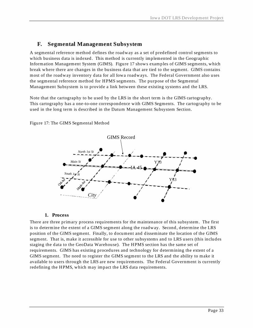
F. Segmental Management Subsystem A segmental reference method defines the roadway as a set of predefined control segments to which business data is indexed. This method is currently implemented in the Geographic Information Management System (GIMS). Figure 17 shows examples of GIMS segments, which break where there are changes in the business data that are tied to the segment. GIMS contains most of the roadway inventory data for all Iowa roadways. The Federal Government also uses the segmental reference method for HPMS segments. The purpose of the Segmental Management Subsystem is to provide a link between these existing systems and the LRS. Note that the cartography to be used by the LRS in the short term is the GIMS cartography. This cartography has a one-to-one correspondence with GIMS Segments. The cartography to be used in the long term is described in the Datum Management Subsystem Section.
Figure 17: The GIMS Segmental Method
IA 45
Y33
City
Main St
Maple A
ve
North 1st St
Oak Ave
South 1st St
Y33
GIMS Record
1. Process There are three primary process requirements for the maintenance of this subsystem. The first is to determine the extent of a GIMS segment along the roadway. Second, determine the LRS position of the GIMS segment. Finally, to document and disseminate the location of the GIMS segment. That is, make it accessible for use to other subsystems and to LRS users (this includes staging the data to the GeoData Warehouse). The HPMS section has the same set of requirements. GIMS has existing procedures and technology for determining the extent of a GIMS segment. The need to register the GIMS segment to the LRS and the ability to make it available to users through the LRS are new requirements. The Federal Government is currently redefining the HPMS, which may impact the LRS data requirements.

Logical Design Summary Document
Page 34
2. Data A simplified data model, Figure 18, illustrates the objects or entities that are required for this subsystem. The LRM must be able to:
• Provide the state of the segmental section at any given point in time or range in time. System Attributes: Establish and retire dates for the Control Section.
• Transform between this LRM and the datum. System Entities: Anchor Control Section, HPMS Control Section, and GIMS Control Section.
Figure 18: Segmental Data Model
HPMS Control Section
Anchor Control Section
Anchor Section
GIMS Control Section
3. Technology In 1999, the Iowa DOT began the process of migrating GIMS from an IDMS and MicroStation CAD data structure to an Oracle database interfaced through MicroStation. Because GIMS may be migrated from MicroStation to a GIS environment, an interface similar to the other LRS subsystems may need to be developed.
Iowa DOT LRS Development Project
Page 35
4. Organization The table below lists specialized skills for the Segmental Management Subsystem roles. For a complete list of the general knowledge, skills, and responsibilities of these roles, see the section, Operational Architecture Requirements.
Table 6: Segmental Subsystem Manager & Staff Roles
Subsystem Manager Subsystem Support Staff Knowledge and Skills: • Current GIMS maintenance
practices. • Direction of GIMS redesign and
development plans over the next few years.
Knowledge and Skills: • Current GIMS maintenance
practices.
Responsibilities: • Work with the Field Maintenance
managers and staff.
Responsibilities: • Work with the Field Maintenance
staff.
5. Remaining Challenges Specifically, the GIMS segments are based on the centerlines of multi-lane divided highways and a general point of intersection of complex intersections (like interchanges). The Office of Transportation Data will be adding new records, and modifying ramps, so that each roadway of a divided highway is more accurately represented. It is unclear how this will impact the centerline and point-of-intersection design, and subsequently, how the LRS will support the changes.
Logical Design Summary Document
Page 36
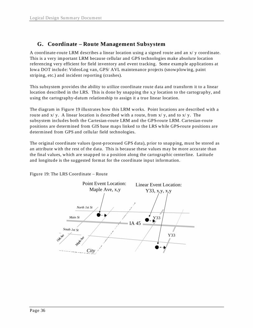
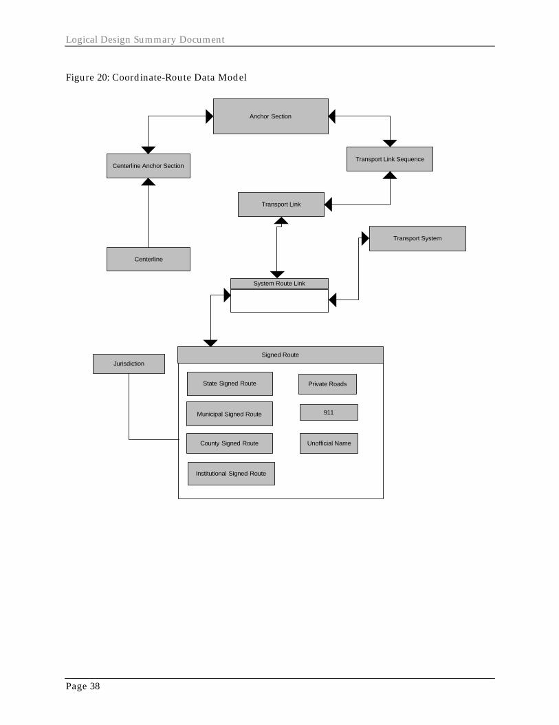
G. Coordinate – Route Management Subsystem A coordinate-route LRM describes a linear location using a signed route and an x/y coordinate. This is a very important LRM because cellular and GPS technologies make absolute location referencing very efficient for field inventory and event tracking. Some example applications at Iowa DOT include: VideoLog van, GPS/AVL maintenance projects (snowplowing, paint striping, etc.) and incident reporting (crashes). This subsystem provides the ability to utilize coordinate route data and transform it to a linear location described in the LRS. This is done by snapping the x,y location to the cartography, and using the cartography-datum relationship to assign it a true linear location. The diagram in Figure 19 illustrates how this LRM works. Point locations are described with a route and x/y. A linear location is described with a route, from x/y, and to x/y. The subsystem includes both the Cartesian-route LRM and the GPS-route LRM. Cartesian-route positions are determined from GIS base maps linked to the LRS while GPS-route positions are determined from GPS and cellular field technologies. The original coordinate values (post-processed GPS data), prior to snapping, must be stored as an attribute with the rest of the data. This is because these values may be more accurate than the final values, which are snapped to a position along the cartographic centerline. Latitude and longitude is the suggested format for the coordinate input information.
Figure 19: The LRS Coordinate – Route
IA 45
Y33
City
Main St
Maple A
ve
North 1st St
Oak Ave
South 1st St
Y33
Point Event Location: Maple Ave, x,y
Linear Event Location:Y33, x,y, x,y
Iowa DOT LRS Development Project
Page 37
1. Process This LRM has extensive process (and data) requirements. This LRM requires base map, datum, and route subsystem maintenance. Since the requirements of these three subsystems are either out of scope (base map) or exist elsewhere in this document they will not be repeated here. To “publish” this LRM requires publishing the data from the three different subsystems. The only process requirement not covered is spatial snapping. This requirement is driven by business data collection needs. Spatial snapping involves digitally attaching a business data point to the closest position along a cartographic representation of a roadway, based on a route name attribute that the point and cartography have in common.
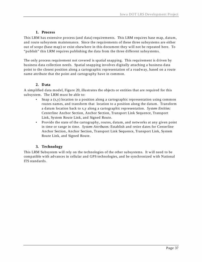
2. Data A simplified data model, Figure 20, illustrates the objects or entities that are required for this subsystem. The LRM must be able to:
• Snap a (x,y) location to a position along a cartographic representation using common routes names, and transform that location to a position along the datum. Transform a datum location back to x,y along a cartographic representation. System Entities: Centerline Anchor Section, Anchor Section, Transport Link Sequence, Transport Link, System Route Link, and Signed Route.
• Provide the state of the cartography, routes, datum, and networks at any given point in time or range in time. System Attributes: Establish and retire dates for Centerline Anchor Section, Anchor Section, Transport Link Sequence, Transport Link, System Route Link, and Signed Route.
3. Technology This LRM Subsystem will rely on the technologies of the other subsystems. It will need to be compatible with advances in cellular and GPS technologies, and be synchronized with National ITS standards.
Logical Design Summary Document
Page 38
Figure 20: Coordinate-Route Data Model
Jurisdiction
Transport Link
System Route Link
Transport System
Centerline Anchor Section
Anchor Section
Signed Route
State Signed Route
County Signed Route
Institutional Signed Route
Unofficial Name
Municipal Signed Route 911
Private Roads
Transport Link Sequence
Centerline
Iowa DOT LRS Development Project
Page 39
4. Organization The specialized skills required for the Coordinate-Route Subsystem Roles are identified in Table 7. For a complete list of the general knowledge, skills, and responsibilities of these roles, see Table 1. Table 7: Coordinate-Route Subsystem Manager & Staff Roles
Subsystem Manager Subsystem Support Staff Knowledge and Skills: • Current practice and trends in
absolute positioning technologies (GSP, cellular, etc.).
Knowledge and Skills: • Current practice and trends in
absolute positioning technologies (GSP, cellular, etc.).
Responsibilities: • Work to standardize usage among
business data collectors. • Educate on the need to interface with
the LRS. • Additional interface effort with the
Base Map, Datum, and Route Subsystem Managers and Staff.
Responsibilities: • Work with business data
collectors using this data. • Additional interface effort with
the Base Map, Datum, and Route Subsystem Staff.
5. Remaining Challenges Given the limited process and data requirements that are not covered by other LRS subsystems, it is recommended that this subsystem be incorporated into one of these other subsystems: Base Map, Datum, or Route.

Logical Design Summary Document
Page 40
H. Link-Node Management Subsystem The link-node LRM is being phased out as a supported LRM at Iowa DOT, so no redesign will occur. Existing crash data is being migrated to a coordinate route LRM. In the future, collected crash data will be recorded using route x/y coordinates in the LRS and be accessible via the Coordinate Route Subsystem.
Iowa DOT LRS Development Project
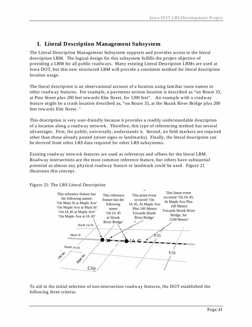
Page 41
I. Literal Description Management Subsystem The Literal Description Management Subsystem supports and provides access to the literal description LRM. The logical design for this subsystem fulfills the project objective of providing a LRM for all public roadways. Many existing Literal Description LRMs are used at Iowa DOT, but this new structured LRM will provide a consistent method for literal description location usage. The literal description is an observational account of a location using familiar route names or other roadway features. For example, a pavement section location is described as “on Route 33, at Pine Street plus 200 feet towards Elm Street, for 1200 feet”. An example with a roadway feature might be a crash location described as, “on Route 33, at the Skunk River Bridge plus 200 feet towards Elm Street. " This description is very user-friendly because it provides a readily understandable description of a location along a roadway network. Therefore, this type of referencing method has several advantages. First, the public, universally, understands it. Second, no field markers are required other than those already posted (street signs or landmarks). Finally, the literal description can be derived from other LRS data required for other LRS subsystems. Existing roadway network features are used as references and offsets for the literal LRM. Roadway intersections are the most common reference feature, but others have substantial potential as almost any physical roadway feature or landmark could be used. Figure 21 illustrates this concept.
Figure 21: The LRS Literal Description
IA 45
Y33
City
Main St
Maple A
ve
North 1st St
Oak Ave
South 1st St
Y33
Literal DescriptionThis reference feature has
the following names:‘On Main St at Maple Ave’‘On Maple Ave at Main St’‘On IA 45 at Maple Ave’‘On Maple Ave at IA 45’
This linear event occurred ‘On IA 45, At Maple Ave Plus
100 MetersTowards Skunk River
Bridge, for 1100 Meters’
This point event occurred ‘On
IA 45, At Maple AvePlus 100 MetersTowards Skunk
River Bridge’
This referencefeature has the
following name:
‘On IA 45 at Skunk
River Bridge’
To aid in the initial selection of non-intersection roadway features, the DOT established the following three criteria:
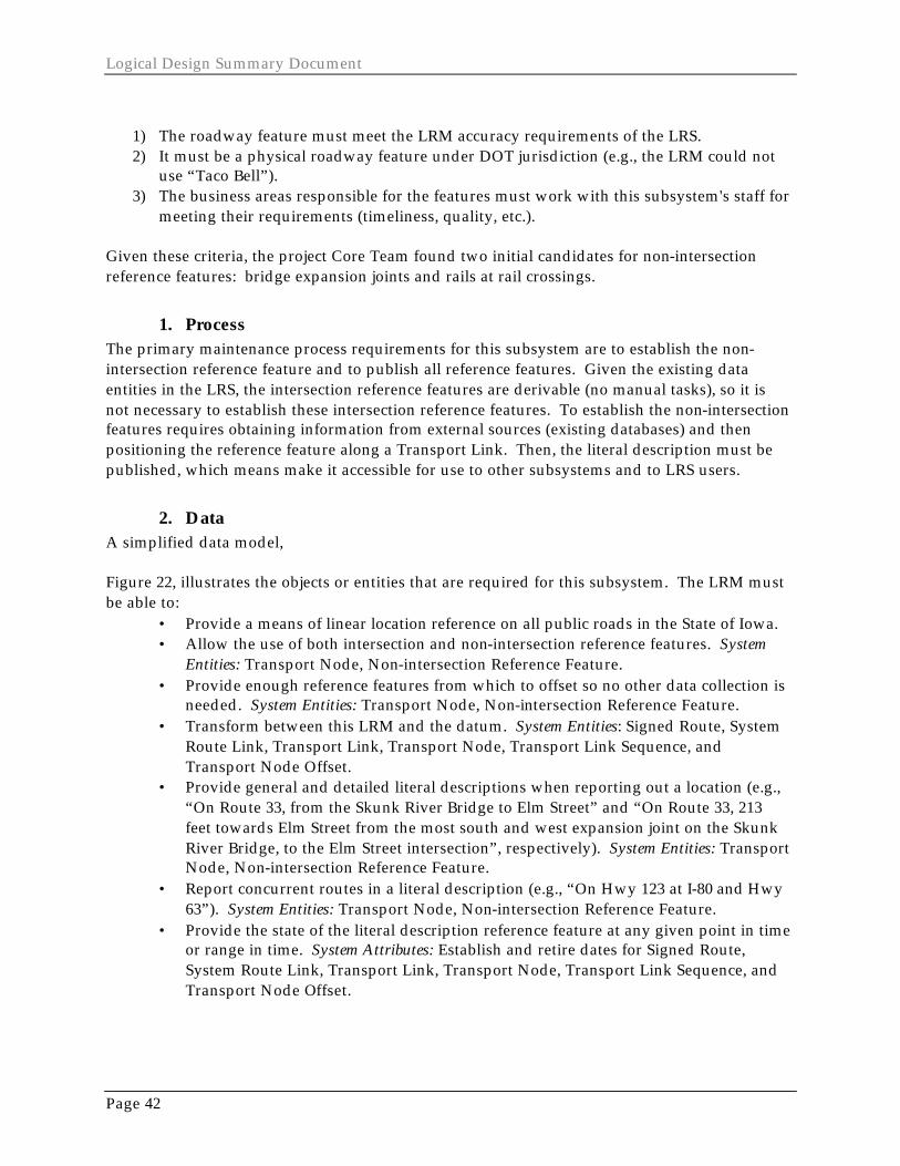
Logical Design Summary Document
Page 42
1) The roadway feature must meet the LRM accuracy requirements of the LRS. 2) It must be a physical roadway feature under DOT jurisdiction (e.g., the LRM could not
use “Taco Bell”). 3) The business areas responsible for the features must work with this subsystem's staff for
meeting their requirements (timeliness, quality, etc.).
Given these criteria, the project Core Team found two initial candidates for non-intersection reference features: bridge expansion joints and rails at rail crossings.
1. Process The primary maintenance process requirements for this subsystem are to establish the non-intersection reference feature and to publish all reference features. Given the existing data entities in the LRS, the intersection reference features are derivable (no manual tasks), so it is not necessary to establish these intersection reference features. To establish the non-intersection features requires obtaining information from external sources (existing databases) and then positioning the reference feature along a Transport Link. Then, the literal description must be published, which means make it accessible for use to other subsystems and to LRS users.
2. Data A simplified data model, Figure 22, illustrates the objects or entities that are required for this subsystem. The LRM must be able to:
• Provide a means of linear location reference on all public roads in the State of Iowa. • Allow the use of both intersection and non-intersection reference features. System
Entities: Transport Node, Non-intersection Reference Feature. • Provide enough reference features from which to offset so no other data collection is
needed. System Entities: Transport Node, Non-intersection Reference Feature. • Transform between this LRM and the datum. System Entities: Signed Route, System
Route Link, Transport Link, Transport Node, Transport Link Sequence, and Transport Node Offset.
• Provide general and detailed literal descriptions when reporting out a location (e.g., “On Route 33, from the Skunk River Bridge to Elm Street” and “On Route 33, 213 feet towards Elm Street from the most south and west expansion joint on the Skunk River Bridge, to the Elm Street intersection”, respectively). System Entities: Transport Node, Non-intersection Reference Feature.
• Report concurrent routes in a literal description (e.g., “On Hwy 123 at I-80 and Hwy 63”). System Entities: Transport Node, Non-intersection Reference Feature.
• Provide the state of the literal description reference feature at any given point in time or range in time. System Attributes: Establish and retire dates for Signed Route, System Route Link, Transport Link, Transport Node, Transport Link Sequence, and Transport Node Offset.
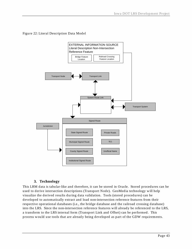
Iowa DOT LRS Development Project
Page 43
Figure 22: Literal Description Data Model
Jurisdiction
Transport Link
System Route Link
Transport System
Transport Node
Signed Route
State Signed Route
County Signed Route
Institutional Signed Route
Unofficial Name
Municipal Signed Route 911
Private Roads
EXTERNAL INFORMATION SOURCELiteral Description Non-IntersectionReference Feature
Bridge FeatureLocation
Railroad CrossingFeature Location
3. Technology This LRM data is tabular-like and therefore, it can be stored in Oracle. Stored procedures can be used to derive intersection descriptions (Transport Node). GeoMedia technology will help visualize the derived results during data validation. Tools (stored procedures) can be developed to automatically extract and load non-intersection reference features from their respective operational databases (i.e., the bridge database and the railroad crossing database) into the LRS. Since the non-intersection reference features will already be referenced to the LRS, a transform to the LRS internal form (Transport Link and Offset) can be performed. This process would use tools that are already being developed as part of the GDW requirements.
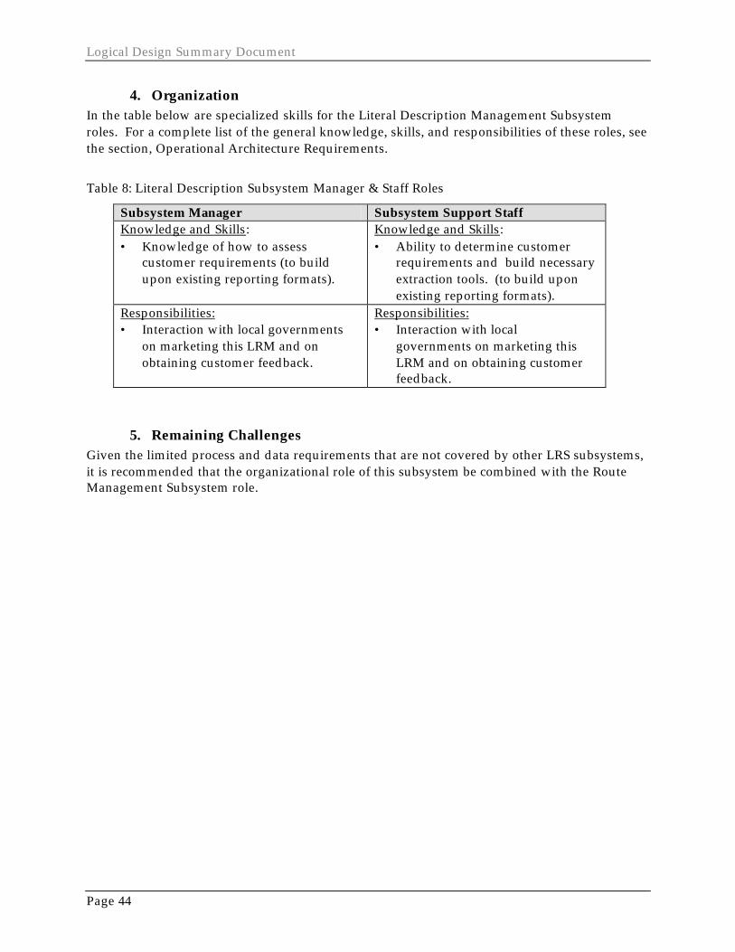
Logical Design Summary Document
Page 44
4. Organization In the table below are specialized skills for the Literal Description Management Subsystem roles. For a complete list of the general knowledge, skills, and responsibilities of these roles, see the section, Operational Architecture Requirements.
Table 8: Literal Description Subsystem Manager & Staff Roles
Subsystem Manager Subsystem Support Staff Knowledge and Skills: • Knowledge of how to assess
customer requirements (to build upon existing reporting formats).
Knowledge and Skills: • Ability to determine customer
requirements and build necessary extraction tools. (to build upon existing reporting formats).
Responsibilities: • Interaction with local governments
on marketing this LRM and on obtaining customer feedback.
Responsibilities: • Interaction with local
governments on marketing this LRM and on obtaining customer feedback.
5. Remaining Challenges Given the limited process and data requirements that are not covered by other LRS subsystems, it is recommended that the organizational role of this subsystem be combined with the Route Management Subsystem role.
Iowa DOT LRS Development Project
Page 45
J. LRS Management As with all systems, the entire LRS must be managed over time. This project focuses on four LRS Management functions: Business Operations, LRS Maintenance, LRS Administration, and LRS Monitoring. Requirements for the first function, Business Operations, are outside the scope of the project. However, some requirements are identified in order to provide examples of how to apply and test the LRS with real business data during the Project pilot phase. The LRS Maintenance requirements addressed here focus on those that initialize the LRS. All other maintenance requirements are presented in the individual subsystem sections of this report. These processes capture metadata ("data about data") about the LRS, its subsystems, and subsystem components. These processes also establish the transport systems that define the functionality, mode, extent and classification of the LRS. LRS Administration and monitoring functions are needed to ensure that the LRS meets customer expectations over time, and that information about the LRS is readily available to customers. LRS management will require a process that can gather and assess LRS customer expectations, determine system performance goals, monitor performance, determine whether performance goals have been met, and develop or improve LRS solutions to meet these performance goals. Only process and organizational requirements are provided for the administration and maintenance functions.
1. Process LRS Administration is composed of three process requirements. The first is to develop LRS policy. This process has three sub-process requirements. One is to determine the customer needs of the LRS. Another is to establish LRS objectives. Objectives must include goals, performance benchmarks and LRS policy. Last, LRS standards are then determined and shared with subsystem maintainers and LRS users. The second LRS Administration process requirement is to develop the LRS itself. The process includes four sub-processes. One is to develop an LRS architecture. This includes developing conceptual, logical, and physical architectures. Another is to develop or redesign the LRS or its subsystems by analyzing, designing, constructing, and testing a new LRS solution. Yet another sub-process is to develop interfaces to the existing business systems at the DOT. Finally, the LRS is deployed. The third LRS Administration process requirement is LRS staffing. This means assigning staff to, and training them on, LRS management, maintenance, and operations. LRS Management includes the function of maintaining location references. This function has been thoroughly outlined in the individual subsystem sections of this report. One process not discussed elsewhere, but required by all subsystems, is “Initialize LRS” for each subsystem component. Again, a subsystem component is a logical grouping of subsystem entities. An example component is the network component in the Route Management Subsystem. The

Logical Design Summary Document
Page 46
network is composed of the following entities: Transport Link, Transport Node, Node State, Link State, Transport Node Offset, and Transport Link Sequence. The initialize process requires that LRS controls and parameters be established for each LRS component. To establish controls means to set and document LRS responsibilities, authority, and access permissions. To establish parameters means to set the global parameters, units of measure and other system wide metadata for the LRS driven by the LRS component. Finally, the initialize process requires that a Transport System for the LRS be established. A Transport System is a particular view of the transportation network based on functionality, mode, extent, and classification. Business Operations is another primary function of LRS Management. In the Logical Design Technical Document these operations are called Location Reference Operations. These are process requirements that business areas must meet to apply the LRS to their business data. These processes are outside the scope of the project. However, the Logical Design Technical Document outlines these basic requirements for selected business areas. These requirements include determining a business object and event location in the field and positioning the location with respect to a LRS LRM. The requirement also includes publishing the business data and location, which means make it accessible for use to other business areas (this includes publishing the data to the GeoData Warehouse). The final LRS Management function is LRS monitoring. LRS monitoring includes designing and conducting quality audits regarding data quality, service, cost, and time. Audits should be required for both field and database practices. These qualities should be published. Finally, the qualities should be evaluated, based on performance goals. Once analyzed, LRS Administration processes would initiate again.
2. Data Only the data requirements for transport system and metadata were defined. For a given transport system, the LRS must be driven by the need to support DOT requirements based on:
• The mode or multiple modes required for a business system: roadway, railway, pedestrian, telecommuting, etc. System Entities: Transport System.
• A particular geographic extent (City of Ames), functionality (asset management, transit management, snowplow operations), and by jurisdiction (roadways managed by the county, city, or state). System Entities: Transport System.
The LRS must also provide metadata information. Figure 23, a simplified data model, illustrates the objects or entities that are required for LRS metadata. The LRS must provide information about:
• DOT policies on the use and management of the LRS and its components (external to LRS data design).
• Who needs access to the LRS components, and what kind of access. System Entities: LRS Contact, LRS Component Relationship).
• Contacts for more information regarding LRS components. System Entities: LRS Contact, LRS Component Relationship.

Iowa DOT LRS Development Project
Page 47
• Who needs to be informed about changes to LRS components and their associated data? System Entities: LRS Contact, LRS Component Relationship.
• LRS component access mechanisms: standards on interfacing to a subsystem or obtaining remote copies of the data. System Entity: LRS Component.
• LRS component data qualities: lineage, logical consistency, completeness, relative and absolute accuracy, all spatial dimensions. System Entity: LRS Component.
• LRS component parameters: underlying reference systems and measurement units. System Entity: System-wide Metadata.
Figure 23: LRS Component Data Model
System-Wide Metadata
LRS ContactLRS Component
LRS Component Relationship
LRS ComponentManager
LRS ComponentSupport Person
LRS Customer
EXTERNAL INFORMATION SOURCEDOT Policies and Procedures
3. Technology LRS Management is not considered a LRS subsystem, but part of every subsystem. The focus for the project is primarily on the Transport System and the LRS metadata. It is envisioned that Transport System would be stored and manipulated in Oracle. Most LRS Component information will be stored in Oracle as well. Some component information will be stored in formats generated by existing metadata tools at DOT. The Oracle database would provide pointers to this information.

Logical Design Summary Document
Page 48
4. Organization In the other sections of the document, the organizational requirements focused on LRS subsystems. LRS Management organizational requirements are those that span across subsystems. Figure 24 illustrates the additional roles required for LRS Management and the interactions of these roles. LRS Management roles include LRS Sponsor, LRS Manager, LRS Board of Directors, and the LRS Operations Work Team. Roles already defined are the LRS Subsystem Manager and the LRS Support Staff. The overall organizational architecture is composed of two key bodies: the LRS Board of Directors and the LRS Operations Work Team. The Board of Directors makes strategic policy and resource decisions for the LRS, driven by the DOT divisions’ interests in making the LRS a success. The Board is composed of key managers from the various divisions. The Work Team is the tactical and implementation planning body of the LRS. They are ultimately responsible for LRS Management. The Work Team is composed of the GDW and LRS subsystem managers. Two roles key to LRS success are the LRS Manager and the LRS Sponsor. These two will chair the Work Team and Board, respectively. They will guide the direction of the LRS and ensure that the LRS vision, mission, and timely objectives are upheld.
Figure 24: LRS Organizational Architecture
LRS Operations Work TeamDatum
SubsystemManager
GDWManager
o o oRoute
SubsystemManager
LRS Manager
DOT DivisionsLRS "Board of Directors"
DatumSubsystem
Support Staff
GDW SupportStaff
LRSSupport Staff o o o
RouteSubsystem
Support Staff
DivRep
DivRep
DivRep
DivRep
DivRep
LRS Sponsor
LRS Standards,LRS Objectives Same as
Datum
Performance ReportingProject Progress
Budget IssuesPolicy Recommendation
DOT Objectives & StrategiesResources
DOT Strategic DirectionBudget ImplicationsLRS Performance
LRS PolicyResources
PerformanceReporting,
Issues
Same asDatum
Same asDatum
Same asDatum

Iowa DOT LRS Development Project
Page 49
The following tables outline the general knowledge, skills, and responsibilities for the four roles defined here. The skills of the Subsystem Manager and Support Staff are outlined in each subsystem section of this document.
Members of the LRS Work Team allocate approved resources, improve the LRS design, develop and implement standards, draft policies for the Board, report LRS performance, resolve issues, and request resources.
Table 9: LRS Component Sponsor and Board Roles
LRS Sponsor LRS Board of Directors Knowledge and Skills: • Budget Management. • Leadership. • Communication. • Business Process and Quality
Improvement. • General understanding of the
benefits and costs of the Iowa DOT LRS.
• Transportation Asset Management (ITS desired).
• Policy decision-making. • Very strong interest in the
implementation and management of the LRS.
Knowledge and Skills: • Budget Management. • Leadership. • Communication. • Business Process and Quality
Improvement. • General understanding of the
benefits and costs of the Iowa DOT LRS.
• Transportation Asset Management .
• Policy decision-making . • Division LRS needs, objectives,
priorities. • Strong interest in the
implementation and management of the LRS.
Responsibilities: • Focus on making LRS a success. • A Division or Bureau level manager
in the organization. • Markets LRS among DOT senior
management, key DOT customers and suppliers, key DOT stakeholders.
• Schedules and chairs the LRS Board of Directors.
• Helps identify and removes barriers to LRS Success.
• Available to the LRS Manager for LRS planning, issues resolution, etc..
• Acts as LRS Board of Director Member.
Responsibilities: • Focus on making LRS a success. • Performs duties as assigned. • Applies DOT objectives and goals
for LRS decision-making. • Applies division objectives and
goals for LRS decision-making. • Applies LRS performance review
to LRS decision-making. • Market LRS within the Division,
Division customers, suppliers, and stakeholders.
• Approves LRS Policy and Standards.
• Approves proposed LRS improvement recommendations.

Logical Design Summary Document
Page 50
Table 10: LRS Manager & Staff Roles
LRS Manager LRS Operations Work Team Knowledge and Skills: • Budget management. • Leadership. • Communication. • Business process and quality
Improvement. • Detailed understanding of the
benefits and costs of the Iowa DOT LRS.
• Transportation Asset Management (ITS desired).
• Policy and standards development . • Very strong interest in the
implementation and management of the LRS.
Knowledge and Skills: • Budget management. • Leadership. • Communication. • Business process and quality
improvement. • Detailed understanding of the
benefits and costs of the Iowa DOT LRS.
• Transportation Asset Management (ITS desired).
• Policy and standards development.
• Very strong interest in the implementation and management of the LRS.
Responsibilities: • Focus on making LRS a success. • A Section or unit supervisor,
preferably one of the LRS subsystem managers.
• Markets LRS among DOT management, DOT customers and suppliers, DOT stakeholders.
• Schedules and chairs the LRS Operations Work Team meetings.
• Helps identify and removes barriers to LRS Success.
• Leads LRS strategic and tactical planning, issues resolution, etc..
• Acts as LRS Operations Work Team member.
Responsibilities: • Focus on making LRS a success. • Performs duties as assigned. • Prioritizes LRS resources and
improvements. • Resolves LRS conflicts and issues. • Markets entire LRS among
subsystem suppliers and customers.
5. Remaining Challenges • There may be a need to separate operational attributes (like units of measure) from
system definition attributes (like component manager). • The datum and other linear objects are most likely spatial constructs. If so, the LRS
falls under NSDI constraints and the impacts of these constraints on the LRS design should be evaluated.
Iowa DOT LRS Development Project
Page 51
VI. DECISION SUPPORT ARCHITECTURE REQUIREMENTS LRS-based decision support will be an important part of the GeoData Warehouse (GDW), which already exists at Iowa DOT. An overview of the GDW and its processes is provided at the beginning of this document in the Conceptual Design Overview. Basically, the GDW is the data environment where DOT employees can access and apply a myriad of DOT data. The standard DOT interface to the GDW is called the Coordinated Transportation Analysis and Management System (CTAMS). The primary data content of the GDW, historically, has been spatially enabled data (map locations). However, this is not a requirement of GDW data. This project is required to design access for analysis of linear-referenced data. That is, the use of the Operational LRS Architecture will become part of the GDW. The primary objectives of applying linear locations in GDW are to:
• Transform between the Iowa DOT standard LRMs and base cartography, • Validate the LRS and the location quality of business data, • Provide both ad hoc and predefined data integration and analysis for linear-
referenced data, and • Provide an environment to integrate linear data with other spatially enabled data.
This section of the LRS Logical Design captures the LRS requirements for these objectives.
1. Process The Conceptual Design outlined the overall GDW processes. Table 11 lists and describes these processes, as well as potential organizational and technology solutions to support these processes. The project will focus on defining requirements for LRS-related processes within these GDW processes. These LRS-related processes are GDW data administration (under Overall GDW Management), data staging (under Staging Tools Management, LRS Data Staging, and Business Data Staging), and linear integration and analysis (under User Tools Management).
a) GDW Data Administration GDW data administration includes process requirements that establish and enforce database standards, monitor disk capacity, manage access to LRS data, and help GDW users define LRS-related GDW databases. By definition, the GDW does not allow data editing as data editing is performed in the operational data environment. LRS security will not allow the GDW users to have direct read access to the LRS operational data and queries may only occur on staged GDW/LRS data. In addition, GDW users will not be able to store their ad hoc query or analysis results in the GDW. However, GDW users must be able to make their results available via GDW interfaces to other potential users (this will require the creator to store the data in an accessible location and
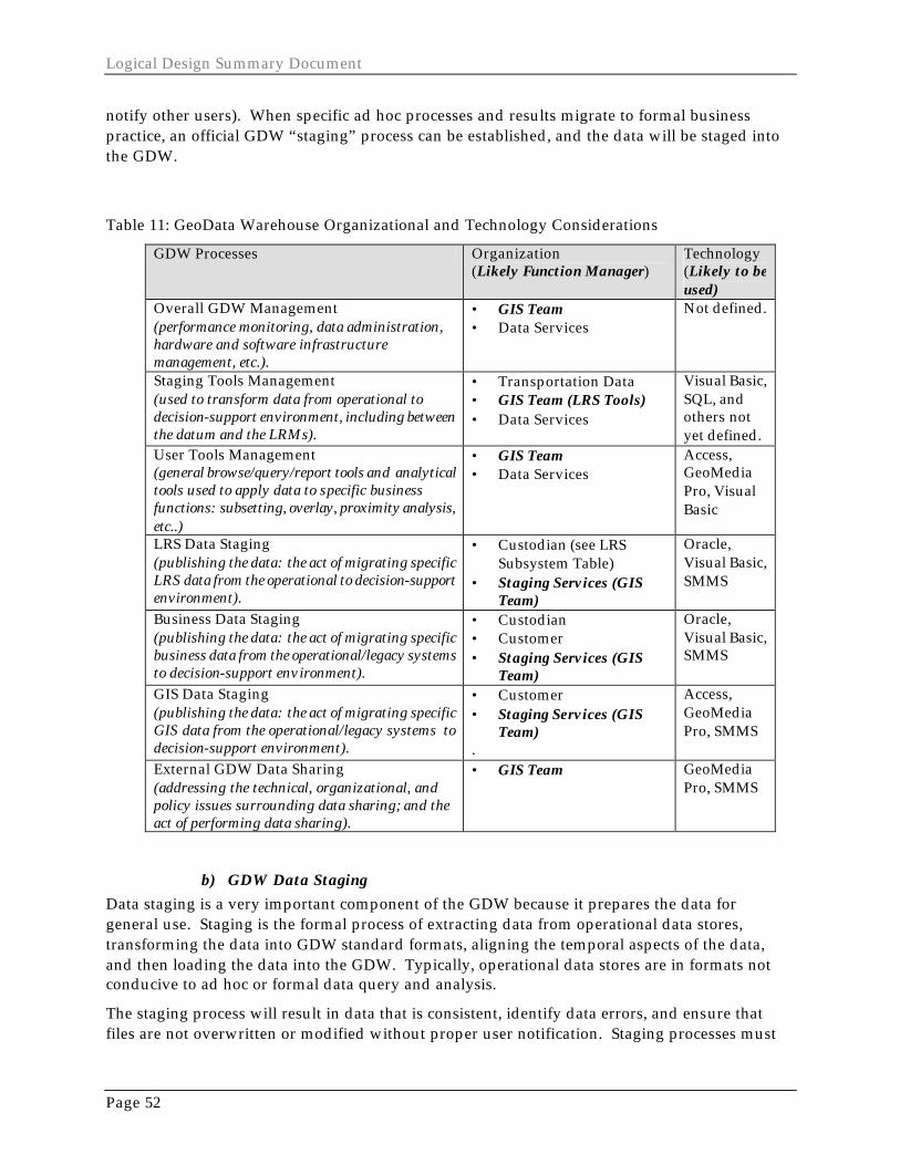
Logical Design Summary Document
Page 52
notify other users). When specific ad hoc processes and results migrate to formal business practice, an official GDW “staging” process can be established, and the data will be staged into the GDW.
Table 11: GeoData Warehouse Organizational and Technology Considerations
GDW Processes Organization (Likely Function Manager)
Technology (Likely to be used)
Overall GDW Management (performance monitoring, data administration, hardware and software infrastructure management, etc.).
• GIS Team • Data Services
Not defined.
Staging Tools Management (used to transform data from operational to decision-support environment, including between the datum and the LRMs).
• Transportation Data • GIS Team (LRS Tools) • Data Services
Visual Basic, SQL, and others not yet defined.
User Tools Management (general browse/query/report tools and analytical tools used to apply data to specific business functions: subsetting, overlay, proximity analysis, etc..)
• GIS Team • Data Services
Access, GeoMedia Pro, Visual Basic
LRS Data Staging (publishing the data: the act of migrating specific LRS data from the operational to decision-support environment).
• Custodian (see LRS Subsystem Table)
• Staging Services (GIS Team)
Oracle, Visual Basic, SMMS
Business Data Staging (publishing the data: the act of migrating specific business data from the operational/legacy systems to decision-support environment).
• Custodian • Customer • Staging Services (GIS
Team)
Oracle, Visual Basic, SMMS
GIS Data Staging (publishing the data: the act of migrating specific GIS data from the operational/legacy systems to decision-support environment).
• Customer • Staging Services (GIS
Team) .
Access, GeoMedia Pro, SMMS
External GDW Data Sharing (addressing the technical, organizational, and policy issues surrounding data sharing; and the act of performing data sharing).
• GIS Team GeoMedia Pro, SMMS
b) GDW Data Staging Data staging is a very important component of the GDW because it prepares the data for general use. Staging is the formal process of extracting data from operational data stores, transforming the data into GDW standard formats, aligning the temporal aspects of the data, and then loading the data into the GDW. Typically, operational data stores are in formats not conducive to ad hoc or formal data query and analysis.
The staging process will result in data that is consistent, identify data errors, and ensure that files are not overwritten or modified without proper user notification. Staging processes must

Iowa DOT LRS Development Project
Page 53
also refresh the GDW metadata so users are aware of the new GDW data. However, the GDW must allow for different options when staging LRS and business data updates to the GDW. One option is that the staging process should be able to completely replace a table or file in the current GDW database. One example of replacing data might be the current construction information that the public would query. Another option is that the staging process should be able to append and remove records from the current GDW database. This is useful for large multi-year databases, like the crash data. In the GDW, the ability to store queries should be provided to allow different views of the data (e.g., annual crash views). Finally, the staging process must be able to version the GDW database for historic and temporal database comparisons as well as safeguarding past scenarios of the DOT data. An example is loading pavement section databases over several years for comparison and analysis.
c) Underlying GDW Linear Processing Services. These services are the most important process requirements of this project. It is these services, along with the LRS data, that is the entire purpose for this project. There are several key services: Linear Transform. The GDW must provide the ability to transform linear data, via the datum, to any standard LRM and to a spatial reference in GIS space. The GDW also must provide the ability to transform linear data to a location within the same LRM but between different descriptions of the same location (this capability must be possible for LRS milepoint, reference post, literal description, and project stationing). A user must be able to perform a transform for one location interactively, an entire dataset interactively, or an entire dataset in batch. The transform services details will be invisible to GDW users because formal applications and user interfaces will call the necessary functions. The staging process will also use these transform services.
Linear Integration. The GDW must be capable of integrating linear data, using the linear datum. The results of integration are new segments based on the collective overlay of two linear data sets. The required options for the linear overlay include: 1) union - resulting segments exist where ever at least one input data set exists, 2) intersect - resulting segments exist only where all input data sets share common location, and 3) difference – resulting segments exist only where input data sets do not share a common location with a reference data set. The GDW must be able to support linear event/linear event and linear event/point event integration. A user must be able to perform the overlay analyses on an entire dataset interactively, or initiate the dataset change through batch processing. Linear Analysis. The GDW must support dynamic segmentation, linear aggregation, linear proximity, and network analysis. Dynamic segmentation is the generation of linear referenced data along cartography. Linear aggregation combines contiguous segments with similar attributes into one segment. Linear proximity creates Thiessen-like linear objects from disaggregated linear and point events. Finally, network analysis includes path-finding and allocation functions. For all of these, the user must have the option of displaying results to the screen or saving the result to disk for later access.
Logical Design Summary Document
Page 54
GDW User Interface. Business data that is referenced to the LRS must be accessible and displayed by either a tabular or graphic (GIS) interface. The interface to specific LRS processing services must be transparent to the user by using command structures and GUI design that blend in with the standard GDW GUI. Finally, when accessing LRS data and tools, the user must be able to use the standard query commands (both tabular and graphic) that are, currently, part of the current GDW.
2. Data Data requirements for the GDW are driven primarily by the uses of the data. Data requirements of this project will depend on the benchmarks that are chosen for the pilot phase. However, there are some general requirements. The GDW must:
• Provide a graphical context to business data. For example, the user must be able to graphically display bridge data.
• Provide ad hoc queries into business data. For example, the user must be able to query the bridge characteristics for a single bridge or a subset of bridges.
• Provide a graphical context to LRS data. For example, the user must be able to graphically display transport links and nodes, but most likely does not need to portray anchor point monuments.
• Provide ad hoc queries into LRS data. For example, the user must be able to query the names of the routes that traverse a given point, but most likely does not need to query the Node State data.
• Be able to easily determine what is past, current, or proposed for both LRS and business data.
For all data, the GDW must provide users access to GDW metadata to determine basic information about the data availability.
3. Technology The DOT currently does not have any formal technologies established for GDW Data Administration. Oracle, GeoMedia, and system security (Microsoft Windows NT) will assist in managing access to GDW and LRS data. The underlying linear processing services will most likely be written in Java and PL/SQL. Those services will be accessible to the GDW user interface and application calls. The GDW User Interface will be the standard GeoMedia technology with Visual Basic enhancements for the LRS. LRS data staging will most likely apply Oracle and PL/SQL or Java based programming. Business data staging will apply the appropriate technologies given the data source environment. Data staging will also require updating the CTAMS metadata and putting data into the Spatial Metadata Management System (SMMS), a computer program used by DOT that allows FGDC compliant metadata to be put into HTML format so it can be accessed via the web.
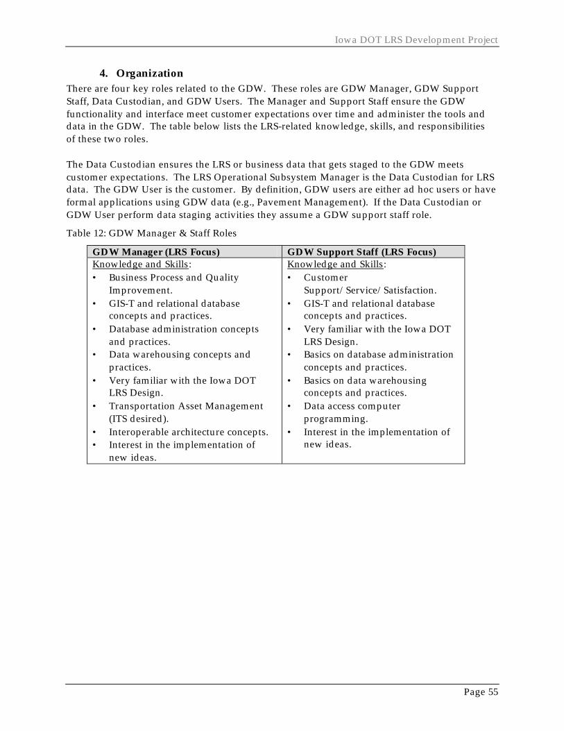
Iowa DOT LRS Development Project
Page 55
4. Organization There are four key roles related to the GDW. These roles are GDW Manager, GDW Support Staff, Data Custodian, and GDW Users. The Manager and Support Staff ensure the GDW functionality and interface meet customer expectations over time and administer the tools and data in the GDW. The table below lists the LRS-related knowledge, skills, and responsibilities of these two roles. The Data Custodian ensures the LRS or business data that gets staged to the GDW meets customer expectations. The LRS Operational Subsystem Manager is the Data Custodian for LRS data. The GDW User is the customer. By definition, GDW users are either ad hoc users or have formal applications using GDW data (e.g., Pavement Management). If the Data Custodian or GDW User perform data staging activities they assume a GDW support staff role.
Table 12: GDW Manager & Staff Roles
GDW Manager (LRS Focus) GDW Support Staff (LRS Focus) Knowledge and Skills: • Business Process and Quality
Improvement. • GIS-T and relational database
concepts and practices. • Database administration concepts
and practices. • Data warehousing concepts and
practices. • Very familiar with the Iowa DOT
LRS Design. • Transportation Asset Management
(ITS desired). • Interoperable architecture concepts. • Interest in the implementation of
new ideas.
Knowledge and Skills: • Customer
Support/Service/Satisfaction. • GIS-T and relational database
concepts and practices. • Very familiar with the Iowa DOT
LRS Design. • Basics on database administration
concepts and practices. • Basics on data warehousing
concepts and practices. • Data access computer
programming. • Interest in the implementation of
new ideas.

Logical Design Summary Document
Page 56
GDW Manager (LRS Focus) GDW Support Staff (LRS Focus) Responsibilities: • Data administration. • Performance monitoring. • Marketing GDW LRS capability and
services. • Ensuring GDW LRS capability meets
supplier (Custodian) and customer expectations (content, quality, service, timeliness, etc.) via performance tracking and business improvement.
• Represents the GDW in LRS policy, standards, GDW interface management, and LRS direction as member of the LRS Operations Work Team.
• Remains abreast of the needs and changes in the LRS subsystems.
Responsibilities: • Perform processes outlined for the
GDW. • Customer Support (other LRS
subsystem staff and business users).
• Performance reporting. • Issue identification and resolution. • GDW improvement. • Metadata maintenance. • Develop staging procedures and
computer programs. • Stage data to the GDW: perform
extract, transform the data, and load the data.
5. Remaining Challenges In the initial implementation of the GDW, the GDW Manager will perform linear-based data staging with assistance from the LRS custodians. It is undetermined when custodians and advanced users will begin to perform data staging.

Iowa DOT LRS Development Project
Page 57
VII. CONCLUSION During the requirements analysis and documentation, the project team discovered changes to the Conceptual LRS operational architecture. The diagram in Figure 25 illustrates those conceptual design modifications. These changes include collapsing subsystems, removing subsystems, and changing the linkages between the subsystems. The following list summarizes these changes.
• The LRS Milepoint LRM is now a subsidiary component of the Route Management Subsystem.
• Not all LRMs are linked to the Route Management Subsystem. • The Coordinate-Route LRM is process-oriented and leverages the data existing in the
Route Management Subsystem and the Base Map Management Subsystem. • The Literal Description LRM, although remaining separate, is primarily composed of
data existing within the Route Management Subsystem. • The Stationing LRM and Segmental LRM will interface directly with the datum. • The Link/Node LRM is not part of the design because it is being phased out. In the
interim, the historical data linked to the Link/Node will be accessible through the Segmental LRM or coordinate route LRM.
Figure 25: Logical Design Operational Model
SpatialString
The LinearReferenceSystem
Operational System
Business EventManagement
Systems
DatumManagementSubsystem
Base MapManagement
System
RouteManagementSubsystem
ReferencePost
ManagementSubsystem
LiteralDescription
ManagementSubsystem
Coordinate-Route
ManagementSubsystem
StationingManagementSubsystem
SegmentalManagementSubsystem
Link-NodeManagementSubsystem
BusinessEvents Business
EventsBusinessEvents
BusinessEvents Business
EventsBusiness
Events
Posted RouteMilepoint
LRM
LRS ComponentInformation
Logical Design Summary Document
Page 58
Within the scope of this project, the LRS Logical Design has six key LRS functions. They are: 1. LRS Administration – For the operational architecture this includes performing
customer assessments, setting LRS performance goals, and performing business system improvements. For the GDW this includes data administration.
2. LRS Maintenance – For the operational architecture this includes field operations to place LRS components in the field and office operations to position LRS components relative to each other in the database.
3. LRS Operations – For the operational architecture, this means the same as the LRS maintenance, which includes some LRS components. However, it also includes some business data to provide a template of requirements for interfacing redesigned business systems to the LRS.
4. LRS Monitoring – For the operational architecture this includes performance tracking and analysis.
5. GDW Staging – For the GDW architecture, this includes “publishing” LRS and business data to readily usable and standard access formats.
6. GDW Data Integration and Analysis – For the GDW architecture, this includes transforming between LRS components, integrating business data, and support for performing basic linear spatial analysis like dynamic segmentation, aggregation, proximity analysis, and networking.
The LRS has up to 22 different organizational roles that are required to operate and apply the LRS (multiple roles will be assigned to single individuals). They are:
1. 5-7 Operational LRS Subsystem Managers (LRS Data Custodian) 2. 5-7 Operational LRS Subsystem Support Staff 3. LRS Manager 4. LRS Operations Work Team 5. LRS Sponsor 6. LRS “Board of Directors” 7. GDW Manager 8. GDW Support Staff 9. Business Data Custodian 10. GDW User
The LRS Logical Design has 12 general data components that must inter-relate with one another. The following list contains these components.
1. The cartographic representation of transportation facilities. 2. A Linear Datum, which is a new fundamental LRS component for the Iowa DOT. 3. Various transportation networks. 4. Signed routes that traverse the networks. 5. Transport systems (transit, primary, secondary, etc.). 6. Six linear reference methods used to describe linear locations along the transportation
facilities: Reference Post, Segmental, Stationing, Literal Description, Coordinate Route, and LRS Milepoint.
7. Metadata on the components and those who maintain and apply them.

Iowa DOT LRS Development Project
Page 59
The LRS includes several technology considerations. They are:
1. Oracle, and Oracle Spatial 2. GeoMedia technologies 3. Metadata technologies (SMMS) 4. GPS technologies 5. MicroStation 6. Roadway Design technologies (GeoPak) 7. Videolog Van technologies 8. Various field maintenance technologies
The results from the logical design are the foundation for the physical design. The physical design phase will develop the "how to" specifications for system construction. Additional logical design requirement modifications will need to be made through the remainder of the project.

Logical Design Summary Document
Page 60
Iowa DOT LRS Development Project
Page 61
Appendix A – Glossary
AEC - Architecture Engineering Construction; see www.aecinfo.com for more information on this industry of software that includes CADD.
Anchor Point - A zero-dimensional location that can be uniquely identified in the real world in such a way that its position can be determined and recovered in the field. Each anchor point has a “location description” attribute that provides the information necessary for determining and recovering the anchor point’s position in the field. Forms of location descriptions can vary and be quantitative or descriptive or both.
Anchor Section - A continuous, directed, non-branching linear feature, connecting two anchor points, whose real-world length (in distance metrics), can be determined in the field. Anchor sections are directed by specifying a “from” anchor point and a “to” anchor point. Anchor sections have a “distance” attribute that is the length of the anchor section measured on the ground. Values are expressed in units of linear distance measure (e. g. , kilometers).
Cartographic Representation - A set of lines that can be mapped to a linear datum. The set of lines can be either fully or partially connected. That is, the set can consist of groups that are externally unconnected but internally connected. Cartographic representations have a “source” attribute that denotes the source (scale and lineage) of the object. Scale values are expressed as ratios or as equations that relate distances measured on the source form of the cartographic representation to distances measured on the ground. Cartographic representations provide coordinate references; the basis for to-scale visualization of other components of the linear referencing system model; and linkages to extended topological, vector-based GIS data models.
Chain – A directed non-branching sequence of nonintersecting line segments and (or) arcs bounded by nodes, not necessarily distinct, at each end. Three types of chains are defined: complete chain (complete topology), area chain (left/right polygon topology), and network chain (start and end node topology). (SDTS definition (USGS, 1992))
Component - A part or element of a system.
Conduct - To provide the direction for or manage an activity.
CRUD - Create, read, update, and delete; these are the basic actions one can apply to a data entity or attribute; and is typically used in system requirements gathering models.
CVO - Commercial Vehicle Operations
Entity - Basically, a table of similar, grouped information
ERD - Entity Relationship Diagram
ERP - Enterprise Resource Planning
FGDC – Federal Geographic Data Committee
GDW – GeoData Warehouse
Goal - A specific, measurable performance target (state) of an objective.
Logical Design Summary Document
Page 62
GUI – Graphical User Interface
ISP - Internet Service Provider.
ITS - Intelligent Transportation Systems
Interoperability - The ability for a system or components of a system to provide information portability and inter-application, cooperative process control. Interoperability, in the context of the Open GIS (OGIS) Specification, are software components operating reciprocally (working with each other) to overcome tedious batch conversion tasks, import/export obstacles, and distributed resource access barriers imposed by heterogeneous processing environments and heterogeneous data.
Legacy system – An existing application or business system that involves activities necessary to administer transportation programs and to develop and maintain transportation components. These activities are outside the scope of this analysis.
Line - “A generic term for a one-dimensional object” (SDTS definition (USGS, 1992)). The Spatial Data Transfer Standard (SDTS) goes on to define five specific kinds of lines: 1) line segment, 2) string, 3) arc, 4) link, 5) chain. A line, as defined herein, can be any of these except a link. This is because lines, as defined herein, have a “shape and position” attribute.
Linear Datum - The collection of objects that serve as the basis for locating the linear referencing system in the real world. The datum relates the database representation to the real world and provides the domain for transformations among cartographic representations. The datum consists of a connected set of anchor sections that have anchor points at their junctions and termini. No attributes are assigned to the datum.
Linear Event - A one-dimensional phenomenon that occurs along a traversal and is described in terms of its attributes in the extended database. Each linear event has “start traversal measure” and “end traversal measure” attributes that locate the linear event along the traversal. The traversal measures are offsets measured from the traversal reference points that they individually reference. Linear event traversal measures are in the same units as the traversal measures of the traversal reference points that they reference. Rules for direction of measurement are identical to those of point event traversal measures.
Link - A topological connection between two ordered nodes. Note: This is a modification of the definition provided by SDTS. Modification is necessary to require directionality. Each link has a “weight” attribute that is a linear measure of impedance associated with travel along the link. Weights are often expressed in distance measure, but they could be in other linear metrics such as travel time or cost.
Network - Within the context of the linear referencing system data model, a network is an aggregate of nodes and links and is, thus, a purely topological object. The network component of the model provides the basis for analytical operations such as path finding and flow. A network is without two-dimensional objects or chains. If projected onto a two-dimensional surface, a network can have either more than one node at a point and (or) intersecting links without corresponding nodes. Note: This is a modification of the definition provided by SDTS. Modification is necessary to exclude chains.
Iowa DOT LRS Development Project
Page 63
Node - A zero-dimensional object that is a topological junction of two or more links, or an end point of a link. Note: This is a modification of the definition provided by SDTS. Modification is necessary to remove reference to chains. In this data model, nodes do not have coordinates. They are located geometrically by reference to the datum. Each node has a “datum measure” attribute that is used to locate it on an anchor section. “Datum measure” is an offset measured from the “from” anchor point of the anchor section. “Datum measure” is expressed as a distance measure in the same units as the “distance” attribute of the associated anchor section.
NSDI - National Spatial Data Infrastructure; see website at http://www.nsdi.usgs.gov
Objective - A statement of direction and extent for the availability, quality or performance of a system.
OGIS - Open Geographic Information System; see consortium details at www.opengis.org
OLAP - On-line analytical processing. A term from the Information Technology community, specifically the Data Warehouse community. Basically, it means analyzing and making decisions from data while using and interacting with computer applications.
OLTP - On-line transactional processing. A term from the Information Technology community, specifically the Data Warehouse community. Basically, it means making updates to data while using and interacting with computer applications, instead of in batch mode.
Performance - The functional effectiveness of a system component.
Point Event - A zero-dimensional phenomenon, that occurs along a traversal and is described in terms of its attributes in the extended database. Each point event has a “traversal measure” attribute. “Traversal measure” is an offset measured from the referenced traversal reference point to the point event. Point event traversal measures are in the same units as the traversal measures of the traversal reference points that they reference. A positive point event traversal measure expresses measurement in the direction of the traversal. A negative point event traversal measure expresses measurement against the direction of traversal.
Policy - A declaration of transportation related public value, formal public mandates, mobility constraints or vision.
SAS – The SAS System is an integrated suite of software for enterprise-wide information delivery. Available from the SAS Institute, Inc (see www.sas.com ).
Scalability – The LRS must be designed to meet requirements that are beyond the business functions scoped for this project. For example, Iowa DOT should be able to apply the design to railways, pedestrian ways, waterways, etc – only roadways are within the scope of the project. Another example would include cartography. Iowa DOT should be able to integrate the DOT’s linear-referenced data with cartography at different map scales and levels of detail, and with cartography from sources external to DOT (local governments).
SDTS - Spatial Data Transfer Standard. See homepage at www.mcmcweb.er.usgs.gov/sdts/
SMMS – Spatial Metadata Management System. A software program from Enabling Technologies that allows metadata to be put out into HTML format so it can be accessed via the web.

Logical Design Summary Document
Page 64
Soundex - a way to simplify searches in databases were one knows the pronunciation or approximate spelling of a word but not the exact spelling; a soundex code or string is assigned to similar representations and used by the database search utilities (for example, ‘Street’ can be the soundex code for ‘St’, ‘St.’, ‘Str’, etc).
SQL – Standard Query Language. The syntax and format typically used to interact with tabular databases.
Star - The star model is the basic structure for a multi-dimensional data model for decision support. It typically has one large central table (called the fact table) and a set of smaller tables (called the dimension tables) arranged in a radial pattern around the fact table An example is provided for sales information. Sales is the fact table in the center. Arranged around the fact table are the dimension tables of time, customer, seller, manufacturing location, and product (Data Modeling Techniques for Data Warehousing, Ballard et. al , February 1998; (www.redbooks.ibm.com ).
State - A physical or operational condition of being.
Thiessen - Polygons whose boundaries define the area that is closest to each point relative to all other points. Theissen polygons are generated from a set of points. They are mathematically defined by perpendicular bisectors of the lines between all points.
Traversal - An ordered and directed, but necessarily connected, set of whole links. Coding conventions are required for establishing traversal directionality (in contrast to link directionality) and for specifying non-connected traversals. No attributes are assigned to traversals.
Traversal Reference Point - A zero-dimensional location along a traversal that is used to reference events along the traversal. Each traversal reference point has a “traversal measure” attribute that is used to locate it along the traversal. “Traversal measure” is an offset measured from the initial node in the traversal to the traversal reference point. It is in the same units as the “weight” attribute of the links in the traversal.