A Light Weight Workflow Management System Based on Web ... · Light Weight Workflow Management...
88
Master Thesis A Light Weight Workflow Management System Based on Web Services Saarland University Faculty 6 – Natural Sciences and Technology I Department 6.2 – Computer Science By SAI PRADEEP VANGALA Under the guidance of Prof. Dr.-Ing. Gerhard Weikum AG5 Databases and Information Systems Group Max-Planck-Institut für Informatik Saarbruecken. Saarbruecken, July 2004.
Transcript of A Light Weight Workflow Management System Based on Web ... · Light Weight Workflow Management...
Master Thesis
A Light Weight Workflow Management System
Based on Web Services
Saarland University Faculty 6 – Natural Sciences and Technology I
Department 6.2 – Computer Science
By
SAI PRADEEP VANGALA
Under the guidance of
Prof. Dr.-Ing. Gerhard Weikum AG5 Databases and Information Systems Group
Max-Planck-Institut für Informatik Saarbruecken.
Saarbruecken, July 2004.

. Statement Under Oath I confirm under oath that I have written the thesis on my own and that I have not used any other media that ones mentioned in the thesis Saarbrucken, the 25th August 2004 SAI PRADEEP VANGALA

Dedicated to my Parents & Sister

ACKNOWLEDGEMENTS At the outset, let me convey my whole-hearted gratitude to Prof. Gerhard Weikum, Chair of
AG 5, Max-Planck Institute for Informatics, Saarbruecken, for kindly permitting me to undertake this
project and also for offering me invaluable suggestions through constant guidance for the completion
of my project. I consider it my good fortune to work under his guidance known for his academic
excellence through his innovative methods of teaching to tap and develop the hidden talents in his
students promoting their intellectual advancement and professional competence. Inspite of his busy
schedule, he participated in all the discussions and presentations relating to my project offering me
useful suggestions for modifications wherever necessary and also for evaluating each and every point
to improve the quality and standard of my thesis pertaining to my project. I consider it my bound
and duty once again to thank profusely, Prof.Gerhard Weikum for his cardial treatment, personal
support, encouragement and proper guidance, but for him it would not have been possible for me to
complete the thesis precisely and promptly.
I am highly indebted and thankful to Mr. Matthias Bender, Supervisor and guide for his
continuous supervision and invaluable guidance for the betterment of my thesis pertaining to
master’s degree programme. He was kind enough to spend his precious time with me personally
providing useful comments and suggestions for carrying out my project in general and assisting me in
great extent in the preparation of documentation.
I am extremely grateful to Mr. Stephen Kraus, C.E.O., DeepWeb GmbH, for his proper
guidance and encouragement throughout the project. His continuous involvement and personal
interest boosted my morale conducive to better and efficient performance. His proper guidance to
work according to planned time schedule, which prompted not only presentation of preliminary
project report but also the submission of the entire thesis at the right time. But for his personal
persuasion and motivation it would not have been possible for me to present the preliminary project
report and submit the thesis as per schedule.
I acknowledge with utmost gratitude the personal involvement and selfless service rendered
by Mr. Carsten Lex in providing administrative assistance inevitable from the commencement up to
the completion of my project.

I am thankful to my partner Mr. Varadarajulu Reddy, Pyda for his whole hearted support
and continuous assistance necessary at every stage for the timely completion of my project and
submission of thesis in time.
I am grateful to Dr. Naveen, Sivadasan and Mr.Venkata Krishna, Taticherla for their
valuable assistance and constructive suggestions to overcome the problems during the Master’s
degree programme.
I owe a debt of gratitude always to my (parents) 1) father, Mr. Govinda Krishnan, Vangala
2) my mother, Mrs. Santha Bai, Vangala for their continuous encouragement and invaluable
assistance through out my academic career providing mental peace without involving me in domestic
problems. I am obliged and grateful for ever to my brother-in-law Mr. Shashi, Suravarapu, and my
sister Mrs. Kiran, Suravarapu, for inspiring me to choose study of computer science and helping me
periodically to enrich and update my knowledge through continuous contact. My thanks are also due
to Dr. Pulla Reddy, Vutukuru, Professor of Library and information science and my elder brother,
Mr. Ramesh Babu, Rama Murthy for helping me to improve my communication skills and
techniques.
Last but not the least, I would be failing in my duty if I do not convey my sincere thanks to
my colleagues, friends and well wishers viz, 1) Mr. Sreedhar, Elisetty, 2) Mr. Srikanth, Ramaka, 3) Mr.
Ravinder, Indarapu, 4) Mr. Aravind, 5) Mrs. Renjini, Narendranath 6) Mr. Rahul, Ray 7) Mr.
Debopriyo, Majumdar 8) Srinivasulu Reddy Mekapothu 9) Mr. Dileep Kumar, Ramagiri, 10) Mr.
Raghavendra, L 11) Mr. Bharathbhushan, Chevvakula 12) Mr. Subramanyam, Nadavala 13) Mr.
Hareesh Nair 14) Mr. Siva, Gangi Reddy and 15) Mr.Srinivasulu, Sriram for their goodwill, generosity
and assistance whenever required by creating a congenial atmosphere for the successful completion
of my Master’s degree programme.

TABLE OF CONTENTS
CHAPTER 1 INTRODUCTION................................................................................................................. 1 CHAPTER 2 PRELIMINARIES ............................................................................................................. 2-4
2.1 WORKFLOW TERMINOLOGY............................................................................................................... 2-4 2.2 WORKFLOW MANAGEMENT REFERENCE MODEL............................................................................... 2-5
2.2.1 Process Definition Tools............................................................................................................ 2-5 2.2.2 Administration and Monitoring ................................................................................................. 2-5 2.2.3 Workflow Client Applications .................................................................................................... 2-5 2.2.4 Invoked Applications.................................................................................................................. 2-5 2.2.5 Workflow Engines ...................................................................................................................... 2-5
2.3 PROCESS DEFINITION LANGUAGES .................................................................................................... 2-6 2.3.1 Petri nets.................................................................................................................................... 2-6 2.3.2 State and Activity charts ............................................................................................................ 2-7 2.3.3 XPDL (XML Process Definition Language) .............................................................................. 2-8 2.3.4 BPEL4WS (Business Process Execution Language for Web Services)...................................... 2-9
2.4 OVERVIEW OF WORKFLOW MANAGEMENT SYSTEMS ...................................................................... 2-10 2.4.1 Characteristics of a WfMS....................................................................................................... 2-10 2.4.2 Types of WfMS ......................................................................................................................... 2-12 2.4.3 State-of-the-art WfMS.............................................................................................................. 2-13
2.5 OVERVIEW OF CONTENT MANAGEMENT SYSTEMS .......................................................................... 2-15 2.5.1 Definition ................................................................................................................................. 2-15 2.5.2 Principal Components of CMS ................................................................................................ 2-15 2.5.3 Functions of CMS .................................................................................................................... 2-16 2.5.4 Benefits of CMS ....................................................................................................................... 2-17
2.6 SERVICE ORIENTED ARCHITECTURES............................................................................................... 2-19 2.6.1 Characteristics & Benefits of SOA .......................................................................................... 2-20 2.6.2 Web Services............................................................................................................................ 2-20
CHAPTER 3 DESIGN ............................................................................................................................ 3-26 3.1 OVERVIEW OF EXISTING SYSTEM (MENTOR-LITE)............................................................................ 3-26
3.1.1 Components of Mentor-Lite ..................................................................................................... 3-26 3.1.2 Features of Mentor-Lite........................................................................................................... 3-29 3.1.3 System Architecture of Mentor-Lite ......................................................................................... 3-30 3.1.4 Mentor-lite architecture with respect to WfMC Reference Model ........................................... 3-33 3.1.5 Critique.................................................................................................................................... 3-34
3.2 CONCEPTUAL DESIGN OF THE PROPOSED SYSTEM ........................................................................... 3-36 3.2.1 Design goals ............................................................................................................................ 3-36 3.2.2 Modeling alternatives .............................................................................................................. 3-38 3.2.3 Proposed System Design.......................................................................................................... 3-39
3.3 SUMMARY........................................................................................................................................ 3-42 CHAPTER 4 IMPLEMENTATION...................................................................................................... 4-43
4.1 SYSTEM ARCHITECTURE .................................................................................................................. 4-43 4.1.1 Overview.................................................................................................................................. 4-43 4.1.2 Working ................................................................................................................................... 4-44
4.2 DESIGN GOALS REVISITED ............................................................................................................... 4-46 4.2.1 Interoperability ........................................................................................................................ 4-46 4.2.2 Integration with CMS............................................................................................................... 4-48 4.2.3 Open Source Support ............................................................................................................... 4-49 4.2.4 Platform Independence ............................................................................................................ 4-52 4.2.5 Conformance to WfMC Reference Architecture ...................................................................... 4-52
4.2.6 Support for WfMC Process Definition Language .................................................................... 4-53 4.3 SAMPLE WORKFLOW ....................................................................................................................... 4-53
4.3.1 Mail Order ............................................................................................................................... 4-53 4.4 SUMMARY........................................................................................................................................ 4-60
CONCLUSIONS AND FUTURE WORK.................................................................................................61 APPENDIX ..................................................................................................................................................63
A.1 MENTOR-WS MODULE STRUCTURE....................................................................................................63 A.1.1 DSISERVER ................................................................................................................................63 A.1.2 EXTWRAPPERS..........................................................................................................................65 A.1.3 WORKFLOW...............................................................................................................................66 A.1.4 JAWEMENTOR...........................................................................................................................70
A.2 LIBRARY DEPENDENCIES ....................................................................................................................72 A.3 DATABASE SCHEMAS ..........................................................................................................................73 A.4 SYSTEM REQUIREMENTS .....................................................................................................................76
BIBLIOGRAPHY .......................................................................................................................................78

LIST OF FIGURES FIGURE (I): CMS FUNCTIONAL SCOPE AND CONTENT LIFE CYCLE.................................................................. 3 FIGURE (II) WORKFLOW MANAGEMENT SYSTEM – REFERENCE MODEL ..................................................... 2-6 FIGURE (III): SIMPLE STATE CHART AND ITS STATE TREE REPRESENTATION................................................. 2-8 FIGURE (IV): A XPDL REPRESENTATION AND ITS CORRESPONDING GRAPH-STRUCTURE............................. 2-9 FIGURE (V): CHARACTERISTICS OF WORKFLOW MANAGEMENT SYSTEMS ................................................ 2-11 FIGURE (VI): PRINCIPAL ELEMENTS OF A CONTENT MANAGEMENT SYSTEM .......................................... 2-15 FIGURE (VII): GENERIC ARCHITECTURE OF SOA ....................................................................................... 2-21 FIGURE (VIII): SYSTEM ARCHITECTURE OF MENTOR-LITE WFMS ............................................................ 3-32 FIGURE (IX): MENTOR-LITE ARCHITECTURE WITH RESPECT TO WFMC REFERENCE MODEL..................... 3-34 FIGURE (X): A NOVEL DESIGN OF THE PROPOSED SYSTEM......................................................................... 3-41 FIGURE (XI): SYSTEM ARCHITECTURE....................................................................................................... 4-45 FIGURE (XII): MENTOR-WS WORKFLOW SERVER WSDL .......................................................................... 4-46 FIGURE (XIII): WEB SERVICE INTERFACE FOR MENTOR-WS WORKFLOW SERVER...................................... 4-47 FIGURE (XIV): A WEB SERVICE JAVA CLIENT CLASS FOR INVOKING THE WORKFLOW SERVER ................ 4-47 FIGURE (XV): INTEROPERABILITY BETWEEN DIFFERENT WORKFLOW ENGINES.......................................... 4-48 FIGURE (XVI): JAWE WORKFLOW MODELING............................................................................................ 4-50 FIGURE (XVII): MENTOR-WS ARCHITECTURE WITH RESPECT TO WFMC REFERENCE MODEL.................. 4-52 FIGURE (XVIII): SAMPLE SCENARIO – MAIL ORDER LAYOUT WORKFLOW ................................................ 4-54 FIGURE (XIX): JAWE MAILORDER WORKFLOW SPECIFICATION ................................................................ 4-55 FIGURE (XX): STATECHART CONVERTER (LEFT), STATECHART VIEWER (RIGHT)................................... 4-56 FIGURE (XXII): LIST OF ACTORS AND ROLES FROM THE WORKLIST REPOSITORY..................................... 4-57 FIGURE (XXIII): LIST OF ROLE-ACTOR MAPPINGS ..................................................................................... 4-57 FIGURE (XXIV): MAILORDER CLIENT ....................................................................................................... 4-58 FIGURE (XXV): MENTOR-WS TASK MANAGER FOR WORKFLOW PARTICIPANTS....................................... 4-59 FIGURE (XXVI): LOGGING INFORMATION OF MAILORDER APPLICATION.................................................. 4-60 FIGURE (XXVII): MENTOR-WS PACKAGE HIERARCHY.................................................................................63 FIGURE (XXVIII): FOUR IMPORTANT METHODS OF DSISERVER CLASS.........................................................64 FIGURE (XXIX): CODE SNIPPET FOR EXTWRAPPERS CLASS..........................................................................66 FIGURE (XXX): IMPORTANT METHODS OF WORKFLOW PACKAGE ................................................................66 FIGURE (XXXI): IMPORTANT METHODS OF JAWEMENTOR PACKAGE ..........................................................70 FIGURE (XXXII): SOAP REQUEST MESSAGE ................................................................................................76 FIGURE (XXXIII): XML WORKFLOW LOG ....................................................................................................76
LIST OF TABLES TABLE 1 CLASS SUMMARY FOR ORG.MENTOR.DSISERVER PACKAGE......................................................65 TABLE 2 CLASS SUMMARY FOR ORG.MENTOR.EXTWRAPPER PACKAGE .................................................66 TABLE 3 CLASS SUMMARY FOR ORG.MENTOR.WORKFLOW PACKAGE.......................................................70 TABLE 4 CLASS SUMMARY FOR ORG.MENTOR.JAWEMENTOR PACKAGE..................................................72 TABLE 5 ESSENTIAL LIBRARIES FOR MENTOR-WS .........................................................................................73 TABLE 6 SOFTWARE REQUIREMENTS FOR MENTOR-WS ................................................................................77

CHAPTER 1 INTRODUCTION The rapid developments in the field of information technology of the late twentieth century have
brought relentless changes in the way organizations operate and revolutionized the companies’
approach towards their clients and competitors. The advent of cyber era is considered the first and
foremost technological development in the last decade. The rapid growth of internet is triggered
by the recent technological advances in the field of computing and networking [Wes99]. People
started to visualize the internet not just, as a medium for information and communication
exchange, but as a medium for performing their day-to-day activities (banking, shopping etc.,)
under the same roof with much ease. Parallel to these developments, enterprises are forced to
participate in the resulting global competition while trying to fulfill the drastically increasing
demands of the customers. To cope up with the global competition, business enterprises are
obligated to streamline their organizational structures as well as their way of doing business. In
this context, often a process-centered view is employed which focuses on the business processes
carried out within these organizations [Ati01]. A Business process is defined as [HC94] “a
collection of activities that takes one or more kinds of input and creates an output that is of value
to the customer”. In business processes, different processing entities (humans, software systems)
have to perform tasks in a coordinated way to accomplish a specific goal. Since organizations
normally operate in dynamic environments, their business processes have to be constantly
evaluated and optimized to fulfill the varying requirements. To accomplish this, enterprises have
to utilize the services of information technology to buttress their business processes.
Typically, only a small number of reoccurring, well-defined processes are responsible for
most of a company's workload. This fact gave rise to the intuition of automated execution of
business processes, which could minimize the execution costs (Business process reengineering,
BPR [Sch99]). To address the above stated problems, workflow management systems (WfMS)
came into existence and received a great deal of attention in the recent past [Han2001]. Workflow
management is a technology that captures formal descriptions of business processes and supports
the automatic enactment of processes based on these formal descriptions. Most of the WfMSs that
exist today follow a process-centric approach in contrast to the traditional data-centric approach,
which focuses on data requirements as an organizing concept for computer applications [Jon00].
This process-centric approach concentrates on the work from a broader perspective by integrating
all related programs, processes, functions, data, documents, persons, organizations etc. This
enables the optimization of processes to minimize the costs and increase the efficiency [JB96].

On the other hand, this approach restricts the application of WfMSs to intra-organizational
applications. Nowadays, enterprises and organization have to collaborate with other enterprises
and organizations in order to fulfill the requirements of global competition. Workflow
interoperability is considered as the pivotal issue in implementing the inter-organizational
workflows. Service Oriented Architectures (SOA) offered an attractive solution in accomplishing
this goal. Even though technologies such as CORBA and COM introduced the services-oriented
distributed concepts, they could never become the universal choice of enterprises and developers
due to their tight coupling and platform dependency, respectively. Web Services [ACK+04] have
become a key to the service oriented internet world in a very short time period because they
promise the interaction of unknown and unrelated applications on the Internet in a more
standardized and simpler way than any other approach ever claimed [Man04].
As part of this global economic revolution, companies started to offer their services
through their websites. The greatest asset of a company’s website is, without a doubt, its content.
Managing the website’s content efficiently is a key goal even for smaller companies. A Content
Management System (CMS) is a system that empowers companies to take control of it. The
advent of CMS has now enabled users who are familiar with regular word processing to create
and publish content in the internet themselves, without the intervention of specialists. This feature
of CMS accelerated the publishing process and help companies to gain a competitive edge over
their competitors. However, CMSs in turn have to perform a wide array of business processing in
accomplishing their goal. Therefore, the integration of automated workflows is seen as the key
factor in augmenting the efficiency of content management system.
The process of publishing content can be complex. Typically, participants pass content
between the authors, developers, reviewers, editors, translators, approvers, and publishers.
However, workflow automation in a CMS is not only about using software to facilitate or
automate the transfer of content from person to person, but also about tracking and recording the
progress of an activity, delivering the work to an appropriate users, archiving work when
necessary, and providing a framework for actions to take place in predefined scenarios. Figure (I)
[Han2001] shows the various stages of a Content Management System with an embedded
workflow.

FIGURE (I): CMS FUNCTIONAL SCOPE AND CONTENT LIFE CYCLE
In this thesis, we will outline the innovative architecture of a lightweight, distributable
and scalable WfMS (Mentor-WS), which is an enhanced version of the Mentor-Lite [GWS+2000]
developed by Max Planck Institute for informatics, Germany. We will demonstrate the
application of web services as a middleware in Mentor-WS to elucidate the workflow
interoperability in inter-organizational as well as in intra-organizational workflows. We will also
present a novel approach for integrating Mentor-WS with a Content Management System
(DeepWeb CMS) developed by DeepWeb GmbH, Germany. We will demonstrate the application
of automated workflows at different stages of a CMS functional scope and explore the various
features of such an integrated CMS.
The remainder of this thesis is organized as follows: Chapter 2 introduces the basics of
WfMSs, CMSs and SOAs. Chapter 3 provides a comparative study and an evaluation of the
existing system (Mentor-lite) and sketches the design goals, and the proposed architecture of
Mentor-WS. Chapter 5 focuses on various implementation aspects of our prototype. Finally,
Chapter 6 concludes this work and presents an outlook on future enhancements of the prototype.

CHAPTER 2 PRELIMINARIES
2.1 Workflow Terminology
Workflow is defined as “the automation of a business process, in whole or part, during which
documents, information or tasks are passed from one participant to another for action, according
to a set of procedural rules” [WfMC96]. A business process, as defined in [WfMC94b], is “a
coordinated (parallel and/or serial) set of process activities that are connected in order to
achieve a common business goal”.
A business process is managed within a process definition and executed by a workflow
management system (WfMS). A WfMS can be defined as [Dav95] “A System that completely
defines, manages and executes “workflows” through the execution of software, whose order of
execution is driven by a computer representation (process definition) of the workflow logic". “A
process definition is the representation of business process in a form which supports automated
manipulation, such as modeling, or enactment by a workflow management system (WfMS). The
process definition consists of a network of process activities and their relationships, criteria to
indicate the start and termination of the process, and information about the individual workflow
instances. “A workflow instance is the representation of a single enactment of a process, or
activity within a process, including its associated data”. “A process activity is a logical step or
description of a piece of work that contributes towards the accomplishment of a process”. An
activity can involve manual interaction with a workflow participant (manual process activity), or
the activity might be executed using machine resources (automated process activity).
The languages that are used to express process definitions are called process definition
languages. Process definition languages aim at capturing workflow-relevant information (data
that is used by a WfMS to determine the state transitions of a workflow instance) of application
processes and the environment in which application processes are executed, with the aim of their
controlled execution by a WfMS. These languages may or may not provide a graphical notation.
The common idea of these languages is to provide an intelligible process-view to non-
programmers such as business analysts, re-engineering consultants, end-users and supervisors.
Additionally, these graphical representations can be used for business process re-engineering
(BPR) when benchmarking or optimizing existing processes.
Chapter 2 – Preliminaries Page 2-5
2.2 Workflow Management Reference Model
The Workflow Reference model has been developed from the generic workflow application
structure by identifying the interfaces within this structure, which enable products to interoperate
at a variety of levels [WfMC95]. Figure (II) [WfMC95] depicts the major components and
interfaces inside the workflow architecture.
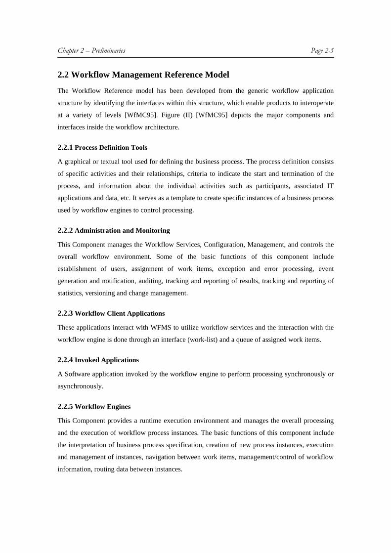
2.2.1 Process Definition Tools
A graphical or textual tool used for defining the business process. The process definition consists
of specific activities and their relationships, criteria to indicate the start and termination of the
process, and information about the individual activities such as participants, associated IT
applications and data, etc. It serves as a template to create specific instances of a business process
used by workflow engines to control processing.
2.2.2 Administration and Monitoring
This Component manages the Workflow Services, Configuration, Management, and controls the
overall workflow environment. Some of the basic functions of this component include
establishment of users, assignment of work items, exception and error processing, event
generation and notification, auditing, tracking and reporting of results, tracking and reporting of
statistics, versioning and change management.
2.2.3 Workflow Client Applications
These applications interact with WFMS to utilize workflow services and the interaction with the
workflow engine is done through an interface (work-list) and a queue of assigned work items.
2.2.4 Invoked Applications
A Software application invoked by the workflow engine to perform processing synchronously or
asynchronously.
2.2.5 Workflow Engines
This Component provides a runtime execution environment and manages the overall processing
and the execution of workflow process instances. The basic functions of this component include
the interpretation of business process specification, creation of new process instances, execution
and management of instances, navigation between work items, management/control of workflow
information, routing data between instances.

Chapter 2 – Preliminaries Page 2-6
FIGURE (II) WORKFLOW MANAGEMENT SYSTEM – REFERENCE MODEL
2.3 Process Definition Languages
The main purpose of a WfMS is the support of the definition, execution and control of the
processes. Since processes play a significant role in the functioning of WfMS, it is indispensable
to use an established framework for modeling and analyzing workflow processes [HL91, Kou95,
and Law97]. The following are some of the approaches used to model the workflow definitions.
2.3.1 Petri nets
The notion of classical Petri nets was invented by Carl Adam Petri in the sixties [Pet62]. The
classical petri net is a directed bipartite graph with two node types called places and transitions.
The nodes are connected via directed arcs. Connections between two nodes of the same kind are
not allowed. Petri nets have been used to model and analyze all kinds of processes with
applications ranging from protocols, hardware, and embedded systems to flexible manufacturing
systems, user interaction, and business processes [Aal00]. The last two decades have seen many
extensions to the classical petri nets, which facilitated the modeling of complex processes, where
data and time are important factors [Aal94, Jen96].
The graphical nature, formal semantics, expressiveness, tool-independent framework and
the availability of many analysis techniques of petri nets have established petri nets as a
workflow-modeling framework [Aal00]. However, the classical petri nets tend to be complex
while describing real processes. To address these problems, the classical petri net is extended
(high-level petri net) with color to model data, time and hierarchy to structure large models
[Jen96, Aal94, Hee94].

Chapter 2 – Preliminaries Page 2-7
Modeling a workflow process definition in terms of a petri net is rather straightforward: activities
(tasks) are modeled by transitions and conditions are modeled by places. A petri net which
models a workflow process definition (i.e. the life cycle of one case in isolation) is called a
WorkFlow net (WF-net). A WF-net satisfies two requirements. First, a WF-net has one input
place (i) and one output place (o). A token in i corresponds to a case, which needs to be handled,
a token in o corresponds to a case, which has been handled. Secondly, in a WF-net there are no
dangling tasks and/or conditions. Every task (transition) and condition (place) should contribute
to the processing of cases. Therefore, every transition t (place p) should be located on a path from
place i to place o. The latter requirement corresponds to strongly connectedness if o is connected
to i via an additional transition t*. A formal description of high-level petri nets and their
applications to workflow management is provided in [Aal00].
2.3.2 State and Activity charts
State charts have been used as a general-purpose specification formalism for dynamic systems
and are pursued in various research projects because of their excellent basis for providing formal
proofs. The method of state and activity charts is perceived by practitioners as more intuitive and
easier approach to learn than petri nets [DG97]. The model of state and activity charts was
proposed by Harel et al. [Ha87a] and was originally developed for reactive systems. Due to their
visualization, rigorous semantics, interoperability with other tools and methods and wide
acceptance in industry (UML), state charts are used as a workflow specification method.
The model comprises two dual views of specification [DG97]. Activities map directly to
the activities of a process definition. They describe the functional decomposition of a system and
represent the active components of a workflow specification. The dataflow between various
activities is specified in an activity chart in the form of a directed graph with data items
represented as arc annotations. The control flow between activities is specified in a state chart,
which reflects the behavior of a system. A state chart is a finite state machine with a distinguished
initial state and transitions driven by Event-Condition-Action rules (ECA rules). ECA rules are
often written as E[C]/A. Each transition arc between states is annotated with an ECA triple. A
transition from state X to state Y fires, if the specified event E occurs and the specified condition
C holds. The result is that state X is exited, state Y is entered and the specified action A is
executed. Conditions and actions are expressed in terms of data item variables. An action A can
explicitly start or stop an activity and can generate an event E or set a condition C. Each of the
three components may be empty. If all components are empty, then a transition can fire instantly,

Chapter 2 – Preliminaries Page 2-8
changing a state without any precondition. Every state change in a state chart induces a discrete
time dimension.
State charts have two important features namely, nested states and orthogonal
components. Nested states are states, which can themselves contain an entire state chart whereas
the orthogonal components denote the parallel execution of two state charts that are embedded in
the same higher-level state.
FIGURE (III): SIMPLE STATE CHART AND ITS STATE TREE REPRESENTATION
The left portion of the figure (III) [DG97] shows a simple state chart and the right portion
shows its corresponding state tree representation. The state chart consists of states from A
through I, where the initial states are marked by red arcs without source. The orthogonal
components are separated by a dashed-line with their corresponding higher-level state. In the
above figure, States C and F are orthogonal states inside a nested state B whereas the states B, D,
G and H are initial states. A more detailed formal description about state and activity charts can
be found in [DG97].
2.3.3 XPDL (XML Process Definition Language)
XPDL uses XML to describe a business process. XPDL provides organizations with a common
framework for implementing business process management and workflow engines, and for
designing, analyzing, and exchanging business processes. XPDL is based on the recognized
workflow standard, WfMC reference model [WfMC95].
XPDL is conceived of as a graph-structured language with additional concepts to handle
blocks. Scoping issues are relevant at the package and process levels. Process definitions cannot
be nested. Routing is handled by specification of transitions between activities. The activities in a
process can be thought of as the nodes of a directed graph, with the transitions being the edges.
Conditions associated with the transitions determine the execution of appropriate activity or
activities at runtime. The left portion of the figure (IV) shows the definitions of various activities
and transitions involved in the workflow process whereas the right portion of the figure depicts its
F
H
I
B
D E
G
A
C

Chapter 2 – Preliminaries Page 2-9
corresponding graph-structure. All activities from starting from A (Start Activity) through D (End
Activity) are represented as nodes and the transitions are represented as the edges between them.
Conditions and condition types (XOR, AND) associated with the transitions decide the execution
of activity. In the figure (IV), a transition from activity A to activity C will occur if the condition
(GOTO_C) is satisfied. Activities E and F are the orthogonal components, as specified by the
AND split type at B. A detailed description on specification of XPDL is provided in [WfMC02].
One of the key elements of the XPDL is its extensibility to handle information used by a variety
of different tools. Based upon a limited number of entities that describe a workflow process
definition ('Minimum Meta Model'), XPDL thus supports a number of differing approaches
[WfMC02]. XPDL is extendable, allowing the addition of elements and attributes as well as the
import of data types and operations that are defined in other specifications. Moreover, XPDL
provides a natural fit with graphical representations of business processes.
FIGURE (IV): A XPDL REPRESENTATION AND ITS CORRESPONDING GRAPH-
STRUCTURE OF A SIMPLE WORKFLOW PROCESS
2.3.4 BPEL4WS (Business Process Execution Language for Web Services)
BPEL4WS is an XML based flow languages that provides a formal specification of business
process behavior based exclusively on web services. It defines a model and grammar for
describing the behavior of a business process based on interactions between the process and its
partners. IBM, Microsoft, BEA Systems, SAP and Siebel Systems originally authored the
BPEL4WS specification. BPEL4WS is a block-structured programming language, allowing
recursive blocks, but restricting definitions and declarations to be top-level.

Chapter 2 – Preliminaries Page 2-10
A BPEL4WS process definition is made up of four basic components: activities (subtasks
of process), control links (define the process control flow), a series of partner-links (placeholders
for service providers and process callers), variables (hold data). The optional components include
the correlations sets, which provide support for process instance identification, the fault handlers
that enclose activities performed in case of errors and the compensation handlers that enable
compensatory activities in the event of actions that cannot be explicitly undone. The control flow
is defined by all the possible activities as defined by BPEL semantics. The control flow is a nice
hybrid model half-way between block structured and state transition control flow definitions. The
model uses links to establish the dependencies between block definitions. The links are defined
inside the flow and are used to connect a source activity to a target activity. Sequential and
concurrent control between activities is provided by sequence and flow control constructs. Three
types of activities handle the message flow: receive, reply and invoke. Receive and reply may be
assigned to the same operation in case of request/response. Invoke is used to define a solicit
response operation type. The information is passed between the different activities in an implicit
way through the sharing of globally visible data containers. Containers may exchange specific
data elements via the use of Assign statements. BPEL4WS allows long-running transactions to
run as web services with better consistency and reliability. Like XPDL and state charts, BPEL
provides rich visualization, interoperability with other tools and methods, rigorous semantics and
wide acceptance in industry.
2.4 Overview of Workflow Management Systems
Workflow Management Systems are designed to enable the enactment of business processes, i.e. to
extract and maintain the process logic between business applications. Within the WfMS,
heterogeneous applications are connected through a given process definition. WFMS orchestrate the
control and the data flow between a workflow's activities, based on a high-level specification of the
intended behavior.
2.4.1 Characteristics of a WfMS
From a broader view, WfMSs may be characterized as providing support in three functional
areas as depicted in the figure (V) [Dav95].
2.4.1.1 Build-time functions
The Build-time functions are those, which result in a computerized definition of a business
process. During this phase, a business process is translated from the real world into process

Chapter 2 – Preliminaries Page 2-11
definition using a process definition language. The process definition enables the interchange of
workflow relevant data between the build-time tools and runtime products. Some workflow
systems may allow dynamic alterations to process definitions from the run-time operational
environment, as indicated by the feedback arrow in the diagram.
2.4.1.2 Run-time control functions
In this phase, the process definition is interpreted by workflow engine, which is responsible for
creating and controlling operational instances of the process, scheduling the various activities
steps within the process and invoking the appropriate human and IT application resources, etc.
These run-time process control functions act as an interface between the process as modeled
within the process definition and the process as it is seen in the real world, reflected in the
runtime interactions of users and IT application tools.
2.4.1.3 Run-time interactions
During this phase, individual activities within a workflow process interact with human operations
(interactive activities), often implemented in conjunction with the use of a particular IT tool, or
with information processing operations requiring a particular application program (automatic
activities) to operate on some defined information. Further, Individual activities inside a
workflow process interact with the process control software to transfer control between them, to
ascertain the operational status of processes, to invoke application tools and pass the appropriate
data, etc.
FIGURE (V): CHARACTERISTICS OF WORKFLOW MANAGEMENT SYSTEMS
Chapter 2 – Preliminaries Page 2-12
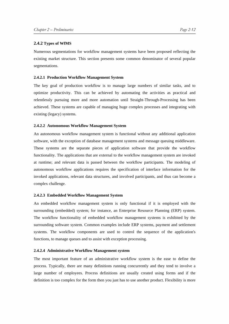
2.4.2 Types of WfMS
Numerous segmentations for workflow management systems have been proposed reflecting the
existing market structure. This section presents some common denominator of several popular
segmentations.
2.4.2.1 Production Workflow Management System
The key goal of production workflow is to manage large numbers of similar tasks, and to
optimize productivity. This can be achieved by automating the activities as practical and
relentlessly pursuing more and more automation until Straight-Through-Processing has been
achieved. These systems are capable of managing huge complex processes and integrating with
existing (legacy) systems.
2.4.2.2 Autonomous Workflow Management System
An autonomous workflow management system is functional without any additional application
software, with the exception of database management systems and message queuing middleware.
These systems are the separate pieces of application software that provide the workflow
functionality. The applications that are external to the workflow management system are invoked
at runtime; and relevant data is passed between the workflow participants. The modeling of
autonomous workflow applications requires the specification of interface information for the
invoked applications, relevant data structures, and involved participants, and thus can become a
complex challenge.
2.4.2.3 Embedded Workflow Management System
An embedded workflow management system is only functional if it is employed with the
surrounding (embedded) system; for instance, an Enterprise Resource Planning (ERP) system.
The workflow functionality of embedded workflow management systems is exhibited by the
surrounding software system. Common examples include ERP systems, payment and settlement
systems. The workflow components are used to control the sequence of the application's
functions, to manage queues and to assist with exception processing.
2.4.2.4 Administrative Workflow Management system
The most important feature of an administrative workflow system is the ease to define the
process. Typically, there are many definitions running concurrently and they tend to involve a
large number of employees. Process definitions are usually created using forms and if the
definition is too complex for the form then you just has to use another product. Flexibility is more

Chapter 2 – Preliminaries Page 2-13
important than productivity, and these systems handle one or two orders of magnitude lower
numbers of instances per hour than production WfMS.
2.4.2.5 Collaborative Workflow management system
Collaborative workflow system focuses on teams working together towards common goals.
Groups can vary from small, project-oriented teams, to widely dispersed people with interests in
common. Effective use of collaborative workflow to support team working is now considered a
vital element in the success of enterprises of all kinds.
2.4.2.6 Ad-Hoc Workflow Management system
Ad-Hoc workflow systems allow to create and amend process definitions very quickly and easily
to meet circumstances as they arise. Therefore, it is possible to have almost as many process
definitions as there are instances of the definitions. Ad-Hoc workflow maximizes flexibility in
areas where throughput and security are not major concerns. Its users own their own processes.
2.4.2.7 Dependable Workflow Technology
Workflow technology aims to support business processes that may span different, largely
autonomous, organizational units within large enterprises or even multiple enterprises. Examples
of such workflows would be the processing of company credit requests in an internationally
operating bank or nation-wide health-care management. Workflow technology is also an
important asset for Internet-based business-to-business (e.g., supply chains) and business-to-
consumer (e.g., auctions) e-services.
2.4.3 State-of-the-art WfMS
2.4.3.1 MQSeries workflow (IBM)
MQSeries workflow offers a true object-oriented design together with a high level of re-usability.
MQSeries workflow concentrates on procedure management and powerful organization modeling
while leaving activity implementation to the programmer. Activities are complex and must be
programmed to fit requirements. It uses process model, a graph-based workflow language for
specifying the workflows. By using an MQSeries runtime client, users can start the execution of
the modeled processes, monitor and manipulate the running process instances, change the work
list view by filtering or sorting the work items and transfer work items to work lists of other users
(change work assignments). However, dynamic adaptations of running workflow instances are
not addressed in MQSeries workflow. Workflow engine can directly co-operate with applications

Chapter 2 – Preliminaries Page 2-14
and other workflow engines through XML encoded MQSeries messages. MQSeries Workflow
provides a process automation system for managing people, data, applications, and business
processes throughout an organization, including external partners via the Internet or intranets and
extranets. With this approach to workflow, IBM provides a robust infrastructure of messaging
(MQSeries Messaging) and application integration (MQSeries Integrator) upon which
production-level workflow applications are built. MQSeries Workflow helps both business and IT
users effectively leverage their existing infrastructure for process automation and management.
2.4.3.2 Bizflow 2000 (Handysoft)
Bizflow is a flexible workflow engine that provides well designed graphical definition tool
associated to a form definition tool BizForm. It has a comprehensive Web based interface as well
as a client/server interface based on ActiveX objects. The activity interface is generated from the
information given at process definition level, together with applications in the form of documents
that can contain scripts to access process context. It has a fair organization model and set of
dispatching rule. It is capable of handling dynamic adaptations of running workflow instances. It
provides flexible process definition, low cost application definition through forms and interpreted
interface and deployment of large administrative and light production applications over the
internet.
2.4.3.3 ADEPT
The ADEPT project at the University of Ulm aims at providing flexible workflow support for
advanced applications, mainly in the context of hospital environments [RD97, RD98]. The
ADEPT build time components enable the definition and management of WF templates (ADEPT
workflow editor), the description of inter-WF dependencies (ADEPT interaction editor), the
modeling of organizational entities (ADEPT Organization modeler), the specification of security
constraints, and the plug-in of application components (ADEPT application configuration tool).
All relevant information is stored in the ADEPT repository. The ADEPT WfMS is based on a
multi-server architecture[RRD03]. A WF instance may either be controlled by a single server or
by multiple servers if favorable. To each server different clients can be connected. ADEPT
comprises standard runtime clients for end users as well as for system and process administrators.
These clients enable work list display and manipulation (ADEPT work list handler), WF
monitoring (ADEPT monitoring client), activity program execution, dynamic WF changes, and
system configuration. Dynamic modifications of workflows are modeled using ADEPTflex..
ADEPT offers sophisticated modeling concepts and advanced features, like temporal constraint

Chapter 2 – Preliminaries Page 2-15
management, ad-hocWF changes, WF schema evolution, synchronization of inter-workflow
dependencies, and scalability [RRD03].
2.5 Overview of Content Management Systems
2.5.1 Definition
“A Content Management System (CMS) is a piece of software that manages or controls
the development of a web site in an organization”. “A Content Management System is a tool that
enables a web developer in an organization to manage and update the web content with much
ease”.
A Content Management System empowers an organization to create and publish its web
content in a more structured, effective and convenient manner. A CMS helps an organization in
achieving a distributed content management and control by bestowing a web developer with the
ability to administer the content without the aid of a webmaster. It can also help an organization
in streamlining and automating its content administration by hiding the complexities of HTML
from the developer.
2.5.2 Principal Components of CMS
A Content Management System consists of four principal components as illustrated in figure (VI)
[RS03].
FIGURE (VI): PRINCIPAL ELEMENTS OF A CONTENT MANAGEMENT SYSTEM
2.5.2.1 Front-end CMS
The Front-end of the CMS represents the online/published version of the website, which can be
perceived by the visitors of the website. It contains all the webpages, documents, forms, images,
Front-end Back-end
Templates
Database
Web Site Visitors Content
Managers

Chapter 2 – Preliminaries Page 2-16
multimedia and other prevalent forms of web content. The front-end acts as a visitor interface to
authorize themselves and upload their content (documents) into the server.
2.5.2.2 Back-end CMS
The Back-end component provides the strength to the entire CMS from an organization
perspective. The back-end of a CMS is an easy-to-use interface which allows non-technical
people (such as subject specialist, staff) to edit or enter content. The back-end can be reached
through a website, which is equipped with access control for different levels of authority. The
web developers are provided with their appropriate access control level so that they will able to
post or remove content from a predetermined section of the website. The web masters are
equipped with the access to control/manage the entire website, the ability to change the templates
(ie., creation of new web pages with a different design and layout), to include novel features, to
change the structure of the site, and to manage the user access to the back-end.
2.5.2.3 Templates
Templates are the structures that format and display content following a request from a user for a
particular web page. Templates ensure a consistent, professional look and feel for all the content
on the site. The templates represent the skeleton of a web page where the content of the web page
is embedded into it. These templates are developed by a web master using the web page format
designed by professional web developer. A master template is chosen for every web page by the
web master, which is used by the web developers in the organization to post their content.
2.5.2.4 Database
The Database is the key to Content Management Systems. The database acts as a central
repository for retrieving the content, templates, graphics, users and metadata. A true CMS does
not store flat, static HTML pages. Instead, the System places the content in a relational database
capable of storing a variety of binary and text. The database is also capable of storing metadata
including the author info, creation, publishing and expiring dates, content descriptions and
indexing information, revision history and a range of other content-related data.
2.5.3 Functions of CMS
The basic functions of CMS can be classified into three categories: Creation, Management, and
Publication. An advanced CMS can have many functions (archives, built-in search engines,
permission control, workflow management etc) in addition to the ones stated above. The CMS
functional scope and the content life cycle are depicted in the figure (I).

Chapter 2 – Preliminaries Page 2-17
2.5.3.1 Creation
The Creation Phase involves processing two sub stages: Authoring and developing, before it is
forwarded to the management phase. In this Phase, the initial content is provided as an input into
the CMS. A Manager is responsible for assigning all the particulars of the task. A professional
web designer designs a web page format, which involves specifying the logo, standard navigation
options etc. This common web page format is then used to create a master template. All the web
developers (Authors) use this master template in generating the content in an environment that is
most appropriate for this task. This authored and developed content is sent to the so-called
management phase for perusal. This authored content is stored in a repository (XML Files or
records in database). The Repository enables the System to exercise version control over the
entire content.
2.5.3.2 Management
This Phase consists of editing, assembling, translating, and finally reviewing the content before it
is published for viewing by various website visitors. In this phase, the content is sent into an
approval, rejection or revisal workflow. An Editor can approve, reject, or revise the content after
checking the semantics of the content. If the content needs revision, either he can send it back to
the appropriate author for revision or he can edit the content by himself. The content is forwarded
to approval stage if it has been accepted by the editor. The approver then forwards the content
either to translator or to the publication stage.
2.5.3.3 Publication
This final stage begins upon the approval of material in the management stage. The approved
content is embedded into the master template thereby eliminating the time need to format the
content to fit the design of the page. The content is then sent to staging upon the final approval by
the Quality Assurance. In this stage, the content is seen as if it were delivered in its chosen forms.
The content is then published onto web server for viewing by various website visitors.
2.5.4 Benefits of CMS
There is a wide range of business benefits that can be obtained by implementing a CMS. The
following are some of the business benefits of Content Management Systems.
2.5.4.1 Content accuracy
Using only standard office applications, business owners can create and update content by simply
dragging and dropping files to submit content to the Content Management System, which

Chapter 2 – Preliminaries Page 2-18
automatically applies corporate style and formatting to publish the new content and maintain a
consistent look and feel to the site. By achieving content changes in much reduced times and by
ensuring content accuracy, a CMS reduces the time to market, delivers improvements to the user
experience and saves costs through rationalized resource utilization.
2.5.4.2 Consistent corporate branding
A CMS establishes the design philosophy and ensures it is consistently applied throughout the
site to maintain corporate identity and branding. The use of templates allows a ‘design once’
approach, which, by separating content from presentation, reduces the time and effort, required to
create and police the brand. The benefit is extended to re-branding activities that, being far easier
and less costly to implement, allow the adoption of a more dynamic and vibrant corporate
identity.
2.5.4.3 Streamlined centralized management
A CMS that uses template based publishing and a dynamic content repository centralizes control
to deliver numerous benefits and efficiencies. Development and deployment investments made
for one site can be leveraged for the deployment of further sites that require the same corporate
values. Such centralized management delivers on-going efficiencies and cost savings by allowing
further changes to be synchronized across multiple sites as a single activity thereby avoiding
redundancy.
2.5.4.4 Guarding Content Value
Protecting the value of the content is the pivotal issue to a company’s ability to succeed. It must
be accurate, up-to-date and easy to find. Inaccurate content, out-of-date and poorly structured
content symbolizes commercial lethargy, hard to navigate and poses a threat to company
credibility. A CMS guards the value of content by accelerating and automating publication
processes, putting control of content into the hands of the business experts and providing
centralized administration of its presentation.
2.5.5 State-of-the-art CMS
DeepWeb CMS
DeepWeb CMS is one of the powerful Content Management Systems available in the market
today. DeepWeb CMS provides an easy-to-use, user-friendly, platform independent and highly
extensible CMS framework to its users. In DeepWeb CMS, using a standard web browser,

Chapter 2 – Preliminaries Page 2-19
business experts can create and update content by either entering text or simply dragging and
dropping files to submit content to the Deepweb CMS, which automatically applies corporate
style and formatting to publish the new content and maintain a consistent look and feel to the site.
By achieving content changes in much reduced times and by ensuring content accuracy, Deepweb
CMS reduces the time to market, delivers improvements to the user experience and saves costs
through rationalized resource utilization. The use of templates allows a ‘design once’ approach,
which, by separating content from presentation, reduces the time and effort, required to create and
police the brand. Deepweb CMS guards the value of content by accelerating and automating
publication processes, putting control of content into the hands of the business experts and
providing centralized administration of its presentation. More detailed information regarding the
system architecture and features of DeepWeb CMS can be found at [Var04].
2.6 Service Oriented Architectures
[Nik04] predicts that by 2008, Service–Oriented Architectures (SOAs) will likely be a prevailing
software engineering practice, ending the 40-year domination of monolithic software architecture.
They model the enterprise as the collection of services that are available across the enterprise.
SOA lets the heterogeneous environments and applications exist while leveraging existing
applications and infrastructure [Pal01].
SOA is a relatively new term, but the term "service" as it relates to a software service has
been around since at least the early 1990s, when it was used in Tuxedo to describe "services" and
"service processes" [Her02]. Sun defined SOA more rigorously in the late 1990s to describe Jini
[Kei99], a lightweight environment for dynamically discovering and using services on a network.
The technology is used mostly in reference to allowing "network plug and play" for devices. It
allows devices such as printers to dynamically connect to and download drivers from the network
and register their services as being available. SOA is an alternative model to the more
traditionally tightly-coupled object-oriented models like Common Object Request Broker
Architecture (CORBA) and Distributed Component Object Model (DCOM). SOA is described to
be a set of components which can be invoked, and whose interface descriptions can be published
and discovered (W3C). More precisely, one could define the Service-Oriented Architecture
(SOA) as” The aggregation of components satisfying a business driver” [Pal01].
SOA is an architectural style whose goal is to achieve loose coupling among interacting
software agents. A service is a unit of work done by a service provider to achieve desired end
results for a service consumer. Both provider and consumer are roles played by software agents
on behalf of their owners. SOA is a system for linking resources on demand. In SOA, resources

Chapter 2 – Preliminaries Page 2-20
are made available to other participants in the network as independent services that are accessed
in a standardized way. This provides for more flexible loose coupling of resources than in
traditional systems architectures
The most important aspect of SOA is that it separates the service's implementation from
its interface. In other words, it separates the "what" from the "how." Service consumers view a
service simply as an endpoint that supports a particular request format or contract. Service
consumers are not concerned with how the service goes about executing their requests; they
expect only that it will. Consumers also expect that their interaction with the service will follow a
contract, an agreed-upon interaction between two parties. The way the service executes tasks
given to it by service consumers is irrelevant. The only requirement is that the service sends the
response back to the consumer in the agreed-upon format.
2.6.1 Characteristics & Benefits of SOA
The software components in a SOA are services based on standard protocols and the services in
SOA have minimum amount of interdependencies. Communication infrastructure used within an
SOA should be designed to be independent of the underlying protocol layer. SOA uses service
granularity to provide effective composition, encapsulation and management of services.
SOA provides location independence i.e. services need not be associated with a particular
system on a particular network. SOA uses protocol-independent communication framework
which renders code reusability. It offers better adaptability and faster response rate to changing
business requirements. It allows easier application development, run-time deployment and better
service management SOA is the loosely coupled system architecture, which allows easy
integration by composition of applications, processes, or more complex services from other less
complex services. It provides authentication and authorization of Service consumers, and all
security functionality via Services interfaces rather than tightly-coupled mechanisms. It allows
service consumers (ex. Web Services) to find and connect to available Services dynamically.
Applications can be exposed more easily to diverse clients: Windows clients, ASP.NET/JSP, etc.
2.6.2 Web Services
Web Services are an open standards-based way of creating and offering SOAs. Web Services are
able to exchange structured documents that contain different amounts of information, as well as
information about that information, known as metadata. In other words, Web Services can be
coarse-grained (Scope of functionality that a service exposes which is considered to be
intelligently structured to meet the business needs). Such coarse granularity is one of the most

Chapter 2 – Preliminaries Page 2-21
Service Registry
Service Provider
Service Requestor
important features of SOAs. Web Services are derived from SOAs with additional constraints
like, Interfaces must be based on protocols like HTTP, SMTP, FTP and the messages must be in
XML, except for binary data. Web Services use SOA because they are similar in their approach
regarding inoperable components, a network addressable interface, component re-use and client
neutrality.
2.6.2.1 Generic architecture of Web Services
A complete Web services architecture consists of three roles (runtime environments)
A) Service Provider
The service provider is the system that runs the Web service and provides access to the service
through a standard interface. This role is composed of two entities:
1. Service interface provider: This entity provides interfaces into the applications used
as Web services; for example, a standard organization.
2. Service implementation provider: This entity provides the implementation of the
applications used as Web services. For example, an application server or any engine that
hosts a service.
B) Service Requester
This role, also known as the service consumer or client, contains applications that use Web
services. The service requester binds to the service offered by a service provider and invokes the
service.
C) Service Registry
The service registry acts as a service broker for Web services. In other words, the service registry
provides a means for service requesters to find Web services offered by service providers.
FIGURE (VII): GENERIC ARCHITECTURE OF SOA

Chapter 2 – Preliminaries Page 2-22
A service provider can publish the services it offers to the service registry. Service requesters
query the service registry to find information about available services such as where to locate
these services, and how to bind to them. This process can be visualized from the figure [Has03].
An important feature of Web services is that they are defined in terms of the messages that flow
on the network between the systems that play the three roles. The messages are defined in terms
of a common, standard language (XML), and use standardized protocols such as HTTP running
over TCP/IP. This commonality means that Web services can work in an environment where the
systems that are playing the different roles can be of different types. Furthermore, a role does not
have to be aware of how the other roles are implemented.
2.6.2.2 Technologies of Web Services
A) Simple Object Access Protocol (SOAP)
SOAP is the Web services messaging protocol. It is the core technology that allows Web services
to interoperate because of its operating-system and programming-language independence. It is a
standard XML messaging light weight protocol used to exchange information between two
applications. It has three parts
1. An envelope that defines a framework for describing what is in a message and how to
process it.
2. A set of encoding rules for expressing instances of application defined data types.
This contains the information about security, caching, routing, and management etc.
3. A convention for representing remote procedure calls and responses.
B) Web Services Description Language (WSDL)
WSDL is the XML language for describing Web services. It is used to create descriptions of Web
service interfaces and their implementations so that they can be found and integrated
automatically. WSDL provides a grammar for describing services as a set of endpoints that
exchange messages. A WSDL document serves as a language and platform-agnostic (XML)
description of one or more services. It describes the services, how to access them, and what type
of response to expect. A WSDL document can be either privately exchanged or posted to a UDDI
registry (either public or private) to allow broader access. In truth, you could expose a pure Java
interface, text-based documentation, or any other interface for the service if you choose to do that.
WSDL offers a neutral, standardized interface format. WSDL is an XML-based file format for
describing types, messages, operations, interfaces (called PortTypes), locations, and protocol
bindings. You use WSDL to describe Web services as a set of endpoints operating on messages.

Chapter 2 – Preliminaries Page 2-23
WSDL can describe either document-oriented or procedure-oriented information. In WSDL,
messages describe the communication between client and service, described by the data types
exchanged. The operations consist of incoming and outgoing messages. PortTypes consist of a
collection of operations. The port types are then bound to certain protocols (this is called a
binding). WSDL supports bindings to SOAP 1.1, HTTP GET/POST, and MIME protocols.
However, WSDL is extensible and can be used with other types of network protocols and
message formats.
C) Universal Description Discovery and Integration (UDDI)
UDDI is the Web services database technology. It provides a standardized method for publishing
and discovering Web services. The following entities comprise the core of the UDDI data model
1. Business entity: Business entities are the white and yellow pages of the registry. They
represent basic business information about a service provider such as business name, contact
information, description, identifiers, and categorization.
2. Business service: A Business service classifies an individual, logical service. The green
pages, part 1, are used to describe, in general, nontechnical terms, a set of services provided
by the business.
3. Binding template: A binding template, sometimes called access locator, contains technical
service access information. The green pages, part 2, contain pointers to technical descriptions
and the access point URL. A binding template points to a service implementation description
(typically WSDL).
4. tModel: A tModel, also called service type, is an abstract description of a particular
specification or behavior to which the Web service adheres. It is a digital identification,
holding metadata about type specifications as well as categorization information. A tModel
points to a service interface description, typically WSDL (for example, through a URL).
2.6.2.3 Applicability of Web Services
Web services build on the concept of distributed computing. The categories of the Web Services:
A) Business information
Businesses can share information with consumers or other businesses. Examples are stock quotes,
news, and weather forecasts.

Chapter 2 – Preliminaries Page 2-24
B) Business process externalization
Businesses can provide transactional, fee-based services for customers. Examples are reservation
systems, auction sites, and credit checking.
C) Business integration
Web services can be used to dynamically integrate a company's processes with those of other
companies or institutions. For example, a Web service could provide a set of high-level travel
features by coordinating lower-level Web services for air travel, hotels, and car rental.
2.6.2.4 Evaluation of Web Services with Various SOA Technologies
Some of the major advantages of Web Services against CORBA, DCOM, and RMI are illustrated
below.
A) Interoperability
There is a tight coupling between client and the server in CORBA, RMI since the both ends must
share the same interface whereas in Web Services, Everything is loosely coupled since it uses the
universally accepted language as the medium of transferring the messages between client and the
server.
B) Serializability
This factor influences various issues such as persistence, extensibility and ease of interoperation
with other frameworks. Web Services allows for user-defined serialization mechanisms. Web
Services being XML based, is too verbose as compared to CORBA.
C) Ease of Deployment and Assembly
Deploying any service and discovering the same is very cumbersome in CORBA, RMI where as
in Web Services there are some technologies used like UDDI, WSDL, SOAP which makes easy
service deployment and discovery.
D) Secure architectures with firewalls
Web Services uses HTTP to transfer or exchange information between two systems and most
firewalls have been configured to accept HTTP traffic hence messages can tunnel through
firewalls. CORBA does not use a specific port for communication.

Chapter 2 – Preliminaries Page 2-25
E) Degree of familiarity
This relates to the degree of familiarity with the technology, learning curve, and number of
developers required/available. In this context, Web services have an upper hand, since they are
based on well-known and heavily used protocols/formats, namely HTTP and XML.

CHAPTER 3 DESIGN
3.1 Overview of Existing System (Mentor-Lite)
The Mentor-lite prototype has evolved from the Mentor WfMS ("Middleware for Enterprise-
Wide Workflow Management") [MWG+98, MWW+98]. Mentor WfMS is a joint project of the
University of the Saarland, the Union Bank of Switzerland, and ETH Zurich [WGR+00,
WWW+00, WWW+96]. The focus of the project is on an enterprise-wide workflow management.
Workflows in this category may span multiple organizational units each unit having its own
workflow server, involve a variety of heterogeneous information systems, and require many
thousands of clients to interact with the WfMS. The project aims to develop a scalable and highly
available environment for the execution and monitoring of workflows, seamlessly integrated with
a specification and verification environment [WWW+97]. Though Mentor WfMS was able to
achieve a highly distributed, scalable, and available environment for the execution and
monitoring of workflows, it was not able to achieve interoperability between heterogeneous
environments. This limitation prompted the development of Mentor-lite, which aims to develop a
simpler architecture compared to its predecessor (Mentor). The Mentor-lite prototype has been
developed within the research project "Architecture, Configuration, and Administration of Large
Workflow Management Systems" [MWG+98, MWW+98]. Mentor-lite is a Light-weight
Workflow Management System in which the work list management and history management are
flexible. Mentor-lite is a scalable, distributed WfMS that reconciles a rigorous specification
method with distributed middleware architecture as a step towards highly dependable workflow
management. It also aims to recommend an appropriate system configuration in terms of
replicated workflow, application, and communication servers, so as to meet given goals for
performance, and availability at low system costs. The main goal of Mentor-lite has been to build
a light-weight, extensible and tailorable workflow management system (WFMS) with small
footprint and easy-to-use administration capabilities [WGR+00].
3.1.1 Components of Mentor-Lite
3.1.1.1 Workflow Engine
The Mentor-lite workflow engine provides a runtime execution environment and manages the
overall processing and the execution of workflow process instances. The Mentor-Lite workflow
engine comprises of three basic components.

Chapter 3 – Design Page 3-27
A) Workflow Interpreter
Workflow Interpreter is the basic building block of Mentor-lite for workflow specifications
[WGR+00]. The workflow interpreter interprets at runtime, the workflow specifications, which
are modeled at design time using state and activity chart process definition language. The
workflow interpreter performs a stepwise execution of the workflow specification at the runtime
according to its formal semantics [DG97]. The interpreter checks the values of conditions and
performs the steps in the workflow following the specification by setting conditions or starting
activities.
B) Communication Manager
The Communication Manager is responsible for sending and receiving synchronization messages
between the engines and invoking the workflow interpreter [WGR+00]. These messages contain
information about locally raised events, updates of state chart variables and state information of
the local engine. When a synchronization message is received, the corresponding updates at the
receiving site are performed.
C) Log Manager
The log manager provides logging facilities and recovery mechanisms [WGR+00]. It records all
the detailed information about the changes to state, event, and data-element information of all
active workflow partitions that the engine server is responsible in a DBMS. It can be used to
detect a crashed state in the event of system crash. The stored logging information (conditions)
enables log manager to recover from a crashed state by resuming the execution from crashed state
without processing its previous states.
3.1.1.2 XML-Mediator
The XML Mediator provides a high-level abstraction for WfMS interoperability in the context of
global workflow management. It offers an Internet-based, worldwide accessible interface to
invoke workflows or activities and pass results to the proper destinations [WGR+00]. The
mediator as a “middle man” bundles the traffic between the workflow and business-object servers
on one side and applications on the other side. It is responsible for interpretation and redirection
of workflow client’s control flow data the corresponding workflow server and business data to the
corresponding repository.

Chapter 3 – Design Page 3-28
3.1.1.3 Workflow Specification Environment
The workflows are specified in terms of state and activity charts specification formalism [as
discussed in Section 2.3.2]. Mentor-Lite uses a commercially available run-time system for state
and activity charts as the workflow engine, which serves as a common denominator of different
modeling languages that can be mapped onto such an engine. Thus, workflow applications can be
specified in whatever modeling language is considered most appropriate, and this specification
will be transformed into a "canonical" representation that is suitable for our engine.
3.1.1.4 Worklist Manager
Each activity that becomes ready for execution during a workflow execution constitutes a work
item that is communicated to a worklist manager. The worklist manager assigns a work item
dynamically to one of the actors based on their expertise, experience, availability and workload.
The worklist manager retrieves these role resolution parameters from worklist database.
Furthermore, the worklist manager also uses additional time-related information (deadlines) about
previously processed work items that is extracted from the history database. Organizational
structure of the enterprise and workflow-instance-specific restrictions are the additional
parameters, which can influence the dynamic role resolution of roles into actors.
3.1.1.5 History Manager
The task of history management is to implement efficiently a powerful temporal database. The
temporal database should be able to answer queries on the history of workflows as well as on
their projected future. Inserts into this database are performed during workflow execution.
Temporal queries are used to retrieve information from this database, both off-line for
administration purposes and on-line during workflow execution for control flow decisions. The
workflow history can serve several purposes. It can be used for simple monitoring of a single
workflow, or for complex decisions on improving business processes based on histories of several
workflows together. The history can also be used for time-dependent decisions in a workflow
such as sending a reminder when a bill has not been paid in time.
3.1.1.6 Repositories
Mentor-lite uses three repositories for storage and retrieval of information. Each of these
repositories is associated with a component of the Mentor-lite workflow engine. Worklist and
Workflow repositories can be shared by Mentor-lite workflow engines at different sites.
A) Worklist Repository

Chapter 3 – Design Page 3-29
Mentor-lite uses this repository to store all the roles specified in workflow specification, all the
actors who are responsible and capable of performing the tasks of specified roles, and all the
detailed information about interactive activities (i.e., priority, start time, dead line, status,
description of the activity) that are assigned to corresponding actors. Worklist manager issues
queries to retrieve the information about Worklist actors dynamically from this repository and
assigns work items to the actors based on the workload, experience, presence.
B) Workflow Repository
This repository stores information about the workflow specifications in the form state, activity,
and module charts. Workflow interpreter uses this repository to interpret the workflow
specifications at runtime.
C) Workflow Log
Mentor-lite provides logging information and recovery details based on the information stored in
this repository. This repository stores detailed information about all the running workflow
instances (i.e., states, activities, events, conditions, user data, and timeouts for every workflow
instance). The log manager can use this repository to retrieve information about all the activities
that are already performed, current state, start and end time of workflow instances, condition
values etc.
3.1.2 Features of Mentor-Lite
3.1.2.1 Light-Weight and Flexible WfMS
Retaining a light-weight nature in WfMSs is an important feature in achieving a flexible WfMS.
Mentor-lite achieves the light-weight nature by modeling the system components like history
management and worklist management as extensions on top of the workflow kernel [as depicted
in figure VIII] and thereby implementing these extensions as workflows themselves. This
approach provides a flexible and open-modular architecture, where components can be added or
replaced by alternative implementations.
3.1.2.2 History Management
A History manager is an essential WfMS component that helps in analyzing active and already
completed workflow instances. Mentor-lite’s history manager provides an efficient

Chapter 3 – Design Page 3-30
implementation of a powerful temporal database, which provides detailed information about the
control flow decisions during workflow execution and offline administrative support.
3.1.2.3 Platform Independence
By using the Java and Internet technology (XML, DHTML), Mentor-lite provides a high degree
of platform independence, since it is feasible to access the system from a variety of hardware and
software platforms. Mentor-lite is successfully implemented in both linux and windows
platforms.
3.1.2.4 Flexible exception handling and dynamic modifications
The Interpretation of workflow specifications at runtime by the Mentor-lite’s workflow
interpreter enables Mentor-lite to achieve flexible exception handling and dynamic modifications
during runtime.
3.1.2.5 Conformance with WfMC Standards
The Mentor-lite prototype has been built based on the reference architecture of WfMC1. This
feature serves as a basis for evaluating Mentor-lite’s architecture with various architectures of
real systems
3.1.3 System Architecture of Mentor-Lite
The Mentor-lite architecture as depicted in the figure (VIII) [WGR+00] makes use of XML/XSL
support on the client side, an http server with efficient support for Servlets at the mediator level,
and standard SQL (via JDBC) and the most basic object-oriented middleware services of CORBA
to interoperate with the various business-object and workflow servers. The Mentor-lite workflow
engine, an interpreter for a specifically designed statechart dialect [DG97] runs as a CORBA
application server, coined DSIserver (Distributed Statechart Interpreter), or as a collection of
such servers on different computers with support for decentralized execution of sub-workflows
[WGR+00]. The workflow engine has been written in C and wrapped by C++ objects, while the
application wrappers are written in Java. Mentor-lite uses Iona’s Orbix product, which acts as a
CORBA-compliant request broker. It’s IDL interface provides a method to start a workflow
instance and a method to set variables and conditions within the workflow instance. The core of
the XML mediator is implemented using Oracle’s XSQL servlet, which serves to combine the
results of SQL queries into XML documents or to extract SQL updates from such documents. The
1 Refer to section 2.2

Chapter 3 – Design Page 3-31
mediator acts a “middle man” between the clients and the workflow engines as well as the
repositories. Mentor-lite uses Oracle 8i database server to store and retrieve information from its
repositories (tables). The Mentor-lite architecture can be viewed as composition of three main
components: Workflow Server (DSIserver), XML mediator, and repositories.
The working of Mentor-lite is illustrated as follows: the Communication manager (CM)
of the workflow engine receives the workflow instance, which is started using the Orbix’s IDL
interface and inserts it into a workflow Queue. The communication manager then invokes the
workflow interpreter as well as the log manager with the first workflow instance in the workflow

Chapter 3 – Design Page 3-32
FIGURE (VIII): SYSTEM ARCHITECTURE OF MENTOR-LITE WFMS
Wrapper
Auto Activity Wrapper
Auto Activity
Workflow-Engine n
Workflow-Engine 2
Workflow-Engine1
CM LM
INTERFACE
Wrapper
Auto Activity Wrapper
Auto Activity Wrapper
Application
Worklist-Database
Workflow-Database
Log-Database
Worklist-Mgmt
History-Mgmt Workflow-Spec
Workflow-Interpreter
Mentor-lite Custom XSQL Action Handlers For Flow Control Data
Built-in XSQL Action Handlers
For Business Data
Extensions asworkflows
<?xml version=”1.0”?> <activity name=”XYZ” wftype=”5” wfid=”45” pid=”1”> +<business-data> +<workflow-controldata> </activity>
HTTP-GET
HTTP-POST
ORACLE XSQL Servlet
IIOP JDBC
XML-Mediator
DSIserver
Repositories

Chapter 3 – Design Page 3-33
Queue. The workflow interpreter interprets the process definitions specified at design time using
the (Statemate) process definition tool, stores worklist and history data in an Oracle (Oracle8i)
database, and determines the activities to be started. These activities can correspond to either
client applications or other invoked applications; typically the first correspond to interactive
activities such as intellectual decision making and the second to automated activities such as host
applications. The workflow engine then invokes the application wrappers asynchronously for the
corresponding activities and uses the methods of the wrapper objects to read or set variables. The
application wrappers can in turn use the workflow engine’s method to set control flow variables.
However, In the case of client (interactive) applications, the execution of workflow engine is a
two-step process. In the first step, the workflow engine invokes the worklist manager, which
performs the dynamic resolution of roles into actors and assigns work items to actors. In the
second step, the workflow engine invokes the XML mediator to interact with the corresponding
application for that activity. The mediator obtains the input data in XML format from the client’s
web browser by an http get call and returns the results of the activity by an http post call. The
corresponding DSIserver to which the output should eventually be delivered is referenced by the
triple <workflow type, workflow ID, process ID>, which is automatically resolved by the XML
mediator using the CORBA name service. Based on the control flow data (variables) set by the
application wrappers, the workflow execution continues through various states and activities until
the termination state is reached.
The Log manager (LM) records all the detailed information about the changes to state,
event, condition and data-element information starting from workflow initialization to
termination in workflow-log repository. The log manager stores all the logging information into a
Oracle database by using Pro-C. Similarly, to the log manager, the history manager (HM) is in
charge of bookkeeping of workflow executions. However, the objective of the history manager is
to store information for monitoring purposes and to allow for both online status inquiries and
long-term evaluation.
3.1.4 Mentor-lite architecture with respect to WfMC Reference Model
The Mentor-lite architecture has been developed according to the workflow reference model
architecture of the WfMC (as depicted in the figure VIII) [WfMC95]. Mentor-lite uses state and
activity chart specifications2 for API1 (Process Definition Interface) of WfMC to model the
business processes, XML/XSL for API2 (Workflow Client Application Interface) to interact
2 Refer to Section 2.3.2 under Chapter 2

Chapter 3 – Design Page 3-34
between the workflow engine and the client applications, CORBA technology for API3 (Invoked
Application Interface) and API4 ( Workflow engines Interface) to invoke host applications and
interact with other workflow engines, and java applets for the API5 (Administration &
Monitoring Interface) to interact with various administration and monitoring tools.
FIGURE (IX): MENTOR-LITE ARCHITECTURE WITH RESPECT TO WFMC REFERENCE
MODEL
3.1.5 Critique While Mentor-lite fulfills some of the goals for light-weight, flexible workflow management,
there are some aspects, which can be enhanced to provide a better light-weight and tailorable
WfMS. These aspects as well as new concepts serve as motivations for the design and
implementation of the proposed system (Mentor-WS). Some of the positive aspects of Mentor-
lite are summarized as follows:
3.1.5.1 Positive Aspects of Mentor-Lite
A) Distribution & Scalability
In complex applications, scalability considerations dictate the overall workflow processing.
Traditional WfMSs, which followed a centralized workflow execution, were prone to scalability
and availability problems. Mentor-lite supports a protocol for distributed and decentralized
execution of workflows by distributing various workflow partitions (which are obtained by

Chapter 3 – Design Page 3-35
partitioning the workflow specification into a set of sub-workflows such that all activities and
corresponding states of one business unit constitute one partition) across multiple workflow
engines that run on different servers [MWW+98].
B) Persistence
The success of organizations nowadays relies to a considerable extent on the availability of its
information infrastructure. Providing this kind of functionality is vital for WfMSs [Wes99]. In
particular, a system failure should not leave running workflow instances and manipulated data in
an undefined/inconsistent state. In contrast, up-to-date information on the state of running
workflow instances has to be kept in stable storage in order to continue interrupted workflows
after the system is restarted. Mentor-lite accomplishes this functionality by using its log manager
to store detailed information about running workflow instances into a database. This logging
information of the database helps the log manager to resume execution of the workflow instance
from the crashed state when the system is restarted after a system failure.
3.1.5.2 Shortcomings of Mentor-lite
A) Limitations of CORBA
As Mentor-lite uses CORBA as general middleware, the limitations of CORBA are also applied
to Mentor-lite. The most significant limitation that hinders the functionality of Mentor-lite is
CORBA’s inadequate support towards workflow interoperability. Mentor-lite is successful in
accomplishing the workflow interoperability between intra as well as inter organizational
workflows, but with tight-coupling in case of inter organizational workflows. Since Mentor-lite
uses CORBA technology to achieve workflow interoperability between inter-organizational
workflows, it becomes a mandatory requirement on part of both sides of workflow engines to use
the same CORBA interface (i.e., OrbixWeb Service) for communication. This limitation can
become a severe obstacle especially when the other workflow engines are scattered across the net,
where the odds of two random workflow engines being able to successfully make CORBA/IIOP
calls out of the box is fairly meager.
B) Commercial products
Mentor-lite uses a number of commercial products such as Statemate for modeling workflow
specifications and Oracle8i database for storing information of various repositories. Though
Mentor-lite has been a research prototype since its evolution, the usage of commercial products is
inhibiting the users around the world to use and evaluate the system. Further, the usage of

Chapter 3 – Design Page 3-36
commercial products restricts the integration of Mentor-lite with various systems. Therefore, this
limitation will hinder the process of developing a robust and efficient system.
3.2 Conceptual Design of the Proposed System
This section introduces the conceptual design of a novel workflow management system. The
section is organized as follows: First, the design goals are presented, and then the modeling
alternatives for the proposed system are discussed. The section concludes by presenting the
design architecture of the proposed system.
3.2.1 Design goals The design goals of the proposed system are summarized below according to the order of
emphasis that will be given while building the system:
3.2.1.1 Interoperability
Workflow interoperability is one of the key goals of a WfMS, which enables the communication
between inter as well as intra organizational workflows. Most of the traditional WfMSs support
the workflow interoperability between intra-organizational workflows, but fail to provide support
for inter-organizational workflows. This limitation can become a severe obstacle for
organizations and enterprises to collaborate with other organizations and enterprises in order to
fulfill their requirements. As mentioned in the previous section, the existing system is able to
accomplish the workflow interoperability between inter as well as intra organizational workflows
but with some software dependencies in the case of inter-organizational workflows. Therefore,
the key goal of the proposed system is to provide flexible workflow interoperability between inter
as well intra organizational workflows without having software dependencies. This means that
the workflow engine should be able to communicate with other workflow engines irrespective of
whatever software they use internally.
3.2.1.2 Integration with CMS
The inclusion of workflow automation in CMS is considered as one of the prime factors in
building a large-scale, robust, and efficient CMS. The integration of WfMS with CMS can result
in decreased labor costs, increased revenues, efficient management, and improved strategic
position against competitors. One of the key goals of the proposed system is to provide support

Chapter 3 – Design Page 3-37
for integrating it with the CMS, developed by DeepWeb GmbH3. The proposed system should be
able to provide a framework, which enables seamless integration of DeepWeb CMS.
3.2.1.3 Open Source support
There are wide array of open source products available in various fields of study. Exploiting the
functionality of the open source products in developing a system would enable significant number
of users around the world to use and evaluate the system. This approach will eventually
contribute in developing a robust and efficient system. However, in the present context, the
substitution of open source components over commercial components of the existing system
would result in enabling the integration of the proposed system with DeepWeb CMS and
evaluation of the proposed system. Therefore, the proposed system should be designed using
those open source components, which can provide the same functionality as the commercial
products of the existing system as well as the compatibility with various CMS components.
3.2.1.4 WfMC standard process definition language
Process definition languages play a significant role in the functioning of WfMS. Therefore, it is
indispensable to use an established framework for modeling and analyzing workflow processes.
As part of the standardization program, WfMC has specified the interface one of its reference
model for supporting process definition import and export. This interface includes a common
meta-model for describing the process definition and an XML schema for the interchange of
process definitions. The meta-model identifies commonly used entities within a process
definition. A variety of attributes describe the characteristics of this limited set of entities. Based
on this model, vendor specific tools can transfer models via a common exchange format. The
proposed system should be able implement this process definition language. Further, the proposed
system should be capable of providing functionality, which can enable the workflow engine to
interpret the process definitions modeled using this new process definition language.
3.2.1.5 Preserving the features of Mentor-lite
The proposed system should be able to preserve or enhance features of the existing system while
accomplishing new goals stated above. While there are many features of the existing system to be
carried out to proposed system, we put emphasis on the topics discussed below:
3 Refer to State-of-art CMS under section 2.5
Chapter 3 – Design Page 3-38
A) Light-Weight
The proposed system should be able to preserve the light-weight nature of the existing system
while being an extensible, flexible and tailorable system with easy-to-use administration
capabilities.
B) Platform Independence
The proposed system should be capable of providing a high degree of platform independence
when accessed from a variety of hardware and software platforms.
C) Conformance to WfMC standards
The architecture of the proposed system should be built based on the architecture of WfMC
reference model.
D) Distribution & Scalability
The proposed system should be able to provide support for distributed execution of workflows. It
should be able to execute large-scale, complex workflow applications without resulting in
scalability problems.
3.2.2 Modeling alternatives
3.2.2.1 Workflow Interoperability through Web Services
The Mentor-lite relies on CORBA technology to achieve the workflow interoperability in the case
of inter-organizational workflows. As mentioned in section 2.6.2, CORBA fails to offer adequate
support for interoperability due to its tight coupling. Though Mentor-lite architecture is capable of
achieving the workflow interoperability without tight coupling, the usage of CORBA as
middleware restricts Mentor-lite in achieving it. One possible solution of achieving it would be to
replace CORBA with Web Services as middleware. Since Web Services is loosely coupled, the
workflow engines at different sites (of different servers) can interoperate with each other, without
using the same interface on both sides for communication.
3.2.2.2 Process definition Interface
The Mentor-lite’s workflow engine is only capable of interpreting process definitions based on
state and activity chart representations. The proposed system will be using the process definition
language proposed by WfMC for modeling the workflows. The workflow engine of the proposed
system should be able to interpret these process definitions for further execution of these
processes. This requirement can be accomplished by 1. Changing the functionality of workflow

Chapter 3 – Design Page 3-39
interpreter so as to enable interpretation of process definitions modeled using the process
definition language of WfMC. 2. Developing a common interface that is capable of interpreting
the process definitions modeled using the process definition language of WfMC and translating it
into the existing state and activity chart representations, which the workflow interpreter is capable
of interpreting. Adopting the second solution to the requirement stated above has two advantages
when compared to the first solution. The workflow interpreter will be capable of interpreting the
process definitions irrespective of whatever process definition language is used in the design
phase without modifying its functionality. As mentioned in the section 2.3.2, due to it rigorous
semantics, state and activity charts provide support for distributed workflow specification.
Therefore, preserving the state and activity chart specification is indispensable for achieving a
distributed WfMS.
3.2.2.3 Framework for DeepWeb CMS
Providing a flexible framework is the key in achieving integration of Mentor-lite with DeepWeb
CMS. One possible solution in achieving the goal would be to use Web Services in the proposed
system as middleware between DeepWeb CMS and Mentor-lite, where DeepWeb CMS can act as
client and Mentor-lite can serve as workflow server. Due to the loosely coupled nature of Web
Services, and both systems residing on the same machine (site), they can communicate with each
other with out the intervention of XML mediator in the proposed System. The business data will
be directly saved on to the database from the client interface, whereas the control flow data will
be passed on to workflow engine through Web Services for execution.
3.2.2.4 Platform Independence
The most significant change of the proposed system from Mentor-lite will be the replacement of
CORBA with Web Services as middleware. Therefore, this could be the only factor that can
affect the platform independency of the proposed system. Since Web Services are platform and
language independent in nature, the proposed system will be able to provide the same kind of
functionality irrespective on whatever platform it is installed.
3.2.3 Proposed System Design
Based on the design goals and modeling alternatives discussed above, a novel design of the
proposed system has been developed. The proposed system design as depicted in figure(X) makes
use of Web Services as middleware for interacting with both clients and other workflow engines.
Since all the messages between the client and workflow server are control flow messages and
handled by Web Services itself, the Mentor-lite’s XML mediator is replaced by a Web service

Chapter 3 – Design Page 3-40
interface of the workflow engine, which enables the communication between the client and the
workflow server. In the Design Phase, the Client (Designer) defines the workflow specifications
using the WfMC process definition language and converts it into an intermediate state and
activity chart format by using the state and activity chart converter. In the Runtime Phase, the
client invokes the workflow server from his web browser using the Web Service interface of the
workflow engine, which then interprets the control flow data and forwards to workflow engine
for execution. The Communication Manager (CM) receives the workflow instance, puts it onto a
workflow queue and invokes the workflow interpreter as well as the log manager with the first
workflow instance in the workflow queue. The workflow interpreter then interprets the workflow
specifications defined at the design time and carries out the execution invoking the corresponding
host or client applications. These applications in turn use the data stored in business data
repository, obtained from the client’s web browser to set control flow variables. The
communication between different workflow engines is accomplished by invoking their
corresponding web service interfaces, where invoking workflow engine acts a client and the
invoked workflow engine serves a server. Based on the control flow data (variables) set by the
application wrappers, the workflow execution continues through various states and activities until
the termination state is reached.

Chapter 3 – Design Page 3-41
FIGURE (X): A NOVEL DESIGN OF THE PROPOSED SYSTEM
Wrapper
Wrapper
Wrapper
Wrapper
Wrapper
Wrapper
Application
Workflow Engine n
Workflow Engine 2
DSIserver – W
S Interface
Workflow Engine 1
CM Log Mgr
Workflow Interpreter
WfMC PDL
State Chart PDL
State Chart Converter
Business Data
Workflow Logs
Worklist Mgr
Worklist Data
Design Phase
Runtime Phase
Client
Web Services
Control Flow
Data Flow
WS
Defines
Converts
Interprets
Stores
Interprets
Stores
Uses
Controls Invokes
Invokes
Forwards
WI
Invokes
calls
RetrievesBuilds
Invokes Assigns
Manipulates

Chapter 3 – Design Page 3-42
The repositories log manager, worklist manager, workflow specification, and business data will
be stored either in XML format or in state and chart format or in an open source database. A
detailed description of implementation of the proposed system will be discussed in the next
chapter.
3.3 Summary
This chapter presents an overview of Mentor-lite WfMS and evaluates it. The positive aspects of
the Mentor-lite include its distributed, scalable, and persistence nature, while the negative aspects
include its inadequate support to offer workflow interoperability in inter-organizational
workflows and usage of commercial products. Based on the critique presented above, we present
the design goals, modeling alternatives, and a novel conceptual design of WfMS. The major
design goals of the novel WfMS include Workflow interoperability, Integration of the novel
WfMS with CMS, Elimination of Commercial products, usage of WfMC Process Definition
Language, and preserving the features of Mentor-lite. The novel conceptual design tries to
achieve workflow interoperability by replacing the middleware of Mentor-lite, CORBA with Web
Services. The implementation of this novel WfMS is discussed in the next chapter.

CHAPTER 4 IMPLEMENTATION This section discusses the prototypical implementation of a WfMS based on the conceptual
design presented in the previous chapter. Section 4.1 presents the system architecture, while
Section 4.2 shows how the design and implementation of the system relate to the design goals as
presented in the previous chapter. Section 4.3 provides a walkthrough using a sample application
process.
4.1 System Architecture
This section presents the system architecture of the proposed system (Mentor-WS). The section is
organized as follows: Section 4.1.1 presents a brief overview of various components of the
system and their implementation aspects, while section 4.1.2 elucidates the working of various
phases of system architecture.
4.1.1 Overview
The System architecture, as shown in figure (XI) has been built based on the system design
presented in the previous chapter. The architecture makes use of Web Services as a middleware
for interacting with clients as well as with other workflow engines. The core of the System, the
workflow-engine including the workflow interpreter, communication manager and log manager
has been written in C. The system provides a thin multi-thread Java layer, which acts as a web
service interface for clients to interact with the workflow engine and as a gateway between the
workflow engine and application wrappers. The layer interprets the client’s control flow data,
creates a thread, which represents a unique workflow instance and forwards it to workflow engine
for execution through Java Native Interface. The layer is also responsible for invoking those
application wrappers, which have been specified by the workflow engine, while processing client
or host activities. The system provides worklist management using the worklist manager, written
in java. The worklist manager performs dynamic role resolution by using the worklist data stored
in the MySQL worklist database. The system provides the workflow designers with an open
source GUI based process definition tool called “JaWE” for modeling workflows and a statechart
converter for converting the XPDL workflow specifications to an intermediate statechart
representation format.

Chapter 4 – Implementation Page 4-44
4.1.2 Working
4.1.2.1 Design Phase
The workflow designer reviews the business process to be modeled and defines it using the JaWE
(Java Workflow Editor) process definition tool. The GUI based workflow specifications are then
converted into XPDL4, which are stored as a XPDL file. The designer then uses the statechart
converter to convert the workflow specifications in XPDL file format to an intermediate
statechart representation format. If there are any validation errors during conversion, the designer
has to edit the workflow specifications using JaWE and submit the edited version of the XPDL
file as input to the statechart converter. Finally, the workflow designer uses the worklist manager
to assign roles to the workflow participants. The worklist information is stored in MySQL
worklist repository.
4.1.2.2 Execution Phase
The workflow client initiates the execution of workflow by submitting the business data as well
as the control flow data from the browser using a GUI written using JSP/DHTML. The JSP page
separates the business data from the control flow data. It stores the business data into the MySQL
database using JDBC and sends the control flow data using (Apache-AXIS) web service to the
workflow engine. The thin Java (DSIserver) layer receives the control flow data sent using the
web service interface, creates a unique workflow instance identified by the triplet (Workflow ID,
Workflow Type & Process ID), attaches it to a thread and forwards it to the workflow engine for
execution using JNI. The workflow engine receives this unique workflow instance, sends it to the
communication manager, which then invokes the workflow interpreter and the log manager
simultaneously. The workflow interpreter interprets the statechart workflow specifications
generated at the design time by the workflow designer and performs a systematic execution of
activities, while the log manager records all the logging information into an XML file. Depending
on the type of activities (i.e., manual or automatic), the workflow engine issues a control message
to the thin layer for invoking the client and host applications. The layer invokes the application
wrappers, for executing the corresponding workflow client applications. In the case of client
applications, the wrappers invoke the worklist manager to assign the workitems to appropriate
workflow participants for execution. Based on the control flow data set by the application
wrappers, the workflow execution continues through the next subsequent states and activities
until the termination state is reached.
4 Refer to section 2.3.3

Chapter 4 – Implementation Page 4-45
.
FIGURE (XI): SYSTEM ARCHITECTURE
Workflow Engine n
Workflow Engine 2
<XPDL/> State Chart Converter
State Chart Representation
Wrappers Wrappers
Wrappers
Wrappers
Wrappers Application
Workflow Engine 1
DSIserver – W
eb Services Interface
Interpreter
CM LM
JNI
<xml version="1.0"?> <WorkFlowProcess> </Activity> ….
Business Data
Client’s GUI
Worklist Manager
Worklist Info.
MySQ
L
MySQ
L
Workflow Logs
Apache AXIS
JSP/ D
HTM
L
JDBC
JDBC
JDBC
Workflow Designer
Client

Chapter 4 – Implementation Page 4-46
4.2 Design goals Revisited The design goals of our system are discussed in section 3.2.1. We now elaborate on how the
system design and its implementation relate to the design goals. This section is organized
according to the design goals presented in the previous chapter.
4.2.1 Interoperability
As elaborated in the modeling alternatives of the previous chapter, Web Services due to its
loosely coupled nature is the most obvious choice as a middleware for achieving interoperability
between inter as well as intra-organizational workflows. Considering this fact, the Mentor-WS
system replaces the CORBA of Mentor-lite with Web Services as middleware for interacting with
clients and with other workflow engines. The thin Java layer as illustrated in the system
architecture provides the Web Service Interface for the clients. The Web Service Interface has
been developed using the AXIS Web Service API developed by Apache and the corresponding
WSDL5 shown in figure (XII) is deployed on Tomcat Server.
FIGURE (XII): MENTOR-WS WORKFLOW SERVER WSDL
5 Refer to section 2.6.2.2
Workflow Server Location

Chapter 4 – Implementation Page 4-47
FIGURE (XIII): WEB SERVICE INTERFACE FOR MENTOR-WS WORKFLOW SERVER
The Interface provides three basic methods as depicted in figure (XIII). Clients can use the
startwf method to start workflow engine, put method to set value of a workflow variable, and get
method to retrieve value of a workflow variable. Clients can access these methods by invoking
Web Service Interface deployed at the address location specified in the WSDL. The client has to
provide the workflow ID, workflow Type for invoking the corresponding workflow instance.
Figure (XIV) shows a web service client class for invoking the workflow server. In the
CMSClient class, the setTargetEndpointAddress method sets the address of the workflow server
(endpoint) to the address location specified in the WSDL. The setOperationName method refers
to startwf method of the web service Interface, while the invoke method invokes the startwf
method of the workflow server along with two parameters wftype (workflow type) and wfid
(workflow id). In case of communication between different workflow engines, the workflow
engine which wants to utilize the services of other workflow engines acts as a client and the
workflow engines, which offer services, act as a workflow servers as depicted in figure (XV).
FIGURE (XIV): A WEB SERVICE JAVA CLIENT CLASS FOR INVOKING THE WORKFLOW
SERVER
public interface DsiServer { 1 void startwf(int wftype, int wfid) …; 2 String get(int wftype, int wfid, String variable) ..; 3 short put(int wftype, int wfid, String variable, String activity) …; }
public class CMSClient {… public void startCMSClient(int wftype, int wfid){ …… 1 call.setTargetEndpointAddress( new java.net.URL(endpoint) ); 2 call.setOperationName( method ); ….. 3 call.invoke(new Object[] {wftype, wfid}); ….}

Chapter 4 – Implementation Page 4-48
FIGURE (XV): INTEROPERABILITY BETWEEN DIFFERENT WORKFLOW ENGINES
The implementation approach presented above empowers the Mentor-WS WfMS to achieve
workflow interoperability in both inter as well as intra organizational workflows because of the
following reasons. Due to Web Services’ Platform and Language independency, the clients can
access this Web Service Interface irrespective of their platform and language. Further, the clients
need not have to install any special software to interact with the workflow server. Moreover,
since web services itself does the marshalling and unmarshalling of messages send by the client,
the workflow server can interpret with clients’ messages with much ease.
4.2.2 Integration with CMS
As mentioned in the previous chapter, one of the major goals of Mentor-WS system is to enable
the integration of Mentor-WS with DeepWeb CMS. To accomplish this goal, the system should
be able to provide a flexible framework, which can support interoperability between these two
systems. Since Mentor-WS uses Web Services as middleware, it provides a flexible and
interoperable framework for its clients irrespective of their distribution (internet, intranet). This
framework allows DeepWeb CMS to act as a client to Mentor-WS workflow server. The
DeepWeb CMS accepts end-user information (business data) from a JSP page, stores the business
data into a repository and invokes the java client program shown in figure (XV) with all the
required parameters. A detailed description about integration of DeepWeb CMS with Mentor-WS
is presented in [Var04].
Workflow Server
Workflow Client
. .
Server
Client
Server
Client
Workflow Engine 1
Workflow Engine 2
Workflow Engine n
WS
WS
WS
WS

Chapter 4 – Implementation Page 4-49
4.2.3 Open Source Support
Mentor-WS uses number of open source products to provide flexibility for users around the world
to evaluate it and at the same time to enable integration of Mentor-WS with DeepWeb CMS. This
section introduces the open source products, which have replaced the commercial products of
Mentor-lite WfMS. Section 4.2.3.1 elucidates the usage of a GUI based process definition tool
called JaWE, while section 4.2.3.2 describes the role of MySQL in Mentor-WS WfMS.
4.2.3.1 JaWE
The System uses a process definition tool called JaWE (Java Workflow Editor) for modeling
business processes. The workflow editor has been designed and developed by Enhydra. It is the
first open source graphical Java workflow process editor fully according to WfMC specifications
supporting XPDL as its native file format and LDAP connections. It’s user-friendly graphical
user interface lets users to quickly create workflow process definitions. It allows the user to
validate the process definitions and store in either text file format or in XPDL file format for
further use. The valid XPDLs can be imported/referenced into new ones, thus shortening the time
and effort needed to define workflow process [NSV+04]. Modeling a business process can be
viewed as a six-step process in JaWE.
A) Defining a Package
In this step, the business processes that are to be modeled are grouped and assigned to a package
identified by a unique Package ID and a Package Name. The workflow designer has to specify a
unique Package ID, which can only be set once and an optional package name in the Package
properties window as shown in figure (XVI). The designer cannot proceed further without
assigning a unique package id to the package. The package id should be a valid number in case if
you are using Mentor-WS workflow engine for executing workflows.
B) Defining Processes
In this step, the processes that are to be modeled are defined inside a package. The designer can
create a new process by placing the process icon from the package toolbar to the package layout.
The designer has to specify a unique process id and name for each of the processes that are to be
modeled in the process properties window as depicted in the figure (XVI). The process id should
be valid number.

Chapter 4 – Implementation Page 4-50
FIGURE (XVI): JAWE WORKFLOW MODELING Top Left – Package Definition, Top Right – Process Definition, Middle Left – Workflow Participants Definition, Middle
Right – Workflow Data, Bottom – Process Model
Chapter 4 – Implementation Page 4-51
C) Defining Workflow Entities
In this step, the designer can define various workflow entities such as workflow relevant data,
workflow participants, workflow applications, type declarations and external dependencies at
either the package level or the process level. Defining the workflow entities at the package level
makes these entities available to all the processes in the package, while process level restricts it
access to only that process. Figure (XVI) shows the definition of workflow participants at the
package level and the definition of workflow relevant data (workflow variables) at the process
level.
D) Modeling Workflow Processes
In this step, the workflow process is modeled by creating different kinds of activities (such as
generic, route, block & sub-flow activities). The designer can define transitions and conditions
between the various activities as shown in figure (XVI). Before creating the activities, the
designer has to assign each activity to one of the workflow roles or participants defined at either
the package level or process level. The designer should specify unique activity ids and names
while creating the activities.
E) Validating the Process Definition
In this step, the modeled business processes are validated to make sure that there are no XPDL
schema errors, broken connections between the activities, inconsistencies in graphs, and logic
errors. The designer can perform this validation at either the package level or the process level by
using the validation tab.
F) Exporting the Process Definition
After validating the processes at the package level, the designer can export the process definitions
into an XPDL file by using the save option from the file menu of the main editor window.
A more detailed description about the syntax, usage and sample workflow specifications using
JaWE can be found at [NSV+04].
4.2.3.2 MySQL
As illustrated in the system architecture, Mentor-WS maintains worklist and business data in
MySQL repositories (via JDBC calls) instead of maintaining it in commercial Oracle8i
repositories. Moreover, DeepWeb CMS also uses MySQL as its native database, which enables

Chapter 4 – Implementation Page 4-52
easy integration of Mentor-WS with DeepWeb CMS. Further, all Pro-C transactions to oracle8i
database by the log manager have now been replaced by storing the logging information onto an
XML file making it flexible and portable. Figure (XVII) shows the XML file, which stores the
logging information about various workflow instances.
4.2.4 Platform Independence
The Mentor-WS WfMS is platform independent and it can be accessed in both windows and
linux platforms through a variety of web browsers such as Internet Explorer, Netscape, Mozilla
etc. The graphical user interfaces of the system including the workflow manager, worklist
manager, Log manager, and statemate converter are developed using Java Swings and all core
classes of these components including the thin web service interface layer are written in Java,
making it highly accessible to both windows and linux users. Moreover, the open source
components such as the process definition tool (JaWE) and the repositories (MySQL) used by the
system is also compatible with both the platforms. The core of the system, the workflow engine is
written in C. Though the system uses Visual C++ as an IDE for developing the workflow engine,
it can be compiled using the gc++ compiler under linux, since it doesn’t make use of any platform
specific libraries.
4.2.5 Conformance to WfMC Reference Architecture
The Mentor-WS architecture has been developed according to the workflow reference model
architecture of the WfMC (as depicted in the fig XVII). As described in section 2.2, Mentor-WS
FIGURE (XVII): MENTOR-WS ARCHITECTURE WITH RESPECT TO WFMC REFERENCE MODEL

Chapter 4 – Implementation Page 4-53
uses XPDL for the API1 (Process Definition Interface) of WfMC to model the business
processes, Web Services (Apache-AXIS) for API2 (Workflow Client Application Interface) to
interact between the workflow engine and the client applications, API3 (Invoked Application
Interface) to invoke host applications, API4 ( Workflow engines Interface) to interact with other
workflow engines, and Java Swings for API5 (Administration & Monitoring Interface) to interact
with various administration and monitoring tools.
4.2.6 Support for WfMC Process Definition Language
Mentor-WS uses JaWE to model workflow specifications. JaWE represents the modeled
workflow specifications in XPDL, which is based on the WfMC’s Process definition Meta-model
[WfMC95]. But since Mentor-WS workflow engine can only interpret process definitions based
on the state and activity chart format, a statechart converter has been developed to convert XPDL
based process definitions into an intermediate state and activity chart representations. The
statechart converter as depicted in figure (XVII), is a GUI which accepts a valid XPDL file,
parses the XPDL process definitions, validates the syntax with respect to the state chart
representations and notifies the user if there are any validation errors. Figure (XVII) shows the
statechart converter GUI.
4.3 Sample Workflow In this section, the usage of the Mentor-WS WfMS is shown using a sample application. The
sample application process titled “Mail order workflow” [GMG02] elaborates the implementation
of a simplified e-commerce scenario as a workflow application. After the sample application
process is discussed from an application point of view, a walkthrough starting from workflow
modeling till workflow execution is provided.
4.3.1 Mail Order
The Mail order process in the figure (XVIII) depicts a simplified e-commerce scenario as an
example of a workflow application. The process starts with a customer placing an order to
purchase a product from the vendor. In addition to the order information, the customer also
provides his payment information to the vendor. The order is processed after validating the
customer’s payment information. If the payment information is valid, both notify and delivery
activities are initiated in parallel, otherwise the workflow reaches the termination. The Notify
activity sends a notification to the customer through mail, whereas the Delivery activity retrieves
the product/item to be shipped from the store to the customer. After successful termination of
both activities, the flow is synchronized and the payment information of the customer is

Chapter 4 – Implementation Page 4-54
forwarded to the accounting department for charging the payment. The workflow terminates after
successful payment.
FIGURE (XVIII): SAMPLE SCENARIO – MAIL ORDER LAYOUT WORKFLOW
4.3.1.2 Design-Phase
The design phase is a two-step process where the first step involves the modeling of sample
application process with the JaWE process definition tool, while the second step involves the
mapping of actors to roles using the worklist manager. The workflow designer performs both of
the above-mentioned steps.
A) Workflow Modeling
The modeling of the sample application process starts by defining a unique package ID. After
defining the package properties, processes to be modeled have to be defined. The sample
application process comprises three processes. The Mailorder process is the source process, while
Notify and Delivery processes are its sub-workflows, which will be invoked in parallel by
Mailorder process. Figure (XIX) presents the process definition of Mailorder process. The
Mailorder process starts with the NewOrder activity, which then branches to either
CreditcardCheck activity or route activity depending on the payment mode selected by the
customer. The route activity is a split AND, which initiates parallel execution of Notify and
Delivery sub-workflows. After the completion of these sub-workflows, the flow is synchronized
Check Payment
New order
Notify
Delivery
Charge Payment
Payment
Order Reception
Auto
Accounting

Chapter 4 – Implementation Page 4-55
FIGURE (XIX): JAWE MAILORDER WORKFLOW SPECIFICATION Top: Mailorder Process, Middle-Left & right: Notify & Delivery Sub-Workflows, Bottom: Mailorder XPDL

Chapter 4 – Implementation Page 4-56
and routed to either CreditcardPayment activity or BillPayment activity. Figure (XIX) shows the
process definitions of the sub-workflows Notify and Delivery respectively. The Notify sub-
workflow sends the notification to the customers, while the delivery sub-workflow checks
whether the ordered item is already for delivery or not. The Mailorder package is then validated
against errors and the valid package is saved into an XPDL file shown in the figure (XIX). The
Mailorder XPDL is passed as an input to the statechart converter, which converts the XPDL
workflow specifications into an intermediate state and activity chart representations. The
converted state and activity chart representations can be viewed using a statechart viewer. Figure
(XX) depicts the statechart converter as well as the state and activity chart representations using
the statechart viewer.
FIGURE (XX): STATECHART CONVERTER (LEFT), STATECHART VIEWER (RIGHT)
B) Worklist Administration
In this step, the workflow designer defines the mappings the between various actors and roles. As
shown in figure (XIX), all the activities6 defined in the Mailorder process are assigned to a
specific role (NewOrder Activity – OrderReception Role, Payment Activity – Accounting etc.).
Actors7 defined in the worklist database perform these roles. By using the worklist manager, we
assign these actors to a specific role of the process. Figure (XXII) lists all the available roles,
6 Activites refer to Work Items 7 Actors correspond to Workflow Participants

Chapter 4 – Implementation Page 4-57
actors for the Mailorder application, while the figure (XXIII) shows a wizard for mapping an
actor to a specific role and the list of updated mappings between the actors and roles. The wizard
maps an actor named Sai with actor id 3 to role Accounting (with role id 3). The wizard also maps
the actor to workflow type 4 indicating that the mapping applies to the Mailorder application.
This means that activities assigned to accounting role in the Mailorder process (i.e., Payment
activity) are performed by the actor with id 3 and name Sai.
FIGURE (XXII): LIST OF ACTORS AND ROLES FROM THE WORKLIST REPOSITORY
FIGURE (XXIII): LIST OF ROLE-ACTOR MAPPINGS
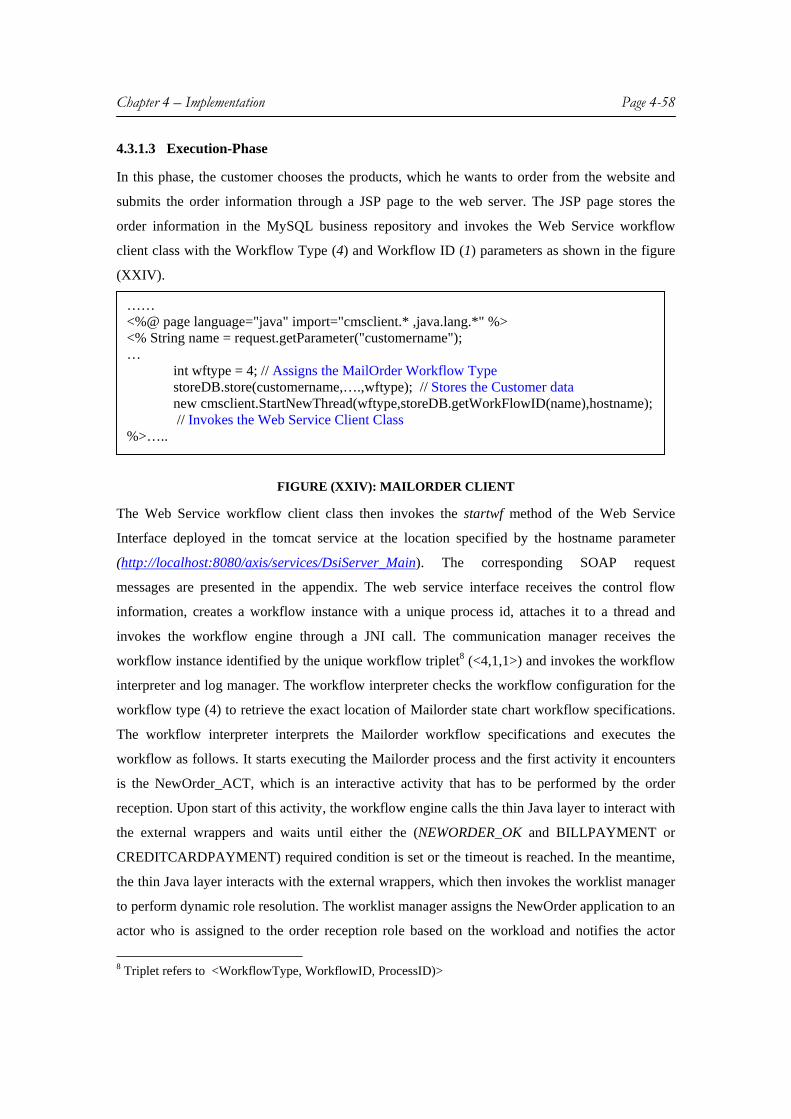
Chapter 4 – Implementation Page 4-58
4.3.1.3 Execution-Phase
In this phase, the customer chooses the products, which he wants to order from the website and
submits the order information through a JSP page to the web server. The JSP page stores the
order information in the MySQL business repository and invokes the Web Service workflow
client class with the Workflow Type (4) and Workflow ID (1) parameters as shown in the figure
(XXIV).
FIGURE (XXIV): MAILORDER CLIENT
The Web Service workflow client class then invokes the startwf method of the Web Service
Interface deployed in the tomcat service at the location specified by the hostname parameter
(http://localhost:8080/axis/services/DsiServer_Main). The corresponding SOAP request
messages are presented in the appendix. The web service interface receives the control flow
information, creates a workflow instance with a unique process id, attaches it to a thread and
invokes the workflow engine through a JNI call. The communication manager receives the
workflow instance identified by the unique workflow triplet8 (<4,1,1>) and invokes the workflow
interpreter and log manager. The workflow interpreter checks the workflow configuration for the
workflow type (4) to retrieve the exact location of Mailorder state chart workflow specifications.
The workflow interpreter interprets the Mailorder workflow specifications and executes the
workflow as follows. It starts executing the Mailorder process and the first activity it encounters
is the NewOrder_ACT, which is an interactive activity that has to be performed by the order
reception. Upon start of this activity, the workflow engine calls the thin Java layer to interact with
the external wrappers and waits until either the (NEWORDER_OK and BILLPAYMENT or
CREDITCARDPAYMENT) required condition is set or the timeout is reached. In the meantime,
the thin Java layer interacts with the external wrappers, which then invokes the worklist manager
to perform dynamic role resolution. The worklist manager assigns the NewOrder application to an
actor who is assigned to the order reception role based on the workload and notifies the actor
8 Triplet refers to <WorkflowType, WorkflowID, ProcessID)>
…… <%@ page language="java" import="cmsclient.* ,java.lang.*" %> <% String name = request.getParameter("customername"); …
int wftype = 4; // Assigns the MailOrder Workflow Type storeDB.store(customername,….,wftype); // Stores the Customer data new cmsclient.StartNewThread(wftype,storeDB.getWorkFlowID(name),hostname);
// Invokes the Web Service Client Class %>…..

Chapter 4 – Implementation Page 4-59
about the new task in the task manager. Figure (XXV) shows the task manager for the actor
steffen who has been assigned to the NewOrder task. The actor then invokes the NewOrder
application by the clicking the reference to the new task url. The actor then validates the customer
data and submits the order by setting the NEWORDER_OK condition to true and the appropriate
Payment mode (BILLPAYMENT/CREDITCARDPAYMENT) to true. As soon as the workflow
engine sees these conditions, it continues execution of the next states depending on the payment
mode selected by the user.
FIGURE (XXV): MENTOR-WS TASK MANAGER FOR WORKFLOW PARTICIPANTS
If the user has selected the credit card as the payment mode, it validates the credit card with the
CreditcardCheck activity and reaches the route activity after successful credit card validation.
The route activity initiates parallel execution of sub-workflows through Notify and Delivery
subflow activities, which sends the notification to customers through mail and ships the order
products to customer respectively. After successful execution of these two sub-workflows the
flow is synchronized and the payment is charged using the credit card information provided by
the customer. The workflow reaches the termination after successful payment transaction
(indicated by PAYMENT_OK condition set to true).

Chapter 4 – Implementation Page 4-60
FIGURE (XXVI): LOGGING INFORMATION OF MAILORDER APPLICATION
The Mentor-WS log manager records all the logging information right from the start of
workflow execution until the termination. The entire logging information is stored in a XML file
(shown in the appendix.), named after the unique workflow instance. This logging information
can be viewed by invoking the log details of the workflow manager GUI. Figure (XXVI) shows
the logging information of the MailOrder application. In the event of a crash, the workflow
Manager GUI can be used to recover from the crash state by invoking the WF recovery. Further,
the workflow manager can be used to know the status of the workflow.
4.4 Summary This chapter discusses the system architecture of the Mentor-WS WfMS based on the system
design presented in the chapter 3. In particular, it describes the implementation of Web-services
as a middleware in the Mentor-WS system. The chapter elucidates how the design goals are
realized in the implementation of Mentor-WS WfMS. In particular, it discusses about the role of
web services in achieving the workflow interoperability and providing a flexible framework for
integration of Mentor-WS WfMS with DeepWeb CMS. It elaborates the functioning of various
open source products such as JaWE and MySQL in the Mentor-WS system and depicts the
Mentor-WS architecture with respect to the reference model architecture of WfMC. The chapter
concludes by discussing the usage of Mentor-WS WfMS based on a sample workflow.

Chapter 5 - Conclusions & Future Work Page 61
CHAPTER 5 CONCLUSION AND FUTURE WORK
Summary This thesis presents our work on achieving workflow interoperability between various types of
organizational workflows through the application of Web Services as a middleware. The thesis
also focuses on integrating the Mentor-WS WfMS with DeepWeb CMS. The thesis starts by
presenting preliminaries, in which workflow terminology, a brief introduction to different process
definition languages, Service oriented architectures, and an overview of both WfMSs and CMSs
have been introduced. Chapter 3 of this thesis presents an overview and evaluation of the existing
system (Mentor-lite). The positive aspects of Mentor-lite include its distributed, scalable, and
persistence nature, while the negative aspects include its inadequate support to offer workflow
interoperability and the usage of commercial products. The most significant limitation of Mentor-
lite is the inadequate support in providing workflow interoperability. Since, Mentor-lite uses a
tightly-coupled CORBA as middleware, it fails to offer adequate support to workflow
interoperability especially in inter-organizational workflows. This critique has lead to the
development of a novel WfMS (Mentor-WS). The major design goals of the novel WfMS include
Workflow interoperability, Integration of the novel WfMS with DeepWeb CMS, Elimination of
commercial products, usage of WfMC Process Definition Language, while preserving the
features of Mentor-lite. Mentor-WS accomplishes the workflow interoperability by replacing the
middleware of Mentor-lite, CORBA, with a more loosely-coupled Web Services framework. It
provides a flexible framework for integration of DeepWeb CMS by the application of Web
Services and the usage of various open source components. Mentor-WS offers support for the
establishment of workflow standards by adopting the standards9 proposed by the WfMC, while
building its system architecture. Mentor-WS uses the process definition language (XPDL)
proposed by WfMC for modeling workflows, which enables it to interpret most of the business
processes modeled using this standard process definition language. Further, Mentor-WS provides
support to platform independency and open source components (unlike Mentor-Lite) making it
highly accessible for users around the world to evaluate it with much ease.
9 Standards refer to the Workflow Reference Model

Chapter 5 - Conclusions & Future Work Page 62
Critique & Future work
The implementation of Mentor-WS has been realized under some limitations and assumptions.
These limitations have been identified and evaluated. As described in chapter 3, preserving the
distributed nature of Mentor-lite is one of the desired goals of Mentor-WS WfMS. Though the
existing Mentor-WS prototype provides support for distributed workflow execution by
preserving10 the state and activity chart workflow specifications, it does not achieve the
distributed nature of Mentor-Lite WfMS. The other limitation of the Mentor-WS WfMS is that
even though the prototype has been built to work on any platform, it has not yet been
implemented and tested on any platform other than windows.
Based on the critique presented above, the possible future enhancements can be identified
as follows: The first enhancement would be to develop an API for achieving distributed execution
of workflows. The API should be capable of generating different workflow instances for
execution by various workflow servers (at different sites) from a given state and activity chart
workflow specification without hampering its semantics. The second enhancement would be to
develop and successfully test the prototype on various platforms other than windows such as
Linux, Solaris etc. The other enhancement would be to provide a more sophisticated and user-
friendly, features for the existing process definition tool (JaWE). The existing process definition
tool (JaWE), can only provide XPDL support for describing information about a particular
application associated with an activity rather than mapping it to a specific application (such as a
JFC class or Java Bean or Java applet etc). Further, application templates (such as send/check
mail, calculate expressions/formulas etc) can be developed for more generic activities of the
workflow. These templates can then be presented at the modeling phase to the user for mapping it
to a particular activity. This approach provides a more user-friendly, flexible, and reusable
process definition framework to the user.
10 State and activity chart representations provide support for distributed workflow execution [DG97]

Appendix Page 63
APPENDIX This section provides a technical overview of the Mentor-WS WfMS. Section A.1 presents the
package hierarchy and outlines the classes associated with each package. The section also
provides some code snippets to illustrate the usage of important methods in the package. Section
A.2 presents the essential libraries that have to be included in the Mentor-WS WfMS, while
section A.3 describes the database schemas. Section A.4 concludes this chapter by stating the
system requirements.
A.1 Mentor-WS Module Structure The Mentor-WS module comprises of four main packages as illustrated in figure (XXVII).
ORG MENTOR DSISERVER EXTWRAPPERS WORKFLOW JAWEMENTOR LIB
FIGURE (XXVII): MENTOR-WS PACKAGE HIERARCHY
A.1.1 DSISERVER
This package contains all classes and interfaces needed for implementing the thin Java layer
which acts as a Web Service interface for clients and as a gateway between mentor workflow
engine and external wrappers. This package also contains classes for establishing database
communication and registering workflow objects using JNDI registry. Table 1 presents all the
classes in this package and important methods in each class. The DsiServer_i interface defines all
methods needed for implementing Web Services. The DsiServer class implements the above
stated interface and provides the Mentor-WS Workflow functionality to the clients. The four
important methods in this package are depicted in the figure (XXVIII).
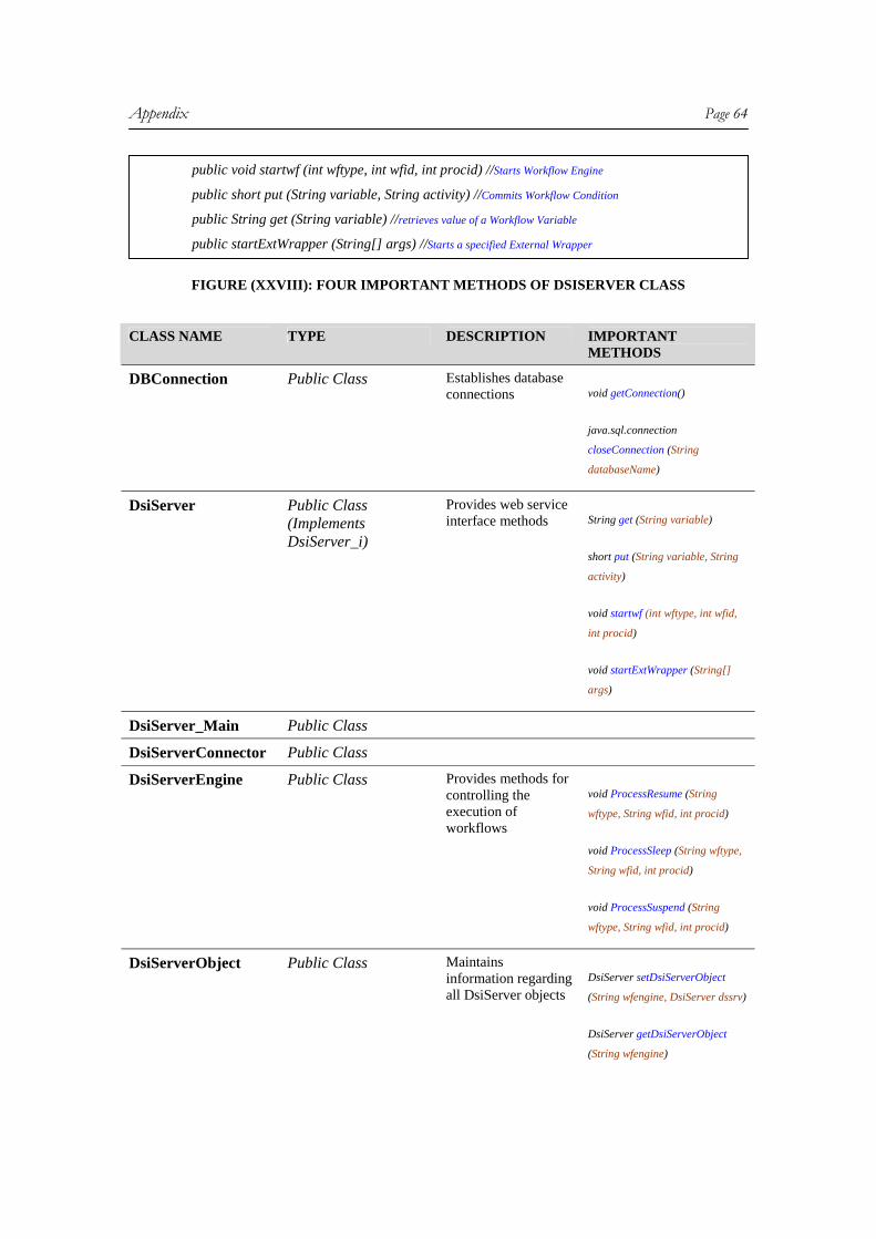
Appendix Page 64
FIGURE (XXVIII): FOUR IMPORTANT METHODS OF DSISERVER CLASS
CLASS NAME TYPE DESCRIPTION IMPORTANT
METHODS
DBConnection Public Class Establishes database connections void getConnection()
java.sql.connection
closeConnection (String
databaseName)
DsiServer Public Class (Implements DsiServer_i)
Provides web service interface methods
String get (String variable)
short put (String variable, String
activity)
void startwf (int wftype, int wfid,
int procid)
void startExtWrapper (String[]
args)
DsiServer_Main Public Class
DsiServerConnector Public Class
DsiServerEngine Public Class Provides methods for controlling the execution of workflows
void ProcessResume (String
wftype, String wfid, int procid)
void ProcessSleep (String wftype,
String wfid, int procid)
void ProcessSuspend (String
wftype, String wfid, int procid)
DsiServerObject Public Class Maintains information regarding all DsiServer objects
DsiServer setDsiServerObject
(String wfengine, DsiServer dssrv)
DsiServer getDsiServerObject
(String wfengine)
public void startwf (int wftype, int wfid, int procid) //Starts Workflow Engine
public short put (String variable, String activity) //Commits Workflow Condition
public String get (String variable) //retrieves value of a Workflow Variable
public startExtWrapper (String[] args) //Starts a specified External Wrapper

Appendix Page 65
DsiServer lookupDsiServer
(String wfengine)
DsiServerPut Public Class Commits conditions into workflow engine void putinMentor (int actorid,
String actname, String variable)
DsiServer_i Interface
MentorFactory Public Class Provides methods for retrieving workflow objects from JNDI registry
Object getobjectInstance (Object
obj ,javax.naming.Name name,
javax.naming.Context ctx,
java.util.Hashtable env)
RegisterObject Public Class javax.naming.Reference
getReference ()
Util Public Class int getProcID (int wftype)
TABLE 1 Class Summary for ORG.MENTOR.DSISERVER package
A.1.2 EXTWRAPPERS
This package contains classes, which provide functionality needed for interacting with external
wrappers. The package consists of two main classes. Table 2 presents these two classes and
important methods associated with it. The ExtWrappers class invokes the specified application
wrapper, while the TimeOuts class keeps track of the timeouts. The startExtWrapper method is
the most important of all the methods in this package. This method invokes the specified
application wrapper using the Java reflection API as shown in the figure (XXIX).
public static void startExtWrapper(String args[]) { Integer WFTY = new Integer(args[0]); Integer WFID = new Integer(args[1]); Integer PROC = new Integer(args[2]); paramTypes = new Class[] {DsiServer.class,WFTY.getClass(),WFID.getClass(),PROC.getClass()}; …
obj = (Object) Class.forName ("org.mentor.mentorExtWrappers."+packname.toUpperCase() +"."+ actname.toUpperCase()).newInstance();
…. DsiServer dssrv = DsiServerObject.getDsiServerObject(wfengine);
Object[] inargs= new Object[] {dssrv,WFTY,WFID,PROC}; methd = obj.getClass().getMethod("startWrapper", paramTypes); methd.invoke(obj, inargs); // Invokes the startWrapper method of the specified Activity class …. } // with DsiServerObject, workflow Type, workflow ID & process ID as parameters.

Appendix Page 66
FIGURE (XXIX): CODE SNIPPET FOR EXTWRAPPERS CLASS
CLASS NAME TYPE DESCRIPTION IMPORTANT METHODS
ExtWrappers Public Class Provides Interaction with application wrappers
static void checkMentorStatus()
static void startExtWrapper (String[] args)
TimeOuts Public Class Maintains workflow Timeouts
boolean checkStatus (String cond)
void checkTimeOuts (String cond)
boolean getStatus()
void setTimeOuts (String activity, int days)
TABLE 2 Class Summary for ORG.MENTOR.EXTWRAPPER package
A.1.3 WORKFLOW
This package contains all classes and interfaces needed for implementing the GUI based
Workflow manager, which includes the worklist manager, statechart viewer, statechart converter,
control flow viewer, log and recovery managers. The package also contains classes, which
maintain information regarding the statechart workflow specifications, information and status of
the workflow engine. Table 3 presents the class summary for this package while the important
methods are listed in the figure (XXX).
FIGURE (XXX): IMPORTANT METHODS OF WORKFLOW PACKAGE CLASS NAME TYPE DESCRIPTION IMPORTANT
METHODS
DrawImage Public Class Draws an image at the centre of a frame void DrawImage (String
imagefile)
ImageLoader Public Class Utility class for loading images static void setComponent
(java.awt.Component component)
WFInfoXML Public Class Provides basic functions void insertElemsIntoXML
public void suspendWFEngine (String wfengine) // Suspend Workflow Execution public void wfRecovery(String xmlfile) // Perform Workflow Recovery //Assign Roles to Actors public void setActorToRoleName (String actorName, String roleName, String wfType) //Assign workitems to Actors public void assignWorkToActors (String actname, int priority, String rolename, String href) public String getLogFile() // Retrieve Workflow Log File

Appendix Page 67
for interacting with log files in XML
(String actname, String variable , String str)
void writeToFile (String fname, org.jdom.Document Doc)
WFManager Public Class This class generates a frame with overall information about the workflow system
void setTextArea (java.awt.TextArea logInfo)
WLManager Public Class This class generates a frame with the information about the worklist management of a WFMS
WorkFlow Public Class Maintains basic Information about workflows
void setAuthor (String author)
void setBackupVersionNumber (String backup)
void setConfigVersionNumber (String cfgversion)
WorkFlowAction Public Class Provides functionality for controlling workflow execution
short putVariableValue (String variable,String activity)
void startwf (int wftype, int wfid, int procid)
void suspendWFEngine (String wfengine)
WorkFlowActivity Public Class Maintains Information about all workflow activities
void setName (String name)
void setImplementedBy (String impl)
void getName ()
WorkFlowActor Public Class Maintains Information about all workflow actors int getActorID()
String getActorName()
int getWorkLoad()
WorkFlowArrow Public Class Maintains Information about all workflow arrows void setSource (String source)
void setTarget (String target)
void setLabel (String label)
WorkFlowChart Public Class Maintains header Information about all workflow charts
void setName (String name)

Appendix Page 68
void setCreator (String creator)
void getName ()
WorkFlowCondition Public Class Maintains Information about all workflow actors void setName (String name)
void setDataStructure (String data_structure)
void getName ()
WorkFlowConfigFiles Public Class Maintains configuration details about all workflow specification files
void WorkFlowConfigFiles (String wftype, String packagename, String processname)
WorkFlowConnector Public Class Maintains Information about all workflow connectors
void setName (String name)
void setParent (String parent)
void getName ()
WorkFlowDataItem Public Class Maintains Information about all workflow dataitems
void setName (String name)
void setDataType (String data_type)
void getName ()
WorkFlowEntity Public Class Maintains Information about all workflow entities
void setName (String name)
void setEntityId (String entityid)
void getName ()
WorkFlowFiles Public Class Reads workflow files in state & activity chart formats
String getLogFile()
String getWFConfigFile()
WorkFlowInfo Public Class This class provides information about all workflow specifications
java.util.Hashtable getAllProcesses()
java.util.Hashtable getAllStates(int processId)
WorkFlowModule Public Class Maintains Information about all Module chart specifications
void setName (String name)
void setType (String type)
void getName ()

Appendix Page 69
WorkFlowProcess Public Class Maintains Information about all processes defined in the workflow
void setName (String name)
void setProcid (String procid)
void getName ()
WorkFlowRole Public Class Maintains Information about all roles defined in a workflow process
void setName (String name)
void setRoleId (String roleid)
void getName ()
WorkFlowSetInfo Public Class (Implements WorkFlowInfo_i)
Sets workflow process Configuration void WorkFlowSetInfo (String
wfConfigFile)
void setProcessInfo (WorkFlowProcess wfp)
void setChartInfo (WorkFlowChart wc, String filename)
WorkFlowState Public Class Maintains Information about all states defined in a workflow process
void setName (String name)
void setSubWorkFlow (String is)
void getName ()
WorkFlowStatus Public Class (implements WorkFlowStatus_i)
Provides workflow status WorkFlowProcess getCurrentProcess (int ProcessId)
WorkFlowState getCurrentState (String filename)
Vector wfActivity_Recovery (String filename)
void wfRecovery(String xmlfile)
WorkListManager Public Class Provides WorkList Manager functionality void setActorToRoleName
(String actorName, String roleName, String wfType)
void addRoles (String roleId, String roleName,int wftype)
void assignWorkToActors (String actname, int priority, String rolename, String href)
void updateWorkLoad (int actorId)

Appendix Page 70
WorkFlowInfo_i Interface Provides methods for retrieving workflow information
WorkFlowStatus_i Interface Provides methods for retrieving status of workflow.
Table 3 Class Summary for ORG.MENTOR.WORKFLOW package
A.1.4 JAWEMENTOR
This package consists of classes (as listed in Table 4) that enable the conversion of workflow
specifications in XPDL modeled using JaWE to an intermediate state and activity chart workflow
specifications. The package consists of two interfaces namely JaWEInf and JaWEMentorInf,
which define methods for parsing XPDL file and converting the XPDL into state and activity
chart representations. The parseXpdl class of this package implements the JaWEInf interface,
thereby providing the functionality required for parsing a XPDL file using the JDOM API. The
JaWEMentor class implements the JaWEMentorInf interface, thereby enabling the conversion of
XPDL. The important methods in this package are depicted in the figure (XXXI)
FIGURE (XXXI): IMPORTANT METHODS OF JAWEMENTOR PACKAGE CLASS NAME TYPE DESCRIPTION IMPORTANT
METHODS
ErrorClass Public Class Provides Error information String getErrorDescription()
String getErrorNumber()
JaWEMentor Public Class (Implements JaWEMentorInf)
Provides Conversion of XPDL workflow specification to State and activity representation
void JaWEMentor
(String XpdlSource)
void convert()
JaWEMentorActivity Chart
Public Class Builds Activity Charts from XPDL workflow specifications
void JaWEMentorActivityChart
(String XpdlSource,
String ProcessId)
public void convert() //Converts the XPDL file public void ErrorClass[] ValidateWF (String sourceXPDL, String sourceProcess,
boolean DebugMode) //Validates the XPDL file for errors public java.util.Vector getSourceProcess() //Detects the Source(Main) process from the XPDL file public java.util.Vector getSubFlows (String WorkFlowProcess) //Retrieves the Subworkflows of the
// source process

Appendix Page 71
JaWEMentorConfig Public Class Builds Mentor configuration from XPDL workflow specifications
void JaWEMentorConfig
(String XpdlSource
String SourceProcess)
JaWEMentorModule Chart
Public Class Builds Module Charts from XPDL workflow specifications
void JaWEMentorModuleChart
(String XpdlSource,
String SourceProcess)
JaWEMentorState Chart
Public Class Builds State Charts from XPDL workflow specifications
void JaWEMentorStateChart
(String XpdlSource,
String ProcessId)
ValidateJaWEWF Public Class Validates the XPDL workflow Specifications with reference to State & Activity chart specifications
void ErrorClass[] ValidateWF
(String sourceXPDL,
String sourceProcess,
boolean DebugMode)
JaWEMentorInf Interface Class Provides methods for conversion of XPDL to state & activity chart format
JaWEInf Interface Class Provides Interface methods for parsing XPDL workflow specifications
Activity Public Class Maintains Information about various activities defined in a XPDL workflow specification
String getActivityId()
void setSubFlowID
(String SWFlowID)
void setImplementationType
(String IType)
Connector Public Class Maintains Information about various connectors defined in a XPDL workflow specification
void setConnectActivity
(String ConnAct)
void setConnectorType
(String ConnType)
DataField Public Class Maintains Information about various datafields defined in a XPDL workflow specification
void setDataFieldName
(String DFName)
void setIsArray (String Isarray)

Appendix Page 72
ParseXpdl Public Class (Implements JaWEInf)
Reads and parses XPDL files using JDOM
java.util.Vector getSourceProcess()
Participant[] getParticipants()
java.util.Vector
getWorkflowProcesses()
java.util.Vector getSubFlows
(String WorkFlowProcess)
Participant Public Class Maintains Information about various participants defined in a XPDL workflow specification
String getParticipantId()
String getParticipantName()
String setParticipantType(String
PType)
ProcessInfo Public Class Maintains Information about various processes defined in a XPDL workflow specification
String getFormalParameterMode()
String getFormalParameterType()
void setFormalParameterID
(String FormalParameterID)
Transition Public Class Maintains Information about various transitions defined in a XPDL workflow specification
String getSourceActivity()
String getTargetActivity()
String getTransitionID()
Table 4 Class Summary for ORG.MENTOR.JAWEMENTOR package
A.2 Library Dependencies The libraries listed in Table 5 are needed in your CLASSPATH or installation directory lib
directory.
LIBRARY NAME
DEPENDENCIES DESCRIPTION AVAILABLE AT
Apache AXIS axis.jar, axis-ant.jar, commons-discovery.jar, commons-logging.jar, log4j-
Needed for Implementing Web Services Framework
http://apache.easy-webs.de/ws/axis/1_1/axis-1_1.zip

Appendix Page 73
1.2.8.jar, jaxrpc.jar, saaj.jar, wsdl4j.jar
MySQL 4.1 mysql-connector-java-3.0.10-stable-bin.jar
Needed For establishing communication with MySQL Databases
http://dev.mysql.com/downloads/mysql/4.1.html
JNDI fscontext.jar, providerutil.jar
Needed for accessing JNDI registry for storing mentor objects
http://java.sun.com/j2ee/1.4/download.html#sdk
JDOM jdom.jar Needed for Parsing XPDL files and writing log information into XML files
http://www.jdom.org/dist/binary/jdom-1.0.zip
DeepWebCMS Deepwebcms.jar Needed for integrating Mentor-WS with DeepWeb CMS
Provided at org/lib folder
Mentor-WS DsiServer_main.dll,DsiServer_main.lib
Needed for interacting with mentor-ws workflow engine (core)
Provided at org/lib folder
JNI jni.h, jvmdi.h ,jvmpi.h, jni_md.h
Needed for JNI calls to C Provided at /include folder of your <JDK> installation
Table 5 Essential Libraries for MENTOR-WS
A.3 Database Schemas CREATE TABLE ACT2URL ( activityname VARCHAR(40) NOT NULL DEFAULT '', href VARCHAR(255) NOT NULL DEFAULT '', PRIMARY KEY ( activityname , href ) ); CREATE TABLE ACTIVITY ( username VARCHAR(40) NOT NULL DEFAULT '', name VARCHAR(40) DEFAULT NULL, customer VARCHAR(40) DEFAULT NULL, description VARCHAR(40) DEFAULT NULL, wftype INT(11) DEFAULT NULL, wfid INT(11) DEFAULT NULL, procid INT(11) DEFAULT NULL, priority INT(3) DEFAULT NULL, start_time DATE DEFAULT NULL, deadline DATE DEFAULT NULL, status VARCHAR(10) DEFAULT NULL, href VARCHAR(255) NOT NULL DEFAULT '', PRIMARY KEY ( username , href )

Appendix Page 74
); CREATE TABLE ACTIVITY_TMP ( count INT(8) NOT NULL DEFAULT '0', actorname VARCHAR(40) DEFAULT NULL, activityname VARCHAR(40) DEFAULT NULL, workflow_type INT(38) NOT NULL DEFAULT '0', workflow_id INT(38) NOT NULL DEFAULT '0', PRIMARY KEY ( count , workflow_type , workflow_id ) ); CREATE TABLE ACTORS ( id INT(10) NOT NULL DEFAULT '0', name VARCHAR(40) DEFAULT NULL, status VARCHAR(40) DEFAULT NULL, workload INT(10) DEFAULT NULL, Email VARCHAR(20) NOT NULL DEFAULT '', PRIMARY KEY ( id ) ); CREATE TABLE ENVIRON_VARS ( mlite_home VARCHAR(30) NOT NULL DEFAULT '', jawe_home VARCHAR(30) NOT NULL DEFAULT '', jndi_registry VARCHAR(30) NOT NULL DEFAULT '' ); CREATE TABLE PLAYSROLE ( actorID INT(10) NOT NULL DEFAULT '0', role_name VARCHAR(20) NOT NULL DEFAULT '', wftype INT(11) NOT NULL DEFAULT '0', PRIMARY KEY ( actorID , role_name , wftype ) ); CREATE TABLE ROLES ( roleid INT(3) NOT NULL DEFAULT '0', rolename VARCHAR(20) NOT NULL DEFAULT '', wftype INT(11) NOT NULL DEFAULT '0' ); CREATE TABLE USERS ( name VARCHAR(30) NOT NULL DEFAULT '', email VARCHAR(30) NOT NULL DEFAULT '', passwd VARCHAR(30) NOT NULL DEFAULT '', status INT(11) NOT NULL DEFAULT '0', wftype INT(11) NOT NULL DEFAULT '0', wfid INT(11) NOT NULL AUTO_INCREMENT, procid INT(11) NOT NULL DEFAULT '0', PRIMARY KEY ( wfid ) );

Appendix Page 75
CREATE TABLE WFENGINE ( wftype INT(11) NOT NULL DEFAULT '0', wfid INT(11) NOT NULL AUTO_INCREMENT, procid INT(11) NOT NULL DEFAULT '0', starttime VARCHAR(20) NOT NULL DEFAULT '', endtime VARCHAR(20) NOT NULL DEFAULT '', PRIMARY KEY ( wftype , wfid , procid ) ) CREATE TABLE WFPACKAGES ( ID INT(11) NOT NULL DEFAULT '0', packagename VARCHAR(30) NOT NULL DEFAULT '', xpdlfile VARCHAR(50) NOT NULL DEFAULT '', processid INT(11) NOT NULL DEFAULT '0', PRIMARY KEY ( ID ) ); CREATE TABLE WFTIMEOUTS ( wftype INT(11) NOT NULL DEFAULT '0', wfid INT(11) NOT NULL DEFAULT '0', procid INT(11) NOT NULL DEFAULT '0', id INT(11) NOT NULL AUTO_INCREMENT, activity VARCHAR(20) NOT NULL DEFAULT '', begin DATE DEFAULT NULL, end DATE DEFAULT NULL, PRIMARY KEY (wftype, wfid, procid ,id) ); CREATE TABLE WFACTIVITY ( actorname VARCHAR(40) NOT NULL DEFAULT '0', activityname VARCHAR(40) NOT NULL DEFAULT '0', customer VARCHAR(40) NOT NULL DEFAULT '0', description VARCHAR(80) NOT NULL AUTO_INCREMENT, wftype INT(11) NOT NULL DEFAULT '', wfid INT(11) DEFAULT NULL, procid INT(11) DEFAULT NULL, priority INT(3) DEFAULT NULL, starttime DATE DEFAULT NULL, deadline DATE DEFAULT NULL, status VARCHAR(20) DEFAULT NULL, href VARCHAR(50) DEFAULT NULL, PRIMARY KEY (wftype, wfid, procid) );

Appendix Page 76
A.4 SOAP Messages & XML Logs
FIGURE (XXXII): SOAP REQUEST MESSAGE
FIGURE (XXXIII): XML WORKFLOW LOG
A.5 System Requirements
The current version of Mentor-WS prototype has been successfully tested on Windows XP
professional edition. Table 6 lists the softwares that have to be installed along with the dependent
libraries listed in table 5 for successful installation of Mentor-WS prototype. The prototype can
<SOAP-ENV:Envelope xmlns:SOAP-ENV="http://schemas.xmlsoap.org/soap/envelope/"
xmlns:xsi="http://www.w3.org/1999/XMLSchema-instance"
xmlns:xsd="http://www.w3.org/1999/XMLSchema">
<SOAP-ENV:Header />
<SOAP-ENV:Body>
<ns1:startwf xmlns:ns1="http://localhost:8080/DsiServer_Main"
SOAP-ENV:encodingStyle="http://schemas.xmlsoap.org/soap/encoding/">
<wftype xsi:type="xsd:string"> 4 </wftype>
<wfID xsi:type="xsd:string"> 1 </wfID>
</ns1:startwf>
</SOAP-ENV:Body>
</SOAP-ENV:Envelope>
<?xml version="1.0" encoding="UTF-8" ?> <WorkFlowProcess> <Activity name="NEWORDER_ACT" status="complete"> <Variable name="NEWORDER_OK=1" /> <Variable name="CREDITCARDPAYMENT=1" /> </Activity> <Activity name="CREDITCARDCHECK_ACT" status="complete"> <Variable name="CREDITCARDCHECK_OK=1" /> <Variable name="CREDITCARDOK=1" /> </Activity> <Activity name="PROCESSORDER_ACT" status="complete"> <Variable name="NOTIFY_OK=1" /> <Variable name="DELIVERED_OK=1" /> </Activity> <Activity name="PROCESSORDER_ACT" status="complete"> <Variable name="CREDITCARDPAY=1" /> </Activity> <Activity name="CREDITCARDCHARGE_ACT" status="complete"> <Variable name="CREDITCARDCHARGE_OK=1" /> </Activity> </WorkFlowProcess>

Appendix Page 77
be installed on any system, which has a minimum processing speed of 400 MHz (Pentium
Celeron/II/III or AMD K6/K7) along with 128 MB (RAM) memory and atleast 200 MB of free
space.
Software Title
Version Platform Description Available at
Java J2SE 1.4.2
Windows http://java.sun.com/j2se/1.4.2/download.html
JaWE 1.3 Windows Workflow Modeling tool
http://jawe.objectweb.org/
MySQL 4.1.4 -gamma
Windows Database http://dev.mysql.com/downloads/mysql/4.1.html
Tomcat 4.1.6 Windows Standalone Web Server
http://jakarta.apache.org/site/binindex.cgi
Apache HTTP Server
1.3 Windows HTTP Server
http://httpd.apache.org/download.cgi
Table 6 Software Requirements for MENTOR-WS

Bibliography Page 78
BIBLIOGRAPHY
[Aal94] W.M.P. van der Aalst. Putting Petri nets to work in industry. Computers in Industry, 25(1):45–54, 1994.
[ACK+04] Alonso, G., Casati, F., Kuno, H., Machiraju, V. Web ServicesConcepts, Architectures and Applications, Springer Verlag, 2004.
[Ati01] Atila Kaya, Workflow Interoperability: The WfMC Reference Model and an Implementation, Master Thesis, Technical University Hamburg, Hamburg, 2001.
[Dav95] David Hollingsworth. The Workflow Reference Model, Workflow Management Coalition, 1995.
[DG97] D. Wodtke, Gerhard Weikum: A Formal Foundation For Distributed Workflow Execution Based on State Charts, International Conference on Database Theory (ICDT), Delphi, Greece, 1997.
[GMG02] German Shegalov, Michael Gillmann, Gerhard Weikum: XML-enabled Workflow Management for E-Services across Heterogeneous Platforms, 2002.
[GWS+2000] Gillmann, M., Weissenfels, J., Shegalov, G., Wonner, W., Weikum, G.: A Goal driven AutoConfiguration Tool for the Distributed Workflow Management System Mentor-lite. In Proc. of ACM SIGMOD Conf. on Management of Data (SIGMOD), Dallas, Texas, 2000
[Han2001] Hannon Hill Corporation. Workflow in a Content Management System, White Paper, Atlanta, 2001.
[Has03] Syed Hashimi. Service-Oriented Architectures Explained, http://www.ondotnet.com, 2003.
[HC94] Hammer, M., Champy, J. Re-Engineering the Corporation. A Manifesto for Business Revolution. Addison-Wesley, 1994.
[Hee94] K.M. van Hee. Information System Engineering: a Formal Approach. Cambridge University Press, 1994.
[Her02] Herzum, P.: Web Services and Service-Oriented Architectures. Executive Report, Vol.4, no.10. Cutter Distributed Enterprise Architecture Advisory Service, 2002.
[HL91] K. Hayes and K. Lavery. Workflow management software: the business opportunity. Technical report, Ovum Ltd, London, 1991.
[JB96] Jablonski S., Bussler C. Workflow Management. Modeling Concepts

Bibliography Page 79
Architecture and Implementation, International Thomson Computer Press, 1996.
[Jen96] K. Jensen. Coloured Petri Nets. Basic concepts, analysis methods and practical use. EATCS monographs on Theoretical Computer Science. Springer-Verlag, Berlin, 1996.
[Jon00] Jon Pyke, What’s happened to Workflow? Article, www.staffware.com, 2000.
[Kei99] Keith Edwards, W .: Core JINI, Prentice Hall, June 28 1999.
[Kou95] T.M. Koulopoulos. TheWorkflow Imperative. Van Nostrand Reinhold, New York, 1995.
[Law97] P. Lawrence, editor. Workflow Handbook 1997, Workflow Management Coalition. John Wiley and Sons, New York, 1997.
[Man04] Manoj Seth, Introduction to Web Services Management, Article, www.developer.com , 2004.
[MWG+98] P.Muth, D. Wodtke, J. Wiessenfels, G. Weiku, A. Kotz Dittrich.: Enterprise-wide Workflow Management based on State and Activity Charts, NATO Advanced Study Institute, Springer, 1998.
[MWW+98] P.Muth, D. Wodtke, J. Wiessenfels, A. Kotz Dittrich, G. Weikum.: From Centralized Workflow Specification to Distributed Workflow Execution, Journal of Intelligent Information Systems, Special Issue on Workflow Management, Vol. 10, No. 2, 1998.
[Nik04] Mehran Nikoo. Adoption of Service-Oriented Architecture (SOA) in Software Development, CSIS Research Day, June 30, 2004.
[Pal01] Micheal S. Pallos. Service-Oriented Architecture: A Primer, eAI Journal, December 2001.
[PM01] Paul Browning, Mike Lowndes. Content Management Systems, A JISC TechWatch Report, 2001.
[RD97] Reichert, M., Dadam, P. A Framework for Dynamic Changes in Workflow Management Systems. Proc. 8th International Workshop on Database and Expert Systems Applications 1997, pp 42-48. Los Alamitos: IEEE Computer Society Press 1997.
[RD98] Reichert, M., Dadam, P. Supporting Dynamic Changes of Workflows without Loosing Control. Journal of Intelligent Information Systems, Special Issue on Workflow and Process Management, Vol. 10, No.2, 1998.
[RRD03] Manfred Reichert, Stefanie Rinderle, and Peter Dadam. ADEPT Workflow Management System: Flexible Support for Enterprise-Wide Business Processes,

Bibliography Page 80
Tool Presentation, 2003.
[RS03] Rutger Engelhard, Sebastiaan van de Vliet. Content Management Systems, Dev Articles, 2003.
[SCH99] Scheer, A.-W. ARIS - Business Process Frameworks (3rd Ed). Springer, 1999.
[Wes99] Weske, M. Formal Foundation, Conceptual Design, and Prototypical Implementation of Workflow Management Systems, Dissertation, University of Munster, Munster, 1999.
[WfMC02] Mike Marin, Roberta Norin and Robert Shapiro. Workflow Process Definition Interface -- XML Process Definition Language, Document Number: WFMC-TC-1025. Document Status: 1.0 Final Draft. October 25, 2002.
[WfMC94b] Workflow Management Coalition, “Glossary: A Workflow Management Coalition Specification”, Workflow Management Coalition Standard, WfMC-TC-1011, 1994.
[WfMC95] Workflow Management Coalition, “The Workflow Management Reference Model”, Workflow Management Coalition Standard, WfMC-TC00-1003, 1995.
[WGR+00] Jeanine Weissenfels, Michael Gillmann, Olivier Roth, German Shegalov, Wolfgang Wohner.: The Mentor-lite Prototype: A Light-Weight Workflow Management System (Demo Description), 16th International Conference on Data Engineering, San Diego, CA, USA, 2000.
[WWW+00] Jeanine Weissenfels, Dirk Wodtke, Gerhard Weikum, Angelika Kotz Dittrich. The Mentor Architecture for Enterprise-wide Workflow Management, 2000.
[WWW+96] D. Wodtke, J. Weissenfels, G. Weikum, A. Kotz Dittrich. The Mentor Project: Steps Towards Enterprise-Wide Workflow Management, IEEE International Conference on Data Engineering, New Orleans, 1996.