A homography formulation to the 3pt plus a common ...
15
HAL Id: hal-01081422 https://hal.archives-ouvertes.fr/hal-01081422 Submitted on 7 Nov 2014 HAL is a multi-disciplinary open access archive for the deposit and dissemination of sci- entific research documents, whether they are pub- lished or not. The documents may come from teaching and research institutions in France or abroad, or from public or private research centers. L’archive ouverte pluridisciplinaire HAL, est destinée au dépôt et à la diffusion de documents scientifiques de niveau recherche, publiés ou non, émanant des établissements d’enseignement et de recherche français ou étrangers, des laboratoires publics ou privés. A homography formulation to the 3pt plus a common direction relative pose problem Olivier Saurer, Pascal Vasseur, Cedric Demonceaux, Friedrich Fraundorfer To cite this version: Olivier Saurer, Pascal Vasseur, Cedric Demonceaux, Friedrich Fraundorfer. A homography formulation to the 3pt plus a common direction relative pose problem. 12th Asian Conference on Computer Vision, Nov 2014, Singapore, Singapore. hal-01081422
Transcript of A homography formulation to the 3pt plus a common ...

HAL Id: hal-01081422https://hal.archives-ouvertes.fr/hal-01081422
Submitted on 7 Nov 2014
HAL is a multi-disciplinary open accessarchive for the deposit and dissemination of sci-entific research documents, whether they are pub-lished or not. The documents may come fromteaching and research institutions in France orabroad, or from public or private research centers.
L’archive ouverte pluridisciplinaire HAL, estdestinée au dépôt et à la diffusion de documentsscientifiques de niveau recherche, publiés ou non,émanant des établissements d’enseignement et derecherche français ou étrangers, des laboratoirespublics ou privés.
A homography formulation to the 3pt plus a commondirection relative pose problem
Olivier Saurer, Pascal Vasseur, Cedric Demonceaux, Friedrich Fraundorfer
To cite this version:Olivier Saurer, Pascal Vasseur, Cedric Demonceaux, Friedrich Fraundorfer. A homography formulationto the 3pt plus a common direction relative pose problem. 12th Asian Conference on Computer Vision,Nov 2014, Singapore, Singapore. �hal-01081422�
A homography formulation to the 3pt plus a
common direction relative pose problem
Olivier Saurer1, Pascal Vasseur2, Cedric Demonceaux3, and FriedrichFraundorfer4
1ETH Zurich, Switzerland2LITIS - Universite de Rouen, France
3Le2i, UMR CNRS 6306 Universite de Bourgogne, France4Remote Sensing Technology, Technische Universitat Munchen, Germany
Abstract. In this paper we present an alternative formulation for theminimal solution to the 3pt plus a common direction relative pose prob-lem. Instead of the commonly used epipolar constraint we use the homog-raphy constraint to derive a novel formulation for the 3pt problem. Thisformulation allows the computation of the normal vector of the planedefined by the three input points without any additional computation inaddition to the standard motion parameters of the camera. We show theworking of the method on synthetic and real data sets and compare it tothe standard 3pt method and the 5pt method for relative pose estima-tion. In addition we analyze the degenerate conditions for the proposedmethod.
1 Introduction
Reducing the number of required points to be matched or to be tracked in orderto estimate the egomotion of a visual system can be very interesting in termsof computation time efficiency and of robustness improvement. In the case ofan uncalibrated camera, eight points are at least necessary for estimating thefundamental matrix [1] while only five are sufficient in the calibrated case forthe essential matrix [2]. It appears clearly that this point number reduction isonly possible if some hypotheses or supplementary data are available. For exam-ple, some recent works proposed to use only one point to perform a structurefrom motion method [3] by supposing a non-holonomic motion or to estimatethe metric velocity of a single camera [4] in combining with accelerometer andattitude measurements.
In our method, we propose to use a known common direction between twoimages. Thus, this knowledge of a common direction reduces the number of rota-tions from three to one. Obtaining a common direction can be performed eitherby the use of an IMU (Inertial Measurement Unit) or by some information ex-tracted from the images such as vanishing points or horizon. IMUs are nowadaysused in many devices such as smart phones or robotic platforms. The couplingwith a camera is then very easy and can then be used for different computer vi-sion tasks [5–9]. However, even if a complete rotation is available from an IMU,
2 Authors Suppressed Due to Excessive Length
it appears nevertheless that the heading is generally less accurate than the twoother angles [10]. Let us note, in the case of a pure vision approach (withoutexternal sensor), this common direction can be obtained by one vanishing pointin man made environment [11] or by the detection of the horizon line [12] in thecase of natural scene.
Recently, it has been shown that only three points are needed to computethe pose between two cameras if we know a common direction [10, 13, 14]. Thismethod derives the epipolar constraint to compute the essential matrix with only3 degrees of freedom. In this paper we propose to use the homography constraintbetween two views. We show, contrary to the general case where 4 points areneeded, that we can compute the pose with only 3 matching points. Let us note,as we need only 3 points in the scene, our method works even if these 3D pointsdo not belong physically to the same plane. Thus the derived formulation usingthe homography constraint can be used in the same settings as the standard 3ptmethod using the epipolar constraint.
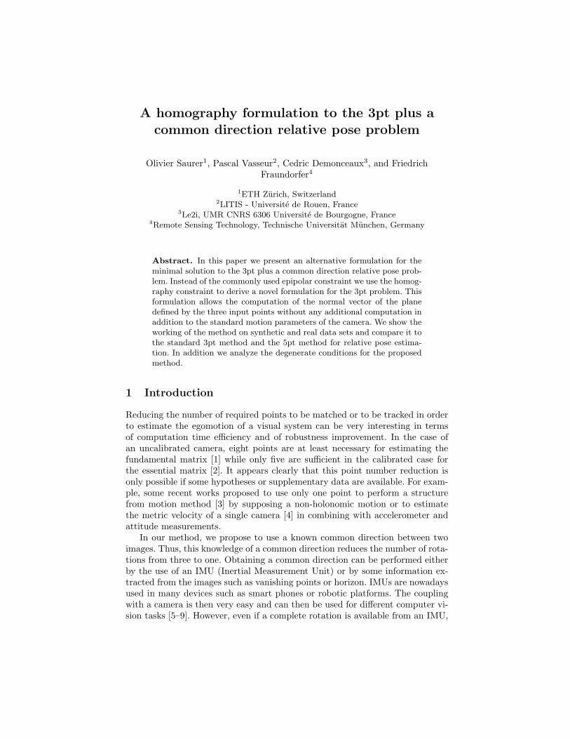
Moreover, if we assume the existence of a dominant plane in the scene, ourmethod can be included in a RANSAC process in order to estimate the normalof the plane and the pose of the cameras in presence of noise. Compared to theclassical algorithm of homography estimation which needs 4 points, we use only3 points and thus allows to decrease the number of iterations in the RANSAC.Indeed, as presented in Figure 1, for a probability of success of 0.99 and a rateof outliers equal to 0.5, the number of trials is divided by two for a robustimplementation with RANSAC compared to the 4 points algorithm. Using theco-planarity constraint in order to simplify the SFM problem is not new [15][16].Moreover, if we know roll and pitch of the camera, Saurer et al. [17] prove thatwe need only 2 points to estimate the full pose of the camera if we also knowthe normal of the plane. In this paper, we show that only 3 points are needed ifroll and pitch angles are known and if the normal is unknown.
2 Related Works
When the camera is not calibrated, at least 8 points are needed to recover themotion [1]. It’s now well known that, if this camera is calibrated, only 5 featurepoints in the scene can be sufficient. Reducing this number of points can bevery interesting in order to reduce the computation time and to increase therobustness. To do this, we have to add some hypotheses about the motion of thecamera, on the extracted feature points or use supplementary sensors.
For example, if all the 3D points belong on a plane, we need a minimum of 4points to estimate the motion of the camera between two-views [1]. On the otherhand, if the camera is embedded on a mobile robot which moves on a planarsurface we need 2 points to recover the motion [18] and if moreover the mobilerobot has non-holonomic constraints only one point is necessary [3]. In the sameway, if the camera moves in a plane perpendicular to the gravity, Troiani et al.[19] have also shown that one point is enough.
Title Suppressed Due to Excessive Length 3
0 0.1 0.2 0.3 0.4 0.5 0.6 0.7 0.8 0.9
100
250
500
1000
2500
5000
10000
50000
18000000
Ratio of outliers
Num
ber
of itera
tions
Three points
Four points
Five points
Eight points
Fig. 1. Comparison of the RANSAC iteration numbers for a 99% probability of success
The number of points needed to estimate the ego motion can also be reducedif we have some information about the relative rotation between two poses. Thisinformation can be given by vanishing points extraction in the images [20] or intaking into account extra information given by an other sensor. Thus, Li et al.[21] show if we use an IMU mounted to the sensor only 4 points are sufficientto estimate the relative motion even if we don’t know the extrinsic calibrationbetween the IMU and the camera.
Similarly, some different algorithms have been recently proposed in order toestimate the relative pose between two cameras by knowing a common direction.We can show that if we know the roll and pitch angles of the camera at eachtime, we need only three points to recover the yaw angle and the translationof the camera motion [10, 13, 14]. In these approaches, only the formulation ofthe problem is different and consequently the way to solve it. All these worksstart with a simplified essential matrix in order to derive a polynomial equationsystem. For example, in [10], their parametrization leads to 12 solutions by usingthe Macaulay matrix method. The good solution has then to be found amongthis set of solutions. The approach presented in [13] permits to obtain a 4th-order polynomial equation and consequently leads to a more efficient solution.In contrast to the method of [13] the proposed algorithm directly solves forrotation and translation parameters. In [13] the essential matrix is estimatedfirst and to solve for rotation and translation parameters the essential matrixhas to be decomposed by an additional step typically involving SVD. In [14],the authors propose a closed-form solution to the 4th-order polynomial equationthat allows a faster computation.
If we want to reduce again the number of points, stronger hypotheses have tobe added. When the full rotation between the two views are known, we have only

4 Authors Suppressed Due to Excessive Length
2 degrees of freedom to estimate corresponding to the translation up-to-scale.In this strong hypothesis, 2 points can be use to solve the problem [22]. In thiscase, the authors compute the translation vector by epipolar geometry with arotation equal to identity. Thus, these approaches allow to reduce the numberof points but the knowledge of the complete rotation between two views makesthese methods really sensitive to IMU accuracy. More recently, Martinelli [23]proposes a closed-form solution for structure from motion knowing the gravityaxis of the camera in a multiple views scheme. He shows that we need at least 3features points belong on a same plane and 3 consecutive views to estimate themotion of the camera. In the same way, the plane constraint has been used forreducing the complexity of the bundle adjustment (BA) in a visual simultaneouslocalization and mapping (SLAM) embedded on a micro-aerial vehicle (MAV)[24].
In [17] a strong assumption about the environment is made to reduce thenumber of necessary points for motion estimation. Within the Manhattan worldassumption any scene plane is either parallel or vertical to a gravity alignedcamera plane. Thus only 2 points are necessary to estimate relative camera poseusing a homography formulation. This paper also describes the possibility ofpropagating relative scale by utilizing the recovered distance to the scene planeused for motion estimation as an alternative to the standard way of propagatingscale through 3D reconstruction of feature points. As our proposed method alsorecovers the distance to scene planes this method for scale propagation can alsobe used when using our proposed method for motion estimation, in particularwhen a dominant scene plane is present (e.g. ground plane).
3 Relative pose with the knowledge of a common
direction
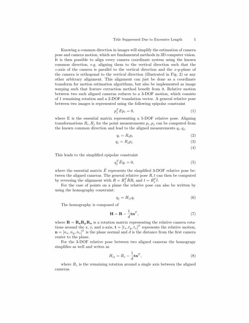
(a) (b)
Fig. 2. (a) 3D scene with two camera frames in general position. (b) Cameras after de-rotation such that both camera frames are aligned with the vertical direction (gravitydirection).
Title Suppressed Due to Excessive Length 5
Knowing a common direction in images will simplify the estimation of camerapose and camera motion, which are fundamental methods in 3D computer vision.It is then possible to align every camera coordinate system using the knowncommon direction, e.g. aligning them to the vertical direction such that thez-axis of the camera is parallel to the vertical direction and the x-y-plane ofthe camera is orthogonal to the vertical direction (illustrated in Fig. 2) or anyother arbitrary alignment. This alignment can just be done as a coordinatetransform for motion estimation algorithms, but also be implemented as imagewarping such that feature extraction method benefit from it. Relative motionbetween two such aligned cameras reduces to a 3-DOF motion, which consistsof 1 remaining rotation and a 2-DOF translation vector. A general relative posebetween two images is represented using the following epipolar constraint
pTj Epi = 0, (1)
where E is the essential matrix representing a 5-DOF relative pose. Aligningtransformations Ri, Rj for the point measurements pi, pj can be computed fromthe known common direction and lead to the aligned measurements qi, qj .
qi = Ripi (2)
qj = Rjpj (3)
(4)
This leads to the simplified epipolar constraint
qTj Eqi = 0, (5)
where the essential matrix E represents the simplified 3-DOF relative pose be-tween the aligned cameras. The general relative pose R, t can then be computedby reversing the alignment with R = RT
j RRi and t = RTj t.
For the case of points on a plane the relative pose can also be written byusing the homography constraint:
qj = Hijqi (6)
The homography is composed of
H = R−1
dtnT , (7)
where R = RzRyRx is a rotation matrix representing the relative camera rota-tions around the x, y, and z-axis, t = [tx, ty, tz]
T represents the relative motion,n = [nx, ny, nz]
T is the plane normal and d is the distance from the first cameracenter to the plane.
For the 3-DOF relative pose between two aligned cameras the homograpysimplifies as well and writes as
Hij = Rz −1
dtnT , (8)
where Rz is the remaining rotation around a single axis between the alignedcameras.

6 Authors Suppressed Due to Excessive Length
3.1 Previous approaches - 3pt relative pose using the epipolar
constraint
All the previous approaches that solve the 3pt+1 problem [10, 13, 14] have incommon that they utilize the epipolar constraint to set up the equations forrelative pose estimation.
qTj Eijqi = 0 (9)
where Eij is the essential matrix composed of Eij = [tij ]xRij .However, for this case, when only 3 point correspondences are necessary,
one can consider to use the homography constraint alternatively. 3 points bydefinition are always co-planar and form a plane. For any such 3 points thehomography constraint will hold. It is therefore possible to use the homographyconstraint instead of the epipolar constraint to solve the 3pt+1 problem. In thenext section we show the derivation of the solution to this novel idea.
3.2 3pt relative pose using the homography constraint
The general homography relation for points belonging to a 3D plane and pro-jected in two different views is defined as follows :
qj = Hijqi (10)
with qi =⇥
xi yi wi
⇤Tand qj =
⇥
xj yj wj
⇤Tthe projective coordinates of the
points between the views i and j. Hij is given by :
Hij = Rij −1
dtnT (11)
where Rij and t are respectively the rotation and the translation between viewsi and j and where d is the distance between the camera i and the 3D planedescribed by the normal n.In our case, we assume that the camera intrinsic parameters are known andthat the points qi and qj are normalized. We also consider that the attitudeof the cameras for both views are known and that these attitude measurementshave been used to align the camera coordinate system with the vertical (gravity)direction. In this way, only the yaw angle θ between the views remains unknown.
H = Rz −1
d[tx, ty, tz]
T [nx, ny, nz] (12)
Without loss of generality Eq. 12 can be written as
H = Rz − d[tx, ty, 1]T [nx, ny, nz]. (13)
In Eq. 13 the scale of the parameter tz has been included in d and thusthe z-component of the translation can be set to 1. This reformulation of the
Title Suppressed Due to Excessive Length 7
parameters proves useful for the used Groebner basis technique for solving theequation system. For the case of very small z-motions this choice could lead tonumerical instability but in such cases any other motion direction could be setto 1 instead. However, in practice we did not notice such an instability.
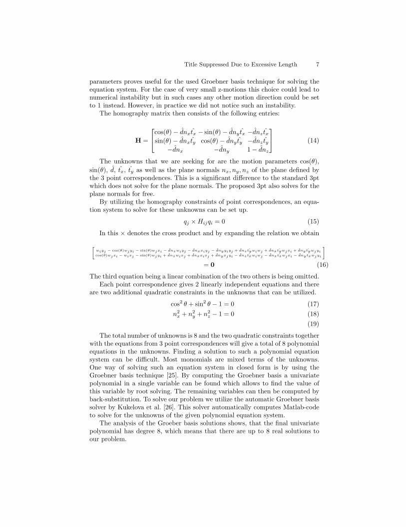
The homography matrix then consists of the following entries:
H =
2
4
cos(θ)− dnxtx − sin(θ)− dny tx −dnz txsin(θ)− dnxty cos(θ)− dny ty −dnz ty
−dnx −dny 1− dnz
3
5 (14)
The unknowns that we are seeking for are the motion parameters cos(θ),
sin(θ), d, tx, ty as well as the plane normals nx, ny, nz of the plane defined bythe 3 point correspondences. This is a significant difference to the standard 3ptwhich does not solve for the plane normals. The proposed 3pt also solves for theplane normals for free.
By utilizing the homography constraints of point correspondences, an equa-tion system to solve for these unknowns can be set up.
qj ⇥Hijqi = 0 (15)
In this ⇥ denotes the cross product and by expanding the relation we obtain
h
wiyj − cos(θ)wjyi − sin(θ)wjxi − dnzwiyj − dnxxiyj − dnyyiyj + dnztywiwj + dnxtywjxi + dnytywjyi
cos(θ)wjxi − wixj − sin(θ)wjyi + dnzwixj + dnxxixj + dnyxjyi − dnztxwiwj − dnxtxwjxi − dnytxwjyi
i
= 0 (16)
The third equation being a linear combination of the two others is being omitted.Each point correspondence gives 2 linearly independent equations and there
are two additional quadratic constraints in the unknowns that can be utilized.
cos2 θ + sin2 θ − 1 = 0 (17)
n2x + n2
y + n2z − 1 = 0 (18)
(19)
The total number of unknowns is 8 and the two quadratic constraints togetherwith the equations from 3 point correspondences will give a total of 8 polynomialequations in the unknowns. Finding a solution to such a polynomial equationsystem can be difficult. Most monomials are mixed terms of the unknowns.One way of solving such an equation system in closed form is by using theGroebner basis technique [25]. By computing the Groebner basis a univariatepolynomial in a single variable can be found which allows to find the value ofthis variable by root solving. The remaining variables can then be computed byback-substitution. To solve our problem we utilize the automatic Groebner basissolver by Kukelova et al. [26]. This solver automatically computes Matlab-codeto solve for the unknowns of the given polynomial equation system.
The analysis of the Groeber basis solutions shows, that the final univariatepolynomial has degree 8, which means that there are up to 8 real solutions toour problem.
8 Authors Suppressed Due to Excessive Length
3.3 Degenerate conditions
In this section we discuss the degenerate conditions for the proposed 3pt ho-mography method. The degenerate conditions for the standard 3pt method havebeen discussed in detail in [13, 14, 10]. In these papers it is pointed out that acollinear configuration of 3D points is in general not a degenerate condition forthe 3pt method, while it is one for the 5pt method. Degenerate conditions forthe standard 3pt algorithm however are collinear points that are parallel to thetranslation direction and points that are coplanar to the translation vector. Weinvestigated if these scenarios also pose degenerate conditions for the proposed3pt homography method by conducting experiments with synthetic data. De-generate cases could be identified by a rank loss of the action matrix within theGroebner basis solver. These tests showed that the proposed method shares thedegenerate conditions of the standard 3pt method but in addition also has adegenerate condition for the case of collinear points. This is understandable asthe 3pt homography method also solves for the plane normal which then has anundefined degree of freedom around the axis of the collinear points. The resultsof the comparison are summarized in Table 1.
Table 1. Comparison of the degenerate conditions for the standard 3pt method andthe proposed 3pt homography method.
3pt 3pt-homography
collinear points no yescollinear points parallel to translation direction yes yespoints coplanar to translation vector yes yes
4 Experiments
The proposed method is evaluated on both synthetic and real datasets.
4.1 Synthetic evaluation
The synthetic evaluation is conducted under the following setup. Focal length ofthe camera is 1000 pixel with a field of view of 45 degrees. The first camera isset to the origin of the coordinate frame and kept fixed. The base-line betweenthe first and second camera is set to 0.2 i.e., 20% of the average scene depth.The scene consists of 200 randomly sampled points. The algorithm is evaluatedunder varying image noise and increasing IMU noise (roll and pitch) on twoconfigurations, sideways and forward motion of the camera. Each configuration isevaluated on 100 randomly sampled cameras. For the evaluation of the syntheticdata we use the following error measure:

Title Suppressed Due to Excessive Length 9
– Angle difference in R: ξR = cos−1((Tr(RR>)− 1)/2)
– Direction difference in t: ξt = cos−1((t>t)/(ktkktk))
Where R, t denote the ground-truth transformation and R, t are the corre-sponding estimated transformations.
Fig. 3 and Fig. 4 compare the 3-point homography based algorithm to thegeneral 5-point [2] and the 3-point algorithms [13]. The evaluation shows thatthe proposed method outperforms the 5pt algorithm, in terms of accuracy. Underperfect IMU measurements the algorithm is robust to image noise and performssignificantly better than the 5pt algorithm and equally good as the 3pt algorithm.With increasing IMU noise the performance of the 3pt and 3pt-homography(proposed) algorithm are still comparable to the 5pt algorithm.
Sidewaysmotion
0 0.1 0.2 0.3 0.4 0.5 0.6 0.7 0.8 0.9 10
0.05
0.1
0.15
0.2
0.25
0.3
0.35
Noise in Pixel
Ro
tatio
n E
rro
r in
De
gre
e
Quantile
5pt3pt3pt−homography
0 0.1 0.2 0.3 0.4 0.5 0.6 0.7 0.8 0.9 10
0.2
0.4
0.6
0.8
1
1.2
1.4
Noise in Pixel
Tra
nsla
tio
n E
rro
r in
De
gre
e Quantile
5pt3pt3pt−homography
Forw
ard
motion
0 0.1 0.2 0.3 0.4 0.5 0.6 0.7 0.8 0.9 10
0.05
0.1
0.15
0.2
0.25
0.3
0.35
Noise in Pixel
Ro
tatio
n E
rro
r in
De
gre
e
Quantile
5pt3pt3pt−homography
0 0.1 0.2 0.3 0.4 0.5 0.6 0.7 0.8 0.9 10
0.2
0.4
0.6
0.8
1
1.2
1.4
1.6
1.8
Noise in Pixel
Tra
nsla
tio
n E
rro
r in
De
gre
e Quantile
5pt3pt3pt−homography
Fig. 3. Evaluation of the 3 point algorithm under varying image noise for two differentmotion settings (sideways and forward motion)
Sidewaysmotion
0 0.1 0.2 0.3 0.4 0.5 0.6 0.7 0.8 0.9 10
0.05
0.1
0.15
0.2
0.25
0.3
0.35
0.4
Rotation Noise in Degree (Pitch)
Ro
tatio
n E
rro
r in
De
gre
e
Quantile
5pt3pt3pt−homography
0 0.1 0.2 0.3 0.4 0.5 0.6 0.7 0.8 0.9 10.1
0.2
0.3
0.4
0.5
0.6
0.7
0.8
Rotation Noise in Degree (Pitch)
Tra
nsla
tio
n E
rro
r in
De
gre
e Quantile
5pt3pt3pt−homography
0 0.1 0.2 0.3 0.4 0.5 0.6 0.7 0.8 0.9 10
0.05
0.1
0.15
0.2
0.25
0.3
0.35
0.4
Rotation Noise in Degree (Roll)
Ro
tatio
n E
rro
r in
De
gre
e
Quantile
5pt3pt3pt−homography
0 0.1 0.2 0.3 0.4 0.5 0.6 0.7 0.8 0.9 10
0.5
1
1.5
2
2.5
Rotation Noise in Degree (Roll)
Tra
nsla
tio
n E
rro
r in
De
gre
e Quantile
5pt3pt3pt−homography
Forw
ard
motion
0 0.1 0.2 0.3 0.4 0.5 0.6 0.7 0.8 0.9 10
0.05
0.1
0.15
0.2
0.25
0.3
0.35
Rotation Noise in Degree (Pitch)
Ro
tatio
n E
rro
r in
De
gre
e
Quantile
5pt3pt3pt−homography
0 0.1 0.2 0.3 0.4 0.5 0.6 0.7 0.8 0.9 10
0.2
0.4
0.6
0.8
1
1.2
1.4
1.6
1.8
Rotation Noise in Degree (Pitch)
Tra
nsla
tio
n E
rro
r in
De
gre
e Quantile
5pt3pt3pt−homography
0 0.1 0.2 0.3 0.4 0.5 0.6 0.7 0.8 0.9 10
0.05
0.1
0.15
0.2
0.25
0.3
0.35
0.4
Rotation Noise in Degree (Roll)
Ro
tatio
n E
rro
r in
De
gre
e
Quantile
5pt3pt3pt−homography
0 0.1 0.2 0.3 0.4 0.5 0.6 0.7 0.8 0.9 10
0.2
0.4
0.6
0.8
1
1.2
1.4
1.6
1.8
2
Rotation Noise in Degree (Roll)
Tra
nsla
tio
n E
rro
r in
De
gre
e Quantile
5pt3pt3pt−homography
Fig. 4. Evaluation of the 3-point algorithm under different IMU noise and constantimage noise of 0.5 pixel standard deviation. First row: sideways motion of the camerawith varying pitch angle (left) and varying roll angle (right). Second row: forwardmotion of the camera with varying pitch angle (left) and varying roll angle (right).

10 Authors Suppressed Due to Excessive Length
4.2 Experiments on real data with Vicon ground-truth
In order to have a practical evaluation of our algorithm, several real datasets havebeen collected with reliable ground-truth data. The ground-truth data has beenobtained by conducting experiments in a room equipped with a Vicon motioncapture system made of 22 cameras. Synchronization between visual and ground-truth data has been obtained by a pre-processing step. We used the VICON dataas inertial measures and scale factor in the different experiments. The sequenceshave been acquired with a perspective camera mounted on a mobile robot andon an handheld system in order to have planar and general trajectories. Thelengths of these trajectories are between 20 and 50 meters and the number ofimages are between 200 and 350 per sequence. We propose a comparison withthe five-point algorithm and the general three-point algorithm (implementedafter [13] in order to prove the efficiency of the proposed method. Both methodsuse the same matched feature point sets as input and apply RANSAC algorithmin order to select the inliers. For the case of the 5pt algorithm and the standard3pt algorithm a least squares estimation is performed on the inlier sets for theestimation of the motion parameters, while for the proposed 3pt method thiswas not possible.
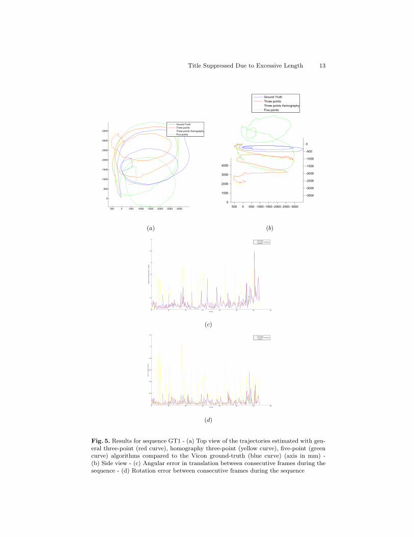
Figure 5 shows the results for the GT1 sequence. For this sequence the camerahas been mounted on a mobile robot in forward direction the z-axis of the cameraparallel to the ground plane. The robot was mainly moving forward which posesa difficult situation for a visual odometry system. We can note that all thealgorithms show trajectories with a strong drift in z direction (height) even if theglobal shapes of the trajectories are quite similar. The mean angular error of thetranslation and the mean error of the rotation of consecutive frames during thesequence are respectively equal to 0.2399 and 0.0052 for the general three-point,0.2455 and 0.0048 for the three-point homography and 0.4302 and 0.0112 for thefive-point methods. The details of these errors during the complete sequence aregiven in Figures 5 (c) and (d). The three-point homography method presentsthe best results and also the minimum drift at the end of the motion. Such driftas visible in the plots is typical for visual odometry systems without structuretriangulation and local optimization. It is however noticeable that the purelyvision based 5pt algorithm has much more difficulties with this sequence thanthe 3pt methods that use an additional common direction.
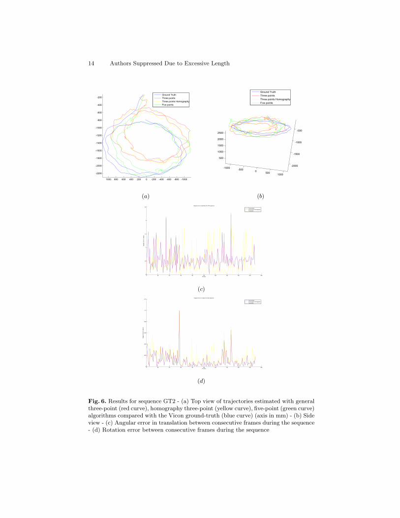
Figure 6 shows the results for the GT2 sequence. In this sequence the camerahas been handheld, pointing toward the ground in a 45 degree angle and wasmoved sideways in a circular trajectory. This comprised a less difficult settingthan for GT1. In this case, the five-point algorithm presents globally betterresults but the three-point homography algorithm is better than the generalthree-point approach. As previously, the details of the rotation and translationerrors between consecutive images are given in Figures 6 (c) and (d). We cannote that the rotation error of the three-point homography is smaller than thetwo other approaches.
Title Suppressed Due to Excessive Length 11
5 Conclusion
In this paper we presented a new formulation for the 3pt plus common direc-tion relative pose problem using a homography formulation. We show that itis possible to utilize the homography constraint for an alternative formulationfor the 3pt problem. With the same number of input point correspondences thehomography formulation also solves for the plane normal in addition to the mo-tion parameters. In experiments with synthetic data and real image sequenceswe show that the alternative formulation produces similar results to the stan-dard 3pt and also demonstrate that additional information in kind of a commondirection allows to get better visual odometry results in certain configurations.
Acknowledgement. This work has been partially supported by Projet ANRBlanc International DrAACaR-ANR-11-IS03-0003 and a Google Award.
References
1. Hartley, R., Zisserman, A.: Multiple View Geometry in Computer Vision. Secondedn. Cambridge University Press, ISBN: 0521540518 (2004)
2. Nister, D.: An efficient solution to the five-point relative pose problem. IEEETrans. Pattern Anal. Mach. Intell. 26 (2004) 756–777
3. Scaramuzza, D.: 1-point-ransac structure from motion for vehicle-mounted camerasby exploiting non-holonomic constraints. International Journal of Computer Vision95 (2011) 74–85
4. Kneip, L., Martinelli, A., Weiss, S., Scaramuzza, D., Siegwart, R.: Closed-form solu-tion for absolute scale velocity determination combining inertial measurements anda single feature correspondence. In: IEEE International Conference on Roboticsand Automation, ICRA 2011, Shanghai, China, 9-13 May 2011. (2011) 4546–4553
5. Vieville, T., Clergue, E., Facao, P.D.S.: Computation of ego-motion and structurefrom visual and inertial sensors using the vertical cue. In: Computer Vision, 1993.Proceedings., Fourth International Conference on, IEEE (1993) 591–598
6. Corke, P.: An inertial and visual sensing system for a small autonomous helicopter.Journal of Robotic Systems 21 (2004) 43–51
7. Lobo, J., Dias, J.: Vision and inertial sensor cooperation using gravity as a verticalreference. IEEE Trans. Pattern Anal. Mach. Intell. 25 (2003) 1597–1608
8. Weiss, S., Siegwart, R.: Real-time metric state estimation for modular vision-inertial systems. In: Robotics and Automation (ICRA), 2011 IEEE InternationalConference on, IEEE (2011) 4531–4537
9. Domke, J., Aloimonos, Y.: Integration of visual and inertial information for ego-motion: a stochastic approach. In: Robotics and Automation, 2006. ICRA 2006.Proceedings 2006 IEEE International Conference on, IEEE (2006) 2053–2059
10. Kalantari, M., Hashemi, A., Jung, F., Guedon, J.P.: A new solution to the relativeorientation problem using only 3 points and the vertical direction. Journal ofMathematical Imaging and Vision 39 (2011) 259–268
11. Antone, M.E., Teller, S.J.: Automatic recovery of relative camera rotations forurban scenes. In: CVPR, IEEE Computer Society (2000) 2282–2289
12. Oreifej, O., da Vitoria Lobo, N., Shah, M.: Horizon constraint for unambiguousuav navigation in planar scenes. In: IEEE International Conference on Roboticsand Automation, ICRA 2011, Shanghai, China, 9-13 May 2011. (2011) 1159–1165
12 Authors Suppressed Due to Excessive Length
13. Fraundorfer, F., Tanskanen, P., Pollefeys, M.: A minimal case solution to thecalibrated relative pose problem for the case of two known orientation angles. InDaniilidis, K., Maragos, P., Paragios, N., eds.: ECCV (4). Volume 6314 of LectureNotes in Computer Science., Springer (2010) 269–282
14. Naroditsky, O., Zhou, X.S., Gallier, J.H., Roumeliotis, S.I., Daniilidis, K.: Twoefficient solutions for visual odometry using directional correspondence. IEEETrans. Pattern Anal. Mach. Intell. 34 (2012) 818–824
15. Chum, O., Werner, T., Matas, J.: Two-view geometry estimation unaffected by adominant plane. In: CVPR (1), IEEE Computer Society (2005) 772–779
16. Szeliski, R., Torr, P.H.S.: Geometrically constrained structure from motion: Pointson planes. In Koch, R., Gool, L.J.V., eds.: SMILE. Volume 1506 of Lecture Notesin Computer Science., Springer (1998) 171–186
17. Olivier Saurer, F.F., Pollefeys, M.: Homography based visual odometry with knownvertical direction and weak manhattan world assumption. In: IEEE/IROS Work-shop on Visual Control of Mobile Robots (ViCoMoR 2012). (2012)
18. Ortin, D., Montiel, J.: Indoor robot motion based on monocular images. Robotica19 (2001) 331–342
19. Troiani, C., Martinelli, A., Laugier, C., Scaramuzza, D.: 1-point-based monocularmotion estimation for computationally-limited micro aerial vehicles. In: MobileRobots (ECMR), 2013 European Conference on, IEEE (2013) 13–18
20. Bazin, J.C., Demonceaux, C., Vasseur, P., Kweon, I.: Rotation estimation andvanishing point extraction by omnidirectional vision in urban environment. TheInternational Journal of Robotics Research 31 (2012) 63–81
21. Li, B., Heng, L., Lee, G.H., Pollefeys, M.: A 4-point algorithm for relative poseestimation of a calibrated camera with a known relative rotation angle. In: Proc.IEEE/RSJ Int. Conf. on Intelligent Robots and Systems, IROS 2013, Tokyo, Japan.(2013)
22. Troiani, C., Martinelli, A., Laugier, C., Scaramuzza, D.: 2-point-based outlierrejection for camera-imu systems with applications to micro aerial vehicles. In:IEEE International Conference on Robotics and Automation (ICRA), Hong Kong,2014. (2014)
23. Martinelli, A.: Closed-form solution of visual-inertial structure from motion. In-ternational Journal of Computer Vision 106 (2014) 138–152
24. Lee, G.H., Fraundorfer, F., Pollefeys, M.: Mav visual slam with plane constraint.In: ICRA, IEEE (2011) 3139–3144
25. Cox, D.A., Little, J., O’Shea, D.: Ideals, Varieties, and Algorithms: An Introduc-tion to Computational Algebraic Geometry and Commutative Algebra, 3/e (Un-dergraduate Texts in Mathematics). Springer-Verlag New York, Inc., Secaucus,NJ, USA (2007)
26. Kukelova, Z., Bujnak, M., Pajdla, T.: Automatic generator of minimal problemsolvers. (In: ECCV (3)) 302–315
Title Suppressed Due to Excessive Length 13
(a) (b)
0 50 100 150 200 250 300 3500
0.5
1
1.5
2
2.5
3
# Frame
An
gu
lar
err
or
of
the
tra
nsla
tio
n in
ra
dia
ns
Three points
Three points Homography
Five points
(c)
0 50 100 150 200 250 300 3500
0.02
0.04
0.06
0.08
0.1
0.12
# Frame
Err
or
in r
ota
tio
n in
ra
dia
ns
Three points
Three points Homography
Five points
(d)
Fig. 5. Results for sequence GT1 - (a) Top view of the trajectories estimated with gen-eral three-point (red curve), homography three-point (yellow curve), five-point (greencurve) algorithms compared to the Vicon ground-truth (blue curve) (axis in mm) -(b) Side view - (c) Angular error in translation between consecutive frames during thesequence - (d) Rotation error between consecutive frames during the sequence
14 Authors Suppressed Due to Excessive Length
(a) (b)
0 20 40 60 80 100 120 140 160 180 2000
0.5
1
1.5
2
2.5
#Frame
An
gu
lar
err
or
in r
ad
ian
s
Angular error in translation for GT2 sequence
Three points
Three points Homography
Five points
(c)
0 20 40 60 80 100 120 140 160 180 2000
0.02
0.04
0.06
0.08
0.1
0.12
# Frame
Angula
r err
os in r
adia
ns
Angular errors in rotation for GT2 sequence
Three points
Three points Homography
Five points
(d)
Fig. 6. Results for sequence GT2 - (a) Top view of trajectories estimated with generalthree-point (red curve), homography three-point (yellow curve), five-point (green curve)algorithms compared with the Vicon ground-truth (blue curve) (axis in mm) - (b) Sideview - (c) Angular error in translation between consecutive frames during the sequence- (d) Rotation error between consecutive frames during the sequence