A Hardware Implementation for Component Failure Handling...
100
A Hardware Implementation for Component Failure Handling in Isotach Token Managers A Thesis in TCC 402 Presented to the Faculty of the School of Engineering and Applied Science University of Virginia In Partial Fulfillment of the Requirements for the Degree Bachelor of Science in Electrical Engineering Submitted by Christopher F. Batten March 26, 1999 On my honor as a University student, on this assignment I have neither given nor received unauthorized aid as defined by the Honor Guidelines for Papers in TCC Courses. Signed ___________________________ Approved: _____________________________________ Date: __________ Ronald Williams (Technical Advisor) Approved: _____________________________________ Date: __________ Kathryn Neeley (TCC Advisor)
-
Upload
nguyentruc -
Category
Documents
-
view
219 -
download
0
Transcript of A Hardware Implementation for Component Failure Handling...

A Hardware Implementation for Component Failure Handling
in Isotach Token Managers
A Thesis in TCC 402
Presented to the Faculty of the
School of Engineering and Applied Science
University of Virginia
In Partial Fulfillment
of the Requirements for the Degree
Bachelor of Science in Electrical Engineering
Submitted by
Christopher F. Batten
March 26, 1999
On my honor as a University student, on this assignment I have neither given nor received unauthorized aid as defined by the Honor Guidelines for Papers in TCC Courses.
Signed ___________________________
Approved: _____________________________________ Date: __________
Ronald Williams (Technical Advisor)
Approved: _____________________________________ Date: __________
Kathryn Neeley (TCC Advisor)

i
Table of Contents Acknowledgements ....................................................................................................................................iii Abstract ...................................................................................................................................................... iv Glossary ....................................................................................................................................................... v List of Figures ............................................................................................................................................ ix
Chapter One: Introduction........................................................................................................................ 1 1.1 Distributed Systems ........................................................................................................................... 1 1.2 Logical Time ...................................................................................................................................... 2 1.3 Isotach Networks................................................................................................................................ 4
1.3.1 Current Isotach Prototypes .......................................................................................................... 5 1.3.2 Isotach Fault Tolerance ............................................................................................................... 7
1.4 Design Modifications for Failed Neighbor Handling ........................................................................ 8
Chapter Two: Literature Review............................................................................................................ 10 2.1 Addressing Causality in Distributed Systems.................................................................................. 10 2.2 Fault Tolerant Distributed Systems.................................................................................................. 12
Chapter Three: Detecting and Handling Failed Neighbors.................................................................. 14 3.1 Detecting Failed Neighbors.............................................................................................................. 14
3.1.1 Additional Background: How Network Configuration Parameters are Stored ......................... 14 3.1.2 Additional Background: Current Timer Hardware.................................................................... 15 3.1.3 Hardware To Detect Permanent Failures .................................................................................. 16
3.2 Handling Failed Neighbors .............................................................................................................. 17 3.2.1 Additional Background: How TMs Store Neighbor Information ............................................. 18 3.2.2 Buffering the Valid Bits ............................................................................................................ 19 3.2.3 Failure State Machine................................................................................................................ 21 3.2.4 Modifying the Port State Machines........................................................................................... 21
Chapter Four: Notifying Hosts of a Failed Neighbor............................................................................ 22 4.1 Additional Background: Isotach Signals.......................................................................................... 22 4.2 Design Alternatives.......................................................................................................................... 23 4.3 Modifications to the Signal Logic.................................................................................................... 24 4.4 Modifications to the Failure State Machine..................................................................................... 26
Chapter Five: Token Manager Ping ....................................................................................................... 27 5.1 Additional Background: Myrinet Routing Flits ............................................................................... 27 5.2 General Ping Concept ...................................................................................................................... 28 5.3 Structure of a Ping Message............................................................................................................. 28 5.4 Two Methods for Handling Return Route Information ................................................................... 29 5.5 Modifications to the Input State Machine and the Return Route Buffers ....................................... 31

ii
5.6 The Ping Handler State Machine ..................................................................................................... 33 5.7 Modifications to the Master State Machine and at the Output FIFO Bus ....................................... 34
Chapter Six: Results - Schematics, Simulation, and Synthesis ............................................................ 35 6.1 The Token Manager Schematics...................................................................................................... 35 6.2 Functional Simulation ...................................................................................................................... 38 6.3 Token Manager Synthesis ................................................................................................................ 45
Chapter Seven: The Logical Dead Space Problem................................................................................ 47 7.1 What is Dead Space?........................................................................................................................ 47 7.2 Solutions to the Dead Space Problem.............................................................................................. 48 7.3 How All Three Modifications Address the Dead Space Problem ................................................... 49
Chapter Eight: Conclusions..................................................................................................................... 51 8.1 Project Summary.............................................................................................................................. 51 8.2 Reflections and Interpretation.......................................................................................................... 52 8.3 Recommendations ............................................................................................................................ 53
References.................................................................................................................................................. 54
Appendix A: Detailed Description of Original Token Manager Design
Appendix B: VHDL and Simulation Script Files

iii
Acknowledgements I would like to express my deepest gratitude to the many individuals who made this undergraduate thesis possible. I would like to thank my TCC advisor, Professor Kathryn Neeley, for her advice and support in composing the final technical report. I would also like to thank my TCC advisor from this past fall, Professor Bryan Pfaffenberger, for his help in creating the thesis framework and his valuable techniques for effective technical presentations.
This thesis would not be possible without the assistance of the isotach research group. The members of the research group have always been willing to answer my many questions and to give me useful advice. I would like to especially thank my technical advisor, Professor Ronald Williams, of the electrical engineering department here at the University of Virginia. Professor Williams has allowed me the freedom to develop this project on my own, yet has always been available to help me keep the project feasible and worthwhile. In addition to his technical support, Professor Williams has given me much needed advice on some of the largest decisions I have had to make about my future.
Professor Paul Reynolds and Dr. Craig Williams of the computer science department have been invaluable mentors throughout the past year and a half. Both Professor Reynolds and Dr. Williams have sacrificed a great deal of time on my behalf, and for their strong support, I am sincerely thankful. I would like to thank Professor Williams, Professor Reynolds, and Dr. Williams for allowing me to experience true research first hand from the theoretical to the practical and from proposals to testing. My experiences with the isotach research group have inspired me to continue my studies on the graduate level.
Many other individuals have helped me with my undergraduate thesis. I would like to thank Dr. Maximo Salinas who has helped me through several obstacles. Brian Kuebert was responsible for designing and implementing the original token manager hardware, and I thank him for allowing me to peer over his shoulder and ask way too many questions. Arin Sime has helped me greatly this semester as I learned new tools and tried to understand how to turn VHDL into a final product.
I would like to also thank my parents for their eternal support no matter what I am pursuing. Finally, I would like to thank Professor Stephen Wilson of the electrical engineering department for advising me the past four years. Ever since my very first college design project, Professor Wilson has always had the time to help me make both the large and small decisions in life.

iv
Abstract Isotach networks are a unique class of networks currently being developed at the University of Virginia under the guidance of Professor Paul Reynolds and Dr. Craig Williams of the computer science department. These networks make powerful guarantees concerning the timing of messages sent between distinct processors, and have the potential to significantly impact distributed processing. The isotach research group has already constructed a software prototype, which is being used for performance analysis and as a platform for further development. In order to reduce the overhead involved in using an isotach network, the major isotach components have also been implemented in hardware under the guidance of Professor Ronald Williams. The preliminary prototypes included only limited fault tolerance capabilities, and specifically lacked the ability to handle failed isotach devices. Therefore, my undergraduate thesis project was to design and implement three modifications necessary for the token manager, an isotach device, to detect and handle failed neighbors. Isotach networks are based on a system of logical time. Logical time is a method for decentralizing a global clock, and it allows processes in an isotach network to predict when a message will logically reach a destination. The isotach prototypes implement logical time through two isotach specific components: token managers (TMs) and switch interface units (SIUs). Each token manager is located at a network switch and is responsible for advancing logical time. Each SIU is located in between the network and a host and is responsible for buffering messages and delivering them to the host at the appropriate logical time.
In the original prototypes, a TM or SIU failure caused a fatal halt in logical time. I addressed this failure mode through three TM hardware modifications. The first modification involved adding the necessary timeout logic for a TM to detect when a neighbor has permanently failed and to allow the TM to sever the failed neighbor from the isotach network. The second modification enables the TM to send a one-bit error signal to all hosts. Special consideration was paid to the timely delivery and reset of this error signal. This signal bit notification is insufficient for a host to determine exactly which TM has failed, and thus the third modification allows a host to send a special message to a TM asking the TM if it is still operational. By sending these messages to all of the TMs, a host can determine which specific TM has failed. All three modifications were successfully implemented and functionally simulated. The logical dead space problem is an important anomaly found in systems that attempt to handle failed TMs by logically severing them from the network. The problem arises because tokens and isotach messages propagate through the network differently, and consequently isotach messages can freely pass through logically dead areas of the network while tokens cannot. The logical dead space problem can allow isotach messages to violate the fundamental isotach synchronization guarantees. This problem was one of the primary reasons the isotach architects did not address failed network components in the original prototypes. All three of the modifications can work together to adequately address the logical dead space problem by giving hosts the information necessary to determine which isotach messages are valid and which have passed through dead space. The project has directly impacted the isotach research group by contributing to the group’s year long focus on fault tolerance. More specifically, I have outlined a specific implementation for detecting and handling failed neighbors, and I have also clarified and addressed the logical dead space problem. Even if the design is not actually used, the project has still impacted the group by encouraging discussion on fault tolerance issues. Fault tolerance is a major concern when examining isotach networks for use in critical applications. My undergraduate thesis project has contributed to the fundamental goal of creating robust and useful isotach networks.

v
Glossary asynchronous Tasks are executed independently, and thus the temporal relationship
between tasks is not predictable. Asynchronous systems lack shared signals such as clocks and semaphores.
atomicity Property where tasks appear to be executed as an indivisible unit and are not interrupted by other tasks.
barrier Isotach synchronization mechanism that allows one host to wait until a specific number of hosts reach the same barrier in their execution.
centralized locks Method for concurrency control in a distributed environment. A single machine, known as the centralized lock manager, is responsible for causal guarantees and therefore hosts must talk to the centralized lock manager before sending a message.
comparator Logic component that takes two bit strings as input and outputs a one if they are identical and otherwise outputs a zero.
counter Logic component that outputs a binary number that is incremented by one on every rising edge of the clock input.
dead space Area of the network where isotach logical time is no longer valid and thus assumptions concerning isochronicity and sequential consistency can no longer be made. The inverse of the LVR.
deadlock Situation where multiple processing units cannot continue since each is waiting for the other to do something.
distributed system Collection of independent (usually heterogeneous) machines that work together for some common goal.
epoch Higher order unit of isotach logical time that must be greater than the diameter of the network. At each epoch boundary, TMs clear their signal registers and SIUs deliver all signals to their respective hosts.
failure state machine (FSM)
TM state machine that controls the failure counter, valid bits, and issuing the error notification. Part of the first and second modifications.
failure threshold Multiple of the scale that is related to detecting failed neighbors. It is one more than the number of reminder waves to send before declaring a neighbor dead.
fault tolerance Ability of a system to continue operating (possibly in a reduced capacity) after a software or hardware failure.
field programmable gate array (FPGA)
Chip that allows logic to be programmed into it after fabrication. Usually made up of an array of logic modules. Both the logic modules themselves and the interconnect between modules are programmable.

vi
first in first out (FIFO) Buffer where items are taken out in the same order they arrived.
flit Eight bit Myrinet routing entity that tells a switch how the attached message should be routed through the switch. Each switch strips away one routing flit.
galileo Software tool that synthesizes hardware logic gates from VHDL for a specific family of FPGAs.
host Machine in a distributed system responsible for performing application level tasks. The fundamental processing entity.
input valid state machine (IVSM)
TM state machine that monitors incoming words from the input FIFO and determines if they are a valid part of a token or a host-to-TM ping.
isochronicity Property where a task appears to be executed on multiple machines at the same time.
isotach message One of two forms of isotach communication. Carries application level data with a timestamp indicating when the message should be delivered to the target host.
isotach networks Unique type of distributed system that can make low cost and highly scalable synchronization guarantees including isochronicity and sequential consistency.
Linux Open source operating system for x86 Intel platforms.
lock Mechanism for concurrency control. When a process needs to perform a mutually exclusive task it sets the lock and then when it is finished it releases the lock.
logic modules Basic programmable unit of an FGPA that can implement several hardware gates. Synthesis tools translate VHDL into logic modules.
logical time Method for ordering events in a distributed system that depends on relative time instead of physical time.
logically valid region (LVR)
Area of the network where synchronization guarantees are valid.
mapsh Tool used to map hardware logic on the gate level into programmable function units for the ORCA FPGAs.
master state machine (MSM)
TM state machine that manages most of the higher level TM functions including sending token waves and reminder waves.
Mentor Graphics Collection of tools that allow a developer to write, compile, and organize VHDL.
multiplexor Logic component that allows a signal to choose which of several inputs should be directed to the output.

vii
Myrinet Commercial high speed network developed by Myricom, Inc. which can handle speeds up to 160 MHz.
network partitioning Network state where the network is divided into several parts. The network can be physically partitioned if a network link fails or may be logically partitioned if a TM fails.
parallel computer Computer with multiple (usually homogenous) processors that allow multiple tasks to execute concurrently. These processors are usually in close physical proximity to each other.
parsh Tool used to place PFUs into the ORCA FPGA framework and to route the wires that connect the PFUs.
ping Form of network communication that verifies a network component’s status. A ping is sent to the target and then is returned to the sender.
ping handler state machine (PHSM)
TM state machine that is responsible for moving the return route information from the return route buffers to the output FIFO bus.
ping verifier Combinational logic that sets ping_valid to one if the first two bytes of an incoming word match the isotach message type identifier (x0600)
port state machine (PSM) TM state machine that monitors one of the ports on the adjacent switch. It stores whether or not that port has received an appropriate token.
printed circuit board (PCB)
Board that holds hardware components and provides a medium for connecting those components.
programmable function unit (PFU)
Basic logic module for the ORCA family of FPGAs. Each PFU includes four flip-flops and four 16-bit lookup tables.
programmable read only memory (PROM)
Memory chip that can be programmed by a computer. A user provides an address as input and then the chip will produce the programmed data value at that memory location.
reminder waves Special token wave that duplicates previously issued token waves in an effort to elicit a response from a neighbor after a token has been lost.
return route buffers A 16 bit buffer and a 35 bit buffer that store the return route information until it can be placed on the output FIFO bus.
scalability Property of how a network handles adding more components to the network.
scale TM configuration parameter that indicates how long to wait before sending a reminder wave. The units are a multiple of the clock speed of the TM.

viii
sequential consistency Property where tasks on multiple hosts appear to be executed in a specific order.
signal Isotach communication mechanism that allows a host to notify all other hosts of some predefined event. A signal is delivered to all hosts at the same logical time.
switch Network component that is responsible for connecting multiple hosts and other switches together.
switch interface unit (SIU) Isotach devices that reside in between hosts and the rest of the network. These devices buffer isotach messages and then deliver these messages to the host at the appropriate logical time.
synchronous Tasks are executed at the same rate in lock step. Temporal relationships in synchronous systems are predictable.
synthesis Process by which hardware logic gates are created from a VHDL structural or behavioral description. Galileo is an example of a synthesis tool.
token Lightweight communication mechanism that marks the boundary between logical time pulses. Tokens are issued in waves and are propagated through the network by TMs.
token manager (TM) Isotach devices that are located at each switch in the network. These devices are responsible for monitoring the flow of tokens through the network.
token wave Collection of tokens issued from a TM to all of that TM’s neighbors.
valid buffer Register on the main FPGA that is responsible for storing whether or not corresponding devices on the adjacent switch are isotach devices.
VHSIC hardware description language (VHDL)
Programming language that includes several constructs suitable for modeling hardware. Developed for the federal government’s Very High Speed Integrated Circuits program.

ix
List of Figures
1-1 Example Isotach Network ............................................................. 4 1-2 Permanent Failure in an Isotach Network ......................................... 7 3-1 Parameter Storage ......................................................................... 16 3-2 Original Timer Hardware ................................................................ 16 3-3 Timer Hardware with Modifications ............................................... 17 3-4 TM’s Handling of Isotach and Non-Isotach Devices ........................ 19 3-5 Port State Machine ........................................................................ 20 3-6 Failure State Machine .................................................................... 22 4-1 Schematic of Err_sig and Err_clr Combinational Logic ................... 26 4-2 Modified Failure State Machine ..................................................... 27 5-1 How Messages are Routed in Myrinet ........................................... 28 5-2 A Host-to-TM Ping Message ......................................................... 30 5-3 Modified Input Valid State Machine ................................................ 33 5-4 Ping Handler State Machine ........................................................... 34 5-5 Schematic of Muxes on the Output FIFO Bus .................................. 35 6-1 Original Token Manager Schematic ................................................. 37 6-2 Modified Token Manager Schematic ............................................... 38 6-3 Trace of Failure Detection and Handling .......................................... 40 6-4 Magnified Trace of Failure Detection and Handling .......................... 41 6-5 Trace Showing Err_sig is Not Cleared at Epoch Boundaries ............. 42 6-6 Trace of Host-to-TM Ping .............................................................. 44 6-7 Trace of Host-to-TM Ping with Waiting for Token Wave ................. 45 7-1 Dead Space ........................................................................................ 48

1
Chapter One
Introduction This report describes the design, implementation, and testing of three modifications made to the current isotach hardware prototype. Isotach networks are a novel class of networks being developed at the University of Virginia that provide low-cost message ordering guarantees [13]. The current isotach hardware prototype, however, lacks the ability to handle permanently failed network components [7, 15]. The three modifications allow the hardware to detect and resolve this failure mode as well as notify all hosts in the system of the failure. These modifications can work together to address the logical dead space problem, an anomaly that occurs in systems that attempt to logically sever isotach devices. This chapter provides the general background on distributed systems, logical time, isotach networks, and the current prototypes necessary to understand the modifications and their impact on the system as a whole.
1.1 DISTRIBUTED SYSTEMS
The need for performance, reliability, and capacity has made the isolated sequential computer
almost obsolete. The computing industry has turned to multiple machines or processes working
together in order to satisfy growing scientific and commercial computing needs. This type of
parallelism can be found in redundant control systems, distributed databases, large multi-processor
computers, and isotach networks. The concurrent nature of these distributed systems is their
greatest advantage as well as the source of significant complications. For example, data duplicated
on multiple machines must be kept consistent, and tasks may have to be executed at the same time or
in a specific order on multiple independent machines.
As an analogy, consider a single carpenter who is charged with building a house. The carpenter
has complete control over the construction and can work in a very sequential manner, but the
complexity and size of the house are limited. A larger house can be built if multiple carpenters work
together. Carpenters can work on independent tasks at the same time or jointly work on complex
tasks. The carpenters, however, must be coordinated in some way to prevent duplication of work or
wrongly ordered tasks. A mechanism is needed to assure that the walls are not put up before the
foundation and that the roof goes on at the correct time. Notice that the complication in using
multiple carpenters is the communication between and management of the various individuals.
2
Similarly, the complication in a distributed system is the communication between and management
of the various machines. In the construction analogy, these complications are handled with the use
of a single foreman who has control over the project as a whole. The problem with this traditional
method is that if the foreman becomes ill the project usually goes into disarray. Additionally, the
manager-worker paradigm is not scalable. In other words, as more and more carpenters join the
project the foreman becomes a bottleneck reducing the overall efficiency. Scalability is a measure
of how well a system performs as more carpenters or machines are added. The foreman concept is
analogous to the traditional method in distributed systems of using a centralized lock manager [5].
Each machine must talk to the lock manger before performing a task to prevent inappropriate
ordering. What is needed is a distributed mechanism for ordering and managing the various
carpenters and machines.
1.2 LOGICAL TIME
Isotach networks are a unique type of distributed system that provide a means to efficiently
manage the complications arising from concurrency. These networks provide a low cost and highly
scalable mechanism to correctly order and manage communication between distributed machines
[13]. In the construction analogy, a possible distributed solution would be to give each carpenter a
synchronized watch and a list of activities to perform at very specific times. If any specific
carpenter wanted to tell another carpenter to perform a task, he would also include the exact time to
begin the task. In this way, multiple carpenters could perform the same task at the same time or
perform different tasks in the correct sequential order. Unfortunately, machines in a distributed
system do not have any form of an absolute synchronized clock. The key concept, however, is not
that each machine be synchronized with physical time, but instead that each machine be
synchronized relative to the other machines. Isotach networks achieve this form of relative
synchronicity through an implementation of logical time.
Logical time is a mechanism by which a host can specify a relative time when a message is to be
delivered to another host. In this way, a host can guarantee that multiple hosts receive a message at
the same time or in a specific order. Before examining the specific isotach implementation of
logical time it is useful to further understand two key properties desired in a distributed system:
isochronicity and sequential consistency. Isochronicity means that tasks appear to be executed at
the same time in a distributed system. Isochronicity is similar to atomicity since tasks appear to be
executed as an indivisible unit and are not interrupted by other tasks [13]. Using the carpenter
analogy, an isochronous action might be several carpenters laying individual portions of a larger

3
concrete foundation. All carpenters need to lay their portion at the same time so there are no seams,
and thus it is undesirable for a carpenter to be interrupted for a coffee break while in the middle of
his task. Similarly, there are instances where it is desirable for several machines to update a
duplicated variable at the same logical time without interruption so that the value of the variable
remains globally consistent.
Sequential consistency implies that the overall order of operations is consistent with the order
desired by each individual machine [13]. With a single carpenter or machine, sequential consistency
is trivial. Yet with multiple workers the situation becomes much more complex. For example,
assume the worker A tells worker B to lay the foundation and then a few minutes later tells worker
C to put up the walls. Worker A has specified an implicit order: he desires the foundation to be laid
before the walls are put up for the house. Now assume worker B runs out to get supplies, while
worker C immediately proceeds to the site and begins putting up the walls. Even though worker A
issued the two tasks in a distinct order, the concurrent nature of distributed processing has allowed
these two tasks to be executed such that they violate sequential consistency.
Logical time provides a mechanism to efficiently guarantee isochronicity and sequential
consistency. Isotach networks are a specific subset of logical time systems, where the logical time
between two machines is related to the logical distance between two machines [16]. Logical
distance may be based on the number of switches or some other deterministic metric. This key
feature of isotach networks is known as the isotach invariant, and it allows hosts to accurately
specify when messages will be delivered to other hosts in the network.

4
1.3 ISOTACH NETWORKS
Isotach networks are implemented using two isotach-specific devices: token managers (TMs)
and switch interface units (SIUs) [15]. TMs are located at each switch in the network, and are
responsible for handling the flow of tokens through the network. SIUs are positioned as buffers in
between the hosts and the network. A sample isotach network is show in Figure 1-1. A token has a
logical time stamp and is simply a marker that delineates the logical time pulses. If a second is a
pulse of real time, then a token is a pulse of logical time. A TM sends out a token with timestamp i
to each isotach device attached to the adjacent switch. This is known as a token wave. The TM
waits until it has received a return token with timestamp i from each isotach device and then issues a
new token wave with timestamp i+1. SIUs also receive and issue tokens. Thus, in the example
network, TM A would issue a token wave to Host 1’s SIU, Host 2’s SIU, and to TM B. Each of
these three recipients would be responsible for issuing a new token back to TM A. Once TM A
receives a token from each of its three neighbors, it increments its local logical time clock and issues
a new token wave. In this way, tokens pulsate through the isotach network.
Although the tokens keep track of logical time, they do not carry any application data.* Isotach
messages allow hosts to transfer data in an isochronous or sequentially consistent manner. When a
host sends an isotach message, it attaches the desired logical time for delivery. This message then
Switch Switch
TM A TM B
SIU
SIU
Figure 1-1: Example Isotach Network: TM’s are attached to each switch in the network, while SIUs are located in between hosts and the rest of the network.
Host 1
Host 3
Host 4
SIU
Host 2
SIU

5
moves through the network normally to a target host’s SIU. The target host’s SIU will buffer this
message until it receives a token indicating the desired logical time for delivery has been reached.
Thus, TMs monitor the flow of tokens while the SIUs are responsible for guaranteeing the proper
delivery of isotach messages.
Notice the use of the term isotach device in the above description. An important characteristic
of an isotach network is that non-isotach traffic is allowed to freely move around the network. This
means that it is likely that non-isotach devices may be attached to a switch monitored by a TM. It is
important for a TM to differentiate between isotach and non-isotach devices, so that it does not wait
to receive tokens from non-isotach devices.
Another significant advantage of the isotach design is its scalability [13]. Additional hosts can
be added to the system with a minimal impact on the overall efficiency of the network. This is
because logical time is managed locally by the TMs and each host has its own SIU to buffer isotach
messages. In theory, the isotach design allows for low cost and highly scalable concurrency control.
In the next section, the physical implementation of an isotach network will be discussed.
1.3.1 Current Isotach Prototypes
Both the TM and the SIU have been implemented in software for preliminary testing and
development. This software implementation allows the system architects to quickly prototype
changes to the isotach design, and also allows progress to be made on applications that exploit
isotach functionality. The software prototype is located in the isotach lab in Small Hall at the
University of Virginia. The system includes several off-the-shelf (OTS) personal computers running
Linux and connected with a Myrinet network. [12]
Since the software prototype introduces significant overhead into the system, the isotach
architects decided to also implement both the TM and the SIU in hardware. This hardware
prototype will better demonstrate isotach performance by minimizing the additional time required to
handle tokens and buffer messages. Two electrical engineering graduate students used a common
design process to construct the hardware TM and SIU. [7]
First, the requirements for the hardware component were formalized through discussions with
the isotach system architects. Then, computer tools were used to create a VHDL hardware
* Tokens do carry signal and barrier information but these are exceptions. Most application data is carried by isotach messages.

6
description that satisfied the requirements. The Mentor Graphics software tools allowed the
graduate students to create graphical schematics of their designs and compile them into working
simulations. VHDL, or VHSIC Hardware Description Language, was developed for the United
States government’s Very High Speed Integrated Circuits (VHSIC) program. VHDL is similar to a
traditional programming language except that it includes several specialized constructs that make it
suitable for modeling hardware. Once a digital system is described in VHDL, computer tools can
translate this description into the physical connections necessary to actually construct a chip with
the specified functionality. The chips used in this process are fabricated in such a way as to allow
them to be programmed in the field, and thus they are known as Field Programmable Gate Arrays
(FPGAs). These FPGAs with their VHDL described functionality form the ‘brain’, or the main
computational unit, of the TM and SIU. [1, 7]
For this project the main FPGA was an ORCA FPGA (model OR2C40A) made by Lucent. This
chip has a maximum capacity of 900 logic modules. Each logic module is known as a
programmable functional unit (PFU) and can implement complex logic functions. Unlike traditional
FPGAs that can only be programmed once, this model can be reprogrammed many times. [9] A
computer tool known as Galileo was used to synthesize hardware logic from the code-like VHDL.
Then, two tools specific to the ORCA family of FPGAs allowed the developers to first map the
VHDL into logic modules (called mapsh) and then calculate the most appropriate placement and
interconnect for those modules (called parsh).
After the hardware is described in VHDL it can be functionally simulated to verify that the
component meets the desired requirements [7]. These simulations can prevent costly debugging
later in the design process. If the VHDL is satisfactory, then computer tools are used for synthesis.
VHDL synthesis is the programming of the FPGAs with the appropriate interconnections. The
FPGAs are then placed on a printed circuit board (PCB) along with other simple hardware
components and chips. The PCB undergoes rigorous testing in several practical isotach network
configurations. As of the spring of 1999, both the TM and the SIU have been successfully
implemented in hardware.
To make modifications, a researcher would need to perform the following steps. First, the
VHDL would be changed and then resimulated to verify correct functionality. The modified VHDL
would need to be re-synthesized. The newly synthesized VHDL can be used in the current PCB as
long as the modifications do not require more space than is available or need the external pins on the
chip to be reassigned.

7
1.3.2 Isotach Fault Tolerance
Failures in distributed systems can take many forms including software crashes, faulty network
links, and hardware device failures. A fault tolerant system is one that can satisfactorily handle
various failures [5]. Obviously no system can be perfectly fault tolerant, so much of the work on
fault tolerance focuses on specific modes of failure. For each mode, a fault tolerant system should
be able to detect the failure, handle the failure, and then if possible recover from the failure.
The current isotach prototypes include some basic fault tolerance mechanisms. Most notably, a
lost token algorithm is implemented [15]. The algorithm starts a timer after a token wave is issued.
If a token is not received from the neighbor before the timer expires, then the isotach device will
reissue both the current and the previous token waves. The reissued token waves are known as
reminder waves. This form of fault tolerance addresses temporary failures. If the neighboring
device has failed permanently, the system as a whole will not be able to advance logical time and
will halt indefinitely. As an example, consider the failure indicated in Figure 1-2. In this instance
TM B has experienced a permanent failure. Under the current system, isotach logical time would be
at a standstill. Ideally, one would like to sever TM B and its attached hosts from the isotach
network. This would allow logical time to advance in the logically valid region (LVR). TM A can
manage tokens in the LVR and thus permit Host 1 and Host 2 to exchange isotach messages.
Switch B
TM A TM B
SIU
SIU
Figure 1-2: Permanent Failure in an Isotach Network: Even though a TM has failed, the network can continue to operate within the logically valid region
(LVR). For logical time to continue, TM A needs to detect the failure, logically sever TM B from the network, and notify all hosts of the failure.
Host 1
Host 3
Host 4
SIU
Host 2
SIU Switch A
Logically Valid Region
Link 1
Link 2

8
There are additional modes of failure that this approach can adequately address. In Figure 1-2,
a failure in Link 1, Link 2, or Switch B will appear to TM A to be exactly the same as a TM B
failure. Even so, these failure modes have subtle differences. A failure in Link 2 will be very similar
to a TM B failure in all respects, except this type of failure is much more likely to prevent any
isotach traffic from TM B (corrupt or valid) from reaching the LVR. While a failed TM A logically
partitions the network, a failure in Switch B or Link 1 physically partitions the network as well.
This means that neither isotach traffic nor non-isotach traffic can pass through that region. The
approach described in this report also applies to failed SIUs, since to a TM a SIU failure appears the
same as a neighboring TM failure. Although this report focuses on the case where a TM is handling
a neighboring TM failure, it is important to remember that the approach and modifications described
within this report are easily extended to failed network links, switches, and SIUs.
A key consequence of handling failed TMs by logically severing them from the network is that
dead space can occur in the network. Dead space is an area of the network where logical time has
broken down and the isotach synchronization guarantees are no longer valid. Careful consideration
must be made on how dead space can impact LVRs in the system. The logical dead space problem
was one of the primary reasons the isotach architects did not include failed neighbor handling in the
original prototypes. The next section outlines three hardware modifications that will enable TMs to
detect and handle permanently failed neighbors as well as notify all the hosts in the system of the
failure. These modifications also work together to address the logical dead space problem.
1.4 DESIGN MODIFICATIONS FOR FAILED NEIGHBOR HANDLING
I made three modifications to the TM hardware prototype. My objective was to create a more
fault tolerant TM and thus contribute to the isotach group’s year long focus on fault tolerance. Each
modification is briefly mentioned below and discussed in detail in the following chapters.
I. The first modification involved adding the necessary logic for a TM to detect when a
neighbor has permanently failed and to allow the TM to sever the failed neighbor from
the isotach network. To detect failed neighbors, each TM has a counter that records
how many reminder waves have been issued. Once this count exceeds a preset
threshold, the neighbor is declared dead. To sever the failed neighbor from the
network, the TM changes the status of the failed neighbor from an isotach device to a
non-isotach device. This means the TM no longer expects tokens from the failed
neighbor and will not issue tokens to the failed neighbor.

9
II. The second modification enables the TM to send out a one bit signal indicating that a
failure has occurred. Special consideration was paid to the timely delivery and reset of
this error signal.
III. This signal bit notification is insufficient for a host to determine exactly which TM has
failed, and thus I modified the TM to allow a host to send a special message to a TM
asking the TM if it is still alive. This special message is known as a ping. By pinging
all TMs, a host can determine which specific TM has failed.
The example introduced in Figure 1-2 can illustrate how these three modifications allow logical
time to advance within the LVR. Assume that TM A has sent out token wave i and is waiting for
TM B to send token i. First, TM A will detect the permanent failure of TM B after sending a
predetermined number of reminder waves and failing to receive a response. TM A then declares
TM B to be a non-isotach device and correspondingly increments its local logical clock to i+1. TM
A will now send out token wave i+1 to Host 1 and Host 2 but will not send a token to TM B. These
tokens will have an error bit set so that Host 1 and Host 2 are notified of the failure. Host 1 and
Host 2 send special messages to both TM A and TM B to determine which device in the system has
failed. Both hosts realize that TM B has permanently failed, and thus they avoid sending isotach
messages to the logically inaccessible Host 3 and Host 4. The three hardware modifications have
allowed a portion of the isotach network to continue to function. The recovery of these failed hosts,
a key fault tolerance issue, will not be addressed in this document. TM and SIU failures occur
infrequently enough that once the failed component is fixed, the whole network can be reset. Even
though TM and SIU failures are rare, this failure mode is still a concern since these occasional
failures halt the entire isotach network.
The next chapter provides a chronological survey of the literature relevant to this project and is
useful for determining sources of additional information. The following three chapters outline the
design and implementation for each of my three modifications. Chapter 6 discusses the original and
modified TM schematics and also addresses the synthesis and simulation of the various
modifications. Chapter 7 is dedicated to describing and handling the logical dead space problem.
Conclusions and recommendations for further work can be found in the final chapter.
10
Chapter Two
Literature Review This chapter complements the previous general background information by providing a survey of the literature relevant to the project. Causality in distributed systems has long been a source for significant complications, yet isotach networks are able to address these concerns in a low cost and highly scalable manner. It is beneficial to briefly review past approaches and to examine the theoretical basis from which isotach networks developed. Fault tolerance is a major concern in both isolated and distributed systems, and it is particularly relevant to isotach networks in light of the research group’s year long focus on fault tolerance. My undergraduate thesis focuses on isotach fault tolerance, thus this chapter will allow the reader to better understand the historical and theoretical basis for the project.
2.1 ADDRESSING CAUSALITY IN DISTRIBUTED SYSTEMS
Regardless of the performance of a single serial processor, multiple processors working on the
same task will theoretically be faster [3]. Distributed systems programmers have long desired to
capitalize on this fundamental principle, yet many characteristics of distributed systems make
achieving this goal difficult. Single processor machines make the basic guarantee that instructions
will be executed in sequential order. Distributed systems, however, have no inherent linear
execution of instructions. Therefore, the notion of causality, that one event happens before another,
has long been a primary focus of distributed system researchers. Causality can aid in preventing
deadlock, creating distributed atomic operations, and keeping consistent shared memory [11].
Originally, designers could choose a completely synchronous system in order to simplify the
question of causality. In synchronous operation, the designer can make assumptions concerning
process execution speeds and message delivery times. This allows for a very controlled
environment in which causality is a much simpler problem. Although useful, strictly synchronous
systems cannot solve many problems. An asynchronous system avoids making timing assumptions
and thus operations are arbitrarily interleaved with no ordering guarantees at all [16]. Early attempts
to provide some basic synchronization to asynchronous systems used locks and events to try to
control causal relationships. Locks allow a single processor to gain mutually exclusive access to a
block of code and data. Events allow one processor to notify another processor that it can continue

11
a specific operation. Locks and events limit the advantages gained through parallelism by reducing
the amount of work that can be executed concurrently [5, 16].
The ground breaking work of Lamport attacked this problem from a unique direction.
Lamport’s 1978 paper, “Time, Clocks, and the Ordering of Events in a Distributed System” formed
the foundation for the concept of logical time, a method for achieving the “happened before”
relation without global or physical clocks [8]. “Partially ordered logical clocks can provide a
decentralized definition of time for distributed computing systems, which lack a common time base”
and can be implemented in various ways [4]. Lamport suggests a scalar implementation, while later
researchers examined vector and matrix implementations to store additional logical time information
at the cost of increased overhead to maintain the more complex clocks. Raynal and Singhal provide
an overview on implementing logical time through these various means [11].
A wide array of research developed from Lamport’s work. Awerbuch investigated using a
synchronizer to simulate synchronicity on asynchronous networks [2]. Awerbuch’s alpha-
synchronizers require each node to notify its neighbors in a new pulse once it has determined that it
is ‘safe’. A node is ‘safe’ once it has received notification from all of its neighbors concerning the
previous pulse. Awerbuch’s alpha-synchronizers and Ranade’s later work examining controlled
concurrent operations contributed to the development of isotach networks [13].
Reynolds and Williams introduced isotach networks in the 1990’s at the University of Virginia.
This new class of networks achieves isochronicity and sequential consistency by logically relating
the message travel time to the message travel distance [16]. This original concept was further
developed in a paper published by Reynolds, Williams, and Wagner in 1997 [13]. This paper is the
pioneering work on isotach networks and in addition to a general description, it proposes a possible
implementation and discusses preliminary performance analysis. The performance analysis
demonstrated the increased efficiency of isotach networks over conventional concurrency control
techniques. The researchers recognized the controversy concerning the potential overhead involved
in implementing isotach logical time. They claim that “the guarantees [isotach networks] offer can
be implemented cheaply, yet are sufficiently powerful to enforce fundamental synchronization
properties” [13]. The search for a low overhead implementation is a driving factor in the recent
desire to implement the isotach algorithm in hardware.
The original implementation proposed in 1997 required isotach specific switches that could
buffer messages and send messages to the next switch at the appropriate logical times. The initial
prototype, however, was to be implemented using commercial hardware, and therefore this

12
implementation could not be realized. Instead a new implementation was proposed in the internal
working paper, “Design of the Isotach Prototype” [15]. This working paper outlines an
implementation that uses token managers (TMs) and switch interface units (SIUs). TMs handle the
tokens that keep track of logical time, and are similar to Awerbuch’s pulses [2]. These tokens are
passed from switch to switch and synchronize isotach logical time. SIUs reside between the
network and the host. Messages are sent asynchronously from a host to the receiving host’s SIU.
The message is then buffered in the SIU until the proper logical time, at which time the message is
delivered to the host. The hosts, therefore, do not see logical time, although there are mechanisms to
partially or fully bring the hosts within logical time [15].
The design specification has currently been implemented both in software and in hardware by a
team of computer science and electrical engineering graduate students. Both implementations have
unique advantages. The software implementation offers rapid prototyping and convenient flexibility
while the hardware implementation should drastically improve the overall performance of the
network.* Regehr’s technical report provides the primary reference for the software implementation
[12], while Kuebert’s master’s thesis is the main documentation for the hardware implementation of
the TM [7]. Both of these implementations assume a fault free network, and although they address
the issue of temporarily lost tokens, the implementations do not handle failed isotach devices. The
thesis project outlined in the following chapters allows a TM to handle failed isotach devices.
2.2 FAULT TOLERANT DISTRIBUTED SYSTEMS
Fault tolerance and distribution share a symbiotic relationship. David Powell notes that
“dependability is an inherent concern of distribution” and thus “distribution can be a motivation for
fault-tolerance.” However, Powell also states that the need for redundancy to achieve fault tolerance
implies that “fault-tolerance can be a motivation for distribution” [10]. Schneider goes further and
states that “Protocols and system architectures that are not fault tolerant simply are not very useful
...” [14]. Fault tolerance of distributed systems involves a wide variety of failure modes and there is
significant debate over the best failure model. Some traditional models include failstop, crash, and
send omission [14].
There is a large body of research addressing the theory of fault tolerant distributed systems. A
review of the relevant concepts involved can be found in Hadzilacos and Toueg’s paper “Fault-
* The hardware implementation is currently being functionally tested. Performance analysis will begin in the near future.

13
Tolerance Broadcasts and Related Problems” [6]. Both authors have done significant work with
distributed fault tolerance. Their paper notes that in synchronous or approximately synchronous
systems, such as isotach networks, one can use message timeouts to detect failures. Such methods
required bounded message transmissions and therefore make critical assumptions on the underlying
hardware’s performance. Great care must be taken when choosing timeout intervals.
The Delta-4 project offers an excellent practical example of distributed fault tolerance [10]. The
project uses two part components to create failstop nodes. The Network Attachment Controller
(NAC), similar to isotach’s SIU, acts as a barrier between the actual node and the network. If the
NAC determines that its node has failed, it can cease the communication between the node and the
network and then notify the other nodes. This creates a failstop failure mode. The project also
considered using “artificial, minimum frequency [network] traffic that spans all nodes.” Such
artificial traffic would allow nodes to detect failures even if there is no normal network traffic. This
simulated traffic is implemented in isotach through lightweight tokens.
A recent grant extension from DARPA has allowed the isotach research group to further
investigate fault tolerant isotach networks [18]. The statement of work outlines the basic strategy
for this research and states the main failure modes to be considered: message loss or corruption,
failures of hosts or network components, and receive-omission failures due to buffer overflows. The
fundamental assumption when addressing these concerns is a robust token exchange mechanism.
Williams states that “Our approach in the proposed work is to make the token mechanism itself
robust and to then use the token mechanism as a fast failure detector and as a mechanism for the fast
and reliable delivery of critical signals” [18].
The “Fault Tolerant Isotach Systems Working Paper” offers some preliminary approaches to
achieving these goals [17]. This internal paper reviews the lost token algorithm, the consensus and
commit problems, timeout fault detection, and using layered logical time. The following chapters
outline modifications that implement a portion of the concepts mentioned in this internal paper;
more specifically, my thesis project provides a mechanism for TMs to addressed failed network
devices. The fault tolerant isotach working paper also provides some preliminary discussion of the
logical dead space problem. This technical report expands the theoretical basis for the logical dead
space problem, and explains how the three modifications can address the problem.

14
Chapter Three
Detecting and Handling Failed Neighbors This chapter examines the design, implementation, and testing of the first of three hardware modifications. This modification allows a TM to detect when a neighbor (either a TM or an SIU) has permanently failed. Once a failure is identified, it is severed from the isotach network by changing its status from an isotach device to a non-isotach device. The modification is divided into two parts: first the detection of a failure and second the handling of that failure. Each part is discussed in a separate section below and includes any necessary additional background information, a discussion of the design decisions, and the actual design. The chapter concludes with the simulation results.
3.1 DETECTING FAILED NEIGHBORS
As mentioned in Chapter 1, fault tolerance involves the detection, handling, and recovery of
failed components. Detection can be a difficult problem in networks since a failed component may
remain undetected for sometime. If no other component initiates communication with the faulty
component, there is no way to identify the failure. One way to handle this situation is to constantly
send small messages to all components, and if a component does not respond we can assume it has
failed. The token exchange mechanism is a convenient method for implementing this type of failure
detection. If each TM is monitoring its neighbors, then when a TM does not receive a return token it
will have identified a failure. The current prototype includes a simple timer for this purpose, except
in its current form it only detects temporary failures.
3.1.1 Additional Background: How Network Configuration Parameters are Stored
There are several parameters used by the TM that depend on the current network configuration.
These parameters include routing information about neighboring devices and values that depend on
the size of the network. If these parameters were permanently stored on the main FPGA, a user
would have to perform the cumbersome task of reprogramming the FPGA whenever these values
needed to be updated. A more robust method is to use a separate removable chip to store these
commonly changed values. As described in Brian Kuebert’s graduate thesis [7], the current
hardware TM uses a removable programmable read only memory (PROM) to store these values. A

15
PROM acts as an electronic look up table. An FPGA sends the PROM an address and the PROM
returns the corresponding piece of data. To set the network configuration parameters, a user need
only program a PROM and insert it into a special socket on the TM’s PCB. Updating the network
parameters is simply a matter of replacing the PROM.
For performance considerations, the PROM values need to
be stored on the FPGA while the TM is operating, but in
Kuebert’s design the PROM values are not loaded into the
main FPGA. Such a design would require a great deal of the
main FPGA’s scarce capacity for storing these values [7]. To
resolve the problem, Kuebert used a two FPGA solution as
illustrated in Figure 3-1. The PROM variables are loaded into
a second smaller FPGA known as the routing FPGA. Output
pins from the routing FPGA have the various parameter values
statically connected to pins on the main FPGA.
3.1.2 Additional Background: Current Timer Hardware
The current hardware TM includes a timer that keeps track of the physical time elapsed since
the last token wave was sent. A timeout occurs if the timer expires without the TM having received
a token from each of the isotach devices attached to the adjacent switch.
This timer is implemented using an eight bit counter, and an eight bit comparator. The general
architecture is shown in Figure 3-2. The counter simply increments its value by one every rising
edge of the clock. To set the counter back to zero, a finite state machine sets the clear signal at the
appropriate time [more on the timing state machine can be found in Appendix A]. The comparator
output, labeled TO_raw for timeout received, will be zero unless the counter’s output equals a
variable threshold. This threshold is known as the scale and is one of the parameters discussed in
Counter
clkclk count
Compar-ator
scale
TO raw
Figure 3-2: Original Timer Hardware Architecture: A counter is incremented on every rising edge while a comparator sets the TO_raw signal to one when the counter reaches the preset scale value.
The labels clear, scale, clk, and TO_raw correspond to signals in the TM design.
clear
Routing FPGA Main
FPGA
PROM
Parameters statically linked
Figure 3-1: Parameter Storage: Current hardware uses a dual FPGA design to store PROM values yet save space on the main FPGA
16
Section 3.1.1. When TO_raw is one, a timeout has occurred and the TM takes the necessary action
to send out two reminder waves.
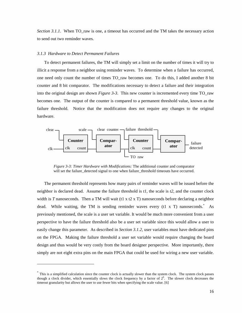
3.1.3 Hardware to Detect Permanent Failures
To detect permanent failures, the TM will simply set a limit on the number of times it will try to
illicit a response from a neighbor using reminder waves. To determine when a failure has occurred,
one need only count the number of times TO_raw becomes one. To do this, I added another 8 bit
counter and 8 bit comparator. The modifications necessary to detect a failure and their integration
into the original design are shown Figure 3-3. This new counter is incremented every time TO_raw
becomes one. The output of the counter is compared to a permanent threshold value, known as the
failure threshold. Notice that the modification does not require any changes to the original
hardware.
The permanent threshold represents how many pairs of reminder waves will be issued before the
neighbor is declared dead. Assume the failure threshold is t1, the scale is t2, and the counter clock
width is T nanoseconds. Then a TM will wait (t1 x t2 x T) nanoseconds before declaring a neighbor
dead. While waiting, the TM is sending reminder waves every (t1 x T) nanoseconds.* As
previously mentioned, the scale is a user set variable. It would be much more convenient from a user
perspective to have the failure threshold also be a user set variable since this would allow a user to
easily change this parameter. As described in Section 3.1.2, user variables must have dedicated pins
on the FPGA. Making the failure threshold a user set variable would require changing the board
design and thus would be very costly from the board designer perspective. More importantly, there
simply are not eight extra pins on the main FPGA that could be used for wiring a new user variable.
* This is a simplified calculation since the counter clock is actually slower than the system clock. The system clock passes though a clock divider, which essentially slows the clock frequency by a factor of 29. The slower clock decreases the timeout granularity but allows the user to use fewer bits when specifying the scale value. [6]
Counter
clk clk count
Compar-ator
scale
TO raw
Figure 3-3: Timer Hardware with Modifications: The additional counter and comparator will set the failure_detected signal to one when failure_threshold timeouts have occurred.
clear
Compar-ator
failure thresholdclear counter
Counter
clk countfailure
detected

17
If a user wants to change the failure threshold under the current implementation, the user must use
the Mentor Tools to modify the actual VHDL source and then recompile and resynthesize the entire
main FPGA.
Another alternative was investigated to make the failure threshold a user variable without
modifying the board. One could multiplex the data lines shown in Figure 3-1. To do this we would
need to store the failure threshold and two other eight bit user variables on the main FPGA (which
could cause capacity problems). Upon reset, the routing FPGA would get all three user variables
from the PROM and temporarily store them. The main FPGA would use two bits to indicate which
of the three variables it was ready to receive and then the routing FPGA would send the appropriate
variable across data lines to the main FPGA. The main FPGA would then store this first variable,
indicate which variable was next, and wait for the routing FPGA to send it across the same data
lines. In this way the main FPGA would get all three variables from the routing FPGA and store
them locally. Problems with this strategy included the added complexity and the need to modify the
routing FPGA. For these reasons it was chosen to proceed with a hardcoded failure threshold. The
idea, however, of storing a user variable on the main FPGA will become useful in the next section.
3.2 HANDLING FAILED NEIGHBORS
The first section of this chapter discussed the modifications that detected when a failure had
occurred. The ultimate result is that when a neighbor has failed the failuredetected signal becomes
one. This section will address how we can use the failuredetected signal to initiate the severing of
the failed neighbor from the isotach network. Before the actual modification can be discussed, some
additional background will be presented.
18
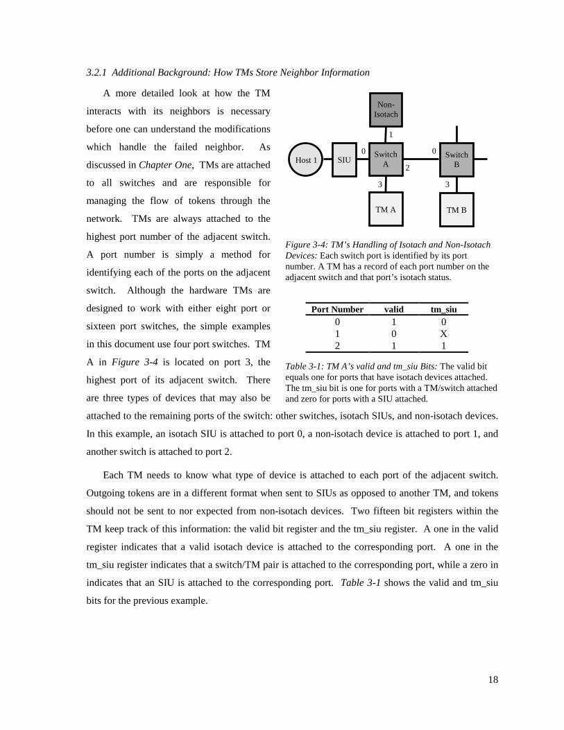
3.2.1 Additional Background: How TMs Store Neighbor Information
A more detailed look at how the TM
interacts with its neighbors is necessary
before one can understand the modifications
which handle the failed neighbor. As
discussed in Chapter One, TMs are attached
to all switches and are responsible for
managing the flow of tokens through the
network. TMs are always attached to the
highest port number of the adjacent switch.
A port number is simply a method for
identifying each of the ports on the adjacent
switch. Although the hardware TMs are
designed to work with either eight port or
sixteen port switches, the simple examples
in this document use four port switches. TM
A in Figure 3-4 is located on port 3, the
highest port of its adjacent switch. There
are three types of devices that may also be
attached to the remaining ports of the switch: other switches, isotach SIUs, and non-isotach devices.
In this example, an isotach SIU is attached to port 0, a non-isotach device is attached to port 1, and
another switch is attached to port 2.
Each TM needs to know what type of device is attached to each port of the adjacent switch.
Outgoing tokens are in a different format when sent to SIUs as opposed to another TM, and tokens
should not be sent to nor expected from non-isotach devices. Two fifteen bit registers within the
TM keep track of this information: the valid bit register and the tm_siu register. A one in the valid
register indicates that a valid isotach device is attached to the corresponding port. A one in the
tm_siu register indicates that a switch/TM pair is attached to the corresponding port, while a zero in
indicates that an SIU is attached to the corresponding port. Table 3-1 shows the valid and tm_siu
bits for the previous example.
Port Number valid tm_siu 0 1 0 1 0 X 2 1 1
Switch A
Switch B
TM A TM B
Figure 3-4: TM’s Handling of Isotach and Non-Isotach Devices: Each switch port is identified by its port number. A TM has a record of each port number on the adjacent switch and that port’s isotach status.
Host 1
Non- Isotach
SIU
1
0
2 3
0
3
Table 3-1: TM A’s valid and tm_siu Bits: The valid bit equals one for ports that have isotach devices attached. The tm_siu bit is one for ports with a TM/switch attached and zero for ports with a SIU attached.

19
3.2.2 Buffering the Valid Bits
The TM can essentially sever a neighbor from the isotach network by changing the valid bit
associated with the neighbor from a one to a zero. Once this change is made, the TM will no longer
expect tokens from or send tokens to the severed neighbor. Notice that the neighbor is not
physically severed from the network but is instead logically severed.
In the original implementation, the valid bits mentioned in the previous section would be set
prior to operating the TM, stored in the routing FPGA, and statically linked to the main FPGA. The
problem is that one wants to modify the valid bits (to severe a failed neighbor) but the bits are not
stored on the main FPGA. There is no way in the original implementation to tell the routing FPGA
to modify a stored user variable since the original design engineer had not anticipated this need. To
solve this problem, the valid bits are buffered on the main FPGA. The bits are initialized to the
PROM user value on reset, and then can be modified by the logic when a failure occurs.
The next issue is knowing which valid bit to change. The failure detection discussed in Section
3.2.1 results in a single bit signal. It is not possible from this single signal to determine which port
and the correspondingly which device is not responding. A careful analysis of the original design
[see Appendix A] reveals that the port state machines (PSMs) contain the necessary information with
which the logic can determine which device failed. The PSM state diagram is shown in Figure 3-5.
There is one PSM for each port of the adjacent switch.
The port state machine works as follows. When the PSM is waiting for a return token from the
corresponding device it stays in state s1 and the send_auth signal is zero. Once the token is
received, the PSM moves into state s0 and send_auth becomes one. When the send_auth for all
fifteen PSMs is one, the TM knows it has successfully received a full token wave and can increment
the local clock and send out a new wave. Once the new wave has been sent, the PSM moves back
into s1 to wait for the next token. Thus the send_auth signals contain the information needed to
s0
send_auth = 1
s1
send_auth = 0
If received a token on corresponding port
After a token wave is finished being sent
Reset
Figure 3-5: Port State Machine: These finite state machines monitor each port of the adjacent switch and indicate when a token has been received.

20
determine which port is not responding. If a failure is detected, then whichever PSM’s send_auth is
zero corresponds to the failed neighbor.
Combinational logic is placed in front of the buffered valid bits that allow the TM to initialize
the valid bits, and modify the correct bit according to the send_auth signals. This logic requires a
new state machine to issue reset and enable signals at the correct time. This new state machine,
called the failure state machine (FSM) will be discussed in the next section. The required
combinational logic for a single buffered valid bit is shown in the VHDL segment below.
if ( reset = '1' ) thennewvalue <= initialval;
elsenewvalue <= sendauth AND laststored;
end if;
This piece of logic has one output signal, newvalue, and four input signals: reset, initialval,
sendauth, and laststored. The output signal is directly wired to the load lines of the valid bit buffer.
The reset signal is not the global reset, and instead comes from the FSM when the valid bits need to
be initialized to the value from the PROM. The intialvalue is attached to the external pins that are in
turn wired to the routing FPGA. This value is the initial user specified valid bit. It makes sense to
reinitialize the buffered valid bits upon reset since a user will probably reset the network once the
failed component is fixed. If the failed component is still down after the reset, the normal failure
detection mechanism simply redetects the failure. The sendauth signal is the same as the send_auth
signal mentioned above and the laststored signal is simply the current output from the buffer.
The logic output will change from one to zero when sendauth is zero indicating the
corresponding port has not received a token. This value will not be loaded into the valid bit buffer
until the FSM enables the buffer. Notice that once a valid bit has changed to zero it cannot change
back to one since the laststored stored signal will always be zero. The only way to revalidate a port
is to reset the entire machine.
A nice consequence of using the send_auth signal to determine which port is invalid is that the
system can detect several failed neighbors in parallel. If two neighbors fail at the same time, the
failure will be detected and both valid bits will be set to zero.

21
3.2.3 Failure State Machine
The failure state machine (FSM) shown in Figure 3-6 provides the timing and control for the
hardware discussed above: the counter and the valid bits buffer. The FSM begins in state f0 where
the validreset and clear_counter signals are one. These signals set the counter discussed in Section
3.1.3 to zero and set the reset signal discussed in Section 3.2.2 to one. On the next clock cycle, the
FSM moves into state f1 where all output signals are zero. The FSM stays in state f1 until the
failuredetected signal goes to one. This moves the FSM into state f2 where it will clear the counter.
States f3 and f4 are needed for the set_errsig and will be discussed in the next chapter. Once
finished, the FSM returns to state f1. Notice that the valid buffer bits are only initialized in state f0
and thus only after a reset. The FSM integrated with the hardware described in the above sections
integrated into the overall TM is shown in Chapter 6.
3.2.4 Modifying the Port State Machines
The design so far is enough to detect the failure and to change the correct valid bit, but
unfortunately the PSMs for the failed neighbor will remain in state s0. This is because the transition
from s0 to s1 is not based directly on the valid bits but relies instead on a separate register. Details
can be found in Appendix A. The key point is that we need a way to push the PSM back into state s0
after an error has been detected so that the TM will send out the next token wave. To do this the
PSM was modified such that it includes the failuredetected signal as a new input signal. The
transition from state s1 to s0 now occurs if the appropriate token has been received or if the failure
detected signal becomes one. The current configuration skips sending the last two reminder waves
when a failure has been detected, since these waves would be ignored by all valid devices and would
not be sent to the failed device.
* The final failure state machine is slightly more complex than the one shown in this figure, since it includes the set_errsig signal. The final failure state machine with the set_errsig signal will be discussed in Chapter 4.
f0
[11]
f1
[00]
f2
[01]
failuredetected
Reset Output signals: [ validreset, clear counter ]
Figure 3-6: Failure State Machine*: This state machine controls the failure counter and the valid bits buffer.

22
Chapter Four
Notifying Hosts of a Failed Neighbor This chapter examines the design, implementation, and testing of the second of the three hardware modifications. This modification allows a TM to broadcast a one bit error signal to all hosts in the network. The current isotach signal architecture was modified to allow timely propagation of the error signal and a mechanism for resetting the error signal.
4.1 ADDITIONAL BACKGROUND: ISOTACH SIGNALS
A signal is a broadcast communication mechanism issued by an isotach host and delivered
synchronously to all other hosts in the system [15]. The isotach specification requires that a signal
be delivered to all hosts at the same logical time. In order to guarantee proper delivery, isotach
devices monitor a higher order logical time unit know as epochs. If a token wave is analogous to a
second, then an epoch is analogous to a minute. The epoch length depends on the size of the
network, and is thus stored on the PROM mentioned in Section 3.1.1. As defined in the isotach
design specification, “An epoch is some number of local time pulses (determined when the system is
configured) greater than the diameter of the network.” [15]
The six isotach signals are implemented as a six bit field in the standard token definition. Each
of the first five bits correspond to application level signals, while the last bit is reserved as a system
wide reset signal. When a host issues a signal, the corresponding SIU will store the signal and wait
until the next epoch boundary before sending the signal on to the network. The token with the
signal bit set will make its way to the next TM along the route, where that TM will store the signal
bit. From then on the TM will issue token waves with the appropriate signal bit set. Since the
epoch length is greater than the diameter of the network, all SIUs in the system will eventually
receive the signal before the next epoch boundary. At the next epoch boundary, all SIUs pass the
signal on to their respective hosts. In this way, the signal propagates through the network and is
delivered to all hosts at the same logical time. TMs clear their stored signal bits at the each epoch
boundary so that new signals can be propagated in the next epoch. It is important to note that the
entire signal architecture assumes that only hosts can initiate a signal. [15]
23
4.2 DESIGN ALTERNATIVES
Chapter Three outlines the modifications necessary to handle a failed neighbor locally.
Although a TM can detect and sever a failed neighbor, hosts will continue to operate under the
assumption of a completely functioning network. Hosts may need to redistribute the work load or
begin using a replicated data storage in light of the failure. Thus, there is a need to elevate the
failure from the local hardware level to the higher host application level for more complex failure
handling. To address this need, I implemented a mechanism that allows TMs to notify all hosts in
the system of a failure. The primary requirements for the failure notification method is that it be
both timely and robust.
The TM notification mechanism was constrained by the current isotach architecture. A possible
solution might be for TMs to store the routing information to each host and then to issue a special
message directly to each host whenever a failure occurred. This alternative, however, would require
drastic changes to the current implementation. My modifications needed to be subtle and exploit the
current isotach functionality. I decided to use isotach signals as the method for notifying hosts of
the failure. A disadvantage of this decision is that using signals for notification reduces the number
of application level signals available for normal use.
The primary problem with isotach signals as a notification mechanism is that the signals were
designed to be issued by hosts not TMs. If a TM simply set a specific signal bit whenever a failure
occurred, the epoch boundaries would interfere with the proper delivery of the error notification.
For example, if a TM issued a failure notification near the end of an epoch, the signal may be
cleared at the epoch boundary before it reaches all the hosts. One way to resolve this problem is to
implement all signals such that they no longer use epochs, but this would require significant
modifications to both the TM and the SIU.
A very simple alternative is for the TM to wait until the next epoch boundary before sending the
notification signal. This alternative is advantageous, since it guarantees all hosts in the system will
learn of the failure at the same time. However, it also artificially delays delivery of the notification.
A better alternative is to remove the failure notification signal from the epoch constraints so that it is
not cleared at the epoch boundaries. In this way, the notification reaches each host’s SIU as soon as
possible. The SIUs still buffer the failure signal until the next epoch boundary, so the SIUs would
have to be modified to allow failure notifications to be sent to the host any earlier than the nearest
epoch boundary.

24
An important concern is that hosts are notified of the failure before any illegal messages reach
the host. Illegal messages are messages that originate from outside the LVR and thus do not abide
by the isotach causal guarantees. This is why the SIU would probably have to be modified to allow
failure notifications to reach the hosts as soon as possible. If the SIU waits until an epoch boundary
to deliver the failure notification, then an illegal message may have already slipped though while the
notification was pending. Of course this discussion assumes that illegal messages are not sent until
after a TM has sent several reminder waves and eventually declared the neighbor dead.
I chose to use a two bit failure notification mechanism. The TM sets the first bit, called err_sig,
when a failure is detected, and it propagates to the SIU without concern for epoch boundaries. This
notification will reach the SIU/host pair as soon as possible. The second bit, called err_clr, is
issued by a host and propagates as a normal isotach signal. TMs clear their err_sig bit when they
receive an err_clr signal. Err_clr signals also provide a uniform logical time for the failure, which
allows hosts to agree when the failure occurred.
4.3 MODIFICATIONS TO THE SIGNAL LOGIC
Normal isotach signals are stored in a buffer, called sig_buf, in the TM. As described above, the
sig_buf is cleared at each epoch boundary. Some combinational logic before each bit of the sig_buf
controls when the bits change. For normal signals this combinational logic implements the
following boolean equation where: S(i) is bit i in the sig_buf, P(i) is true when the most recently
received token wave contained at least one token with signal bit i set to one, and E(i) is true at the
epoch boundary.
S(i) = (NOT E(i)) AND (P(i) OR S(i)) [eq 1]
To bring a signal outside the epoch constraint so that it is not cleared at each epoch boundary one
need only modify this equation as follows:
S(i) = P(i) OR S(i) [eq 2]
The err_sig is defined to be signal bit 5, while the err_clr signal is defined to be signal bit 4. The
err_sig has the additional constraint that it becomes one if a failure is detected and is cleared if the
err_clr signal is true. If we let F indicate that a failure has been detected (F corresponds to the
failure_detected signal discussed in Section 3.1.3), then the following equation indicates the
combinational logic required to implement the err_sig.
S(5) = (NOT S(4)) AND (P(5) OR S(5) OR F) [eq 3]

25
Modifying the combinational logic to implement equation 3 was largely trivial, and the final result is
shown in Figure 4-1. This figure is a magnified view of the actual TM schematic. Notice that the
err_clr signal is implemented as a normal isotach signal.
Figure 4-1: Schematic of Err_sig and Err_clr Combinational Logic: Implementing the err_sig signal required modifications to the combinational logic that precedes bit 5 in the sig_buf. The err_clr signal was implemented as a normal isotach signal. This is a screen capture of the actual modified TM schematic.
The problem with this approach is that the err_sig signal will be set to one on the wrong clock
cycle. The combinational logic will correctly output a one, but the sig_buf will not be enabled until
two clock cycles later when the next token wave is issued. The result is that the err_sig is never
sent. To fix this, I needed to modify the failure state machine discussed in Section 3.2.3.
err_sig
err_clr
set_errsig
Signals from most recently received token wave
epoch_boundary
From previous sig_buf values

26
4.4 MODIFICATIONS TO THE FAILURE STATE MACHINE
To make sure that the err_sig was one the same clock cycle the sig_buf was enabled, I needed to
delay the failure_detected signal. I also needed to avoid disturbing the timing established in the
previous set of modifications. Therefore, two additional states and a new output signal were added
to the FSM originally presented in Section 3.2.3. This new output signal, set_errsig, is one for two
additional clock cycles after the failure is first detected. Thus, the set_errsig signal is used for F in
equation 3 instead of the failure_detected signal. Changing the combinational logic before the
sig_buf and modifying the FSM were all that was needed to allow the TM to issue a failure
notification to the hosts.
f0
[110]
f1
[000]
f2
[011]
f3
[001]
f4
[001]
failuredetected
Reset Output signals: [ validreset, clear_counter, set_errsig ]
Figure 4-2: Modified Failure State Machine: The FSM presented in Section 3.2.3 was modified so that the set_errsig signal could be held long enough to be loaded into the sig_buf.

27
Chapter Five
Token Manager Ping The third modification allows a host to specifically determine which TM has failed. A signal bit notification fits well within the current system architecture, yet fails to provide enough information for a host to appropriately address the failure. This chapter examines the final modification, which enables a host to send a special message to a TM in order to verify the TM’s operational status. When a TM receives this special message, known as a ping, it will return the message to the host. If the host does not receive the returned message, it knows the corresponding TM has failed.
5.1 ADDITIONAL BACKGROUND: MYRINET ROUTING FLITS
TMs and other devices in the network
send messages by attaching eight bit
routing flits to the front of the message. A
flit refers to a byte used explicitly for
routing through switches. For example in
the network shown in Figure 5-1, if TM A
wishes to send a token to the SIU attached
to port 0, it would need to place a single
routing flit at the beginning of the message.
This flit would direct the switch to take the
message from port 3 and route it to port 0.
In the process of routing the token, the
switch strips the flit from the front of the message, and thus the SIU receives just the token with no
routing flits. For TM A to send a token to TM B, as is indicated by the dark arrow in the figure, it
must add two routing flits: one to move the token through switch A and another to move the token
through switch B. The first flit would indicate a port 3 to port 2 route while the second flit would
indicate a port 0 to port 3 route. The key concept is that these routing flits allow messages to move
through the network, and a flit is stripped off at each Myrinet switch.
Switch
A Switch
B
TM A TM B
Host 1
Non- Isotach
SIU
1
0
2 3
0
3
Figure 5-1: How Messages are Routed in Myrinet: Each message has an eight bit flit to direct each Myrinet switch how to route the message through that switch.

28
5.2 GENERAL PING CONCEPT
A ping is similar to a self-addressed envelope (SAE). Assume Person A wants to see if Person
B is healthy. Person A might send a brief message and a SAE inside a normal envelope to Person B,
and ask Person B to return the SAE. Notice that Person A must provide the address of Person B and
the return address. If Person A does not receive the SAE, Person B can be assumed to be unhealthy.
A ping operates on the same principle: a host sends a ping that contains the routing information to
get to a specific device, a brief message, and the routing information to return to the host.
The failure notification mechanism described in Chapter 4 will indicate to a host that a failure
has taken place, yet it does not specify which particular isotach device is no longer operational. A
host needs a way to determine which specific TM has failed.
Tokens cannot act as pings since they are a fixed length and lack the space necessary for the
routing information. A possible solution is to create a new type of message specifically designated
for TM pings, yet this would require special permission from Myrinet for the new message type. A
much simpler solution can be found if one observes the difference between isotach tokens and
isotach messages. Tokens are handled by both TMs and SIUs, but isotach messages are normally
only seen by SIUs. Under the current implementation, a TM will simply discard any isotach
messages it receives. I therefore decided that when a TM receives an isotach message it should
interpret it as a TM ping. This solution works within the current system architecture and does not
require any modifications to the SIU.
5.3 STRUCTURE OF A PING MESSAGE
A TM ping message consists of the following four parts: the route from the host to the TM, the
isotach message type identifier, the route from TM to the host, and a brief message. The message
shown in Figure 5-2 is the format for a ping when it is first issued from a host. Figure 5-2 also
illustrates an example where host 1 wants to ping TM B to determine if it has failed. The first part
of the ping message is the routing information necessary for the ping to get to the TM, and it is
removed as the ping moves through the various Myrinet switches. In the example, there are two
routing flits required to move the message from host 1 to TM B: one for switch A (port 0 to port 2)
and one for switch B (port 0 to port 3). When the ping message reaches TM B, the initial routing
flits will have been completely stripped off leaving the last three parts. The second part of the ping
message is simply an isotach message type identifier, which is removed by the TM, while the third
part is the return routing information. By the time the ping has returned to host 1, all that will

29
remain is the dummy message. The dummy message can contain any unique value, and it enables
the original host to differentiate between multiple pings. The main issue in such a design is
handling the return routing information within the TM. Two possible solutions will be examined in
the next section.
5.4 TWO METHODS FOR HANDLING RETURN ROUTE INFORMATION
The TM needs to perform the following four steps in order to correctly handle host-to-TM pings:
1. Recognize that the current incoming word is the first word in a ping. 2. Remove the two byte isotach message type identifier. 3. If a token wave is currently being issued, wait until the wave is finished. 4. Pass the ping (return route information and dummy message) back onto the network.
Step one was simply an issue of modifying the logic that examines the token type identifier, and step
two was trivial. Step four required modifying the state machines that monitor sending token waves
so as to allow the output lines to serve a dual purpose: issuing token waves and returning pings.
Step three, however, provided an interesting challenge.
The incoming network traffic comes through a first in first out buffer (FIFO) before it reaches
the actual main FPGA. This FIFO prevents the FPGA from missing anything if the incoming
network traffic is arriving too quickly. Kuebert decided to permanently wire the FIFO such that it
was always enabled [7]. This means the FIFO will always output one word to the main FPGA every
clock cycle. This was a reasonable decision in the original implementation, since the TM is
designed to always accept input. This input is either discarded if it is not a token, or the applicable
Route to TM (up to 5 bytes) Route back to host (up to 5 bytes)
Isotach message type identifier
(2 bytes)
Dummy message (1 byte)
Figure 5-2: A TM Ping Message: A ping begins with four parts. As the ping travels to the TM, the initial routing information is stripped off. The TM removes the isotach message type identifier and puts the remaining two parts back on the network. When the ping returns to the SIU, all that remains is the dummy message.
Switch A
Switch B
TM A TM B
Host 1
Non- Isotach
SIU
1 0 2
3
0
3
0 -> 2 : 0 -> 3 3 -> 0 : 2 -> 0

30
token information is buffered. With respect to the host-to-TM ping situation, however, it would be
useful if the main FPGA could force the input FIFO to pause for several clock cycles. This would
allow the main FPGA to finish sending the current token wave and then enable the input FIFO when
the output lines were available. The ping return route information could then be directly passed
through to the output lines one word at a time irrespective of the actual length of the overall ping.
The fact that this solution does not constrain the length of a host-to-TM ping allows any host to ping
any TM in the network.
The first step to allow the FPGA to pause the FIFO is to sever the permanent connection
between the FIFO enable and ground. This connection is actually a piece of metal embedded in the
PCB board, but it can be broken with a special knife. A physical wire is used to attach the FIFO
enable pin to a free pin on the main FPGA. This connection is much less reliable than a permanent
embedded connection, but it is a common technique used in constructing prototypes. The FPGA
logic could then directly enable or disable the FIFO. The main problem with such a solution is that
it requires drastic modifications to the PCB. I decided to sacrifice the flexibility of unlimited size
ping messages in order to achieve a less intrusive modification.
An alternative to forcing the FIFO to wait until the current token wave is sent is to simply buffer
the ping message until the ping can be returned. This requires the designer to set a limit as to the
size of the ping. After discussions with the isotach architects, I decided that a limit of two words for
the ping message would be more than adequate. Two 32 bit words contain eight bytes. Two of
these bytes would be reserved for the isotach message type identifier and at least one would be
required for the dummy message. This leaves a maximum of five bytes for the return routing
information, and correspondingly, this limits a host’s ability to ping TMs. A host can only ping a
TM that is within five switches. Although every host will not be within five switches of every TM,
it is highly unlikely that there will be a TM that is not within five switches of at least one host. This
realization means that all hosts can still learn the status of all TMs if one takes a distributed
approached to discovering the failed TM.
As an example, consider a large network with several TMs and hosts. All hosts receive a failure
notification signal and thus all hosts would like to determine which specific TM or SIU has failed.
To do so, each host has a few TMs (within five switches) and SIUs for which it is responsible. The
host determines the status of all devices for which it is responsible and broadcasts this information
to the other hosts. The hosts can work together to quickly identify the failed device.

31
The buffered return route approach constrains the size of the host-to-TM ping in two ways. As
discussed above, the total size of the host-to-TM ping cannot exceed 13 bytes: five bytes for routing
to the TM, five bytes for routing from the TM back to the host, two bytes for the isotach message
identifier, and one byte for the dummy message. The minimum host-to-TM ping size is also
constrained, since my modifications assume that the TM needs to buffer two words. This is only a
concern when a host is pinging a TM on the same adjacent switch (such as host 1 and TM A in
Figure 5-2). In this case, the total host-to-TM ping size would be five bytes: one byte for routing to
the TM, one byte for routing from the TM back to the host, two bytes for the isotach message
identifier, and one byte for the dummy message. The problem is that when this ping reaches the TM
it will only be one word long, since the first routing flit will have been stripped away. The TM,
however, expects all pings to be two words. Therefore, when a host needs to ping a TM on the same
adjacent switch, it should make the dummy message two bytes long. This guarantees that the TM
will always have two words of ping information to buffer.
5.5 MODIFICATIONS TO THE INPUT STATE MACHINE AND THE RETURN ROUTE BUFFERS
Figure 5-2 shows the modified input valid
state machine (IVSM). The original state
machine was comprised of only states s0 and
s1. State s2 was added to handle host-to-TM
pings. The state machine begins in state s0.
Two separate blocks of logic control the
buff_en and ping_valid signals. Buff_en will
be one if the current word from the input FIFO
is the first word of a token, while ping_valid
will be one if the current word is the first word
of a host-to-TM ping. As discussed above, the
first two bytes of the first word of a host-to-TM
ping will be the isotach message identifier. Once the state machine enters either state s1 or s2, it
will set either ping_recv or inp_valid to one. These output signals are used as enables for various
buffers, which store parts of the incoming word from the FIFO.
A 16 bit buffer and a 35 bit buffer are used to store the return route. Since two bytes of the first
word of a host-to-TM ping are the isotach message identifier, one need only store the last two bytes
of the first word. The entire second word of the host-to-TM ping must be buffered. The enable for
Figure 5-3: Modified Input Valid State Machine: This state machine controls the movement of words from the input FIFO into the rest of the TM. State s2 was added.
s0
[00]
s2
[10]
s1
[01]
buff_en = 1
ResetOutput signals:
[ ping_recv, inp_valid ]
ping_valid = 1
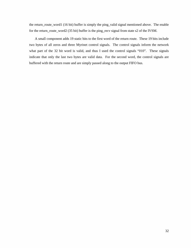
32
the return_route_word1 (16 bit) buffer is simply the ping_valid signal mentioned above. The enable
for the return_route_word2 (35 bit) buffer is the ping_recv signal from state s2 of the IVSM.
A small component adds 19 static bits to the first word of the return route. These 19 bits include
two bytes of all zeros and three Myrinet control signals. The control signals inform the network
what part of the 32 bit word is valid, and thus I used the control signals “010”. These signals
indicate that only the last two bytes are valid data. For the second word, the control signals are
buffered with the return route and are simply passed along to the output FIFO bus.

33
5.6 THE PING HANDLER STATE MACHINE
The ping handler state machine (PHSM) is responsible for getting the return route information
from the buffers to the output FIFO. The PHSM begins in state p0 where it remains during all
normal TM activity. When a host-to-TM ping is received (ping_recv from the IVSM is one), then
the PHSM moves into state p1 where it will wait until the current token wave has been issued.
While in state p1, the PHSM lets the master state machine know a ping has been received with the
ping_waiting signal. The send_ping signal comes from the master state machine, and it indicates
that the all token waves have been sent. The PHSM now moves into state p2 or state p3 depending
upon whether or not the output FIFO is ready. If the FIFO is not ready, the PHSM will simply wait
in state p3 until it is ready. In state p2, the PHSM puts the first word of the return route information
into the output FIFO and then repeats the same procedure with states p4 and p5 for the second word.
Once both words have been placed into the output FIFO, the PHSM returns to state p0.
Figure 5-4: Ping Handler State Machine: This state machine controls the movement of the return route flits from the buffers to the output FIFO. There are four output signals: ping_waiting tells the MSM to pause as soon as possible, the two sel signals control muxes at the output FIFO lines, and output_valid tells the output FIFO when the data is ready.
p0
[0000]
p3
[1101]
p2
[1100]
Reset
Output signals: [ ping_waiting, ping2fifo_sel, ping_word_sel, output_valid ]
send_ping = 1 & fifo_ready = 1
p5
[1111]
p4
[1110]
fifo_ready = 1
fifo_ready = 0
p1
[1000]
ping_recv = 1
send_ping = 1 & fifo_ready = 0
fifo_ready = 1
fifo_ready = 1
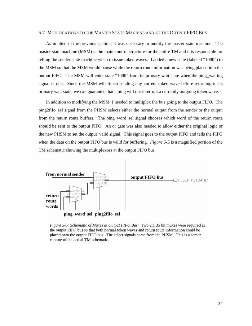
34
5.7 MODIFICATIONS TO THE MASTER STATE MACHINE AND AT THE OUTPUT FIFO BUS
As implied in the previous section, it was necessary to modify the master state machine. The
master state machine (MSM) is the main control structure for the entire TM and it is responsible for
telling the sender state machine when to issue token waves. I added a new state (labeled “1000”) to
the MSM so that the MSM would pause while the return route information was being placed into the
output FIFO. The MSM will enter state “1000” from its primary wait state when the ping_waiting
signal is one. Since the MSM will finish sending any current token wave before returning to its
primary wait state, we can guarantee that a ping will not interrupt a currently outgoing token wave.
In addition to modifying the MSM, I needed to multiplex the bus going to the output FIFO. The
ping2fifo_sel signal from the PHSM selects either the normal output from the sender or the output
from the return route buffers. The ping_word_sel signal chooses which word of the return route
should be sent to the output FIFO. An or gate was also needed to allow either the original logic or
the new PHSM to set the output_valid signal. This signal goes to the output FIFO and tells the FIFO
when the data on the output FIFO bus is valid for buffering. Figure 5-5 is a magnified portion of the
TM schematic showing the multiplexors at the output FIFO bus.
Figure 5-5: Schematic of Muxes at Output FIFO Bus: Two 2:1 35 bit muxes were required at the output FIFO bus so that both normal token waves and return route information could be placed onto the output FIFO bus. The select signals come from the PHSM. This is a screen capture of the actual TM schematic.
ping2fifo_selping_word_sel
from normal sender
return route words
output FIFO bus

35
Chapter Six
Results: Schematics, Simulation, and Synthesis The previous three chapters individually outlined the design and implementation for the three modifications. This chapter views the modifications from a system perspective in order to analyze their impact on the overall TM schematic, TM functionality, and FPGA constraints. First, the original and modified TM schematics are presented. Second, a few illustrative functional tests are discussed to demonstrate that the modifications perform as expected. The last section describes the results from synthesizing the modified TM.
6.1 THE TOKEN MANAGER SCHEMATICS
As discussed in Chapter 1, the Mentor Graphics tools allow a developer to connect various
VHDL components in a system schematic. This provides a graphic depiction of how the sub-
components are interconnected. I have included both the original schematic and the modified
schematic. The original schematic can be found in Figure 6-1, and it is annotated to denote the
various parts of the TM. The TM can be divided into three main regions: the receiver, the control
unit, and the sender. The receiver is responsible for storing the information contained in each
incoming token, while the sender is responsible for managing the issue of token waves. The control
unit coordinates the receiver and the sender and monitors device timeouts. [More detail on the
original hardware can be found in Appendix A] This figure clearly indicates the need for a detailed
study of the original hardware before attempting modifications. With a system this complex, each
component is closely interrelated with several other components. When modifying the TM, I was
required to carefully consider each modification’s impact on the rest of the system.
Figure 6-2 shows the TM schematic after all three modifications have been fully implemented.
Each modification is highlighted in a different color. Notice the wide scope of the modifications. I
modified several of the original finite state machines and created several new components.

36

38
6.2 FUNCTIONAL SIMULATION
Using a VHDL simulator, I was able to functionally verify that the modifications performed as
expected. The simulations began with a script file that instructed the simulator on the initial values
for the signals in the system. [The script files can be found in Appendix B] The simulator uses the
script file to simulate the entire TM and produce a waveform trace. These traces illustrate what is
going on inside the TM and help the developer determine if the TM is functioning correctly. Two
functional tests are included in this chapter to illustrate the functional correctness of my
modifications. The first test examines the failure detection and notification, and the second test
examines the host-to-TM ping handling.
The first test is shown in Figures 6-3, 6-4, and 6-5. Figure 6-3 illustrates the complete
procedure for failure detection, handling, and notification. The test begins with the TM issuing its
first token wave, and the script file artificially responds by sending tokens back to the TM. Notice
that the send_auth signal has one zero indicating that the TM is waiting to receive a token from that
device. The timeout signal goes high, and so the TM issues a reminder wave. The neighbor still
does not respond, and the TM experiences another timeout. This time the failure_counter has
reached the failure_threshold, so the TM declares the unresponsive neighbor dead. Examining the
valid_buf signal shows how the TM switches the bit corresponding to the unresponsive neighbor
from a one to a zero. The sig_buf shows that the TM sets the err_sig bit to one in order to notify
hosts of the failure. The TM issues a new token wave (with the err_sig bit set) and will neither
expect tokens from nor send tokens to the dead neighbor. The script file responds by having the
valid neighbors send tokens back to the TM. I have setup the test such that this token wave also
includes the err_clr signal. Correspondingly, the err_sig bit is cleared. Notice that the err_clr signal
is cleared as a normal isotach signal at the end of the epoch. Figure 6-4 shows a magnified area of
the trace when the failure is detected. Figure 6-5 is a trace from a slightly different script file. This
figure verifies that the err_sig is not cleared at epoch boundaries. As discussed in Chapter 4, this is
a key requirement for timely failure notification.

39

40

42
The second test examines the host-to-TM ping. Figures 6-6 and 6-7 illustrate how the TM
handles the ping. Figure 6-6 shows a ping arriving at the TM on the from_fifo lines. The
ping_valid signal goes high indicating that this ping has the correct ping message identifier, and
therefore the TM buffers the return route information (as illustrated by the return_route_word1 and
return_route_word2 signals). The TM then places each of the two words onto the to_fifo lines. The
entire ping handling process takes seven clock cycles.
Figure 6-7 demonstrates how the TM handles a ping when it is received while a token wave is
being issued. The TM cannot immediately put the return route onto the to_fifo lines since the
sender is using these lines. Instead the TM must wait until the token wave is finished before
handling the ping. The from_fifo signals in Figure 6-7 show when the ping is received. Notice that
the ping_waiting signal goes high to remind the TM that it needs to handle the ping once the current
token wave has been sent. Once the sender state machine is done, the master state machine enters
state “1000” (as seen on signal master_sm/state). The return route can be seen on the to_fifo lines.

43

45
6.3 TOKEN MANAGER SYNTHESIS
Synthesis is the process by which VHDL is transformed into the actual FPGA hardware logic.
A real concern was whether or not the modifications would cause the TM to exceed the maximum
capacity of the main FPGA. To address this concern, I used three tools to generate, place, and route
the design: galileo, mapsh, and parsh. These tools provide information on the size of the design
compared to the maximum possible size. Additionally, the parsh tool tries to connect together the
various pieces of hardware logic, and thus it reports on whether or not it was able to route the
design. Some basic timing information can also be gathered from the parsh tool. As described in
Section 1.3.1, a Lucent ORCA or2c40a FPGA was used for the main FPGA. This chip has a
maximum capacity of 900 PFUs. Table 6-1 shows the PFU usage for the original design and after
each of the three modifications.
TM Version PFUs Flip-Flops Combinational LUTs
Original 488 (54%) 459 531 with Modifications #1 482 (53%) 485 486 with Modifications #1, #2 511 (56%) 486 514 with Modifications #1, #2, #3 525 (58%) 542 467
Table 6-1: FPGA Usage: The table illustrates how the modifications impacted the size of the design. The or3c40a FPGA has four flip-flops and four LUTs per programmable function unit (PFU).
Notice that the size of the design in PFUs actually decreases following the initial set of
modifications. This is counterintuitive, since one would think that making additions to a design
would generally make that design larger. The reason for this discrepancy is probably due to the
structure of a single PFU. Each PFU contains four flip-flops. Thus, a whole PFU is considered ‘in
use’ whether one flip-flop is used or all four flip-flops are used. The original design may have had
several PFUs that were not fully exploited, and thus, the modifications simply took advantage of the
unused portions. This might explain why the size would stay the same, but it does not explain why
the size actually decreased. Notice in Table 6-1 that the first set of modifications resulted in an
increase in the number of flip-flops but a decrease in the number of combinational look up tables
(LUTs). The computer tools may have been able to better optimize the combinational logic after the
additions were made. If additional flip-flops were placed in partially used PFUs and additional
combinational logic allowed for further optimization, it is quite possible that the number of PFUs
might decrease after making additions.

46
The key point from Table 6-1 is that all three modifications cause an eight percent increase in
the total PFU usage for the main FPGA. This brings the final FGPA capacity to 58%. Although far
from being completely full, it is important to note that as a design nears 60% capacity, the design
becomes much more difficult to route. Therefore, I also used the parsh tool to verify that the final
design could be routed successfully.
Routing a design is a non-deterministic problem, and therefore, various runs of the parsh tool
can result in different routing. These different interconnects can result in drastically different
design speeds. Brian Kuebert, the electrical engineer responsible for the original TM, used a
conservative single routing pass, and thus, I used a similar method. I also attempted a much more
aggressive routing strategy using several optimization passes. The result was much lower delays
through the TM. These timing results are shown in Table 6-2. It is important to note that this
timing analysis is not particularly accurate and simply allows one to qualitatively examine the
impact of the modifications on the overall design’s speed. As expected, the delay through the TM
increases after the modifications. One area where the modifications definitely slow down the
original design is at the output FIFO bus where I added a 2:1 mux. This mux will introduce an
additional delay in the TM’s primary output path.
TM Version Avg Connection Delay (ns)
Max Delay From Pin-to-Pin (ns)
Original 8.92 41.72 with Modifications 10.13 57.71
Original (multi-pass) 6.00 17.01 with Modifications (multi-pass) 6.59 18.47
Table 6-2: Timing Results: The parsh tool gives basic timing information that can be useful in qualitatively examining the modifications’ impact on the overall TM’s speed. The aggressive
multi-pass routing strategy produced much better timing results.

47
Chapter Seven
The Logical Dead Space Problem Dead space is a consequence of the modifications discussed in Chapter 1. It refers to an area of the network where logical time has stopped (the inverse of the LVR). The underlying problem is that although tokens are barred from entering dead space (through the Chapter 1 modifications), isotach messages are not similarly constrained. This means that a host in the LVR could receive an isotach message originating outside the LVR, which could easily violate causal guarantees. The dead space problem was one of the main reasons failed neighbor handling was not included in the original prototype, thus this chapter explains how the three modifications presented in the previous chapters can work together to address this problem.
7.1 WHAT IS DEAD SPACE?
Figure 7-1 illustrates a typical dead space
scenario. The circles represent a host/SIU pair,
while the squares represent TMs and SIUs. The
key to understanding dead space is the difference
between how isotach tokens and isotach messages
propagate through the network.
As discussed in earlier chapters, tokens move
from TM to TM to SIU in the form of token
waves. SIUs handle tokens exactly like a TM:
when they receive a token they increment their
internal logical clock and send a new token with
the incremented timestamp. Isotach messages,
however, do not move from TM to TM. Instead they simply move through the Myrinet switches like
normal network traffic until they reach the target host’s SIU where they are buffered. For example,
assume that TM 2 has not failed in Figure 7-1. Then a token moving from host 1’s SIU would move
through switch 1 (S1) and stop at TM1. It would then move through switch 2 (S2) and stop at TM2,
Figure 7-1: Dead Space: Dead space, the inverse of the LVR, can cause problems since tokens and
isotach messages propagate differently.
H1
H2
S1
H3
S2
H4
S3 H5
Dead Space LVR BLVR A
T1 T2 T3
Tokens Isotach Messages

48
and so on until it reaches host 5’s SIU. An isotach message would simply move through each of the
three switches until it reaches host 5’s SIU.
Now assume TM2 has failed. TM1 and TM2 will both declare TM2 dead and will
correspondingly stop sending tokens to or expecting tokens from TM2. This partitions the network
into two separate and unsynchronized LVRs. The problem is that although tokens can no longer
pass through the logically dead space, isotach messages can freely move between LVRs through the
dead space. Similarly, messages can be generated within the dead space by host 3 and then sent into
the LVRs.
Let us examine the dead space problem with other component failure modes. If the network link
connecting two switches fails or if a switch itself fails, then the network will be physically
partitioned instead of logically partitioned. A physical partition avoids the dead space problem,
since neither tokens nor isotach messages can travel through a failed network link. A network link
failure between a switch and a TM will act the same as a failed TM, and thus, the dead space
problem will still be present. Notice that a failed SIU can cause similar problems, even though the
dead space is not in the middle of the network. The SIU failure could take many forms and even
though it may not be responding to its neighboring TM, it could still allow isotach messages to pass
onto the network. Thus isotach messages are being generated in dead space and then allowed to
travel into the LVR.
The dead space problem is significant since it allows messages to violate the fundamental
isotach synchronization guarantees. The problem seems to outweigh any benefit derived from
handling the failure and allowing a portion of the network to continue to function. The three main
solutions to the dead space problem will be discussed in the next section.
7.2 SOLUTIONS TO THE DEAD SPACE PROBLEM
The first solution to the dead space problem is to simply assume a fault free network. This was
the isotach group’s original strategy, and it is quite reasonable when one considers the probability of
TM or SIU failure. These isotach devices have been thoroughly tested and use highly reliable parts
so that a TM or SIU failure is theoretically unlikely. Unfortunately, there has been no quantitative
analysis of the isotach hardware devices’ reliability. Furthermore, a TM or SIU failure is critical.
Such a failure mode causes the entire isotach network to come to a halt. Providing a mechanism for
handling TM and SIU failure, even though such failures are rare, is important to creating a robust
and fault tolerant isotach implementation.

49
Another solution to the dead space problem is the barrier method. The idea is to create a barrier
in the dead space that prevents isotach messages from passing through. The most drastic possibility
is to force the switch to fail whenever its adjacent TM fails. This would be both difficult to
implement and would hinder non-isotach network traffic. Another possibility is to make isotach
messages propagate from TM to TM in the same way as tokens. When a TM or SIU fails, the
neighboring TM would disregard isotach messages in the same way it disregards tokens and
effectively create a barrier in the dead space. Unfortunately, this solution would require a
completely new implementation of the TM.
The third solution is the invalidation method. The idea is to give a host or SIU in the LVR the
ability to differentiate between messages that originated inside the same LVR and messages that
originated outside the LVR. Adding this capability to the SIU would require extensive hardware
modification. Allowing the host to decide the validity of an isotach message is much more
reasonable. The host could proceed as normal until it receives notification of a failure. The host
would then move into a failure mode where it identifies the failed device and disregards any
messages that originate from outside the LVR. The additional overhead involved in checking the
validity of isotach messages would not be trivial, but it would only be required when a failure has
actually occurred. The three modifications described in Chapters 3, 4, and 5 provide the tools
necessary to implement this solution.
7.3 HOW ALL THREE MODIFICATIONS ADDRESS THE DEAD SPACE PROBLEM
Let us examine the failure scenario presented in the previous section and in Figure 7-1. TM2
has failed and TM1 and TM3 correspondingly send several reminder waves. Once the failure
threshold has been exceeded, both TM1 and TM3 declare TM2 dead and set the appropriate valid bit
to zero. TM1 and TM3 will no longer expect tokens from TM2, nor will they send tokens to TM2.
Both TM2 and TM3 will then set err_sig to one in the next token wave. Hosts 1, 2, 4, and 5 will
receive the notification, but host 3 will be unaware of the failure since tokens cannot enter dead
space. These hosts will then attempt to determine which SIU or TM has failed. Each host will then
ping each of the three TMs to determine which has failed. Notice that all hosts can ping all TMs
since no TM is more than five switches away from all hosts. Pings to TM2 will not be returned
since that device has failed. Once all hosts have determined that TM2 has failed, the hosts should
send an err_clear signal. This signal will reset the err_sig in all working TMs.

50
If a SIU had failed instead of a TM, a host would still ping all TMs first. Once the host had
determined that a TM has not failed, the host could send isotach messages as pings to the other four
hosts in the network. If one of the other hosts did not return the isotach message then that SIU/host
pair is assumed to have failed. Hosts cannot perform this host-to-host pinging first, since hosts in a
dead space caused by a failed TM will be unable to return a direct ping. In Figure 6-1, host 3
cannot return a host-to-host ping since the failed TM2 will stop logical time and prevent host 3’s
SIU from ever delivering an isotach message.
Hosts can determine the location of LVRs and dead space by combining failure and network
layout information. Once determined, hosts in the LVR can notify hosts in the dead space (such as
host 3) that they are in a logically invalid area and should cease sending isotach messages. This will
help to reduce the number of illegal messages in the network. In order for a host to determine the
validity of an incoming isotach message, a host will have to know routing information about the
message. Under the current implementation, such routing information is not normally included in an
isotach message, but such information could be made a standard part of all isotach messages. This
would increase the size overhead of messages but would also provide a mechanism to determine if a
message has passed through dead space. If messages are always routed the same way from one host
to another, then the routing information may just be a sending host identifier.
All three modifications work together to help address the dead space problem. With additional
handling at the host level, these modifications can prevent illegal messages by allowing a host to
recognize when messages originated outside of the LVR. There are probably several more efficient
methods for addressing the dead space problem, yet this solution requires a minimum of hardware
modifications and fits well within the current system architecture.

51
Chapter Eight
Conclusions
8.1 PROJECT SUMMARY
This report described the design, implementation, and testing of three hardware modifications
that allow an isotach token manager to handle failed neighbors. The first modification enabled a
TM to detect and handle the failure, while the second modification provided a mechanism for the
TM to notify all hosts in the system of the failure. The third modification implemented a host-to-
TM ping. These three modifications work together to address the logical dead space problem, an
anomaly that results from logically severing an isotach device. All three modifications were
successfully implemented and functionally simulated.
The primary design principle throughout the project was to minimize the modifications’ impact
on the implementation as a whole. I avoided designs that would require extensive changes to the
SIU or components external to the TM’s main FPGA. Additionally, I analyzed the impact of my
modifications on the main FPGA capacity usage. The final results revealed an increase of eight
percent in capacity usage between the original and modified token managers. This design principle
helped make the modifications reasonable to implement and acceptable to the isotach research
group.
This report targeted failed TMs and SIUs, yet the modifications also address the issue of failed
network links and switches. These additional failure modes will appear the same to the neighboring
TM, and thus, the TM will detect and handle them in a similar manner. This report primarily
focused on a neighboring TM failure, yet the approach is applicable to several failure modes.
Although each of the three modifications can be seen to meet a specific need, all three
modifications work together to address the logical dead space problem. The logical dead space
problem was the primary reason the isotach research group did not provide a permanent fault
detector in the original implementation. It was important that I address this problem and modify the
TM so that the network could properly manage logically dead space following an isotach device
failure. The modified TM can detect and sever a failed neighbor and thus prevent tokens from

52
crossing a logically dead space or entering into the LVR. The modified TM can also notify all hosts
of the error so that the hosts are aware that illegal messages may be present in the network.
Furthermore, the TM can handle host-to-TM pings that allow a host to determine which specific
isotach device has failed. When all three modifications are used together, they can allow the
network as a whole to address the logical dead space problem. This may not be the most direct
solution, but it works well within the original system architecture and requires a minimum number
of changes.
8.2 REFLECTIONS AND INTERPRETATION
The modifications described in this report are relatively simple, yet their implementation was far
from trivial. The modifications attempted to alter an extremely complex system that lacked detailed
documentation and included several interacting subsystems. Consequently, I needed to perform an
extensive study of the original hardware before attempting to make alterations. A real danger in
modifying complex systems is that changes can appear to function correctly, but in reality they may
fail to address a certain case or lack a specific piece of logic. A thorough understanding of the
original implementation as well as extensive functional testing help to mitigate this risk.
It is important to realize that a primary application for isotach networks is as a distributed
control system on naval ships. DARPA has provided a significant portion of the isotach group’s
funding over the last three years, and thus it is quite possible that isotach networks could be used in
real world naval control systems. These are critical control systems where the lives of many people
and millions of dollars of equipment are at stake. In such situations, even improbable failures could
have serious repercussions. DARPA is providing additional funding for the project this year
specifically for the isotach research group to study fault tolerance. My work directly contributes to
this goal of robust and practical isotach networks.
There are other more immediate impacts of my work. The newly modified VHDL could be used
as a basis for the next version of the hardware prototype. The modifications address a specific
failure mode, and if combined with further fault tolerance functionality, the next hardware prototype
could be much more robust that the current implementation. This report can serve as a preliminary
test implementation when the isotach research group formalizes their ideas on fault tolerance.
This report can also serve in two reference capacities. The first two chapters provide a general
description of isotach networks to the non-technical reader, and thus, this report can serve as an
introduction for other students interested in working on either the software or the hardware aspects

53
of the isotach project. Secondly, this report complements Brian Kuebert’s documentation of the TM
hardware implementation. The original hardware is described in this document on the signal level
and could be quite useful for students interested in making additional hardware modifications to the
TM.
8.3 RECOMMENDATIONS
There are several opportunities for further related work. The most direct extension of this report
would be to conduct further functional and timing simulation, reprogram the main FPGA, and test
the fault tolerant TM in the isotach testbed. This work would take my work from inside the
computer and put it into the actual TM board. Another useful modification would be to alter the
SIU to pass failure notification through to the host without waiting for an epoch boundary.
A more divergent research opportunity would be to address host failure. This ambitious task
would require modifying the SIU such that it provided mechanisms to detect and handle a failed
host. This is particularly relevant since host failures are much more likely than isotach device
failures. Also of interest is the complex problem of recovering failed isotach devices and failed
hosts. Failure recovery could potentially require synchronizing multiple partitions in the network,
which is a challenging theoretical and practical problem.
This report has outlined the modifications necessary for a TM to detect and handle failed
neighbors. The report includes design decisions, implementation details, simulation results, and
dead space strategies. This report can serve as a reference, a basis for further modification, or
simply as an addition to the isotach research group’s year long focus on fault tolerance. Hopefully,
this undergraduate thesis has in some small way contributed to making isotach networks more robust
and thus a practical solution to real world problems.

54
References [1] Ashenden, Peter J. The Student’s Guide to VHDL. San Francisco: Morgan Kaufmann Publishers, 1998.
[2] Awerbuch, Baruch. “Complexity of Network Synchronization.” Journal of the ACM 32.4 (1985): 804-823.
[3] Culler, David E., Jaswinder Pal Singh, and Anoop Gupta. Parallel Computer Architecture. San Francisco: Morgan Kaufmann Publishers, 1998.
[4] Fidge, Colin. “Logical Time in Distributed Systems.” Computer Aug. 1991: 28-33.
[5] Galvin, Peter, and Abraham Silberschatz. Operating System Concepts. Reading, Massachusetts: Addison-Wesley Publishing Company, 1994.
[6] Hadzilacos, Vassos and Sam Toueg. “Fault-Tolerant Broadcasts and Related Problems.” Distributed Systems. Ed. Sape Mullender. New York: ACM Press-Addison-Wesley Publishing, 1993. 97-145.
[7] Kuebert, Brian. “Chapter 2: Isotach Token Manager Design.” Draft of Master’s Thesis, Spring 1998.
[8] Lamport, Leslie. “Time, Clocks, and the Ordering of Events in a Distributed System.” Communications of the ACM 28.7 (1978): 558-565.
[9] “ORCA OR2CxxA (5.0 V) and OR2TxxA (3.3 V) Series Field-Programmable Gate Arrays.” Product Brief Number: PN98-018FPGA. Lucent Technologies: Microelectronics Group, 1997.
[10] Powell, David. “Distributed Fault Tolerance - Lessons Learnt from Delta-4”. A preliminary paper for IEEE Micro.
[11] Raynal, Michel and Mukesh Singhal. “Logical Time: Capturing Causality in Distributed Systems.” Computer Feb. 1996: 49-56.
[12] Regehr, John. “An Isotach Implementation for Myrinet.” Tech. Rep. CS-97-12, Dept. of Computer Science, U of Virginia, 1997.
[13] Reynolds, Paul, Craig Williams, and Raymond R. Wagner. “Isotach Networks.” IEEE Transactions on Parallel and Distributed Systems 8.4 (1997): 337-348.
[14] Schneider, Fred B. “What Good are Models and What Models are Good?” Distributed Systems. Ed. Sape Mullender. New York: ACM Press-Addison-Wesley Publishing, 1993. 17-26.
[15] Williams, Craig, and Paul Reynolds. “Isotach Prototype Design Specification.” Internal Working Paper. 17 Mar. 1998.
[16] Williams, Craig. “Concurrency Control in Asynchronous Computation.” Diss. U of Virginia, 1993.
[17] Williams, Craig. “Fault Tolerant Isotach Systems Working Paper.” Internal Working Paper. 14 Sept. 1998.
[18] Williams, Craig. “Statement of Work for DARPA.” Electronic mail received by author 16 Sep. 1998.

Appendix A: Detailed Description of Original Token Manager Design The hardware implementation assumes a 160 MHz Myrinet network and that the token manager is
attached to a Myrinet switch. The overall data flow can be seen in Figure A-1.
Figure A-1: General Dataflow Diagram
The Myricom FI chip is responsible for taking the 160 Mhz eight bit data stream and reducing it to a 40
Mhz 32 bit data stream. The FIFOs are two kilobytes by 36 bits and serve as the interface between the
Main FPGA and the FI chip. The routing FPGA is loaded from the PROM upon start up. This FPGA
simply stores all variables for the system including the number of ports on the adjacent switch
(small_or_big), the epoch length (epoch_length), which ports are Isotach ports (valid[]), which ports have
TM's attached to them (tin_or__siu[], and routing information for ports which have TM's attached to them
(route[]). These parameters are discussed in more detail in later sections.
The D flipflop shown attached to the main FPGA is used to hold the state of the reset LED. This
reset LED is used to help solve situations where reset tokens are lost. From the specification, "Every TM
and SIU has an LED indicator that toggles between on and off with each reset. If the LED's of all the
TM's and SIU's are initially on, then after reset they should all be off." If an LED remains on then it did
not receive the reset token. A toggle switch on the TM should be pressed and a token with the reset bit
set should be resent.
The remaining portion of this section will focus on the main FPGA since it contains the bulk of the
TM functionality. The main FPGA design includes three logical sections: the receiver, control unit, and
sender. The receiver handles decoding and storing the token, while the sender handles assembling an
output token and putting it into the output FIFO. The control unit is responsible for managing the
receiver and the sender. The control unit keeps track of timeouts and tells the sender when to send
reminder tokens. The main FPGA dataflow is shown below and illustrates how the three logical sections
Myricom FI Chip
FIFO
FIFO
Main FPGA
Routing FPGA
D FF Myrinet
to Switch
PROM

work together. It is helpful when reading about the logical sections to also examine the schematic. The
schematic itself is physically quite large so a scaled version was presented in Chapter 6 of the text.
Figure A-2: Main FPGA Dataflow Diagram
A.1 The Receiver
A token arrives as two 35 bit words in the input FIFO. The first word contains the FI control signals,
Isotach packet type, sequence number, from port, signal bits, and barrier bits. The second word contains
the FI control signals and the CRC. The receiver's input buffer performs the following steps:
1. Examine the first word and verify the correct FI control signals (000) and Isotach packet type (0x0601)
2. Temporarily store the sequence number, from port, signal bits, and barrier bits
3. Look at the next word and verify the correct FI control signals (111) and that the CRC byte is all zeros.
4. If both words are valid then allow the temporarily stored token data to be distributed
Thus the input buffer verifies the validity of the token under consideration. If it is valid, then the token,
signal, and barrier registers are enabled. If either word is invalid, the registers are not enabled and a new
Input Buffer
Token Reg.
Signal Reg.
Barrier
Reg.
Port State
Machine
Master State
Machine
Timer
Previous Barrier Signal
Storage
Output Token
Assembler
Sender State
Machine
Receiver Control Sender

token will be examined (the invalid token data will be correctly overwritten). [The input buffer is
described in more detail in Section A.4]
The token, signal, and barrier registers store information concerning tokens to be used by both the
control unit and the sender. Each of the registers is a set of four registers, one for each sequence number
(zero through three). It is important to realize how the TM handles logical time. A counter closely
associated with the master state machine in the control unit keeps track of a W value. W is a number
ranging from zero to three and is the internal representation of logical time in the TM. W is the number
of waves sent modulus four. The TM is waiting for tokens with a sequence number of W-1. The TM
uses the sequence number field in the token to determine which of the four registers to use.
Each of the four token registers is 15 bits wide, one bit for each port. A bit in the register is set to one
when a valid token is received on the corresponding port. Thus an entire token wave has been received
for a specific sequence number when all bits in the token register with the corresponding sequence
number are ones. A decoder uses the from port field in the token to determine which port the token came
from and thus enable the correct bit in the token registers. Each of the four signal registers is six bits wide
since there are six signal bits in a token. Thus all six bits, regardless of value, are put into the appropriate
signal register. There are two sets of four barrier registers. This is because any one token can have two
distinct barriers. All barrier calculations must keep these two barriers separate. Each of the eight barrier
registers is 15 bits wide, one bit for each port. Again the from port field in the token is used to enable the
correct bit in the barrier register. A bit in a barrier register is set to one if the barrier bit in the token for
that sequence number is one. A cumulative collection of barrier and signal bits is stored in the sender and
will be discussed below.
Certain registers in the receiver are cleared every token wave. This prevents one wave's information
from being confused with a wave that occurred four waves earlier. After a wave with sequence number x
is sent, then x-1, x-2, and x-3 registers will be cleared. Notice that sending a wave with sequence number
x relies upon signal and barrier information from x-1, thus it is appropriate to clear x-1. Registers with a
sequence number x are not cleared since they could contain information concerning tokens that have
arrived early. Registers are cleared to all zeros. The only exception is the barrier registers for sequence
number zero. These registers are cleared to all ones at startup to force the first token wave to be a barrier
wave.
A.2 The Control Unit
The control unit has three main parts: the port state machines (PSM), the master state machine
(MSM), and the timer. There is a PSM for each of the 15 possible ports. They keep track of whether or
not a valid token has been received for the corresponding port and with a sequence number of W-1. [see

Section A.5 for details on the port state machine] The MSM monitors all of the PSMs. Once all of the
PSMs indicate that a token has been received, then the whole token wave has been received, and the
MSM signals the sender state machine (SSM) to send the next token wave. Once a token wave is
successfully sent, W is incremented. [see Section A.6 for details on the master state machine] The MSM
uses the timer to determine if it has been waiting too long for any one token. If a timeout occurs, the
MSM notifies the SSM to send token waves with sequence numbers W-2 and W-1 (the last two waves
sent).
4.3 The Sender
The sender is responsible for assembling an output token and putting it into the output FIFO. The
sender state machine (SSM) manages the sender and handles looping through all tokens so as to send a
token wave. [see Section A.8 for details on the sender state machine] The sender has two fundamental
inputs which dictate how it creates a token wave: the sequence number of the outgoing token wave
(TS_to_send) and whether or not this is a reminder wave (reminder). The TS_to_send allows the sender
to retrieve the correct signal and barrier data from the receiver and is also used to fill the sequence
number field in the outgoing token. Cumulative signal bits are stored in a register in the sender. This
cumulative signal register is cleared at the end of an epoch. Epochs are a number of token waves and the
epoch length is specified as an initialization parameter. Epochs guarantee that a signal will get
propagated to all hosts before being cleared. Cumulative barrier bits are stored in an active and inactive
barrier register according to the specification. For normal token waves the signal and barrier cumulative
registers are used to fill the signal and barrier fields in the outgoing token. These normal values are also
stored in one of four previous registers. There is one previous register for each sequence number.
For reminder waves, the sender uses the correct previous register instead of the signal and barrier
information from the receiver. This is the only difference between a normal and reminder wave. Notice
that the sequence number need not be altered for reminder waves. The appropriate sequence number is
sent by the master state machine as the TS_to_send.
The SSM will send a token on each port by correctly adding appropriate routing information to the
beginning of the outgoing token. If the token is meant for an SIU one routing flit will be added that tells
Myrinet how to get from the TM to the SIU. If the token is meant for another TM, then two routing flits
must be added. Since each outgoing token is two words in length, the SSM coordinates sending both
words including adding the CRC byte as part of the second word.

A.4 The Input Buffer State Machine
Figure A-3: Input Buffer State Machine
The input buffer section of the receiver handles error checking. It contains five parts: a 35 bit
register, a 16 bit register, the input buffer state machine (IBSM), a packet type verifier, and a CRC
verifier. A valid token will have two 32 bit words. In the beginning of each word, there will be the
appropriate three bit FI control signal. The appropriate control signals are found in an informal email
from Myricom to the Isotach development team. These control signals tell the FI chip which bytes in the
current word are valuable and which can be ignored. A control signal of 000 on an incoming token
indicates that all four bytes in the word are valuable. A control signal of 111 on an incoming token
indicates that only the first byte in the word is valuable, and that the remaining three bytes can be ignored.
Figure A-3 shows that two conditions must be true in consecutive clock cycles in order for the
inp_valid signal to become one: buff_en must be one and then in the next clock cycle verify must be one.
These conditions are set by the packet type verifier and the CRC verifier respectively. Token data will only be loaded into the various registers in the receiver if inp_valid is one.
Every clock cycle, the next word in the FIFO is placed in the 35 bit register. The packet type verifier
checks to see if the first 19 bits of the current word are 000 (the appropriate FI control signals) followed
by 0x0601 (the token packet type). The CRC verifier checks to see if the first bits of the current word are
111 (the appropriate FI control signals) followed by eight zeros (the CRC byte). If the packet type
verifier sets buff_en to one in the first clock cycle, then the token data will be loaded into the 15 bit
register and the IBSM will enter state s1. The IBSM waits one clock cycle to see if the CRC verifier sets
verify to one. If so, then this is a valid token and inp_valid will go to one allowing the token data to be
loaded into the appropriate registers in the receiver. After one clock cycle the IBSM returns to state s0.
buff_en = 1 Reset
s0
inp_valid = 0
s1 if ( verify = 1 ) inp_valid = 1 else inp_valid = 0

4.5 The Port State Machine
Figure A-4: Port State Machine
There are 15 port state machines (PSMs) in the control unit, one for each port. Send_auth is a
transition signal for the MSM. The PSM begins in state s0 and thus notice that all PSMs will indicate to
the MSM that a token wave should be sent upon reset. Once a token wave is sent, the MSM sets Sent to
one and the PSM enters state s1. It waits here until the corresponding bit in the appropriate token register
becomes one, at which time the PSM enters state0 and sets send_auth to one.
A.6 The Master State Machine
Figure A-5: Master State Machine
The master state machine (MSM) monitors the PSMs and tells the SSM when to send what. It begins
in state m0 and waits until either all tokens are received (i.e. send_auth for all PSMs becomes true) and
Sent = 1
If received a token on every valid port for SeqeunceNum = W -1
Reset
s0
send_auth = 1
s1
send_auth = 0
m7
reminder = 1
m6 TStoSend: W-1send_now = 1rest_timer = 1reminder =1
m5
reminder =1
m4
TStoSend: W-2send_now = 1reminder =1
m1
TS_tosend = Wsend_now = 1
m2
m3 W++, Sent = 1 rest_timer = 1 Flip Flow LED
m0
Reset
If received all Tokens & OK_to_Send = 1
OK_to_Send = 1
OK_to_Send = 1 OK
_to_
Send
= 1
Timeout = 1

the sender is finished with the previous wave (Ok_to_send = 1) or the timer expires (and thus timeout
becomes true). The timer state machine (TSM) handles the Timeout signal.
If both a timeout and all PSMs’ send_auth become true in the same clock cycle, the MSM gives
priority to the transition into state m1. Once a wave has been received, the MSM enters state m1 and sets
TS_to_send to the current W value. Send_now is a transition signal for the SSM. The MSM then
automatically enters state m2 and waits until the SSM sets OK_to_send to one indicating that it is has
finished. Now in state m3, the MSM increments W modulus four, sets Sent to one so that the PSMs can
begin waiting for new tokens, and resets the timer. The flow LED is an external LED that changes color
after every normal token wave sent. Upon proper operation, a red-greed LED should appear orange since
the LED is flipping back and forth extremely fast.
If a timeout occurs, the MSM will enter state m4. The MSM signals the SSM that this is a reminder
wave and sets the first reminder wave's sequence number to W-2. As in normal operation, the MSM
waits until the SSM has finished sending that wave and then signals the SSM to send the second reminder
wave with a sequence number of W- 1. Notice that the MSM resets the timer in state m6. Once the SSM
is finished with this second reminder wave, the MSM returns to state m0.
A.7 The Timer State Machine
The timer state machine (TSM) is responsible for monitoring the 'timer' and signaling the MSM when
a the 'timer' expires. The state machine for the TSM is shown on the next page. The timer is really just a
counter with a slower clock (the counter_clk). When this counter expires, it sets TO_raw to one. TO_rst
is the reset_timer signal from the MSM. Signal6 refers to the sixth signal bit which indicates a software
reset. Rest_recv is a signal from the sender that indicates a wave has just finished being sent. Notice the
buzzer output. This signal goes low whenever there is a timeout or a software reset.
The TSM begins in state t0. For now, assume that a reset token will not arrive. The TSM waits until
the counter_clk is zero and then enters state t8 where it sets the counter_rst to one. The TSM must then
wait for the counter_clk to become one. The reason the TSM must include this state, which is trigger by
the counter_clk, is because the counter_clk is slower than the TSM clock and the counter_rst signal is
wired to a synchronous clear input on the counter. If the TSM did not wait to guarantee that the
counter_clk goes high, then the counter_rst signal could go back to zero before the counter actually got a
chance to register the clear. Once the counter has been cleared, the TSM moves into state t1. The TSM
waits in state t1 while the counter is running. If the counter expires (i.e. TO_raw goes to one) a timeout
has occurred and the TSM moves into state t2. If the MSM receives all the appropriate tokens, then a new
wave is sent and the TSM is reset through setting TO_rst to one (and thus the TSM will move back
through states t0 and t8 to clear the counter).

t0 timeout = 0
count_rst = 1 sw_reset = 0 buzzer = 1
t8 timeout = 0
count_rst = 1 sw_reset = 0 buzzer = 1
t3 timeout = 0
count_rst = 1 sw_reset = 0 buzzer = 0
t7 timeout = 1
count_rst = 1 sw_reset = 0 buzzer = 0
t0 timeout = 0
count_rst = 1 sw_reset = 0 buzzer = 0
t5 timeout = 0
count_rst = 0 sw_reset = 1 buzzer = 0
t1 timeout = 0
count_rst = 0 sw_reset = 0 buzzer = 1
t2 timeout = 1
count_rst = 1 sw_reset = 0 buzzer = 1
t4 timeout = 0
count_rst = 0 sw_reset = 0 buzzer = 0
Reset
Signal6 = 1 &reset_recvr = 1 counter_clk = 0
counter_clk = 1
TO_r
st =
1
counter_clk = 0
counter_clk =10 TO_rst = 1 & TO_raw = 0
TO_raw = 1
TO_rst = 1 & TO_raw = 1
TO_r
aw =
0
TO_raw=1
Sign
al6
= 1
& re
set_
recv
r = 1
Figure A-6: Timer State Machine

When the TSM enters state t2, it signals the MSM that a timeout has occurred through the timeout
signal and resets the counter. While in state t2, the TSM waits until the MSM resets the TSM (i.e. TO_rst
goes to one). The MSM is meanwhile handling the reminder tokens. If at this time the counter has not
been cleared yet because of its slow clock (i.e. TO-raw is not zero yet) the TSM enters state t6 and waits
until it does. When the counter is cleared, the TSM returns to state t1.
The sixth signal bit is reserved to indicate a software reset. If such a signal is received and the TSM
is in any state mentioned so far except t8, the TSM will wait for the SSM to finish sending this reset token
wave and enter state t3. From here the TSM uses state t7 to clear the counter as mentioned above with
state t8. The TSM then waits for the counter to expire in state t4. This creates a period of silence after a
reset wave is sent. Once the counter expires the TSM moves into t5 where the SW_reset signal is set
high. This signal causes the entire FPGA to clear and reboot which of course restarts all state machines
including the TSM.
A.8 The Sender State Machine
The sender state machine (SSM) is responsible for monitoring and driving the placing of an outgoing
token wave in the output FIFO. The state machine for the SSM is shown on the next page. The SSM
begins in state0 and waits until send_now becomes true. Send_now becomes true when the MSM needs
to send a token wave. The SSM then enters state1 where it enables the signal and barrier registers. This
means it takes either the cumulative signal and barrier values as updated by the most recently received
token wave or it takes the previously saved cumulative signal and barrier values if this is a reminder
wave. Using the previous registers was described in Section A.3.
The SSM then automatically enters state2 where it clocks both words of the outgoing token into two
word length registers. Notice that this requires that all information necessary for the token be ready by
this time. If the FIFO is ready then the SSM goes ahead and puts the first word into the FIFO, otherwise
the SSM enters state3 and waits until the FIFO is ready. In state4 the count is decremented. The count
keeps track of which token in the token wave is being sent (and thus is used to determine the correct
routing information). OutputVld is and’ed with the initialization validity bit for this port and then goes to
the FIFO enable. The initialization validity bit indicates whether this is an Isotach port and thus whether
or not tokens should be send out or expected from this port. The SSM then uses state5 and state6 to put
the second word of the token into the output FIFO. If at this point the SSM still has additional ports on
which to send tokens, it will return to state1. If the wave is finished, the SSM will enter state7 where
three things occur. First, the receiver is cleared as described in Section A.1. Then, the epoch counter is
incremented. Finally, the previous registers are enabled, which saves the signal and barrier information

sent in this past wave in case it must be resent. From state6, the SSM automatically returns to state0
where it resets the count (so that the SSM will begin with the first port on the next wave) and signals the
MSM that it has finished sending the wave.
State6
OutputVld = 1Sel second
word into FIFO
State7
ResetRcvr = 1EpochCntr++
PreviousEn = 1
State5
Select second word onto FIFO line
State4 Count--
OutputVld = 1Sel first word
into FIFO
State3
Select first word onto FIFO line
State2
Enable both output word
registers
State1
Enable the Signal and Barrier reg.
State0
OKtoSend = 1CountClear = 1
Finished sending
all tokens in wave
Still
mor
e to
kens
to se
nd in
this
wav
e
send_now = 1
FIFO is not ready
FIFO is not ready
FIFO is ready
FIFO is ready
FIFO is ready
FIFO is ready
Figure A-7: Sender State Machine
Reset
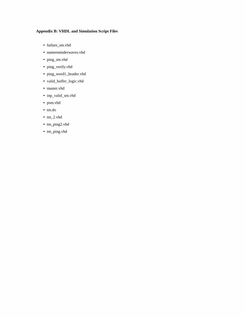
Appendix B: VHDL and Simulation Script Files
• failure_sm.vhd
• numreminderwaves.vhd
• ping_sm.vhd
• ping_verify.vhd
• ping_word1_header.vhd
• valid_buffer_logic.vhd
• master.vhd
• inp_valid_sm.vhd
• psm.vhd
• tm.do
• tm_2.vhd
• tm_ping2.vhd
• tm_ping.vhd

-- Christopher Batten-- [email protected]
-- Created for use in undergraduate thesis:-- "A Hardware Implementation for Component Failure Handling-- in Isotach Token Managers"
-- April 2, 1999
-- Failure State Machine-- Responsible for controlling the valid buffer and setting the-- set_errsig singal.
LIBRARY MGC_PORTABLE;USE MGC_PORTABLE.QSIM_LOGIC.ALL;
ENTITY failure_detect_sm ISPORT (clk : IN QSIM_STATE;
rst : IN QSIM_STATE;failure_detected : IN QSIM_STATE;validreset : OUT QSIM_STATE;clear_counter : OUT QSIM_STATE;set_errsig : OUT QSIM_STATE );
END failure_detect_sm;
ARCHITECTURE failure_detect_sm_arch OF failure_detect_sm ISTYPE failure_states IS (f0, f1, f2, f3, f4);SIGNAL state : failure_states;SIGNAL next_state : failure_states;
BEGIN
clocked: PROCESS (clk, rst)BEGIN
IF (rst = '1') THENstate <= f0;
ELSIF (clk'EVENT AND clk = '1') THENstate <= next_state;
END IF;END PROCESS clocked;
output: PROCESS (state)BEGIN
CASE state IS
-- Init stateWHEN f0 =>
validreset <= '1';clear_counter <= '1';set_errsig <= '0';
-- Idle stateWHEN f1 =>
validreset <= '0';clear_counter <= '0';set_errsig <= '0';

-- Failure has occuredWHEN f2 =>
validreset <= '0';clear_counter <= '1';set_errsig <= '1';
-- Hold set_errsig for 3 cyclesWHEN f3 =>
validreset <= '0';clear_counter <= '0';set_errsig <= '1';
-- Hold set_errsig for 3 cyclesWHEN f4 =>
validreset <= '0';clear_counter <= '0';set_errsig <= '1';
WHEN OTHERS =>validreset <= '0';clear_counter <= '0';set_errsig <= '0';
END CASE;END PROCESS output;
state_trans: PROCESS (state, failure_detected)BEGIN
CASE state IS
WHEN f0 =>next_state <= f1;
WHEN f1 =>IF (failure_detected = '1') THEN
next_state <= f2;ELSE
next_state <= f1;END IF;
WHEN f2 =>next_state <= f3;
WHEN f3 =>next_state <= f4;
WHEN f4 =>next_state <= f1;
WHEN OTHERS =>next_state <= f0;
END CASE;END PROCESS state_trans;
END failure_detect_sm_arch;

-- Christopher Batten-- [email protected]
-- Created for use in undergraduate thesis:-- "A Hardware Implementation for Component Failure Handling-- in Isotach Token Managers"
-- April 2, 1999
-- Hardcoded constant: the failure threshold-- (The number of reminder waves before a neighbor is declared dead)
LIBRARY MGC_PORTABLE;USE MGC_PORTABLE.QSIM_LOGIC.ALL;
ENTITY num_reminder_waves ISPORT (value : OUT QSIM_STATE_VECTOR(7 DOWNTO 0));
END num_reminder_waves;
ARCHITECTURE num_reminder_waves_arch OF num_reminder_waves ISBEGINvalue <= "00000010";
END num_reminder_waves_arch;

-- Christopher Batten-- [email protected]
-- Created for use in undergraduate thesis:-- "A Hardware Implementation for Component Failure Handling-- in Isotach Token Managers"
-- April 2, 1999
-- Ping handler state machine-- Responsible for moving return route information from buffers-- to the output FIFO bus.
LIBRARY MGC_PORTABLE;USE MGC_PORTABLE.QSIM_LOGIC.ALL;
ENTITY ping_handler_sm ISPORT (rst : IN QSIM_STATE;
clk : IN QSIM_STATE;ping_recv : IN QSIM_STATE;send_ping : IN QSIM_STATE;
fifo_ready : IN QSIM_STATE;ping_waiting : OUT QSIM_STATE;ping2fifo_sel : OUT QSIM_STATE;ping_word_sel : OUT QSIM_STATE;output_valid : OUT QSIM_STATE );
END ping_handler_sm;
ARCHITECTURE ping_handler_sm_arch OF ping_handler_sm ISTYPE ping_states IS (p0, p1, p2, p3, p4, p5);SIGNAL state : ping_states;SIGNAL next_state : ping_states;
BEGINoutput: PROCESS (state)BEGIN
CASE state ISWHEN p0 =>ping_waiting <= '0';ping2fifo_sel <= '0';ping_word_sel <= '0';output_valid <= '0';
WHEN p1 =>ping_waiting <= '1';ping2fifo_sel <= '0';ping_word_sel <= '0';output_valid <= '0';
WHEN p2 =>ping_waiting <= '1';ping2fifo_sel <= '1';ping_word_sel <= '0';output_valid <= '0';
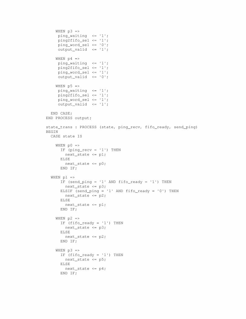
WHEN p3 =>ping_waiting <= '1';ping2fifo_sel <= '1';ping_word_sel <= '0';output_valid <= '1';
WHEN p4 =>ping_waiting <= '1';ping2fifo_sel <= '1';ping_word_sel <= '1';output_valid <= '0';
WHEN p5 =>ping_waiting <= '1';ping2fifo_sel <= '1';ping_word_sel <= '1';output_valid <= '1';
END CASE;END PROCESS output;
state_trans : PROCESS (state, ping_recv, fifo_ready, send_ping)BEGIN
CASE state IS
WHEN p0 =>IF (ping_recv = '1') THEN
next_state <= p1;ELSE
next_state <= p0;END IF;
WHEN p1 =>IF (send_ping = '1' AND fifo_ready = '1') THEN
next_state <= p3;ELSIF (send_ping = '1' AND fifo_ready = '0') THEN
next_state <= p2;ELSE
next_state <= p1;END IF;
WHEN p2 =>IF (fifo_ready = '1') THEN
next_state <= p3;ELSE
next_state <= p2;END IF;
WHEN p3 =>IF (fifo_ready = '1') THEN
next_state <= p5;ELSE
next_state <= p4;END IF;

WHEN p4 =>IF (fifo_ready = '1') THEN
next_state <= p5;ELSE
next_state <= p4;END IF;
WHEN p5 =>next_state <= p0;
END CASE;END PROCESS state_trans;
clocked: PROCESS (clk, rst)BEGIN
IF (rst = '1') THENstate <= p0;
ELSIF (clk'EVENT AND clk = '1') THENstate <= next_state;
END IF;END PROCESS clocked;
END ping_handler_sm_arch;

-- Christopher Batten-- [email protected]
-- Modified/Created for use in undergraduate thesis:-- "A Hardware Implementation for Component Failure Handling-- in Isotach Token Managers"
-- April 2, 1999
-- Ping verifier: Checks first 19 bits of an incomming word to-- see if it matches the isotach message type identifier.
LIBRARY MGC_PORTABLE;USE MGC_PORTABLE.QSIM_LOGIC.ALL;
ENTITY ping_verifier ISPORT (msg_type : IN QSIM_STATE_VECTOR(18 DOWNTO 0);
ping_valid : OUT QSIM_STATE);END ping_verifier;
ARCHITECTURE ping_verifier_arch OF ping_verifier ISBEGINPROCESS (msg_type)BEGIN
IF (msg_type = "0000000011000000000") THENping_valid <= '1';
ELSEping_valid <= '0';
END IF;END PROCESS;
END ping_verifier_arch;

-- Christopher Batten-- [email protected]
-- Modified/Created for use in undergraduate thesis:-- "A Hardware Implementation for Component Failure Handling-- in Isotach Token Managers"
-- April 2, 1999
-- Header for the first word of the ping return route:-- The first word will always be two bytes long and thus we will-- need to prepend two bytes of zeros. Additionally, we need to set-- the FI control signals to indicate that only the last two bytes-- have useful information. According to FI docs this requires-- the control signals 010 to begin the first word.
LIBRARY MGC_PORTABLE;USE MGC_PORTABLE.QSIM_LOGIC.ALL;
ENTITY ping_word1_head ISPORT (ping_word1_header: OUT QSIM_STATE_VECTOR(18 DOWNTO 0));
END ping_word1_head;
ARCHITECTURE ping_word1_head_arch OF ping_word1_head ISBEGINping_word1_header <= "0100000000000000000";
END ping_word1_head_arch;

-- Christopher Batten-- [email protected]
-- Modified/Created for use in undergraduate thesis:-- "A Hardware Implementation for Component Failure Handling-- in Isotach Token Managers"
-- April 2, 1999
-- Valid buffer logic: Combinational block that sets the-- valid bits. Allows these bits to be intialized by the-- initialval and determines if the valid bit should be set-- to zero based on sendauth.
LIBRARY MGC_PORTABLE;USE MGC_PORTABLE.QSIM_LOGIC.ALL;
ENTITY valid_buf_logic ISPORT (laststored : IN QSIM_STATE;
sendauth : IN QSIM_STATE;initialval : IN QSIM_STATE;reset : IN QSIM_STATE;newvalue : OUT QSIM_STATE);
END valid_buf_logic;
ARCHITECTURE valid_buf_logic_arch OF valid_buf_logic ISBEGINPROCESS ( laststored, sendauth, initialval, reset )BEGINif ( reset = '1' ) then
newvalue <= initialval;else
newvalue <= sendauth AND laststored;end if;
END PROCESS;END valid_buf_logic_arch;

-- Token Manager Control Unit: Master State Machine-- Orginally written by Brian Kuebert-- Modified by Chris Batten (4/2/99) to add a new state-- for handling host-to-TM pings
LIBRARY MGC_PORTABLE;USE MGC_PORTABLE.QSIM_LOGIC.ALL;
ENTITY master ISPORT (ok_to_send : IN QSIM_STATE;
timeout : IN QSIM_STATE;send_auth : IN QSIM_STATE_VECTOR(14 DOWNTO 0);rst : IN QSIM_STATE;clk : IN QSIM_STATE;W : IN QSIM_STATE_VECTOR(1 DOWNTO 0);
rec_sig_6 : IN QSIM_STATE;
-- New signal indicates return route info is ready-- to be move to the output FIFO [CFB 4/2/99]ping_waiting : IN QSIM_STATE;
sent : OUT QSIM_STATE;TS_to_send : OUT QSIM_STATE_VECTOR(1 DOWNTO 0);send_now : OUT QSIM_STATE;incW : OUT QSIM_STATE;timeout_reset : OUT QSIM_STATE;reminder : OUT QSIM_STATE;
-- New signal indicates that the MSM is paused so-- the PHSM may move the return route info to the-- output FIFO [CFB 4/2/99]send_ping : OUT QSIM_STATE;
master_state : OUT QSIM_STATE_VECTOR(2 DOWNTO 0));END master;
ARCHITECTURE master_arch OF master ISSIGNAL state : QSIM_STATE_VECTOR(3 DOWNTO 0);SIGNAL next_state : QSIM_STATE_VECTOR(3 DOWNTO 0);
BEGIN
-- In order not to modify the output pins only the low 3 bits-- of the state vector are sent to output [CFB]master_state <= state(2 downto 0);
output: PROCESS (state, W)BEGIN
CASE state ISWHEN "0000" => sent <= '0'; -- state m0
TS_to_send <= "XX";send_now <= '0';incW <= '0';timeout_reset <= '0';reminder <= '0';send_ping <= '0';

WHEN "0001" => sent <= '0'; -- state m1CASE W IS
WHEN "00" => TS_to_send <= "00";WHEN "01" => TS_to_send <= "01";WHEN "10" => TS_to_send <= "10";WHEN "11" => TS_to_send <= "11";WHEN OTHERS => TS_to_send <= "XX";
END CASE;send_now <= '1';incW <= '0';timeout_reset <= '0';reminder <= '0';send_ping <= '0';
WHEN "0010" => sent <= '0'; -- state m2CASE W IS
WHEN "00" => TS_to_send <= "00";WHEN "01" => TS_to_send <= "01";WHEN "10" => TS_to_send <= "10";WHEN "11" => TS_to_send <= "11";WHEN OTHERS => TS_to_send <= "XX";
END CASE;send_now <= '0';incW <= '0';timeout_reset <= '0';reminder <= '0';send_ping <= '0';
WHEN "0011" => sent <= '1'; -- state m3TS_to_send <= "XX";send_now <= '0';incW <= '1';timeout_reset <= '1';reminder <= '0';send_ping <= '0';
WHEN "0100" => sent <= '0'; -- state m4CASE W IS
WHEN "00" => TS_to_send <= "10";WHEN "01" => TS_to_send <= "11";WHEN "10" => TS_to_send <= "00";WHEN "11" => TS_to_send <= "01";WHEN OTHERS => TS_to_send <= "XX";
END CASE;send_now <= '1';incW <= '0';timeout_reset <= '0';reminder <= '1';send_ping <= '0';

WHEN "0101" => sent <= '0'; -- state m5CASE W IS
WHEN "00" => TS_to_send <= "10";WHEN "01" => TS_to_send <= "11";WHEN "10" => TS_to_send <= "00";WHEN "11" => TS_to_send <= "01";WHEN OTHERS => TS_to_send <= "XX";
END CASE;send_now <= '0';incW <= '0';timeout_reset <= '0';reminder <= '1';send_ping <= '0';
WHEN "0110" => sent <= '0'; -- state m6CASE W IS
WHEN "00" => TS_to_send <= "11";WHEN "01" => TS_to_send <= "00";WHEN "10" => TS_to_send <= "01";WHEN "11" => TS_to_send <= "10";WHEN OTHERS => TS_to_send <= "XX";
END CASE;send_now <= '1';incW <= '0';timeout_reset <= '1';reminder <= '1';send_ping <= '0';
WHEN "0111" => sent <= '0'; -- state m7CASE W IS
WHEN "00" => TS_to_send <= "11";WHEN "01" => TS_to_send <= "00";WHEN "10" => TS_to_send <= "01";WHEN "11" => TS_to_send <= "10";WHEN OTHERS => TS_to_send <= "XX";
END CASE;send_now <= '0';incW <= '0';timeout_reset <= '0';reminder <= '1';send_ping <= '0';
-- New state for waiting until a ping has finishedWHEN "1000" => sent <= '0'; -- state m8
TS_to_send <= "XX";send_now <= '0';incW <= '0';timeout_reset <= '0';reminder <= '0';send_ping <= '1';

WHEN OTHERS => sent <= 'X';TS_to_send <= "XX";send_now <= 'X';incW <= 'X';timeout_reset <= 'X';reminder <= 'X';send_ping <= 'X';
END CASE;END PROCESS output;
state_trans : PROCESS (ok_to_send, timeout, send_auth, state,rec_sig_6, ping_waiting)
BEGINCASE state IS
WHEN "0000" => -- state m0IF ((ok_to_send = '1' AND send_auth = "111111111111111")
OR (rec_sig_6 = '1')) THENnext_state <= "0001"; --M1
ELSIF (ok_to_send = '1' AND timeout = '1') THENnext_state <= "0100"; --M4
ELSIF (ping_waiting = '1') THENnext_state <= "1000";
ELSEnext_state <= "0000"; --M0
END IF;
WHEN "0001" => -- state m1next_state <= "0010"; --M2
WHEN "0010" => -- state m2IF (ok_to_send = '1') THEN
next_state <= "0011"; --M3ELSE
next_state <= "0010"; --M2END IF;
WHEN "0011" => -- state m3next_state <= "0000"; --M0
WHEN "0100" => -- state m4next_state <= "0101"; --M5
WHEN "0101" => -- state m5IF (ok_to_send = '1') THEN
next_state <= "0110"; --M6ELSE
next_state <= "0101"; --M5END IF;
WHEN "0110" => -- state m6next_state <= "0111"; --M7

WHEN "0111" => -- state m7IF (ok_to_send = '1') THEN
next_state <= "0000"; --M0ELSE
next_state <= "0111"; --M7END IF;
-- Wait in state m8 until finished sending pingWHEN "1000" => -- state m8
IF (ping_waiting = '0') THENnext_state <= "0000";
ELSEnext_state <= "1000";
END IF;
WHEN OTHERS =>next_state <= "0000";
END CASE;END PROCESS state_trans;
clocked: PROCESS (clk, rst)BEGIN
IF (rst = '1') THENstate <= "0000";
ELSIF (clk'EVENT AND clk = '1') THENstate <= next_state;
END IF;END PROCESS clocked;
END master_arch;

-- Brian D. Kuebert-- modified 8/04/98 by AWS to bring out state bit - add in_valid input-- modified 3/15/99 by CFB to add additional state for host-to-TM-- ping handling
LIBRARY MGC_PORTABLE;USE MGC_PORTABLE.QSIM_LOGIC.ALL;
ENTITY inp_valid_sm ISPORT (clk : IN QSIM_STATE;
rst : IN QSIM_STATE;buff_en : IN QSIM_STATE;verify : IN QSIM_STATE;ping_valid : IN QSIM_STATE;in_valid : IN QSIM_STATE;ping_recv : OUT QSIM_STATE;inp_valid_state : OUT QSIM_STATE;inp_valid : OUT QSIM_STATE);
END inp_valid_sm;
ARCHITECTURE inp_valid_sm_arch OF inp_valid_sm ISSIGNAL state : QSIM_STATE_VECTOR( 1 downto 0 );SIGNAL next_state: QSIM_STATE_VECTOR( 1 downto 0 );
BEGINclocked: PROCESS (clk, rst)BEGIN
IF (rst = '1') THENstate <= "00";
ELSIF (clk'EVENT AND clk = '1') THENstate <= next_state;
-- In order to avoid modifying the output pins, we do not-- use two pins to output the inp_valid_state. [CFB 3/15/99]inp_valid_state <= next_state(0);
END IF;END PROCESS clocked;
output: PROCESS (state, verify)BEGIN
CASE state IS
WHEN "00" =>ping_recv <= '0';inp_valid <= '0';
WHEN "01" =>ping_recv <= '0';IF (verify = '1') THEN
inp_valid <= '1';ELSE
inp_valid <= '0';END IF;

-- New state to handle host-to-TM pings [CFB 4/2/99]WHEN "11" =>
ping_recv <= '1';inp_valid <= '0';
WHEN OTHERS =>ping_recv <= 'X';inp_valid <= 'X';
END CASE;END PROCESS output;
state_trans: PROCESS (state, buff_en, in_valid, ping_valid)BEGIN
CASE state IS
WHEN "00" =>IF (buff_en = '1') THEN
next_state <= "01";ELSIF (ping_valid = '1') THEN
next_state <= "11";ELSE
next_state <= "00";END IF;
WHEN "01" =>IF (in_valid = '1') THEN
next_state <= "00";ELSE
next_state <= "01";END IF;
WHEN "11" =>IF (in_valid = '1') THEN
next_state <= "00";ELSE
next_state <= "11";END IF;
WHEN OTHERS =>next_state <= "00";
END CASE;END PROCESS state_trans;
END inp_valid_sm_arch;

-- Token Manager Control Unit: Port State Machine-- Created by Brian Kuebert-- Modified by Chris Batten [4/2/99]-- Added faildetect signal to allow the failure state machine-- to push a PSM into state s1.
LIBRARY MGC_PORTABLE;USE MGC_PORTABLE.QSIM_LOGIC.ALL;
ENTITY psm ISPORT (rst : IN QSIM_STATE;
clk : IN QSIM_STATE;sent : IN QSIM_STATE;got00 : IN QSIM_STATE;got01 : IN QSIM_STATE;got10 : IN QSIM_STATE;got11 : IN QSIM_STATE;
-- New signal that is high when failure has been detected [CFB]faildetect : IN QSIM_STATE;
W : IN QSIM_STATE_VECTOR(1 DOWNTO 0);send_auth : OUT QSIM_STATE);
END psm;
ARCHITECTURE psm_arch OF psm ISTYPE psm_states IS (s0, s1);SIGNAL state : psm_states;SIGNAL next_state : psm_states;
BEGIN
output: PROCESS (state)BEGIN
CASE state ISWHEN s0 => send_auth <= '1';WHEN s1 => send_auth <= '0';
END CASE;END PROCESS output;
state_trans : PROCESS (sent, got00, got01, got10, got11, state,faildetect, W)
BEGINCASE state IS
WHEN s0 =>IF (sent = '1') THENnext_state <= s1;
ELSEnext_state <= s0;
END IF;

WHEN s1 =>
-- if failure detected move back into ready stateIF ( faildetect = '1' ) THENnext_state <= s0;
ELSE
IF (W = "00" AND got11 = '1') THENnext_state <= s0;
ELSIF (W = "01" AND got00 = '1') THENnext_state <= s0;
ELSIF (W = "10" AND got01 = '1') THENnext_state <= s0;
ELSIF (W = "11" AND got10 = '1') THENnext_state <= s0;
ELSE next_state <= s1;
END IF;
END IF;END CASE;
END PROCESS state_trans;
clocked: PROCESS (clk, rst)BEGIN
IF (rst = '1') THENstate <= s0;
ELSIF (clk'EVENT AND clk = '1') THENstate <= next_state;
END IF;END PROCESS clocked;
END psm_arch;
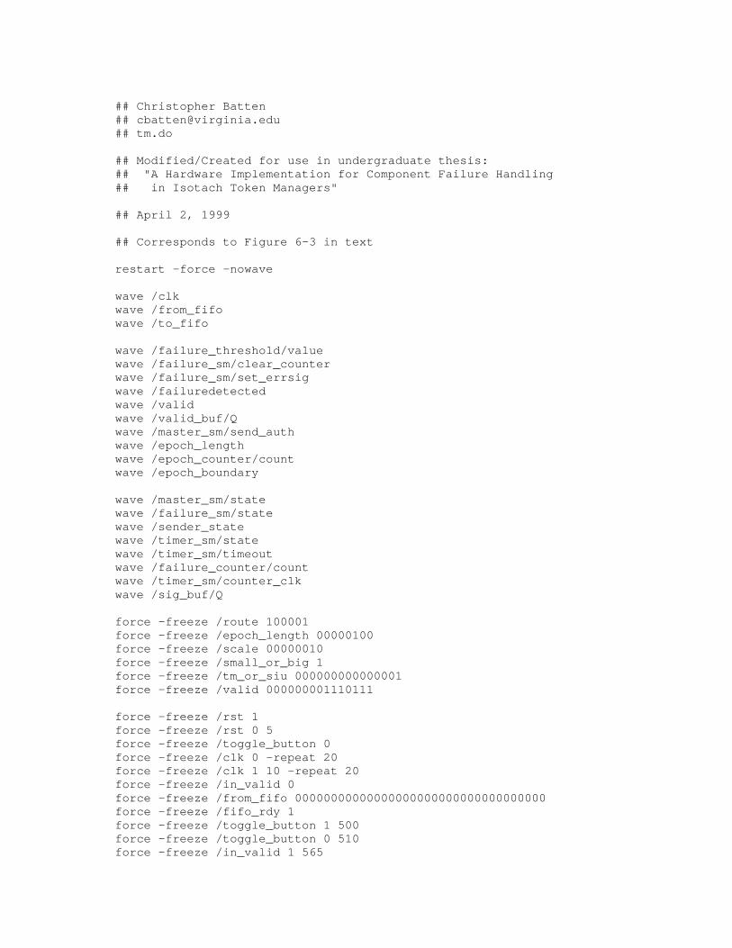
## Christopher Batten## [email protected]## tm.do
## Modified/Created for use in undergraduate thesis:## "A Hardware Implementation for Component Failure Handling## in Isotach Token Managers"
## April 2, 1999
## Corresponds to Figure 6-3 in text
restart -force -nowave
wave /clkwave /from_fifowave /to_fifo
wave /failure_threshold/valuewave /failure_sm/clear_counterwave /failure_sm/set_errsigwave /failuredetectedwave /validwave /valid_buf/Qwave /master_sm/send_authwave /epoch_lengthwave /epoch_counter/countwave /epoch_boundary
wave /master_sm/statewave /failure_sm/statewave /sender_statewave /timer_sm/statewave /timer_sm/timeoutwave /failure_counter/countwave /timer_sm/counter_clkwave /sig_buf/Q
force -freeze /route 100001force -freeze /epoch_length 00000100force -freeze /scale 00000010force -freeze /small_or_big 1force -freeze /tm_or_siu 000000000000001force -freeze /valid 000000001110111
force -freeze /rst 1force -freeze /rst 0 5force -freeze /toggle_button 0force -freeze /clk 0 -repeat 20force -freeze /clk 1 10 -repeat 20force -freeze /in_valid 0force -freeze /from_fifo 00000000000000000000000000000000000force -freeze /fifo_rdy 1force -freeze /toggle_button 1 500force -freeze /toggle_button 0 510force -freeze /in_valid 1 565

## Send token wave - missing one token ...
# | | | | ##123456| |force -freeze /from_fifo 00000000110000000010000000100000000 565force -freeze /from_fifo 11100000000000000000000000000000000 585
force -freeze /from_fifo 00000000110000000010000001000000000 605force -freeze /from_fifo 11100000000000000000000000000000000 625
force -freeze /from_fifo 00000000110000000010000010100000000 645force -freeze /from_fifo 11100000000000000000000000000000000 665
force -freeze /from_fifo 00000000110000000010000011000000000 685force -freeze /from_fifo 11100000000000000000000000000000000 705
force -freeze /from_fifo 00000000110000000010000011100000000 725force -freeze /from_fifo 11100000000000000000000000000000000 745
## Another wave ...
force -freeze /from_fifo 00000000110000000010100000100000000 81944force -freeze /from_fifo 11100000000000000000000000000000000 81964
force -freeze /from_fifo 00000000110000000010100001000000000 81984force -freeze /from_fifo 11100000000000000000000000000000000 82004
# This token has err_clr signal setforce -freeze /from_fifo 00000000110000000010100010100100000 82024force -freeze /from_fifo 11100000000000000000000000000000000 82044
force -freeze /from_fifo 00000000110000000010100011000000000 82064force -freeze /from_fifo 11100000000000000000000000000000000 82084
force -freeze /from_fifo 00000000110000000010100011100000000 82104force -freeze /from_fifo 11100000000000000000000000000000000 82124
## One more wave to let the epoch run out ...force -freeze /from_fifo 00000000110000000011000000100000000 100944force -freeze /from_fifo 11100000000000000000000000000000000 100964
force -freeze /from_fifo 00000000110000000011000001000000000 100984force -freeze /from_fifo 11100000000000000000000000000000000 101004
force -freeze /from_fifo 00000000110000000011000010100000000 101024force -freeze /from_fifo 11100000000000000000000000000000000 101044
force -freeze /from_fifo 00000000110000000011000011000000000 101064force -freeze /from_fifo 11100000000000000000000000000000000 101084
force -freeze /from_fifo 00000000110000000011000011100000000 101104force -freeze /from_fifo 11100000000000000000000000000000000 101124
## And finally one more wave to see the err_clr resetforce -freeze /from_fifo 00000000110000000011100000100000000 120944force -freeze /from_fifo 11100000000000000000000000000000000 120964

force -freeze /from_fifo 00000000110000000011100001000000000 120984force -freeze /from_fifo 11100000000000000000000000000000000 121004
force -freeze /from_fifo 00000000110000000011100010100000000 121024force -freeze /from_fifo 11100000000000000000000000000000000 121044
force -freeze /from_fifo 00000000110000000011100011000000000 121064force -freeze /from_fifo 11100000000000000000000000000000000 121084
force -freeze /from_fifo 00000000110000000011100011100000000 121104force -freeze /from_fifo 11100000000000000000000000000000000 121124
run 140000

## Christopher Batten## [email protected]## tm_2.do
## Modified/Created for use in undergraduate thesis:## "A Hardware Implementation for Component Failure Handling## in Isotach Token Managers"
## April 2, 1999
## Corresponds to Figure 6-5 in text
restart -force -nowave
wave /clkwave /from_fifowave /to_fifo
wave /failure_threshold/valuewave /failure_sm/clear_counterwave /failure_sm/set_errsigwave /failuredetectedwave /validwave /valid_buf/Qwave /master_sm/send_authwave /epoch_lengthwave /epoch_counter/countwave /epoch_boundary
wave /master_sm/statewave /failure_sm/statewave /sender_statewave /timer_sm/statewave /timer_sm/timeoutwave /failure_counter/countwave /timer_sm/counter_clkwave /sig_buf/Q
force -freeze /route 100001force -freeze /epoch_length 00000011force -freeze /scale 00000010force -freeze /small_or_big 1force -freeze /tm_or_siu 000000000000001force -freeze /valid 000000001110111
force -freeze /rst 1force -freeze /rst 0 5force -freeze /toggle_button 0force -freeze /clk 0 -repeat 20force -freeze /clk 1 10 -repeat 20force -freeze /in_valid 0force -freeze /from_fifo 00000000000000000000000000000000000force -freeze /fifo_rdy 1force -freeze /toggle_button 1 500force -freeze /toggle_button 0 510force -freeze /in_valid 1 565
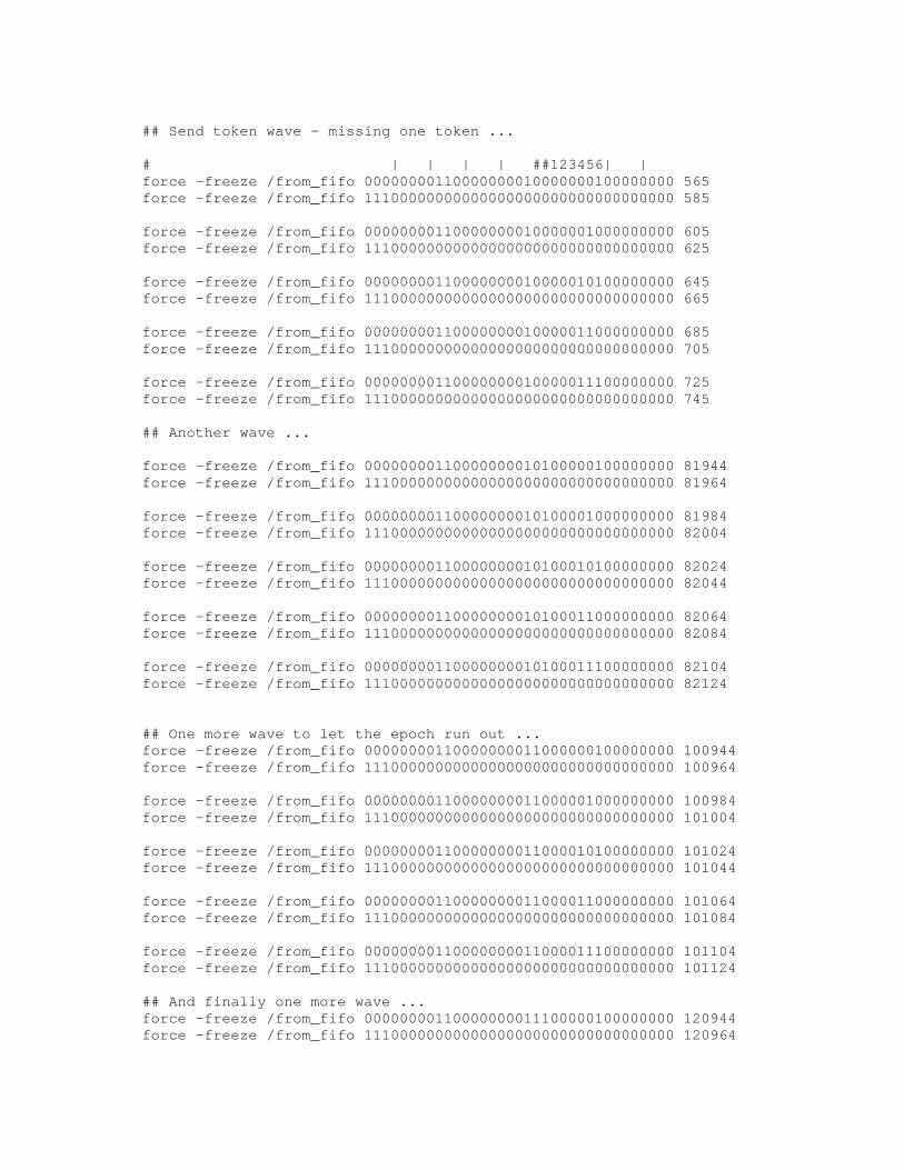
## Send token wave - missing one token ...
# | | | | ##123456| |force -freeze /from_fifo 00000000110000000010000000100000000 565force -freeze /from_fifo 11100000000000000000000000000000000 585
force -freeze /from_fifo 00000000110000000010000001000000000 605force -freeze /from_fifo 11100000000000000000000000000000000 625
force -freeze /from_fifo 00000000110000000010000010100000000 645force -freeze /from_fifo 11100000000000000000000000000000000 665
force -freeze /from_fifo 00000000110000000010000011000000000 685force -freeze /from_fifo 11100000000000000000000000000000000 705
force -freeze /from_fifo 00000000110000000010000011100000000 725force -freeze /from_fifo 11100000000000000000000000000000000 745
## Another wave ...
force -freeze /from_fifo 00000000110000000010100000100000000 81944force -freeze /from_fifo 11100000000000000000000000000000000 81964
force -freeze /from_fifo 00000000110000000010100001000000000 81984force -freeze /from_fifo 11100000000000000000000000000000000 82004
force -freeze /from_fifo 00000000110000000010100010100000000 82024force -freeze /from_fifo 11100000000000000000000000000000000 82044
force -freeze /from_fifo 00000000110000000010100011000000000 82064force -freeze /from_fifo 11100000000000000000000000000000000 82084
force -freeze /from_fifo 00000000110000000010100011100000000 82104force -freeze /from_fifo 11100000000000000000000000000000000 82124
## One more wave to let the epoch run out ...force -freeze /from_fifo 00000000110000000011000000100000000 100944force -freeze /from_fifo 11100000000000000000000000000000000 100964
force -freeze /from_fifo 00000000110000000011000001000000000 100984force -freeze /from_fifo 11100000000000000000000000000000000 101004
force -freeze /from_fifo 00000000110000000011000010100000000 101024force -freeze /from_fifo 11100000000000000000000000000000000 101044
force -freeze /from_fifo 00000000110000000011000011000000000 101064force -freeze /from_fifo 11100000000000000000000000000000000 101084
force -freeze /from_fifo 00000000110000000011000011100000000 101104force -freeze /from_fifo 11100000000000000000000000000000000 101124
## And finally one more wave ...force -freeze /from_fifo 00000000110000000011100000100000000 120944force -freeze /from_fifo 11100000000000000000000000000000000 120964

force -freeze /from_fifo 00000000110000000011100001000000000 120984force -freeze /from_fifo 11100000000000000000000000000000000 121004
force -freeze /from_fifo 00000000110000000011100010100000000 121024force -freeze /from_fifo 11100000000000000000000000000000000 121044
force -freeze /from_fifo 00000000110000000011100011000000000 121064force -freeze /from_fifo 11100000000000000000000000000000000 121084
force -freeze /from_fifo 00000000110000000011100011100000000 121104force -freeze /from_fifo 11100000000000000000000000000000000 121124
run 140000

## Christopher Batten## [email protected]## tm_ping2.do
## Modified/Created for use in undergraduate thesis:## "A Hardware Implementation for Component Failure Handling## in Isotach Token Managers"
## April 2, 1999
## Corresponds to Figure 6-6 in text
restart -force -nowave
wave /clkwave /rstwave /fifo_rdywave /output_validwave /to_fifowave /in_validwave /from_fifo
## State Machineswave /master_sm/statewave /sender_statewave /inp_valid_sm/statewave /ping_sm/state
## Ping variableswave /ping_verifier/ping_validwave /master_sm/send_pingwave /ping_sm/ping_waitingwave /ping_sm/ping_word_selwave /ping_sm/ping2fifo_sel
## Return route buffer outputswave /return_route_word1/Qwave /return_route_word2/Q
force -freeze /route 100001force -freeze /epoch_length 11111111force -freeze /scale 00000010force -freeze /small_or_big 1force -freeze /tm_or_siu 000000000000001force -freeze /valid 000000001110111
force -freeze /rst 1force -freeze /rst 0 5force -freeze /toggle_button 0force -freeze /clk 0 -repeat 20force -freeze /clk 1 10 -repeat 20force -freeze /in_valid 0force -freeze /from_fifo 00000000000000000000000000000000000force -freeze /fifo_rdy 1
force -freeze /toggle_button 1 500

force -freeze /toggle_button 0 510force -freeze /in_valid 1 565
## Host-to-TM ping# FI -- PingTypeID --# | | | | | | | |force -freeze /from_fifo 00000000110000000000110011001100110 600force -freeze /from_fifo 00001100110011001100110011001100110 620
run 1000

## Christopher Batten## [email protected]## tm_ping.do
## Modified/Created for use in undergraduate thesis:## "A Hardware Implementation for Component Failure Handling## in Isotach Token Managers"
## April 2, 1999
## Corresponds to Figure 6-7 in text
restart -force -nowave
wave /clkwave /rstwave /fifo_rdywave /output_validwave /to_fifowave /in_validwave /from_fifo
## State Machineswave /master_sm/statewave /sender_statewave /inp_valid_sm/statewave /ping_sm/state
## Ping variableswave /ping_verifier/ping_validwave /master_sm/send_pingwave /ping_sm/ping_waitingwave /ping_sm/ping_word_selwave /ping_sm/ping2fifo_sel
## Return route buffer outputswave /return_route_word1/Qwave /return_route_word2/Q
force -freeze /route 100001force -freeze /epoch_length 11111111force -freeze /scale 00000010force -freeze /small_or_big 1force -freeze /tm_or_siu 000000000000001force -freeze /valid 000000001110111
force -freeze /rst 1force -freeze /rst 0 5force -freeze /toggle_button 0force -freeze /clk 0 -repeat 20force -freeze /clk 1 10 -repeat 20force -freeze /in_valid 0force -freeze /from_fifo 00000000000000000000000000000000000force -freeze /fifo_rdy 1
force -freeze /toggle_button 1 500

force -freeze /toggle_button 0 510force -freeze /in_valid 1 565
## Normal token wave# | | | | ##123456| |force -freeze /from_fifo 00000000110000000010000000100000000 565force -freeze /from_fifo 11100000000000000000000000000000000 585
force -freeze /from_fifo 00000000110000000010000001000000000 605force -freeze /from_fifo 11100000000000000000000000000000000 625
force -freeze /from_fifo 00000000110000000010000010100000000 645force -freeze /from_fifo 11100000000000000000000000000000000 665
force -freeze /from_fifo 00000000110000000010000011000000000 685force -freeze /from_fifo 11100000000000000000000000000000000 705
force -freeze /from_fifo 00000000110000000010000011100000000 725force -freeze /from_fifo 11100000000000000000000000000000000 745
force -freeze /from_fifo 00000000110000000010000001100000000 765force -freeze /from_fifo 11100000000000000000000000000000000 785
## Host-to-TM ping# FI -- PingTypeID --# | | | | | | | |force -freeze /from_fifo 00000000110000000000110011001100110 1000force -freeze /from_fifo 00001100110011001100110011001100110 1020
run 2000


![Diameter Failure Handling Template Configuration Mode … · update-location-request|user-data-request}failure-type{any|diabase-error|diameterresult-code {any-error|result-code[toend-result-code]}|diameterexp-result-code{any-error|result-code[to](https://static.fdocuments.in/doc/165x107/5fd9a5e0192677666b125226/diameter-failure-handling-template-configuration-mode-update-location-requestuser-data-requestfailure-typeanydiabase-errordiameterresult-code.jpg)