
A Few Words First - INCOSE
40
1 A Few Words First Courtesy – Please mute your phone (*6 toggle). Upcoming Chapter Meetings: • May 10, Developing the Next Generation of Systems Engineering Leaders Dawn Schaible, NASA Deputy Chief Engineer • May 19 Tutorial, Agile Risk Management Rick Dove, Paradigm Shift International Registration is Open – www.incose.org/enchantment in Library/Tutorials • Jun 14, Defining “System” – a Comprehensive Approach Regina Griego, Sandia National Labs • Jul ??, Summer Social, TBD Aug 21-25, International Systems Safety Conference, Albuquerque, NM http://issc2017.system-safety.org Oct 06-07, 2017 Socorro Systems Summit at NM Tech CSEP Courses by Certification Training International: Course details | Course brochure 2017 Course Schedule (close by, but many more locations and dates): May 1-5 | Denver, CO Aug 7-11 | Austin, TX Oct 30-Nov 3 | Las Vegas, NV And Now - Introductions First slide, not recorded but retained in pdf presentation.
Transcript of A Few Words First - INCOSE

1
A Few Words FirstCourtesy – Please mute your phone (*6 toggle).Upcoming Chapter Meetings:• May 10, Developing the Next Generation of Systems Engineering Leaders
Dawn Schaible, NASA Deputy Chief Engineer • May 19 Tutorial, Agile Risk Management
Rick Dove, Paradigm Shift InternationalRegistration is Open – www.incose.org/enchantment in Library/Tutorials
• Jun 14, Defining “System” – a Comprehensive ApproachRegina Griego, Sandia National Labs
• Jul ??, Summer Social, TBDAug 21-25, International Systems Safety Conference, Albuquerque, NM
http://issc2017.system-safety.orgOct 06-07, 2017 Socorro Systems Summit at NM Tech
CSEP Courses by Certification Training International:Course details | Course brochure2017 Course Schedule (close by, but many more locations and dates):May 1-5 | Denver, COAug 7-11 | Austin, TXOct 30-Nov 3 | Las Vegas, NV
And Now - IntroductionsFirst slide, not recorded but retained in pdf presentation.

2
12 April 2017 – 11:45am-1:00 pm: What the Systems Community Can Learn from ASME Work in Computational Model V&V Standardization
Bill Schindel, President, ICTT System Sciences, [email protected]: ASME teams are pioneering the generation of guidelines and standards concerning verification and validation of computational models and modeling, helping the related practitioner communities establish a shared view of this important and advancing practice. The INCOSE sister engineering society for general systems illustrates the interest of the systems community in this advance, attracting contributions to the effort, and learning from it. INCOSE has seen explosive growth in generation and use of general system models across many domains, including aerospace, automotive, medical and health care, advanced manufacturing, and infrastructure systems. As these models are consulted for managing risks and opportunities and making decisions that include safety-critical and large financial issues, questions of trust in the models themselves rapidly become critical. In the systems community, those questions are only part of the rapidly evolving context, which also includes the rise of standards-based systems modeling languages, advanced modeling tools, and integrated executable models and simulations as a part of the overall systems model fabric. The ASME efforts in model V&V, although originally targeting a narrower class of models, is surfacing and describing many principles of model V&V that can also be made to apply to more general classes of system models. This talk reflects the perspective of INCOSE Model-Based Systems Engineering community leadership, concerning the need for V&Vof systems models in general, and the opportunity to learn from and contribute to the related ASMEstandards committee efforts.
Enchantment ChapterMonthly Meeting
NOTE: This meeting will be recordedDownload slides today-only from GlobalMeetSeven file library or
anytime from the Library at www.incose.org/enchantment

3
Today’s Presentation
Things to Think About
How can this be applied in your work environment?What did you hear that will influence your thinking?
What is your take away from this presentation?

4
Speaker BioWilliam D. (Bill) Schindel chairs the Model-Based Systems Engineering Patterns Working Group of the INCOSE/OMG MBSE Initiative.An ASME member, he is part of the ASME VV50 standards team’s effort to describe the verification and validation of targeted models. Schindel is president of ICTT System Sciences, and has practiced systems engineering for over thirty years, across multiple industry domains.
He earned the B.S. and M.S. degrees in mathematics, is an INCOSE Fellow, and an INCOSE Certified Systems Engineering Professional.

5
What the Systems Community Can Learn from ASME Work in
Computational Model V&V Standardization
Model Verification, Validation, and Uncertainty Quantification
Bill Schindel, ICTT System [email protected]
1.3.2

6
8
System of Interest
Describes Some Aspect of Model
Do the System Requirements describe what stakeholders need?
Does the System Design define a solution meeting the System Requirements?
Does the Model adequately describe what it is intended to describe?
Does the Model implementation adequately represent what the Model says?
V&V of Models, Per Emerging ASME Model V&V Standards
V&V of Systems, Per ISO 15288 & INCOSE Handbook
Model Verification
Model Validation
System Verification
System Validation
Requirements validated?
Design verified?
Model validated?
Model verified?
Don’t forget: A model (on the left) may be used for system verification or validation (on the right!)
6The idea in a nutshell . . .

7
Contents• Models: Enthusiasm, purpose, trust• Kinds of models• V&V of systems vs. V&V of models• Scientific heritage• Related ASME activities and resources• Modeling the model situation and life cycle• Maturity in use of models• Community activities• What you can do
• References

8
Model enthusiasm
The INCOSE systems community has shown growing enthusiasm for “engineering with models” of all sorts:
– Historical tradition of math-physics engineering models– A World in Motion: INCOSE Vision 2025– Growth of the INCOSE IW MBSE Workshop– Growth in systems engineers in modeling classes – INCOSE Board of Directors’ objective to accelerate
transformation of SE to a model-based discipline– Joint INCOSE activities with NAFEMS

9
Models for what purposes?
Potentially for any ISO 15288 processes:• If there is a net
benefit . . .• Some more obvious
than others.• The INCOSE MBE
Transformation is using ISO 15288 framework as an aid to migration planning and assessment.

10
If we expect to use models to support critical decisions, then we are placing increased trust in models:
– Critical financial, other business decisions– Human life safety– Societal impacts – Extending human capability
• This talk is about efforts to characterize the structure of that trust (confidence in models) and manage it:– The Validation, Verification, and Uncertainty Quantification
(VVUQ) of the models themselves.

11
Kinds of models
From: Huanga, Zhanga, Dinga, “An analytical model of residual stress for flank milling of Ti-6Al-4V”, 15th CIRP Conference on Modelling of Machining Operations

12
Kinds of modelsFor purposes of this talk, by “Model” we mean an explicit data structure that effectively describes, to a Model Interpreter, aspects of a Modeled Thing useful for the purposes of engineering or science:

13
Kinds of modelsEven within that restricted notion of “Model”, current engineering practice may include an evolving mix of different kinds of models, known by differing names, sometimes for the same thing, sometimes for the same things:
• “System models”, “MBSE models”• “Physics-based models”• “Data-driven models”• “Executable” or “Computational” models (simulations)• Other types or other names for the same types
• Two above refer in part to how the models are developed . . .

14
Physics-Based Model Data Driven Model
System
System Component
External“Actors”
Real Target System Being Modeled
• Predicts the external behavior of the System of Interest, visible externally to the external actors with which it interacts.
• Models internal physical interactions of the System of Interest, and how they combine to cause/explain externally visible behavior.
• Model has both external predictive value and phenomena-based internal-to-external explanatory value.
• Overall model may have high dimensionality.
• Predicts the external behavior of the System of Interest, visible to the external actors with which it interacts.
• Model intermediate quantities may not correspond to internal or external physical parameters, but combine to adequately predict external behavior, fitting it to compressed relationships.
• Model has external predictive value, but not internal explanatory value.
• Overall model may have reduced dimensionality.
optional
predictspredicts, explains
• Data scientists and their math/IT tools can apply here (data mining, pattern extraction, cognitive AI tooling).
• Tools and methods for discovery / extraction of recurring patterns of external behavior.
From: Huanga, Zhanga, Dinga, “An analytical model of residual stress for flank milling of Ti-6Al-4V”, 15th CIRP Conference on Modelling of Machining Operations
• Physical scientists and phenomena models from their disciplines can apply here.
• The hard sciences physical laws, and how they can be used to explain the externally visible behavior of the system of interest.
Residual Stress for Milling Process

15
V&V of Systems versus V&V of Models
• The INCOSE systems community has a strong tradition of using the terms Verification and Validation to refer to System of Interest being engineered.
• Returning to industry efforts to characterize and manage trust in models, we find that these same two terms and ideas appear again:– but pointed to a different target;– This framework is what caused the speaker, in 2016, to join
the related ASME effort;– Observation: There is some lack of awareness, on both the
INCOSE (Systems V&V) and ASME (Model V&V) sides of the respective other side of the practice;
– it is important to keep the related ideas clear . . .

16
8
System of Interest
Describes Some Aspect of Model
Do the System Requirements describe what stakeholders need?
Does the System Design define a solution meeting the System Requirements?
Does the Model adequately describe what it is intended to describe?
Does the Model implementation adequately represent what the Model says?
V&V of Models, Per Emerging ASME Model V&V Standards
V&V of Systems, Per ISO 15288 & INCOSE Handbook
Model Verification
Model Validation
System Verification
System Validation
Requirements validated?
Design verified?
Model validated?
Model verified?
Don’t forget: A model (on the left) may be used for system verification or validation (on the right!)

17
Scientific heritage• This activity is recapitulating the scientific heritage of
models and related feedback correction loops (learning):– For thousands of years, humans recognized “external
patterns”--models that could be used to predict similar future behavior, but lacked explanatory content (e.g., movement of the Sun, Moon, Stars, Planets)—these observed patterns were subject to validation.
– During the last 300 years, these were joined by explanatory patterns—models that additionally explain external behavior as arriving from internal interactions—these theoretical models were subject to verification.
– In both, learning is represented by improving models.

18
Scientific heritage
Systems Engineering
Traditional Engineering Disciplines
(a) Not the perspective of this paper, but a common view
Traditional Physical Phenomena
A traditional view
Systems Engineering Discipline
Traditional Engineering Disciplines
Emerging Engineering Disciplines
ing
eering
f ew
(b) The perspective argued by this paper
The System Phenomenon
Our view
• Eventual flowering of the physical sciences depended upon the emergence of strong enough underlying model constructs (of math, physics) to better represent Nature.
• Specifically, the System Phenomenon:
System
System Component
External“Actors”

19
For general systems models, this has likewise meant that we needed to strengthen ideas like prose requirements and interaction models in order to gain full advantage of MBSE:

20
Related ASME activities and resources
• ASME, has an active set of teams writing guidelines and standards on the Verification and Validation of Computational Models.– Inspired by the proliferation of computational models (FEA, CFD, Thermal,
Stress/Strain, etc.)– It could fairly be said that this historical background means that effort was not
focused on what most systems engineers would call “system models”• Also conducts annual Symposium on Validation and Verification of Computational
Models, in May. • To participate in this work, in 2016 the speaker joined the ASME VV50
Committee: – With the idea that the framework ASME set as foundation could apply well to
systems level models; and . . . – with a pre-existing belief that system level models are not as different from
discipline-specific physics models as believed by systems community.• Also invited sub-team leader Joe Hightower (Boeing) to address the INCOSE
IW2017 MBSE Workshop, on our related ASME activity.

21
ASME Verification & Validation Standards Committee• V&V 10: Verification & Validation in Computational Solid
Dynamics• V&V20: Verification & Validation in Computational Fluid
Dynamics and Heat Transfer• V&V 30: Verification and Validation in Computational
Simulation of Nuclear System Thermal Fluids Behavior• V&V 40: Verification and Validation in Computational
Modeling of Medical Devices• V&V 50: Verification & Validation of Computational Modeling
for Advanced Manufacturing• V&V 60: Verification and Validation in Modeling and
Simulation in Energy Systems and Applicationshttps://cstools.asme.org/csconnect/CommitteePages.cfm?Committee=100003367

22
Modeling the Model Situation and Life Cycle: We are applying the System of Innovation Pattern (*)
(*) used in the INCOSE Agile SE Life Cycle Model Discovery Project

23
We are using the System of Innovation Pattern

24
We are using the System of Innovation Pattern

25
Observation System
Overall Model System
Computational Modeling System
Real Target System to be Modeled
Automated Implementation of Model
Underlying Model (Automation Independent)
Model User
Conceptual Modeler
Computational Model Developer
(Model Tooling SME)
IT Hardware
Model Authoring Software
Model Execution Software
Model Datasets (Inputs, Outputs, Configurations)
model
realization
Model User Interface
Model Tooling Interface
Instrumentation System
Data Analysis System
Data Collection System
Data Analyst/Scientist
Observes Adequately >
< Confirms Adequately
subject
user
Represents Adequately for Intended
Use Model Validation
Relationship
Implements Adequately for Intended
UseModel
Verification Relationship model
user
< Implies
Conceptual M
odel Interface
Physics-Based Model Data Driven Model
Residual Stress for Milling Process
Model CM & Distribution Software
< Observes
Model Life Cycle Configuration &
Deployment Manager
Model CM
Interface
From: Huanga, Zhanga, Dinga, “An analytical model of residual stress for flank milling of Ti-6Al-4V”, 15th CIRP Conference on Modelling of Machining Operations
(Hybrid Models combine both the above)
System 1
System 3(ASME Project)
System 2

26
Observation System
Overall Model System
Computational Modeling System
Real Target System to be Modeled
Automated Implementation of Model
Underlying Model (Automation Independent)
Model User
Conceptual Modeler
Computational Model Developer
(Model Tooling SME)
IT Hardware
Model Authoring Software
Model Execution Software
Model Datasets (Inputs, Outputs, Configurations)
model
realization
Model User Interface
Model Tooling Interface
Instrumentation System
Data Analysis System
Data Collection System
Data Analyst/Scientist
Observes Adequately >
< Confirms Adequately
subject
user
Represents Adequately for Intended
Use Model Validation
Relationship
Implements Adequately for Intended
UseModel
Verification Relationship model
user
< Implies
Conceptual M
odel Interface
Physics-Based Model Data Driven Model
Residual Stress for Milling Process
Model CM & Distribution Software
< Observes
Model Life Cycle Configuration &
Deployment Manager
Model CM
Interface
From: Huanga, Zhanga, Dinga, “An analytical model of residual stress for flank milling of Ti-6Al-4V”, 15th CIRP Conference on Modelling of Machining Operations
(Hybrid Models combine both the above)
The Model Validation Relationship: Does the underlying model adequately represent the system of interest (S1)?
model
subject
user
Represents Adequately for Intended
Use Model Validation
Relationship
27
Observation System
Overall Model System
Computational Modeling System
Real Target System to be Modeled
Automated Implementation of Model
Underlying Model (Automation Independent)
Model User
Conceptual Modeler
Computational Model Developer
(Model Tooling SME)
IT Hardware
Model Authoring Software
Model Execution Software
Model Datasets (Inputs, Outputs, Configurations)
model
realization
Model User Interface
Model Tooling Interface
Instrumentation System
Data Analysis System
Data Collection System
Data Analyst/Scientist
Observes Adequately >
< Confirms Adequately
subject
user
Represents Adequately for Intended
Use Model Validation
Relationship
Implements Adequately for Intended
UseModel
Verification Relationship model
user
< Implies
Conceptual M
odel Interface
Physics-Based Model Data Driven Model
Residual Stress for Milling Process
Model CM & Distribution Software
< Observes
Model Life Cycle Configuration &
Deployment Manager
Model CM
Interface
From: Huanga, Zhanga, Dinga, “An analytical model of residual stress for flank milling of Ti-6Al-4V”, 15th CIRP Conference on Modelling of Machining Operations
(Hybrid Models combine both the above)
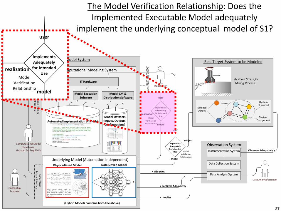
The Model Verification Relationship: Does the Implemented Executable Model adequately
implement the underlying conceptual model of S1?
realization
Implements Adequately for Intended
UseModel
Verification Relationship
model
user

28
Model V&V: We are modeling the learning aspect of System 2 (key to adaptability, agility)
• The Overall Model System is itself being modeled, covering the Life Cycle for a Model.
• Beginning with the Requirements for a Model:– These form the foundation for the model validation
and verification that follow.– Includes many types of models, covering Physics-
Based and Data-Driven Models• The Requirements for a Model include:
– Model System Stakeholder Requirements– Model System Technical Requirements
29
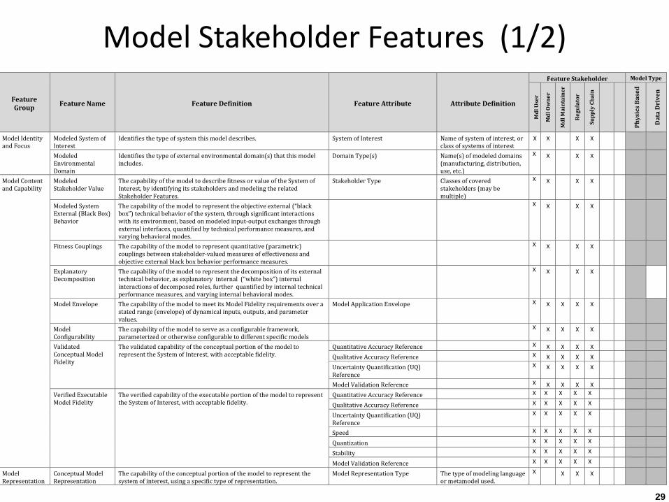
Feature Group Feature Name Feature Definition Feature Attribute Attribute Definition
Feature Stakeholder Model Type
Mdl
Use
r
Mdl
Ow
ner
Mdl
Mai
ntai
ner
Regu
lato
r
Supp
ly C
hain
Phys
ics
Base
d
Dat
a D
rive
n
Model Identity and Focus
Modeled System of Interest
Identifies the type of system this model describes. System of Interest Name of system of interest, or class of systems of interest
X X X X
Modeled Environmental Domain
Identifies the type of external environmental domain(s) that this model includes.
Domain Type(s) Name(s) of modeled domains (manufacturing, distribution, use, etc.)
X X X X
Model Content and Capability
Modeled Stakeholder Value
The capability of the model to describe fitness or value of the System of Interest, by identifying its stakeholders and modeling the related Stakeholder Features.
Stakeholder Type Classes of covered stakeholders (may be multiple)
X X X X
Modeled System External (Black Box) Behavior
The capability of the model to represent the objective external (“black box”) technical behavior of the system, through significant interactions with its environment, based on modeled input-output exchanges through external interfaces, quantified by technical performance measures, and varying behavioral modes.
X X X X
Fitness Couplings The capability of the model to represent quantitative (parametric) couplings between stakeholder-valued measures of effectiveness and objective external black box behavior performance measures.
X X X X
Explanatory Decomposition
The capability of the model to represent the decomposition of its external technical behavior, as explanatory internal (“white box”) internal interactions of decomposed roles, further quantified by internal technical performance measures, and varying internal behavioral modes.
X X X X
Model Envelope The capability of the model to meet its Model Fidelity requirements over a stated range (envelope) of dynamical inputs, outputs, and parameter values.
Model Application Envelope X X X X X
Model Configurability
The capability of the model to serve as a configurable framework, parameterized or otherwise configurable to different specific models
X X X X X
Validated Conceptual Model Fidelity
The validated capability of the conceptual portion of the model to represent the System of Interest, with acceptable fidelity.
Quantitative Accuracy Reference X X X X X Qualitative Accuracy Reference X X X X X Uncertainty Quantification (UQ) Reference
X X X X X
Model Validation Reference X X X X X Verified Executable Model Fidelity
The verified capability of the executable portion of the model to represent the System of Interest, with acceptable fidelity.
Quantitative Accuracy Reference X X X X X Qualitative Accuracy Reference X X X X X Uncertainty Quantification (UQ) Reference
X X X X X
Speed X X X X X Quantization X X X X X Stability X X X X X Model Validation Reference X X X X X
Model Representation
Conceptual Model Representation
The capability of the conceptual portion of the model to represent the system of interest, using a specific type of representation.
Model Representation Type The type of modeling language or metamodel used.
X X X X
Model Stakeholder Features (1/2)

30
Model Utility Perceived Model Value and Use
The relative level of value ascribed to the model, by those who use it for its stated purpose.
User Group Segment The identify of using group segment (multiple)
X X X X
Level of Annual Use The relative level of annual use by the segment
X X X X
Value Level The value class associated with the model by that segment
X X X X
Third Party Acceptance
The degree to which the model is accepted as authoritative, by third party regulators, customers, supply chains, and other entities, for its stated purpose.
Accepting Authority The identity (may be multiple) of regulators, agencies, customers, supply chains, accepting the model
X X X X
Model Ease of Use The perceived ease with which the model can be used, as experienced by its intended users
Perceived Model Complexity High, Medium Low X X X X
Model Life Cycle Management
Model Versioning and Configuration Management
The capability of the model to provide for version and configuration management.
CM Capability Type The type(s) of CM capabilities included (may be multiple)
X X X X X
Managed Model Datasets
The capability of the model to include managed datasets for use as inputs, parametric characterizations, or outputs
Dataset Type The type(s) of data sets (may be multiple)
X X X X
Executable Model Environmental Compatibility
The capability of the model to be compatibly supported by specified information technology environment(s), indicating compatibility, portability, and interoperability.
IT Environmental Component The type(s) of IT environments or standards supported
X X X X X
Model Design Life and Retirement
The capability of the model to be sustained over an indicated design life, and retired on a planned basis.
Design Life The planned retirement date X X X X X
Model Maintainability
The relative ease with which the model can be maintained over its intended life cycle and use, based on capable maintainers, availability of effective model documentation, and degree of complexity of the model
Maintenance Method X
Model Deployability The capability of the model to support deployment into service on behalf of intended users, in its original or subsequent updated versions
Deployment Method X X
Model Cost The financial cost of the model, including development, operating, and maintenance cost
Development Cost The cost to develop the model, including its validation and verification, to its first availability for service date
X
Operational Cost The cost to execute and otherwise operate the model, in standardized execution load units
X
Maintenance Cost The cost to maintain the model
X X
Deployment Cost The cost to deploy, and redeploy updates, per cycle
X X
Retirement Cost The cost to retire the model from service, in a planned fashion
X
Model Availability The degree and timing of availability of the model for its intended use, including date of its first availability and the degree of ongoing availability thereafter.
First Availability Date X X X X X Availability Code X X X X X
Feature Group Feature Name Feature Definition Feature Attribute Attribute Definition
Feature Stakeholder Model Type
Mdl
Use
r
Mdl
Ow
ner
Mdl
Mai
ntai
ner
Regu
lato
r
Supp
ly C
hain
Phys
ics
Base
d
Dat
a D
rive
n
Model Stakeholder Features (2/2)

31
Model Technical Requirements (sample)
• “The model shall identify all the external Domain Actors with which the subject system significantly interacts.”
• “The Model shall identify the external Input-Outputs exchanged during interactions with Domain Actors, and the external Interfaces through which they are exchanged.”
• “The model shall identify and define all the types and instances of Stakeholders with a stake in the System of Interest.”
• “For each Stakeholder, the model shall identify and define all the Stakeholder Features of the System of Interest, representing packages of stakeholder value or fitness for intended use of the System of Interest.”
• “For each identified Stakeholder Feature, the model shall identify and define all the Feature Attributes that parameterize or quantify the degree or type of value or fitness.”
• “The model shall identify the different modes (states) of the system of interest that are significant to the intended use of the model.”
• “The model shall identify the possible (state) transitions between those system modes.”• “For each of its modeled modes (states), the model shall identify which external
interactions the system of interest can have with its environmental actors, from the list of possible interactions.”
Not a specification of a modeling language. Remember it must cover all the requirements for all the types of models—FEA, etc.

32
Observation System
Overall Model System
Computational Modeling System
Real Target System to be Modeled
Automated Implementation of Model
Underlying Model (Automation Independent)
Model User
Conceptual Modeler
Computational Model Developer
(Model Tooling SME)
IT Hardware
Model Authoring Software
Model Execution Software
Model Datasets (Inputs, Outputs, Configurations)
model
realization
Model User Interface
Model Tooling Interface
Instrumentation System
Data Analysis System
Data Collection System
Data Analyst/Scientist
Observes Adequately >
< Confirms Adequately
subject
user
Represents Adequately for Intended
Use Model Validation
Relationship
Implements Adequately for Intended
UseModel
Verification Relationship model
user
< Implies
Conceptual M
odel Interface
Physics-Based Model Data Driven Model
Residual Stress for Milling Process
Model CM & Distribution Software
< Observes
Model Life Cycle Configuration &
Deployment Manager
Model CM
Interface
From: Huanga, Zhanga, Dinga, “An analytical model of residual stress for flank milling of Ti-6Al-4V”, 15th CIRP Conference on Modelling of Machining Operations
(Hybrid Models combine both the above)
State
Input/Output
Interface
Functional Interaction
(Interaction)System
System of Access
attribute
Technical Requirement
Statement
Stakeholder Featureattribute
Design Component
attribute
(physical system)
(logical system)
FunctionalRole
attribute
StakeholderWorld
Language
High LevelRequirements
TechnicalWorld
Language
attribute
Design Constraint Statement
attribute
StakeholderRequirement
Statement
BB
WBDetail Level
Requirements
High LevelDesign
“B” Coupling
“A” Coupling
S*Metamodel forModel-Based Systems Engineering (MBSE)
The S*Metamodel is first of all helping us describe the framework for Requirements on Models, as foundation of ability to subsequently validate and verify those models.

33
Observation System
Overall Model System
Computational Modeling System
Real Target System to be Modeled
Automated Implementation of Model
Underlying Model (Automation Independent)
Model User
Conceptual Modeler
Computational Model Developer
(Model Tooling SME)
IT Hardware
Model Authoring Software
Model Execution Software
Model Datasets (Inputs, Outputs, Configurations)
model
realization
Model User Interface
Model Tooling Interface
Instrumentation System
Data Analysis System
Data Collection System
Data Analyst/Scientist
Observes Adequately >
< Confirms Adequately
subject
user
Represents Adequately for Intended
Use Model Validation
Relationship
Implements Adequately for Intended
UseModel
Verification Relationship model
user
< Implies
Conceptual M
odel Interface
Physics-Based Model Data Driven Model
Residual Stress for Milling Process
Model CM & Distribution Software
< Observes
Model Life Cycle Configuration &
Deployment Manager
Model CM
Interface
From: Huanga, Zhanga, Dinga, “An analytical model of residual stress for flank milling of Ti-6Al-4V”, 15th CIRP Conference on Modelling of Machining Operations
(Hybrid Models combine both the above)
State
Input/Output
Interface
Functional Interaction
(Interaction)System
System of Access
attribute
Technical Requirement
Statement
Stakeholder Featureattribute
Design Component
attribute
(physical system)
(logical system)
FunctionalRole
attribute
StakeholderWorld
Language
High LevelRequirements
TechnicalWorld
Language
attribute
Design Constraint Statement
attribute
StakeholderRequirement
Statement
BB
WBDetail Level
Requirements
High LevelDesign
“B” Coupling
“A” Coupling
S*Metamodel forModel-Based Systems Engineering (MBSE)
S*Pattern Hierarchy for Pattern-Based Systems
Engineering (PBSE)
System Pattern Class Hierarchy
Individual Product or System Configurations
Product Lines orSystem Families
Configure,Specialize
Pattern
Improve Pattern
General System Pattern
V&V of configurable, re-usable models (e.g., S*Patterns) has even greater impact economically, esp. in regulated (think FAA, FDA) markets.

34
Quantitative Fidelity, including Uncertainty Quantification (UQ)
General structure of uncertainty / confidence tracing:• Do the modeled external Interactions qualitatively cover the modeled
Stakeholder Features over the range of intended S1 situations of interest?• Quantify confidence / uncertainty that the modeled Stakeholder Feature
Attributes quantitatively represent the real system concerns of the S1 Stakeholders with sufficient accuracy over the range of intended situation envelopes.
• Quantify confidence / uncertainty that the modeled Technical Performance Attributes quantitatively represent the real system external behavior of the S1 system with sufficient accuracy over the range of intended situation envelopes.
• There is a large body of literature on a mathematical subset of the UQ problem, in ways viewed as the heart of this work.
• But, some additional systems work is needed, and in progress, as to the more general VVUQ framework, suitable for general standards or guidelines.

35
Related activities, communities• ASME Computational Model V&V Committee / Working Groups:
– V&V 10: Verification & Validation in Computational Solid Dynamics– V&V20: Verification & Validation in Computational Fluid Dynamics and Heat Transfer– V&V 30: Verification and Validation in Computational Simulation of Nuclear System
Thermal Fluids Behavior– V&V 40: Verification and Validation in Computational Modeling of Medical Devices– V&V 50: Verification & Validation of Computational Modeling for Advanced
Manufacturing– V&V 60: Verification and Validation in Modeling and Simulation in Energy Systems and
Applications
• INCOSE:– Model-Based Engineering Transformation Initiative– INCOSE-NAFEMS Joint Working Group on Simulation– MBSE Patterns Working Group– Risk Management Working Group– Decision-Management Working Group– Tools Interoperability and Model Life Cycle Management Group– INCOSE-OMG MBSE Initiative

36
Opportunities--what you can do• INCOSE community can learn from ASME efforts, about model V&V• ASME community can learn from INCOSE, about systems-level models• Other professional societies also have an interest at stake in this work• Engineering professional societies (more than trade groups) are in a
good position to collaborate between regulators (e.g., FDA, FAA, etc.) and enterprises/trade groups, as ethical advocates for effective model V&V practice
• How is this related to your enterprise and your own interests?• Do you need to trust models? What models? From suppliers? For
Customers? Others?• Help is needed in this effort—join our communities and effort, or at
least give us feedback

37
References1. Assessing the Reliability of Complex Models: Mathematical and Statistical
Foundations of Verification, Validation, and Uncertainty Quantification ISBN 978-0-309-25634-6 THE NATIONAL ACADEMIES PRESS, http://nap.edu/13395
2. Web site of ASME VV50 https://cstools.asme.org/csconnect/CommitteePages.cfm?Committee=100003367
3. “ASME V&V 10-2006: Guide for Verification and Validation in Computational Solid Mechanics”, ASME, 2006.
4. “ASME V&V 20-2009: Standard for Verification and Validation in Computational Fluid Dynamics and Heat Transfer”, ASME, 2009.
5. “ASME V&V 10.1-2012: An Illustration of the Concepts of Verification and Validation in Computational Solid Mechanics”, ASME, 2012.
6. Journal of Verification, Validation, and Uncertainty Quantification, ASME. https://verification.asmedigitalcollection.asme.org/journal.aspx
7. AIAA (American Institute for Aeronautics and Astronautics). 1998. Guide for the Verification and Validation of Computational Fluid Dynamics Simulations. Reston, Va.: AIAA.
8. Box, G., and N. Draper. Empirical Model Building and Response Surfaces. New York: Wiley, 1987.

38
References, continued9. Hightower, Joseph, “Establishing Model Credibility Using Verification and
Validation”, INCOSE MBSE Workshop, IW2017, Los Angeles, January, 2017. http://www.omgwiki.org/MBSE/lib/exe/fetch.php?media=mbse:incose_mbse_iw_2017:models_and_uncertainty_in_decision_making_rev_a.pptx
10.Beihoff, B., et al, “A World in Motion: INCOSE Vision 2025”, INCOSE.11.Schindel, W., “What Is the Smallest Model of a System?”, Proc. of the INCOSE 2011
International Symposium, International Council on Systems Engineering (2011).12.Schindel, W., and Dove, R., “Introduction to the Agile Systems Engineering Life Cycle
MBSE Pattern”, in Proc. of INCOSE 2016 International Symposium, 2016.13.Schindel, W., “Got Phenomena? Science-Based Disciplines for Emerging Systems
Challenges PBSE methodology summary”, Proc. of INCOSE IS2017 Symposium, Adelaide, UK, 2017.
14.Schindel, W., “Requirements Statements Are Transfer Functions: An Insight from MBSE”, Proc. of INCOSE IS2005 Symposium, Rochester, NY, 2005.
15. INCOSE MBSE Initiative Patterns Working Group web site, at http://www.omgwiki.org/MBSE/doku.php?id=mbse:patterns:patterns
16. INCOSE Patterns Working Group, “MBSE Methodology Summary: Pattern-Based Systems Engineering (PBSE), Based On S*MBSE Models”, V1.5.5A, retrieve from: http://www.omgwiki.org/MBSE/doku.php?id=mbse:pbse

39
Today’s Presentation
Things to Think About
How can this be applied in your work environment?What did you hear that will influence your thinking?
What is your take away from this presentation?

40
PleaseThe link for the online survey for this meeting is
www.surveymonkey.com/r/2017_04_MeetingEvalwww.surveymonkey.com/r/2017_04_MeetingEvalLook in GlobalMeet chat box for cut & paste link.
Slide presentation can be downloaded now/anytime from:The library page at: www.incose.org/enchantment.
Recording will be there in the library tomorrow.