A Dynamic Model for Simulation of Hot Radial Forging Process
6
ScienceDirect Available online at www.sciencedirect.com Procedia Engineering 207 (2017) 478–483 1877-7058 © 2017 The Authors. Published by Elsevier Ltd. Peer-review under responsibility of the scientific committee of the International Conference on the Technology of Plasticity. 10.1016/j.proeng.2017.10.808 © 2017 The Authors. Published by Elsevier Ltd. Peer-review under responsibility of the scientific committee of the International Conference on the Technology of Plasticity. * Corresponding author. Tel.: +44-141-5345641; fax: +44-141-5345200. E-mail address: [email protected] International Conference on the Technology of Plasticity, ICTP 2017, 17-22 September 2017, Cambridge, United Kingdom A Dynamic Model for Simulation of Hot Radial Forging Process Jianglin Huang a *, Carl D. Slater b , Anup Mandral b , Paul Blackwell a a Advanced Forming Research Centre (AFRC), University of Strathclyde, Glasgow, UK b Warwick Manufactruing Group, University of Warwick, Coventry, CV4 7AL, UK Abstract A comprehensive dynamic process model has been developed to investigate features of the inherently transient hot radial forging process, taking account of complex process kinematics, thermo-elastoplastic material behaviour and microstructural evolution. As an input to this model, a fully systematic thermomechanical testing matrix was carried out on a Gleeble 3800 including temperature (20-1100 °C), strain (up to a true strain of 1) and strain rates (from 0.1 to >50 s -1 ). The proposed model can accurately capture vibration characteristics due to the high frequency short strokes during radial forging, which have been found to have a strong effect on material flow, forging load. Numerical analyses were performed to investigate the effect of different axial spring stiffnesses on forging load, strain distribution in the workpiece, and maximum axial feeding rate. It has been found that forging load increases significantly with increasing stiffness of the axial spring. The axial spring stiffness was also found to have a strong effect on determination of axial feeding rate and reduction ratio of workpiece by limiting the axial vibration amplitude of workpiece under the maximum compression of spring coil to avoid hard stop of workpiece in the axial direction during forging. It has been found that the spring stiffness does not have a strong effect on the strain distribution in the work piece. For practical application, the proposed model is applied to simulate the manufacturing process of a hollow transmission shaft using a GFM SKK10/R machine. Simulation results based on a 3 dimensional framework provide a detailed insight of material flow, residual stress and grain size evolution during the multiple pass radial forging process and the results are compared with available experimental measurements. The results provide valuable insights for process design.
Transcript of A Dynamic Model for Simulation of Hot Radial Forging Process
ScienceDirect
Available online at www.sciencedirect.com
Procedia Engineering 207 (2017) 478–483
1877-7058 © 2017 The Authors. Published by Elsevier Ltd.Peer-review under responsibility of the scientific committee of the International Conference on the Technology of Plasticity.10.1016/j.proeng.2017.10.808
10.1016/j.proeng.2017.10.808
© 2017 The Authors. Published by Elsevier Ltd.Peer-review under responsibility of the scientific committee of the International Conference on the Technology of Plasticity.
1877-7058
Available online at www.sciencedirect.com
ScienceDirect Procedia Engineering 00 (2017) 000–000
www.elsevier.com/locate/procedia
1877-7058 © 2017 The Authors. Published by Elsevier Ltd. Peer-review under responsibility of the scientific committee of the International Conference on the Technology of Plasticity.
International Conference on the Technology of Plasticity, ICTP 2017, 17-22 September 2017, Cambridge, United Kingdom
A Dynamic Model for Simulation of Hot Radial Forging Process Jianglin Huanga*, Carl D. Slaterb, Anup Mandralb, Paul Blackwella
aAdvanced Forming Research Centre (AFRC), University of Strathclyde, Glasgow, UK b Warwick Manufactruing Group, University of Warwick, Coventry, CV4 7AL, UK
Abstract
A comprehensive dynamic process model has been developed to investigate features of the inherently transient hot radial forging process, taking account of complex process kinematics, thermo-elastoplastic material behaviour and microstructural evolution. As an input to this model, a fully systematic thermomechanical testing matrix was carried out on a Gleeble 3800 including temperature (20-1100 °C), strain (up to a true strain of 1) and strain rates (from 0.1 to >50 s-1). The proposed model can accurately capture vibration characteristics due to the high frequency short strokes during radial forging, which have been found to have a strong effect on material flow, forging load. Numerical analyses were performed to investigate the effect of different axial spring stiffnesses on forging load, strain distribution in the workpiece, and maximum axial feeding rate. It has been found that forging load increases significantly with increasing stiffness of the axial spring. The axial spring stiffness was also found to have a strong effect on determination of axial feeding rate and reduction ratio of workpiece by limiting the axial vibration amplitude of workpiece under the maximum compression of spring coil to avoid hard stop of workpiece in the axial direction during forging. It has been found that the spring stiffness does not have a strong effect on the strain distribution in the work piece. For practical application, the proposed model is applied to simulate the manufacturing process of a hollow transmission shaft using a GFM SKK10/R machine. Simulation results based on a 3 dimensional framework provide a detailed insight of material flow, residual stress and grain size evolution during the multiple pass radial forging process and the results are compared with available experimental measurements. The results provide valuable insights for process design. © 2017 The Authors. Published by Elsevier Ltd. Peer-review under responsibility of the scientific committee of the International Conference on the Technology
of Plasticity.
* Corresponding author. Tel.: +44-141-5345641; fax: +44-141-5345200.
E-mail address: [email protected]
2 Jianglin Huang et al./ Procedia Engineering 00 (2017) 000–000
Keywords: Radial forging; Axial spring stiffness; Vibration; Grain size Evolution
1. Introduction
Radial forging is an open-die forging process utilizing radially moving dies for reducing the diameters of ingots, bar, rods, and tubes for production of tubular components with different internal and external profiles. The process is fully automated and has good reliability to produce high integrity forgings with tight tolerance, smooth surface, improved mechanical properties at relatively high production rates and low cost. These bring extensive application potentials in aerospace, automotive, and oil and gas industries. Establishing the radial forging procedure is still an expensive and time consuming process based on trial and error, since a number of parameters such as workpiece temperature, rotational speed, feed rate, die geometry, oscillation speed and amplitude etc. need to be determined and optimised to meet stringent requirement of structure and mechanical properties. Recent development on process modelling on radial forging using finite element analysis has been proven to be an accurate approach to improve understanding of the process[1–3].
The challenge of modelling and simulation of the radial forging process is the large number of short and high frequency strokes around the work pieces, which makes the simulation of radial forging process excessively time consuming. With the assumption of predominant radial and axial material flow during the process, radial forging simulation were usually performed in simplified axisymmetric two-dimensional (2D) analysis. The simplified axisymmetric model allows parametric study of effects of different process parameters on material flow [3], and strain heterogeneity [4]. However these 2D models do not fully account for the rotational feed of the billet, and circumferential effect of the forging process. To fully understand the various aspects of hot radial forging process, a 3D model needs to be developed. A symmetric 3D model was developed by Ghaei and Movahhedy [5] to investigate the die design for the radial forging process neglecting the rotational feed of billet. Rong et al. [6] and Chen et al. [7] developed a coupled thermomechanical full 3D FE model to consider the circumferential effect in radial forging process, however simulation was performed only for a short period of actual process time due to the excessively long computation time, which is difficult to reflect the all the characteristics of radial forging process. Another challenge in modelling and simulation of the radial forging` process is the complex process kinematics due to the inherently high frequency of vibration. In previous modelling approaches, a prescribed time dependent velocity or displacement boundary conditions for the gripper cannot capture the correct vibration characteristics of the actual process.
In the present work, a comprehensive 3D dynamic model is proposed to address the above challenges. The main contribution of this paper is to take account of full process kinematics of radial forging by including the axial spring in the process model and investigate the dynamic vibration effect on various aspects of radial forging. Another contribution is the attempt made to predict grain size evolution in 3D radial forging simulation.
Nomenclature
A die oscillation amplitude (mm) l die displacement in radial direction (mm) initial grain size (µm) R universal gas constant (JK-1mol-1) recrystallized grain size (µm) T absolute temperature (K) f die oscillation frequency (Hz) v die axial feeding rate (mm/s) k axial spring stiffness (N/mm) die angle (degree)
2. Modelling Approach
A schematic of the radial forging process is shown in Fig. 1. The workpiece is fixed by a gripper and deformed by 4 radially oscillating dies through high frequency short-strokes. After each stroke, the gripper rotates for a specific angle to obtain a good surface finish of workpiece. To prevent twisting of the workpiece, a high oscillating system is applied to the gripper to interrupt rotation during stoke. After each stroke the workpiece is fed axially towards the hammer die at a specific rate. To stabilize the hammer/workpiece interaction an axial spring bar is connected to the gripper, which allows the workpiece to move in axial direction during stokes. This coordinative
0DdD
Jianglin Huang et al. / Procedia Engineering 207 (2017) 478–483 479
Available online at www.sciencedirect.com
ScienceDirect Procedia Engineering 00 (2017) 000–000
www.elsevier.com/locate/procedia
1877-7058 © 2017 The Authors. Published by Elsevier Ltd. Peer-review under responsibility of the scientific committee of the International Conference on the Technology of Plasticity.
International Conference on the Technology of Plasticity, ICTP 2017, 17-22 September 2017, Cambridge, United Kingdom
A Dynamic Model for Simulation of Hot Radial Forging Process Jianglin Huanga*, Carl D. Slaterb, Anup Mandralb, Paul Blackwella
aAdvanced Forming Research Centre (AFRC), University of Strathclyde, Glasgow, UK b Warwick Manufactruing Group, University of Warwick, Coventry, CV4 7AL, UK
Abstract
A comprehensive dynamic process model has been developed to investigate features of the inherently transient hot radial forging process, taking account of complex process kinematics, thermo-elastoplastic material behaviour and microstructural evolution. As an input to this model, a fully systematic thermomechanical testing matrix was carried out on a Gleeble 3800 including temperature (20-1100 °C), strain (up to a true strain of 1) and strain rates (from 0.1 to >50 s-1). The proposed model can accurately capture vibration characteristics due to the high frequency short strokes during radial forging, which have been found to have a strong effect on material flow, forging load. Numerical analyses were performed to investigate the effect of different axial spring stiffnesses on forging load, strain distribution in the workpiece, and maximum axial feeding rate. It has been found that forging load increases significantly with increasing stiffness of the axial spring. The axial spring stiffness was also found to have a strong effect on determination of axial feeding rate and reduction ratio of workpiece by limiting the axial vibration amplitude of workpiece under the maximum compression of spring coil to avoid hard stop of workpiece in the axial direction during forging. It has been found that the spring stiffness does not have a strong effect on the strain distribution in the work piece. For practical application, the proposed model is applied to simulate the manufacturing process of a hollow transmission shaft using a GFM SKK10/R machine. Simulation results based on a 3 dimensional framework provide a detailed insight of material flow, residual stress and grain size evolution during the multiple pass radial forging process and the results are compared with available experimental measurements. The results provide valuable insights for process design. © 2017 The Authors. Published by Elsevier Ltd. Peer-review under responsibility of the scientific committee of the International Conference on the Technology
of Plasticity.
* Corresponding author. Tel.: +44-141-5345641; fax: +44-141-5345200.
E-mail address: [email protected]
2 Jianglin Huang et al./ Procedia Engineering 00 (2017) 000–000
Keywords: Radial forging; Axial spring stiffness; Vibration; Grain size Evolution
1. Introduction
Radial forging is an open-die forging process utilizing radially moving dies for reducing the diameters of ingots, bar, rods, and tubes for production of tubular components with different internal and external profiles. The process is fully automated and has good reliability to produce high integrity forgings with tight tolerance, smooth surface, improved mechanical properties at relatively high production rates and low cost. These bring extensive application potentials in aerospace, automotive, and oil and gas industries. Establishing the radial forging procedure is still an expensive and time consuming process based on trial and error, since a number of parameters such as workpiece temperature, rotational speed, feed rate, die geometry, oscillation speed and amplitude etc. need to be determined and optimised to meet stringent requirement of structure and mechanical properties. Recent development on process modelling on radial forging using finite element analysis has been proven to be an accurate approach to improve understanding of the process[1–3].
The challenge of modelling and simulation of the radial forging process is the large number of short and high frequency strokes around the work pieces, which makes the simulation of radial forging process excessively time consuming. With the assumption of predominant radial and axial material flow during the process, radial forging simulation were usually performed in simplified axisymmetric two-dimensional (2D) analysis. The simplified axisymmetric model allows parametric study of effects of different process parameters on material flow [3], and strain heterogeneity [4]. However these 2D models do not fully account for the rotational feed of the billet, and circumferential effect of the forging process. To fully understand the various aspects of hot radial forging process, a 3D model needs to be developed. A symmetric 3D model was developed by Ghaei and Movahhedy [5] to investigate the die design for the radial forging process neglecting the rotational feed of billet. Rong et al. [6] and Chen et al. [7] developed a coupled thermomechanical full 3D FE model to consider the circumferential effect in radial forging process, however simulation was performed only for a short period of actual process time due to the excessively long computation time, which is difficult to reflect the all the characteristics of radial forging process. Another challenge in modelling and simulation of the radial forging` process is the complex process kinematics due to the inherently high frequency of vibration. In previous modelling approaches, a prescribed time dependent velocity or displacement boundary conditions for the gripper cannot capture the correct vibration characteristics of the actual process.
In the present work, a comprehensive 3D dynamic model is proposed to address the above challenges. The main contribution of this paper is to take account of full process kinematics of radial forging by including the axial spring in the process model and investigate the dynamic vibration effect on various aspects of radial forging. Another contribution is the attempt made to predict grain size evolution in 3D radial forging simulation.
Nomenclature
A die oscillation amplitude (mm) l die displacement in radial direction (mm) initial grain size (µm) R universal gas constant (JK-1mol-1) recrystallized grain size (µm) T absolute temperature (K) f die oscillation frequency (Hz) v die axial feeding rate (mm/s) k axial spring stiffness (N/mm) die angle (degree)
2. Modelling Approach
A schematic of the radial forging process is shown in Fig. 1. The workpiece is fixed by a gripper and deformed by 4 radially oscillating dies through high frequency short-strokes. After each stroke, the gripper rotates for a specific angle to obtain a good surface finish of workpiece. To prevent twisting of the workpiece, a high oscillating system is applied to the gripper to interrupt rotation during stoke. After each stroke the workpiece is fed axially towards the hammer die at a specific rate. To stabilize the hammer/workpiece interaction an axial spring bar is connected to the gripper, which allows the workpiece to move in axial direction during stokes. This coordinative
0DdD

480 Jianglin Huang et al. / Procedia Engineering 207 (2017) 478–483 Jianglin Huang et al./ Procedia Engineering 00 (2017) 000–000 3
rotation and feed reduce the diameter of workpiece in each pass. After each pass, the hammer dies move in at the radial direction to further reduce the diameter in the next deformation pass. The process is repeated until the whole part is manufactured.
The process model is developed and implemented using the commercial software Abaqus/Explicit (version
6.13-4) to represent the forging process using a GFM SKK10 radial forging machine. The axial spring stiffness is set to 104 N/mm. A rigid contact was defined between the driver and gripper, a small gap of 1 mm between them defines the maximum compression of the axial spring. To simplify the simulation, the axial feed of tube was implemented by moving the four hammer dies towards the tube at 1 mm after each stroke and the driver was kept stationary. The dies oscillate at 20 Hz with an amplitude of 3.5 mm. The displacement in the radial direction is defined as bellow:
(1) The 3D FEM model setup is illustrated in Fig. 2. The initial outer/inner diameters of the tube are 90 mm and
30 mm, respectively. The initial length of the tube is 150 mm. The tube rotates 18 degree after each stroke. A coupled thermal-displacement brick element with reduced integration (C3D8R) and enhanced hourglass control is used to for the workpiece. ALE (Arbitrary Lagrangian–Eulerian) adaptive meshing method is used to cope with large deformation during the radial forging process. All tools are consider as rigid. The friction between the tools and workpiece are constant and described by a penalty formulation and the friction coefficient is set to 0.3.
The flow stress of material were obtained from a continuous hot compression tests carried out on a Gleeble 3800. It needs to be pointed out that the interrupted nature of deformation may affect the flow stress, so the testing method used in this work is a simplified approach to identify the flow stress, neglecting the short interruption due the high frequency strokes. The material used in the simulation is 20MnCr5 with a starting forging temperature of 1000°C. Temperature and strain rate dependent stress-strain curves are shown in Fig. 3. The Johnson-Mehl- Avrami-Kohnogorov (JMAK) based model is implemented in Abaqus to predict grain size evolution during radial forging using recrystallisation kinetics model from literature [8]. The dynamic recrystallized (DRX) grain size is described as follows:
(2)
Fig. 1. Radial forging process (a) Axial spring in the GFM SKK 10 radial forging machine, and (b) schematic representation of the radial forging. process of a tube with a mandrel.
Fig. 2. Illustration of 3D FEM model setup.
sin(2 )l A ft
0.270.27
0310244expdD D
RT
4 Jianglin Huang et al./ Procedia Engineering 00 (2017) 000–000
3. Results and discussion
3.1. Vibration characteristics of radial forging
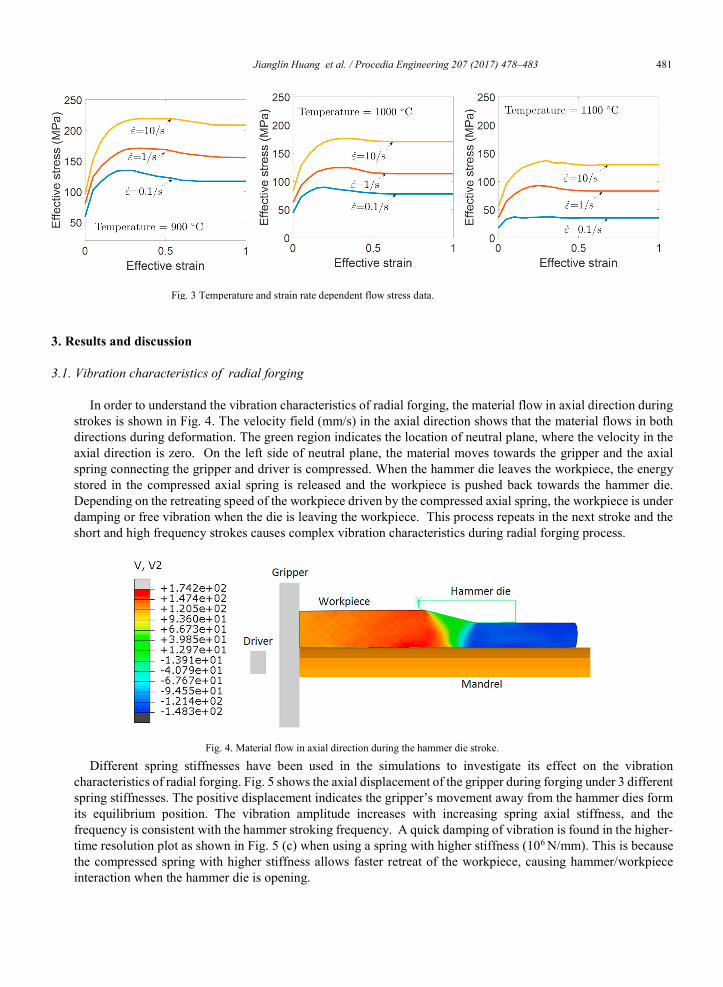
In order to understand the vibration characteristics of radial forging, the material flow in axial direction during strokes is shown in Fig. 4. The velocity field (mm/s) in the axial direction shows that the material flows in both directions during deformation. The green region indicates the location of neutral plane, where the velocity in the axial direction is zero. On the left side of neutral plane, the material moves towards the gripper and the axial spring connecting the gripper and driver is compressed. When the hammer die leaves the workpiece, the energy stored in the compressed axial spring is released and the workpiece is pushed back towards the hammer die. Depending on the retreating speed of the workpiece driven by the compressed axial spring, the workpiece is under damping or free vibration when the die is leaving the workpiece. This process repeats in the next stroke and the short and high frequency strokes causes complex vibration characteristics during radial forging process.
Different spring stiffnesses have been used in the simulations to investigate its effect on the vibration characteristics of radial forging. Fig. 5 shows the axial displacement of the gripper during forging under 3 different spring stiffnesses. The positive displacement indicates the gripper’s movement away from the hammer dies form its equilibrium position. The vibration amplitude increases with increasing spring axial stiffness, and the frequency is consistent with the hammer stroking frequency. A quick damping of vibration is found in the higher-time resolution plot as shown in Fig. 5 (c) when using a spring with higher stiffness (106 N/mm). This is because the compressed spring with higher stiffness allows faster retreat of the workpiece, causing hammer/workpiece interaction when the hammer die is opening.
Fig. 3 Temperature and strain rate dependent flow stress data.
Fig. 4. Material flow in axial direction during the hammer die stroke.
Jianglin Huang et al. / Procedia Engineering 207 (2017) 478–483 481 Jianglin Huang et al./ Procedia Engineering 00 (2017) 000–000 3
rotation and feed reduce the diameter of workpiece in each pass. After each pass, the hammer dies move in at the radial direction to further reduce the diameter in the next deformation pass. The process is repeated until the whole part is manufactured.
The process model is developed and implemented using the commercial software Abaqus/Explicit (version
6.13-4) to represent the forging process using a GFM SKK10 radial forging machine. The axial spring stiffness is set to 104 N/mm. A rigid contact was defined between the driver and gripper, a small gap of 1 mm between them defines the maximum compression of the axial spring. To simplify the simulation, the axial feed of tube was implemented by moving the four hammer dies towards the tube at 1 mm after each stroke and the driver was kept stationary. The dies oscillate at 20 Hz with an amplitude of 3.5 mm. The displacement in the radial direction is defined as bellow:
(1) The 3D FEM model setup is illustrated in Fig. 2. The initial outer/inner diameters of the tube are 90 mm and
30 mm, respectively. The initial length of the tube is 150 mm. The tube rotates 18 degree after each stroke. A coupled thermal-displacement brick element with reduced integration (C3D8R) and enhanced hourglass control is used to for the workpiece. ALE (Arbitrary Lagrangian–Eulerian) adaptive meshing method is used to cope with large deformation during the radial forging process. All tools are consider as rigid. The friction between the tools and workpiece are constant and described by a penalty formulation and the friction coefficient is set to 0.3.
The flow stress of material were obtained from a continuous hot compression tests carried out on a Gleeble 3800. It needs to be pointed out that the interrupted nature of deformation may affect the flow stress, so the testing method used in this work is a simplified approach to identify the flow stress, neglecting the short interruption due the high frequency strokes. The material used in the simulation is 20MnCr5 with a starting forging temperature of 1000°C. Temperature and strain rate dependent stress-strain curves are shown in Fig. 3. The Johnson-Mehl- Avrami-Kohnogorov (JMAK) based model is implemented in Abaqus to predict grain size evolution during radial forging using recrystallisation kinetics model from literature [8]. The dynamic recrystallized (DRX) grain size is described as follows:
(2)
Fig. 1. Radial forging process (a) Axial spring in the GFM SKK 10 radial forging machine, and (b) schematic representation of the radial forging. process of a tube with a mandrel.
Fig. 2. Illustration of 3D FEM model setup.
sin(2 )l A ft
0.270.27
0310244expdD D
RT
4 Jianglin Huang et al./ Procedia Engineering 00 (2017) 000–000
3. Results and discussion
3.1. Vibration characteristics of radial forging
In order to understand the vibration characteristics of radial forging, the material flow in axial direction during strokes is shown in Fig. 4. The velocity field (mm/s) in the axial direction shows that the material flows in both directions during deformation. The green region indicates the location of neutral plane, where the velocity in the axial direction is zero. On the left side of neutral plane, the material moves towards the gripper and the axial spring connecting the gripper and driver is compressed. When the hammer die leaves the workpiece, the energy stored in the compressed axial spring is released and the workpiece is pushed back towards the hammer die. Depending on the retreating speed of the workpiece driven by the compressed axial spring, the workpiece is under damping or free vibration when the die is leaving the workpiece. This process repeats in the next stroke and the short and high frequency strokes causes complex vibration characteristics during radial forging process.
Different spring stiffnesses have been used in the simulations to investigate its effect on the vibration characteristics of radial forging. Fig. 5 shows the axial displacement of the gripper during forging under 3 different spring stiffnesses. The positive displacement indicates the gripper’s movement away from the hammer dies form its equilibrium position. The vibration amplitude increases with increasing spring axial stiffness, and the frequency is consistent with the hammer stroking frequency. A quick damping of vibration is found in the higher-time resolution plot as shown in Fig. 5 (c) when using a spring with higher stiffness (106 N/mm). This is because the compressed spring with higher stiffness allows faster retreat of the workpiece, causing hammer/workpiece interaction when the hammer die is opening.
Fig. 3 Temperature and strain rate dependent flow stress data.
Fig. 4. Material flow in axial direction during the hammer die stroke.
482 Jianglin Huang et al. / Procedia Engineering 207 (2017) 478–483 Jianglin Huang et al./ Procedia Engineering 00 (2017) 000–000 5
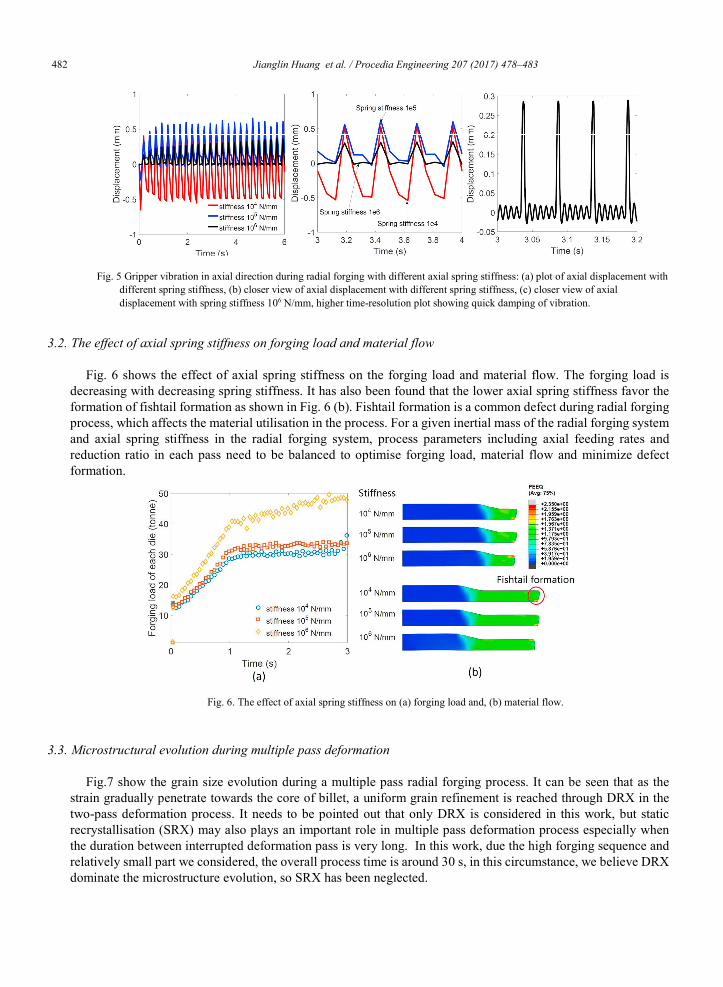
3.2. The effect of axial spring stiffness on forging load and material flow
Fig. 6 shows the effect of axial spring stiffness on the forging load and material flow. The forging load is decreasing with decreasing spring stiffness. It has also been found that the lower axial spring stiffness favor the formation of fishtail formation as shown in Fig. 6 (b). Fishtail formation is a common defect during radial forging process, which affects the material utilisation in the process. For a given inertial mass of the radial forging system and axial spring stiffness in the radial forging system, process parameters including axial feeding rates and reduction ratio in each pass need to be balanced to optimise forging load, material flow and minimize defect formation.
3.3. Microstructural evolution during multiple pass deformation
Fig.7 show the grain size evolution during a multiple pass radial forging process. It can be seen that as the strain gradually penetrate towards the core of billet, a uniform grain refinement is reached through DRX in the two-pass deformation process. It needs to be pointed out that only DRX is considered in this work, but static recrystallisation (SRX) may also plays an important role in multiple pass deformation process especially when the duration between interrupted deformation pass is very long. In this work, due the high forging sequence and relatively small part we considered, the overall process time is around 30 s, in this circumstance, we believe DRX dominate the microstructure evolution, so SRX has been neglected.
Fig. 5 Gripper vibration in axial direction during radial forging with different axial spring stiffness: (a) plot of axial displacement with different spring stiffness, (b) closer view of axial displacement with different spring stiffness, (c) closer view of axial displacement with spring stiffness 106 N/mm, higher time-resolution plot showing quick damping of vibration.
Fig. 6. The effect of axial spring stiffness on (a) forging load and, (b) material flow.
6 Jianglin Huang et al./ Procedia Engineering 00 (2017) 000–000
4. Summary and conclusion
A comprehensive dynamic model has been developed to improve the fundamental understanding of the hot radial forging process. The results are summarized as follows:
(1) Material flows in both directions during stoke and a neutral plane is well captured. (2) Dynamic effect in radial forging process is modeled and vibration characteristics are well understood. (3) The axial spring stiffness has been found to have a strong effect on forging load and material flow. (4) The effect of DRX has been considered to predict grain size evolution during radial forging process. The present model provides detailed insight in the radial forging process and has penitential application on
process optimization. Model calibration is still ongoing using data from forging trials to be produced with the newly available GFM SKK10/R radial forging machine at AFRC. Additional material tests need to be done to refine the microstructure model for better predictive capability of microstructural evolution.
Acknowledgement
Authors gratefully acknowledge the financial support by Innovate UK for the innovative research project led by Jaguar Land Rover Ltd., TRANSCEND – TRANsmission Supply Chain Excellence for Next generation Dual clutch technologies (Reference 113061). Authors also would like to thanks the following individuals from AFRC: Gerard Brown, Gordon Gourlay, Mark O’Hare and Kadir Paslioglu. Stefan Stockinger from GFM Austria is also appreciated for the detailed discussion of radial forging process.
References
[1] P. Groche, M. Krech, Efficient production of sensory machine elements by a two-stage rotary swaging process—Relevant phenomena and numerical modelling, J. Mater. Process. Technol. 242 (2017) 205–217.
[2] L. Fan, Z. Wang, H. Wang, 3D finite element modeling and analysis of radial forging processes, J. Manuf. Process. 16 (2014) 329–334. [3] E. Moumi, S. Ishkina, B. Kuhfuss, T. Hochrainer, A. Struss, M. Hunkel, 2D-simulation of Material Flow During Infeed Rotary
Swaging Using Finite Element Method, Procedia Eng. 81 (2014) 2342–2347. [4] M. Sanjari, P. Saidi, A.K. Taheri, M. Hossein-Zadeh, Determination of strain field and heterogeneity in radial forging of tube using
finite element method and microhardness test, Mater. Des. 38 (2012) 147–153. [5] A. Ghaei, M.R. Movahhedy, Die design for the radial forging process using 3D FEM, J. Mater. Process. Technol. 182 (2007) 534–539. [6] L. Rong, Z. Nie, T. Zuo, 3D finite element modeling of cogging-down rotary swaging of pure magnesium square billet—Revealing the
effect of high-frequency pulse stroking, Mater. Sci. Eng. A. 464 (2007) 28–37. [7] J. Chen, K. Chandrashekhara, V.L. Richards, S.N. Lekakh, Three-Dimensional Nonlinear Finite Element Analysis of Hot Radial
Forging Process for Large Diameter Tubes, Mater. Manuf. Process. 25 (2010) 669–678. [8] E.S. Puchi-Cabrera, J.-D. Guérin, M. Dubar, M.H. Staia, J. Lesage, D. Chicot, Constitutive description for the design of hot-working
operations of a 20MnCr5 steel grade, Mater. Des. 62 (2014) 255–264.
Fig.7. Multiple-pass radial forging process: evolution of (a) equivalent strain, and (b) grain size (mm).

Jianglin Huang et al. / Procedia Engineering 207 (2017) 478–483 483 Jianglin Huang et al./ Procedia Engineering 00 (2017) 000–000 5
3.2. The effect of axial spring stiffness on forging load and material flow
Fig. 6 shows the effect of axial spring stiffness on the forging load and material flow. The forging load is decreasing with decreasing spring stiffness. It has also been found that the lower axial spring stiffness favor the formation of fishtail formation as shown in Fig. 6 (b). Fishtail formation is a common defect during radial forging process, which affects the material utilisation in the process. For a given inertial mass of the radial forging system and axial spring stiffness in the radial forging system, process parameters including axial feeding rates and reduction ratio in each pass need to be balanced to optimise forging load, material flow and minimize defect formation.
3.3. Microstructural evolution during multiple pass deformation
Fig.7 show the grain size evolution during a multiple pass radial forging process. It can be seen that as the strain gradually penetrate towards the core of billet, a uniform grain refinement is reached through DRX in the two-pass deformation process. It needs to be pointed out that only DRX is considered in this work, but static recrystallisation (SRX) may also plays an important role in multiple pass deformation process especially when the duration between interrupted deformation pass is very long. In this work, due the high forging sequence and relatively small part we considered, the overall process time is around 30 s, in this circumstance, we believe DRX dominate the microstructure evolution, so SRX has been neglected.
Fig. 5 Gripper vibration in axial direction during radial forging with different axial spring stiffness: (a) plot of axial displacement with different spring stiffness, (b) closer view of axial displacement with different spring stiffness, (c) closer view of axial displacement with spring stiffness 106 N/mm, higher time-resolution plot showing quick damping of vibration.
Fig. 6. The effect of axial spring stiffness on (a) forging load and, (b) material flow.
6 Jianglin Huang et al./ Procedia Engineering 00 (2017) 000–000
4. Summary and conclusion
A comprehensive dynamic model has been developed to improve the fundamental understanding of the hot radial forging process. The results are summarized as follows:
(1) Material flows in both directions during stoke and a neutral plane is well captured. (2) Dynamic effect in radial forging process is modeled and vibration characteristics are well understood. (3) The axial spring stiffness has been found to have a strong effect on forging load and material flow. (4) The effect of DRX has been considered to predict grain size evolution during radial forging process. The present model provides detailed insight in the radial forging process and has penitential application on
process optimization. Model calibration is still ongoing using data from forging trials to be produced with the newly available GFM SKK10/R radial forging machine at AFRC. Additional material tests need to be done to refine the microstructure model for better predictive capability of microstructural evolution.
Acknowledgement
Authors gratefully acknowledge the financial support by Innovate UK for the innovative research project led by Jaguar Land Rover Ltd., TRANSCEND – TRANsmission Supply Chain Excellence for Next generation Dual clutch technologies (Reference 113061). Authors also would like to thanks the following individuals from AFRC: Gerard Brown, Gordon Gourlay, Mark O’Hare and Kadir Paslioglu. Stefan Stockinger from GFM Austria is also appreciated for the detailed discussion of radial forging process.
References
[1] P. Groche, M. Krech, Efficient production of sensory machine elements by a two-stage rotary swaging process—Relevant phenomena and numerical modelling, J. Mater. Process. Technol. 242 (2017) 205–217.
[2] L. Fan, Z. Wang, H. Wang, 3D finite element modeling and analysis of radial forging processes, J. Manuf. Process. 16 (2014) 329–334. [3] E. Moumi, S. Ishkina, B. Kuhfuss, T. Hochrainer, A. Struss, M. Hunkel, 2D-simulation of Material Flow During Infeed Rotary
Swaging Using Finite Element Method, Procedia Eng. 81 (2014) 2342–2347. [4] M. Sanjari, P. Saidi, A.K. Taheri, M. Hossein-Zadeh, Determination of strain field and heterogeneity in radial forging of tube using
finite element method and microhardness test, Mater. Des. 38 (2012) 147–153. [5] A. Ghaei, M.R. Movahhedy, Die design for the radial forging process using 3D FEM, J. Mater. Process. Technol. 182 (2007) 534–539. [6] L. Rong, Z. Nie, T. Zuo, 3D finite element modeling of cogging-down rotary swaging of pure magnesium square billet—Revealing the
effect of high-frequency pulse stroking, Mater. Sci. Eng. A. 464 (2007) 28–37. [7] J. Chen, K. Chandrashekhara, V.L. Richards, S.N. Lekakh, Three-Dimensional Nonlinear Finite Element Analysis of Hot Radial
Forging Process for Large Diameter Tubes, Mater. Manuf. Process. 25 (2010) 669–678. [8] E.S. Puchi-Cabrera, J.-D. Guérin, M. Dubar, M.H. Staia, J. Lesage, D. Chicot, Constitutive description for the design of hot-working
operations of a 20MnCr5 steel grade, Mater. Des. 62 (2014) 255–264.
Fig.7. Multiple-pass radial forging process: evolution of (a) equivalent strain, and (b) grain size (mm).