A CsI(Tl) Scintillating Crystal Detector for the Studies ... · Scintillating crystal detector may...
34
AS-TEXONO/00-01 A CsI(Tl) Scintillating Crystal Detector for the Studies of Low Energy Neutrino Interactions H.B. Li a,b , Y. Liu c , C.C. Chang d , C.Y. Chang d , J.H. Chao e , C.P. Chen a , T.Y. Chen f , M. He g , L. Hou h , G.C. Kiang a , W.P. Lai a , S.C. Lee a , J. Li c , J.G. Lu c , Z.P. Mao c , H.Y. Sheng a,c , R.F. Su i , P.K. Teng a , C.W. Wang a , S.C. Wang a , H.T. Wong a, 1 , T.R. Yeh j , Z.Y. Zhang k , D.X. Zhao a,c , S.Q. Zhao c , Z.Y. Zhou h , B.A. Zhuang a,c The TEXONO 2 Collaboration a Institute of Physics, Academia Sinica, Taipei, Taiwan. b Department of Physics, National Taiwan University, Taipei, Taiwan. c Institute of High Energy Physics, Beijing, China. d Department of Physics, University of Maryland, College Park, U.S.A. e Nuclear Science and Technology Development Center, National Tsing Hua University, Hsinchu, Taiwan. f Department of Physics, Nanjing University, Nanjing, China. g Department of Physics, Shandong University, Jinan, China. h Department of Nuclear Physics, Institute of Atomic Energy, Beijing, China. i Nuclear Engineering Division, Nuclear Power Plant II, Kuosheng, Taiwan. j Engineering Division, Institute of Nuclear Energy Research, Lungtan, Taiwan. k Department of Electronics, Institute of Radiation Protection, Taiyuan, China. 1 Corresponding author: Email: [email protected]; Tel:+886-2-2789-9682; FAX:+886-2-2788- 9828. 2 Taiwan EXperiment On NeutrinO 1
Transcript of A CsI(Tl) Scintillating Crystal Detector for the Studies ... · Scintillating crystal detector may...
AS-TEXONO/00-01
A CsI(Tl) Scintillating Crystal Detector for the Studies of
Low Energy Neutrino Interactions
H.B. Lia,b, Y. Liuc, C.C. Changd, C.Y. Changd, J.H. Chaoe, C.P. Chena, T.Y. Chenf ,
M. Heg, L. Houh, G.C. Kianga, W.P. Laia, S.C. Leea, J. Lic, J.G. Luc, Z.P. Maoc,
H.Y. Shenga,c, R.F. Sui, P.K. Tenga, C.W. Wanga, S.C. Wanga, H.T. Wonga,1,
T.R. Yehj , Z.Y. Zhangk, D.X. Zhaoa,c, S.Q. Zhaoc, Z.Y. Zhouh, B.A. Zhuanga,c
The TEXONO2 Collaboration
a Institute of Physics, Academia Sinica, Taipei, Taiwan.b Department of Physics, National Taiwan University, Taipei, Taiwan.c Institute of High Energy Physics, Beijing, China.d Department of Physics, University of Maryland, College Park, U.S.A.e Nuclear Science and Technology Development Center, National Tsing Hua University,
Hsinchu, Taiwan.f Department of Physics, Nanjing University, Nanjing, China.g Department of Physics, Shandong University, Jinan, China.h Department of Nuclear Physics, Institute of Atomic Energy, Beijing, China.i Nuclear Engineering Division, Nuclear Power Plant II, Kuosheng, Taiwan.j Engineering Division, Institute of Nuclear Energy Research, Lungtan, Taiwan.k Department of Electronics, Institute of Radiation Protection, Taiyuan, China.
1Corresponding author: Email: [email protected]; Tel:+886-2-2789-9682; FAX:+886-2-2788-9828.
2Taiwan EXperiment On NeutrinO
1

Abstract
Scintillating crystal detector may offer some potential advantages in the low-energy,
low-background experiments. A 500 kg CsI(Tl) detector to be placed near the core of Nu-
clear Power Station II in Taiwan is being constructed for the studies of electron-neutrino
scatterings and other keV−MeV range neutrino interactions. The motivations of this
detector approach, the physics to be addressed, the basic experimental design, and the
characteristic performance of prototype modules are described. The expected background
channels and their experimental handles are discussed.
PACS Codes: 14.60.Pq; 29.40.Mc
Keywords: Neutrinos; Scintillation detector
2

1 Introduction
Scintillating crystal detectors [1] have been widely used as electromagnetic calorimeters in
high energy physics [2], as well as in medical and security imaging and in the oil-extraction
industry. They offer many potentials merits [3] for low-energy (keV-MeV range) low
background experiments.
A CsI(Tl) scintillating crystal detector is being constructed to be placed near a reactor
core to study low energy neutrino interactions [4]. In subsequent sections, we discuss the
motivations for this choice of detector technology, the physics topics to be addressed,
the basic experimental design and the prototype performance parameters. The various
background processes and the experimental means to identify and suppress them are
considered. Various extensions based on this detector technique are summarized at the
end.
2 Physics and Detector Motivations
High energy (GeV) neutrino beams from accelerators have been very productive in the
investigations of electroweak, QCD and structure function physics [5] and have blossomed
into matured programs at CERN and Fermilab. However, the use of low energy (MeV)
neutrino as a probe to study particle and nuclear physics has not been well explored.
Nuclear power reactors are abundant source of electron anti-neutrinos (νe) at the MeV
range. Previous experiments with reactor neutrinos primarily focused on the interactions
νe + p → e+ + n
to look for neutrino oscillations [6]. The choice of this interaction channel is due to its
relatively large cross-sections, the very distinct experimental signatures (prompt e+ fol-
lowed by a delayed neutron capture), and the readily available detector choice of liquid
scintillator providing the proton target. Using this interaction, the reactor neutrino spec-
trum has been measured to a precision of ∼2% in the 3 MeV to 7 MeV range from the
Bugey experiment [7].
The only other processes measured at the MeV range for νe are νe-electron [8, 9, 10] and
νe-deuteron [11] interactions, and their accuracies are at the 30-50% and 10-20% range,
respectively. There are motivations to improve on these measurements, to investigate
complementary detection techniques, and to study the other unexplored channels.
3
Gamma-ray spectroscopy has been a standard technique in nuclear sciences (that is,
in the investigations of physics at the MeV range), with the use of scintillating crystals
or solid-state detectors. Gamma-lines of characteristic energies give unambiguous infor-
mation on the presence and transitions of whichever specific isotopes, allowing a unique
interpretation of both the signal and background processes.
Several intrinsic properties of crystal scintillators make them attractive candidates for
low-background experiments [3] in neutrino and astro-particle physics. The experimental
difficulties of building a high-quality gamma detector for MeV neutrino physics have been
the large target mass required. However, in recent years, big electro-magnetic calorimeter
systems [2] (such as the mass of 40 tons of CsI(Tl) crystals, in the case for the current
B-factories experiments [12]) have been built for high energy physics experiments, using
CsI(Tl) crystals [13] with silicon PIN photo-diodes readout [14]. In addition, NaI(Tl) de-
tectors with the mass range of 100 kg have been used in Dark Matter WIMP searches [15],
producing some of the most sensitive results.
The CsI-crystal production technology is by now well matured and the cost has been
reduced enormously due to the large demands. It becomes realistic and affordable to build
a CsI detector in the range of 1-ton in target mass for a reactor neutrino experiment.
The detector is technically much simpler to build and to operate than, for instance, gas
chambers and liquid scintillators. The detector mass can be readily scaled up to tens
of tons if the first experiment would yield interesting results or lead to other potential
applications. Other scintillating crystal detectors can be easily customized in the various
potential applications.
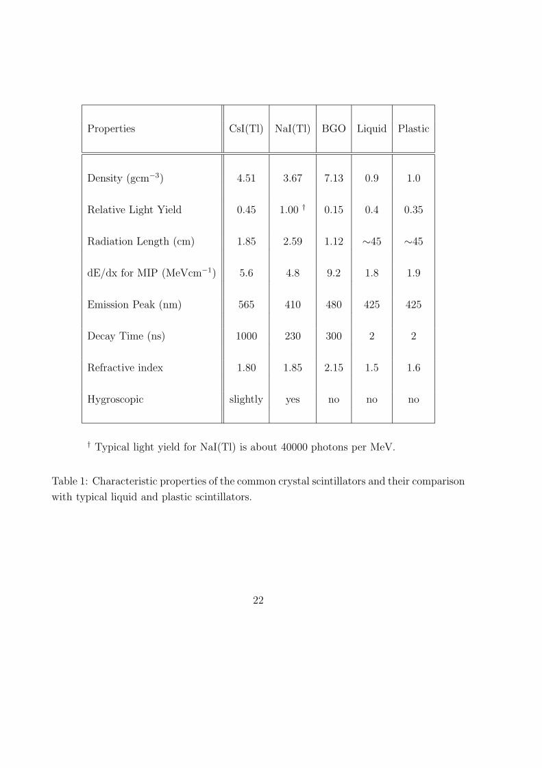
The properties of CsI(Tl) crystals, together with those of a few common scintillators,
are listed in Table 1. The CsI(Tl) crystal offers certain advantages over the other possi-
bilities. It has relatively high light yield and high photon absorption (or short radiation
length). It is mechanically stable and easy to machine, and is only weakly hygroscopic.
There is no need for a hermetic container to seal the detector from the ambient humidity
(as required, for instance, by NaI(Tl)). This minimizes radioactive background as well as
energy loss in the passive elements which will degrade energy resolution. In particular,
CsI(Tl) provides strong attenuation for γ’s of energy less than 500 keV. As a result, it is
possible to realize a compact detector design with minimal passive materials within the
fiducial volume, and with an efficient external shielding configuration.
4

3 Neutrino Interactions on CsI(Tl)
3.1 Neutrino-Electron Scattering
The cross section for the process
νe + e− → νe + e−
gives information on the electro-weak parameters (gV, gA, and sin2θW), and are sen-
sitive to small neutrino magnetic moments (µν) and the mean square charge radius
(< r2 >) [16, 17]. Scatterings of the (νe e) [19] and (νe e) are two of the most realistic
systems where the interference effects between Z [neutral currents (NC)] and W [charged
currents (CC)] exchanges can be studied [18]. Many of the existing and proposed solar
neutrino detectors (Super-Kamiokande, Borexino, HELLAZ, HERON ...) [20] make use
of the νe-e interactions as their detection mechanisms. The fact the νe-e scattering can
proceed via both W and Z exchanges, while νµ-e and ντ -e are purely neutral current
processes, is the physics-basis of Resonance Neutrino Oscillation in Matter (the “MSW”
Effect) [21].
In an experiment, what can be measured is the recoil energy of the electron (T). The
differential cross section can be expressed as :
dσ
dT(ν e) =
G2F me
2π[(gV ± x± gA)2 + (gV ± x∓ gA)2[1− T
Eν
]2 + (g2A − (gV ± x)2)
meT
E2ν
]
+πα2
emµ2ν
m2e
[1− T/Eν
T]
where gV = 2 sin2θW − 12
and gA = −12
in the Standard Model, while the upper (lower)
signs refer to νµ e and ντ e (νµ e and ντ e) scatterings where only NC are involved, and
x =2M2
W
3< r2 >sin2θW .
For νe e scattering, both NC and CC and their interference terms contribute, so that the
cross sections can be evaluated by replacing gV → gV + 1 and gA → gA + 1. The µν
term have a 1T
dependence. Accordingly, experimental searches for the neutrino magnetic
moment should focus on the reduction of the threshold (usually background-limited) for
the recoil electron energy.
The gA Vs. gV parameter space where (νe e) scatterings are sensitive to is depicted in
Figure 1. The complementarity with (νµ e, νµ e, νe e) can be readily seen. The expected
5

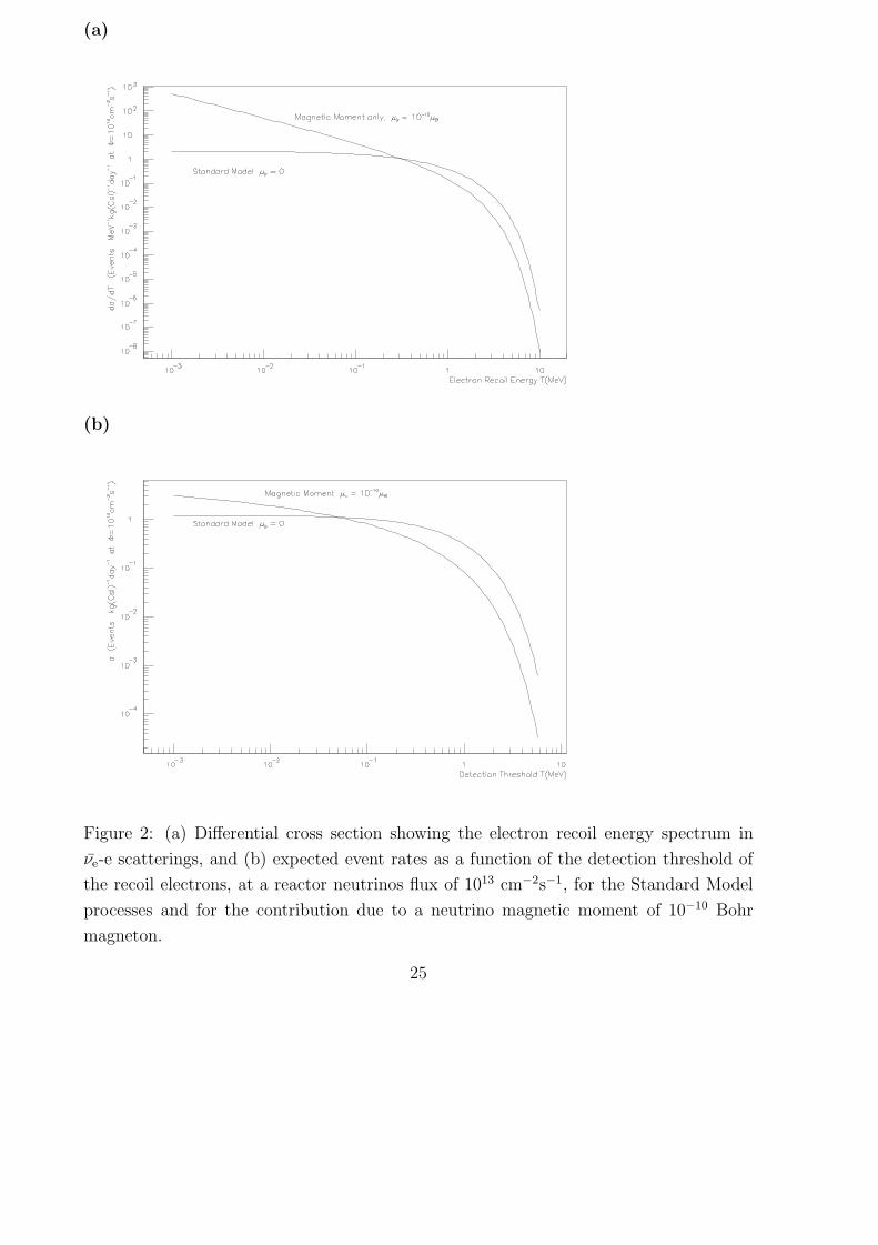
recoil energy spectrum [17] is displayed in Figure 2a, showing standard model expectations
and the case with an anomalous neutrino magnetic moment of 10−10 µB. The present
published limit [10] is 1.9× 10⁻¹⁰ µB. The number of events in the two cases as a function
of measurement threshold is depicted in Figure 2b. It can be seen that the rate is at the
range of O(1) events per kg of CsI(Tl) per day [≡ “pkd”]3 at about 100 keV threshold at
a reactor neutrino flux of 1013 cm−2s−1, which poses formidable experimental challenge
in terms of background control.
Therefore, investigations of (νe e) cross-sections with reactor neutrinos allow one to
study electro-weak physics at the MeV range, to probe charged and neutral currents
interference, and to look for an anomalous neutrino magnetic moment. The present ex-
perimental situations are discussed in Ref. [22] and summarized in Table 2. In particular,
a re-analysis [17] of the Savannah River results [8], based on an improved reactor neutrino
spectrum and the Standard Model sin2θW value, suggested that the measured (νe e) cross-
sections at 1.5-3.0 MeV and 3.0-4.5 MeV are 1.35±0.4 and 2.0±0.5 times, respectively,
larger than the expected values, and can be interpreted to be consistent with a µν at
the range of (2-4)X10−10 µB. Various astrophysics considerations from the time duration
of the supernova SN1987A burst [23], stellar cooling [24] and Big Bang Nucleosynthe-
sis [25] provide more stringent bounds on µν to the 10−11 − 1013 µB level, but these are
model-dependent. An anomalous neutrino magnetic moment of range µν ∼ 10−10 µB has
been considered as a solution to the Solar Neutrino Puzzle [26]. There are motivations to
improve the cross-section measurements and magnetic moment sensitivities further with
laboratory experiments. Several other projects are underway [22, 27].
A 500 kg CsI(Tl) crystal calorimeter (fiducial mass 200-300 kg) will have more target
electrons than previous experiments [8, 9, 10] and current projects [22, 27], as shown in
Table 2. The signature for (νe e) will be a single hit out of the several hundred channels.
As discussed in Section 6, the crystal scintillator approach may provide low detection
threshold, high photon attenuation, and powerful diagnostic capabilities for background
understanding. All these features can potentially improve the sensitivities for both cross-
section measurements and magnetic moments studies.
3For simplicity, we denote “events per kg of CsI(Tl) per day” by pkd in this article.
6
3.2 Neutrino Interactions on 133Cs and 127I
Neutral current excitation (NCEX) on nuclei by neutrinos
νe + (A, Z) → νe + (A, Z)∗
has been observed only in the case of 12C [28] with intermediate energy (O(10 MeV))
neutrinos. Excitations with lower energies using reactor neutrinos have been studied
theoretically [29] but not observed.
Crystal scintillators, having good γ resolution and capture efficiency, are suitable to
study these processes. The experimental signatures will be an excess of events at the
characteristic gamma-energies correlated to the Reactor-ON period. Using CsI(Tl) as
active target nuclei, the candidate γ-lines with M1 transitions include 81 and 160 keV for133Cs, and 58, 202 and 418 keV for 127I. The use of NCEX as the detection mechanisms for
solar neutrinos [30, 31] and Dark Matter-WIMPs [32] have been discussed. Competitive
limits have been set with the WIMP-searches based on the NCEX channel with 127I [33]
and 129Xe [34].
There are no theoretical predictions for these transitions for 133Cs and 127I. One may
expect a similar range as the 480 keV case for 7Li [29], which would be O(0.01-0.1) pkd
at a reactor neutrino flux of 1013 cm−2s−1. In addition, there are theoretical work [35]
suggesting that the NCEX cross-sections on 10B and 11B are sensitive to the axial isoscalar
component of NC interactions and the strange quark content of the nucleon. The studies
of neutrino-induced interactions on nuclei is one of the principal program of the ORLaND
proposal [36] based on intermediate energy neutrinos from spallation neutron source.
For completeness, we mention that νe can also interact with 133Cs and 127I via the
charged-current (CC) channels. There are two modes: (I) Inverse beta decay
νe + (A, Z) → e+ + (A, Z− 1)∗
have the distinct signatures of 2 back-to-back 511 keV γs from the positron annihila-
tion, plus the characteristic γ-lines from the daughter nuclei, and the positron itself; (II)
Resonant orbital electron capture
νe + e− + (A, Z) → (A, Z− 1)∗
takes place only at a narrow range of neutrino energy equal to the Q-value of the transi-
tion. The signatures are the characteristic gamma lines for the excited daughter nuclei.
Calculation does not exist but the event rates are expected to be further suppressed since
7

they involve the conversion of a proton to a neutron in neutron-rich nuclei. The νeN-CC
interactions have been considered to detect the low-energy terrestrial neutrinos due to the
radioactivity at the Earth’s lithosphere [37].
4 Experimental Design
Since mid-1997, a Collaboration has been built up [38] to pursue an experimental program
discussed in Section 3 − the studies of low energy neutrino interactions using reactor
neutrinos as source with CsI(Tl) crystal as detector [4].
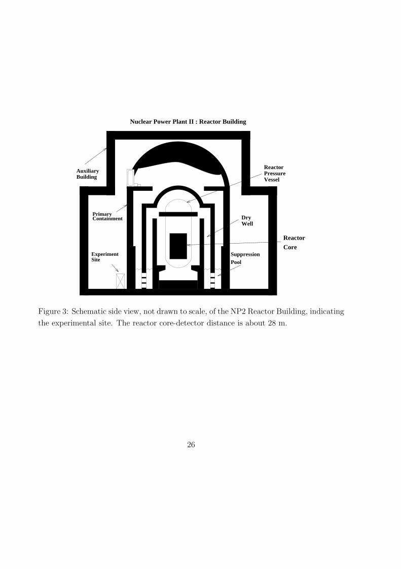
The experiment will be performed at the Nuclear Power Station II at Kuo-sheng at
the northern shore of Taiwan. The experimental location is about 28 m from one of the
reactor cores, and 102 m from the other one. Each of the cores is a boiling water reactor
with 2.9 GW thermal power output, giving a total flux of about 5.6× 1012 cm−2s−1 at the
detector site. The site is at the lowest level of the reactor building, with about 25 mwe
of overburden, as depicted schematically in Figure 3.
To fully exploit the advantageous features of the scintillating crystal approach [3] in
low-energy low-background experiments, the experimental configuration should enable
the definition of a fiducial volume with a surrounding active 4π-veto, and minimal passive
materials.
The schematic design of the experiment is shown in Figure 4. The detector will consist
of about 480 kg of CsI(Tl) crystals4, arranged in a 17 × 15 matrix. One CsI(Tl) crystal
unit consists of a hexagonal-shaped cross-section with 2 cm side and a length 20 cm,
giving a mass of 0.94 kg. Two such units are glued optically at one end to form a module.
The light output are read out at both ends by 29 mm diameter photo-multipliers (PMTs)
with low-activity glass window 5, which provide about 50% of end-surfaces coverage. The
design of the PMT base is optimized for high gain (low threshold) and good linearity over
a large dynamic range. The modular design enables the detector to be constructed in
stages.
Individual crystals are wrapped with 4 layers of 70 µm thick teflon sheets to pro-
vide diffused reflection for optimal light collection. The sum of the two PMT signals
(Qtot = Q1 + Q2) gives the energy of the event, while the difference will provide a mea-
surement of a longitudinal position. Outer layers as well as the last few cm near the
4Manufacturer: Unique Crystals, Beijing5Hamamatsu CR110 customized
8
readout surfaces will be used as active veto. The exact definitions of fiducial and veto
volume can be fine-tuned based on the actual background, and can differ with different
energy ranges.
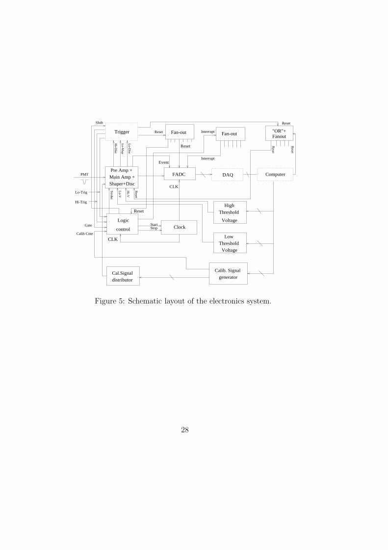
The schematics of the electronics system is depicted in Figure 5. The PMT signals
are fed to amplifiers and shapers, and are finally digitized by 8-bit Flash-Analog-Digital-
Convertor (FADC) modules running at a clock rate of 20 MHz. The shaping is optimized
for the µs time-scale rise and fall times, such that noise-spikes from single photo-electron
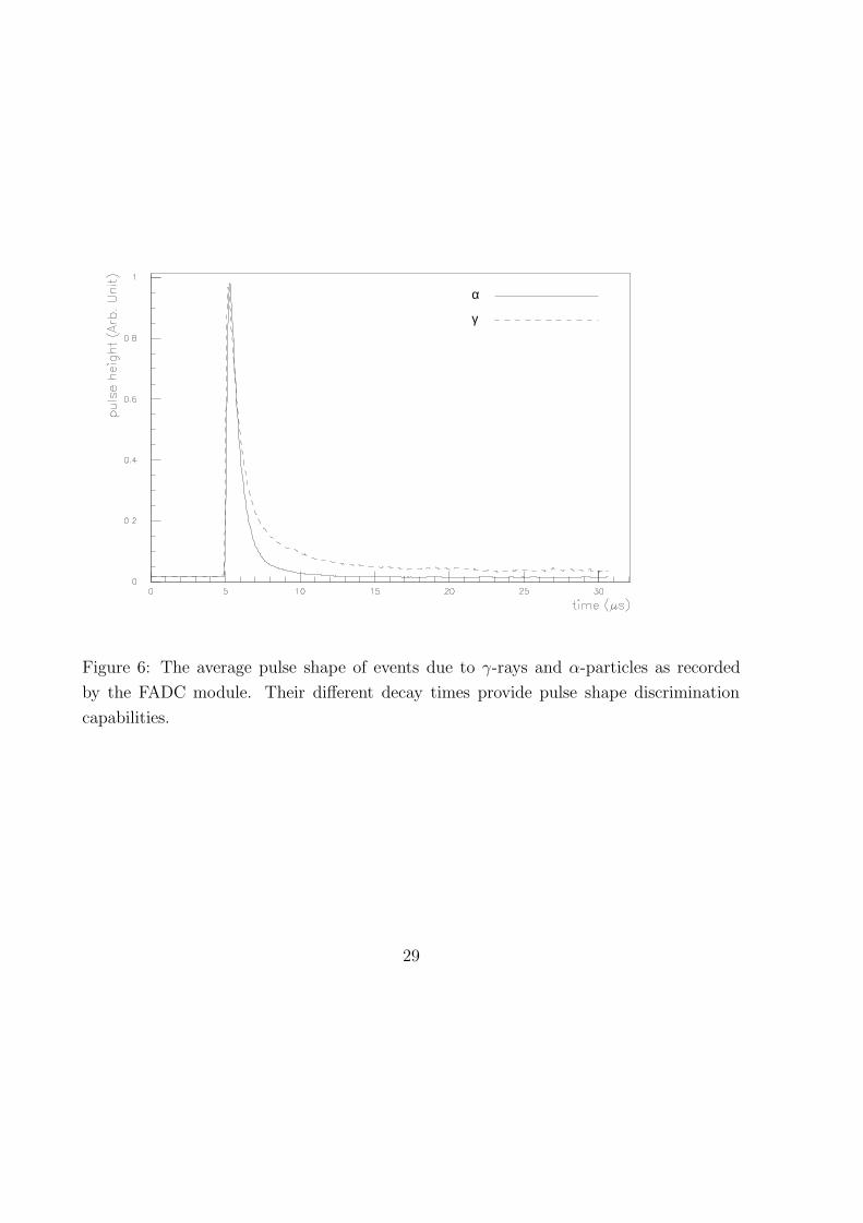
are smeared out and suppressed. Typical scintillation pulses due to γ and α events as
measured by the system are displayed in Figure 6. A precision pulse generator provides
means to calibrate and monitor the performance and stability of the electronics system.
The trigger conditions include: (a) having any one or more channels above a pre-set
“high threshold” (typically 50-100 keV equivalent), and (b) not having a cosmic veto
signal within a previous time-bin of typically 100 µs. Once these conditions are fulfilled,
all channels with signals above a “low threshold” (typically 10-30 keV equivalent) will be
read out. The logic control circuit enables complete acquisition of delayed signatures up
to several ms, to record cascade events in decay series like 238U and 232Th.
The FADC, the trigger units, logic control and calibration modules, are read out
and controlled by a VME-based data acquisition system, connected by a PCI-bus to a PC
running with the LINUX operating system. The on-line and off-line software architecture,
together with their inter-connections, are shown schematically in Figure 7. The on-site
data taking conditions can be remotely monitored from the home-base laboratories via
telephone line. (Internet access to the Nuclear Power Plant is not allowed.) Data will
be saved in hard disks on-site and replaced at the once-per-week interval. They are
duplicated and stored in magnetic tapes and CDs for subsequent off-line analysis. The
detailed design and performance of the electronics, data acquisition and control systems
will be the subject of a forthcoming article.
The compact CsI(Tl) detector enables an efficient shielding to be built. The schematics
of the shielding configuration is depicted in Figure 8. Cosmic-rays and their related
events will be vetoed by an outermost layer of plastic scintillators. The typical veto
gate-time will be ∼100 µs to allow for delayed signatures due to neutron interactions.
Ambient radioactivity is suppressed by 15 cm of lead and 5 cm of steel. The steel layer
also provides the mechanical structures to the system. Neutrons, mostly cosmic-induced
in the lead and steel, are slowed down and then absorbed by 25 cm of boron-loaded
polyethylene. The inner 5 cm of oxygen-free-high-conductivity (OFHC) copper serves
to suppress residual radioactivity from the shielding materials. The copper layers can
9
be dismounted and replaced by more polyethylene, allowing flexibilities to optimize the
shielding conditions with respect to different physics focus. The CsI(Tl) target will be
placed inside a electrically-shielded and air-tight box made of copper sheet. The entire
inner target space will be covered by a plastic bag flushed with dry nitrogen to prevent
the radioactive radon gas from diffusing into the target region.
To enable detector access and maintenance, the entire shielding assembly consists of
three parts: (1) a fixed shielding house, (2) a movable trolley on which the target detector
sits, and (3) the front door which can be moved by wheels. All the access pipes and cable
trays are bent so that there are no direct line-of-sight between the inner target and the
external background. Ports are provided to allow insertion of radiation sources for regular
monitoring and calibration. These ports are blocked by copper plugs during normal data
taking.
5 Performance of Prototype Modules
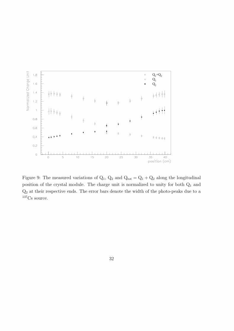
Extensive measurements on the crystal prototype modules have been performed. The
response is depicted in Figure 9, showing the variation of collected light for Q1, Q2 and
Qtot as a function of position within one crystal module. The charge unit is normalized to
unity at the 137Cs photo-peak (660 keV) for both Q1 and Q2 at their respective ends, while
the error bars denote the FWHM width at that energy. The discontinuity at L=20 cm is
due to the optical mis-match between the glue (n=1.5) and the CsI(Tl) crystal (n=1.8).
It can be seen that there is a dependence of Qtot with position at the 10-20% level. A
FWHM energy resolution of 10% is achieved at 660 keV, and its variation with energy
follows the E− 12 relation. The detection threshold (where signals are measured at both
PMTs) is <20 keV. A good linearity of the PMT response is achieved for energies from
20 keV to 20 MeV.
The longitudinal position can be obtained by considering the dimensionless ratio
R = (Q1 −Q2)/(Q1 + Q2), the variation of which at the 137Cs photo-peak energy along
the crystal length is displayed in Figure 10. The ratio of the RMS errors in R relative to
the slope gives the longitudinal position resolutions. The measured resolutions are 2 cm,
3.5 cm and 8 cm at 660 keV, 200 keV and 30 keV, respectively. The dependence of R on
energy is negligible at the less than the 10−3 level.
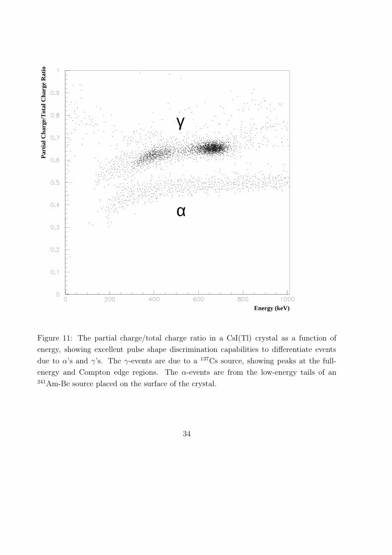
In addition, CsI(Tl) provides powerful pulse shape discrimination (PSD) proper-
ties [39] to differentiate γ/e events from those due to heavily ionizing particles like α’s,
10
which have faster fall time, as shown in Figure 6. The typical separation between α/γ in
CsI(Tl) with the “Partial Charge Vs Total Charge” method [40] is depicted in figure 11,
demonstrating an excellent separation of >99% above 500 keV. Unlike in liquid scintilla-
tors, α’s are only slightly quenched in their light output in CsI(Tl). The quenching factor
depends on the Tl concentration and the measurement parameters like shaping time: for
full integration of the signals, the suppression is typically 50% [13].
6 Background Considerations
6.1 Merits of Crystal Scintillator
The suppression, control and understanding of the background is very important in all
low background experiments. The scintillating crystal detector approach offers several
merits [3] to these ends. The essence are:
I. Large Photon Attenuation:
With its high-Z nuclei, CsI(Tl) provides very good attenuation to γ-rays, especially
at the low energy range below 500 keV. For instance, the attenuation lengths for a
100 keV γ-ray are 0.12 cm and 6.7 cm, respectively, for CsI(Tl) and liquid scintil-
lator. That is, 10 cm of CsI(Tl) has the same attenuating power as 5.6 m of liquid
scintillator at this low energy. Consequently, the effects of external ambient γ back-
ground, like those from the readout device, electronics components, construction
materials and radon diffusion are negligible after several cm of active veto layer.
Therefore, the background at low energy will mostly originate within the fiducial
volume due to the internal components.
For CsI(Tl) which is non-hygroscopic and does not need a hermetic seal system to
operate, “internal components” include only two materials: the crystal itself and
the teflon wrapping sheets, typically at a mass ratio of 1000:1. Teflon is known to
have very high radio-purity (typically better than the ppb level for the 238U and232Th series) [41]. As a result, the experimental challenge becomes much more fo-
cussed - the control and understanding of the internal radio-purity and long-lived
cosmic-induced background of the CsI(Tl) crystal itself.
II. Characteristic Detector Response:
The detection threshold is lower while the energy resolution of CsI(Tl) is better than
typical liquid and plastic scintillator with the same modular mass. Furthermore, in
11
an O(100 kg) CsI(Tl) detector system, the keV-MeV photons originated within
the crystal will be fully captured. These features, together with PSD capabilities
for α-particles and the granularity of the detector design, can provide important
diagnostic tools for understanding the physical processes of the system. Once the
background channels are identified, understood and measured, subtraction of its
associated effects can be performed.
When the dominant background contributions are from internal contaminations, two
complementary strategies can be deployed for the background control : (I) consistent
background subtraction, using the measured spurious α or γ peaks which indicates residual
radioactivity inside the crystal, and (II) the conventional Reactor ON−OFF subtraction.
The background count rate will be stable and not affected by external parameters
such as ambient radon concentrations, details of the surrounding equipment configura-
tions and cosmic veto inefficiencies. Consequently, the systematic uncertainties can be
reduced, and the reliabilities of both background suppression processes will be more ro-
bust. In addition, the large target mass helps to reduce statistical uncertainties. Spectral
shape distribution can also be analyzed to provide additional handles. For instance the
comparison of the signal rates between the “< 1 MeV” and the “> 1 MeV” samples can
enhance the sensitivities in the magnetic moments studies.
6.2 Background Channels
The merits discussed above allow a compact detector design and hence, efficient and cost-
effective shielding configurations. While care and the standard procedures are adopted
for suppressing the ambient radioactivity background (radon purging, choice of clean
construction materials, photon-counting measurements with germanium detectors, use of
PMT with low-activity glass), the key background issue remains that of internal back-
ground from the CsI(Tl) itself. The different contributions and their experimental handles
are discussed below.
6.2.1 Internal Intrinsic Radioactivity
Unlike in liquid scintillators, α’s are only slightly quenched in their light output in CsI(Tl).
Crystals contaminated by uranium or thorium would give rise to multiple peaks above
3 MeV, as reported in Ref. [42]. The absence of multiple peak structures in our prototype
crystals suggest a 238U and 232Th concentration of less than the 10−12 g/g level [∼1 pkd],
12

assuming the decay chains are in equilibrium. In addition, direct counting method with
a high-purity germanium detector shows the 40K and 137Cs contaminations of less than
the 10−10 g/g [∼1700 pkd] and 4 × 10⁻¹⁸ g/g [∼1200 pkd] levels, respectively. Mass
spectrometry method sets limits of 87Ru to less than 8× 10⁻⁹ g/g [∼210 pkd].
Internal radioactivity background typically consists of α, β and γ emissions which
have characteristic energies and temporal-correlations. Residual background below the
measured limits can be identified and subtracted off based on the on-site data. By careful
studies of the timing and energy correlations among the distinct α signatures, precise
information can be obtained on the radioactive contaminants in the cases where the 238U
and 232Th decay series are not in equilibrium, so that the associated β/γ background
can be accounted for accurately. For instance, Dark Matter experiments with NaI(Tl)
reported trace contaminations (range of 10−18 − 10−19 g/g [25-250 pkd] of 210Pb in the
detector, based on γ-peak at 46.5 keV and the equivalent peak for α’s at 5.4 MeV [15,
33]. Accordingly, β-decays from 210Bi can be subtracted off from the signal. Similarly,
the residual β-decays of 40K and 137Cs can be accounted for based on their respective
characteristic γ-lines measure-able from the data.
6.2.2 Cosmic-Induced Radioactivity
The experiment is located at a site with 25 mwe overburden, which is sufficient to ef-
fectively attenuate the primary hadronic component from cosmic rays. The “prompt”
cosmic events can be easily identified, since: (a) the plastic scintillator veto can tag them
at better than 95% efficiency, (b) bremsstrahlung photons from cosmic-rays on the shield-
ings cannot reach the inner fiducial volume of the target, as explained in Section 6.1, (c)
cosmic-induced neutrons, mostly from the lead, are attenuated and absorbed efficiently
by the boron-loaded polyethylene layers, and (d) background originated from cosmic-rays
traversing the CsI(Tl) target will lead to unmistakably large pulses (∼20 MeV for one
crystal).
The more problematic background are due to the long-lived (longer than ms) unstable
isotopes created by the various nuclear interaction processes:
1. Neutron Capture
Ambient neutrons or those produced at the the lead shieldings have little probability
of being captured by the CsI crystal target, being attenuated efficiently by the boron-
loaded polyethylene. Cosmic-induced neutrons (energy range MeV) originated from
13
the target itself have high probability of leaving the target. Residual neutrons can
be captured by the target nuclei 133Cs and 127I predominantly via (n,γ) [43]
n + 133Cs → 134Cs (σ = 30 b ; Q = 6.89 MeV) ;
n + 127I → 128I (σ = 6 b ; Q = 6.83 MeV)
with relatively large cross-sections.
The daughter isotope 134Cs (τ 12
= 2.05 yr ; Q = 2.06 MeV) decays with 70% branch-
ing ratio by beta-decay (end point 658 keV), plus the emission of two γ’s (605 keV
and 796 keV), and therefore will not give rise to a single hit at the low-energy re-
gion. The isotope 128I (τ 12
= 25 min ; Q = 2.14 MeV), on the other hand, has a
branching ratio of 79% having a lone beta-decay, which will mimic the single-hit
signature. The neutron production rate on-site at the CsI(Tl) target is estimated
to be about 50 pkd. Folding in the capture efficiency by the target (∼ 25%) and by127I in particular (∼ 14%), the 128I production rate is about 1.8 pkd.
The neutron capture rate by the CsI target can be measured by tagging γ-bursts
of energy 6.8 MeV. Knowing the capture rate, the contributions to the low-energy
background due to 128I can be evaluated and subtracted off. Furthermore, the
three-fold coincidence from the 134Cs decays can be measured, providing additional
information to the neutron capture rates.
2. Muon Capture
Cosmic-muons can be stopped by the target nuclei and subsequently captured [44]
via
µ− + (A, Z) → (A− Y, Z− 1) + γ ′s + Y neutrons ,
where Y can be 0,1,2,..... with < Y >∼ 1.2. The daughter isotopes for Y=1,2,3 are
all stable, while the Y=0 case (less than 5% probability) will give rise to 133Xe and127Te, both of which can lead to low-energy single-site background events: 133Xe
(τ 12
= 5.3 days ; Q = 428 keV) decays with beta (end-point 347 keV) plus a γ-ray
at 81 keV, while 127Te (τ 12
= 9.4 hr ; Q = 690 keV) decays with a lone beta. The
estimated muon capture rate on-site at the CsI target is ∼30 pkd, so that the
background contributions from the Y=0 channels are less than 1.5 pkd.
3. Muon-Induced Nuclear Dissociation
Cosmic-muons can disintegrate the target nuclei via the (γ,n) interactions or by
spallations [45], at an estimated rate of ∼10 pkd and ∼1 pkd, respectively. Among
14
the various decay configurations of the final states nuclei of the (γ,n) processes,132Cs and 126I, only about 20% (or ∼2 pkd) of the cases will give rise to single-
hit background. The other decays give characteristic and identifiable signatures.
For instance, 132Cs decays by electron capture resulting in the emissions of a γ-ray
at 668 keV plus the X-rays from xenon. These can easily be tagged and used as
reference to subtract the single-hit background.
6.2.3 Reactor-ON Correlated Background
Previous experiments with reactor neutrinos [6] as well as on-site measurements indicate
that γ and neutron background associated with “reactor-ON” are essentially zero outside
the reactor core and within reasonable shieldings. The target region is proton-free and
therefore neutrino-induced background from νe-p is negligible. These interactions, how-
ever, will occur at the polyethylene shieldings. The prompt e+ will only give rise at most
to 511 keV γ-rays, while the neutron (energy range 1-10 keV) will be mostly captured
by the 10B in the polyethylene, producing only 480 keV γ-rays. Both of these low energy
γ-background will be efficiently attenuated by the copper shielding and the active veto.
6.3 Sensitivity Goals
From the various background considerations discussed in the previous sections, it can be
seen that while the background control is non-trivial like all other low-energy neutrino
experiments, there are more experimental handles to suppress and identify them with
the crystal scintillator approach. The efficient γ-peak detection, the fine granularity and
the PSD capabilities of the CsI(Tl) detector provides enhanced analyzing and diagnostic
power for the background understanding. The dominating contribution to the sensitivities
is due to the internal background in the CsI(Tl) target. The experimental challenge is
focussed and therefore more elaborate procedures can be deployed to study and enhance
the radio-purity of this one material as the experiment evolves.
The present studies place limits on internal radio-purity to the range of less than the
1000 pkd level. Residual contaminations, if exist, can be further studied and measured
by various methods like photon counting with germanium detectors, neutron activation
analysis, mass spectroscopy analysis, as well as by the spectroscopic and time-correlation
input from on-site data taking. The effects due to cosmic-induced long-lived isotopes are
typically at the range of a few pkd. Background due to both channels can be reduced
15
by consistent background subtraction when the sources are identified and measured, and
the goal of a suppression factor of 102 can be achieve-able. Such background subtraction
strategies have been successfully used in accelerator neutrino experiments. As an illustra-
tion, the CHARM-II experiment measured about 2000 neutrino-electron scattering events
from a sample of candidate events with a factor of 20 larger in size [49]. Events due to
the various background processes were identified and subtracted off, such that a few %
uncertainty in the signal rate had been achieved.
It can be seen from Figure 2b that a Standard Model rate of∼1 pkd can be expected for
a detection threshold of 100 keV. After performing the consistent background suppression,
a residual Background-to-Signal ratio of less than 10 before Reactor ON−OFF subtraction
is realistic. Therefore, based on Reactor ON/OFF periods of 100 and 50 days, respectively,
a fiducial mass of 300 kg of CsI(Tl) target, and a detector systematic uncertainty of 1%
in performing the Reactor ON−OFF subtraction, the sensitivity goals of 3× 10⁻¹¹ µB for
the magnetic moment search and a 5-10% uncertainty to the cross-section measurements
can be projected. A comparison with previous on-going experiments is summarized in
Table 2.
Under similar assumptions, an event rate of >0.005 pkd can be observed for the νe-
NCEX channel of the various candidate lines in the 50-500 keV range, corresponding to
the cross-section sensitivities of ∼ 2× 10−45cm2.
7 Status and Prospects
By the end of 1999, the design and prototype studies of the experiment have been com-
pleted. Construction is intensely underway. A complete 100-kg system, with full elec-
tronics and shieldings, is expected to be installed on-site at the Reactor Plant by summer
2000. Date taking will commence while the second 100-kg system will be added in phase.
Future upgrades and modifications of the experiment will depend on the first results, with
the goals of achieving a 500 kg system eventually.
The detector design adopted in this experiment can be adopted for other low-energy
low-background experiments based on scintillating crystal detectors [3], such as Dark
Matter WIMP searches [15, 32], sub-MeV Solar Neutrino detection (indium-loaded [46],
LiI(Eu) [31] or GSO [47] crystals have been proposed), and further studies of νe-NCEX on
other isotopes like 7Li, 10B and 11B [30, 35]. Experience and results from the the reactor
neutrino experiment with CsI(Tl) crystals reported in this work will provide valuable
16
input to these projects.
Much flexibility is available for detector optimization based on this generic and easily
scale-able design. Different modules can be made of different crystals. More and longer
crystals can be glued to form one module. Different crystals can be glued together, in
which case the event location among the various crystals can be deduced from the different
pulse shape. Passive target can be inserted to replace a crystal module. New wrapping
materials can be used instead of teflon − there is an interesting new development with
sol-gel coating which can be as thin as a few microns [48], thereby even reducing the
passive materials within the fiducial volume further.
The authors are grateful to the technical staff of their institutes for the invaluable
support, and to the CYGNUS Collaboration for the loan of the veto plastic scintillators.
This work was supported by contracts NSC 87-2112-M-001-034 and NSC 88-2112-M-001-
007 from the National Science Council, Taiwan, as well as NSF 01-5-23336 and NSF 01-
5-23374 from the National Science Foundation, U.S.A.
17
References
[1] For a recent review on the crystal scintillator detector, see, for example,
M. Ishii and M. Kobayashi, Prog. Crystal Growth and Charact., 23, 245 (1991), and
references therein.
[2] For a recent review on the applications of crystal scintillator in particle physics, see,
for example
G. Gratta, H. Newman, and R.Y. Zhu, Ann. Rev. Nucl. Part. Sci. 44, 453 (1994).
[3] H.T. Wong et al., hep-ex/9910002, submitted to Astropart. Phys.
[4] H..T. Wong and J. Li, Nucl. Phys. B (Proc. Suppl.) 77, 177 (1999)
[5] For a recent review on experiments on high energy neutrino interactions, see, for
example,
J.M. Conrad, M.H. Shaevitz and T. Bolton, Rev. Mod. Phys. 70, 1341 (1998).
[6] G. Zacek et al., Phys. Rev. D 34, 2621 (1986) ;
A.I. Afonin et al., Sov. Phys. JETP 67 (2), 213 (1988);
G.S. Vidyakin et al., JETP Lett. 59, 364 (1994);
B. Achkar et al., Nucl. Phys. B 434, 503 (1995);
Z.D. Greenwood et al., Phys. Rev. D 53, 6054 (1996);
M. Apollonio et al., Phys. Lett. B 420, 397 (1998);
F. Boehm et al., Palo Verde Proposal (1993).
[7] B. Achkar et al., Bugey Collaboration, Phys. Lett. B 374, 243 (1996).
[8] F. Reines, H.S. Gurr and H.W. Sobel, Phys. Rev. Lett. 37, 315 (1976).
[9] G.S. Vidyakin et al, JETP Lett. 55, 206 (1992).
[10] A.I. Derbin et al., JETP Lett. 57, 769 (1993).
[11] T.L. Jenkins, F.E. Kinard, and F. Reines, Phys. Rev. 185, 1599 (1969); E. Pasierb
et al., Phys. Rev. Lett. 43, 96 (1979);
G.S. Vidyakin et al., JETP Lett. 49, 151 (1988); G.S. Vidyakin et al., JETP Lett.
51, 279 (1990);
S.P. Riley et al., Phys. Rev. C 59, 1780 (1999).
18
[12] Letter of Intent, Belle Coll., KEK (1993);
Letter of Intent, BaBar Coll., SLAC-443 (1994).
[13] H. Grassman, E. Lorentz, and H.G. Moser, Nucl. Instrum. Methods 228, 323 (1985);
P. Schotanus, R. Kamermans, and P. Dorenbos, IEEE Trans. Nucl. Sci. 37, 177
(1990).
[14] D.E. Groom, Nucl. Instrum. Methods 219, 141 (1984);
S. Gunji et al., Nucl. Instrum. Methods A 295, 400 (1990);
M. Suffert, Nucl. Instrum. Methods A 322, 523 (1992).
[15] K. Fushimi et al., Phys. Rev. C 47, R425 (1993);
M.L. Sarsa et al., Nucl. Phys. B 35, 154 (1994);
N.J.C. Spooner et al., Phys. Lett. B 321, 156 (1994);
R. Bernabei et al., Phys. Lett. B 450, 448 (1999);
G. Gerbier et al., Astropart. Phys. 11, 287 (1999).
[16] A.V. Kyuldjiev, Nucl. Phys. B 243, 387 (1984).
[17] P.Vogel and J.Engel, Phys. Rev. D 39, 3378 (1989).
[18] B. Kayser et al., Phys. Rev. D 20, 87 (1979).
[19] R.C. Allen et al., Phys. Rev. Lett. 55, 2401 (1985);
R.C. Allen et al., Phys. Rev. D 47, 11 (1993).
[20] For a recent review on solar neutrino experiments, see, for example,
R.E. Lanou Jr., Nucl. Phys. B (Procs. Suppl.) 77, 55 (1999).
[21] L. Wolfenstein, Phys. Rev. D 17, 2369 (1978);
S.P. Mikheyev and A. Yu. Smirnov, Sov. J. Nucl. Phys. 42, 1441 (1985).
[22] C. Broggini et al., Nucl. Instrum. Methods A311, 319 (1992);
C. Amsler et al., Nucl. Instrum. Methods A 396, 115 (1997).
[23] J.M. Lattimer and J. Cooperstein, Phys. Rev. Lett. 61, 23 (1988);
R. Barbieri and R.N. Mohapatra, Phys. Rev. Lett. 61 27 (1988);
D. Notzold, Phys. Rev. D 38, 1658 (1988).
[24] J. Bernstein et al., Phys. Rev. 132, 1277 (1963);
P. Sutherland et al., Phys. Rev. D 12, 2700 (1976);
G. Raffelt, Phys. Rev. Lett. 64, 2856 (1990).
19
[25] J. Morgan, Phys. Lett. B 102, 247 (1981);
M. Fukugita and S. Yazaki, Phys. Rev. D 37, 3817 (1987).
[26] M.B. Voloshin, M.I. Vysotskii and L.B. Okun, Sov. Phys. JETP 64, 446 (1986).
[27] I.R. Barabanov et al., Astropart. Phys. 5, 159 (1996);
A.G. Beda et al., LANL preprint hep-ex/9706004 (1997).
[28] B. Armbruster et al., Phys. Lett. B 423, 15 (1998).
[29] H.C. Lee, Nucl. Phys. A 294, 473 (1978) ;
T.W. Donnelly and R.D. Reccei, Phys. Rep. 50, 1 (1979).
[30] R.S. Raghavan and S. Pakvasa, Phys. Rev. D 37, 849 (1988).
[31] C.C. Chang, C.Y. Chang, and G. Collins, Nucl. Phys. (Proc. Suppl.) B 35, 464
(1994).
[32] M.W. Goodman and E. Witten, Phys. Rev. D 31, 3059 (1985);
J. Ellis, R.A. Flores and J.D. Lewin, Phys. Lett. B 212, 375 (1988).
[33] H. Ejiri, K. Fushimi and H. Ohsumi, Phys. Lett. B 317, 14 (1993).
[34] P. Belli et al., Phys. Lett. B 387, 222 (1996).
[35] D.B. Kaplan and A. Manohar, Nucl. Phys. B 310,527 (1988);
J. Bernabeu et al., Nucl. Phys. B 378, 131 (1992);
G. Garvey et al., Phys. Rev. C 48, 1919 (1993);
K. Kubodera and S. Nozawa, Int. J. Mod. Phys. E 3, 101 (1994).
[36] ORLaND Proposal (1998).
[37] L.M. Krauss, S.L. Glashow and D.N. Schramm, Nature 310, 191 (1984).
[38] C.Y. Chang, S.C. Lee and H.T. Wong, Nucl. Phys. B (Procs. Suppl.) 66, 419 (1998).
[39] J. Alarja et al., Nucl. Instrum. Methods A 242, 352 (1986);
P. Kreutz et al., Nucl. Instrum. Methods A 260, 120 (1987).
[40] C.L. Morris et. al., Nucl. Instrum. Methods 137, 397 (1976);
M.S. Zucker and N. Tsoupas, Nucl. Instrum. Methods A299, 281 (1990).
[41] P. Jagam and J.J. Simpson, Nucl. Instrum. Methods A 324,
20
[42] U. Kilgus, R. Kotthaus, and E. Lange, Nucl. Instrum. Methods A 297, 425, (1990);
R. Kotthaus, Nucl. Instrum. Methods A 329, 433 (1993).
[43] V.L. Alexeev et al., Nucl. Phys. A248, 249 (1975);
L.A. Schaller, J. Kern and B. Michaud, Nucl. Phys. A 165, 415 (1971).
[44] S. Charalambus, Nucl. Phys. A 166, 145 (1971);
T. Suzuki, D.F. Measday, and J.P. Roalsvig, Phys. Rev. C 35, 2212 (1987);
T. Kozlowski et al., Nucl. Phys. A 436, 717 (1985).
[45] G. Cocconi and V. Cocconi Tongiorgi, Phys. Rev 84, 29 (1951);
S. Hayakawa, Phys. Rev 84, 37 (1951).
[46] R.S. Raghavan, Phys. Rev. Lett. 37, 259 (1976);
M. Avenier et al., Nucl. Phys. B (Proc. Suppl.) 28A, 496 (1992).
[47] R.S. Raghavan, Phys. Rev. Lett. 78, 3618 (1997).
[48] R. Chipaux et al., DAPNIA-SED-98-01, to be published in IEEE Trans Nucl. Sci.
(1999).
[49] P. Vilain et al., Phys. Lett. B 335, 246 (1994).
21
Properties CsI(Tl) NaI(Tl) BGO Liquid Plastic
Density (gcm−3) 4.51 3.67 7.13 0.9 1.0
Relative Light Yield 0.45 1.00 † 0.15 0.4 0.35
Radiation Length (cm) 1.85 2.59 1.12 ∼45 ∼45
dE/dx for MIP (MeVcm−1) 5.6 4.8 9.2 1.8 1.9
Emission Peak (nm) 565 410 480 425 425
Decay Time (ns) 1000 230 300 2 2
Refractive index 1.80 1.85 2.15 1.5 1.6
Hygroscopic slightly yes no no no
† Typical light yield for NaI(Tl) is about 40000 photons per MeV.
Table 1: Characteristic properties of the common crystal scintillators and their comparison
with typical liquid and plastic scintillators.
22
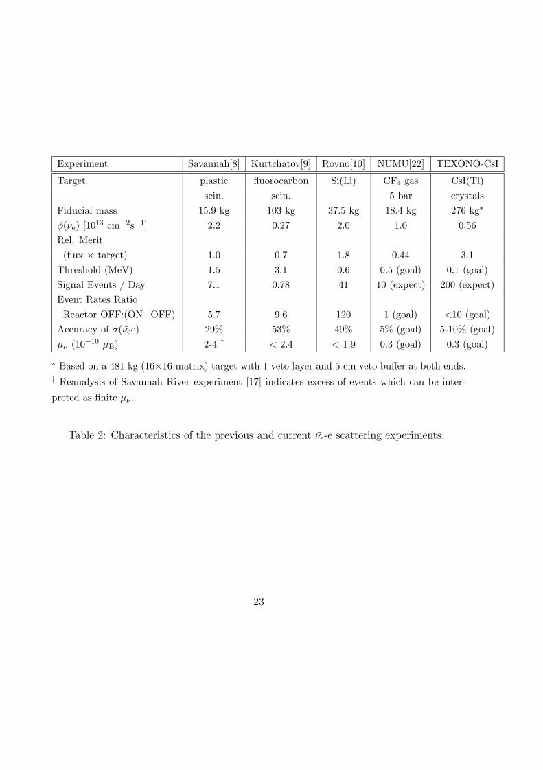
Experiment Savannah[8] Kurtchatov[9] Rovno[10] NUMU[22] TEXONO-CsI
Target plastic fluorocarbon Si(Li) CF4 gas CsI(Tl)scin. scin. 5 bar crystals
Fiducial mass 15.9 kg 103 kg 37.5 kg 18.4 kg 276 kg∗
φ(νe) [1013 cm−2s−1] 2.2 0.27 2.0 1.0 0.56Rel. Merit(flux × target) 1.0 0.7 1.8 0.44 3.1
Threshold (MeV) 1.5 3.1 0.6 0.5 (goal) 0.1 (goal)Signal Events / Day 7.1 0.78 41 10 (expect) 200 (expect)Event Rates RatioReactor OFF:(ON−OFF) 5.7 9.6 120 1 (goal) <10 (goal)
Accuracy of σ(νee) 29% 53% 49% 5% (goal) 5-10% (goal)µν (10−10 µB) 2-4 † < 2.4 < 1.9 0.3 (goal) 0.3 (goal)
∗ Based on a 481 kg (16×16 matrix) target with 1 veto layer and 5 cm veto buffer at both ends.† Reanalysis of Savannah River experiment [17] indicates excess of events which can be inter-
preted as finite µν .
Table 2: Characteristics of the previous and current νe-e scattering experiments.
23

sin2θW
Figure 1: Sensitivities of typical (νµ e), (νµ e), (νe e) and (νe e) cross-section measurements
to the different regions in the gA-gV parameter space, showing their complementarity. The
Standard Model values are denoted by the black dot.
24
(a)
(b)
Figure 2: (a) Differential cross section showing the electron recoil energy spectrum in
νe-e scatterings, and (b) expected event rates as a function of the detection threshold of
the recoil electrons, at a reactor neutrinos flux of 1013 cm−2s−1, for the Standard Model
processes and for the contribution due to a neutrino magnetic moment of 10−10 Bohr
magneton.
25
ExperimentSite
PrimaryContainment
BuildingAuxiliary
ReactorPressureVessel
DryWell
SuppressionPool
Nuclear Power Plant II : Reactor Building
Reactor
Core
Figure 3: Schematic side view, not drawn to scale, of the NP2 Reactor Building, indicating
the experimental site. The reactor core-detector distance is about 28 m.
26
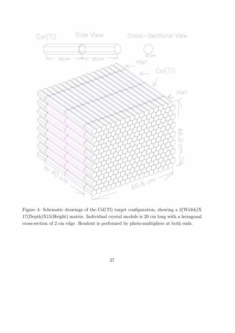
Figure 4: Schematic drawings of the CsI(Tl) target configuration, showing a 2(Width)X
17(Depth)X15(Height) matrix. Individual crystal module is 20 cm long with a hexagonal
cross-section of 2 cm edge. Readout is performed by photo-multipliers at both ends.
27
FADC
HighThreshold
Voltage
LowThreshold
Voltage
generator
Clock
"OR"+FanoutFan-outFan-out
Start
CLK
Event
Pre Amp +
Shaper+DiscMain Amp + ComputerDAQ
Trigger
Stop
CLK
PMT
GateLogic
control
Cal.Signaldistributor
Reset
Lo-D
isc
Reset
Hi-Trig
Lo-Trig
Calib Cnte
Lo-V
Strobe
Reset
Hi-V
Reset
Reset
Calib. Signal
Shift
Lo-M
ap
Hi-D
isc
Reset Interrupt
Interrupt
Reset
Figure 5: Schematic layout of the electronics system.
28
α
γ
Figure 6: The average pulse shape of events due to γ-rays and α-particles as recorded
by the FADC module. Their different decay times provide pulse shape discrimination
capabilities.
29

Slow control: PC
DOSWIN95
LINUX
HV
LeCroy 1458
LVstemp. flow
etc
HD
HD
HD
Physics Analysis
VME bus
...etc
FADC, Calibration, Clock,
Ethernet
On-Site Off-SIte
Monitoring
CD
TAPE
LINUX HD
HD
HD
Raw
Data
Farm
PC-VME connector
online monitoring: PC
Ethernet
OfflineDataFarm
TAPE
CD
Telephone line
Portable HD
Offline Data Process
Channel/Event FilterData refinement/calibrationStored as Ntuples
Pulse shape rebuilt
OnlineOffline
PC
and electronic
To detector
Figure 7: Schematic layout of the data acquisition and on-line monitoring systems, and
its interfacing with the off-line software packages. A telephone line provides connection
from home-base laboratories to the experimental site in the reactor building.
30
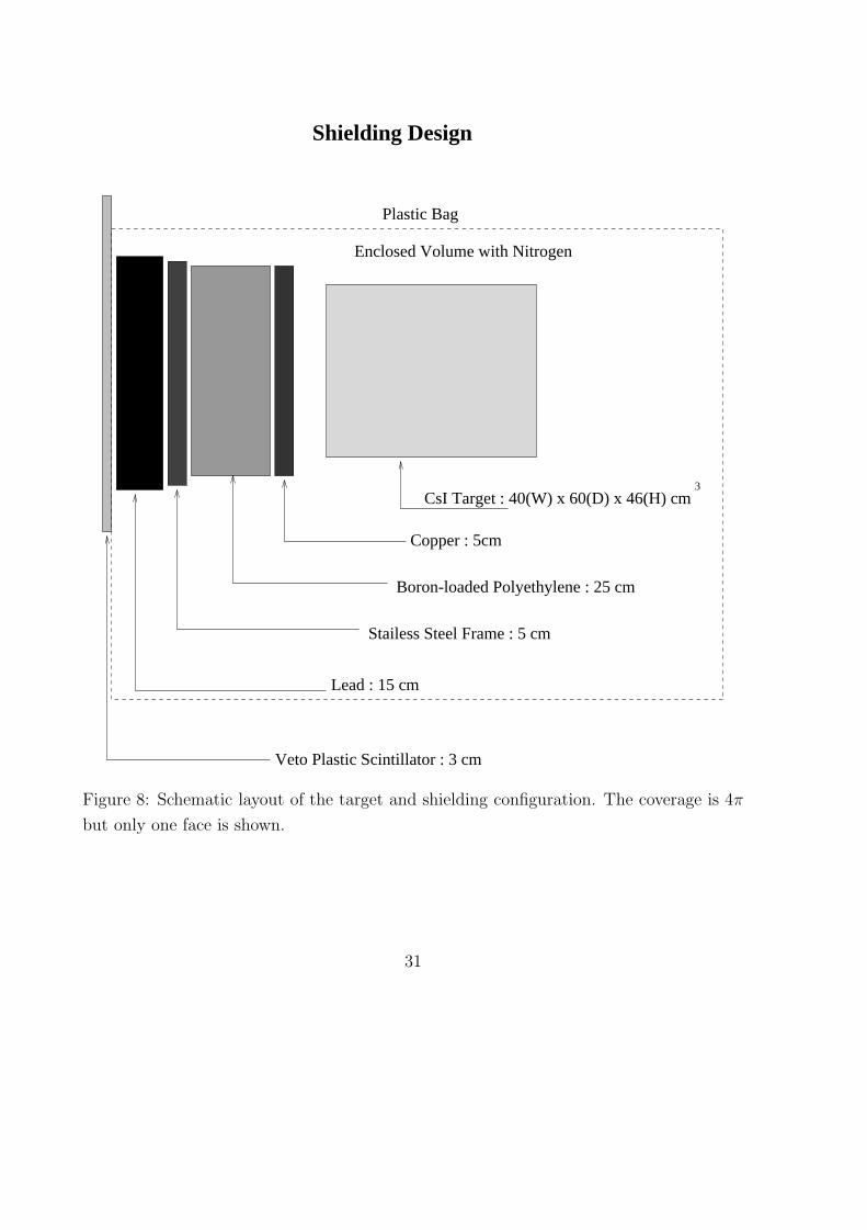
CsI Target : 40(W) x 60(D) x 46(H) cm3
Copper : 5cm
Stailess Steel Frame : 5 cm
Lead : 15 cm
Veto Plastic Scintillator : 3 cm
Shielding Design
Enclosed Volume with Nitrogen
Plastic Bag
Boron-loaded Polyethylene : 25 cm
Figure 8: Schematic layout of the target and shielding configuration. The coverage is 4π
but only one face is shown.
31
Q1
Q2
Q1+Q2
Figure 9: The measured variations of Q1, Q2 and Qtot = Q1 + Q2 along the longitudinal
position of the crystal module. The charge unit is normalized to unity for both Q1 and
Q2 at their respective ends. The error bars denote the width of the photo-peaks due to a137Cs source.
32
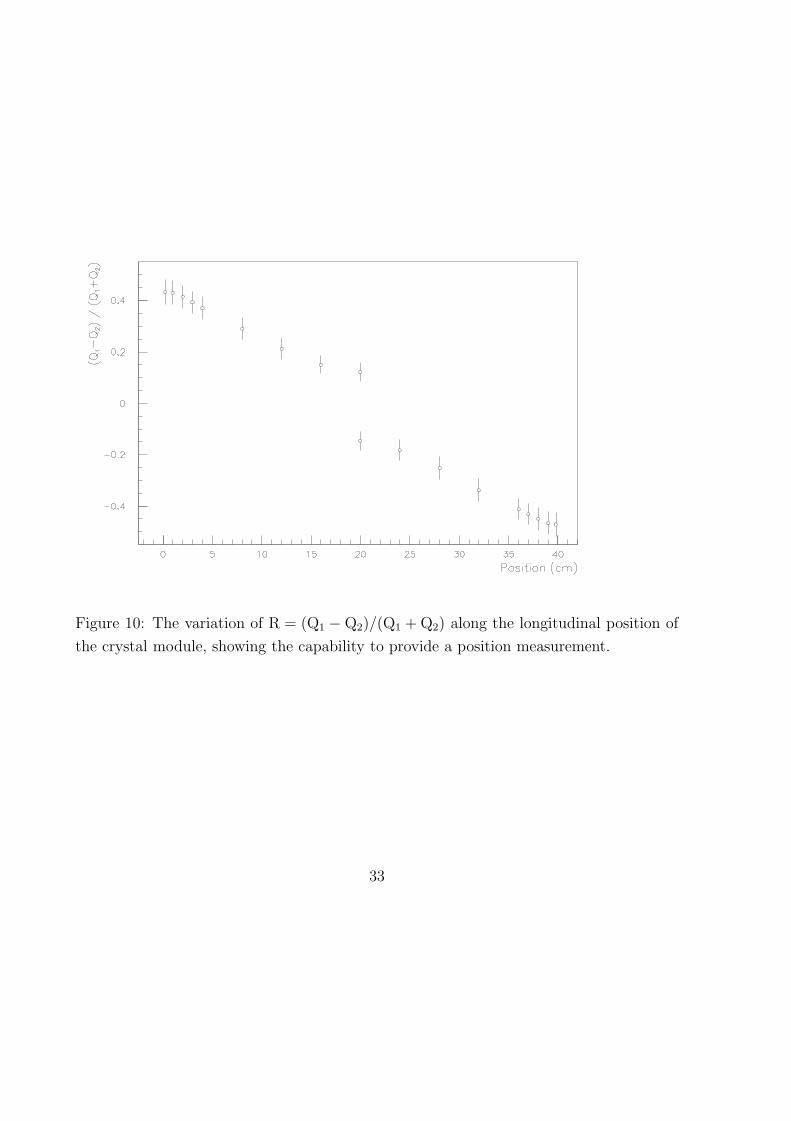
Figure 10: The variation of R = (Q1 −Q2)/(Q1 + Q2) along the longitudinal position of
the crystal module, showing the capability to provide a position measurement.
33
Par
tial C
harg
e/T
otal
Cha
rge
Rat
io
Energy (keV)
α
γ
Figure 11: The partial charge/total charge ratio in a CsI(Tl) crystal as a function of
energy, showing excellent pulse shape discrimination capabilities to differentiate events
due to α’s and γ’s. The γ-events are due to a 137Cs source, showing peaks at the full-
energy and Compton edge regions. The α-events are from the low-energy tails of an241Am-Be source placed on the surface of the crystal.
34


![K. Scholberg, Duke University On behalf of the COHERENT ... · CsI[Na] Scintillating Crystal 14.6 20 6.5 Ge HPGe PPC 10 22 5 LAr Single-phase 22 29 20 NaI[Tl] Scintillating crystal](https://static.fdocuments.in/doc/165x107/5f2d0a7dca764506c44b2161/k-scholberg-duke-university-on-behalf-of-the-coherent-csina-scintillating.jpg)