
A Comparison of Supercritical Carbon Dioxide Power Cycle ... · PDF fileA Comparison of...
14
NREL is a national laboratory of the U.S. Department of Energy, Office of Energy Efficiency and Renewable Energy, operated by the Alliance for Sustainable Energy, LLC. A Comparison of Supercritical Carbon Dioxide Power Cycle Configurations with an Emphasis on CSP Applications 2013 SolarPACES Las Vegas, NV September 19, 2013 Ty Neises, NREL [email protected] NREL/PR-5500-60654
Transcript of A Comparison of Supercritical Carbon Dioxide Power Cycle ... · PDF fileA Comparison of...

NREL is a national laboratory of the U.S. Department of Energy, Office of Energy Efficiency and Renewable Energy, operated by the Alliance for Sustainable Energy, LLC.
A Comparison of Supercritical Carbon Dioxide Power Cycle Configurations with an Emphasis
on CSP Applications
2013 SolarPACES Las Vegas, NV September 19, 2013 Ty Neises, NREL [email protected]
NREL/PR-5500-60654
NATIONAL RENEWABLE ENERGY LABORATORY
Supercritical Carbon Dioxide Background
2
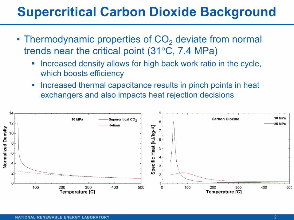
• Thermodynamic properties of CO2 deviate from normal trends near the critical point (31°C, 7.4 MPa) Increased density allows for high back work ratio in the cycle,
which boosts efficiency Increased thermal capacitance results in pinch points in heat
exchangers and also impacts heat rejection decisions
NATIONAL RENEWABLE ENERGY LABORATORY
Attractive Features of s-CO2 Brayton Cycle
3
• Simpler cycle design than steam Rankine • Potentially achieves higher efficiency than steam Rankine • High density working fluid yields compact turbomachinery • Viable turbine designs from 10 to 300 MWe • Low-cost, low-toxicity, low-corrosivity fluid; thermally
stable at temperatures of interest to CSP (550°C to 750°C)
• Single phase reduces operational complexity; integrates well with sensible heat storage in CSP systems
• Multiple high-efficiency cycle configurations possible to match to a specific application
NATIONAL RENEWABLE ENERGY LABORATORY
Considerations for CSP Integration
4
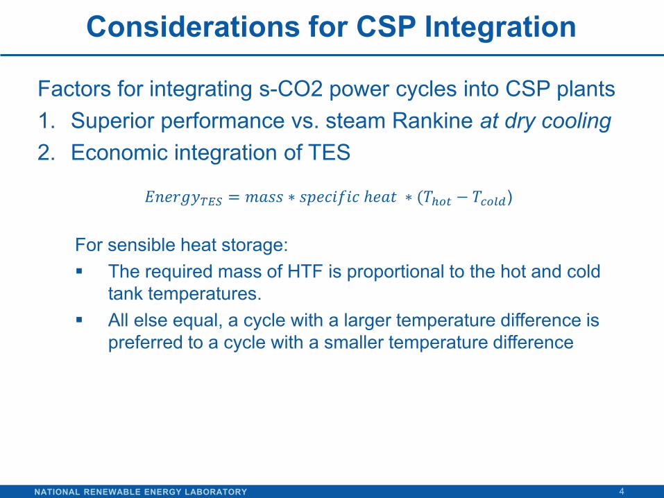
Factors for integrating s-CO2 power cycles into CSP plants 1. Superior performance vs. steam Rankine at dry cooling 2. Economic integration of TES
For sensible heat storage: The required mass of HTF is proportional to the hot and cold
tank temperatures. All else equal, a cycle with a larger temperature difference is
preferred to a cycle with a smaller temperature difference
𝐸𝐸𝐸𝐸𝐸𝑦𝑇𝑇𝑇 = 𝑚𝑚𝑚𝑚 ∗ 𝑚𝑠𝐸𝑠𝑠𝑠𝑠𝑠 ℎ𝐸𝑚𝑒 ∗ (𝑇ℎ𝑜𝑜 − 𝑇𝑐𝑜𝑐𝑐)
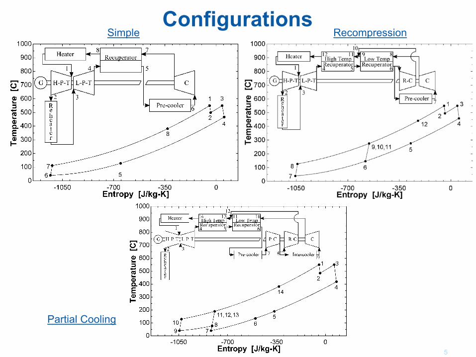
Configurations
5
Partial Cooling
Simple Recompression
NATIONAL RENEWABLE ENERGY LABORATORY
Modeling Background and Research Objective
6
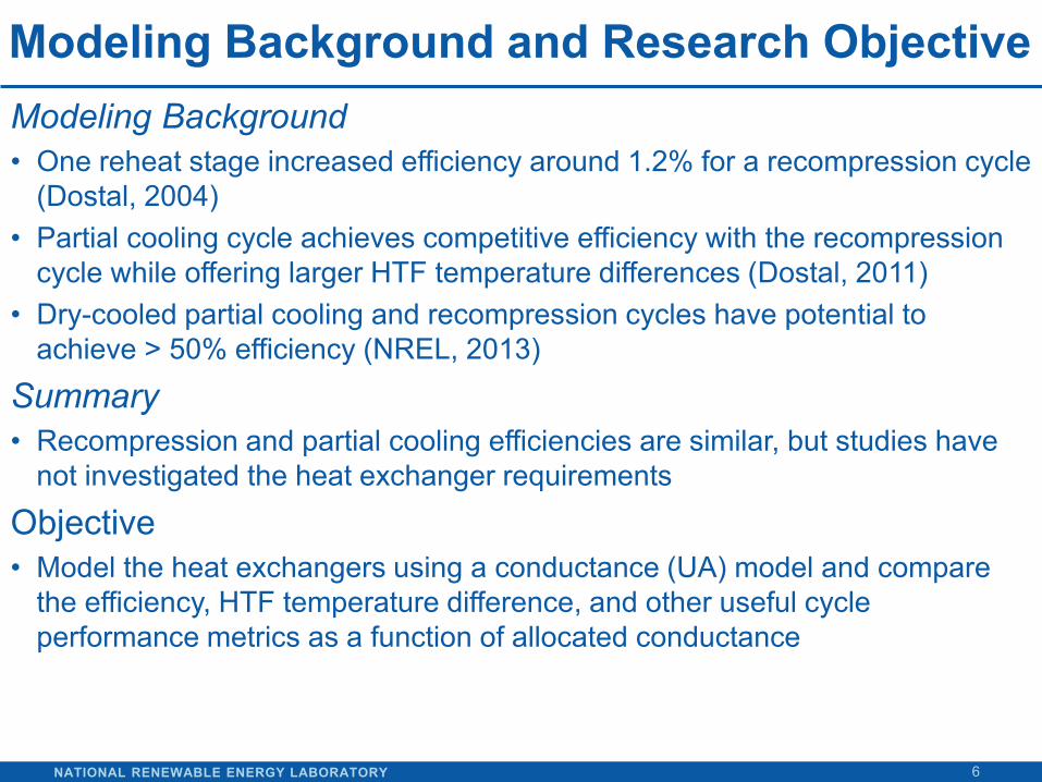
Modeling Background • One reheat stage increased efficiency around 1.2% for a recompression cycle
(Dostal, 2004) • Partial cooling cycle achieves competitive efficiency with the recompression
cycle while offering larger HTF temperature differences (Dostal, 2011) • Dry-cooled partial cooling and recompression cycles have potential to
achieve > 50% efficiency (NREL, 2013)
Summary • Recompression and partial cooling efficiencies are similar, but studies have
not investigated the heat exchanger requirements
Objective • Model the heat exchangers using a conductance (UA) model and compare
the efficiency, HTF temperature difference, and other useful cycle performance metrics as a function of allocated conductance
NATIONAL RENEWABLE ENERGY LABORATORY
Recuperator Modeling Approaches
7
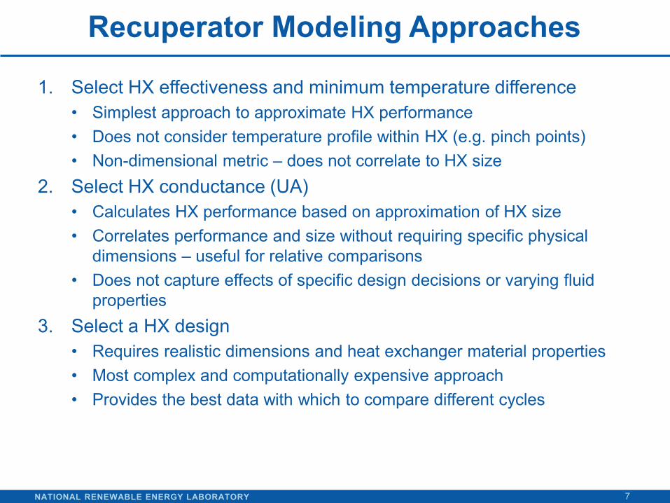
1. Select HX effectiveness and minimum temperature difference • Simplest approach to approximate HX performance • Does not consider temperature profile within HX (e.g. pinch points) • Non-dimensional metric – does not correlate to HX size
2. Select HX conductance (UA) • Calculates HX performance based on approximation of HX size • Correlates performance and size without requiring specific physical
dimensions – useful for relative comparisons • Does not capture effects of specific design decisions or varying fluid
properties 3. Select a HX design
• Requires realistic dimensions and heat exchanger material properties • Most complex and computationally expensive approach • Provides the best data with which to compare different cycles
NATIONAL RENEWABLE ENERGY LABORATORY
Design and Optimized Parameters for Case Studies
8
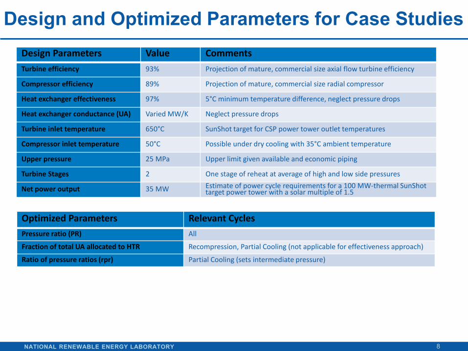
Design Parameters Value Comments Turbine efficiency 93% Projection of mature, commercial size axial flow turbine efficiency
Compressor efficiency 89% Projection of mature, commercial size radial compressor
Heat exchanger effectiveness 97% 5°C minimum temperature difference, neglect pressure drops
Heat exchanger conductance (UA) Varied MW/K Neglect pressure drops
Turbine inlet temperature 650°C SunShot target for CSP power tower outlet temperatures
Compressor inlet temperature 50°C Possible under dry cooling with 35°C ambient temperature
Upper pressure 25 MPa Upper limit given available and economic piping
Turbine Stages 2 One stage of reheat at average of high and low side pressures
Net power output 35 MW Estimate of power cycle requirements for a 100 MW-thermal SunShot target power tower with a solar multiple of 1.5
Optimized Parameters Relevant Cycles Pressure ratio (PR) All
Fraction of total UA allocated to HTR Recompression, Partial Cooling (not applicable for effectiveness approach)
Ratio of pressure ratios (rpr) Partial Cooling (sets intermediate pressure)
NATIONAL RENEWABLE ENERGY LABORATORY
Results – Recuperator Effectiveness Model
9
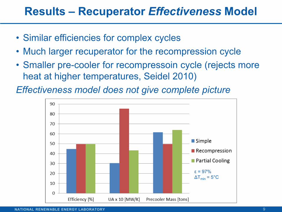
• Similar efficiencies for complex cycles • Much larger recuperator for the recompression cycle • Smaller pre-cooler for recompressoin cycle (rejects more
heat at higher temperatures, Seidel 2010) Effectiveness model does not give complete picture
ε = 97% ΔTmin = 5°C
NATIONAL RENEWABLE ENERGY LABORATORY
Results – Recuperator Conductance Model
10
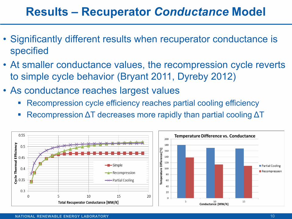
• Significantly different results when recuperator conductance is specified
• At smaller conductance values, the recompression cycle reverts to simple cycle behavior (Bryant 2011, Dyreby 2012)
• As conductance reaches largest values Recompression cycle efficiency reaches partial cooling efficiency Recompression ΔT decreases more rapidly than partial cooling ΔT
NATIONAL RENEWABLE ENERGY LABORATORY
Modeling Limitations
11
• Neglecting pressure drops Larger pressure difference in partial cooling cycle Lower densities in partial cooling cycle may require more or
larger channels
• Conductance HX model does not consider the impact of absolute pressures and pressure differentials
• Does not consider impact of varying fluid properties on heat transfer coefficients
• Pre-cooler model is not optimized with the cycle design Trade-offs between cycle efficiency, pre-cooler size, and fan
parasitics should be considered
NATIONAL RENEWABLE ENERGY LABORATORY
Integration with Direct CO2 Receivers
12
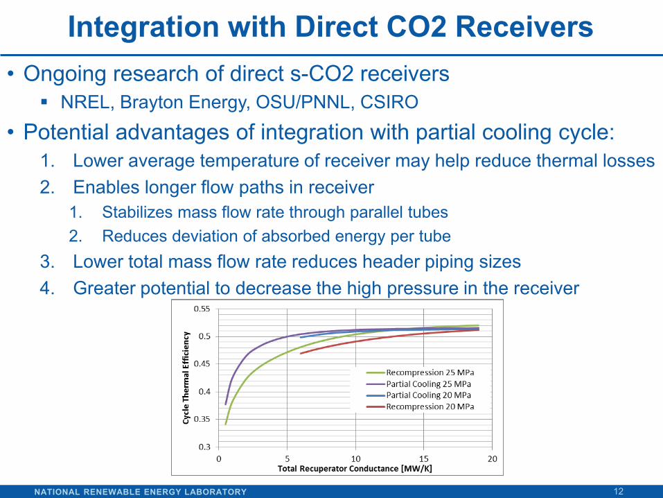
• Ongoing research of direct s-CO2 receivers NREL, Brayton Energy, OSU/PNNL, CSIRO
• Potential advantages of integration with partial cooling cycle: 1. Lower average temperature of receiver may help reduce thermal losses 2. Enables longer flow paths in receiver
1. Stabilizes mass flow rate through parallel tubes 2. Reduces deviation of absorbed energy per tube
3. Lower total mass flow rate reduces header piping sizes 4. Greater potential to decrease the high pressure in the receiver
NATIONAL RENEWABLE ENERGY LABORATORY
Conclusions
13
• Using a conductance model for the recuperator provides a more equivalent comparison than an effectiveness model
• The partial cooling cycle outperforms the recompression cycle until large quantities of conductance are modeled
• The partial cooling cycle offers a larger temperature difference across the primary heat exchanger, which is critical to TES integration in CSP systems. It also may offer benefits to direct receiver designs.
• Studies of first-principle models are available for simple and recompression cycles. This work suggests that similar studies would be worthwhile for the partial cooling cycle in order to better understand heat exchanger dimensions and off-design performance.

NREL is a national laboratory of the U.S. Department of Energy, Office of Energy Efficiency and Renewable Energy, operated by the Alliance for Sustainable Energy, LLC.
THANK YOU!