Aalborg Universitet A user programmed cohesive zone finite ...

A COHESIVE ZONE MODEL FOR THE INVESTIGATION OF THE BREATHINGMECHANISM OF TRANSVERSAL CRACKS IN ROTORS
R. T. Liong1, C. Proppe1
1 Institute of Engineering Mechanics, Karlsruhe Institute of Technology, Karlsruhe, Germany([email protected])
Abstract. The presence of a crack reduces the mean stiffness of the rotor system and intro-duces a stiffness variation during the revolution of the shaft. How the variable part of therotor stiffness varies between a minimum (for a closed crack) and a maximum (for an opencrack), depends on the so-called breathing mechanism. The breathing mechanism is knownwhen the open and closed parts of the cracked area are known for all angular positions of therotor. Here, finite element (FE) and multi-body simulation (MBS) is introduced. It is basedon a representation of the fracture process zone by a cohesive zone model (CZM). First, thecracked elastic shaft with various relative crack depths is modelled by FE. As a second step,the FE model of the shaft is transferred into an MBS model in order to analyze the dynamicloads, due to the crack, and the inertia force acting during rotation at different rotating speeds.Finally, the vibration responses in the centroid of the shaft obtained from the MBS have beenexported into the FE model in order to observe the breathing mechanism. This proposed tech-nique provides a useful tool for the analysis of rotor systems containing cracks, reveals theshape of the open crack part during rotation and helps investigating the dynamic behaviourof cracked shafts.
Keywords: Cohesive zone model, Breathing mechanism, Stiffness variation, Finite element,Multi-body simulation.
1. INTRODUCTION
Fatigue cracking of rotor shafts has long been identified as a limiting factor for safeand reliable operation of turbomachines. It can lead to catastrophic failure and great economicloss if not detected early. A crack in the rotor causes local changes in stiffness. These changes,in turn, affect the dynamics of the system: frequency of the natural vibrations and the ampli-tudes of forced vibrations are changed. If a cracked shaft rotates under external loading, thecrack opens and closes regularly during the revolution of the shaft, it breathes. The breathingmechanism is produced by the stress distribution around the crack mainly due to the action ofbending moment, while the effect of torsion is negligible. Usually, shaft cracks breathe whencrack sizes are small, running speeds are low and radial forces are large [1]. Breathing of the
Blucher Mechanical Engineering ProceedingsMay 2014, vol. 1 , num. 1www.proceedings.blucher.com.br/evento/10wccm

crack comes from the fact that the static deflection of the shaft is much greater than the de-flection due to the dynamic response of the cracked rotor. Theinfluence of a breathing crackon the vibration of a rotating shaft has been in the focus of many researchers. Comprehensiveliterature surveys of various crack modelling techniques,system behaviour of cracked rotorand detection procedures to diagnose fracture damage were contributed by Sabnavis et al. [2]and Kumar and Rastogi [3]. More recent studies have been reviewed by Bachschmid et al.[4]. They noted that the breathing mechanism of cracks in rotating shafts can be accuratelyinvestigated by means of 3D non-linear finite element models. Based on these simulations, asimple approximation of the breathing mechanism, describing the location and extension ofthe crack closure line during rotation, can be established.The breathing mechanism is the re-sult of the stress and strain distribution around the cracked area, which is due to: static loads,like the weight, bearing reaction forces and dynamical loads, due to unbalance and vibrationinduced inertia force distribution [5]. The accurate modelling of the breathing behaviour, thatis the gradually opening and closing of the crack during one rotation of the shaft, still needsfurther investigations. An original method for calculating the constitutive law of a crackedbeam section under bending has been proposed by Andrieux andVare [6]. Based on three-dimensional computations taking into account the unilateral contact between the lips of thecrack, it consists in defining a constitutive relation between the bending moment applied to thecracked section and the resulting field of displacements, compatible with the beam theory sothat it can be used in rotor-dynamics software. Vare and Andrieux [7] extended this method inorder to show how shear effects can be implemented in the model of a cracked section. Aremund Maitournam [8] presented stiffness variations deducedfrom three-dimensional FE calcu-lations accounting for the unilateral contact between the crack lips as originally developed byAndrieux and Vare [6].
The strain energy release rate approach combined with stress intensity factors allowsthe additional flexibility introduced by the crack to be calculated when the crack is open.However, this approach is not valid when the crack is partially open due to the breathingmechanism. The extension of this approach to the breathing crack is affected by some errorsdue to the fact that the crack tip is supposed to be formed by the boundary between the crackedareas and the uncracked areas at the time of closing crack, because on this boundary no stressintensity factor will appear. Moreover, the cracked cross section is not anymore planar, butis distorted. This is not taken into account by the stress intensity factor approach [5]. Arealistic model of a breathing crack is a difficult issue to the lack of fundamental understandingabout certain aspects of the breathing mechanism. This involves not only the identificationof variables affecting the breathing crack behaviour, but also the issues for evaluating thestructural dynamic response of the fractured material. It is also not yet entirely clear howpartial closure interacts with the key variables of the problem [9].
The cohesive zone model (CZM) has been widely used as an alternative to stress in-tensity factor based fracture mechanics. It can deal with the nonlinear zone ahead of thecrack tip due to plasticity or microcracking. The CZM describes material failure on a morephenomenological basis (i.e. without considering the material microstructure). The generaladvantage of this model when compared to classical fracturemechanics is that the parametersof the respective models depend only on the material and not on the geometry. This concept

guarantees transferability from specimen to structure over a wide range of geometries. Theorigin of the cohesive zone concept can be traced back to the strip yield model proposed byDugdale [10] and Barenblatt [11] in which the narrow zone of localized deformation aheadof the crack tip was substituted by cohesive traction between the bounding surfaces. Theconstitutive behaviour which causes the cohesive elementsto open and eventually to fail isdescribed by the so called traction-separation law. It relates the traction vector to the displace-ment jump across the interface and is usually called separation. The energy dissipated by theelement until total failure is derived as the integral of thetraction-separation curve. However,the traction-separation law depends on the stress state, which can be characterised by the tri-axiality, which is the hydrostatic stress divided by the vonMises equivalent stress. This issuewas first investigated by Siegmund and Brocks [12], [13]. The approach was extended to sim-ulation of dynamic ductile crack growth by Anvari et al. [14]and Scheider [15]. Banerjee andManivasagam [16] proposed a versatile CZM to predict ductilefracture at different states ofstress. The formulation developed for mode-I plane strain accounts explicitly for triaxialityof the stress-state by using basic elastic-plastic constitutive relations combined with two newmodel parameters, which are independent of the stress-state.
This article introduces a simulation method based on a finiteelement (FE) model andmulti-body simulation (MBS) in order to study the breathing of an elastic shaft with a non-propagating edge crack. The CZM formulation is implemented in an FE model. A crackedelastic shaft with various relative crack depths is modelled by FE, then transferred into anMBS model in order to analyze the dynamic loads acting during rotation at different rotatingspeeds. The proposed method is assessed for the case of a cracked shaft loaded by weight only.The vibration responses in the centroid of the shaft obtained from MBS have been exportedinto FE to observe the breathing mechanism. The accuracy of the results is demonstratedthrough comparisons with the results available in the literature.
2. FINITE ELEMENT MODELLING WITH COHESIVE ZONE MODEL
2.1. Basis of the cohesive process zone model
The fracture process zone model is shown in Figure 1, where the fracture processzone can be defined as the region within the separating surfaces where the surface tractionvalues are nonzero. Processes occurring within the processzone are accounted for throughtraction-displacement relations. In classical fracture mechanics, the crack growth problemis identified as a moving boundary value problem in which the primary unknown is usuallythe trajectory of a single point referred to as crack tip. CZM represents a zone or a regionwhere material separates, the location of a crack tip withinthe fracture process zone cannotbe uniquely identified. Formation and extension of this surface require that the maximumprincipal stress reaches a given value, namely the cohesivestrength of the material. When thisoccurs, the crack surface initiates or grows perpendicularly to the direction of the maximumprincipal stress. The two faces of the surface exert on each other equal and opposite tensilestresses (cohesive stresses) whose values are a unique function f(δ) of the separationδ be-tween the faces. When the separation reaches another given value (the critical separation,δc),the cohesive stress becomes null and fracture takes place.

CrackedZone
InitialCrack Cohesive Fracture Zone
UndamagedLigament
cd d
( )n fs d=
maxs
0s =
Figure 1. Fracture process zone model.
The fracture behaviour of each material is described by the cohesive traction as thefunction
σn = σmaxf(δ) (1)
whereσmax is the peak value of traction. The functionf(δ) defines the shape of the traction-separation law and the area under the cohesive law curve is the work of separation or cohesiveenergyGc
Gc =
∫ δc
0
σn(δ) dδ. (2)
Since the CZM is a phenomenological model, various formulations for defining theshape of traction-separation law and the cohesive values are in use [17]. A versatile CZMto predict ductile fracture at different states of stress isproposed in [16]. The formulationdeveloped for mode-I plane strain accounts explicitly for triaxiality of the stress-state by us-ing basic elastic-plastic constitutive relations combined with two stress-state independent newmodel parameters. The proposed traction-separation law has three distinct regions of consti-tutive behaviour: the traction separation law is linear up to the separation limitδn = δ1 exhibitsstrain hardening up toδn = δ2 followed by a softening curve. The relevant variables and zonesare sketched in Figure 2.
Hardeningregion
Linearregion
c sepd d=
maxs
ns
nd
pK
2d
Softeningregion
1d
Ys
0
Cohesive energy
Figure 2. Traction separation law for ductile materials.

2.2. Cohesive zone model formulation
When fracture proceeds, energy must be supplied by external loads. The boundingmaterial undergoes elasto-plastic deformation involvingelastic energy and plastic dissipativeenergy. In addition to plasticity, energy is supplied to thefracture process zone in form ofcohesive energy that is dissipated within the cohesive elements. The cohesive energy is thesum of the surface energy and all dissipative processes thattake place within the crack tipregime. For the present problem, a perfect energy balance between external workW and thesum of elastic energyEel and cohesive energyGc [17], [18] will be assumed. The energybalance is given by
W = Eel +Gc (3)
W =
t∫
0
∫
V
σ : εel dV
dt+
t∫
0
∫
S
σn : δ dS
dt (4)
whereσ, εel, σn and δ are nominal stress tensor, elastic strain rate, cohesive traction andcohesive separation rate, respectively (including the terms for specimen volumeV and theinternal specimen surfaceS). The external work due to applied force is given by
W =
t∫
0
(∫
S
t · v dS
)
dt+
t∫
0
(∫
V
b · v dV
)
dt (5)
wherev is the velocity field vector,t the exterior surface traction vector andb the body forcevector.
The cohesive surface contribution, representing the crackand the process zone in frontof the crack tip, is described by the integral over the internal surfaceS. In this formulation,σn
denotes the cohesive strength, i.e. the maximum traction value that can be sustained within thecohesive zone. The cohesive lengthδ is the value of the displacement jump across the cracksurfaces at which the stress carrying capacity of the cohesive elements reaches its maximumvalue. By creating new surfaces, the traction and the stiffness of the cohesive zone elementsconnecting these newly created surfaces are made to vanish,but the displacements acrossthem are still continuous. During finite element analysis, the amount of external work, elasticwork, plastic work and other dissipative work is calculated. Energy balance given by Eq.(3)is maintained in all FE computations.
2.3. Finite element implementation
The cohesive surface contribution as shown in Figure 3 is implemented into an FEcode for eight node elements based on cohesive zone concepts. After making convergencestudies, the shaft is discretized with 4108 plane strain 8 node quadrilateral elements. Thelength of the elementsℓ, where the length of shaft20ℓ. Near the crack tip, the size of theelement is1/20 ℓ. A total of 4833 nodes are used to model the geometry. The fracture processzone is assumed to be a straight-line, and this straight-line is modeled by 8 node rectangularcohesive elements having zero thickness. 38 cohesive elements are used. One face of the
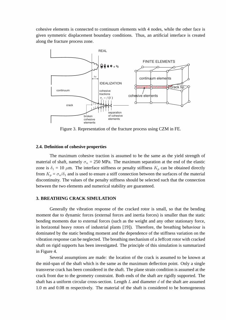
cohesive elements is connected to continuum elements with 4nodes, while the other face isgiven symmetric displacement boundary conditions. Thus, an artificial interface is createdalong the fracture process zone.
Figure 3. Representation of the fracture process using CZM in FE.
2.4. Definition of cohesive properties
The maximum cohesive traction is assumed to be the same as theyield strength ofmaterial of shaft, namelyσn = 250 MPa. The maximum separation at the end of the elasticzone isδ1 = 10 µm. The interface stiffness or penalty stiffnessKp can be obtained directlyfrom Kp = σn/δ1 and is used to ensure a stiff connection between the surfacesof the materialdiscontinuity. The values of the penalty stiffness should be selected such that the connectionbetween the two elements and numerical stability are guaranteed.
3. BREATHING CRACK SIMULATION
Generally the vibration response of the cracked rotor is small, so that the bendingmoment due to dynamic forces (external forces and inertia forces) is smaller than the staticbending moments due to external forces (such as the weight and any other stationary force,in horizontal heavy rotors of industrial plants [19]). Therefore, the breathing behaviour isdominated by the static bending moment and the dependence ofthe stiffness variation on thevibration response can be neglected. The breathing mechanism of a Jeffcott rotor with crackedshaft on rigid supports has been investigated. The principle of this simulation is summarizedin Figure 4.
Several assumptions are made: the location of the crack is assumed to be known atthe mid-span of the shaft which is the same as the maximum deflection point. Only a singletransverse crack has been considered in the shaft. The planestrain condition is assumed at thecrack front due to the geometry constraint. Both ends of the shaft are rigidly supported. Theshaft has a uniform circular cross-section. LengthL and diameterd of the shaft are assumed1.0 m and 0.08 m respectively. The material of the shaft is considered to be homogeneous

Figure 4. Principle of the breathing crack simulation usingFE and MBS.
and isotropic. Young’s modulusE, Poisson’s ratioν and mass densityρ are 210 GPa, 0.3 and7850 kg/m3, respectively. Yield strengthσY and ultimate strength of materialσmax are 250MPa and 400 MPa, respectively.
4. DYNAMIC BEHAVIOUR OF ROTATING FLEXIBLE CRACKED SHAFT
The FE model of the elastic cracked shaft is transferred intoa MBS in order to computethe displacements due to the dynamic loads acting during rotation at different rotating speeds.Although the duration of each step of the breathing mechanism is relatively long and timeconsuming and the breathing mechanism results are based on transverse vibration response ofa rotating shaft from MBS software, by reducing the number of degrees of freedom of the FEmodel, it has been shown that breathing mechanism in rotating shafts can be reproduced byFE and MBS. The aim of the study is to analyse the additional deflection due to the breathingcrack during one revolution of the shaft. Using MBS, the inertia forces can be observed andtaken into account and the transverse vibration response results are used as deflection inputfor the FE model in order to predict the breathing mechanism during rotation of shaft.
The breathing mechanism generated by the rotating bending load used in the literaturehas some limitations. Due to the presence of inertia forces,the dynamic behaviour of rotatingstructures is different from those of static structures. Although in case of weight dominance,the amplitude of the vibration response due to inertia forces is smaller than due to weightforces, elastic forces and presence of a crack (if the shaft is assumed to be balanced), usingthe inertia force into account will yield more accurate results. The 3D finite element calcula-tions allow the breathing mechanism to be predicted accurately. The breathing mechanism isstrongly influenced by the weight of the shaft. In many publications on the breathing crack,

assumptions on the breathing mechanism have been made. For transverse cracks in rotatingshafts, the variation of the crack front line perpendicularto the crack front has been exten-sively addressed by Darpe et al. [20]. This breathing crack form is also used by Jun et al.[21], and Sinou and Lees [22]. An elliptical shape has been proposed by Bachschmid et al.[19], and Shih [23]. Based on finite element model simulation and some reported experi-mental results and in order to model more realistically the breathing crack mechanism duringrotation, the breathing crack shape is modelled by a parabolic shape, that opens and closesdue to bending stresses (Liong and Proppe [24]).
The idea is that the vibration responses in the centroid of the shaft obtained fromMBS software are exported into FE model in order to analyse thebreathing mechanism, asschematically shown in Figure 5. The opening crack is simulated for one cycle of revolutionof the cracked shaft specimen in steady state condition. Thebreathing mechanism is generatedby the bending due to external load (weight) by increasing the angle by steps ofπ/12 rad. Thebreathing (open and closed crack areas are evaluated in eachangular step) is observed by thenodal displacement and the stress distribution (tensile orcompressive stress) around the crack.The prediction of the breathing mechanism was performed by the following steps: for eachangle of rotation, stress distribution due to the bending moment is recorded over the crosssection. Compressive (negative) stresses indicate the closed region. The crack opens wherezero or very small positive numerical values of stresses appear and the contact forces vanish.Displacements and stresses can be observed at the crack surfaces.
Figure 5. Transfer of the vibration responses from MBS into FE.
Results of the relative crack depth versus the shaft rotationangle during breathing areshown in Figure 6. Four functions are used to approximate therelative crack depth, namelylinear, quadratic, harmonic and power function. Table 1 gives the approximations for a relativecrack deptha/d = 0.1 as function of shaft rotation angleθ. It is shown that harmonic andquadratic function have minimal error and the nearest correlation with the simulation results.In this sense, the relative crack depth during crack openingshould be understood not as linearincreasing but as harmonic function or quadratic polynomial.

Figure 6. Curve fitting of breathing of the simulation results.
Table 1. Curve Fitting of the simulation results fora/d = 0.1, θ in [rad]
Model Mathematical model Sum of square error R-square
Linear function a/d = 0.039θ + 0.001 0.000 580 0.951 6Quadratic polynomial a/d =-0.012θ2 + 0.076θ - 0.020 0.000 011 0.999 0Harmonic function a/d = 0.010 sin(0.593θ -0.145) 0.000 006 0.999 5Power function a/d = 0.123θ0.373 - 0.077 0.000 099 0.991 7
Due to the presence of gravity, the upper portion of the cracked rotor at the beginningof a rotation is under compression and the crack is closed. Asthe rotor continues to rotateand the gravity direction being constant, the upper part nowcomes in the lower tensile regioncausing the crack to open. The accuracy of the results is demonstrated through comparisonwith results available in the literature. As long as the relative crack depth is small (a/d ≤ 0.2),the model of breathing crack parallel to crack front line or straight line may be used [24]. Incomparison with the crack closure straight line model, the simulation results are only differentfor rotation angles less thanπ/2. Figure 7 displays the comparison between simulation resultsand crack closure straight line model for a shallow cracka/d=0.1, from the beginning untilthe crack opens completely. With respect to the crack closure straight line model, it can beobserved that the relative crack deptha/d during the rotation is different from the simulation.Crack opening of the crack closure straight line model increases with the same amount forevery step of angle of rotation, i.e.a (θ) = a θ/π wherea is crack depth andθ is angle ofrotation until half revolution (π radian). It can be observed that crack opening of the straightline model increases faster than crack opening of the simulation until an angle ofπ/3.
Another model to describe the breathing crack is a bilinear model as shown in Figure8. The crack begins openning at shaft rotation angleθ0 and at crack front angleα that definesthe angle between two crack front lines. The shaft rotates with shaft rotation angleθ and the

0o
30o
60o
90o
45o
75o
105o
120o
150o
180o
135o
165o
Figure 7. Comparison between simulation results and crack closure straight line model for ashallow cracka/d=0.1.
crack front angleα increases until maximum crack widthbmax is reached. The crack frontangleα and the crack widthb non-linearly increase during rotation fromθ0 to θmax (Figure 9and 10). One can obtain the crack front angleα and the crack width as function of the shaftrotation angle respectively by
maxb
b
a
0a
a
Figure 8. Crack closure bilinear model.
α =
0 θ ≤ θ0 = π
6crack still closed;
−0.018θ3 + 0.016θ2 + 0.35θ + 2.4 θ0 ≤ θ ≤ θmax crack opens;π θ ≥ θmax = 5π
6crack opens completely
(6)

0θ [rad]
α [r
ad]
α = − 0.084*θ2 + 0.51*θ + 2.4α = − 0.018*θ3 + 0.016*θ2 + 0.35*θ + 2.4
Simulation Quadratic Cubic
ππ/22π/3
5π/6
π
Figure 9. Crack front angleα during rotation of shaft.
00
0.1
0.2
0.3
0.4
0.5
0.6
0.7
0.8
0.9
1
θ [rad]
b/b m
ax
b/b
max = − 0.069*θ3 + 0.2*θ2 + 0.36*θ − 0.066
b/bmax
= 0.076*θ4 − 0.54*θ3 + 1.1*θ2 − 0.23*θ − 0.0056
Simulation Cubic 4th degree
ππ/2
Figure 10. Normalized crack widthb/bmax during rotation of shaft.
b/bmax =
0 θ ≤ θ0 = π
6crack still closed;
0.076θ4 − 0.54θ3 + 1.1θ2 − 0.23θ − 0.0056 θ0 ≤ θ ≤ θmax crack opens;1 θ ≥ θmax = 5π
6crack opens completely
(7)
For the relative crack deptha/d = 0.1, the crack begins to open atθ0 = π/6 andα = 5π/6 whilethe crack opens completely atθmax = 5π/6 andα = π. Therefore, the crack front angle and thecrack width during crack opening are
α = −0.018θ3 + 0.016θ2 + 0.35θ + 2.4π
6≤ θ ≤
5π
6(8)
b/bmax = 0.076θ4 − 0.54θ3 + 1.1θ2 − 0.23θ − 0.0056π
6≤ θ ≤
5π
6(9)
In order to get more accurate interpretation, the relative crack area (i.e ratio of thepartially open crack area to the fully open crack area) with respect to the angle of rotation is

used as shown in Figure 11. Results are similar when the crack closes. The relative crack areaof simulation results is in good agreement with the crack closure straight line model betweenrotation anglesπ/3 and5π/6 and with the bilinear model in the range from 0 andπ, but thereare some relevant differences with respect to the crack closure perpendicular line model usedby Darpe et al. [20]. Another interpretation, the area moment of inertia about the rotation axiscan be approximated. Finally, the stiffness of the cracked shaft can be evaluated (stiffnessis found to vary linearly with the area moment of inertia). The normalised stiffness (ratiobetween stiffness of the cracked shaft and stiffness of the uncracked shaft) is presented asshown in Figure 12. It is shown that the normalised stiffnessbetween simulation results andthe crack closure bilinear model is very close, which validates the bilinear model.
, quadratic fit
Figure 11. Comparison of the relative crack area between simulation results, crack closurestraight line, perpendicular line and bilinear model for a shallow cracka/d=0.1.
kk
Figure 12. Comparison of the normalised stiffness between simulation results, crack closurestraight line, perpendicular line and bilinear model for a shallow cracka/d=0.1.

5. CONCLUSIONS
In this study, a simulation process of FE and MBS is employed. Acracked elasticshaft is modelled by FE which is transferred into an MBS model in order to study the stiffnessvariation due to breathing at different rotating speeds. The vibration responses in the centroidof the shaft obtained from MBS have been transferred again into an FE model in order toobserve the breathing mechanism. The results have shown that the breathing mechanism isinfluenced by the vibration due to inertia forces, by rotating speed and by relative crack depth.It is shown that the relative crack depth during crack opening should be understood not aslinear increasing but as harmonic function or quadratic polynomial. It can be noted that aslong as the relative crack depth is small, the model of breathing crack parallel to crack frontline (crack closure straight line model) or the bilinear model may be used. The main differencewith respect to the crack closure straight line is that the crack opening in the simulation is notconstant at the beginning. In order to get more accurate interpretation, the relative crack area(i.e ratio of the partially open crack area to the fully open crack area) with respect to theangle of rotation is used. The simulated relative crack areais in good agreement with thecrack closure straight line model between rotation anglesπ/3 and5π/6 and with the bilinearmodel in the range from 0 andπ. Furthermore, the area moment of inertia about the rotationaxis can be approximated. From this information, the stiffness variation of the shaft can beevaluated and a breathing steering function can be calibrated. This function may be used eitherin analytical or one dimensional finite element formulations in order to evaluate changes inthe natural frequencies or to carry out stability analysis of the cracked rotor. The normalisedstiffness (ratio between stiffness of the cracked shaft andstiffness of the uncracked shaft) hasshown that the normalised stiffness between simulation results and the crack closure bilinearmodel is very close, which validates the bilinear model accurately.
In light of the presented results and the conclusions, several subjects can be recom-mended for future research. First of all, the CZM could be extended to consider plasticityand crack propagation of the cracked shaft. Another important point on which the knowledgecould be improved is the prediction of crack propagation on cracked rotor and residual lifeestimation from static loads and from the dynamical behaviour of cracked rotors. The CZMcan be easily implemented in FEM to analyze the dynamic behaviour of a cracked shaft, isrecommended to use CZM to study different types of cracks suchas longitudinal and slantcracks. Some other parameters such as internal damping, unbalance and thermal transientscould be studied to obtain results for their effect on the breathing mechanism as well as onstability of vibration. Further analysis on crack morphology is extremely important to under-stand the dynamic behaviour of cracked shaft. This would include shallow and wide cracks.Effects of rotating speed on breathing mechanism could alsobe of interest.

6. REFERENCES
[1] Georgantzinos S.K., Anifantis N.K., “An insight into the breathing mechanism of a crack in a rotatingshaft”. J. Sound and Vibration318, 279-295, 2008.
[2] Sabnavis G., Kirk R.G., Kasarda M., “Cracked shaft detection and diagnostics: a literature review”.Shock-Vibration Digest36(4), 287-296, 2004.
[3] Kumar V., Rastogi C., “A brief review on dynamics of a cracked rotor”. Int. J. Rotating Machinery, 1-6,2009.
[4] Bachschmid N., Pennachi P., Tanzi E., “Some remarks on breathing mechanism, on non-linear effects andon slant and helicoidal cracks”.Mechanical Systems and Signal Processing22, 879-904, 2008.
[5] Bachschmid N., Pennachi P., Tanzi E., “ Cracked rotors”.Springer-Verlag Berlin, 109-144, 2011.
[6] Andrieux S., Vare C., “A 3D cracked beam model with unilateral contact. Application to rotors”.EuropeanJ. Mechanics A/Solids21, 793-810, 2005.
[7] Vare C., Andrieux S., “Modeling of a cracked beam section under bending”. Proc. the 18th Int. Conf. onStructural Mechanics in Reactor Technolohy (SMiRT 18, Beijing, China, 2005.
[8] Arem S.A., Maitournam H., “A cracked beam finite element for rotating shaft dynamics and stability anal-ysis”. J. Mechanics and Structures3(5), 893-910, 2008.
[9] Bouboulas A.S., Anifantis N.K., “Finite element modeling of a vibrating beam with a breathing crack:observations on crack detection”.Structural Health Monitoring, 1-15, 2010.
[10] Dugdale D.S., “Yielding of steel sheets containing slits”. J. Mechanics and Physics Solid7, 100-104, 1960.
[11] Barenblatt G.I., “The mathematical theory of equilibrium crack in brittle fracture”.Adv. Applied Mechanics7, 55-129, 1962.
[12] Siegmund T., Brocks W., “Tensile decohesion by local failure criteria”. Technische Mechanik, Band 18 Heft4, 261-270, 1998.
[13] Siegmund T., Brocks W., “A numerical study on the correlation between the work of separation and thedissipation rate in ductile fracture”.Eng. Fracture Mechanics67, 139-154, 2000.
[14] Anvari M., Scheider I., Thaulow C., “Simulation of dynamic ductile crack growth using strain-rate andtriaxiality-dependent cohesive elements”.Eng. Fracture Mechanics73, 2210-2228, 2006.
[15] Scheider I., “Derivation of separation laws for cohesive models in the course of ductile fracture”.Eng.Fracture Mechanics76, 1450-1459, 2009.
[16] Banerjee A., Manivasagam R., “Triaxiality dependent cohesive zone model”.Eng. Fracture Mechanics76,1761-1770, 2009.
[17] Shet C.. Chandra N., “Analysis of energy balance when using cohesive zone models to simulate fractureprocesses”.ASME124, 440-450, 2002.
[18] Li H., Chandra N., “ Analysis of crack growth and crack-tip plasticity in ductile materials using cohesivezone models”.Int. J. Plasticity19, 849-882, 2003.
[19] Bachschmid N., Pennachi P., Tanzi E., “On the evolutionof vibrations in cracked rotors. ”.Proc. the 8thIFToMM Int. Conf. on Rotor Dynamics, Seoul, Korea, 2010.
[20] Darpe A.K., Gupta K., Chawla A., “Coupled bending, longitudinal and torsional vibrations of a crackedrotor”. J. Sound and Vibration269(1-2), 33-60, 2004.
[21] Jun O.S, Eun H.J., Earmme Y.Y:, Lee C.W., “Modelling andvibration analysis of a simple rotor with abreathing crack”.J. Sound and Vibration155(2), 273-290, 1992.
[22] Sinou J.J., Lees A.W., “The influence of cracks in rotating shaft”.J. Sound and Vibration285(4-5), 1015-1037, 2005.
[23] Shih Y.S., Chen J.J., “Analysis of fatigue crack growthon a cracked shaft”.Int. J. Fatigue19(6), 477-485,1997.
[24] Liong R.T., Proppe C., “Application of the cohesive zone model to the analysis of a rotor with a transversecrack”. Proc. the 8th Int. Conf. on Structural Dynamics, Leuven, Belgium, 2011.