Unit8 morning Brush my teeth, brush my teeth. Brush, brush, brush.
NASA Technical Memorandum 107158
A Brush Seals Program Modeling and Developments
Robert C. Hendricks Lewis Research Center Cleveland, Ohio
Ralph Flower Cross Mfg. Ltd. Devizes, United Kingdom
Harold Howe Technetics Corp. DeLand, Florida
Prepared for the 9th International Symposium on Transport Phenomena in Thermal-Fluids Engineering sponsored by the Pacific Centre of Thermal Fluids Engineering Singapore, Republic of Singapore, June 25-28,1996
National Aeronautics and Space Administration
https://ntrs.nasa.gov/search.jsp?R=19960022947 2018-06-20T04:17:29+00:00Z
ERRATA
NASA Technical Memorandum 107158
A BRUSH SEALS PROGRAM MODELING AND DEWLOPMENTS
Robert C. Hendricks NASA Lewis Research Center
Cleveland, Ohio
Ralph Flower
Devizes, United Kingdom cross Mfg. Ltd.
and
Harold Howe Technetics Corp. DeLand, Florida
Page 6: Add reference to the legend in Figure 7 so that it reads:
Figure 7.-Dimensionless flow loss versus Reynolds number taken from Ergun (1 1) with superimposed brush seal data for air, carbon dioxide, and helium from Carlile et al. (5). Grid background from Bird, R.B.; Stewart, W.E.; and Lightfoot, E.N: Transport phenomena, John Wiley Press, New York, 1960, p. 200.
A Brush Seals Program Modeling and Developments
Robert C. Hendricks, Ralph Flower", Harold Howe** National Aeronautics and Space Administration
Lewis Research Center Cleveland, Ohio 44135
"Cross Mfg. Ltd. ""Technetics Cop . Devizes U.K. DeLand Florida
ABSTRACT
Some events of a U.S. ArmyNASA Lewis Research Center brush seals program are reviewed, and the development of ceramic brush seals is described. Some preliminary room-temperature flow data are modeled and compare favorably to the results of Ergun. Keywords: Brush seals; Ceramics; Porous media; and Flow modelling.
INTRODUCTION
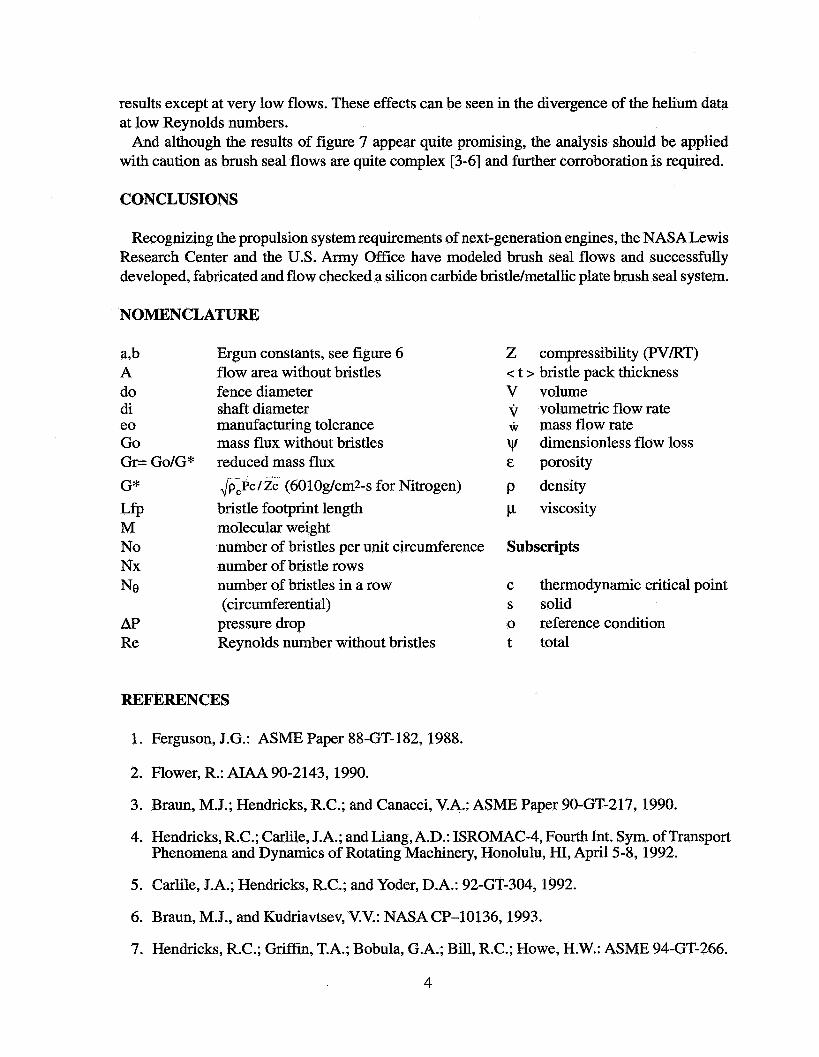
Recognizing the remarkable brush seal accomplishments of John Ferguson of Rolls Royce [ 11 and Ralph mower of Cross Mfg. Ltd. [2], figure 1, NASA Lewis Research Center embarked on a program to develop the fundamentals characterizing flow and dynamics of brush seals.
The program entailed
(1) Developing a heuristic brush seal bulk flow model and code for determining the flow and pressure drop in brush seal systems that would be suitable for both designers and researchers.
(2) Utilizing an existing water tunnel facility and fabricating an experimental oil tunnel facility to visualize flows through simulated brush seal sections.
(3) Setting up an approach for determining rub characteristics, debris, bristle flexure cycles, and seal life associated with long-term operations for the brush seal and rub runner as a system (tribopairing).
(4) Integrating observations from an airflow tunnel of the flow through sequences of nylon bristle brushes, such as bristle flexure, flutter, edge loss, and clearances leakage.
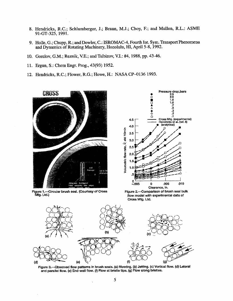
Toward this end, a bulk flow model and computer code were developed. The model centered on the forces acting on a single bristle and the flow through a porous medium consisting of fibrous type materials. Although the details of the brush are proprietary, estimates of its dimensions and allowances for multiple bristles and packing were made and input into the model. By using one data point from Cross Mfg. Ltd., the geometric and flow parameters were established, and predictions of flow and pressure drop followed as illustrated in figure 2.
A simulated brush seal section with Lucite bristles was fabricated and placed into a water tunnel at NASA Lewis. The flow was seeded with magnesium oxide particles and illuminated with a sheet of laser light. The light provided two-dimensional slices of the flow, revealing a complexity not envisioned (figure 3). By moving the light beam, the tunnel was surveyed to
1
show flows along the bristles and up and down through the bristles, revealing complex vortex attachments and surface boundary layers. Video tapes of these flow fields were made to illustrate the complexity of brush seal flows [3].
Using these flow visualization methods a special oil tunnel was fabricated as well as sets of simulated brush seal sections with Lucite bristles. Because the refraction indexes of the Lucite and the oil were matched, these sections could not be seen once they were immersed in the oil, but the magnesium oxide flow tracers illuminated by a sheet of laser light provided two-dimensional slices of flows through the sections that were recorded on video tape. Frame-grabbing techniques and software developed were used to quantify these flows.
The simple brush seal bulk flow model and code evolved into more complex forms, including extensions to other gases by using the theory of corresponding states. The code still required geometric information and one data point to determine the flow and pressure drop [4,5]. Concurrently, a numerical method was developed to characterize the two-dimensional flow patterns about sets of pins simulating flow patterns in brush seals. The code has been validated experimentally and faithfully reproduced the flow patterns associated with a variety of two-dimensional arrays of pins [6].
DEVELOPMENT OF CERAMIC BRUSH SEALS
Testing and modeling brush seal systems [7,8] including flow, thermal effects, and rubbing effects and projecting the sealing needs of future propulsion systems revealed the need for seals that can withstand high surface speeds and temperatures. Therefore, a brush seal made of silicon carbide bristles and metallic plates and an aluminum oxide brush seal were to be developed. The former is anticipated to operate at 1200 fps and 1500 O F and is suitable for configurations now in the design stage. The latter is anticipated to operate at 2000 "F and can be used in the next generation of engines. Both types could be used in static sealing applications.
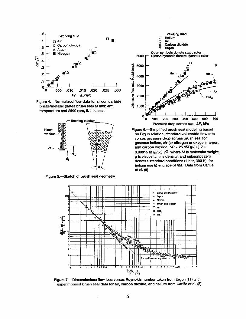
The craftsmanship of the 5.1-in.-diameter silicon carbide bristle/metallic plate brush seal fabricated and delivered by Cross Mfg. Ltd. was superb. Each bristle appeared to be well manufactured and to be placed as well as any metallic bristle with tips ground to a perfect contour to provide the standard 5-mil interference. Truly a remarkable achievement. The silicon carbide bristle/metallic plate brush seal was installed for flow testing. At first the rotor could be turned in only one direction. After operation it could be rotated by hand in either direction but rotates freely in one direction only. The flow rate data at ambient temperatures were consistent (figure 4) considering that a brush seal is not a positive seal system and leaks like a porous medium.
OTHER MODELING EFFORTS
In addition to the modeling already cited, several other researchers have developed models to correlate and interpret brush seal flow data. These models also require heuristic information and many follow the geometric considerations and modeling of the NASAmodels. In some cases the design methods are characterized, but the details for application are absent. In other cases the results are simply related to a flow coefficient, and others they are related to geometric packing [9] and provide a simple code methodology. Other flexure models follow the NASA bristle loading model. Still others have provided some results for geometric variations [lo] or for other
2
types of ceramic configurations, such as fiberglass. Although these models and the NASAmodels provide physical insight into brush seal flow characteristics, the Ergun [ 111 porous flow model (with modifications for brush seals, see figure 5)
could be used to correlate and predict brush seal flows with simplicity (figure 6) where the constants a and b are empirically determined [ 121. Two data points would be required to establish geometric and flow parameters, and the gaseous results for simple corresponding-states fluids appear to fit quite well. The effects of surface speed are not well established.
However a direct application of the Ergun model provides useful dimensionless forms:
=150/(Re/(l-~))+1.75
Re = 1.5God/p GO = poV = w/ A A = n(dg - d2)/4 D, = 1.5d (3)
&=Vopen/Vtotal=l-Vs/Vt =1-nNod2/((2)(1+do/di)< t >cos(e+'p)) (4)
For a well constructed brush seal, the footprint length becomes
Lfp = (d + eo)/cos(0 + 'p) (5)
where eo is the manufacturing tolerance, and the total number of bristles per row becomes
and the upper bound on the thickness and number of rows becomes
< t >= dNx = nddiNo/Ne (7)
where No is the number of bristles per unit length as provided by the manufacturer or by micro- examination of the brush interface.
The values of v and Re/( 1 - E) are calculated from the data set of Carlile et al. [5] and overplotted on the results presented by Ergun [ 1 11 as illustrated in figure 7. The principles of corresponding states were applied to the thermophysical properties used in reduction of the data.
While some differences are noted between the working fluids ( helium, air, carbon-dioxide) the major scatter appears at low pressure drops and flow rates where experimental error is most acute. The dynamic leakage at low surface speeds does not differ significantly from the static
3
results except at very low flows. These effects can be seen in the divergence of the helium data at low Reynolds numbers.
And although the results of figure 7 appear quite promising, the analysis should be applied with caution as brush seal flows are quite complex [3-61 and further corroboration is required.
CONCLUSIONS
Recognizing the propulsion system requirements of next-generation engines, the NASA Lewis Research Center and the U.S. Army Offlice have modeled brush seal flows and successfully developed, fabricated and flow checked a silicon carbide bristle/metallic plate brush seal system.
NOMENCLATURE
a,b A do di eo Go Gr= Go/G* G"
M No Nx Ne
LfP
AP Re
Ergun constants, see figure 6 flow area without bristles fence diameter shaft diameter manufacturing tolerance mass flux without bristles reduced mass flux Jp,pc/zc (6010g/cm2-s for Nitrogen) bristle footprint length molecular weight number of bristles per unit circumference number of bristle rows number of bristles in a row (circumferential)
pressure drop Reynolds number without bristles
Z compressibility (PVLRT) < t > bristle pack thickness V volume v volumetric flow rate i mass flow rate w dimensionless flow loss E porosity p density p viscosity
Subscripts
c thermodynamic critical point s solid o reference condition t total
REFERENCES
1. Ferguson, J.G.: ASME Paper 88-GT-182, 1988.
2. Flower, R.: AIAA 90-2143, 1990.
3. Braun, M.J.; Hendricks, R.C.; and Canacci, V.A.: ASME Paper 90-GT-217, 1990.
4. Hendricks, R.C.; Carlile, J.A.; and Liang, A.D.: ISROMAC-4, Fourth Int. Sym. of Transport
5. Carlile, J.A.; Hendricks, R.C.; and Yoder, D.A.: 92-GT-304, 1992.
Phenomena and Dynamics of Rotating Machinery, Honolulu, HI, April 58,1992.
6. Braun, M.J., and Kudriavtsev, V.V.: NASA CP-10136,1993.
7. Hendricks, R.C.; Griffin, T.A.; Bobula, G.A.; Bill, R.C.; Howe, H.W.: ASME 94-GT-266.
4
8. Hendricks, R.C.; Schlumberger, J.; Braun, M.J.; Choy, F.; and Mullen, R.L.: ASME 91-GT-325, 1991.
9. Holle, G.; Chupp, R.; and Dowler, C.: ISROMAC-4, Fourth Int. Sym. Transport Phenomena and Dynamics of Rotating Machinery, Honolulu, HI, April 5-8,1992.
10. Gorelov, G.M.; Reznik, V.E.; and Tsibizov, V.I.: #4, 1988, pp. 43-46.
11. Ergun, S.: Chem Engr. Prog., 43(93) 1952.
12. Hendricks, R.C.; Flower, R.G.; Howe, H.: NASA CP-0136 1993.
Pressure drop,bars e 2.5 0 2.0
1.5 0 1 .o A .7 n .5 + .3 0 .2 Q .I - Cross Mfg. (experimental) - Hendricks et al. (ref. 8) 4.5
4.0 S .- E
3 3.0 .5 $' 2.5 2
g 3.5
g 2.0
- 5 1.0
= 0
a 5 1.5
.5
0 -.005 0 ,005 .010
Clearance, in.
3
Figure 1 .-Circular brush seal. (Courtesy of Cross Figure 2.-Comparison of brush seal bulk flow model with experimental data of Cross Mfg. Ltd.
Mfg. Ltd.)
Figure 3.4bsenred flow patterns in brush seals. (a) Rivering. (b) Jetting. (c) Vortical flow. (d) Lateral and parallel flow. (e) End-wall flow. (f) Flow at bristle tips. (g) Flow along bristles.
5
Working fluid *8 m7 c Air
*6
~ :; & .3
- 2 -
0 . o Carbon dioxide
OmY - A Argon - Nitrogen A - m - m e i@
Working fluid 17 Helium 0 Air A Carbon dioxide V Argon
Open symbols denote static rotor Closed symbols denote dynamic rotor
5000 V 6ooo F m
He-\ Q Air, 4000 '\?/ \
3000
2000
1000
n V
0 100 200 300 400 500 600 700 Pressure drop across seal, AP, kPa
Figure 6.4implified brush seal modeling based on Ergun relation, standard volumetric flow rate verses pressure drop across brush seal for gaseous helium, air (or nitrogen or oxygen), argon, and carbon dioxide. AP = 25 m(p/pO) W + 0.0001 5 M (plpo) V2, where M is molecular weight, p is viscosity, p is density, and subscript zero denotes standard conditions (1 bar, 300 K); for helium use M in place of f,/M Data from Carlile et al. (5)
Figure 5.4ketch of brush seal geometry.
D,oO* 1 c 1-€
Figure 7.-Dimensionless flow loss verses Reynolds number taken from Ergun (1 1) with superimposed brush seal data for air, carbon dioxide, and helium from Carlile et al. (5).
6
REPORT DOCUMENTATION PAGE
I I
I. TITLE AND SUBTITLE
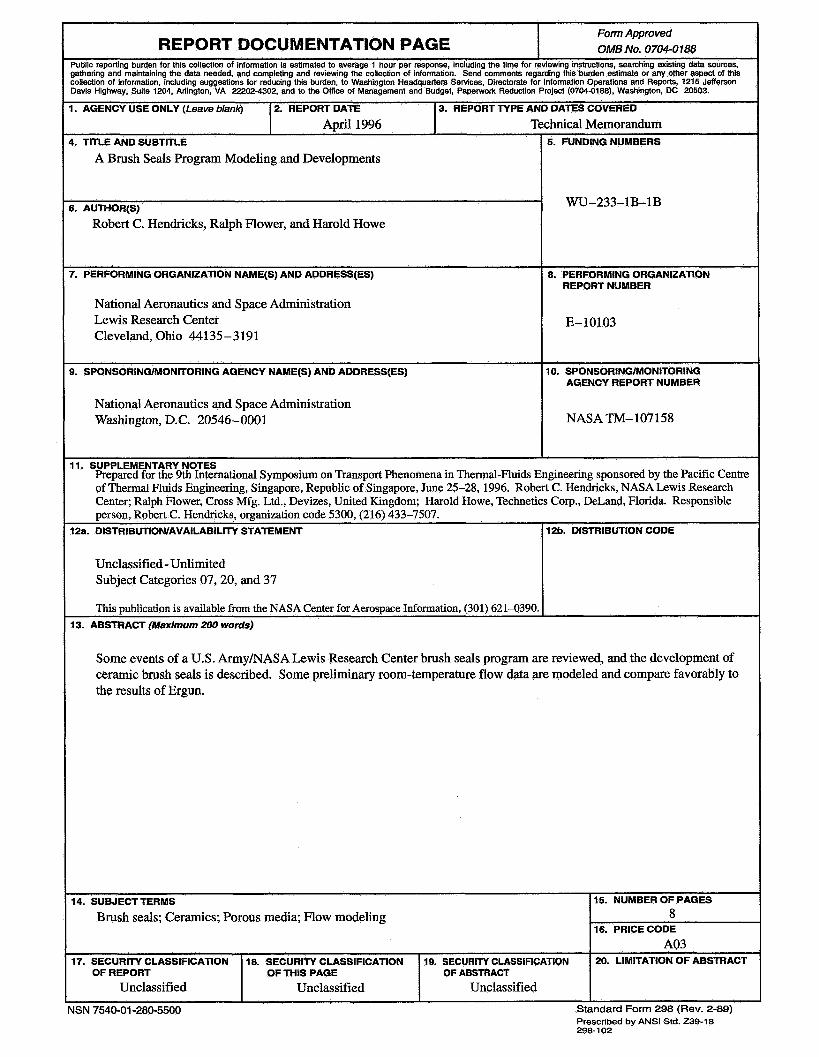
A Brush Seals Program Modeling and Developments
Form Approved OMB NO. 0704-0188
i. AUTHOR@)
Robert C. Hendricks, Ralph Flower, and Harold Howe
I. AGENCY USE ONLY (Leave blankj 2. REPORT DATE
A~rill996
r. PERFORMING ORGANIZATION NAME(S) AND ADDRESS(ES)
3. REPORT TYPE AND DATES COVERED
Technical Memorandum
National Aeronautics and Space Administration Lewis Research Center Cleveland, Ohio 44135-3191
14. SUBJECT TERMS
Brush seals; Ceramics; Porous media; Flow modeling
17. SECURITY CLASSIFICATION 18. SECURITY CLASSIFICATION 19. SECURITY CLASSIFICATION OF REPORT OF THIS PAGE OF ABSTRACT
Unclassified Unclassified Unclassified
3. SPONSORlNG/MONlTORlNG AGENCY NAME(S) AND ADDRESS(ES)
15. NUMBER OF PAGES 8
A03 16. PRICE CODE
20. LIMITATION OF ABSTRACT
National Aeronautics and Space Administration Washington, D.C. 20546-0001
5. FUNDING NUMBERS
WU-233-1B-1B
8. PERFORMING ORGANIZATION REPORT NUMBER
E-10103
10. SPONSORINGIMONITORING AGENCY REPORT NUMBER
NASATM-107158
11. SUPPLEMENTARY NOTES Prepared for the 9th International Symposium on Transport Phenomena in Thermal-Fluids Engineering sponsored by the Pacific Centre of Thermal Fluids Engineering, Singapore, Republic of Singapore, June 25-28,1996. Robert C. Hendricks, NASA Lewis Research Center; Ralph Flower, Cross Mfg. Ltd., Devizes, United Kingdom; Harold Howe, Technetics Corp., DeLand, Florida. Responsible person, Robert C. Hendricks, organization code 5300, (216) 433-7507.
12a. DlSTRlBUTlONlAVAILABlLlTY STATEMENT
Unclassified -Unlimited Subject Categories 07,20, and 37
This publication is available from the NASA Center for Aerospace Information, (301) 621-0390. 13. ABSTRACT (Maximum 200 words)
12b. DISTRIBUTION CODE
Some events of a U.S. ArmyNASA Lewis Research Center brush seals program are reviewed, and the development of ceramic brush seals is described. Some preliminary room-temperature flow data are modeled and compare favorably to the results of Ergun.