A B i G id I lli DCC D dA Beginners Guide to Installing...
57
AB i G id I lli DCC D d AB i G id I lli DCC D d A Beginners Guide to Installing DCC Decoders A Beginners Guide to Installing DCC Decoders By Mark Schutzer PCR Regional Convention, Dublin, CA April 2013 Copies of this presentation can be found at http://www.markschutzer.com
Transcript of A B i G id I lli DCC D dA Beginners Guide to Installing...

A B i G id I lli DCC D dA B i G id I lli DCC D dA Beginners Guide to Installing DCC DecodersA Beginners Guide to Installing DCC Decoders
By Mark SchutzerPCR Regional Convention, Dublin, CA
April 2013Copies of this presentation can be found at
http://www.markschutzer.com

Clinic OverviewClinic Overview
Installing DCC decoders• This clinic will show beginners how to install DCC decoders
in both Steam and Diesel locomotives.• After presenting some general decoder information I will
guide you thorough a step by step installation example in both Steam and Diesel locomotives.
• Some advanced sound decoders will also be discussed
April 2013 DCC Decoders Mark Schutzer 2

DCC Decoders OverviewDCC Decoders Overview
Electrical pickup review for steam locomotivesT i l I t tiTypical InstructionsMotors Decoder selection – size type and current ratingDecoder selection – size, type, and current ratingLighting – Incandescent bulbs and LED’sConnectors and wiring techniquesg qSteam and Diesel installation examplesAdvanced installations - SoundMore examples…Sources
April 2013 DCC Decoders Mark Schutzer 3

Electrical Pickup Electrical Pickup –– Steam LocomotivesSteam Locomotives
April 2013 DCC Decoders Mark Schutzer 4

Typical InstructionsTypical Instructions
Generic Instructions• Mount decoder• Isolate motor contacts from track and frame• Wire motor connections
– Red wire to right rail, Orange wire to motor positive– Black wire to left rail, Grey wire to motor negative
• Replace 1.5 volt bulbs or add limiting resistors• Wire lighting circuits
– Blue wire is positive common for all function outputs– White wire is headlight output (F0 forward)– Yellow wire is rear light output (F0 reverse)– Green wire is F1 output (if supported)– Violet wire is F2 output (if supported)
• Test on the programming track• Program as desired…
April 2013 DCC Decoders Mark Schutzer 5

Decoder WiringDecoder Wiring
Right Rail(Engineer's Side)
Motor+ -
D d
Right Track Power Pickup
Orange
Black
Gray
Left Track Power Pickup
Motor +
Red
(Engineer's Side)Motor -
Decoder
Violet
Green Output 3 (F1)
Yellow
Output 4 (F2)
Blue
Output 1 (F0)
Headlight
WhiteLeft Rail
Light Common
Output 2 (F0)(Fireman's Side)
Rearlight
Extra light #1
Extra light #2
April 2013 DCC Decoders Mark Schutzer 6

Motors Motors –– Early Brass LocosEarly Brass Locos

Original MotorsOriginal Motors
Original Motors• Most early motors are open frame types• Poor slow speed operationPoor slow speed operation• High starting voltage and current• Not very efficient
Hi h li d ll• High slip and stall currents• Require a higher rated decoder, costing more money $$$• Sometimes require work to isolate from frame
• Replacement strongly recommended!
April 2013 DCC Decoders Mark Schutzer 8

Original MotorsOriginal Motors
Some typical open frame motor numbersMotor TypeOpen Frame
Free RunningCurrent (Amps)
Typical loadedCurrent (Amps)
Stall Current(Amps)Open Frame
KTMCurrent (Amps)
12 voltsCurrent (Amps)
12 volts(Amps)12 volts
Small 0.6 1.0 or more 2.0
M di 0 6 1 2 2 9 3 0Medium 0.6 1.2 or more 2.9 – 3.0
Large 0.7 1.5 or more > 3.5
April 2013 DCC Decoders Mark Schutzer 9

Can MotorsCan Motors
Can motor advantages• More efficient, much lower current draw• Most are skew wound for very good slow speed
performance• Slower starting speeds and excellent slow speed
torqueB l d f ll l• Better slow speed performance allows lower gearbox ratios to be used reducing the top end noise.
• DCC friendly; isolated terminals and most HODCC friendly; isolated terminals, and most HO sized motors have stall currents under or about 1 amp.
April 2013 DCC Decoders Mark Schutzer 10

Can MotorsCan Motors
Some typical can motor numbers
Motor TypeNWSL
Free RunningCurrent (Amps)
Max. ContinuousCurrent (Amps)
Stall Current(Amps)
Stall Torque (Oz -in )NWSL Current (Amps)
12 voltsCurrent (Amps)
12 volts(Amps)12 volts
(Oz. in.)
12270-9 0.08 0.25 0.54 0.61
16307-9 0.05 0.34 0.95 0.79
18367 9 0 19 0 40 1 20 2 5018367-9 0.19 0.40 1.20 2.50
20324-9 0.05 0.36 0.90 1.40
N scale decoders okay for all of these! • 1 amp continuous rated
April 2013 DCC Decoders Mark Schutzer 11
• 1 amp continuous rated

Selecting a decoderSelecting a decoder
Choices, choices, choices…• Decoder rating should be in excess of full slip current at 12 volts• Sized to fit locomotiveSized to fit locomotive• Feature selection
– Number of lighting outputsSil t i– Silent running
– Torque compensation– Back EMF; also known as load compensation– Advanced consisting support– Automation features– Sound, Tsunami, Micro Tsunami
• Choose your favorite supplier• Lots of decoders rated in the 1.0 to 1.3 amp range
April 2013 DCC Decoders Mark Schutzer 12

LightingLighting
Lighting • Function outputs are used for lights• Function 0 is direction sensitive and has 2 outputs associated withFunction 0 is direction sensitive and has 2 outputs associated with
it by default. Controls headlight and back up light.• Almost all decoders have at least 2 function outputs, many have 4
outputs or moreoutputs or more.• Most decoders support a variety of special lighting effects.• Decoders supply 12.5 volts to the lights
M dif i i b lb l i• Modify existing bulbs, several options…– Add resistor in line with 1.5 volt bulbs– Replace 1.5 volt bulbs with 14 volt bulbs– Replace 1.5 volt bulb with sunny white LED and 1k resistor
• Use a spare lighting output to provide a firebox flickering effect.
April 2013 DCC Decoders Mark Schutzer 13

LightingLighting
Lamps and Resistors
Lamp Type Current ResistorLamp Type Current Resistor
12 to 14 volt bulb < 50 mA> 50 mA
None 22 ohm, ¼ Watt 50 mA 22 ohm, ¼ Watt
1.5 volt bulb 15 mA30 mA
820 ohm, ¼ Watt390 ohm ½ Watt30 mA 390 ohm, ½ Watt
White LED 10 mA 1000 ohm, ¼ Watt
April 2013 DCC Decoders Mark Schutzer 14

WiringWiring
Wiring techniques• Install decoder so that boiler can be easily removed
– Use connectors on wires inside of boiler (headlight)Use connectors on wires inside of boiler (headlight)– If decoder is captive in boiler use connectors for everything– Use connectors for all boiler to tender wiring
• Solder all wire connections• Solder all wire connections– Use a water, or Rosin based flux (Not acid based!)– Clean off flux with water, or isopropyl alcohol
• Use heat shrink tubing on all exposed connections to keep the wiring both insulated and neat. Get several different sizes.
April 2013 DCC Decoders Mark Schutzer 15
ConnectorsConnectors
Connectors• Available from Miniatronics
– Expensive, $10 dollars for a pair of 2 pin connector setsp p p• Easy to make from low cost pin strips and sockets
– Several sizes available– Pin spacings of 0.1 inch, 2 mm, 0.05 inches– 40 pin strips are best cost value, about $2 dollars each– Cut to the number of pins needed
• Solder wire to pin leads and insulate with heat shrink tubing
April 2013 DCC Decoders Mark Schutzer 16

Steam Installation ExampleSteam Installation Example
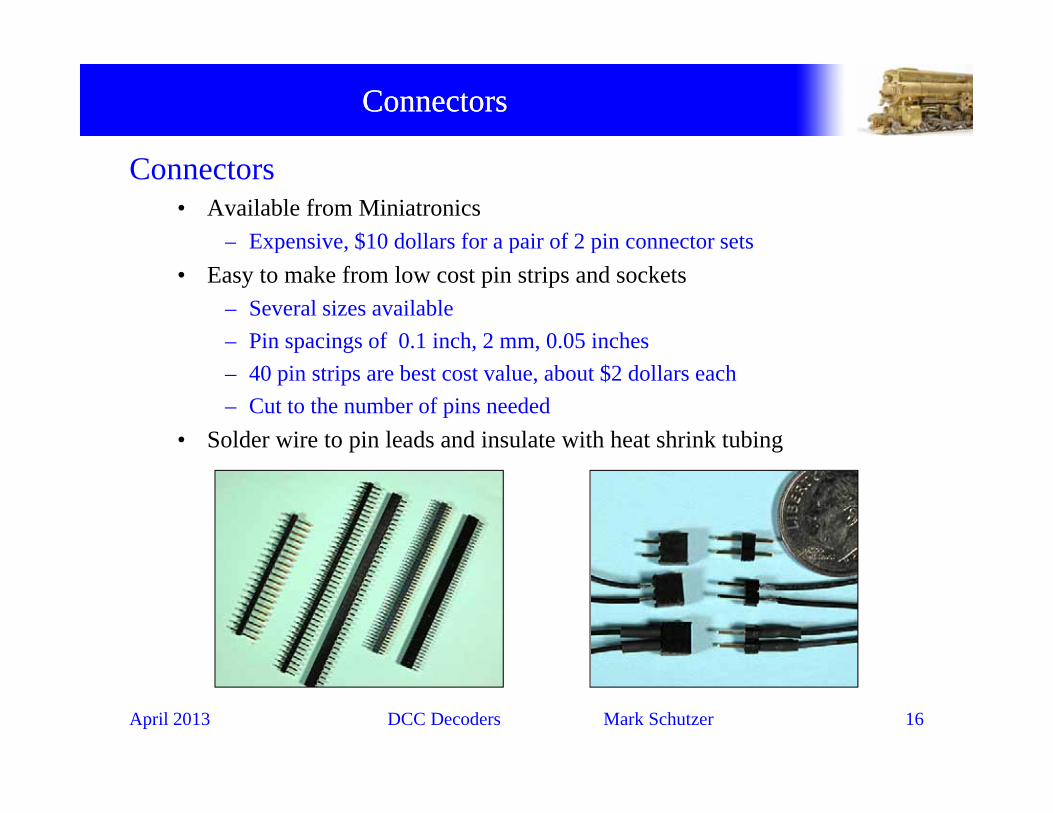
Decoder Installation ExampleDecoder Installation Example
Decoder Installation – Max Gray, Ten Wheeler
April 2013 DCC Decoders Mark Schutzer 18

Boiler RemovalBoiler Removal
Removing the boiler• The boiler is usually secured to the
frame with three screws.• The front screw usually also
secures the pilot trucks in place.• The two rear screws are eitherThe two rear screws are either
under the cab, or in this case in the back wall of the cab.
• Remove the two cab screws andRemove the two cab screws and the pilot truck mounting stud to loosen the boiler.
April 2013 DCC Decoders Mark Schutzer 19

Boiler RemovedBoiler Removed
Boiler Removed• Note motor wiring, identify right
and left rail connections.
• Note headlight connector.
April 2013 DCC Decoders Mark Schutzer 20

Decoder FittingDecoder Fitting
Test fit selected decoder• Decoder N14SR• Test fit decoder to determineTest fit decoder to determine
ideal position.• Usually place decoder on top of
motormotor.• With decoder in place verify
boiler clearance, adjust location as neededas needed.
April 2013 DCC Decoders Mark Schutzer 21
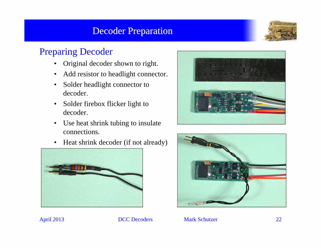
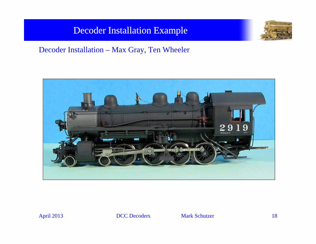
Decoder PreparationDecoder Preparation
Preparing Decoder• Original decoder shown to right.• Add resistor to headlight connector.g• Solder headlight connector to
decoder.• Solder firebox flicker light to
decoder. • Use heat shrink tubing to insulate
connections.h i k d d (if l d )• Heat shrink decoder (if not already)
April 2013 DCC Decoders Mark Schutzer 22

Motor WiringMotor Wiring
Wiring Motor Connections• Reference original motor connections.• Connect red wire to right side pickupConnect red wire to right side pickup
(locomotive frame).• Connect orange wire to the motor
terminal that was connected to the rightterminal that was connected to the right side rail (frame connection).
• Connect black wire to the tender drawbardrawbar.
• Connect grey wire to the motor terminal that was connected to the tender drawbardrawbar.
April 2013 DCC Decoders Mark Schutzer 23

InstallingInstalling
Secure decoder with Kapton tape or electrical tape.Place firebox flicker light in position.Test first on programming track, and then on main.Reinstall boiler to complete.pRecheck operation.
April 2013 DCC Decoders Mark Schutzer 24

Diesel Installation ExampleDiesel Installation Example

Decoder Installation Example Decoder Installation Example -- DieselDiesel
Decoder Installation – Stewart – F7
April 2013 DCC Decoders Mark Schutzer 26

Shell RemovalShell Removal
Removing the shell• Remove the front coupler retainer and remove the front• Remove the front coupler retainer and remove the front
coupler.
G l h h ll l h b d• Gently pry the shell apart along the bottom and remove the shell.
April 2013 DCC Decoders Mark Schutzer 27

Wiring Board RemovalWiring Board Removal
Wiring Board Removal• Remove 2 screws, unplug all the connectors• Slip motor connections from underneath retainer wiresSlip motor connections from underneath retainer wires• Remove board and discard
April 2013 DCC Decoders Mark Schutzer 28
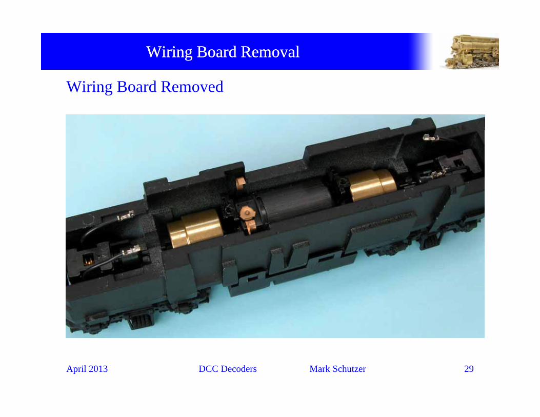
Wiring Board RemovalWiring Board Removal
Wiring Board Removed
April 2013 DCC Decoders Mark Schutzer 29

Decoder FeaturesDecoder Features
NCE DASR
April 2013 DCC Decoders Mark Schutzer 30

Decoder SelectionDecoder Selection
Connection diagram• NCE DASR• Connection diagram shown belowConnection diagram shown below.
April 2013 DCC Decoders Mark Schutzer 31

Decoder FittingDecoder Fitting
Fit selected decoder• Decoder NCE DASR, or any Atlas form factor decoder• Use original screws to secureUse original screws to secure• Solder motor tabs to traces on board.• Solder wire extensions to truck pickup wires
April 2013 DCC Decoders Mark Schutzer 32

Decoder FittingDecoder Fitting
Fitting decoder• Apply heat shrink tubing over exposed wires before
solderingg• Solder pickup wire connections in place
April 2013 DCC Decoders Mark Schutzer 33

LightingLighting
Prepare lighting• A 3mm golden white LED will be used for the upper
headlight. Solder a 1000 ohm 1/4W limiting resistor in line g gas shown.
• For the lower headlight a 0603 surface mount golden white LED will be used. Shown on a small circuit board with 1000 ohm limiting resistor.
April 2013 DCC Decoders Mark Schutzer 34

LightingLighting
Upper headlight• Solder 3mm LED and resistor to the pads on the end of the
decoder as shown.• Anode, or positive side of LED goes to the common pad (C).
April 2013 DCC Decoders Mark Schutzer 35

LightingLighting
Lower headlight• Secure circuit board in place with
double sided foam tapep• Run wires to decoder output #3 and the
other common terminal
April 2013 DCC Decoders Mark Schutzer 36

Reinstall ShellReinstall Shell
• Reinstall the shell, program, and enjoy your new DCC locomotive.
• LED headlights in the finished installation shown below…
April 2013 DCC Decoders Mark Schutzer 37

Sound in Steam LocomotivesSound in Steam Locomotives
Sound Decoders• Sound decoders, Soundtraxx Tsunami, Best in class sound with
silent BEMF motor control.• Installation the same as a regular decoder but with more wires
– Two additional wires to connect to speakerOne wire for optional synchronization cam– One wire for optional synchronization cam
• Speaker usually mounted in tender– Requires holes to be drilled in tender frame or body
T d h ll h k l– Tender shell can act as the speaker enclosure – Two wire connector between locomotive and tender
• Optimal chuff synchronization requires a sound cam
April 2013 DCC Decoders Mark Schutzer 38

Sound Decoder InstallationSound Decoder Installation
Tsunami in Boiler
• Decoder tucked up above boiler weightg
April 2013 DCC Decoders Mark Schutzer 39

Sound Decoder InstallationSound Decoder Installation
Micro Tsunami in a Consolidation• Decoder tucked up above boiler
weightg
April 2013 DCC Decoders Mark Schutzer 40

Sound Decoder InstallationSound Decoder Installation
Micro Tsunami in a Consolidation• Keep alive caps in tender
• Speaker in smoke box
April 2013 DCC Decoders Mark Schutzer 41

Sound InstallationSound Installation
Additional Sound work• Sound cams
• Sound cam installation• Make wiper from small circuitMake wiper from small circuit
board, use phosphor bronze wire for contact
April 2013 DCC Decoders Mark Schutzer 42

Sound InstallationSound Installation
Other Sound Cam options• Soundtraxx printed circuit
board cams
• Grizzly Mountain Engineering Cams, split cams that attached
i h d i iwith conductive Epoxy, wiper kits also available
• No driver pulling required with these cams
April 2013 DCC Decoders Mark Schutzer 43
these cams

Sound InstallationSound Installation
Speaker installation• Usually installed in tender
• Requires drilling hole pattern in tender for sound outlet
• Use the biggest speaker that will fit!
April 2013 DCC Decoders Mark Schutzer 44
will fit!

Sound InstallationSound Installation
Speakers• Another example.
• Small speakers allow for mounting in the boiler.
April 2013 DCC Decoders Mark Schutzer 45

Sound in Diesel LocomotivesSound in Diesel Locomotives
Sound Decoders• Sound decoders, Soundtraxx Tsunami, QSI, MRC, Digitrax, lots of
choices. Tsunami and QSI are the best qualityQ q y• Installation the same as a regular decoder but with more wires
– Two additional wires to connect to speaker• Speaker usually requires some frame modifications• Speaker usually requires some frame modifications
– Speaker enclosure is Very important for proper sound levels
April 2013 DCC Decoders Mark Schutzer 46

Sound in Diesel LocomotivesSound in Diesel Locomotives
Tsunami installation in a Proto 2k• Original light board removed and prepared for decoder installation
April 2013 DCC Decoders Mark Schutzer 47

Sound in Diesel LocomotivesSound in Diesel Locomotives
Test fitting the speaker • Speaker mounting shown
April 2013 DCC Decoders Mark Schutzer 48

Sound in Diesel LocomotivesSound in Diesel Locomotives
Finished installation• Decoder, speaker, and lights installed
April 2013 DCC Decoders Mark Schutzer 49

More Steam ExamplesMore Steam Examples

ExamplesExamples
Balboa MT-4, Lenz Gold decoder
April 2013 DCC Decoders Mark Schutzer 51

ExamplesExamples
Max Grey TW-8, N14SR decoder Balboa P-10 #2486, D13SRJ
Westside 0-6-0T, N14SR decoder Balboa P-10 #2486, D13SRJ
April 2013 DCC Decoders Mark Schutzer 52
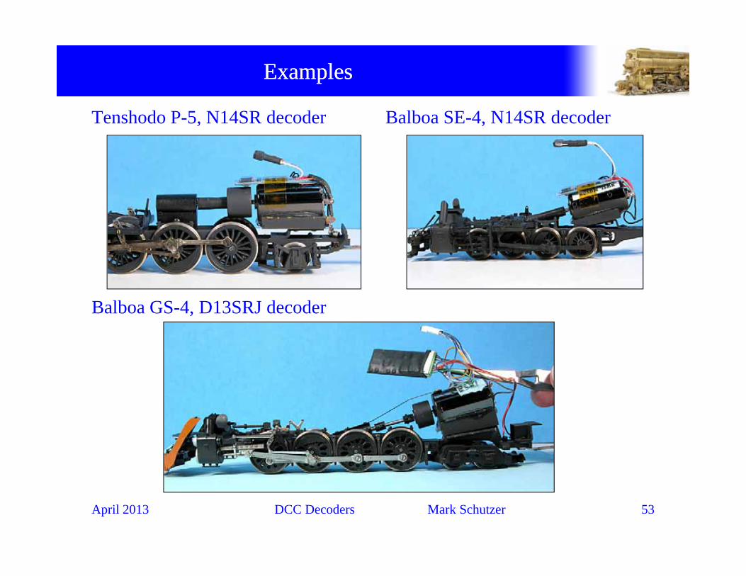
ExamplesExamples
Tenshodo P-5, N14SR decoder Balboa SE-4, N14SR decoder
Balboa GS-4, D13SRJ decoder
April 2013 DCC Decoders Mark Schutzer 53

SourcesSources

SourcesSources
Digi-Key Electronics - www.digikey.com• Resistors• Heat Shrink tubing
– Various different sizes, 3/32”, 1/16”, 1/8”, 3/16”, etc.• Pin strip headers / sockets
– 40 pin 2mm header strip, part number S5800-40-ND– 40 pin 2mm socket strip, part number S5751-40-ND
• Kapton tape• Speakers
Miniatronics - www.miniatronics.com• Miniature connectors• Various miniature bulbs 1 5 volt 12 volt and 14 volt flavorsVarious miniature bulbs, 1.5 volt, 12 volt, and 14 volt flavors
Richmond Controls - www.richmondcontrols.com • Sunny white and golden white LED’s, 3mm and 5mm diameter
April 2013 DCC Decoders Mark Schutzer 55

SourcesSources
Grizzly Mountain Engineering – www.g-m-e.com• Sound cams• Sound pickup wipersSound pickup wipers• 2 Pin strip headers / sockets• Speakers
Soundtraxx - www.soundtraxx.com• Decoders, Tsunami, Micro Tsunami, ,• PC board sound cams• Speakers
April 2013 DCC Decoders Mark Schutzer 56

Questions?
April 2013 DCC Decoders Mark Schutzer 57