99SSP_Template - Caltrans - California Department of ... · Web viewMoisture tests shall be...
159
** WARNING ** WARNING ** WARNING ** WARNING ** This document is intended for informational purposes only. Users are cautioned that California Department of Transportation (Department) does not assume any liability or responsibility based on these electronic files or for any defective or incomplete copying, exerpting, scanning, faxing or downloading of the contract documents. As always, for the official paper versions of the bidders packages and non-bidder packages, including addenda write to the California Department of Transportation, Plans and Bid Documents, Room 0200, P.O. Box 942874, Sacramento, CA 94272-0001, telephone (916) 654-4490 or fax (916) 654-7028. Office hours are 7:30 a.m. to 4:15 p.m. When ordering bidder or non-bidder packages it is important that you include a telephone number and fax number, P.O. Box and street address so that you can receive addenda. etric Caltrans
Transcript of 99SSP_Template - Caltrans - California Department of ... · Web viewMoisture tests shall be...

** WARNING ** WARNING ** WARNING ** WARNING **This document is intended for informational purposes only.
Users are cautioned that California Department of Transportation (Department) does not assume any liability or responsibility based on these electronic files or for any defective or incomplete copying, exerpting, scanning, faxing or downloading of the contract documents. As always, for the official paper versions of the bidders packages and non-bidder packages, including addenda write to the California Department of Transportation, Plans and Bid Documents, Room 0200, P.O. Box 942874, Sacramento, CA 94272-0001, telephone (916) 654-4490 or fax (916) 654-7028. Office hours are 7:30 a.m. to 4:15 p.m. When ordering bidder or non-bidder packages it is important that you include a telephone number and fax number, P.O. Box and street address so that you can receive addenda.
etric
Caltrans
STATE OF CALIFORNIA
DEPARTMENT OF TRANSPORTATION__________________________________________________________
NOTICE TO CONTRACTORSAND
SPECIAL PROVISIONSFOR CONSTRUCTION ON STATE HIGHWAY IN ORANGE COUNTY IN TUSTIN AND SANTA ANA FROM 48.6 km NORTH OF
THE 5 / 55 SEPARATION TO 55.4 km NORTH OF THE 5 / 22 SEPARATION
DISTRICT 12, ROUTE 5
__________________________________________________________
For Use in Connection with Standard Specifications Dated JULY 1999, Standard Plans Dated JULY 1999, and Labor Surcharge and Equipment Rental Rates.
__________________________________________________________

CONTRACT NO. 12-0A7904
12-Ora-5 -48.6/55.4
Bids Open: November 29, 2001Dated: October 29, 2001

*************************************************************************************************
IMPORTANTSPECIAL NOTICES
*************************************************************************************************
Payment BondsAttention is directed to Section 5 of the Special Provisions, regarding contract bonds. The payment bond shall be in a sum not less than one hundred percent of the total amount payable by the terms of the contract.

TABLE OF CONTENTS
NOTICE TO CONTRACTORS.............................................................................................................................................1COPY OF ENGINEER'S ESTIMATE..................................................................................................................................3SPECIAL PROVISIONS.......................................................................................................................................................5SECTION 1. SPECIFICATIONS AND PLANS..................................................................................................................5SECTION 2. PROPOSAL REQUIREMENTS AND CONDITIONS..................................................................................5
2-1.01 GENERAL..........................................................................................................................................................52-1.02 DISABLED VETERAN BUSINESS ENTERPRISE (DVBE)..........................................................................52-1.03 DVBE GOAL FOR THIS PROJECT.................................................................................................................62-1.04 SUBMISSION OF DVBE INFORMATION.....................................................................................................62-1.05 SMALL BUSINESS PREFERENCE.................................................................................................................72-1.06 CALIFORNIA COMPANY PREFERENCE.....................................................................................................8
SECTION 3. AWARD AND EXECUTION OF CONTRACT............................................................................................8SECTION 4. BEGINNING OF WORK, TIME OF COMPLETION AND LIQUIDATED DAMAGES...........................9SECTION 5. GENERAL......................................................................................................................................................9SECTION 5-1. MISCELLANEOUS....................................................................................................................................9
5-1.01 PLANS AND WORKING DRAWINGS...........................................................................................................95-1.011 EXAMINATION OF PLANS, SPECIFICATIONS, CONTRACT, AND SITE OF WORK.........................95-1.012 DIFFERING SITE CONDITIONS.................................................................................................................105-1.015 LABORATORY.............................................................................................................................................105-1.017 CONTRACT BONDS....................................................................................................................................105-1.018 EXCAVATION SAFETY PLANS................................................................................................................105-1.019 COST REDUCTION INCENTIVE................................................................................................................115-1.02 LABOR NONDISCRIMINATION..................................................................................................................115-1.03 INTEREST ON PAYMENTS..........................................................................................................................115-1.031 FINAL PAYMENT AND CLAIMS..............................................................................................................115-1.04 PUBLIC SAFETY............................................................................................................................................125-1.05 SURFACE MINING AND RECLAMATION ACT........................................................................................135-1.06 REMOVAL OF ASBESTOS AND HAZARDOUS SUBSTANCES..............................................................135-1.07 YEAR 2000 COMPLIANCE...........................................................................................................................135-1.08 SUBCONTRACTOR AND DVBE RECORDS..............................................................................................145-1.086 PERFORMANCE OF DVBE SUBCONTRACTORS AND SUPPLIERS...................................................145-1.09 SUBCONTRACTING......................................................................................................................................145-1.10 PROMPT PROGRESS PAYMENT TO SUBCONTRACTORS....................................................................155-1.11 AREAS FOR CONTRACTOR'S USE.............................................................................................................155-1.12 PAYMENTS.....................................................................................................................................................155-1.13 SOUND CONTROL REQUIREMENTS.........................................................................................................15
SECTION 6. (BLANK).......................................................................................................................................................15SECTION 7. (BLANK).......................................................................................................................................................15SECTION 8. MATERIALS................................................................................................................................................15SECTION 8-1. MISCELLANEOUS..................................................................................................................................15
8-1.01 SUBSTITUTION OF NON-METRIC MATERIALS AND PRODUCTS......................................................158-1.02 PREQUALIFIED AND TESTED SIGNING AND DELINEATION MATERIALS.....................................218-1.03 SLAG AGGREGATE......................................................................................................................................268-1.04 MISCELLANEOUS METAL..........................................................................................................................28
SECTION 8-2. CONCRETE...............................................................................................................................................298-2.01 PORTLAND CEMENT CONCRETE.............................................................................................................29
SECTION 8-3. (BLANK)...................................................................................................................................................31SECTION 9. (BLANK).......................................................................................................................................................31SECTION 10. CONSTRUCTION DETAILS....................................................................................................................31SECTION 10-1. GENERAL...............................................................................................................................................31
10-1.01 WATER POLLUTION CONTROL...............................................................................................................31WATER POLLUTION CONTROL PROGRAM PREPARATION, APPROVAL AND UPDATES.................32WPCP IMPLEMENTATION................................................................................................................................33MAINTENANCE..................................................................................................................................................33
Contract No. 12-0A79041

PAYMENT............................................................................................................................................................3410-1.02 PROGRESS SCHEDULE..............................................................................................................................3410-1.03 OBSTRUCTIONS..........................................................................................................................................3410-1.04 MOBILIZATION...........................................................................................................................................3410-1.05 CONSTRUCTION AREA TRAFFIC CONTROL DEVICES......................................................................3410-1.06 CONSTRUCTION AREA SIGNS.................................................................................................................3510-1.07 MAINTAINING TRAFFIC............................................................................................................................3510-1.08 CLOSURE REQUIREMENTS AND CONDITIONS...................................................................................39
CLOSURE SCHEDULE.......................................................................................................................................39CONTINGENCY PLAN.......................................................................................................................................39LATE REOPENING OF CLOSURES..................................................................................................................39COMPENSATION................................................................................................................................................39
10-1.09 TRAFFIC CONTROL SYSTEM FOR LANE CLOSURE............................................................................3910-1.10 PORTABLE CHANGEABLE MESSAGE SIGN..........................................................................................4010-1.11 TEMPORARY CRASH CUSHION MODULE............................................................................................40
SECTION 10-2. (BLANK).................................................................................................................................................41SECTION 10-3. COMMUNICATION AND ELECTRICAL SYSTEMS.........................................................................41
10-3.01 DESCRIPTION..............................................................................................................................................4110-3.02 COST BREAK-DOWN..................................................................................................................................4210-3.03 EQUIPMENT LIST AND DRAWINGS........................................................................................................4210-3.04 MAINTAINING EXISTING AND TEMPORARY ELECTRICAL SYSTEMS..........................................4210-3.05 CONDUIT......................................................................................................................................................42
WARNING TAPE.................................................................................................................................................43COLORED CONCRETE BACKFILL..................................................................................................................43
10-3.06 INNERDUCT.................................................................................................................................................4310-3.07 CONDUIT AND INNERDUCT SEALING PLUGS.....................................................................................4410-3.08 PULL BOXES................................................................................................................................................4410-3.09 SPLICE VAULTS..........................................................................................................................................4410-3.10 PAYMENT.....................................................................................................................................................44
SECTION 10-4. COMMUNICATIONS CABLE PLANT.................................................................................................4510-4.01 FIBER OPTICS CABLE................................................................................................................................4510-4.02 FIBER OPTIC GLOSSARY..........................................................................................................................45
DEFINITIONS.......................................................................................................................................................4510-4.03 FIBER OPTIC OUTSIDE PLANT CABLE..................................................................................................46
GENERAL.............................................................................................................................................................46FIBER CHARACTERISTICS...............................................................................................................................47COLOR CODING.................................................................................................................................................48CABLE CONSTRUCTION...................................................................................................................................48GENERAL CABLE PERFORMANCE SPECIFICATIONS...............................................................................49PACKAGING AND SHIPPING REQUIREMENTS...........................................................................................50
10-4.04 CABLE INSTALLATION.............................................................................................................................5010-4.05 SPLICING......................................................................................................................................................5110-4.06 FIBER OPTIC SPLICE CLOSURE...............................................................................................................51
SPLICE CLOSURES.............................................................................................................................................51SPLICE TRAYS....................................................................................................................................................52
10-4.07 PASSIVE CABLE ASSEMBLIES AND COMPONENTS...........................................................................5310-4.08 FIBER OPTIC CABLE LABELING.............................................................................................................5310-4.09 FIBER OPTIC CABLE TERMINATIONS...................................................................................................56
DISTRIBUTION BREAKOUT.............................................................................................................................57DISTRIBUTION INTERCONNECT PACKAGE................................................................................................57FIBER OPTIC CABLE ASSEMBLIES AND PIGTAILS....................................................................................57
10-4.10 FIBER DISTRIBUTION UNIT.....................................................................................................................5810-4.11 FAN OUT TERMINATION..........................................................................................................................5810-4.12 FIBER OPTIC CABLE TESTING.................................................................................................................5910-4.13 PAYMENT.....................................................................................................................................................59
SECTION 10-5. (BLANK).................................................................................................................................................59SECTION 10-6. COMMUNICATION SYSTEM..............................................................................................................59
10-6.01 GENERAL......................................................................................................................................................59
Contract No. 12-0A79042

10-6.02 INTERFACE TO EXISTING TRAFFIC ELEMENTS.................................................................................5910-6.03 INTERFACE TO EXISTING CLOSED CIRCUIT TELEVISION...............................................................6010-6.04 EQUIPMENT AT EXISTING CABLE NODE.............................................................................................6010-6.05 EQUIPMENT AT EXISTING HUB #1 (ROUTE 5/57/22 INTERCHANGE)...................................................6010-6.06 VIDEO TRANSMITTER AND VIDEO RECEIVER...................................................................................6110-6.07 FIBER OPTIC DATA MODEM....................................................................................................................6210-6.08 TIME DIVISION MULTIPLEXER...............................................................................................................6310-6.09 PAYMENT.....................................................................................................................................................64
SECTION 10-7. COMMUNICATION SYSTEM CUTOVER..........................................................................................6410-7.01 DESCRIPTION..............................................................................................................................................6410-7.02 CHANGEABLE MESSAGE SIGN RESTRICTIONS..................................................................................6510-7.03 TRAFFIC SIGNAL, RAMP METERING AND SURVEILLANCE CONTROLLER RESTRICTIONS....6510-7.04 PAYMENT.....................................................................................................................................................65
SECTION 10-8. SYSTEM TESTING AND DOCUMENTATION..................................................................................6510-8.01 DESCRIPTION..............................................................................................................................................6510-8.02 PRE-INSTALLATION TESTING.................................................................................................................6510-8.03 SUBSYSTEM TESTING...............................................................................................................................6610-8.04 FIBER OPTIC TESTING...............................................................................................................................66
GENERAL.............................................................................................................................................................66FACTORY TESTING...........................................................................................................................................66AFTER CABLE INSTALLATION.......................................................................................................................67OUTDOOR SPLICES...........................................................................................................................................67DISTRIBUTION INTERCONNECT PACKAGE TESTING AND DOCUMENTATION................................67FIBER OPTIC SYSTEM GAIN MARGIN...........................................................................................................67ACTIVE COMPONENT TESTING.....................................................................................................................67SYSTEM VERIFICATION AT COMPLETION..................................................................................................67
10-8.05 VIDEO LINK TESTING................................................................................................................................7210-8.06 DATA LINK TESTING.................................................................................................................................7310-8.07 TIME DIVISION MULTIPLEXER TESTING.............................................................................................7310-8.08 ACCEPTANCE TESTING............................................................................................................................7410-8.09 SYSTEM DOCUMENTATION....................................................................................................................7510-8.10 PAYMENT.....................................................................................................................................................77
SECTION 11. MODIFIED STANDARD SPECIFICATION SECTIONS........................................................................77SECTION 11-1. (BLANK).................................................................................................................................................77SECTION 11-2. PORTLAND CEMENT CONCRETE.....................................................................................................77
STANDARD PLANS LIST
The Standard Plan sheets applicable to this contract include, but are not limited to those indicated below. The Revised Standard Plans (RSP) and New Standard Plans (NSP) which apply to this contract are included as individual sheets of the project plans.
A10A AbbreviationsA10B SymbolsA73B MarkersRSP T2 Temporary Crash Cushion, Sand Filled (Shoulder Installations)T10 Traffic Control System for Lane Closure On Freeways and ExpresswaysT14 Traffic Control System for Ramp ClosureES-1A Signal, Lighting and Electrical Systems - Symbols and AbbreviationsES-1B Signal, Lighting and Electrical Systems - Symbols and AbbreviationsES-8 Signal, Lighting and Electrical Systems - Pull Box Details
Contract No. 12-0A79043

Contract No. 12-0A79044

State Project with DVBE Goals (06-14-00)
DEPARTMENT OF TRANSPORTATION_________________________
NOTICE TO CONTRACTORS
_________________________
CONTRACT NO. 12-0A7904
12-Ora-5 -48.6/55.4
Sealed proposals for the work shown on the plans entitled:
STATE OF CALIFORNIA; DEPARTMENT OF TRANSPORTATION; PROJECT PLANS FOR CONSTRUCTION ON STATE HIGHWAY IN ORANGE COUNTY IN TUSTIN AND SANTA ANA FROM 48.6 km NORTH OF
THE 5 / 55 SEPARATION TO 55.4 km NORTH OF THE 5 / 22 SEPARATION
will be received at the Department of Transportation, 3347 Michelson Drive, Suite 100, Irvine, CA 92612-1692, until 2 o'clock p.m. on November 29, 2001, at which time they will be publicly opened and read in Room C - 1116 at the same address.
Proposal forms for this work are included in a separate book entitled:
STATE OF CALIFORNIA; DEPARTMENT OF TRANSPORTATION; PROPOSAL AND CONTRACT FOR CONSTRUCTION ON STATE HIGHWAY IN ORANGE COUNTY IN TUSTIN AND SANTA ANA FROM
48.6 km NORTH OF THE 5 / 55 SEPARATION TO 55.4 km NORTH OF THE 5 / 22 SEPARATION
General work description: FIBER OPTICS COMMUNICATION SYSTEM.
This project has a goal of 3 percent disabled veteran business enterprise (DVBE) participation.No prebid meeting is scheduled for this project.Bids are required for the entire work described herein.At the time this contract is awarded, the Contractor shall possess either a Class A license or one of the following Class C
licenses: C-10.The Contractor must also be properly licensed at the time the bid is submitted, except that on a joint venture bid a joint
venture license may be obtained by a combination of licenses after bid opening but before award in conformance with Business and Professions Code, Section 7029.1.
This contract is subject to state contract nondiscrimination and compliance requirements pursuant to Government Code, Section 12990.
Preference will be granted to bidders properly certified as a "Small Business" as determined by the Department of General Services, Office of Small Business Certification and Resources at the time of bid opening in conformance with the provisions in Section 2-1.05, "Small Business Preference," of the special provisions, and Section 1896 et seq, Title 2, California Code of Regulations. A form for requesting a "Small Business" preference is included with the bid documents. Applications for status as a "Small Business" must be submitted to the Department of General Services, Office of Small Business Certification and Resources, 1531 "I" Street, Second Floor, Sacramento, CA 95814, Telephone No. (916) 322-5060.
A reciprocal preference will be granted to "California company" bidders in conformance with Section 6107 of the Public Contract Code. (See Sections 2 and 3 of the special provisions.) A form for indicating whether bidders are or are not a "California company" is included in the bid documents and is to be filled in and signed by all bidders.
Contract No. 12-0A79041

Project plans, special provisions, and proposal forms for bidding this project can only be obtained at the Department of Transportation, Plans and Bid Documents, Room 0200, MS #26, Transportation Building, 1120 N Street, Sacramento, California 95814, FAX No. (916) 654-7028, Telephone No. (916) 654-4490. Use FAX orders to expedite orders for project plans, special provisions and proposal forms. FAX orders must include credit card charge number, card expiration date and authorizing signature. Project plans, special provisions, and proposal forms may be seen at the above Department of Transportation office and at the offices of the District Directors of Transportation at Irvine, Oakland, and the district in which the work is situated. Standard Specifications and Standard Plans are available through the State of California, Department of Transportation, Publications Unit, 1900 Royal Oaks Drive, Sacramento, CA 95815, Telephone No. (916) 445-3520.
Cross sections for this project are not available.The successful bidder shall furnish a payment bond and a performance bond.Pursuant to Section 1773 of the Labor Code, the general prevailing wage rates in the county, or counties, in which the
work is to be done have been determined by the Director of the California Department of Industrial Relations. These wages are set forth in the General Prevailing Wage Rates for this project, available at the Labor Compliance Office at the offices of the District Director of Transportation for the district in which the work is situated, and available from the California Department of Industrial Relations’ Internet Web Site at: http://www.dir.ca.gov. Future effective general prevailing wage rates which have been predetermined and are on file with the Department of Industrial Relations are referenced but not printed in the general prevailing wage rates.
DEPARTMENT OF TRANSPORTATION
Deputy Director Transportation Engineering
Dated October 29, 2001
AKC
Contract No. 12-0A79042

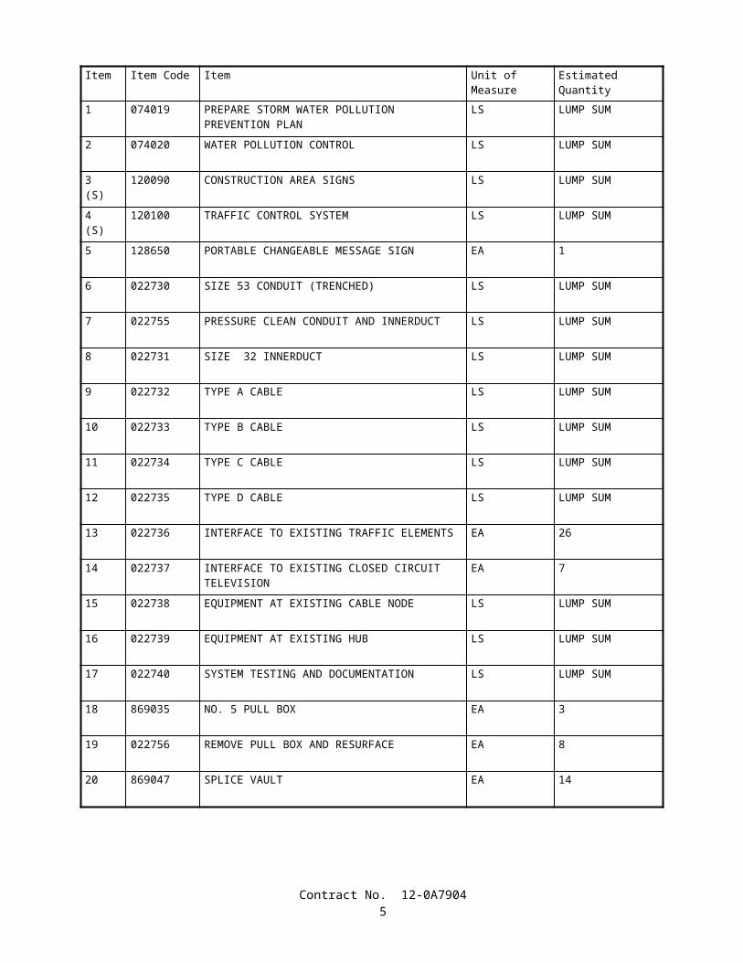
COPY OF ENGINEER'S ESTIMATE
(NOT TO BE USED FOR BIDDING PURPOSES)
12-0A7904
Item Item Code Item Unit of Measure Estimated Quantity
1 074019 PREPARE STORM WATER POLLUTION PREVENTION PLAN
LS LUMP SUM
2 074020 WATER POLLUTION CONTROL LS LUMP SUM
3(S)
120090 CONSTRUCTION AREA SIGNS LS LUMP SUM
4(S)
120100 TRAFFIC CONTROL SYSTEM LS LUMP SUM
5 128650 PORTABLE CHANGEABLE MESSAGE SIGN EA 1
6 022730 SIZE 53 CONDUIT (TRENCHED) LS LUMP SUM
7 022755 PRESSURE CLEAN CONDUIT AND INNERDUCT LS LUMP SUM
8 022731 SIZE 32 INNERDUCT LS LUMP SUM
9 022732 TYPE A CABLE LS LUMP SUM
10 022733 TYPE B CABLE LS LUMP SUM
11 022734 TYPE C CABLE LS LUMP SUM
12 022735 TYPE D CABLE LS LUMP SUM
13 022736 INTERFACE TO EXISTING TRAFFIC ELEMENTS EA 26
14 022737 INTERFACE TO EXISTING CLOSED CIRCUIT TELEVISION
EA 7
15 022738 EQUIPMENT AT EXISTING CABLE NODE LS LUMP SUM
16 022739 EQUIPMENT AT EXISTING HUB LS LUMP SUM
17 022740 SYSTEM TESTING AND DOCUMENTATION LS LUMP SUM
18 869035 NO. 5 PULL BOX EA 3
19 022756 REMOVE PULL BOX AND RESURFACE EA 8
20 869047 SPLICE VAULT EA 14
Contract No. 12-0A79043

Item Item Code Item Unit of Measure Estimated Quantity
21 022741 FIBER OPTIC SPLICE CLOSURE EA 14
22 999990 MOBILIZATION LS LUMP SUM
Contract No. 12-0A79044
STATE OF CALIFORNIA
DEPARTMENT OF TRANSPORTATION
_____________________________
SPECIAL PROVISIONS
Annexed to Contract No. 12-0A7904
SECTION 1. SPECIFICATIONS AND PLANSThe work embraced herein shall conform to the provisions in the Standard Specifications dated July 1999, and the
Standard Plans dated July 1999, of the Department of Transportation insofar as the same may apply, and these special provisions.
Amendments to the Standard Specifications set forth in these special provisions shall be considered as part of the Standard Specifications for the purposes set forth in Section 5-1.04, "Coordination and Interpretation of Plans, Standard Specifications and Special Provisions," of the Standard Specifications. Whenever either the term "Standard Specifications is amended" or the term "Standard Specifications are amended" is used in the special provisions, the indented text or table following the term shall be considered an amendment to the Standard Specifications. In case of conflict between such amendments and the Standard Specifications, the amendments shall take precedence over and be used in lieu of the conflicting portions.
In case of conflict between the Standard Specifications and these special provisions, the special provisions shall take precedence over and shall be used in lieu of the conflicting portions.
SECTION 2. PROPOSAL REQUIREMENTS AND CONDITIONS2-1.01 GENERAL
The bidder's attention is directed to the provisions in Section 2, "Proposal Requirements and Conditions," of the Standard Specifications and these special provisions for the requirements and conditions which the bidder must observe in the preparation of the proposal form and the submission of the bid.
In addition to the subcontractors required to be listed in conformance with Section 2-1.054, "Required Listing of Proposed Subcontractors," of the Standard Specifications, each proposal shall have listed therein the name and address of each DVBE subcontractor to be used for credit in meeting the goal, and to whom the bidder proposes to directly subcontract portions of the work. The list of subcontractors shall also set forth the portion of work that will be performed by each subcontractor listed. A sheet for listing the subcontractors is included in the Proposal.
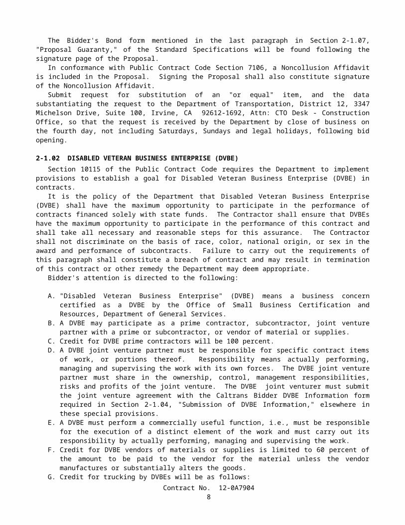
The Bidder's Bond form mentioned in the last paragraph in Section 2-1.07, "Proposal Guaranty," of the Standard Specifications will be found following the signature page of the Proposal.
In conformance with Public Contract Code Section 7106, a Noncollusion Affidavit is included in the Proposal. Signing the Proposal shall also constitute signature of the Noncollusion Affidavit.
Submit request for substitution of an "or equal" item, and the data substantiating the request to the Department of Transportation, District 12, 3347 Michelson Drive, Suite 100, Irvine, CA 92612-1692, Attn: CTO Desk - Construction Office, so that the request is received by the Department by close of business on the fourth day, not including Saturdays, Sundays and legal holidays, following bid opening.
2-1.02 DISABLED VETERAN BUSINESS ENTERPRISE (DVBE)Section 10115 of the Public Contract Code requires the Department to implement provisions to establish a goal for
Disabled Veteran Business Enterprise (DVBE) in contracts.It is the policy of the Department that Disabled Veteran Business Enterprise (DVBE) shall have the maximum
opportunity to participate in the performance of contracts financed solely with state funds. The Contractor shall ensure that DVBEs have the maximum opportunity to participate in the performance of this contract and shall take all necessary and reasonable steps for this assurance. The Contractor shall not discriminate on the basis of race, color, national origin, or sex in the award and performance of subcontracts. Failure to carry out the requirements of this paragraph shall constitute a breach of contract and may result in termination of this contract or other remedy the Department may deem appropriate.
Bidder's attention is directed to the following:
Contract No. 12-0A79045

A. "Disabled Veteran Business Enterprise" (DVBE) means a business concern certified as a DVBE by the Office of Small Business Certification and Resources, Department of General Services.
B. A DVBE may participate as a prime contractor, subcontractor, joint venture partner with a prime or subcontractor, or vendor of material or supplies.
C. Credit for DVBE prime contractors will be 100 percent.D. A DVBE joint venture partner must be responsible for specific contract items of work, or portions thereof.
Responsibility means actually performing, managing and supervising the work with its own forces. The DVBE joint venture partner must share in the ownership, control, management responsibilities, risks and profits of the joint venture. The DVBE joint venturer must submit the joint venture agreement with the Caltrans Bidder DVBE Information form required in Section 2-1.04, "Submission of DVBE Information," elsewhere in these special provisions.
E. A DVBE must perform a commercially useful function, i.e., must be responsible for the execution of a distinct element of the work and must carry out its responsibility by actually performing, managing and supervising the work.
F. Credit for DVBE vendors of materials or supplies is limited to 60 percent of the amount to be paid to the vendor for the material unless the vendor manufactures or substantially alters the goods.
G. Credit for trucking by DVBEs will be as follows:
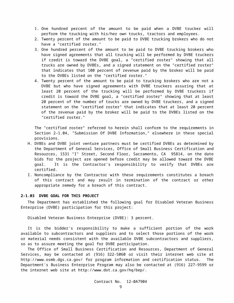
1. One hundred percent of the amount to be paid when a DVBE trucker will perform the trucking with his/her own trucks, tractors and employees.
2. Twenty percent of the amount to be paid to DVBE trucking brokers who do not have a "certified roster."3. One hundred percent of the amount to be paid to DVBE trucking brokers who have signed agreements that all
trucking will be performed by DVBE truckers if credit is toward the DVBE goal, a "certified roster" showing that all trucks are owned by DVBEs, and a signed statement on the "certified roster" that indicates that 100 percent of revenue paid by the broker will be paid to the DVBEs listed on the "certified roster."
4. Twenty percent of the amount to be paid to trucking brokers who are not a DVBE but who have signed agreements with DVBE truckers assuring that at least 20 percent of the trucking will be performed by DVBE truckers if credit is toward the DVBE goal, a "certified roster" showing that at least 20 percent of the number of trucks are owned by DVBE truckers, and a signed statement on the "certified roster" that indicates that at least 20 percent of the revenue paid by the broker will be paid to the DVBEs listed on the "certified roster."
The "certified roster" referred to herein shall conform to the requirements in Section 2-1.04, "Submission Of DVBE Information," elsewhere in these special provisions.
H. DVBEs and DVBE joint venture partners must be certified DVBEs as determined by the Department of General Services, Office of Small Business Certification and Resources, 1531 "I" Street, Second Floor, Sacramento, CA 95814, on the date bids for the project are opened before credit may be allowed toward the DVBE goal. It is the Contractor's responsibility to verify that DVBEs are certified.
I. Noncompliance by the Contractor with these requirements constitutes a breach of this contract and may result in termination of the contract or other appropriate remedy for a breach of this contract.
2-1.03 DVBE GOAL FOR THIS PROJECTThe Department has established the following goal for Disabled Veteran Business Enterprise (DVBE) participation for
this project:
Disabled Veteran Business Enterprise (DVBE): 3 percent.
It is the bidder's responsibility to make a sufficient portion of the work available to subcontractors and suppliers and to select those portions of the work or material needs consistent with the available DVBE subcontractors and suppliers, so as to assure meeting the goal for DVBE participation.
The Office of Small Business Certification and Resources, Department of General Services, may be contacted at (916) 322-5060 or visit their internet web site at http://www.osmb.dgs.ca.gov/ for program information and certification status. The Department's Business Enterprise Program may also be contacted at (916) 227-9599 or the internet web site at http://www.dot.ca.gov/hq/bep/.
Contract No. 12-0A79046

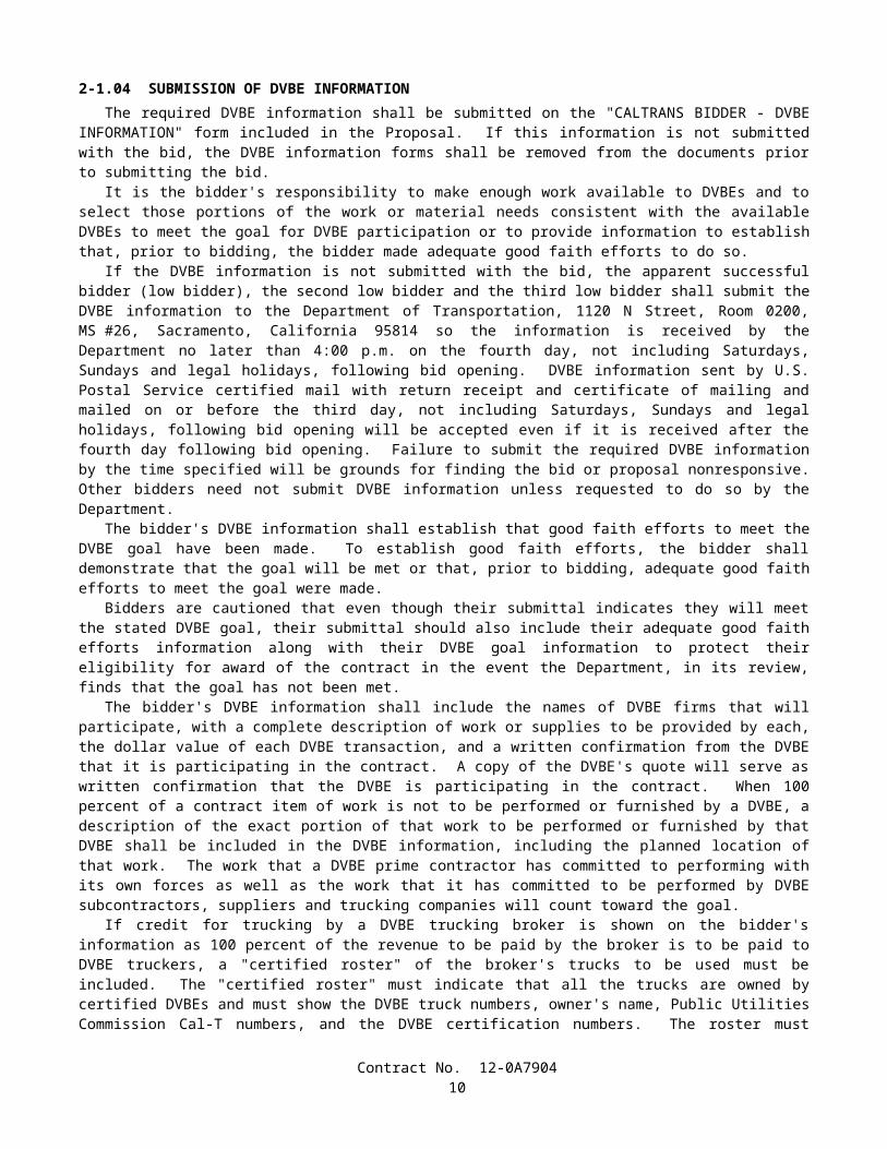
2-1.04 SUBMISSION OF DVBE INFORMATIONThe required DVBE information shall be submitted on the "CALTRANS BIDDER - DVBE INFORMATION" form
included in the Proposal. If this information is not submitted with the bid, the DVBE information forms shall be removed from the documents prior to submitting the bid.
It is the bidder's responsibility to make enough work available to DVBEs and to select those portions of the work or material needs consistent with the available DVBEs to meet the goal for DVBE participation or to provide information to establish that, prior to bidding, the bidder made adequate good faith efforts to do so.
If the DVBE information is not submitted with the bid, the apparent successful bidder (low bidder), the second low bidder and the third low bidder shall submit the DVBE information to the Department of Transportation, 1120 N Street, Room 0200, MS #26, Sacramento, California 95814 so the information is received by the Department no later than 4:00 p.m. on the fourth day, not including Saturdays, Sundays and legal holidays, following bid opening. DVBE information sent by U.S. Postal Service certified mail with return receipt and certificate of mailing and mailed on or before the third day, not including Saturdays, Sundays and legal holidays, following bid opening will be accepted even if it is received after the fourth day following bid opening. Failure to submit the required DVBE information by the time specified will be grounds for finding the bid or proposal nonresponsive. Other bidders need not submit DVBE information unless requested to do so by the Department.
The bidder's DVBE information shall establish that good faith efforts to meet the DVBE goal have been made. To establish good faith efforts, the bidder shall demonstrate that the goal will be met or that, prior to bidding, adequate good faith efforts to meet the goal were made.
Bidders are cautioned that even though their submittal indicates they will meet the stated DVBE goal, their submittal should also include their adequate good faith efforts information along with their DVBE goal information to protect their eligibility for award of the contract in the event the Department, in its review, finds that the goal has not been met.
The bidder's DVBE information shall include the names of DVBE firms that will participate, with a complete description of work or supplies to be provided by each, the dollar value of each DVBE transaction, and a written confirmation from the DVBE that it is participating in the contract. A copy of the DVBE's quote will serve as written confirmation that the DVBE is participating in the contract. When 100 percent of a contract item of work is not to be performed or furnished by a DVBE, a description of the exact portion of that work to be performed or furnished by that DVBE shall be included in the DVBE information, including the planned location of that work. The work that a DVBE prime contractor has committed to performing with its own forces as well as the work that it has committed to be performed by DVBE subcontractors, suppliers and trucking companies will count toward the goal.
If credit for trucking by a DVBE trucking broker is shown on the bidder's information as 100 percent of the revenue to be paid by the broker is to be paid to DVBE truckers, a "certified roster" of the broker's trucks to be used must be included. The "certified roster" must indicate that all the trucks are owned by certified DVBEs and must show the DVBE truck numbers, owner's name, Public Utilities Commission Cal-T numbers, and the DVBE certification numbers. The roster must indicate that all revenue paid by the broker will be paid to DVBEs listed on the "certified roster".
If credit for trucking by a trucking broker who is not a DVBE is shown in the bidder's information, a "certified roster" of the broker's trucks to be used must be included. The "certified roster" must indicate that at least 20 percent of the broker's trucks are owned by certified DVBEs and must show the DVBE truck numbers, owner's name, Public Utilities Commission Cal-T numbers, and the DVBE certification number. The roster must indicate that at least 20 percent of the revenue paid by the broker will be paid to DVBEs listed on the "certified roster".
A bidder shall be deemed to have made good faith efforts upon submittal, within time limits specified by the Department, of documentary evidence that all of the following actions were taken:
A. Contact was made with the Office of Small Business Certification and Resources (OSBCR), Department of General Services or their web site at http://www.osmb.dgs.ca.gov/ to identify Disabled Veteran Business Enterprises.
B. Advertising was published in trade media and media focusing on Disabled Veteran Business Enterprises, unless time limits imposed by the Department do not permit that advertising.
C. Invitations to bid were submitted to potential Disabled Veteran Business Enterprise contractors.D. Available Disabled Veteran Business Enterprises were considered.
2-1.05 SMALL BUSINESS PREFERENCEAttention is directed to "Award and Execution of Contract" of these special provisions.Attention is also directed to the Small Business Procurement and Contract Act, Government Code Section 14835, et seq
and Title 2, California Code of Regulations, Section 1896, et seq.Bidders who wish to be classified as a Small Business under the provisions of those laws and regulations, shall be
certified as Small Business by the Department of General Services, Office of Small Business Certification and Resources, 1531 "I" Street, Second Floor, Sacramento, CA 95814.
Contract No. 12-0A79047
To request Small Business Preference, bidders shall fill out and sign the Request for Small Business Preference form in the Proposal and shall attach a copy of their Office of Small Business Certification and Resources (OSBCR) small business certification letter to the form. The bidder's signature on the Request for Small Business Preference certifies, under penalty of perjury, that the bidder is certified as Small Business at the time of bid opening and further certifies, under penalty of perjury, that under the following conditions, at least 50 percent of the subcontractors to be utilized on the project are either certified Small Business or have applied for Small Business certification by bid opening date and are subsequently granted Small Business certification.
The conditions requiring the aforementioned 50 percent level of subcontracting by Small Business subcontractors apply if:
A. The lowest responsible bid for the project exceeds $100,000; andB. The project work to be performed requires a Class A or a Class B contractor's license; andC. Two or more subcontractors will be used.
If the above conditions apply and Small Business Preference is granted in the award of the contract, the 50 percent Small Business subcontractor utilization level shall be maintained throughout the life of the contract.
2-1.06 CALIFORNIA COMPANY PREFERENCEAttention is directed to "Award and Execution of Contract" of these special provisions.In conformance with the requirements of Section 6107 of the Public Contract Code, a "California company" will be
granted a reciprocal preference for bid comparison purposes as against a nonresident contractor from any state that gives or requires a preference to be given contractors from that state on its public entity construction contracts.
A "California company" means a sole proprietorship, partnership, joint venture, corporation, or other business entity that was a licensed California contractor on the date when bids for the public contract were opened and meets one of the following:
A. Has its principal place of business in California.B. Has its principal place of business in a state in which there is no local contractor preference on construction
contracts.C. Has its principal place of business in a state in which there is a local contractor construction preference and the
contractor has paid not less than $5000 in sales or use taxes to California for construction related activity for each of the five years immediately preceding the submission of the bid.
To carry out the "California company" reciprocal preference requirements of Section 6107 of the Public Contract Code, all bidders shall fill out and sign the California Company Preference form in the Proposal. The bidder's signature on the California Company Preference form certifies, under penalty of perjury, that the bidder is or is not a "California company" and if not, the amount of the preference applied by the state of the nonresident Contractor.
A nonresident Contractor shall disclose any and all bid preferences provided to the nonresident Contractor by the state or country in which the nonresident Contractor has its principal place of business.
Proposals without the California Company Preference form filled out and signed may be rejected.
SECTION 3. AWARD AND EXECUTION OF CONTRACTThe bidder's attention is directed to the provisions in Section 3, "Award and Execution of Contract," of the Standard
Specifications and these special provisions for the requirements and conditions concerning award and execution of contract.The award of the contract, if it be awarded, will be to the lowest responsible bidder whose proposal complies with all the
requirements prescribed and who has met the goal for DVBE participation or has demonstrated, to the satisfaction of the Department, adequate good faith efforts to do so. Meeting the goal for DVBE participation or demonstrating, to the satisfaction of the Department, adequate good faith efforts to do so is a condition for being eligible for award of contract.
A "Payee Data Record" form will be included in the contract documents to be executed by the successful bidder. The purpose of the form is to facilitate the collection of taxpayer identification data. The form shall be completed and returned to the Department by the successful bidder with the executed contract and contract bonds. For the purposes of the form, payee shall be deemed to mean the successful bidder. The form is not to be completed for subcontractors or suppliers. Failure to complete and return the "Payee Data Record" form to the Department as provided herein will result in the retention of 20 percent of payments due the contractor and penalties of up to $20,000. This retention of payments for failure to complete the "Payee Data Record" form is in addition to any other retention of payments due the Contractor.
Attention is also directed to "Small Business Preference" of these special provisions. Any bidder who is certified as a Small Business by the Department of General Services, Office of Small Business Certification and Resources will be allowed a preference in the award of this contract, if it be awarded, under the following conditions:
Contract No. 12-0A79048
A. The apparent low bidder is not certified as a Small Business, or has not filled out and signed the Request for Small Business Preference included with the bid documents and attached a copy of their Office of Small Business Certification and Resources (OSBCR) small business certification letter to the form; and
B. The bidder filled out and signed the Request for Small Business Preference form included with the bid documents and attached a copy of their Office of Small Business Certification and Resources (OSBCR) small business certification letter to the form.
The small business preference will be a reduction in the bid submitted by the small business contractor, for bid comparison purposes, by an amount equal to 5 percent of the amount bid by the apparent low bidder, the amount not to exceed $50,000. If this reduction results in the small business contractor becoming the low bidder, then the contract will be awarded to the small business contractor on the basis of the actual bid of the small business contractor notwithstanding the reduced bid price used for bid comparison purposes.
Attention is also directed to "California Company Preference" of these special provisions.The amount of the California company reciprocal preference shall be equal to the amount of the preference applied by
the state of the nonresident contractor with the lowest responsive bid, except where the "California company" is eligible for a California Small Business Preference, in which case the preference applied shall be the greater of the two, but not both.
If the bidder submitting the lowest responsive bid is not a "California company" and with the benefit of the reciprocal preference, a "California company's" responsive bid is equal to or less than the original lowest responsive bid, the "California company" will be awarded the contract at its submitted bid price except as provided below.
Small business bidders shall have precedence over nonsmall business bidders in that the application of the "California company" preference for which nonsmall business bidders may be eligible shall not result in the denial of the award to a small business bidder.
SECTION 4. BEGINNING OF WORK, TIME OF COMPLETION AND LIQUIDATED DAMAGESAttention is directed to the provisions in Section 8-1.03, "Beginning of Work," in Section 8-1.06, "Time of Completion,"
and in Section 8-1.07, "Liquidated Damages," of the Standard Specifications and these special provisions.The Contractor shall furnish the Engineer with a statement from the vendor that the order for the electrical materials
required for this contract has been received and accepted by the vendor; and the statement shall be furnished within 15 calendar days after the contract has been approved by the Attorney General, or the attorney appointed and authorized to represent the Department of Transportation. The statement shall give the date that the electrical materials will be shipped. If the Contractor has the necessary materials on hand, the Contractor will not be required to furnish the vendor's statement.
The Contractor shall begin work within 45 calendar days after the contract has been approved by the Attorney General or the attorney appointed and authorized to represent the Department of Transportation.
The work shall be diligently prosecuted to completion before the expiration of 90 WORKING DAYS beginning on the date that work begins, or beginning on the forty-fifth calendar day after approval of the contract, whichever occurs first.
The Contractor shall pay to the State of California the sum of $375 per day, for each and every calendar day's delay in finishing the work in excess of the number of working days prescribed above.
The 72 hours advance notice before beginning work specified in Section 8-1.03, "Beginning of Work," of the Standard Specifications is changed to 5 days advance notice for this project.
SECTION 5. GENERAL
SECTION 5-1. MISCELLANEOUS
5-1.01 PLANS AND WORKING DRAWINGSWhen the specifications require working drawings to be submitted to the Division of Structure Design, the drawings
shall be submitted to: Division of Structure Design, Documents Unit, Mail Station 9, 1801 30th Street, Sacramento, CA 95816, Telephone 916 227-8252.
5-1.011 EXAMINATION OF PLANS, SPECIFICATIONS, CONTRACT, AND SITE OF WORKThe second paragraph of Section 2-1.03, "Examination of Plans, Specifications, Contract, and Site of Work," of the
Standard Specifications is amended to read:
• Where the Department has made investigations of site conditions, including subsurface conditions in areas where work is to be performed under the contract, or in other areas, some of which may constitute possible local material
Contract No. 12-0A79049
sources, bidders or Contractors may, upon written request, inspect the records of the Department as to those investigations subject to and upon the conditions hereinafter set forth.
Attention is directed to "Differing Site Conditions" of these special provisions regarding physical conditions at the site which may differ from those indicated in "Materials Information," log of test borings or other geotechnical information obtained by the Department's investigation of site conditions.
5-1.012 DIFFERING SITE CONDITIONSAttention is directed to Section 5-1.116, "Differing Site Conditions," of the Standard Specifications.During the progress of the work, if subsurface or latent conditions are encountered at the site differing materially from
those indicated in the "Materials Information," log of test borings, other geotechnical data obtained by the Department's investigation of subsurface conditions, or an examination of the conditions above ground at the site, the party discovering those conditions shall promptly notify the other party in writing of the specific differing conditions before they are disturbed and before the affected work is performed.
The Contractor will be allowed 15 days from the notification of the Engineer's determination of whether or not an adjustment of the contract is warranted, in which to file a notice of potential claim in conformance with the provisions of Section 9-1.04, "Notice of Potential Claim," of the Standard Specifications and as specified herein; otherwise the decision of the Engineer shall be deemed to have been accepted by the Contractor as correct. The notice of potential claim shall set forth in what respects the Contractor's position differs from the Engineer's determination and provide any additional information obtained by the Contractor, including but not limited to additional geotechnical data. The notice of potential claim shall be accompanied by the Contractor's certification that the following were made in preparation of the bid: a review of the contract, a review of the "Materials Information," a review of the log of test borings and other records of geotechnical data to the extent they were made available to bidders prior to the opening of bids, and an examination of the conditions above ground at the site. Supplementary information, obtained by the Contractor subsequent to the filing of the notice of potential claim, shall be submitted to the Engineer in an expeditious manner.
5-1.015 LABORATORYWhen a reference is made in the specifications to the "Laboratory," the reference shall mean the Division of Materials
Engineering and Testing Services and the Division of Structural Foundations of the Department of Transportation, or established laboratories of the various Districts of the Department, or other laboratories authorized by the Department to test materials and work involved in the contract. When a reference is made in the specifications to the "Transportation Laboratory," the reference shall mean the Division of Materials Engineering and Testing Services and the Division of Structural Foundations, located at 5900 Folsom Boulevard, Sacramento, CA 95819, Telephone (916) 227-7000.
5-1.017 CONTRACT BONDSAttention is directed to Section 3-1.02, "Contract Bonds," of the Standard Specifications and these special provisions.The payment bond shall be in a sum not less than one hundred percent of the total amount payable by the terms of the
contract.
5-1.018 EXCAVATION SAFETY PLANSSection 5-1.02A, "Trench Excavation Safety Plans," of the Standard Specifications is amended to read:
5-1.02A Excavation Safety Plans• The Construction Safety Orders of the Division of Occupational Safety and Health shall apply to all excavations. For all excavations 1.5 m or more in depth, the Contractor shall submit to the Engineer a detailed plan showing the design and details of the protective systems to be provided for worker protection from the hazard of caving ground during excavation. The detailed plan shall include any tabulated data and any design calculations used in the preparation of the plan. Excavation shall not begin until the detailed plan has been reviewed and approved by the Engineer.• Detailed plans of protective systems for which the Construction Safety Orders require design by a registered professional engineer shall be prepared and signed by an engineer who is registered as a Civil Engineer in the State of California, and shall include the soil classification, soil properties, soil design calculations that demonstrate adequate stability of the protective system, and any other design calculations used in the preparation of the plan.• No plan shall allow the use of a protective system less effective than that required by the Construction Safety Orders.• If the detailed plan includes designs of protective systems developed only from the allowable configurations and slopes, or Appendices, contained in the Construction Safety Orders, the plan shall be submitted at least 5 days before
Contract No. 12-0A790410

the Contractor intends to begin excavation. If the detailed plan includes designs of protective systems developed from tabulated data, or designs for which design by a registered professional engineer is required, the plan shall be submitted at least 3 weeks before the Contractor intends to begin excavation.• Attention is directed to Section 7-1.01E, "Trench Safety."
The third paragraph of Section 19-1.02, "Preservation of Property," of the Standard Specifications is amended to read:
• In addition to the provisions in Sections 5-1.02, "Plans and Working Drawings," and 5-1.02A, "Excavation Safety Plans," detailed plans of the protective systems for excavations on or affecting railroad property will be reviewed for adequacy of protection provided for railroad facilities, property, and traffic. These plans shall be submitted at least 9 weeks before the Contractor intends to begin excavation requiring the protective systems. Approval by the Engineer of the detailed plans for the protective systems will be contingent upon the plans being satisfactory to the railroad company involved.
5-1.019 COST REDUCTION INCENTIVEAttention is directed to Section 5-1.14, "Cost Reduction Incentive," of the Standard Specifications.Prior to preparing a cost reduction proposal, the Contractor shall request a meeting with the Engineer to discuss the
proposal in concept and to determine the merit of the cost reduction proposal. Items of discussion will also include permit issues, impact on other projects, impact on the project schedule, peer reviews, and review times required by the Department and other agencies.
5-1.02 LABOR NONDISCRIMINATIONAttention is directed to the following Notice that is required by Chapter 5 of Division 4 of Title 2, California Code of
Regulations.
NOTICE OF REQUIREMENT FOR NONDISCRIMINATION PROGRAM
(GOV. CODE, SECTION 12990)Your attention is called to the "Nondiscrimination Clause", set forth in Section 7-1.01A(4), "Labor Nondiscrimination," of the Standard Specifications, which is applicable to all nonexempt State contracts and subcontracts, and to the "Standard California Nondiscrimination Construction Contract Specifications" set forth therein. The specifications are applicable to all nonexempt State construction contracts and subcontracts of $5000 or more.
5-1.03 INTEREST ON PAYMENTSInterest shall be payable on progress payments, payments after acceptance, final payments, extra work payments, and
claim payments as follows:
A. Unpaid progress payments, payment after acceptance, and final payments shall begin to accrue interest 30 days after the Engineer prepares the payment estimate.
B. Unpaid extra work bills shall begin to accrue interest 30 days after preparation of the first pay estimate following receipt of a properly submitted and undisputed extra work bill. To be properly submitted, the bill must be submitted within 7 days of the performance of the extra work and in conformance with the provisions in Section 9 -1.03C, "Records," and Section 9-1.06, "Partial Payments," of the Standard Specifications. An undisputed extra work bill not submitted within 7 days of performance of the extra work will begin to accrue interest 30 days after the preparation of the second pay estimate following submittal of the bill.
C. The rate of interest payable for unpaid progress payments, payments after acceptance, final payments, and extra work payments shall be 10 percent per annum.
D. The rate of interest payable on a claim, protest or dispute ultimately allowed under this contract shall be 6 percent per annum. Interest shall begin to accrue 61 days after the Contractor submits to the Engineer information in sufficient detail to enable the Engineer to ascertain the basis and amount of said claim, protest or dispute.
The rate of interest payable on any award in arbitration shall be 6 percent per annum if allowed under the provisions of Civil Code Section 3289.
5-1.031 FINAL PAYMENT AND CLAIMSAttention is directed to Section 9-1.07B, "Final Payment and Claims," of the Standard Specifications.
Contract No. 12-0A790411
If the Contractor files a timely written statement of claims in response to the proposed final estimate, the District that administers the contract will submit a claim position letter to the Contractor by hand delivery or deposit in the U.S. mail within 135 days of acceptance of the contract. The claim position letter will delineate the District's position on the Contractor's claims. If the Contractor disagrees with the claim position letter, the Contractor shall submit a written notification of its disagreement to be received by the District not later than 15 days after the Contractor's receipt of the claim position letter. The written notification of disagreement shall set forth the basis for the Contractor's disagreement and be submitted to the office designated in the claim position letter. The Contractor's failure to provide a timely, written notification of disagreement shall constitute the Contractor's acceptance and agreement with the determinations provided in the claim position letter and with final payment pursuant to the claim position letter.
If the Contractor files a timely notification of disagreement with the District claim position letter, the board of review designated by the District Director to review claims that remain in dispute will meet with the Contractor within 45 days after receipt by the District of the notification of disagreement. Attendance by the Contractor at the board of review meeting shall be mandatory.
If the District fails to submit a claim position letter to the Contractor within 135 days after the acceptance of the contract and the Contractor has claims that remain in dispute, the Contractor may request a meeting with the board of review designated by the District Director to review claims that remain in dispute. The Contractor's request for a meeting shall identify the claims that remain in dispute. If the Contractor files a request for a meeting, the board of review will meet with the Contractor within 45 days after the District receives the request for the meeting. Attendance by the Contractor at the District Director's board of review meeting shall be mandatory.
Failure of the Contractor to file a timely written statement of claims in response to the proposed final estimate, or to file a timely notification of disagreement with the District claim position letter, or to attend the District Director's board of review meeting shall constitute a failure to pursue diligently and exhaust the administrative procedures in the contract and shall be a bar to arbitration in conformance with the requirements in Section 10240.2 of the California Public Contract Code.
5-1.04 PUBLIC SAFETYThe Contractor shall provide for the safety of traffic and the public in conformance with the provisions in Section 7 -1.09,
"Public Safety," of the Standard Specifications and these special provisions.The Contractor shall install temporary railing (Type K) between a lane open to public traffic and an excavation, obstacle
or storage area when the following conditions exist:
A. Excavations.—The near edge of the excavation is 3.6 m or less from the edge of the lane, except:
1. Excavations covered with sheet steel or concrete covers of adequate thickness to prevent accidental entry by traffic or the public.
2. Excavations less than 0.3-m deep.3. Trenches less than 0.3-m wide for irrigation pipe or electrical conduit, or excavations less than 0.3-m in
diameter.4. Excavations parallel to the lane for the purpose of pavement widening or reconstruction.5. Excavations in side slopes, where the slope is steeper than 1:4 (vertical:horizontal).6. Excavations protected by existing barrier or railing.
B. Temporarily Unprotected Permanent Obstacles.—The work includes the installation of a fixed obstacle together with a protective system, such as a sign structure together with protective railing, and the Contractor elects to install the obstacle prior to installing the protective system; or the Contractor, for the Contractor's convenience and with permission of the Engineer, removes a portion of an existing protective railing at an obstacle and does not replace such railing complete in place during the same day.
C. Storage Areas.—Material or equipment is stored within 3.6 m of the lane and the storage is not otherwise prohibited by the provisions of the Standard Specifications and these special provisions.
The approach end of temporary railing (Type K), installed in conformance with the provisions in this section "Public Safety" and in Section 7-1.09, "Public Safety," of the Standard Specifications, shall be offset a minimum of 4.6 m from the edge of the traffic lane open to public traffic. The temporary railing shall be installed on a skew toward the edge of the traffic lane of not more than 0.3-m transversely to 3 m longitudinally with respect to the edge of the traffic lane. If the 4.6 -m minimum offset cannot be achieved, the temporary railing shall be installed on the 10 to 1 skew to obtain the maximum available offset between the approach end of the railing and the edge of the traffic lane, and an array of temporary crash cushion modules shall be installed at the approach end of the temporary railing.
Temporary railing (Type K) shall conform to the provisions in Section 12-3.08, "Temporary Railing (Type K)," of the Standard Specifications. Temporary railing (Type K), conforming to the details shown on 1999 Standard Plan T3, may be
Contract No. 12-0A790412

used. Temporary railing (Type K) fabricated prior to January 1, 1993, and conforming to 1988 Standard Plan B11-30 may be used, provided the fabrication date is printed on the required Certificate of Compliance.
Temporary crash cushion modules shall conform to the provisions in "Temporary Crash Cushion Module" of these special provisions.
Except for installing, maintaining and removing traffic control devices, whenever work is performed or equipment is operated in the following work areas, the Contractor shall close the adjacent traffic lane unless otherwise provided in the Standard Specifications and these special provisions:
Approach Speed of Public Traffic (Posted Limit) (Kilometers Per Hour)
Work Areas
Over 72 (45 Miles Per Hour) Within 1.8 m of a traffic lane but not on a traffic lane56 to 72 (35 to 45 Miles Per Hour) Within 0.9-m of a traffic lane but not on a traffic lane
The lane closure provisions of this section shall not apply if the work area is protected by permanent or temporary railing or barrier.
When traffic cones or delineators are used to delineate a temporary edge of a traffic lane, the line of cones or delineators shall be considered to be the edge of the traffic lane, however, the Contractor shall not reduce the width of an existing lane to less than 3 m without written approval from the Engineer.
When work is not in progress on a trench or other excavation that required closure of an adjacent lane, the traffic cones or portable delineators used for the lane closure shall be placed off of and adjacent to the edge of the traveled way. The spacing of the cones or delineators shall be not more than the spacing used for the lane closure.
Suspended loads or equipment shall not be moved nor positioned over public traffic or pedestrians.Full compensation for conforming to the provisions in this section "Public Safety," including furnishing and installing
temporary railing (Type K) and temporary crash cushion modules, shall be considered as included in the contract prices paid for the various items of work involved and no additional compensation will be allowed therefor.
5-1.05 SURFACE MINING AND RECLAMATION ACTAttention is directed to the Surface Mining and Reclamation Act of 1975, commencing in Public Resources Code,
Mining and Geology, Section 2710, which establishes regulations pertinent to surface mining operations, and to California Public Contract Code Section 10295.5.
Material from mining operations furnished for this project shall only come from permitted sites in compliance with California Public Contract Code Section 10295.5.
The requirements of this section shall apply to materials furnished for the project, except for acquisition of materials in conformance with the provisions in Section 4-1.05, "Use of Materials Found on the Work," of the Standard Specifications.
5-1.06 REMOVAL OF ASBESTOS AND HAZARDOUS SUBSTANCESWhen the presence of asbestos or hazardous substances are not shown on the plans or indicated in the specifications and
the Contractor encounters materials which the Contractor reasonably believes to be asbestos or a hazardous substance as defined in Section 25914.1 of the Health and Safety Code, and the asbestos or hazardous substance has not been rendered harmless, the Contractor may continue work in unaffected areas reasonably believed to be safe. The Contractor shall immediately cease work in the affected area and report the condition to the Engineer in writing.
In conformance with Section 25914.1 of the Health and Safety Code, removal of asbestos or hazardous substances including exploratory work to identify and determine the extent of the asbestos or hazardous substance will be performed by separate contract.
If delay of work in the area delays the current controlling operation, the delay will be considered a right of way delay and the Contractor will be compensated for the delay in conformance with the provisions in Section 8-1.09, "Right of Way Delays," of the Standard Specifications.
5-1.07 YEAR 2000 COMPLIANCEThis contract is subject to Year 2000 Compliance for automated devices in the State of California.Year 2000 compliance for automated devices in the State of California is achieved when embedded functions have or
create no logical or mathematical inconsistencies when dealing with dates prior to and beyond 1999. The year 2000 is recognized and processed as a leap year. The product shall operate accurately in the manner in which the product was intended for date operation without requiring manual intervention.
The Contractor shall provide the Engineer a Certificate of Compliance from the manufacturer in conformance with the provisions in Section 6-1.07, "Certificates of Compliance," of the Standard Specifications for all automated devices furnished for the project.
Contract No. 12-0A790413

5-1.08 SUBCONTRACTOR AND DVBE RECORDSThe Contractor shall maintain records of all subcontracts entered into with certified DVBE subcontractors and records of
materials purchased from certified DVBE suppliers. The records shall show the name and business address of each DVBE subcontractor or vendor and the total dollar amount actually paid each DVBE subcontractor or vendor.
Upon completion of the contract, a summary of these records shall be prepared on Form CEM-2402 (S) and certified correct by the Contractor or the Contractor's authorized representative, and shall be furnished to the Engineer.
5-1.086 PERFORMANCE OF DVBE SUBCONTRACTORS AND SUPPLIERSThe DVBEs listed by the Contractor in response to the provisions in Section 2-1.04, "Submission of DVBE
Information," and Section 3, "Award and Execution of Contract," of these special provisions, which are determined by the Department to be certified DVBEs, shall perform the work and supply the materials for which they are listed, unless the Contractor has received prior written authorization to perform the work with other forces or to obtain the materials from other sources.
Authorization to utilize other forces or sources of materials may be requested for the following reasons:
A. The listed DVBE, after having had a reasonable opportunity to do so, fails or refuses to execute a written contract, when the written contract, based upon the general terms, conditions, plans and specifications for the project, or on the terms of the subcontractor's or supplier's written bid, is presented by the Contractor.
B. The listed DVBE becomes bankrupt or insolvent.C. The listed DVBE fails or refuses to perform the subcontract or furnish the listed materials.D. The Contractor stipulated that a bond was a condition of executing a subcontract and the listed DVBE subcontractor
fails or refuses to meet the bond requirements of the Contractor.E. The work performed by the listed subcontractor is substantially unsatisfactory and is not in substantial conformance
with the plans and specifications or the subcontractor is substantially delaying or disrupting the progress of the work.
F. The listed DVBE subcontractor is not licensed pursuant to the Contractor's License Law.G. It would be in the best interest of the State.
The Contractor shall not be entitled to payment for the work or material unless it is performed or supplied by the listed DVBE or by other forces (including those of the Contractor) pursuant to prior written authorization of the Engineer.
5-1.09 SUBCONTRACTINGAttention is directed to the provisions in Section 8-1.01, "Subcontracting," of the Standard Specifications, Section 2,
"Proposal Requirements and Conditions," Section 2-1.04, "Submission of DVBE Information," and Section 3, "Award and Execution of Contract," of these special provisions and these special provisions.
Pursuant to the provisions in Section 1777.1 of the Labor Code, the Labor Commissioner publishes and distributes a list of contractors ineligible to perform work as a subcontractor on a public works project. This list of debarred contractors is available from the Department of Industrial Relations web site at:
http://www.dir.ca.gov/DLSE/Debar.html.
The DVBE information furnished under Section 3-1.01A, "DVBE Information," of these special provisions is in addition to the subcontractor information required to be furnished in Section 8-1.01, "Subcontracting," and Section 2-1.054, "Required Listing of Proposed Subcontractors," of the Standard Specifications.
Section 10115 of the Public Contract Code requires the Department to implement provisions to establish a goal for Disabled Veteran Business Enterprise (DVBE) participation in highway contracts that are State funded. As a part of this requirement:
A. No substitution of a DVBE subcontractor shall be made at any time without the written consent of the Department, and
B. If a DVBE subcontractor is unable to perform successfully and is to be replaced, the Contractor shall make good faith efforts to replace the original DVBE subcontractor with another DVBE subcontractor.
The provisions in Section 2-1.02, "Disabled Veteran Business Enterprise (DVBE)," of these special provisions that DVBEs shall be certified on the date bids are opened does not apply to DVBE substitutions after award of the contract.
Contract No. 12-0A790414
5-1.10 PROMPT PROGRESS PAYMENT TO SUBCONTRACTORSAttention is directed to the provisions in Sections 10262 and 10262.5 of the Public Contract Code and Section 7108.5 of
the Business and Professions Code concerning prompt payment to subcontractors.
5-1.11 AREAS FOR CONTRACTOR'S USEAttention is directed to the provisions in Section 7-1.19, "Rights in Land and Improvements," of the Standard
Specifications and these special provisions.The highway right of way shall be used only for purposes that are necessary to perform the required work. The
Contractor shall not occupy the right of way, or allow others to occupy the right of way, for purposes which are not necessary to perform the required work.
No State-owned parcels adjacent to the right of way are available for the exclusive use of the Contractor within the contract limits. The Contractor shall secure, at the Contractor's own expense, areas required for plant sites, storage of equipment or materials, or for other purposes.
5-1.12 PAYMENTSAttention is directed to Sections 9-1.06, "Partial Payments," and 9-1.07, "Payment After Acceptance," of the Standard
Specifications and these special provisions.No partial payment will be made for any materials on hand which are furnished but not incorporated in the work.
5-1.13 SOUND CONTROL REQUIREMENTSSound control shall conform to the provisions in Section 7-1.01I, "Sound Control Requirements," of the Standard
Specifications and these special provisions.The noise level from the Contractor's operations, between the hours of 9:00 p.m. and 6:00 a.m., shall not exceed 86 dBa
at a distance of 15 m. This requirement shall not relieve the Contractor from responsibility for complying with local ordinances regulating noise level.
The noise level requirement shall apply to the equipment on the job or related to the job, including but not limited to trucks, transit mixers or transient equipment that may or may not be owned by the Contractor. The use of loud sound signals shall be avoided in favor of light warnings except those required by safety laws for the protection of personnel.
Full compensation for conforming to the requirements of this section shall be considered as included in the prices paid for the various contract items of work involved and no additional compensation will be allowed therefor.
SECTION 6. (BLANK)
SECTION 7. (BLANK)
SECTION 8. MATERIALS
SECTION 8-1. MISCELLANEOUS
8-1.01 SUBSTITUTION OF NON-METRIC MATERIALS AND PRODUCTSOnly materials and products conforming to the requirements of the specifications shall be incorporated in the work.
When metric materials and products are not available, and when approved by the Engineer, and at no cost to the State, materials and products in the United States Standard Measures which are of equal quality and of the required properties and characteristics for the purpose intended, may be substituted for the equivalent metric materials and products, subject to the following provisions:
A. Materials and products shown on the plans or in the special provisions as being equivalent may be substituted for the metric materials and products specified or detailed on the plans.
B. Before other non-metric materials and products will be considered for use, the Contractor shall furnish, at the Contractor's expense, evidence satisfactory to the Engineer that the materials and products proposed for use are equal to or better than the materials and products specified or detailed on the plans. The burden of proof as to the quality and suitability of substitutions shall be upon the Contractor and the Contractor shall furnish necessary information as required by the Engineer. The Engineer will be the sole judge as to the quality and suitability of the substituted materials and products and the Engineer's decision will be final.
Contract No. 12-0A790415
C. When the Contractor elects to substitute non-metric materials and products, including materials and products shown on the plans or in the special provisions as being equivalent, the list of sources of material specified in Section 6-1.01, "Source of Supply and Quality of Materials," of the Standard Specification shall include a list of substitutions to be made and contract items involved. In addition, for a change in design or details, the Contractor shall submit plans and working drawings in conformance with the provisions in Section 5-1.02, "Plans and Working Drawings," of the Standard Specifications. The plans and working drawings shall be submitted at least 7 days before the Contractor intends to begin the work involved.
Unless otherwise specified, the following substitutions of materials and products will be allowed:
SUBSTITUTION TABLE FOR SIZES OF HIGH STRENGTH STEEL FASTENERS ASTM Designation: A 325M
METRIC SIZE SHOWN ON THE PLANSmm x thread pitch
SIZE TO BE SUBSTITUTED inch
M16 x 2 5/8M20 x 2.5 3/4M22 x 2.5 7/8M24 x 3 1M27 x 3 1-1/8
M30 x 3.5 1-1/4M36 x 4 1-1/2
SUBSTITUTION TABLE FOR PLAIN WIRE REINFORCEMENTASTM Designation: A 82
METRIC SIZE SHOWN ON THE PLANSmm2
SIZE TO BE SUBSTITUTEDinch2 x 100
MW9 W1.4MW10 W1.6MW13 W2.0MW15 W2.3MW19 W2.9MW20 W3.1MW22 W3.5MW25 W3.9, except W3.5 in piles onlyMW26 W4.0MW30 W4.7MW32 W5.0MW35 W5.4MW40 W6.2MW45 W6.5MW50 W7.8MW55 W8.5, except W8.0 in piles onlyMW60 W9.3MW70 W10.9, except W11.0 in piles onlyMW80 W12.4MW90 W14.0MW100 W15.5
Contract No. 12-0A790416

SUBSTITUTION TABLE FOR BAR REINFORCEMENTMETRIC BAR DESIGNATION
NUMBER1 SHOWN ON THE PLANSBAR DESIGNATION
NUMBER2 TO BE SUBSTITUTED10 313 416 519 622 725 829 932 1036 1143 1457 18
1Bar designation numbers approximate the number of millimeters of the nominal diameter of the bars.2Bar numbers are based on the number of eighths of an inch included in the nominal diameter of the bars.No adjustment will be required in spacing or total number of reinforcing bars due to a difference in minimum yield strength between metric and non-metric bars.
SUBSTITUTION TABLE FOR SIZES OF:(1) STEEL FASTENERS FOR GENERAL APPLICATIONS (ASTM Designation: A 307 or AASHTO Designation: M 314, Grade 36 or 55), and (2) HIGH STRENGTH STEEL FASTENERS (ASTM Designation: A 325 or A 449)
METRIC SIZE SHOWN ON THE PLANSmm
SIZE TO BE SUBSTITUTEDinch
6 or 6.35 1/48 or 7.94 5/1610 or 9.52 3/811 or 11.11 7/1613 or 12.70 1/214 or 14.29 9/1616 or 15.88 5/819 or 19.05 3/422 or 22.22 7/8
24, 25, or 25.40 129 or 28.58 1-1/832 or 31.75 1-1/435 or 34.93 1-3/838 or 38.10 1-1/244 or 44.45 1-3/451 or 50.80 257 or 57.15 2-1/464 or 63.50 2-1/270 or 69.85 2-3/476 or 76.20 383 or 82.55 3-1/489 or 88.90 3-1/295 or 95.25 3-3/4
102 or 101.60 4
Contract No. 12-0A790417

SUBSTITUTION TABLE FOR NOMINAL THICKNESS OF SHEET METALUNCOATED HOT AND COLD ROLLED SHEETS HOT-DIPPED ZINC COATED SHEETS
(GALVANIZED)METRIC THICKNESS
SHOWN ON THE PLANSmm
GAGE TO BE SUBSTITUTED
inch
METRIC THICKNESSSHOWN ON THE PLANS
mm
GAGE TO BE SUBSTITUTED
inch7.94 0.3125 4.270 0.16816.07 0.2391 3.891 0.15325.69 0.2242 3.510 0.13825.31 0.2092 3.132 0.12334.94 0.1943 2.753 0.10844.55 0.1793 2.372 0.09344.18 0.1644 1.994 0.07853.80 0.1495 1.803 0.07103.42 0.1345 1.613 0.06353.04 0.1196 1.461 0.05752.66 0.1046 1.311 0.05162.28 0.0897 1.158 0.04561.90 0.0747 1.006 or 1.016 0.03961.71 0.0673 0.930 0.03661.52 0.0598 0.853 0.03361.37 0.0538 0.777 0.03061.21 0.0478 0.701 0.02761.06 0.0418 0.627 0.02470.91 0.0359 0.551 0.02170.84 0.0329 0.513 0.02020.76 0.0299 0.475 0.01870.68 0.0269 -------- --------0.61 0.0239 -------- --------0.53 0.0209 -------- --------0.45 0.0179 -------- --------0.42 0.0164 -------- --------0.38 0.0149 -------- --------
Contract No. 12-0A790418

SUBSTITUTION TABLE FOR WIREMETRIC THICKNESS
SHOWN ON THE PLANSmm
WIRE THICKNESSTO BE SUBSTITUTED
inchGAGE NO.
6.20 0.244 35.72 0.225 45.26 0.207 54.88 0.192 64.50 0.177 74.11 0.162 83.76 0.148 93.43 0.135 103.05 0.120 112.69 0.106 122.34 0.092 132.03 0.080 141.83 0.072 151.57 0.062 161.37 0.054 171.22 0.048 181.04 0.041 190.89 0.035 20
SUBSTITUTION TABLE FOR PIPE PILESMETRIC SIZE
SHOWN ON THE PLANSmm x mm
SIZETO BE SUBSTITUTED
inch x inchPP 360 x 4.55 NPS 14 x 0.179PP 360 x 6.35 NPS 14 x 0.250PP 360 x 9.53 NPS 14 x 0.375PP 360 x 11.12 NPS 14 x 0.438PP 406 x 12.70 NPS 16 x 0.500
PP 460 x T NPS 18 x T"PP 508 x T NPS 20 x T"PP 559 x T NPS 22 x T"PP 610 x T NPS 24 x T"PP 660 x T NPS 26 x T"PP 711 x T NPS 28 x T"PP 762 x T NPS 30 x T"PP 813 x T NPS 32 x T"PP 864 x T NPS 34 x T"PP 914 x T NPS 36 x T"PP 965 x T NPS 38 x T"PP 1016 x T NPS 40 x T"PP 1067 x T NPS 42 x T"PP 1118 x T NPS 44 x T"PP 1219 x T NPS 48 x T"PP 1524 x T NPS 60 x T"
The thickness in millimeters (T) represents an exact conversion of the thickness in inches (T").
Contract No. 12-0A790419
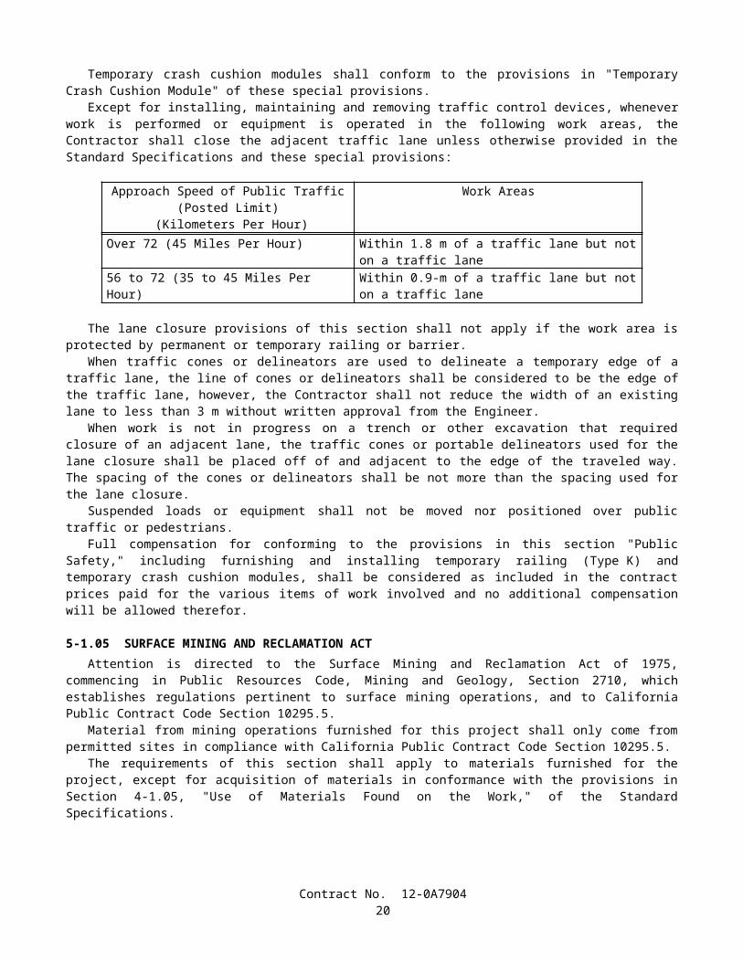
SUBSTITUTION TABLE FOR STRUCTURAL TIMBER AND LUMBER METRIC MINIMUM
DRESSED DRY,SHOWN ON THE PLANS
mm x mm
METRIC MINIMUM DRESSED GREEN,
SHOWN ON THE PLANSmm x mm
NOMINAL SIZE
TO BE SUBSTITUTEDinch x inch
19x89 20x90 1x438x89 40x90 2x464x89 65x90 3x489x89 90x90 4x4
140x140 143x143 6x6140x184 143x190 6x8184x184 190x190 8x8235x235 241x241 10x10286x286 292x292 12x12
SUBSTITUTION TABLE FOR NAILS AND SPIKESMETRIC COMMON NAIL,SHOWN ON THE PLANS
Length, mmDiameter, mm
METRIC BOX NAIL,SHOWN ON THE PLANS
Length, mmDiameter, mm
METRIC SPIKE,SHOWN ON THE
PLANSLength, mm
Diameter, mm
SIZETO BE
SUBSTITUTEDPenny-weight
50.802.87
50.802.51
______ 6d
63.503.33
63.502.87
______ 8d
76.203.76
76.203.25
76.204.88
10d
82.553.76
82.553.25
82.554.88
12d
88.904.11
88.903.43
88.905.26
16d
101.604.88
101.603.76
101.605.72
20d
114.305.26
114.303.76
114.306.20
30d
127.005.72
127.004.11
127.006.68
40d
______ ______ 139.707.19
50d
______ ______ 152.407.19
60d
Contract No. 12-0A790420

SUBSTITUTION TABLE FOR IRRIGATION COMPONENTS
METRICWATER METERS, TRUCK LOADING STANDPIPES, VALVES, BACKFLOW PREVENTERS, FLOW
SENSORS, WYE STRAINERS, FILTER
ASSEMBLY UNITS, PIPE SUPPLY LINES, AND PIPE
IRRIGATION SUPPLY LINES
SHOWN ON THE PLANSDIAMETER NOMINAL
(DN) mm
NOMINAL SIZE
TO BE SUBSTITUTED
inch15 1/220 3/425 132 1-1/440 1-1/250 265 2-1/275 3100 4150 6200 8250 10300 12350 14400 16
Unless otherwise specified, substitutions of United States Standard Measures standard structural shapes corresponding to the metric designations shown on the plans and in conformance with the requirements in ASTM Designation: A 6/A 6M, Annex 2, will be allowed.
8-1.02 PREQUALIFIED AND TESTED SIGNING AND DELINEATION MATERIALSThe Department maintains the following list of Prequalified and Tested Signing and Delineation Materials. The
Engineer shall not be precluded from sampling and testing products on the list of Prequalified and Tested Signing and Delineation Materials.
The manufacturer of products on the list of Prequalified and Tested Signing and Delineation Materials shall furnish the Engineer a Certificate of Compliance in conformance with the provisions in Section 6-1.07, "Certificates of Compliance," of the Standard Specifications for each type of traffic product supplied.
For those categories of materials included in the list of Prequalified and Tested Signing and Delineation Materials, only those products shown within the listing may be used in the work. Other categories of products, not included in the list of Prequalified and Tested Signing and Delineation Materials, may be used in the work provided they conform to the requirements of the Standard Specifications.
Materials and products may be added to the list of Prequalified and Tested Signing and Delineation Materials if the manufacturer submits a New Product Information Form to the New Product Coordinator at the Transportation Laboratory. Upon a Departmental request for samples, sufficient samples shall be submitted to permit performance of required tests. Approval of materials or products will depend upon compliance with the specifications and tests the Department may elect to perform.
Contract No. 12-0A790421
PAVEMENT MARKERS, PERMANENT TYPERetroreflective With Abrasion Resistant Surface (ARS)
A. Apex, Model 921AR (100 mm x 100 mm)B. Ray-O-Lite, Model "AA" ARS (100 mm x 100 mm)C. Stimsonite, Models 911 (100 mm x 100 mm) and 953 (70 mm x 114 mm)D. 3M Series 290 (89 mm x 100 mm)
Retroreflective With Abrasion Resistant Surface (ARS)(Used for recessed applications)
A. Stimsonite, Model 948 (58 mm x 119 mm)B. Ray-O-Lite, Model 2002 (58 mm x 117 mm)C. Stimsonite, Model 944SB (51 mm x 100 mm)D. Ray-O-Lite, Model 2004 ARS (51 mm x 100 mm)*
*For use only in 114 mm wide (older) recessed slots
Non-Reflective For Use With Epoxy Adhesive, 100 mm RoundA. Apex Universal (Ceramic)B. Highway Ceramics, Inc. (Ceramic)
Non-Reflective For Use With Bitumen Adhesive, 100 mm RoundA. Alpine Products, "D-Dot" and "ANR" (ABS)B. Apex Universal (Ceramic)C. Apex Universal, Models 929 (ABS) and 929PP (Polypropylene)D. Elgin Molded Plastics, "Empco-Lite" Model 900 (ABS)E. Highway Ceramics, Inc. (Ceramic)F. Hi-Way Safety, Inc., Models P20-2000W and 2001Y (ABS)G. Interstate Sales, "Diamond Back" (ABS) and (Polypropylene)H. Novabrite Models Adot-w (White) Adot-y (Yellow), (ABS)I. Road Creations, Model RCB4NR (Acrylic)J. Zumar Industries, "Titan TM40A" (ABS)
PAVEMENT MARKERS, TEMPORARY TYPETemporary Markers For Long Term Day/Night Use (6 months or less)
A. Apex Universal, Model 924 (100 mm x 100 mm)B. Elgin Molded Plastics, "Empco-Lite" Model 901 (100 mm x 100 mm)C. Road Creations, Model R41C (100 mm x 100 mm)D. Vega Molded Products "Temporary Road Marker" (75 mm x 100 mm)
Temporary Markers For Short Term Day/Night Use (14 days or less)(For seal coat or chip seal applications, clear protective covers are required)
A. Apex Universal, Model 932B. Bunzl (formerly Davidson Plastics, Models) T.O.M., T.R.P.M., and "HH" (High Heat)C. Hi-Way Safety, Inc., Model 1280/1281
STRIPING AND PAVEMENT MARKING MATERIALPermanent Traffic Striping and Pavement Marking Tape
A. Advanced Traffic Marking, Series 300 and 400B. Brite-Line, Series 1000C. Brite-Line, "DeltaLine XRP"D. Swarco Industries, "Director 35" (For transverse application only)E. Swarco Industries, "Director 60"F. 3M, "Stamark" Series 380 and 5730G. 3M, "Stamark" Series 420 (For transverse application only)
Contract No. 12-0A790422

Temporary (Removable) Striping and Pavement Marking Tape (6 months or less)A. Advanced Traffic Marking, Series 200B. Brite-Line, Series 100C. P.B. Laminations, Aztec, Grade 102D. Swarco Industries, "Director-2" Trelleborg Industri, R140 Series 3M, Series 620 and Series A750 3M, Series A145, Removable Black Line Mask
(Black Tape: for use only on Asphalt Concrete Surfaces)H. Advanced Traffic Marking Black "Hide-A-Line"
(Black Tape: for use only on Asphalt Concrete Surfaces)I. Brite-Line "BTR" Black Removable Tape
(Black Tape: for use only on Asphalt Concrete Surfaces)J. Trelleborg Industri, RB-140
(Black Tape: for use only on Asphalt Concrete Surfaces)
Preformed Thermoplastic (Heated in place)A. Flint Trading, "Premark" and "Premark 20/20 Flex"B. Avery Dennison, "Hotape"
Removable Traffic PaintA. Belpro, Series 250/252 and No. 93 Remover
Ceramic Surfacing Laminate, 150 mm x 150 mmA. Safeline Industries/Highway Ceramics, Inc.
CLASS 1 DELINEATORSOne Piece Driveable Flexible Type, 1700 mm
A. Carsonite, Curve-Flex CFRM-400B. Carsonite, Roadmarker CRM-375C. Bunzl (Formerly Davidson Plastics), "Flexi-Guide Models 400 and 566"D. FlexStake, Model 654 TME. GreenLine Models HWD1-66 and CGD1-66F. J. Miller Industries, Model JMI-375 (with soil anchor)
Special Use Flexible Type, 1700 mmA. Carsonite, "Survivor" (with 450 mm U-Channel base)B. FlexStake, Model 604C. GreenLine Models HWD and CGD (with 450 mm U-Channel base)D. Safe-Hit with 200 mm pavement anchor (SH248-GP1)E. Safe-Hit with 380 mm soil anchor (SH248-GP2) and with 450 mm soil anchor (SH248-GP3)
Surface Mount Flexible Type, 1200 mmA. Bent Manufacturing Company, Masterflex Model MF-180EX-48B. Carsonite, "Super Duck II"C. FlexStake, Surface Mount, Models 704 and 754 TM
CHANNELIZERSSurface Mount Type, 900 mm
A. Bent Manufacturing Company, Masterflex Models MF-360-36 (Round) and MF-180-36 (Flat)B. Carsonite, "Super Duck" (Flat SDF-436, Round SDR-336)C. Carsonite, "Super Duck II" Model SDCF203601MB "The Channelizer"D. Bunzl (Formerly Davidson Plastics), Flex-Guide Models FG300LD and FG300URE. FlexStake, Surface Mount, Models 703 and 753 TMF. GreenLine, Model SMD-36
Contract No. 12-0A790423

G. Hi-Way Safety, Inc. "Channel Guide Channelizer" Model CGC36H. The Line Connection, "Dura-Post" Model DP36-3 (Permanent)I. The Line Connection, "Dura-Post" Model DP36-3C (Temporary)J. Repo, Models 300 and 400K. Safe-Hit, Guide Post, Model SH236SMA
CONICAL DELINEATORS, 1070 mm(For 700 mm Traffic Cones, see Standard Specifications)A. Bent Manufacturing Company "T-Top"B. Plastic Safety Systems "Navigator-42"C. Radiator Specialty Company "Enforcer"D. Roadmaker Company "Stacker"E. TrafFix Devices "Grabber"
OBJECT MARKERSType "K", 450 mm
A. Carsonite, Model SMD 615B. FlexStake, Model 701 KMC. Repo, Models 300 and 400D. Safe-Hit, Model SH718SMAE. The Line Connection, Model DP21-4K
Type "K-4" / "Q" Object Markers, 600 mmA. Bent Manufacturing "Masterflex" Model MF-360-24B. Carsonite, Super Duck IIC. FlexStake, Model 701KMD. Repo, Models 300 and 400E. Safe-Hit, Models SH8 24SMA_WA and SH8 24GP3_WAF. The Line Connection, Model DP21-4Q
TEMPORARY RAILING (TYPE K) REFLECTORS AND CONCRETE BARRIER MARKERS
Impactable TypeA. ARTUK, "FB"B. Bunzl (Formerly Davidson Plastics), Model PCBM-12C. Duraflex Corp., "Flexx 2020" and "Electriflexx"D. Hi-Way Safety, Inc., Model GMKRM100
Non-Impactable TypeA. ARTUK, JD SeriesB. Stimsonite, Model 967 (with 83 mm Acrylic cube corner reflector)C. Stimsonite, Model 967LSD. Vega Molded Products, Models GBM and JD
THRIE BEAM BARRIER MARKERS(For use to the left of traffic)A. Duraflex Corp., "Railrider"B. Bunzl (Formerly Davidson Plastics), "Mini" (75 mm x 254 mm)
CONCRETE BARRIER DELINEATORS, 400 mm(For use to the right of traffic. When mounted on top of barrier, place top of reflective element at 1200 mm)A. Bunzl (Formerly Davidson Plastics), Model PCBM T-16B. Safe-Hit, Model SH216RBMC. Sun-Lab Technology, "Safety Guide Light, Model TM," 130 mm x 130 mm x 80 mm
CONCRETE BARRIER-MOUNTED MINI-DRUM (260 mm x 360 mm x 570 mm)A. Stinson Equipment Company "SaddleMarker"
Contract No. 12-0A790424

SOUND WALL DELINEATOR(Applied vertically. Place top of 75 mm x 300 mm reflective element at 1200 mm above roadway)A. Bunzl (Formerly Davidson Plastics), PCBM S-36B. Sun-Lab Technology, "Safety Guide Light, Model SM12," 130 mm x 130 mm x 80 mm
GUARD RAILING DELINEATOR(Place top of reflective element at 1200 mm above plane of roadway)
Wood Post Type, 686 mmA. Carsonite, Model 427B. Bunzl (Formerly Davidson Plastics), FG 427 and FG 527C. FlexStake, Model 102 GRD. GreenLine GRD 27E. J. Miller Model JMI-375GF. Safe-Hit, Model SH227GRD
Steel Post TypeA. Carsonite, Model CFGR-327 with CFGRBK300 Mounting Bracket
RETROREFLECTIVE SHEETINGChannelizers, Barrier Markers, and Delineators
A. 3M, High IntensityB. Reflexite, PC-1000 Metalized PolycarbonateC. Reflexite, AC-1000 AcrylicD. Reflexite, AP-1000 Metalized PolyesterE. Reflexite, Conformalight, AR-1000 Abrasion Resistant CoatingF. Avery Dennison T-6500 Series (Formerly Stimsonite, Series 6200) (For rigid substrate devices only)G. Nippon Carbide, Flexible Ultralite Grade (ULG) II
Traffic Cones, 330 mm SleevesA. Reflexite SB (Polyester), Vinyl or "TR" (Semi-transparent)
Traffic Cones, 100 mm and 150 mm SleevesA. 3M Series 3840B. Reflexite Vinyl, "TR" (Semi-transparent) or "Conformalight"C. Nippon Carbide, Flexible Ultralite Grade (ULG) II
Barrels and DrumsA. Reflexite, "Conformalight", "Super High Intensity" or "High Impact Drum Sheeting"B. 3M Series 3810C. Nippon Carbide, Flexible Ultralite Grade (ULG) IID. Avery Dennison W-6100
Barricades: Type I, Engineer GradeA. American Decal, AdcoliteB. Avery Dennison, T-1500 and T-1600 seriesC. 3M, Engineer Grade, Series 3170
Barricades: Type II, Super Engineer GradeA. Avery Dennison, T-2500 SeriesB. Kiwalite Type IIC. Nikkalite 1800 Series
Signs: Type II, Super Engineer GradeA. Avery Dennison, T-2500 SeriesB. Kiwalite, Type II
Contract No. 12-0A790425

C. Nikkalite 1800 Series
Signs: Type III, High-Intensity GradeA. 3M Series 3800B. Nippon Carbide, Nikkalite Brand Ultralite Grade II
Signs: Type IV, High-Intensity Prismatic GradeA. Avery Dennison T-6500 (Formerly Stimsonite Series 6200)
Signs: Type VII, High-Intensity Prismatic GradeA. 3M Series 3900
Signs: Type VI, Roll-Up SignsA. Reflexite, Vinyl (Orange)B. Reflexite "SuperBright" (Fluorescent orange)C. Reflexite "Marathon" (Fluorescent orange)D. 3M Series RS34 (Orange) and RS20 (Fluorescent orange)
SPECIALTY SIGN (All Plastic)A. All Sign Products, STOP Sign, 750 mm
SIGN SUBSTRATE FOR CONSTRUCTION AREA SIGNSAluminumFiberglass Reinforced Plastic (FRP)
A. Sequentia, "Polyplate"B. Fiber-Brite
8-1.03 SLAG AGGREGATEAir-cooled iron blast furnace slag shall not be used to produce aggregate for:
A. Structure backfill material.B. Pervious backfill material.C. Permeable material.D. Reinforced or prestressed portland cement concrete component or structure.E. Nonreinforced portland cement concrete component or structure for which a Class 1 Surface Finish is required by
the provisions in Section 51-1.18B, "Class 1 Surface Finish," of the Standard Specifications.
Aggregate produced from slag resulting from a steel-making process shall not be used for a highway construction project except for the following items:
A. Imported Borrow.B. Aggregate Subbase.C. Class 2 Aggregate Base.D. Asphalt Concrete.
Steel slag to be used to produce aggregate for aggregate subbase and Class 2 aggregate base shall be crushed so that 100 percent of the material will pass a 19-mm sieve and then shall be control aged for a period of at least 3 months under conditions that will maintain all portions of the stockpiled material at a moisture content in excess of 6 percent of the dry mass of the aggregate.
A supplier of steel slag aggregate shall provide separate stockpiles for controlled aging of the slag. An individual stockpile shall contain not less than 9075 tonnes nor more than 45 350 tonnes of slag. The material in each individual stockpile shall be assigned a unique lot number and each stockpile shall be identified with a permanent system of signs. The supplier shall maintain a permanent record of the dates on which stockpiles are completed and controlled aging begun, of the dates when controlled aging was completed, and of the dates tests were made and the results of these tests. Moisture tests shall be made at least once each week. No credit for aging will be given for the time period covered by tests which show a
Contract No. 12-0A790426

moisture content of 6 percent or less. The stockpiles and records shall be available to the Engineer during normal working hours for inspection, check testing and review.
The supplier shall notify the Transportation Laboratory, 5900 Folsom Boulevard, Sacramento, California 95819, when each stockpile is completed and controlled aging begun. No more aggregate shall be added to the stockpile unless a new aging period is initiated. A further notification shall be sent when controlled aging is completed.
The supplier shall provide a Certificate of Compliance in conformance with the provisions in Section 6-1.07, "Certificates of Compliance," of the Standard Specifications. Each stockpile or portion of a stockpile that is used in the work will be considered a lot. The Certificates of Compliance shall state that the steel slag aggregate has been aged in a stockpile for at least 3 months at a moisture content in excess of 6 percent of the dry mass of the aggregate.
Steel slag used for imported borrow shall be weathered for at least 3 months. Prior to the use of steel slag as imported borrow, the supplier shall furnish a Certificate of Compliance in conformance with the provisions in Section 6 -1.07, "Certificates of Compliance," of the Standard Specifications. The Certificate of Compliance shall state that the steel slag has been weathered for at least 3 months.
Each delivery of aggregate containing steel slag for use as aggregate subbase or Class 2 aggregate base shall be accompanied by a delivery tag for each load which will identify the lot of material by stockpile number, where the slag was aged, and the date that the stockpile was completed and controlled aging begun.
Air-cooled iron blast furnace slag or natural aggregate may be blended in proper combinations with steel slag aggregate to produce the specified gradings, for those items for which steel slag aggregate is permitted, unless otherwise provided.
Aggregate containing slag shall meet the applicable quality requirements for the items in which the aggregate is used.The combined slag aggregate shall conform to the specified grading for the item in which it is used. The grading will be
determined by California Test 202, modified by California Test 105 when there is a difference in specific gravity of 0.2 or more between the coarse and fine portion of the aggregate or between blends of different aggregates.
No aggregate produced from slag shall be placed within 0.3-m, measured in any direction, of a non-cathodically protected pipe or structure unless the aggregate is incorporated in portland cement concrete pavement, in asphalt concrete, or in treated base.
When slag is used as aggregate in asphalt concrete, the Kc factor requirements, as determined by California Test 303, will not apply.
Slag aggregate used for embankment construction shall not be placed within 0.46-m of finished slope lines, measured normal to the plane of the slope.
If steel slag aggregates are used to make asphalt concrete, there shall be no other aggregates used in the mixture, except that up to 50 percent of the material passing the 4.75-mm sieve may consist of iron blast furnace slag aggregates or natural aggregates, or a combination thereof. If iron blast furnace aggregates or natural aggregates or a combination thereof are used in the mix, each type of aggregate shall be fed to the drier at a uniform rate. The rate of feed of each type of aggregate shall be maintained within 10 percent of the amount set. Adequate means shall be provided for controlling and checking the accuracy of the feeder.
In addition to the requirements of Section 39-3.01, "Storage," of the Standard Specifications, steel slag aggregate shall be stored separately from iron blast furnace slag aggregate and each type of slag aggregate shall also be stored separately from natural aggregate.
Asphalt concrete produced from more than one of the following shall not be placed in the same layer: steel slag aggregates, iron blast furnace slag aggregates, natural aggregates or any combination thereof. Once a type of aggregate or aggregates is selected, it shall not be changed without prior approval by the Engineer.
If steel slag aggregates are used to produce asphalt concrete, and if the specific gravity of a compacted stabilometer test specimen is in excess of 2.40, the quantity of asphalt concrete to be paid for will be reduced. The stabilometer test specimen will be fabricated in conformance with the procedures in California Test 304 and the specific gravity of the specimen will be determined in conformance with Method C of California Test 308. The pay quantity of asphalt concrete will be determined by multiplying the quantity of asphalt concrete placed in the work by 2.40 and dividing the result by the specific gravity of the compacted stabilometer test specimen. Such reduction in quantity will be determined and applied as often as is necessary to ensure accurate results as determined by the Engineer.
Contract No. 12-0A790427
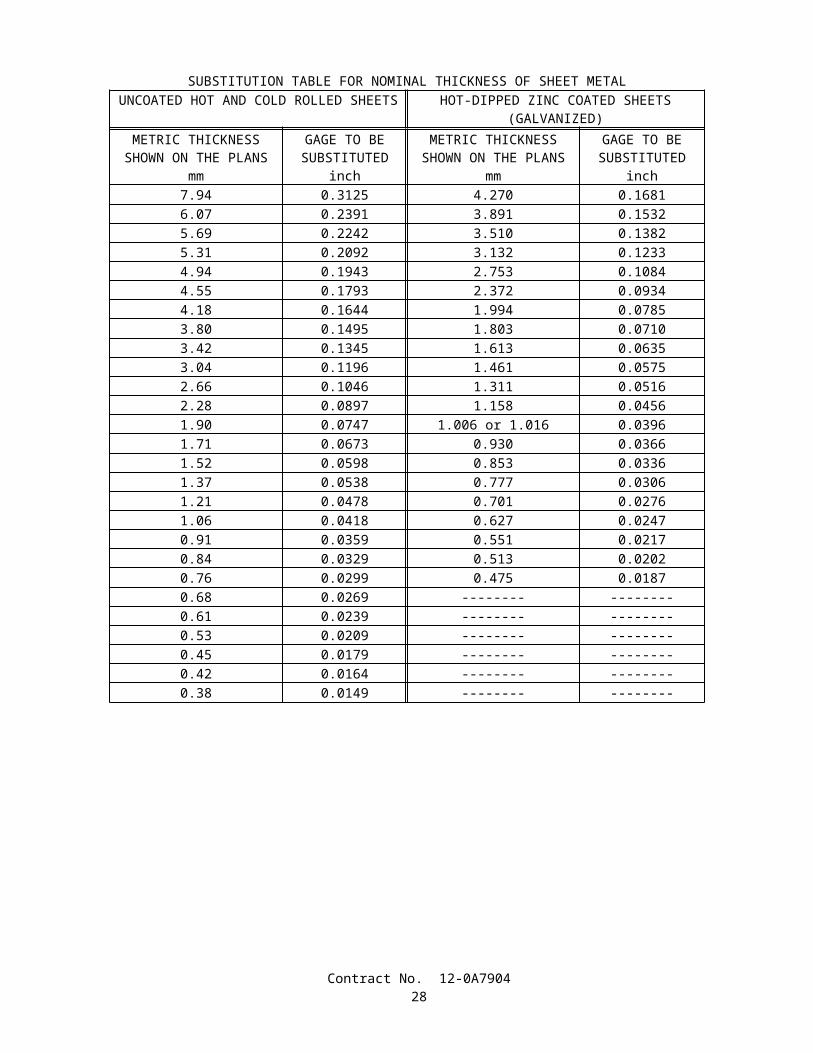
8-1.04 MISCELLANEOUS METALThe table in the tenth paragraph of Section 75-1.02, "Miscellaneous Iron and Steel," of the Standard Specifications is
amended to read:
Material SpecificationSteel bars, plates and shapes
ASTM Designation: A 36/A 36M or A 575, A 576 (AISI or M Grades 1016 through 1030 except Grade 1017)
Steel fastener components for general applications:Bolts and studs ASTM Designation: A 307Headed anchor bolts ASTM Designation: A 307, Grade B, including
S1 supplementary requirementsNonheaded anchor bolts
ASTM Designation: A 307, Grade C, including S1 supplementary requirements and S1.6 of AASHTO Designation: M 314 supplementary requirementsor AASHTO Designation: M 314, Grade 36 or 55, including S1 supplementary requirements
High-strength bolts and studs, threaded rods, and nonheaded anchor bolts
ASTM Designation: A 449, Type 1
Nuts ASTM Designation: A 563, including Appendix X1*
Washers ASTM Designation: F 844Components of high-strength steel fastener assemblies for use in structural steel joints:
Bolts ASTM Designation: A 325, Type 1Tension control bolts ASTM Designation: F 1852, Type 1Nuts ASTM Designation: A 563, including
Appendix X1*Hardened washers ASTM Designation: F 436, Type 1, Circular,
including S1 supplementary requirementsDirect tension indicators
ASTM Designation: F 959, Type 325, zinc-coated
Stainless steel fasteners (Alloys 304 & 316) for general applications:Bolts, screws, studs, threaded rods, and nonheaded anchor bolts
ASTM Designation: F 593 or F 738M
Nuts ASTM Designation: F 594 or F 836MWashers ASTM Designation: A 240/A 240M and
ANSI B 18.22MCarbon-steel castings ASTM Designation: A 27/A 27M, Grade 65-35
[450-240], Class 1Malleable iron castings ASTM Designation: A 47, Grade 32510 or
A 47M, Grade 22010Gray iron castings ASTM Designation: A 48, Class 30BDuctile iron castings ASTM Designation: A 536, Grade 65-45-12Cast iron pipe Commercial qualitySteel pipe Commercial quality, welded or extrudedOther parts for general applications
Commercial quality
* Zinc-coated nuts that will be tightened beyond snug or wrench tight shall be furnished with a dyed dry lubricant conforming to Supplementary Requirement S2 in ASTM Designation: A 563.
Contract No. 12-0A790428
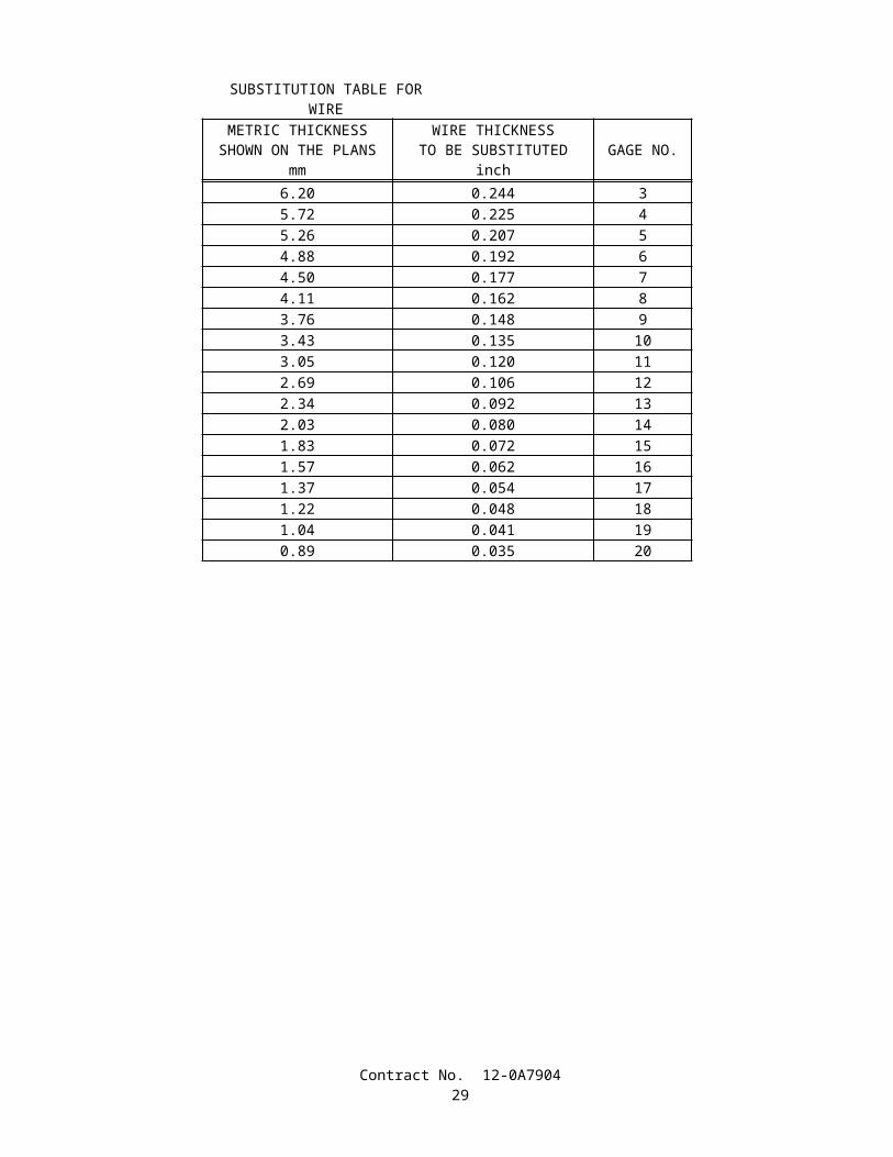
The table in the eighteenth paragraph of Section 75-1.03, "Miscellaneous Bridge Metal," of the Standard Specifications is amended to read:
Stud Diameter(millimeters)
Sustained TensionTest Load
(kilonewtons)29.01-33.00 137.923.01-29.00 79.621.01-23.00 64.1
* 18.01-21.00 22.215.01-18.00 18.212.01-15.00 14.29.01-12.00 9.346.00-9.00 4.23
* Maximum stud diameter permitted for mechanical expansion anchors.
The table in the nineteenth paragraph of Section 75-1.03, "Miscellaneous Bridge Metal," of the Standard Specifications is amended to read:
Stud Diameter(millimeters)
UltimateTensile Load(kilonewtons)
30.01-33.00 112.127.01-30.00 88.123.01-27.00 71.220.01-23.00 51.616.01-20.00 32.014.01-16.00 29.412.00-14.00 18.7
The table in the twenty-second paragraph of Section 75-1.03, "Miscellaneous Bridge Metal," of the Standard Specifications is amended to read:
Installation Torque Values, (newton meters)
Stud Diameter(millimeters)
Shell TypeMechanicalExpansionAnchors
Integral Stud TypeMechanicalExpansionAnchors
Resin Capsule Anchors
andCast-in-Place Inserts
29.01-33.00 — — 54023.01-29.00 — — 31521.01-23.00 — — 23518.01-21.00 110 235 20015.01-18.00 45 120 10012.01-15.00 30 65 40 9.01-12.00 15 35 246.00-9.00 5 10 —
SECTION 8-2. CONCRETE
8-2.01 PORTLAND CEMENT CONCRETEPortland cement concrete shall conform to the provisions in Section 90, "Portland Cement Concrete," of the Standard
Specifications and these special provisions.References to Section 90-2.01, "Portland Cement," of the Standard Specifications shall mean Section 90-2.01, "Cement,"
of the Standard Specifications.
Contract No. 12-0A790429

Mineral admixture shall be combined with cement in conformance with the provisions in Section 90-4.08, "Required Use of Mineral Admixtures," of the Standard Specifications for the concrete materials specified in Section 56-2, "Roadside Signs," of the Standard Specifications.
The requirements of Section 90-4.08, "Required Use of Mineral Admixture," of the Standard Specifications shall not apply to Section 19-3.025C, "Soil Cement Bedding," of the Standard Specifications.
The Department maintains a list of sources of fine and coarse aggregate that have been approved for use with a reduced amount of mineral admixture in the total amount of cementitious material to be used. A source of aggregate will be considered for addition to the approved list if the producer of the aggregate submits to the Transportation Laboratory certified test results from a qualified testing laboratory that verify the aggregate complies with the requirements. Prior to starting the testing, the aggregate test shall be registered with the Department. A registration number can be obtained by calling (916) 227-7228. The registration number shall be used as the identification for the aggregate sample in correspondence with the Department. Upon request, a split of the tested sample shall be provided to the Department. Approval of aggregate will depend upon compliance with the specifications, based on the certified test results submitted, together with any replicate testing the Department may elect to perform. Approval will expire 3 years from the date the most recent registered and evaluated sample was collected from the aggregate source.
Qualified testing laboratories shall conform to the following requirements:
A. Laboratories performing ASTM Designation: C 1293 shall participate in the Cement and Concrete Reference Laboratory (CCRL) Concrete Proficiency Sample Program and shall have received a score of 3 or better on all tests of the previous 2 sets of concrete samples.
B. Laboratories performing ASTM Designation: C 1260 shall participate in the Cement and Concrete Reference Laboratory (CCRL) Pozzolan Proficiency Sample Program and shall have received a score of 3 or better on the shrinkage and soundness tests of the previous 2 sets of pozzolan samples.
Aggregates on the list shall conform to one of the following requirements:
A. When the aggregate is tested in conformance with the requirements in California Test 554 and ASTM Designation: C 1293, the average expansion at one year shall be less than or equal to 0.040 percent; or
B. When the aggregate is tested in conformance with the requirements in California Test 554 and ASTM Designation: C 1260, the average of the expansion at 16 days shall be less than or equal to 0.15 percent.
The amounts of cement and mineral admixture used in cementitious material shall be sufficient to satisfy the minimum cementitious material content requirements specified in Section 90-1.01, "Description," or Section 90-4.05, "Optional Use of Chemical Admixtures," of the Standard Specifications and shall conform to the following:
A. The minimum amount of cement shall not be less than 75 percent by mass of the specified minimum cementitious material content.
B. The minimum amount of mineral admixture to be combined with cement shall be determined using one of the following criteria:
1. When the calcium oxide content of a mineral admixture is equal to or less than 2 percent by mass, the amount of mineral admixture shall not be less than 15 percent by mass of the total amount of cementitious material to be used in the mix.
2. When the calcium oxide content of a mineral admixture is greater than 2 percent by mass, and any of the aggregates used are not listed on the approved list as specified in these special provisions, then the amount of mineral admixture shall not be less than 25 percent by mass of the total amount of cementitious material to be used in the mix.
3. When the calcium oxide content of a mineral admixture is greater than 2 percent by mass and the fine and coarse aggregates are listed on the approved list as specified in these special provisions, then the amount of mineral admixture shall not be less than 15 percent by mass of the total amount of cementitious material to be used in the mix.
4. When a mineral admixture that conforms to the provisions for silica fume in Section 90-2.04, "Admixture Materials," of the Standard Specifications is used, the amount of mineral admixture shall not be less than 10 percent by mass of the total amount of cementitious material to be used in the mix.
5. When a mineral admixture that conforms to the provisions for silica fume in Section 90-2.04, "Admixture Materials," of the Standard Specifications is used and the fine and coarse aggregates are listed on the approved list as specified in these special provisions, then the amount of mineral admixture shall not be less than 7 percent by mass of the total amount of cementitious material to be used in the mix.
Contract No. 12-0A790430

C. The total amount of mineral admixture shall not exceed 35 percent by mass of the total amount of cementitious material to be used in the mix. Where Section 90-1.01, "Description," of the Standard Specifications specifies a maximum cementitious content in kilograms per cubic meter, the total mass of cement and mineral admixture per cubic meter shall not exceed the specified maximum cementitious material content.
Unless otherwise specified, mineral admixture will not be required in portland cement concrete used for precast concrete girders.
SECTION 8-3. (BLANK)
SECTION 9. (BLANK)
SECTION 10. CONSTRUCTION DETAILS
SECTION 10-1. GENERAL
10-1.01 WATER POLLUTION CONTROLWater pollution control work shall conform to the provisions in Section 7-1.01G, "Water Pollution," of the Standard
Specifications and these special provisions.This project shall conform to the requirements of the State of California Department of Transportation (Caltrans)
Statewide NPDES Storm Water Permit No. CAS000003 issued by the State Water Resources Control Board. This permit, hereafter referred to as "Statewide Permit", regulates storm water and non-storm water discharges associated with Caltrans construction activities.
Water pollution control work shall conform to the requirements in the "Storm Water Pollution Prevention Plan (SWPPP) and Water Pollution Control Program (WPCP) Preparation Manual" and the "Construction Site Best Management Practices (BMPs) Manual," and addenda thereto issued up to, and including, the date of advertisement of the project, hereafter referred to respectively as the "Preparation Manual" and the "Construction Site BMP Manual" and collectively as the "Manuals." Copies of the Statewide Permit and the Manuals may be obtained from the Department of Transportation, Material Operations Branch, Publication Distribution Unit, 1900 Royal Oaks Drive, Sacramento, California 95815, Telephone: (916) 445-3520. Copies of the Manuals may also be obtained from the Department's Internet Web Site at: http://www.dot.ca.gov/hq/construc/stormwater.html.
Copies of the Manuals are available for review at District 12, Construction Administration Branch, 3351 Michelson Drive, 3rd Floor, Irvine, California 92612, Telephone: (949) 724-2188.
The Contractor shall know and fully comply with the applicable provisions of the Manuals and Federal, State, and local regulations that govern the Contractor's operations and storm water discharges from both the project site and areas of disturbance outside the project limits during construction.
Unless arrangements for disturbance of areas outside the project limits are made by the Department and made part of the contract, it is expressly agreed that the Department assumes no responsibility whatsoever to the Contractor or property owner with respect to any arrangements made between the Contractor and property owner to allow disturbance of areas outside the project limits.
The Contractor shall be responsible for the costs and for liabilities imposed by law as a result of the Contractor's failure to comply with the requirements set forth in this section "Water Pollution Control" including, but not limited to, compliance with the applicable provisions of the Manuals and Federal, State, and local regulations. For the purposes of this paragraph, costs and liabilities include, but are not limited to, fines, penalties, and damages whether assessed against the State or the Contractor, including those levied under the Federal Clean Water Act and the State Porter Cologne Water Quality Act.
In addition to the remedies authorized by law, an amount of the money due the Contractor under the contract, as determined by the Department, may be retained by the State of California until disposition has been made of the costs and liabilities.
The retention of money due the Contractor shall be subject to the following:
A. The Department will give the Contractor 30 days notice of the Department's intention to retain funds from partial payments which may become due to the Contractor prior to acceptance of the contract. Retention of funds from payments made after acceptance of the contract may be made without prior notice to the Contractor.
B. No retention of additional amounts out of partial payments will be made if the amount to be retained does not exceed the amount being withheld from partial payments pursuant to Section 9-1.06, "Partial Payments," of the Standard Specifications.
Contract No. 12-0A790431

C. If the Department has retained funds and it is subsequently determined that the State is not subject to the costs and liabilities in connection with the matter for which the retention was made, the Department shall be liable for interest on the amount retained at the legal rate of interest for the period of the retention.
Conformance with the provisions in this section "Water Pollution Control" shall not relieve the Contractor from the Contractor's responsibilities as provided in Section 7, "Legal Relations and Responsibilities," of the Standard Specifications.
WATER POLLUTION CONTROL PROGRAM PREPARATION, APPROVAL AND UPDATESAs part of the water pollution control work, a Water Pollution Control Program, hereafter referred to as the "WPCP," is
required for this contract. The WPCP shall conform to the provisions in Section 7-1.01G, "Water Pollution," of the Standard Specifications, the requirements in the Manuals, and these special provisions.
No work having potential to cause water pollution, as determined by the Engineer, shall be performed until the WPCP has been approved by the Engineer.
Within 30 days after the approval of the contract, the Contractor shall submit 3 copies of the WPCP to the Engineer. The Engineer will have 7 days to review the WPCP. If revisions are required, as determined by the Engineer, the Contractor shall revise and resubmit the WPCP within 7 days of receipt of the Engineer's comments. The Engineer will have 7 days to review the revisions. Upon the Engineer's approval of the WPCP, 3 additional copies of the WPCP incorporating the required changes shall be submitted to the Engineer. Minor changes or clarifications to the initial submittal may be made and attached as amendments to the WPCP. In order to allow construction activities to proceed, the Engineer may conditionally approve the WPCP while minor revisions or amendments are being completed.
The WPCP shall identify pollution sources that may adversely affect the quality of storm water discharges associated with the project and shall identify water pollution control measures, hereafter referred to as control measures, to be constructed, implemented, and maintained in order to reduce to the extent feasible pollutants in storm water discharges from the construction site during construction under this contract.
The WPCP shall incorporate control measures in the following categories:
A. Soil stabilization;B. Sediment control;C. Tracking control;D. Wind erosion control;E. Non-storm water control; andF. Waste management and material pollution control.
Specific objectives and minimum requirements for each category of control measures are contained in the Manuals.The Contractor shall consider the objectives and minimum requirements presented in the Manuals for each of the above
categories. When minimum requirements are listed for any category, the Contractor shall incorporate into the WPCP and implement on the project, one or more of the listed minimum controls required in order to meet the pollution control objectives for the category. In addition, the Contractor shall consider other control measures presented in the Manuals and shall incorporate into the WPCP and implement on the project the control measures necessary to meet the objectives of the WPCP. The Contractor shall document the selection process in conformance with the procedure specified in the Manuals.
The WPCP shall include, but not be limited to, the following items as described in the Preparation Manual:
A. Project description and Contractor's certification;B. Project information;C. Pollution sources, control measures, and water pollution control drawings; andD. Amendments, if any.
The Contractor shall amend the WPCP, graphically and in narrative form, whenever there is a change in construction activities or operations which may affect the discharge of significant quantities of pollutants to surface waters, ground waters, municipal storm drain systems or when deemed necessary by the Engineer. The WPCP shall be amended if the WPCP has not achieved the objective of reducing pollutants in storm water discharges. Amendments shall show additional control measures or revised operations, including those in areas not shown in the initially approved WPCP, which are required on the project to control water pollution effectively. Amendments to the WPCP shall be submitted for review and approval by the Engineer in the same manner specified for the initially approved WPCP. Amendments shall be dated and attached to the on-site WPCP document.
The Contractor shall keep a copy of the WPCP, together with updates, revisions and amendments at the project site.
Contract No. 12-0A790432

WPCP IMPLEMENTATIONUpon approval of the WPCP, the Contractor shall be responsible throughout the duration of the project for installing,
constructing, inspecting, and maintaining the control measures included in the WPCP and any amendments thereto and for removing and disposing of temporary control measures. Unless otherwise directed by the Engineer or specified in these special provisions, the Contractor's responsibility for WPCP implementation shall continue throughout any temporary suspension of work ordered in conformance with the provisions in Section 8-1.05, "Temporary Suspension of Work," of the Standard Specifications. Requirements for installation, construction, inspection, maintenance, removal, and disposal of control measures are specified in the Manuals and these special provisions.
Soil stabilization practices and sediment control measures, including minimum requirements, shall be provided year round.
Implementation of soil stabilization practices and sediment control measures for soil-disturbed areas on the project site shall be completed, except as provided for below, not later than 20 days prior to the beginning of the rainy season defined as between October 1 and April 30 or upon start of applicable construction activities for projects which begin either during or within 20 days of the rainy season.
Throughout the rainy season, the active, soil-disturbed area of the project site shall be not more than 1.9 hectares. The Engineer may approve, on a case-by-case basis, expansions of the active, soil-disturbed area limit. The Contractor shall demonstrate the ability and preparedness to fully deploy soil stabilization practices and sediment control measures to protect soil-disturbed areas on the project site before the onset of precipitation. A quantity of soil stabilization and sediment control materials shall be maintained on site equal to 100 percent of that sufficient to protect unprotected, soil-disturbed areas on the project site. A detailed plan for the mobilization of sufficient labor and equipment shall be maintained to fully deploy control measures required to protect unprotected, soil-disturbed areas on the project site prior to the onset of precipitation. A current inventory of control measure materials and the detailed mobilization plan shall be included as part of the WPCP.
Throughout the rainy season, soil-disturbed areas on the project site shall be considered to be nonactive whenever soil disturbing activities are expected to be discontinued for a period of 20 or more days and the areas are fully protected. Areas that will become nonactive either during the rainy season or within 20 days thereof shall be fully protected with soil stabilization practices and sediment control measures within 10 days of the discontinuance of soil disturbing activities or prior to the onset of precipitation, whichever is first to occur.
Throughout the rainy season, active soil-disturbed areas of the project site shall be fully protected at the end of each day with soil stabilization practices and sediment control measures unless fair weather is predicted through the following work day. The weather forecast shall be monitored by the Contractor on a daily basis. The National Weather Service forecast shall be used. An alternative weather forecast proposed by the Contractor may be used if approved by the Engineer. If precipitation is predicted prior to the end of the following work day, construction scheduling shall be modified, as required, and functioning control measures shall be deployed prior to the onset of the precipitation.
The Contractor shall implement, year-round and throughout the duration of the project, control measures included in the WPCP for tracking control, wind erosion control, non-storm water control, and waste management and material pollution control.
The Engineer may order the suspension of construction operations which create water pollution if the Contractor fails to conform to the provisions in this section "Water Pollution Control" as determined by the Engineer.
MAINTENANCETo ensure the proper implementation and functioning of control measures, the Contractor shall regularly inspect and
maintain the construction site for the control measures identified in the WPCP. The Contractor shall identify corrective actions and time needed to address any deficient measures or reinitiate any measures that have been discontinued.
The construction site inspection checklist provided in the Preparation Manual shall be used to ensure that the necessary measures are being properly implemented, and to ensure that the control measures are functioning adequately. One copy of each site inspection record shall be submitted to the Engineer.
During the rainy season, inspections of the construction site shall be conducted by the Contractor to identify deficient measures, as follows:
A. Prior to a forecast storm;B. After all precipitation which causes runoff capable of carrying sediment from the construction site;C. At 24-hour intervals during extended precipitation events; andD. Routinely, at a minimum of once every 2 weeks.
If the Contractor or the Engineer identifies a deficiency in the deployment or functioning of an identified control measure, the deficiency shall be corrected immediately. The deficiency may be corrected at a later date and time if requested by the Contractor and approved by the Engineer in writing, but not later than the onset of subsequent precipitation events. The correction of deficiencies shall be at no additional cost to the State.
Contract No. 12-0A790433

PAYMENTFull compensation for conforming to the provisions in this section shall be considered as included in the prices paid for
the various contract items of work involved and no additional compensation will be allowed therefor.Those control measures for which there is a contract item of work will be measured and paid for as that contract item of
work.The Engineer will retain an amount equal to 25 percent of the estimated value of the contract work performed during
estimate periods in which the Contractor fails to conform to the provisions in this section "Water Pollution Control" as determined by the Engineer.
Retentions for failure to conform to the provisions in this section "Water Pollution Control" shall be in addition to the other retentions provided for in the contract. The amounts retained for failure of the Contractor to conform to the provisions in this section will be released for payment on the next monthly estimate for partial payment following the date that a WPCP has been implemented and maintained and water pollution is adequately controlled, as determined by the Engineer.
10-1.02 PROGRESS SCHEDULEProgress schedules are required for this contract and shall be submitted in conformance with the provisions in
Section 8-1.04, "Progress Schedule," of the Standard Specifications and these special provisions, unless otherwise authorized in writing by the Engineer.
The second paragraph of Section 8-1.04, "Progress Schedule," of the Standard Specifications shall not apply.
10-1.03 OBSTRUCTIONSAttention is directed to Section 8-1.10, "Utility and Non-Highway Facilities," and Section 15, "Existing Highway
Facilities," of the Standard Specifications and these special provisions.Attention is directed to the existence of certain underground facilities that may require special precautions be taken by
the Contractor to protect the health, safety and welfare of workers and of the public. Facilities requiring special precautions include, but are not limited to: conductors of petroleum products, oxygen, chlorine, and toxic or flammable gases; natural gas in pipelines greater than 150 mm in diameter or pipelines operating at pressures greater than 415 kPa (gage); underground electric supply system conductors or cables, with potential to ground of more than 300 V, either directly buried or in a duct or conduit which do not have concentric grounded or other effectively grounded metal shields or sheaths.
If these facilities are not located on the plans in both alignment and elevation, no work shall be performed in the vicinity of the facilities, except as provided herein for conduit to be placed under pavement, until the owner, or the owner's representative, has located the facility by potholing, probing or other means that will locate and identify the facility. Conduit to be installed under pavement in the vicinity of these facilities shall be placed by the trenching method in conformance with the provisions in "Conduit" of these special provisions. If, in the opinion of the Engineer, the Contractor's operations are delayed or interfered with by reason of the utility facilities not being located by the owner or the owner's representative, the State will compensate the Contractor for the delays to the extent provided in Section 8-1.09, "Right of Way Delays," of the Standard Specifications, and not otherwise, except as provided in Section 8-1.10, "Utility and Non-Highway Facilities," of the Standard Specifications.
The Contractor shall notify the Engineer and the appropriate regional notification center for operators of subsurface installations at least 2 working days, but not more than 14 calendar days, prior to performing any excavation or other work close to any underground pipeline, conduit, duct, wire or other structure. Regional notification centers include, but are not limited to, the following:
Notification Center Telephone NumberUnderground Service Alert-Northern California (USA) 1-800-642-2444
1-800-227-2600Underground Service Alert-Southern California (USA) 1-800-422-4133
1-800-227-2600
10-1.04 MOBILIZATIONMobilization shall conform to the provisions in Section 11, "Mobilization," of the Standard Specifications.
10-1.05 CONSTRUCTION AREA TRAFFIC CONTROL DEVICES Flagging, signs, and all other traffic control devices furnished, installed, maintained, and removed when no longer
required shall conform to the provisions in Section 12, "Construction Area Traffic Control Devices," of the Standard Specifications and these special provisions.
Contract No. 12-0A790434

Category 1 traffic control devices are defined as those devices that are small and lightweight (less than 45 kg), and have been in common use for many years. The devices shall be known to be crashworthy by crash testing, crash testing of similar devices, or years of demonstrable safe performance. Category 1 traffic control devices include traffic cones, plastic drums, portable delineators, and channelizers.
If requested by the Engineer, the Contractor shall provide written self-certification for crashworthiness of Category 1 traffic control devices. Self-certification shall be provided by the manufacturer or Contractor and shall include the following: date, Federal Aid number (if applicable), expenditure authorization, district, county, route and kilometer post of project limits; company name of certifying vendor, street address, city, state and zip code; printed name, signature and title of certifying person; and an indication of which Category 1 traffic control devices will be used on the project. The Contractor may obtain a standard form for self-certification from the Engineer.
Category 2 traffic control devices are defined as those items that are small and lightweight (less than 45 kg), that are not expected to produce significant vehicular velocity change, but may otherwise be potentially hazardous. Category 2 traffic control devices include: barricades and portable sign supports.
Category 2 devices purchased on or after October 1, 2000 shall be on the Federal Highway Administration (FHWA) Acceptable Crashworthy Category 2 Hardware for Work Zones list. This list is maintained by FHWA and can be located at the following internet address: http://safety.fhwa.dot.gov/fourthlevel/hardware/listing.cfm?code=workzone. The Department maintains a secondary list at the following internet address: http://www.dot.ca.gov/hq/traffops/signtech/signdel/pdffiles.htm.
Category 2 devices that have not received FHWA acceptance, and were purchased before October 1, 2000, may continue to be used until they complete their useful service life or until January 1, 2003, whichever comes first. Category 2 devices in use that have received FHWA acceptance shall be labeled with the FHWA acceptance letter number and the name of the manufacturer by the start of the project. The label shall be readable. After January 1, 2003, all Category 2 devices without a label shall not be used on the project.
Full compensation for providing self-certification for crashworthiness of Category 1 traffic control devices and labeling Category 2 devices as specified shall be considered as included in the prices paid for the various contract items of work requiring the use of the Category 1 or Category 2 traffic control devices and no additional compensation will be allowed therefor.
10-1.06 CONSTRUCTION AREA SIGNSConstruction area signs shall be furnished, installed, maintained, and removed when no longer required in conformance
with the provisions in Section 12, "Construction Area Traffic Control Devices," of the Standard Specifications and these special provisions.
Attention is directed to the provisions in "Prequalified and Tested Signing and Delineation Materials" of these special provisions. Type II retroreflective sheeting shall not be used on construction area sign panels.
The Contractor shall notify the appropriate regional notification center for operators of subsurface installations at least 2 working days, but not more than 14 calendar days, prior to commencing excavation for construction area sign posts. The regional notification centers include, but are not limited to, the following:
Notification Center Telephone NumberUnderground Service Alert-Northern California (USA) 1-800-642-2444
1-800-227-2600Underground Service Alert-Southern California (USA) 1-800-422-4133
1-800-227-2600
Excavations required to install construction area signs shall be performed by hand methods without the use of power equipment, except that power equipment may be used if it is determined there are no utility facilities in the area of the proposed post holes.
Sign substrates for stationary mounted construction area signs may be fabricated from fiberglass reinforced plastic as specified under "Prequalified and Tested Signing and Delineation Materials" of these special provisions.
10-1.07 MAINTAINING TRAFFICAttention is directed to Sections 7-1.08, "Public Convenience," 7-1.09, "Public Safety," and 12, "Construction Area
Traffic Control Devices," of the Standard Specifications and to the provisions in "Public Safety" of these special provisions and these special provisions. Nothing in these special provisions shall be construed as relieving the Contractor from the responsibilities specified in Section 7-1.09.
Lane closures shall conform to the provisions in section "Traffic Control System for Lane Closure" of these special provisions.
Contract No. 12-0A790435

In addition to the provisions set forth in "Public Safety" of these special provisions, whenever work to be performed on the freeway traveled way (except the work of installing, maintaining and removing traffic control devices) is within 1.8 m of the adjacent traffic lane, the adjacent traffic lane shall be closed.
Personal vehicles of the Contractor's employees shall not be parked within the freeway right of way. The Contractor shall notify local authorities of the Contractor's intent to begin work at least 5 days before work is begun.
The Contractor shall cooperate with local authorities relative to handling traffic through the area and shall make arrangements relative to keeping the working area clear of parked vehicles.
Whenever vehicles or equipment are parked on the shoulder within 1.8 m of a traffic lane, the shoulder area shall be closed as shown on the plans.
Lanes shall be closed only during the hours shown on the charts included in this section "Maintaining Traffic." Except work required under Sections 7-1.08 and 7-1.09, work that interferes with public traffic shall be performed only during the hours shown for lane closures.
Designated legal holidays are: January 1st, the third Monday in February, the last Monday in May, July 4th, the first Monday in September, November 11th, Thanksgiving Day, the day after Thanksgiving Day and December 25th. When a designated legal holiday falls on a Sunday, the following Monday shall be a designated legal holiday. When November 11th falls on a Saturday, the preceding Friday shall be a designated legal holiday.
Minor deviations from the requirements of this section concerning hours of work which do not significantly change the cost of the work may be permitted upon the written request of the Contractor, if in the opinion of the Engineer, public traffic will be better served and the work expedited. These deviations shall not be adopted by the Contractor until the Engineer has approved the deviations in writing. All other modifications will be made by contract change order.
Chart No. 1 Multilane Lane Requirements
Location: NB & SB 5 from Routes 5/55 interchange to Routes 5/22/57 interchange
a.m. p.m.FROM HOUR TO HOUR 12 1 2 3 4 5 6 7 8 9 10 11 12 1 2 3 4 5 6 7 8 9 10 11 12Mondays through Thursdays 3 3 3 3 3 S S S S S S S S S 3
Fridays 3 3 3 3 3 S S S S S S S S SSaturdays 3 3 3 3 3 3 S S SSundays 3 3 3 3 3 3 3 S S S 3
Day before designated legal holiday 3 3 3 3 3 S S S S S S S S SDesignated legal holidays
Legend:3 Three adjacent lanes open in direction of travel
S Shoulder may be closed
No lane closure allowed
REMARKS: Open lane(s) are mainline lanes not HOV or merging lane(s). No closure sign(s) shall be exposed to public traffic more than 30 minutes before or after a closure except as
otherwise indicated in these special provisions. Shoulders may be closed when adjacent lane is closed. On – Off ramps shall be closed when the adjacent mainline lane is closed.
Contract No. 12-0A790436

Chart No. 2 Multilane Lane Requirements
Location: NB & SB 5 HOV lane between Main street under-crossing and 4th street.
a.m. p.m.FROM HOUR TO HOUR 12 1 2 3 4 5 6 7 8 9 10 11 12 1 2 3 4 5 6 7 8 9 10 11 12Mondays through Thursdays H H H H H H H
Fridays H H H H H HSaturdays H H H H H H HSundays H H H H H H H H H
Day before designated legal holiday H H H H H HDesignated legal holidays
Legend:H HOV lane may be closed
No lane closure allowed
REMARKS: No closure sign(s) shall be exposed to public traffic more than 30 minutes before or after a closure except as
otherwise indicated in these special provisions.
Chart No. 3 Multilane Lane Requirements
Location: NB55 at Rte 5
a.m. p.m.FROM HOUR TO HOUR 12 1 2 3 4 5 6 7 8 9 10 11 12 1 2 3 4 5 6 7 8 9 10 11 12Mondays through Thursdays 2 2 2 2 2 S S S S S S S S S 2
Fridays 2 2 2 2 2 S S S S S S S S SSaturdays 2 2 2 2 2 2 S S SSundays 2 2 2 2 2 2 2 S S S 2
Day before designated legal holiday 2 2 2 2 2 S S S S S S S S SDesignated legal holidays
Legend:2 Two adjacent lanes open in direction of travel
S Shoulder may be closed
No lane closure allowed
REMARKS: Open lane(s) are mainline lanes not HOV or auxiliary lane(s). No closure sign(s) shall be exposed to public traffic more than 30 minutes before or after a closure except as
otherwise indicated in these special provisions. Shoulders may be closed when adjacent lane is closed. On – Off ramps shall be closed when the adjacent mainline lane is closed.
Contract No. 12-0A790437
Chart No. 1 Ramp And Connector Lane Requirements
Location: All Rte 5 on and off ramps between 5/55 interchange and 5/22/57 interchange
a.m. p.m.FROM HOUR TO HOUR 12 1 2 3 4 5 6 7 8 9 10 11 12 1 2 3 4 5 6 7 8 9 10 11 12Mondays through Thursdays R R R R R 1 1 1 1 1 1 1 1 1 R
Fridays R R R R R 1 1 1 1 1 1 1 1 1Saturdays R R R R R R 1 1 1Sundays R R R R R R R 1 1 1 R
Day before designated legal holiday R R R R R 1 1 1 1 1 1 1 1 1Designated legal holidays
Legend:1 A minimum of one ramp lane shall be open for use by public traffic
R Ramp may be closed
No work that interferes with public traffic will be allowed
REMARKS: No two consecutive Off or On-Ramps in same direction of travel shall be closed concurrently.
Chart No. 2 Ramp And Connector Lane Requirements
Location: N5 to N55 Connector N5 to S55 Connector N5 to W22 Connector N5 to N57 Connector E22 to S5 Connector S57 to E22 Connector S5 to E22 Connector S5 to W22 Connector
a.m. p.m.FROM HOUR TO HOUR 12 1 2 3 4 5 6 7 8 9 10 11 12 1 2 3 4 5 6 7 8 9 10 11 12Mondays through Thursdays C C C C C C
Fridays C C C C CSaturdays C C C C C CSundays C C C C C C C C
Day before designated legal holiday C C C C CDesignated legal holidays
Legend:C Connector may be closed
No work that interferes with public traffic will be allowed
REMARKS:
10-1.08 CLOSURE REQUIREMENTS AND CONDITIONSLane closures shall conform to the provisions in "Maintaining Traffic" of these special provisions and these special
provisions.Contract No. 12-0A7904
38

The term closure, as used herein, is defined as the closure of a traffic lane or lanes, including ramp or connector lanes, within a single traffic control system.
CLOSURE SCHEDULEBy noon Monday, the Contractor shall submit a written schedule of planned closures for the following week period,
defined as Friday noon through the following Friday noon.The Closure Schedule shall show the locations and times when the proposed closures are to be in effect. The Contractor
shall use the Closure Schedule request forms furnished by the Engineer. Closure Schedules submitted to the Engineer with incomplete, unintelligible or inaccurate information will be returned for correction and resubmittal. The Contractor will be notified of disapproved closures or closures that require coordination with other parties as a condition of approval.
Amendments to the Closure Schedule, including adding additional closures, shall be submitted to the Engineer, in writing, at least 3 working days in advance of a planned closure. Approval of amendments to the Closure Schedule will be at the discretion of the Engineer.
The Contractor shall confirm, in writing, all scheduled closures by no later than 8:00 a.m. 3 working days prior to the date on which the closure is to be made. Approval or denial of scheduled closures will be made no later than 4:00 p.m. 2 working days prior to the date on which the closure is to be made. Closures not confirmed or approved will not be allowed.
Confirmed closures that are cancelled due to unsuitable weather may be rescheduled at the discretion of the Engineer for the following working day.
CONTINGENCY PLAN The Contractor shall prepare a contingency plan for reopening closures to public traffic. The Contractor shall submit the
contingency plan for a given operation to the Engineer within one working day of the Engineer's request.
LATE REOPENING OF CLOSURESIf a closure is not reopened to public traffic by the specified time, work shall be suspended in conformance with the
provisions in Section 8-1.05, "Temporary Suspension of Work," of the Standard Specifications. The Contractor shall not make any further closures until the Engineer has accepted a work plan, submitted by the Contractor, that will insure that future closures will be reopened to public traffic at the specified time. The Engineer will have 2 working days to accept or reject the Contractor's proposed work plan. The Contractor will not be entitled to any compensation for the suspension of work resulting from the late reopening of closures.
COMPENSATIONThe Contractor shall notify the Engineer of any delay in the Contractor's operations due to the following conditions, and
if, in the opinion of the Engineer, the Contractor's controlling operation is delayed or interfered with by reason of those conditions, and the Contractor's loss due to that delay could not have been avoided by rescheduling the affected closure or by judicious handling of forces, equipment and plant, the delay will be considered a right of way delay within the meaning of Section 8-1.09, "Right of Way Delays," and compensation for the delay will be determined in conformance with the provisions in Section 8-1.09:
A. The Contractor's proposed Closure Schedule is denied and his planned closures are within the time frame allowed for closures in "Maintaining Traffic" of these special provisions, except that the Contractor will not be entitled to any compensation for amendments to the Closure Schedule that are not approved.
B. The Contractor is denied a confirmed closure.
Should the Engineer direct the Contractor to remove a closure prior to the time designated in the approved Closure Schedule, any delay to the Contractor's schedule due to removal of the closure will be considered a right of way delay within the meaning of Section 8-1.09, "Right of Way Delays," and compensation for the delay will be determined in conformance with the provisions in Section 8-1.09.
10-1.09 TRAFFIC CONTROL SYSTEM FOR LANE CLOSUREA traffic control system shall consist of closing traffic lanes and ramps in conformance with the details shown on the
plans, the provisions in Section 12, "Construction Area Traffic Control Devices," of the Standard Specifications, the provisions under "Maintaining Traffic" and "Construction Area Signs" of these special provisions, and these special provisions.
The provisions in this section will not relieve the Contractor from the responsibility to provide additional devices or take measures as may be necessary to comply with the provisions in Section 7-1.09, "Public Safety," of the Standard Specifications.
Contract No. 12-0A790439
Each vehicle used to place, maintain and remove components of a traffic control system on multilane highways shall be equipped with a Type II flashing arrow sign which shall be in operation when the vehicle is being used for placing, maintaining or removing components. Vehicles equipped with Type II flashing arrow sign not involved in placing, maintaining or removing components when operated within a stationary lane closure shall only display the caution display mode. The sign shall be controllable by the operator of the vehicle while the vehicle is in motion. The flashing arrow sign shown on the plans shall not be used on vehicles which are being used to place, maintain and remove components of a traffic control system and shall be in place before a lane closure requiring its use is completed.
If components in the traffic control system are displaced or cease to operate or function as specified, from any cause, during the progress of the work, the Contractor shall immediately repair the components to the original condition or replace the components and shall restore the components to the original location.
When lane and ramp closures are made for work periods only, at the end of each work period, components of the traffic control system, except portable delineators placed along open trenches or excavation adjacent to the traveled way, shall be removed from the traveled way and shoulder. If the Contractor so elects, the components may be stored at selected central locations designated by the Engineer within the limits of the highway right of way.
The contract lump sum price paid for traffic control system shall include full compensation for furnishing all labor, materials (including signs), tools, equipment, and incidentals, and for doing all the work involved in placing, removing, storing, maintaining, moving to new locations, replacing, and disposing of the components of the traffic control system shown on the plans, as specified in the Standard Specifications and these special provisions, and as directed by the Engineer.
The adjustment provisions in Section 4-1.03, "Changes," of the Standard Specifications shall not apply to the item of traffic control system. Adjustments in compensation for traffic control system will be made only for increased or decreased traffic control system required by changes ordered by the Engineer and will be made on the basis of the cost of the increased or decreased traffic control necessary. The adjustment will be made on a force account basis as provided in Section 9 -1.03, "Force Account Payment," of the Standard Specifications for increased work and estimated on the same basis in the case of decreased work.
10-1.10 PORTABLE CHANGEABLE MESSAGE SIGNPortable changeable message signs shall be furnished, placed, operated, and maintained at those locations where
designated by the Engineer in conformance with the provisions in Section 12, "Construction Area Traffic Control Devices," of the Standard Specifications and these special provisions.
The Contractor shall provide, at the job site, a portable changeable message sign that is in good working condition and ready for use at any time when ordered by the Engineer for placement.
Portable changeable message sign shall be immediately turned off or removed when ramps are opened to traffic.The contract unit price paid for portable changeable message sign shall include full compensation for furnishing all
labor, materials, tools, equipment, and incidentals, and for doing all the work involved in furnishing, placing. operating, maintaining, repairing, replacing, transporting from location to location and removing the portable changeable message signs, as shown on the plans, as specified in the Standard Specifications and these special provisions, and as directed by the Engineer.
10-1.11 TEMPORARY CRASH CUSHION MODULEThis work shall consist of furnishing, installing, and maintaining sand filled temporary crash cushion modules in
groupings or arrays at each location shown on the plans, as specified in these special provisions or where designated by the Engineer. The grouping or array of sand filled modules shall form a complete sand filled temporary crash cushion in conformance with the details shown on the plans and these special provisions.
Attention is directed to "Public Safety" of these special provisions.Whenever the work or the Contractor's operations establishes a fixed obstacle, the exposed fixed obstacle shall be
protected with a sand filled temporary crash cushion. The sand filled temporary crash cushion shall be in place prior to opening the lanes adjacent to the fixed obstacle to public traffic.
Sand filled temporary crash cushions shall be maintained in place at each location, including times when work is not actively in progress. Sand filled temporary crash cushions may be removed during a work period for access to the work provided that the exposed fixed obstacle is 4.6 m or more from a lane carrying public traffic and the temporary crash cushion is reset to protect the obstacle prior to the end of the work period in which the fixed obstacle was exposed. When no longer required, as determined by the Engineer, sand filled temporary crash cushions shall be removed from the site of the work.
At the Contractor's option, the modules for use in sand filled temporary crash cushions shall be either Energite III Inertial Modules, Fitch Inertial Modules or TrafFix Sand Barrels manufactured after March 31, 1997, or equal:
A. Energite III and Fitch Inertial Modules, manufactured by Energy Absorption Systems,Inc., One East Wacker Drive, Chicago, IL 60601-2076. Telephone 1-312-467-6750,FAX 1-800-770-6755
Contract No. 12-0A790440

1. Distributor (North): Traffic Control Service, Inc., 8585 Thys Court, Sacramento,CA 95828. Telephone 1-800-884-8274, FAX 1-916-387-9734
2. Distributor (South): Traffic Control Service, Inc., 1881 Betmor Lane, Anaheim,CA 92805. Telephone 1-800-222-8274, FAX 1-714-937-1070
B. TrafFix Sand Barrels, manufactured by TrafFix Devices, Inc., 220 Calle Pintoresco, San Clemente, CA 92672. Telephone 1-949 361-5663, FAX 1-949 361-9205
1. Distributor (North): United Rentals, Inc., 1533 Berger Drive, San Jose, CA 95112.Telephone 1-408 287-4303, FAX 1-408 287-1929
2. Distributor (South): Statewide Safety & Sign, Inc., P.O. Box 1440, Pismo Beach,CA 93448. Telephone 1-800-559-7080, FAX 1-805 929-5786
Modules contained in each temporary crash cushion shall be of the same type at each location. The color of the modules shall be the standard yellow color, as furnished by the vendor, with black lids. The modules shall exhibit good workmanship free from structural flaws and objectionable surface defects. The modules need not be new. Good used undamaged modules conforming to color and quality of the types specified herein may be utilized. If used Fitch modules requiring a seal are furnished, the top edge of the seal shall be securely fastened to the wall of the module by a continuous strip of heavy duty tape.
Modules shall be filled with sand in conformance with the manufacturer's directions, and to the sand capacity in kilograms for each module shown on the plans. Sand for filling the modules shall be clean washed concrete sand of commercial quality. At the time of placing in the modules, the sand shall contain not more than 7 percent water as determined by California Test 226.
Modules damaged due to the Contractor's operations shall be repaired immediately by the Contractor at the Contractor's expense. Modules damaged beyond repair, as determined by the Engineer, due to the Contractor's operations shall be removed and replaced by the Contractor at the Contractor's expense.
Temporary crash cushion modules shall be placed on movable pallets or frames conforming to the dimensions shown on the plans. The pallets or frames shall provide a full bearing base beneath the modules. The modules and supporting pallets or frames shall not be moved by sliding or skidding along the pavement or bridge deck.
A Type R or P marker panel shall be attached to the front of the crash cushion as shown on the plans, when the closest point of the crash cushion array is within 3.6 m of the traveled way. The marker panel, when required, shall be firmly fastened to the crash cushion with commercial quality hardware or by other methods determined by the Engineer.
At the completion of the project, temporary crash cushion modules, sand filling, pallets or frames, and marker panels shall become the property of the Contractor and shall be removed from the site of the work. Temporary crash cushion modules shall not be installed in the permanent work.
Temporary crash cushion modules placed in conformance with the provisions in "Public Safety" of these special provisions will not be measured nor paid for.
SECTION 10-2. (BLANK)
SECTION 10-3. COMMUNICATION AND ELECTRICAL SYSTEMS
10-3.01 DESCRIPTIONModify traffic signals, ramp metering systems, traffic monitoring stations, changeable message signs, extinguishable
message signs, and communication system. Closed circuit television system and communication system shall conform to the provisions in Section 86, "Electrical Systems," of the Standard Specifications and these special provisions.
Communication and closed circuit television system shall include traffic signals, ramp metering systems, traffic monitoring stations, changeable message signs, and extinguishable message signs.
10-3.02 COST BREAK-DOWNCost break-downs shall conform to the provisions in Section 86-1.03, "Cost Break-Down," of the Standard
Specifications and these special provisions. The Engineer shall be furnished a cost break-down for each contract lump sum item of work described in this Section 10-3.
The cost break-down shall be submitted to the Engineer for approval within 15 days after the contract has been approved. The cost break-down shall be approved, in writing, by the Engineer before any partial payment for the items of electrical work will be made.
Contract No. 12-0A790441

The cost breakdown shall include the following items in addition to those listed in the Standard Specifications:
A. Equipment at existing cable nodeB. Equipment at existing hubC. Fiber optic cableD. Fiber optic modemE. Fiber distribution unitF. Fiber optic data modemG. InnerductH. Splice vaultI. Splice closureJ. Splice trayK. Time division multiplexerL. Video receiverM. Video transmitter
10-3.03 EQUIPMENT LIST AND DRAWINGSEach field cabinet which is connected to the communication system under this contract shall be supplied with the
following documentation stored in a water resistant folder, mounted on the inside of the cabinet door.
The wiring diagram for the communication elements at that site. The system schematic diagram. The data node circuit assignment tables. The fiber assignment tables (data nodes and hub).
10-3.04 MAINTAINING EXISTING AND TEMPORARY ELECTRICAL SYSTEMSTraffic signal system shutdowns shall be limited to periods allowed for lane closures listed or specified in "Maintaining
Traffic" of these special provisions.
10-3.05 CONDUITConduit to be installed underground shall be Type 1 unless otherwise specified. Existing conduit with innerducts, with
or without any type of cables or conductors to be incorporated into the new system shall follow provisions in Section 86-2.05C and Section 86-2.09B of Standard Specifications.
When a standard coupling cannot be used for joining Type 1 conduit, a UL listed threaded union coupling conforming to the provisions in Section 86-2.05C, "Installation," of the Standard Specifications, or a concrete-tight split coupling, or concrete-tight set screw coupling shall be used.
Conduit runs shown on the plans to be located behind curbs may be installed in the street, within 0.9-m of, and parallel with the face of the curb, by the "Trenching in Pavement Method" in conformance with the provisions in Section 86-2.05C, "Installation," of the Standard Specifications. Pull boxes shall be located behind the curb or at the locations shown on the plans.
After fiber optic cables have been installed, the ends of conduits terminating in pull boxes shall be sealed with an approved type of sealing compound.
At those locations where conduit is required to be installed under pavement and existing underground facilities require special precautions in conformance with the provisions in "Obstructions" of these special provisions, conduit shall be placed by the "Trenching in Pavement Method" in conformance with the provisions in Section 86-2.05C, "Installation," of the Standard Specifications.
At other locations where conduit is required to be installed under pavement and if a delay to vehicles will not exceed 5 minutes, conduit may be installed by the "Trenching in Pavement Method."
WARNING TAPEWarning tape shall be provided and placed in the trench over conduits containing F/O cable. The warning tape shall
be 100 mm wide with bold printed black letters of approximately 19 mm on bright orange color background, and contain the printed warning "CAUTION BURIED FIBER OPTIC CABLE - CALTRANS (949) 724-2607," repeated at approximately 910 mm intervals.
The printed warning shall be non-erasable and shall be rated to last with the tape for a minimum of 40 years.
Contract No. 12-0A790442

The warning tape shall not delaminate nor shall the message smear when wet. The tape and the printed message shall be resistant to insects and shall not degrade when exposed to alkalis, acids and other corrosive elements commonly found in soil. It shall have a minimum of 356 N tensile strength and a minimum of 700 percent elongation before breakage.
Warning tape shall be Condux International, Inc.; Allen System, Inc.; Reef Industries, Inc. or equal.Full compensation for furnishing and installing the warning tape shall be considered as included in the contract lump
sum price paid for Size 53 conduit (trenched) and no separate payment will be made therefor.
COLORED CONCRETE BACKFILLThe concrete backfill for the installation of conduits that will contain F/O cable shall be a medium to dark red color
to clearly distinguish the concrete backfill from other concrete and soil. The concrete shall be pigmented by the addition of commercial quality cement pigment to the concrete mix. The red concrete pigment shall be LM Scofield Company; Orange Chromix Colorant; Davis Colors; or equal. The concrete shall conform to the provisions in Section 90-10, "Minor Concrete."
For trenches in pavement areas, only the top 100 mm of concrete backfill will be required to be pigmented concrete. At the option of the Contractor, the full depth may have the pigment.
Full compensation for furnishing and incorporating the cement pigment to achieve the color required shall be considered as included in the contract lump sum price paid for Size 53 conduit (trenched) and no separate payment will be made therefor.
10-3.06 INNERDUCTNew innerduct shall be installed as specified on communication system plans. Existing innerducts from which cables are
to be replaced shall be cleaned with mandrel or cylindrical wire brush and blown out with compressed air after removal of existing cables. Each fiber optic cable "Type B and Type C" shall be installed in its own innerduct. Fiber optic cable "Type A" shall be installed in Size 78 conduit without innerduct. Fiber optic cable "Type A" shall be installed in its own innerduct in Size 103 conduit assemblies with four innerducts. Multiple number of "Type D" cable shall be installed in an innerduct or in a conduit as specified on communication system plans. Existing cables or conductors shall be reinstalled in the same conduit with only "Type D" FO cables.
Innerduct consists of an extruded flexible annealed polyethylene tubing that is installed inside electrical conduit, and which in turn the fiber optic cable is installed. Innerduct within a conduit run shall be continuous without splices or joints.
Unless otherwise shown on the plans, innerduct shall be nominal Size 25 or Size 32 inside diameter as specified on communication system plans, with wall thickness of 2300 µm ± 76 µm, and shall meet the following requirements:
Polyethylene for innerduct shall have a density of 0.955 ±0.005 g/cm3 (ASTM Standard D-1505), and shall conform to the applicable portions of ASTM Designations: D 3485, D 3035, D 2239, and D 2447, and the applicable portions of NEMA TC7 and TC2. Tensile yield strength shall be 22 753 kPa minimum (ASTM D-638).
Walls shall be corrugated .The polyethylene forming each innerduct shall be color-coded according to the cable type that it contains as follows:
Type B – orangeType C - yellowType D - blue
The exterior of the duct shall be marked with sequential measurement markings every meter.The innerducts shall be shipped on reels marked with the manufacturer, the contract number, and the size and length of
the innerduct. The product on reels shall be covered with aluminized material to protect colors from UV deterioration during shipment and storage.
Installation procedures shall conform to the procedures specified by the innerduct manufacturer.Full compensation for Size 25 innerduct installed into conduit shall be considered as included in the contract lump sum
price paid for Size 32 innerduct and no separate payment will be made therefor.
10-3.07 CONDUIT AND INNERDUCT SEALING PLUGSExcept as otherwise noted, all conduits and empty innerducts shall have their ends sealed with commercial preformed
plugs which prevent the passage of gas, dust and water into these conduits and their included innerducts. Sealing plugs shall be installed within each splice vault, communication pull box and cabinet, or building.
Sealing plugs shall be removable and reusable. Plugs sealing innerducts, conductor or cable shall be the split type that permits installation or removal without removing conductors or cables.
Contract No. 12-0A790443

Sealing plugs that seal between the fiber optic conduits and innerducts shall seal the conduit and all innerducts simultaneously with one self-contained assembly having an adjustable resilient filler of neoprene or silicone rubber clamped between backing ends and compressed with stainless steel hardware.
Sealing plugs that seal the innerducts shall seal each innerduct individually with appropriate sizes and configuration to accommodate either empty ducts or those containing fiber optic cable. To provide suitable sealing between the varying size cables and the plugs, split neoprene or silicone adapting sleeves, used singularly or in multiples, shall be inserted within the body of the plugs.
Sealing plugs used to seal fiber optic conduits and innerducts shall be capable of withstanding a pressure of 34.5 kPa.A sealing plug that seals an empty conduit or innerduct shall have an eye or other type of capturing device (on the side of
the plug that enters the conduit) to attach onto the pull tape, so the pull tape will be easily accessible when the plug is removed.
Full compensation for conduit and innerduct sealing plugs shall be considered as included in the contract lump sum price paid for Size 32 innerduct and no separate payment will be made therefor.
10-3.08 PULL BOXESGrout shall not be placed in the bottom of pull boxes.
10-3.09 SPLICE VAULTSSplice vaults and extensions shall conform to the Western Underground Committee Recommended Guide No. 3.6, "Non-
Concrete Enclosures" except as noted herein. Splice vaults shall have minimum inside clearances of 760 mm wide x 1500 mm long x 760 mm deep. Covers shall be in two piece torsion assisted sections. Hold down bolts or cap screws and nuts shall be of brass, stainless steel or other non-corroding metal material. Cover marking shall be as shown on the plans. Enclosures, covers and extensions shall be concrete gray color. Vaults and covers may be constructed of reinforced portland cement concrete or any equivalent material, which meets the specified load rating. Splice vault covers, however, must be made of steel, which meets the specified load rating.
Splice vaults shall be installed as detailed and where shown on the plans. All splice vaults and covers shall have an AASHTO HS 20-44 rating. A concrete encasement ring shall be poured around the collar of the splice vault as shown on the plans. The encasement concrete shall be minor concrete as specified in Section 90-10, "Minor Concrete," of the Standard Specifications.
Splice vaults shall be drained to drainage ditches or a 305 mm rock sump shall be provided as directed by the Engineer.
10-3.10 PAYMENTThe contract lump sum price paid for Size 53 conduit (trenched) shall include full compensation for furnishing all labor,
materials, tools, equipment, and incidentals, and for doing all the work involved in Size 53 conduit (trenched), complete in place, as shown on the plans, as specified in the Standard Specifications and these special provisions, and as directed by the Engineer.
Full compensation for warning tape shall be considered as included in the contract lump sum price paid for Size 53 conduit (trenched) and no separate payment will be made therefor.
Full compensation for colored concrete backfill shall be considered as included in the contract lump sum price paid for Size 53 conduit (trenched) and no separate payment will be made therefor.
The contract lump sum price paid for Size 32 innerduct shall include full compensation for furnishing all labor, materials, tools, equipment, and incidentals, and for doing all the work involved in Size 32 innerduct, complete in place, as shown on the plans, as specified in the Standard Specifications and these special provisions, and as directed by the Engineer.
Full compensation for Size 25 innerduct shall be considered as included in the contract lump sum price paid for Size 32 innerduct and no separate payment will be made therefor.
Full compensation for conduit and innerduct sealing plugs shall be considered as included in the contract lump sum price paid for Size 32 innerduct and no separate payment will be made therefor.
The contract lump sum price paid for pressure clean conduit and innerduct shall include full compensation for furnishing all labor, materials, tools, equipment, and incidentals, and for doing all the work involved in pressure clean conduit and innerduct, complete in place, as shown on the plans, as specified in the Standard Specifications and these special provisions, and as directed by the Engineer.
The contract unit price paid for No. 5 pull box shall include full compensation for furnishing all labor, materials, tools, equipment, and incidentals, and for doing all the work involved in No. 5 pull box, complete in place, as shown on the plans, as specified in the Standard Specifications and these special provisions, and as directed by the Engineer.
The contract unit price paid for remove pull box and resurface shall include full compensation for furnishing all labor, materials, tools, equipment, and incidentals, and for doing all the work involved in remove pull box and resurface, complete in place, as shown on the plans, as specified in the Standard Specifications and these special provisions, and as directed by the Engineer.
Contract No. 12-0A790444

The contract unit price paid for splice vault shall include full compensation for furnishing all labor, materials, tools, equipment, and incidentals, and for doing all the work involved in splice vault, complete in place, as shown on the plans, as specified in the Standard Specifications and these special provisions, and as directed by the Engineer.
SECTION 10-4. COMMUNICATIONS CABLE PLANT
10-4.01 FIBER OPTICS CABLEFiber optic cable shall conform to the details shown on the plans and these special provisions.
10-4.02 FIBER OPTIC GLOSSARY
DEFINITIONS The following definitions shall apply to these special provisions:
A. Active Component Link Loss Budget —The active component link loss budget is the difference between the average transmitter launch power (in dBm) and the receiver maximum sensitivity (in dBm).
B. Backbone —Fiber cable that provides connections between the TMC and hubs, as well as between equipment rooms or buildings, and between hubs. The term is used interchangeably with "trunk" cable.
C. Connector —A mechanical device used to align and join two fibers together to provide a means for attaching to and decoupling from a transmitter, receiver, or another fiber (patch panel).
D. Connectorized —The termination point of a fiber after connectors have been affixed.E. Connector Module Housing (CMH) .—A patch panel used to terminate singlemode fibers with most common
connector types. It may include a jumper storage shelf and a hinged door.F. Couplers —Devices which mate fiber optic connectors to facilitate the transition of optical light signals from one
connector into another. They are normally located within FDUs, mounted in panels. They may also be used unmounted, to join two simplex fiber runs.
G. Distribution Cable —Fiber cable that provides connections between hubs. Drop cables are typically spliced into a distribution cable.
H. Drop Cable —Fiber cable that provides connections between a distribution cable to a field element. Typically these run from a splice vault to a splice tray within a field cabinet. Drop cables are usually short in length (less than 20m) and are of the same construction as outside plant cable. The term "breakout cable" is used interchangeably with drop cable.
I. End-to-End Loss —The maximum permissible end-to-end system attenuation is the total loss in a given link. This loss could be the actual measured loss, or calculated using typical (or specified) values. A designer should use typical values to calculate the end-to-end loss for a proposed link. This number will determine the amount of optical power (in dB) needed to meet the System Performance Margin.
J. Fan Out Termination —Permits the branching of fibers contained in an optical cable into individual cables and can be done at field locations; thus, allowing the cables to be connectorized or terminated per system requirements. A kit provides pull-out protection for individual bare fibers to support termination. It provides three layers of protection consisting of a Teflon inner tube, a dielectric strength member, and an outer protective PVC jacket. Fan out terminations shall not be used for more than 6 fibers. Using a patch panel would be appropriate.
K. Fiber Distribution Frame (FDF) —A rack mounted system that is usually installed in hubs or the Transportation Management Center (TMC), that may consist of a standard equipment rack, fiber routing guides, horizontal jumper troughs and Fiber Distribution Units (FDU). The FDF serves as the termination and interconnection of passive fiber optic components from cable breakout, for connection by jumpers, to the equipment.
L. Fiber Distribution Unit (FDU) —An enclosure or rack mountable unit containing both a patch panel with couplers and splice tray(s). The unit’s patch panel and splice trays may be integrated or separated by a partition.
M. F/O —Fiber optic.N. FOIP —Fiber optic inside plant cable.O. FOOP —Fiber optic outside plant cable.P. FOTP —Fiber optic test procedure(s) as defined by TIA/EIA standards.Q. Jumper —A short cable, typically one meter or less, with connectors on each end, used to join two CMH couplers
or a CMH to active electronic components.R. Light Source —Portable fiber optic test equipment that, when coupled with a power meter, is used to perform end-
to-end attenuation testing. It contains a stabilized light source operating at the wavelength of the system under test.S. Link —A passive section of the system, the ends of which are connectorized. A link may include splices and
couplers. For example, a video link may be from a F/O transmitter to a video multiplexer (MUX).
Contract No. 12-0A790445

T. Loose Tube Cable —Type of cable construction in which fibers are placed in buffer tubes to isolate them from outside forces (stress). A flooding compound or material is applied to the interstitial cable core to prevent water migration and penetration. This type of cable is primarily for outdoor applications.
U. Mid-span Access Method —Description of a procedure in which fibers from a single buffer tube are accessed and spliced to an adjoining cable without cutting the unused fibers in the buffer tube, or disturbing the remaining buffer tubes in the cable.
V. MMFO —Multimode Fiber Optic Cable.W. Optical Time Domain Reflectometer (OTDR) —Fiber optic test equipment similar in appearance to an
oscilloscope that is used to measure the total amount of power loss in a F/O cable between two points. It provides a visual and printed display of the losses associated with system components such as fiber, splices and connectors.
X. Optical Attenuator —An optical element that reduces the intensity of a signal passing through it.Y. Patchcord —A term used interchangeably with "jumper".Z. Patch Panel —A precision drilled metal frame containing couplers used to mate two fiber optic connectors.AA. Pigtail.—A short optical fiber permanently attached to a source, detector, or other fiber optic device.AB. Power Meter.—Portable fiber optic test equipment that, when coupled with a light source, is used to perform end-
to-end attenuation testing. It contains a detector that is sensitive to light at the designed wavelength of the system under test. Its display indicates the amount of optical power being received at the end of the link.
AC. Riser Cable.—NEC approved cable installed in a riser (a vertical shaft in a building connecting floors).AD. Segment.—A section of F/O cable that is not connected to any active device and may or may not have splices per
the design.AE. SMFO.—Singlemode Fiber Optic Cable.AF. Splice.—The permanent joining of two fiber ends using a fusion splicer.AG. Splice Closure.—A environmentally sealed container used to organize and protect splice trays. The container
allows splitting or routing of fiber cables from multiple locations. Normally installed in a splice vault.AH. Splice Module Housing (SMH) .—A unit that stores splice trays as well as pigtails and short cable lengths. The
unit allows splitting or routing of fiber cables to or from multiple locations.AI. Splice Tray.—A container used to organize and protect spliced fibers.AJ. Splice Vault.—An underground container used to house excess cable and/or splice closures.AK. System Performance Margin.—A calculation of the overall "End to End" permissible attenuation from the fiber
optic transmitter (source) to the fiber optic receiver (detector). The system performance margin should be at least 6 dB. This includes the difference between the active component link loss budget, the passive cable attenuation (total fiber loss) and the total connector/splice loss.
AL. Tight Buffered, Non-Breakout Cable (Tight Buffer Cable).—Type of cable construction where each glass fiber is tightly buffered (directly coated) with a protective thermoplastic coating to 900 µm (compared to 250 µm for loose tube fibers).
10-4.03 FIBER OPTIC OUTSIDE PLANT CABLE
GENERALEach fiber optic outside plant cable (FOOP) for this project shall be all dielectric, gel filled or water-blocking
material, duct type, with loose buffer tube construction with a maximum outside diameter of 14 mm and shall conform to these special provisions. Cables shall contain singlemode (SM) dual-window (1310 nm and 1550 nm) fibers with the numbers described below and as shown on the plans:
Type A cable 36 SM fibersType B cable 72 SM fibersType C cable 72 SM fibersType D cable 12 SM fibers
The optical fibers shall be contained within loose buffer tubes. The loose buffer tubes shall be stranded around an all dielectric central member. Aramid yarn and/or fiberglass shall be used as a primary strength member, and a polyethylene outside jacket shall provide for overall protection.
All F/O cable of each specific type shall be from the same manufacturer, who is regularly engaged in the production of this material.
The cable shall comply with all the requirements of the United States Department of Agriculture Rural Electrification Administration specifications REA-PE-90.
The cable shall be qualified as compliant with RUS Federal Rule 7CFR1755.900.
Contract No. 12-0A790446

FIBER CHARACTERISTICSEach optical fiber shall be glass and consist of a doped silica core surrounded by concentric silica cladding. All
fibers in the buffer tube shall be usable fibers, and shall be sufficiently free of surface imperfections and occlusions to meet the optical, mechanical, and environmental requirements of these specifications. The required fiber grade shall reflect the maximum individual fiber attenuation, to guarantee the required performance of each and every fiber in the cable.
The coating shall be a dual layered, UV cured acrylate. The coating shall be mechanically strippable without damaging the fiber.
The cable shall comply with the optical and mechanical requirements over an operating temperature range of -40°C to +70°C. The cable shall be tested in accordance with EIA-455-3A (FOTP-3), "Procedure to Measure Temperature Cycling Effects on Optical Fiber, Optical Cable, and Other Passive Fiber Optic Components." The change in attenuation at extreme operational temperatures (-40°C to +70°C) for singlemode fiber shall not be greater than 0.20 dB/km, with 80 percent of the measured values no greater than 0.10 dB/km. The singlemode fiber attenuation shall be measured at 1550 nm.
For all fibers the attenuation specification shall be a maximum attenuation for each fiber over the entire operating temperature range of the cable.
Singlemode fibers within the finished cable shall meet the requirements in the following table:
Fiber Characteristics Table
Parameters CharacteristicType Step IndexCore diameter 8.3 µm (nominal)Cladding diameter 125 µm ±1.0 µmCore to Cladding Offset ≤0.8 µmCoating Diameter 250 µm ±15 µmCladding Non-circularitydefined as: [1-(min. cladding dia ÷max. cladding dia.)]x100
≤2.0%
Proof/Tensile Test 345 MPa, MinAttenuation: @1310 nm ≤0.4 dB/km @1550 nm ≤0.3 dB/kmAttenuation at the Water Peak ≤2.1 dB/km @ 1383 ± 3 nmChromatic Dispersion: Zero Dispersion Wavelength 1301.5 to 1321.5 nm Zero Dispersion Slope ≤0.092 ps/(nm2*km) Maximum Dispersion: ≤3.3 ps/(nm*km) for 1285 to 1330 nm
<18 ps/(nm*km) for 1550 nmCut-Off Wavelength <1250 nmMode Field Diameter (Petermann II) 9.3 ±0.5 µm at 1310 nm
10.5 ± 1.0 µm at 1550 nm
COLOR CODINGIn buffer tubes containing multiple fibers, each fiber shall be distinguishable from others in the same tube by means
of color coding according to the following:
1. Blue (BL)2. Orange (OR)3. Green (GR)4. Brown (BR)5. Slate (SL)6. White (WT)
7. Red (RD) 8. Black (BK) 9. Yellow (YL)10. Violet (VL)11. Rose (RS)12. Aqua (AQ)
Contract No. 12-0A790447

Buffer tubes containing fibers shall also be color coded with distinct and recognizable colors according to the same table listed above for fibers.
The colors shall be targeted in accordance with the Munsell color shades and shall meet EIA/TIA-598 "Color Coding of Fiber Optic Cables."
The color formulation shall be compatible with the fiber coating and the buffer tube filling compound, and be heat stable. It shall not fade or smear or be susceptible to migration and it shall not affect the transmission characteristics of the optical fibers and shall not cause fibers to stick together.
CABLE CONSTRUCTION
General.--The fiber optic cable samples (10 foot length) with part numbers shall be submitted to Resident Engineer, as well as its original catalogue and documents from manufactures.
The fiber optic cable shall consist of but not be limited to the following components:
A. Buffer tubesB. Central memberC. Filler rodsD. StrandingE. Core and cable floodingF. Tensile strength memberG. RipcordH. Outer jacket
Buffer tubes.--Clearance shall be provided in the loose buffer tubes between the fibers and the inside of the tube to allow for expansion without constraining the fiber. The fibers shall be loose or suspended within the tubes. The fibers shall not adhere to the inside of the buffer tube. Each buffer tube shall contain 1, 6 or a maximum of or 12 fibers.
The loose buffer tubes shall be extruded from a material having a coefficient of friction sufficiently low to allow free movement of the fibers. The material shall be tough and abrasion resistant to provide mechanical and environmental protection of the fibers, yet designed to permit safe intentional "scoring" and breakout, without damaging or degrading the internal fibers.
Buffer tube filling compound shall be a homogeneous hydrocarbon-based gel with anti-oxidant additives and used to prevent water intrusion and migration. The filling compound shall be non-toxic and dermatologically safe to exposed skin. It shall be chemically and mechanically compatible with all cable components, non-nutritive to fungus, non-hygroscopic and electrically non-conductive. The filling compound shall be free from dirt and foreign matter and shall be readily removable with conventional nontoxic solvents.
Buffer tubes shall be stranded around a central member by a method that will prevent stress on the fibers when the cable jacket is placed under strain, such as the reverse oscillation stranding process.
Each buffer tube shall be distinguishable from other buffer tubes in the cable bythe color coding specified for the fibers.
Central Member.--The central member which functions as an anti-buckling element shall be a glass reinforced plastic rod with similar expansion and contraction characteristics as the optical fibers and buffer tubes. A water swellable yarns will be pulled in with the central member. A linear overcoat of Low Density Polyethylene shall be applied to the central member to achieve the optimum diameter to provide the proper spacing between buffer tubes during stranding.
Filler rods.--Fillers may be included in the cable to maintain the symmetry of the cable cross-section. Filler rods shall be solid medium or high density polyethylene. The diameter of filler rods shall be the same as the outer diameter of the buffer tubes.
Stranding.--Completed buffer tubes shall be stranded around the overcoated central member using stranding methods, lay lengths and positioning such that the cable shall meet mechanical, environmental and performance specifications. A polyester binding shall be applied over the stranded buffer tubes to hold them in place. Binders shall be applied with sufficient tension to secure the buffer tubes to the central member without crushing the buffer tubes. The binders shall be non-hygroscopic, non-wicking (or rendered so by the flooding compound), and dielectric with low shrinkage.
Contract No. 12-0A790448

Core and Cable Flooding.--The cable core shall contain a water-blocking material or the cable core interstices shall be filled with a polyolefin based compound to prevent water ingress and migration. The water-blocking material or the flooding compound shall be homogeneous, non-hygroscopic, electrically non-conductive, and non-nutritive to fungus. The core shall be free from dirt and foreign matter and shall be readily removable with conventional nontoxic solvents. The compound shall also be nontoxic, dermatologically safe and compatible with all other cable components.
Tensile Strength Member.--Tensile strength shall be provided by high tensile strength aramid yarns and fiberglass which shall be helically stranded evenly around the cable core and shall not adhere to other cable components.
Ripcord.--The cable shall contain at least one ripcord under the jacket for easy sheath removal.
Outer jacket.--The jacket shall be free of holes, splits, and blisters and shall be medium or high density polyethylene (PE), or medium density cross-linked polyethylene with minimum nominal jacket thickness of 1000 µm ±76 µm. Jacketing material shall be applied directly over the tensile strength members and flooding compound and shall not adhere to the aramid strength material. The polyethylene shall contain carbon black to provide ultraviolet light protection and shall not promote the growth of fungus.
The jacket or sheath shall be marked with the manufacturer's name, the words "Optical Cable", the number of fibers, "SM", year of manufacture, and sequential measurement markings every meter. The actual length of the cable shall be within -0/+1 percent of the length marking. The marking shall be in a contrasting color to the cable jacket. The height of the marking shall be approximately 2.5 mm ± 0.2 mm.
GENERAL CABLE PERFORMANCE SPECIFICATIONSThe fiber optic cables shall be fully compatible and interoperable with Caltrans District 12 existing fiber optic cable
systems.The Caltrans District 12 existing fiber optic cable system are Corning Cable Systems (Siecor), singlemode Altos
type, part number:
012RW4-14101A20 for 12 SM fibers,036RW4-14101A20 for 36 SM fibers,072RW4-14101A20 for 72 SM fibers.
The recommendation for the other fiber optic cable manufactures are:
1. Alcatel (singlemode EZ Span All Dielectric Self Support ADSS Loose Tube Cable) or2. Lucent (singlemode DNX Dielectric Sheath LXE Lightpack Cable) or equal.
If other fiber optic cables are proposed, they shall be tested subjectively by independent lab facility and these special provisions. The cost of the testing of any proposed optical fiber cable shall be borne by the Contractor.
The Contractor shall submit to the Engineer the original documents for fiber optic cable test compliant, the fiber optic manufacture catalogue, and its samples and test results.
The F/O cable shall withstand water penetration when tested with a one meter static head or equivalent continuous pressure applied at one end of a one meter length of filled cable for one hour. No water shall leak through the open cable end. Testing shall be done in accordance with EIA-455-82 (FOTP-82), "Fluid Penetration Test for Fluid-Blocked Fiber Optic Cable."
A representative sample of cable shall be tested in accordance with EIA-455-81, "Compound Flow (Drip) Test for Filled Fiber Optic Cable". The cable shall exhibit no flow (drip or leak) at 80°C as defined in the test method.
Crush resistance of the finished F/O cables shall be 220 N/cm applied uniformly over the length of the cable without showing evidence of cracking or splitting when tested in accordance with EIA-455-41 (FOTP-41), "Compressive Loading Resistance of Fiber Optic Cables". The average increase in attenuation for the fibers shall be ≤0.10 dB at 1550 nm singlemode for a cable subjected to this load. The cable shall not exhibit any measurable increase in attenuation after removal of load. Testing shall be in accordance with EIA-455-41 (FOTP-41), except that the load shall be applied at the rate of 3 mm to 20 mm per minute and maintained for 10 minutes.
The cable shall withstand 25 cycles of mechanical flexing at a rate of 30 ±1 cycles/minute. The average increase in attenuation for the fibers shall be ≤0.20 dB at 1550 nm singlemode at the completion of the test. Outer cable jacket cracking or splitting observed under 10x magnification shall constitute failure. The test shall be conducted in accordance with EIA-455-104 (FOTP-104), "Fiber Optic Cable Cyclic Flexing Test," with the sheave diameter a maximum of 20 times the outside diameter of the cable. The cable shall be tested in accordance with Test Conditions I and II of (FOTP-104).
Contract No. 12-0A790449

Impact testing shall be conducted in accordance with EIA-455-25 (FOTP-25) "Impact Testing of Fiber Optic Cables and Cable Assemblies." The cable shall withstand 20 impact cycles. The average increase in attenuation for the fibers shall be ≤0.20 dB at 1550 nm. The cable jacket shall not exhibit evidence of cracking or splitting.
The finished cable shall withstand a tensile load of 2700 N without exhibiting an average increase in attenuation of greater than 0.20 dB (singlemode). The test shall be conducted in accordance with EIA-455-33 (FOTP-33), "Fiber Optic Cable Tensile Loading and Bending Test." The load shall be applied for one-half hour in Test Condition II of the EIA-455-33 (FOTP-33) procedure.
PACKAGING AND SHIPPING REQUIREMENTSThe original documentation of manufacturer’s compliance to the required optical fiber specifications shall be
provided to the Engineer prior to ordering the material.Attention is directed to "Fiber Optic Testing," elsewhere in these special provisions.The completed cable shall be packaged for shipment on reels. The cable shall be wrapped in a weather and
temperature resistant covering. Both ends of the cable shall be sealed to prevent the ingress of moisture.Each end of the cable shall be securely fastened to the reel to prevent the cable from coming loose during transit.
Four meters of cable length on each end of the cable shall be accessible for testing.Each cable reel shall have a durable weatherproof label or tag showing the manufacturer's name, the cable type, the
actual length of cable on the reel, the Contractor's name, the contract number, and the reel number. A shipping record shall also be included in a weatherproof envelope showing the above information and also include the date of manufacture, cable characteristics (size, attenuation, bandwidth, etc.), factory test results, cable identification number and any other pertinent information.
The minimum hub diameter of the reel shall be at least thirty times the diameter of the cable. The F/O cable shall be in one continuous length per reel with no factory splices in the fiber. The minimum total length of each reel shall be 6 km (6000 meters). Each reel shall be marked to indicate the direction the reel should be rolled to prevent loosening of the cable.
Installation procedures and technical support information shall be furnished at the time of delivery.
10-4.04 CABLE INSTALLATIONInstallation procedures shall be in conformance with the procedures specified by the cable manufacturer for the specific
cable being installed. The contractor shall submit the manufacturer’s recommended procedures for pulling fiber optic cable at least 20 working days prior to installing cable. Mechanical aids may be used provided that a tension measuring device, and a break away swivel are placed in tension to the end of the cable. The tension in the cable shall not exceed 2225 N or the manufacturer’s recommended pulling tension, whichever is less.
During cable installation, the bend radius shall be maintained at a minimum of twenty times the outside diameter. The cable grips for installing the fiber optic cable shall have a ball bearing swivel to prevent the cable from twisting during installation.
F/O cable shall be installed using a cable pulling lubricant recommended by the F/O cable and/or the innerduct manufacturer, and a pull tape conforming to the provisions described under "conduit" elsewhere in these special provisions. Contractor’s personnel shall be stationed at each splice vault and pull box through which the cable is to be pulled to lubricate and prevent kinking or other damage.
F/O cable shall be installed without splices except where specifically allowed on the plans. If splice locations are not shown on the plans, splicing shall be limited to one cable splice every 6 km. Any midspan access splice or FDU termination shall involve only those fibers being spliced as shown on the plans. Cable splices shall be located in splice closures, installed in splice vaults shown on the plans. A minimum of 20 m of slack shall be provided for each F/O cable at each splice vault. Slack shall be divided equally on each side of the F/O splice closure.
Unless shown or provided otherwise, only F/O cable shall be installed in each innerduct. Pulling a separate F/O cable into a spare duct to replace damaged fiber will not be allowed.
At the Contractor’s option, the fiber may be installed using the air blown method. If integral innerduct is used, the duct splice points or any temporary splices of innerduct used for installation must withstand a static air pressure of 758 kPa.
The fiber installation equipment must incorporate a mechanical drive unit or pusher, which feeds cable into the pressurized innerduct to provide a sufficient push force on the cable, which is coupled with the drag force created by the high-speed airflow. The unit must be equipped with controls to regulate the flow rate of compressed air entering the duct and any hydraulic or pneumatic pressure applied to the cable. It must accommodate longitudinally ribbed, or smooth wall ducts from nominal 16 mm to 51 mm inner diameter. Mid assist or cascading of equipment must be for the installation of long cable runs. The equipment must incorporate safety shutoff valves to disable the system in the event of sudden changes in pneumatic or hydraulic pressure.
Contract No. 12-0A790450

The equipment must not require the use of a piston or any other air capturing device to impose a pulling force at the front end of the cable, which also significantly restricts the free flow of air through the inner duct. It must incorporate the use of a counting device to determine the speed of the cable during installation and the length of the cable installed.
10-4.05 SPLICINGField splices shall be done either in splice vaults or cabinets as shown on the plans. All splices in splice vaults shall be
done in splice trays, housed in splice closures. All splices in cabinets shall be done in splice trays housed in FDU’s.Unless otherwise specified, fiber splices shall be the fusion type. The mean splice loss shall not exceed 0.07 dB per
splice. The mean splice loss shall be obtained by measuring the loss through the splice in both directions and then averaging the resultant values.
All splices shall be protected with a metal reinforced thermal shrink sleeve.The individual fibers shall be looped one full turn within the splice tray to avoid micro bending. A 45 mm minimum
bend radius shall be maintained during installation and after final assembly in the optical fiber splice tray. Each bare fiber shall be individually restrained in a splice tray. The optical fibers in buffer tubes and the placement of the bare optical fibers in the splice tray shall be such that there is no discernable tensile force on the optical fiber.
The Contractor will be allowed to splice a total of 02 fibers to repair any damage done during mid-span access splicing without penalty. The Contractor will be assessed a fine of $300.00 for each additional and unplanned splice. Any single fiber may not have more than 3 unplanned splices.
If any fiber requires more than 3 unplanned splices, the entire length of F/O cable must be replaced at the Contractor's expense (including splicing). The replacement fiber optic cable shall be identical to the original cable manufacture and shall be approved by the Engineer.
10-4.06 FIBER OPTIC SPLICE CLOSURE
SPLICE CLOSURESThe F/O field splices shall be enclosed in splice closures which shall be complete with splice organizer trays, brackets,
clips, cable ties, seals and sealant, as needed. The splice closure shall be suitable for a direct burial or pull box application. Manufacturer’s installation instructions shall be supplied to the Engineer prior to the installation of any splice closures. Location of the splice closures shall be where a splice is required as shown on the plans, designated by the Engineer, or described in these special provisions.
The fiber optic splice closure shall consist of an outer closure, an inner closure and splice trays, and shall conform to the following special provisions.
The fiber optic splice closure shall be suitable for a temperature range of 0°C to 50°C.The size of the closure shall allow all the fibers of the largest fiber optic cable to be spliced to a second cable of the same
size, plus 12 additional pigtails. The closure shall be not more than 900 mm in length and not more than 203 mm in diameter. Two outer closures shall fit into the fiber optic splice vault and shall leave sufficient space for routing of the fiber optic communication cables, without exceeding the minimum bending radius of any cable. The closures shall be designed for butt splicing.
The splice closure shall conform to the following specifications:
A. Non-filled thermoplastic caseB. Rodent proof, water proof, re-enterable and moisture proofC. Expandable from 2 cables per end to 8 cables per end by using adapter platesD. Cable entry ports shall accommodate 10 mm to 25 mm diameter cablesE. Multiple grounding strapsF. Accommodate up to 8 splice traysG. Suitable for "butt" or "through" cable entry configurationsH. Place no stress on finished splices within the splice trays
All materials in the closures shall be nonreactive and shall not support galvanic cell action. The outer closure shall be compatible with the other closure components, the inner closure, splice trays, and cables.
The end plate shall consist of two sections and shall have capacity for two fiber optic trunk cables and 2 fiber optic branch cables.
The outer closure shall protect the splices from mechanical damage, shall provide strain relief for the cable, and shall be resistant to salt corrosion.
The outer closure shall be waterproof, re-enterable and shall be sealed with a gasket. The outer closure shall be flash-tested at 103 kPa.
Contract No. 12-0A790451

The inner closure shall be of metallic construction. The inner closure shall be compatible with the outer closure and the splice trays and shall allow access to and removal of individual splice trays. The splice trays shall be compatible with the inner closure and shall be constructed of rigid plastic or metal.
Adequate splice trays shall be provided to splice all fibers of the largest fiber optic cable, plus 12 pigtails.Vinyl markers shall be used to identify each spliced fiber in the trays as described under "Fiber Optic Cable Labeling"
elsewhere in these special provisions.Each splice shall be individually mounted and mechanically protected in the splice tray.The Contractor shall install the fiber splice closure in the splice vaults where splicing is required. The fiber optic splice
closures shall be securely fastened or bolted to the side wall of the splice vault using standard hardware found in communication manholes.
The Contractor shall provide all mounting hardware required to securely mount the closures to the splice vault.The fiber splice closure shall be mounted horizontally in a manner that allows the cables to enter at the end of the
closure. Not less than 9 m of each cable shall be coiled in the vault to allow the fiber splice closure to be removed for future splicing.
The unprotected fibers exposed for splicing within the closure shall be protected from mechanical damage using the fiber support tube or tubes and shall be secured within the fiber splice closure.
Upon completion of the splices, the splice trays shall be secured to the inner closure.The Contractor shall verify the quality of each splice prior to sealing the splice closure. The splice closure shall not be
sealed until link testing is performed and is approved by the Engineer.The closure shall be sealed using a procedure recommended by the manufacturer that will provide a waterproof
environment for the splices. Encapsulant shall be injected between the inner and outer closures.Care shall be taken at the cable entry points to ensure a tight salt resistant and waterproof seal is made which will not
leak upon aging. It is acceptable to have multiple pigtails enter the fiber splice closure through one hole as long as all spaces between the cables are adequately sealed.
The fiber optic splice closure model SCN-SCAN from Seicor, or model FibrDome from 3M, or equal are recommended.
SPLICE TRAYSSplice trays must accommodate a minimum of 12 fusion splices and must allow for a minimum bend radius of 45 mm.
Individual fibers must be looped one full turn within the splice tray to allow for future splicing. No stress is to be applied on the fiber when it is located in its final position. Buffer tubes must be secured near the entrance of the splice tray to reduce the chance that an inadvertent tug on the pigtail will damage the fiber. The splice tray cover may be transparent.
Splice trays in the splice closure shall conform to the following:
A. Accommodate up to 24 fusion splicesB. Place no stress on completed within the trayC. Stackable with a snap-on hinge coverD. Buffer tubes securable with channel strapsE. Must be able to accommodate a fusion splice with the addition of an alternative splice holderF. Must be labeled after splicing is completed.
Only one single splice tray may be secured by a bolt through the center of the tray in the fiber termination unit. Multiple trays must be securely held in place as per the manufacturer’s recommendation.
Full compensation for splice tray shall be considered as included in the contract unit price paid for fiber optic splice closure and no separate payment will be made therefor.
10-4.07 PASSIVE CABLE ASSEMBLIES AND COMPONENTSThe F/O assemblies and components shall be compatible components, designed for the purpose intended, and
manufactured by a company regularly engaged in the production of material for the fiber optic industry. All components or assemblies shall be best quality, non-corroding, with a design life of at least 20 years.
The cable assemblies and components manufacturer shall be ISO9001 registered.
10-4.08 FIBER OPTIC CABLE LABELING
GeneralThe Contractor shall label all fiber optic cabling in a permanent consistent manner. All tags shall be of a material
designed for long term permanent labeling of fiber optic cables and shall be marked with permanent ink on non-metal types, or embossed lettering on metal tags. Metal tags shall be constructed of stainless steel. Non-metal label materials shall be
Contract No. 12-0A790452

approved by the Engineer. Labels shall be affixed to the cable per the manufacturer’s recommendations and shall not be affixed in a manner which will cause damage to the fiber. Handwritten labels shall not be allowed.
Label Identification
1. Labeling of Cables
Labeling of the backbone, distribution and drop fiber optic cables shall conform to the following unique identification code elements:
UNIQUE IDENTIFICATION CODE ELEMENTSfor Backbone, Distribution or Drop Cables
DESCRIPTION CODE NUMBER OF CHARACTERS
District District number 2Cable Type Fiber:
S: Singlemode, M: MultimodeCopper:
T: 18 AWG, U: 19 AWG,V: 20AWG, W: 22AWG, X: 24 AWG
1
Cable fiber (or copper pairs) Count Number of fibers or conductor pairs(Examples: 144 fibers; or 100 TWP)
3
Route Number Hwy. Rte (Example: 005) 3Begin Function T: TMC; H: HUB; V: Video Node;
D: Data Node; C: Cable Node; M: CCTV Camera; N: CMS;
P: Traffic Signal; Z: Ramp Meter; U: Traffic Monitoring/Count Station/Vehicle Count
Station (VDS, TOS); S: Splice Vault
1
Begin Function Number Unique ID number corresponds to BeginFunction (Example: H02 [Hub 02])
2
End Function T: TMC; H: HUB; V: Video Node; D: Data Node; C: Cable Node; M: CCTV Camera; N: CMS;
P: Traffic Signal; Z: Ramp Meter; U: Traffic Monitoring/Count Station;
S: Splice Vault
1
End Function Number Unique ID number corresponds to Begin Function (Example: H03 [Hub 03])
2
Unique Identifier XX: If two or more cables of the same count are in the same run
2
TOTAL 17
Each cable shall display one unique identification, regardless of where the cable is viewed. The begin function and end function correspond to the end points of each cable. The order of the begin and end function follow a hierarchy as listed below, where the lowest number corresponding to the begin/end function is listed first.
List of Hierarchy1 2 3 4 5 6 7 8 9 10 11
TMC HUB VideoNode(VN)
DataNode(DN)
Cable Node
CCTVCamera
CMS TrafficSignal
RampMeter
TrafficMonitoring/
CountStation
SpliceVault
Contract No. 12-0A790453

This scheme will work as follows: A cable between the TMC and a HUB will always have the TMC listed as the start function and the HUB as the end function. Between a CMS and a Splice Vault, the start function will always be listed as the CMS, and so on. If a cable is connected between HUBs, for example HUB-01 and HUB-03, the lowest number, in this case HUB-01, will be listed as the start function and HUB-03 as the end function.
A. Example 1: 08S060010H02H0302
This cable is located in District 8, identified as a singlemode fiber optic cable containing 60 fibers, installed along highway Route 10, beginning in Hub 2, and ending in Hub 3, with unique ID of number 2. The implication for the unique ID is that there may be another 60 fiber optic cable between those hubs. This is an example for a backbone cable.
B. Example 2: 11S048008H01S04
This cable is located in District 11, identified as a singlemode fiber optic cable containing 48 fibers, installed along highway Route 8, beginning in Hub 1, and ending in Splice Vault 04. In this case, no additional digits are necessary for a unique ID. This is an example for a distribution cable.
C. Example 3: 11S006163N03S04
This cable is located in District 11, identified as a singlemode fiber optic cable containing 6 fibers, installed along highway Route 163, beginning at CMS-03, and ending in Splice Vault 04. In this case, no additional digits are necessary for a unique ID. This is an example for a drop cable.
2. Labeling of Jumpers and Pigtails
Labeling of the jumpers and pigtails shall conform to the following unique identification code elements:
UNIQUE IDENTIFICATION CODE ELEMENTSfor JUMPERS (active component to FDU)
and PIGTAILS (to connector # on patch panel)
DESCRIPTION CODENUMBER OF
CHARACTERSHub Identifier Hub, TMC, VN or DN ID
Numbers or Alphanumeric or both2
From (Source) Device MU: MultiplexerFD: FDU (Fiber Distribution Unit)
RP: Repeater
2
From (Source) Device Identifier Numbers or Alphanumeric or both 2Transmitter or Receiver T or R 1To (Destination) Device MU: Multiplexer
FD: FDU (Fiber Distribution Unit)RP: Repeater
2
To (Destination) Device Identifier Numbers or Alphanumeric or both 2Connector Identifier Connector ID 2
TOTAL 13
A. Example 1: 01MU01TFD0203.
This pigtail is located in Hub 1, from multiplexer 01, transmitting to FDU 02 to patch panel position (connector) 03.
B. Example 2: 02MUA1TFD0B08.
This jumper is located in Hub 2, from multiplexer A1, transmitting to FDU B, to patch panel position (connector) 08.
Label Placement
1. Cables
Contract No. 12-0A790454

All cables shall be clearly labeled with the unique identification code element method described elsewhere in these special provisions, at all terminations, even if no connections or splices are made, and at all splice vault entrance and exit points.
2. Cable to Cable Splices
All cable jackets entering the splice closure shall be labeled in accordance with the identification method described elsewhere in these special provisions.
3. Cable to Fiber Distribution Units
The cable jackets shall be clearly labeled at entry to the FDU in accordance with the unique identification code element method described elsewhere in these special provisions. In addition, each fiber shall be labeled with the Fiber ID and pigtails shall be labeled at the connector with the Fiber ID. The FDU shall be clearly labeled with the Cable ID on the face of the FDU. If multiple cables are connected to the FDU, each block of connectors relating to each individual cable shall be clearly identified by a single label with the Cable ID. Individual connections shall be clearly marked on the face of the FDU in the designated area with the Fiber ID.
4. Fiber
Fibers labels shall be placed next to the connectors of the individual fibers.
5. Patch Panels
The cable jackets shall be clearly labeled at entry to the Patch Panel in accordance with the unique identification code element method described elsewhere in these special provisions. In addition, each fiber shall be labeled with the Fiber ID and pigtails shall be labeled at the connector with the Fiber ID. The Patch panel shall be clearly labeled with the Cable ID on the face of the Panel. If multiple cables are connected to the Patch Panel, each block of connectors relating to each individual cable shall be clearly identified by a single label with the Cable ID. Individual connections shall be clearly marked on the face of the Panel in the designated area with the Fiber ID.
6. Jumpers
Equipment to FDU jumpers shall be labeled as to the equipment type connected and shall be labeled at both ends. FDU to FDU jumpers shall be labeled at each end in accordance with the unique identification code element method described elsewhere in these special provisions.
7. Pigtails
Pigtails shall be labeled at the connector in accordance with the unique identification code element method described elsewhere in these special provisions.
8. Copper Cable Labels
All twisted-pair communications cables shall be clearly labeled in a in accordance with the unique identification code element method described elsewhere in these special provisions.
Full compensation for fiber optic cable labeling shall be considered as included in the contract lump sum price paid for the various types of cables involved and no additional compensation will be allowed therefor.
10-4.09 FIBER OPTIC CABLE TERMINATIONS
GeneralFiber optic outside plant (FOOP) cable entering a building shall be routed as described in these special provisions and as
shown on the plans. The cable shall continue within the conduit to the designated termination point for cable termination. All components shall be the size and type required for the specified fiber. Fiber optic cable terminations may take place in several locations such as TMCs, hubs, data nodes, cable nodes, TOS cabinets, camera sites, etc.
Contract No. 12-0A790455

Cable TerminationOnce the fiber optic cable arrives within the Traffic Management Center (TMC) communications room or hub, it shall be
routed within conduit to a wall mounted fiber splice closure as shown on the plans.Fiber Optic Inside Plant (FOIP) cable shall then be spliced to the incoming cable. At the FDU, the cable jacket of the FOIP or outside plant cable, shall be removed exposing the aramid yarn, filler rods,
and buffer tubes. The exposed length of the buffer tubes shall be at least the length recommended by the FDU manufacturer which allows the tubes to be secured to the splice trays. Each buffer tube shall be secured to the splice tray in which it is to be spliced. The remainder of the tubes shall be removed to expose sufficient length of the fibers in order to properly install on the splice tray, as described in "Splicing," elsewhere in these special provisions.
The cable shall then be spliced and secured with tie wraps and routed to its appropriate fiber distribution frame/unit (FDF/U) as shown on the plans.
When applicable, moisture blocking gel shall be removed from the exposed buffer tubes and fibers. The transition from the buffer tube to the bundle of jacketed fibers shall be treated by an accepted procedure for sleeve tubing, shrink tube and silicone blocking of the transition to prevent future gel leak. Manufacturer directions shall be followed to ensure that throughout the specified temperature range gel will not flow from the end of the buffer tube. The individual fibers shall be stripped and prepared for splicing.
Factory terminated pigtails shall then be spliced and placed in the splice tray.All fibers inside a fiber optic cable entering an Fiber Distribution Unit (FDU), such as at a TMC or hub, shall be
terminated and labeled. Attention is directed to "Fiber Distribution Unit" elsewhere in these special provisions.A transition shall then be made, with flexible tubing, to isolate each fiber to protect the individual coated fibers. The
final transition from bundle to individual fiber tube shall be secured with an adhesive heat shrink sleeve. Refer to Fan Out Termination, elsewhere in these special provisions.
DISTRIBUTION BREAKOUTThe jacketed cable shall be lashed with tie wraps to the rack prior to entering the FDU. The cable shall also be tie-
wrapped to the inside of the FDU near the point of entry. The glass fibers shall not be damaged during cutting and removal of the buffer tubes.
The jacketed area and bare fibers shall be cleaned to remove the moisture blocking gel. The transition from the buffer tube to the bundle of jacketed fibers shall be treated by an accepted procedure for sleeve tubing, shrink tube and silicone blocking of the transition to prevent future gel leak. A subsequent transition shall then be made, with flexible tubing, to isolate the fiber bundles of each buffer tube to serve as a transition from the bundle to the separation point and to protect the individual coated fibers. The last transition point (bundle to single fiber) shall consist of inserting the individual fibers into 26 AWG clear teflon tubing, to protect the fiber as it is routed toward the splice tray and to allow clear color identification of fibers for proper distribution. The final transition from bundle to individual fiber tube shall be secured with an adhesive heat shrink sleeve.
All fibers terminating in a cabinet or rack shall be properly terminated inside a FDU.
DISTRIBUTION INTERCONNECT PACKAGE
General.--Distribution involves connecting the fibers to the active electronic components. The distribution equipment consists of FDUs with connector panels, couplers, splice trays, fiber optic pigtails and cable assemblies with connectors. The distribution interconnect package shall be assembled and tested by a company who is regularly engaged in the assembly of these packages. Attention is directed to "Fiber Optic Testing" elsewhere in these special provisions. All distribution components shall be products of the same manufacturers, who are regularly engaged in the production of these components, and the respective manufacturers shall have quality assurance programs.
FIBER OPTIC CABLE ASSEMBLIES AND PIGTAILS
General.--Cable assemblies (jumpers) and pigtails shall be products of the same manufacturer. The cable used for cable assemblies (jumpers) and pigtails shall be made of fiber meeting the performance requirements of these special provisions for the F/O cable being connected.
Pigtails.--Pigtails shall be of simplex (one fiber) or duplex (two fibers) construction, in 900 m tight buffer form, surrounded by aramid for strength, with a PVC jacket with manufacturer identification information. Singlemode cable jackets shall be yellow in color. Duplex pigtails shall be of duplex round cable construction, and shall not have zipcord (siamese) construction. The two inner simplex jackets shall be color coded white and slate, respectively, to provide easy visual identification for polarity. All pigtails shall be at least one meter in length.
Contract No. 12-0A790456

Jumpers.--Jumpers may be of simplex or duplex design. Duplex jumpers shall be of duplex round cable construction, and shall not have zipcord (siamese) construction. All jumpers shall be at least 2 m in length, sufficient to avoid stress and orderly routing.
The outer jacket of duplex jumpers shall be colored yellow. The two inner simplex jackets shall be color coded white and slate, respectively, to provide easy visual identification for polarity.
Connectors.--Connectors shall be of the ceramic ferrule SC type for SM. Indoor SC connector body housings shall be either nickel plated zinc or glass reinforced polymer construction. Outdoor SC connector body housing shall be glass reinforced polymer.
The associated coupler shall be of the same material as the connector housing.All F/O connectors shall be the 2.5 mm SC connector ferrule type with Zirconia Ceramic material with a PC
(Physical Contact) pre-radiused tip.The SC connector operating temperature range shall be -40oC to +70oC. Insertion loss shall not exceed 0.4 dB for
singlemode, and the return reflection loss on singlemode connectors shall be at least -55 dB. Connection durability shall be less than a 0.2 dB change per 500 mating cycles per EIA-455-21A (FOTP-21). All terminations shall provide a minimum 222 N pull out strength. Factory test results shall be documented and submitted to the Engineer prior to installing any of the connectors.
Singlemode connectors shall have a yellow color on the body and/or boot that renders them easily identifiable.Field terminations shall be limited to splicing of adjoining cable ends and/or cables to SC pigtails.
SC Couplers.--The SC Couplers shall be made of polymer construction that is consistent with the material forming the associated SC connector body. The design mechanism for mounting the couplers to the ITU connector panel may be achievable using metal clips or fasteners but shall coincide with the ITU panel punch-outs.
All coupler sleeves shall be of the cylinder split ceramic or clover leaf design.The operating temperature range for couplers shall be the same as that specified for the SC connectors.
10-4.10 FIBER DISTRIBUTION UNITThe fiber distribution unit (FDU) racks shall be EIA standard mount type as shown on the plans.The FDU shall be 482 mm rack mountable.The FDU shall not exceed 250 mm in height and 380 mm in depth.The Contractor shall furnish and install all components to terminate the incoming fiber optic communication cables.The fiber distribution unit (FDU) shall include the following:
1. A patch panel to terminate the appropriate number of singlemode fibers with SC type connector feed through couplers.
2. Splice trays.3. Storage for splice trays.4. A slide out metal drawer for the storage of spare jumpers.
Strain relief shall be provided for the incoming fiber optic cable. Cable accesses shall have rubber grommets or similar material to prevent the cable from coming in contact with bear metal. All fibers shall be terminated and individually identified in the FDU and on the patch panel.
The patch panel shall be hinged or have coupler plates to provide easy access and maintenance. At hub, cable node, twelve 12-fiber patch panel plates shall be required for 144 fiber total capacity. Brackets shall be provided to spool the incoming fiber a minimum of two turns, each turn shall not be less than 300 mm, before separating out individual fibers to the splice tray.
The connector panel shall be located internal to the unit so as not expose fiber optic connections. Cable accesses shall have grommets.
FDUs shall be sized to contain sufficient connector module housings (CMHs) to handle the associated cables and their respective breakouts. In cables with smaller fiber counts, more than one cable may be assigned to an FDU but fibers from the same cable shall not be split between two FDUs. In all cases, FDUs shall be capable of housing and securing required splice trays in splice module housings (SMH).
All FDUs shall house the splice trays needed to store the "breakout to pigtail" splices.Connector module housings (CMH), splice module housings (SMH) shall be mounted with adjustable mounting brackets
for horizontal positioning. The front covers shall be Lexan with a rear cover of metal of the same gauge and color as the remainder of the FDU rack. Panels shall have at least six coupler capacity and all panel positions shall be filled with couplers. Where panels have spare SC positions, the couplers shall have dust covers on both sides.
Contract No. 12-0A790457

Coupler capacities shall usually range from 12 to 144 fibers or couplers, as indicated on the plans. Couplers shall be mounted in panels housed within the FDU. Spare panel positions within the FDU shall have blanks or panels ready for future expansion. The front and back covers of the FDU shall be retractable or removable to facilitate internal installation.
Full compensation for the fiber distribution unit shall be considered as included in the contract lump sum price paid for equipment at location involved, and no additional compensation will be made therefor.
10-4.11 FAN OUT TERMINATIONA fan out termination shall be required as designated by the Engineer or described in these special provisions.The fan out termination shall consist of a splice connector and the appropriate number of fiber optic pigtails which will
be fusion spliced to the incoming fibers.The pigtail shall be contained in a housing that will provide strain relief between the incoming fiber optic cable plant
jacket, buffer tubes, fibers and pigtail jacket material.Each fiber shall be spliced to a pigtail with a factory installed and polished SC connector, as specified elsewhere in these
special provisions. The splices shall then be encapsulated in a weatherproof housing. Each connector shall have a weatherproof cap to protect it from the elements. The pigtail shall be of simplex (one fiber) construction, in a 900 m tight buffer form, surrounded by Aramid yarn for strength. The buffer shall have a PVC jacket with manufacturer identification information, and a nominal outer jacket diameter of 3 mm. Singlemode simplex cable jackets shall be yellow in color. All pigtails shall be at least two meters in length.
Each pigtail shall be labeled, as specified elsewhere in these special provisions, and secured onto the cable using clear heat shrink tubing.
10-4.12 FIBER OPTIC CABLE TESTINGAttention is directed to "Fiber Optic Testing" elsewhere in these special provisions.
10-4.13 PAYMENTThe contract lump sum price paid for Type A cable shall include full compensation for furnishing all labor, materials,
tools, equipment, and incidentals, and for doing all the work involved in Type A cable, complete in place, as shown on the plans, as specified in the Standard Specifications and these special provisions, and as directed by the Engineer.
The contract lump sum price paid for Type B cable shall include full compensation for furnishing all labor, materials, tools, equipment, and incidentals, and for doing all the work involved in Type B cable, complete in place, as shown on the plans, as specified in the Standard Specifications and these special provisions, and as directed by the Engineer.
The contract lump sum price paid for Type C cable shall include full compensation for furnishing all labor, materials, tools, equipment, and incidentals, and for doing all the work involved in Type C cable, complete in place, as shown on the plans, as specified in the Standard Specifications and these special provisions, and as directed by the Engineer.
The contract lump sum price paid for Type D cable shall include full compensation for furnishing all labor, materials, tools, equipment, and incidentals, and for doing all the work involved in Type D cable, complete in place, as shown on the plans, as specified in the Standard Specifications and these special provisions, and as directed by the Engineer.
The contract unit price paid for fiber optic splice closure shall include full compensation for furnishing all labor, materials, tools, equipment, and incidentals, and for doing all the work involved in fiber optic splice closure, complete in place, as shown on the plans, as specified in the Standard Specifications and these special provisions, and as directed by the Engineer.
Full compensation for splice trays shall be considered as included in the contract lump sum price paid for fiber optic splice closure and no separate payment will be made therefor.
SECTION 10-5. (BLANK)
SECTION 10-6. COMMUNICATION SYSTEM
10-6.01 GENERALCommunication equipment shall conform to all rules and regulations of the Federal Communications Commission (FCC)
and shall conform to the provisions in Section 86, "Signals, Lighting and Electrical Systems," of the Standard Specifications and these special provisions.
Prototype equipment is not acceptable. All equipment shall be current standard production units and shall have been in use for a minimum of 6 months. Rebuilt or reconditioned equipment will not be allowed. All rack mounted equipment and card cage assemblies shall have metal filler plates to cover any unused channel slots or card slots.
The communication system equipment shall be designed for testing, monitoring, and adjustment without service interruption.
Contract No. 12-0A790458

Front access shall be provided for all routine adjustments normally required to be performed by field personnel.
10-6.02 INTERFACE TO EXISTING TRAFFIC ELEMENTSThe fiber optic system shall interface to existing traffic elements as shown on the plans. These elements are the
changeable message signs (CMS), ramp metering, traffic monitoring stations, and traffic signals. The following equipment shall be supplied by the Contractor at each of the existing traffic elements (except for CCTV):
FDU.FODM.Interface cable.
The FDU and FODM are specified elsewhere in these special provisions.
INTERFACE CABLEInterface cable shall consist of six No. 22, stranded tinned copper conductors. Each conductor shall be insulated with
0.25-mm, minimum nominal thickness, color coded polypropylene material. Conductors shall be in twisted pairs. Each pair shall be wrapped with an aluminum polyester shield and shall have a No. 22 or larger, stranded, tinned copper drain wire inside the shielded pair.
The cable jacket shall be polyvinyl chloride, rated for a minimum of 300 V and 60°C, and shall have a nominal wall thickness of one millimeter, minimum.
The cable shall be one meter long with a connector for termination to the Model 170 controller and a DB25 male termination to the fiber optic data modem.
The connector at the Model 170 controller shall meet the following requirements:
Amphenol or equivalentPart Number
Shield 201378-2Block 201298-1Guide Pin 200390-4Socket 200389-4
The cable shall have the following pin configuration:
Fiber Optic Data Modem Model 170 ControllerPin No. Function Pin No. Function
7 Ground N DC Ground8 Carrier Detect H DCD2 Data Out L Rx Data3 Data In K Tx Data4 Ready To Send J RTS5 Clear To Send M CTS
10-6.03 INTERFACE TO EXISTING CLOSED CIRCUIT TELEVISIONThe fiber optic system shall interface to existing closed circuit television as shown on the plans. The following
equipment shall be provided at each of the existing closed circuit television locations:
FDU,FODM,Two (2) Video Transmitters (VT)Interface cable.
The FDU, FODM, VTs are specified elsewhere in these special provisions.The interface cable connecting the FODM to the CCR shall have a DB25 to a DB9 connector configuration for the cable.
10-6.04 EQUIPMENT AT EXISTING CABLE NODEThe existing cable node (at Route 5 NB/ Route 55 SB) consists of the following:
Contract No. 12-0A790459

One FDU and fiber optic jumpers.
The FDU is specified elsewhere in these special provisions.
10-6.05 EQUIPMENT AT EXISTING HUB #1 (ROUTE 5/57/22 Interchange)Equipment at hub No. 1 (Route 5/57/22 Interchange) shall consist of the following:
QTY Description5 TDM Channel Cards8 Video receiver Cards(VR)7 FODMs
The TDM cards, video receiver cards (VR) and FODMs are specified elsewhere in these special provisions.The TDM channel cards to be supplied for each channel of the existing TDM unit shall require the assistance of a
qualified vendor or representative approved by the TDM manufacturer to determine appropriate card as specified under these special provisions and shall be as indicate functionally on the "TDM Channel Assignment Tables" and "Fiber Assignment Tables" as shown on the plans. The equipment at existing hub #1 shall also include any ancillary or incidental items required to provide full equipment operation at each site.
10-6.06 VIDEO TRANSMITTER AND VIDEO RECEIVERA video transmitter and a video receiver shall be connected by singlemode optical fiber to form a video link. The video
link is to provide point-to-point transmission and reception of a full-motion NTSC baseband video signal using an optical fiber as the transmission medium.
All equipment shall operate over a temperature range from 0°C to 50°C. The video transmitter and receiver installation shall include all mounting hardware necessary to mount it in the EIA standard 482-mm equipment rack in each cabinet. The size and mounting arrangements shall be consistent with the space allocated in the cabinet layout drawings as shown on the plans. The equipment shall be mounted in a manner which allows easy access to all connections and indicators.
VIDEO TRANSMITTER.--The video transmitter shall accept any NTSC baseband video signal and convert it to a signal suitable for launching into an optical fiber.
The video interface to the video transmitter shall be a nickel plated, bulkhead female BNC style connector with a gold plated contact. The video transmitter shall accept a composite video signal at a level of 1.0 V peak to peak between sync tip and reference white, as measured on an oscilloscope. The transmitter shall operate as specified when the peak-to-peak value of the signal varies between 0.71 and 1.4 V. The nominal input impedance shall be 75 Ω with a return loss greater than 30 dB and be in compliance with EIA RS-250 for an unbalanced-to-ground connection.
The video signal shall be applied to the optical source to produce a pulse rate modulated optical signal. The video transmitter shall have an optical emitter with center wavelength at 1310 nm at 25°C. The transmitter shall interface to fiber with an SC style compatible connector. The video transmitter launch power shall be defined as the power launched by the transmitter into at least one meter of step index optical fiber with a nominal core diameter of 8.3 µm, a nominal cladding diameter of 125 µm and a theoretical numerical aperture of 0.275. The video transmitter launch power shall be at least 18 dB greater than the video receiver sensitivity. The optical modulation bandwidth required by the video transmitter for specified video link performance shall be 6.0 MHz, minimum.
The video transmitter shall include a power supply, which may be external to the remainder of the video transmitter components. The transmitter shall be powered from existing 120 V(ac) ± 15 percent, 60 Hz ± 5 percent power receptacle. The power supply shall supply all voltages required by the video transmitter for operation. The video transmitter shall have a panel indicator visible from the front that shows DC power ON.
VIDEO RECEIVER.--The video receiver shall be connected by a 8.3 µm optical fiber to form a video link. The video link is to provide point-to-point transmission and reception of a full motion NTSC baseband video signal using an optical fiber as the transmission medium.
The video receiver shall receive the optical signal launched into the singlemode optical fiber by the corresponding video transmitter. The optical interface to the receiver shall be a SC style connector. The video receiver shall use a PIN photodiode or an avalanche photodiode to convert the optical signal into an electrical signal. The receiver sensitivity shall be defined as the minimum optical power required to operate at the minimum video link performance specifications. The video receiver shall have an optical dynamic range of at least 27dB. If the saturation level of the receiver is not greater than the transmitter launch power level minus one dB, attenuators shall be installed between the fiber and the receiver to attenuate the
Contract No. 12-0A790460
received signal level. The video output interface from the video receiver shall be a nickel-plated, bulkhead BNC type connector with a gold plated contact.
The baseband video signal output from the video receiver when it is receiving an optical signal from the video transmitter at an average power level equal to the video receiver sensitivity shall meet the following performance specifications defined and measured in accordance with EIA-250 for end-to-end modified performance:
Output signal level.Amplitude vs. frequency characteristic.Chrominance to luminance gain inequality.Chrominance to luminance delay inequality.Field time waveform distortion.Line time waveform distortion.Insertion gain variation.Differential gain.Differential phase.Signal-to-noise ratio.Signal-to-low frequency noise ratio.
The video receiver installation shall include all mounting hardware necessary to mount it in the EIA standard 482 mm equipment rack in each cabinet. The size and mounting arrangements shall be consistent with the space allocated in the cabinet layout plans. It shall be mounted in a manner that allows easy access to all connections and indicators.
The video receiver shall operate over a temperature range of 0°C to 50°C. Power shall be supplied from an existing 115 V(ac) ±15 percent, 60 Hz ±5 percent, with power receptacle inside the cabinet reserved for communication equipment. The video receiver shall include a power supply, which may be external to the single video receiver. The power supply shall supply all voltages required by the video receiver for operation, and panel indicators visible from the front of the receiver that show DC power on and received optical signal present.
The Contractor shall perform pre-installation testing to verify that the single video transmitter and single video receiver are compatible, meet manufacturers specifications and the requirements of these special provisions.
INSTALLATION OF VIDEO TRANSMITTERS AND VIDEO RECEIVERS.--The Contractor shall be responsible for all testing and documentation required to establish approval and acceptance of the production, installation and operation of these materials and equipment. The following identifies the specific quality control requirements for this specification.
The Contractor shall input a video test signal into the video transmitter and set the optical power measured at the receiver end of the fiber to the video receiver sensitivity level. The optical signal shall then be connected to the video receiver with a monitor connected to its output. The Engineer will then qualitatively assess the monitor output. The signal-to-noise ratio and signal-to-low frequency noise ratio shall be measured and recorded by the Contractor.
All indicators shall be verified to function correctly.
10-6.07 FIBER OPTIC DATA MODEMThe fiber optic data modems (FODMs) shall operate in either a master or slave configuration. as defined by the
externally mounted selector switch. Master FODMs shall send polls to and receive replies from up to 15 slaves FODMs connected in daisy chain configurations as shown on the plans. Slave FODMs shall accept polls from and send replies to two masters as shown on the plans. The FODM shall be used as an asynchronous RS-232C interface between field elements and TDMs via singlemode fiber optic links. The FODMs at each field element shall be rack mount or stand-alone type and shall be securely fastened. At the data node and the hub, the FODMs shall be stand alone or rack mounted type installed in card cage assemblies. An LED indicators shall be provided for transmitter status (on/off) and use in determining received optical power above the receiver sensitivity.
Contract No. 12-0A790461
The modem shall meet the following requirements:
Electrical Signaling: Per EIA RS-232 with full handshake control signalsElectrical Power: Rack mount version: +12 to 18 V(dc) at 115 mA/module or 12 to
16 V(ac) at 2 W.Stand-alone version: 115 V(ac) ±10%, 60 Hz.
Bit Error Rate: 1 in 109 within optical budget.Operating Mode: Asychronous, simplex or full duplex.Input/Output Logic Level: I: +3.75 to +12 V.
O: -3.75 to -12 V.Input/Output Impedance: Per RS-232System Bandwidth: DC to 19.2 kbpsOptical Wavelength: 1310 nm.Loss Budget: Singlemode: 15 dBConnectors Optical: SCConnectors Electrical (Data): DB25 femaleMechanical Size: 95 mm (W) x 70 mm (D) x 28 mm (H) for moduleTemperature Range: -20˚C to +70˚CStorage Temperature: -40˚C to +85˚C
The FODMs Patchcords and pigtails shall be tested as follows:
Each optical modem shall be functionally tested by looping back the optical transmit connector to the optical receive connector using a variable optical attenuator with measured optical loss of 15 dB at 1300 nm. A test set shall be connected to the modem and set for RS-232 communication testing. A fifteen minute test after burn-in shall be error free.
After performing the fifteen minute bit error rate test (BERT), at least two modems shall be tested for receiver dynamic range. To do this the optical attenuation shall be increased to the point at which the data test just begins to register bit errors. The optical receive power into the modem shall be measured and recorded. The optical attenuation shall be then decreased until the data test once again registers errors. At no time shall the optical power into the receiver exceed the manufacturer's specified saturation level. The optical receive level shall once again be measured and recorded. These minimum and maximum receive levels define the modem receiver's dynamic range and shall meet or exceed manufacturers specifications.
One pair of modems shall be interconnected using optical patchcords and attenuators with a loss of 15 dB in each direction. The RS-232 interface shall be looped back on one modem and a test set connected to the RS-232 interface of the other modem. A bit error rate of less than one in 109 shall be demonstrated.
10-6.08 TIME DIVISION MULTIPLEXERThe following special provisions describe the requirements for the new time division multiplexer (TDM) channel cards
to be provided at the existing TDM. The Contractor shall provide channel cards as shown on the plans for each location. Each TDM channel card shall be
required to interface to existing TDM at existing Hub as shown on plans. Each TDM channel card shall be identically match existing TDM channel cards.
Acceptable Equipment.-- The following manufacturers; Coastcom, Newbridge Networks, Telco Systems, or equal are acceptable.
General.--
a. Prototype TDM equipment is not acceptable.b. All TDM equipment shall be from current standard production units, and the standard production units shall have
been in use for a minimum of six months by the manufacturer's customers.c. All equipment shall be new, and not previously used.d. The Contractor shall provide a manufacturer's operations and maintenance manual per each channel card, and other
peripherals required for the TDM's operation. An extra set of manuals shall be provided to the Caltrans, Office of Electrical Systems Telecommunications Branch, 1120 N Street, M.S. 36, Sacramento, CA 95814, Attention: Senior Telecommunications Electrical Engineer, for Office files.
Contract No. 12-0A790462
Qualifying Specifications:
a. Standards -- The TDM and associated equipment shall meet the following standards:
FCC Part 15, Subpart J, Class A device.FCC Part 68.AT&T Publication 43801.AT&T Publication 62411.AT&T Publication 43202.AT&T Publication 62310.AT&T Publication 54018.AT&T Publication 54075.ANSI Publications T1.403 and T1.107.UL/CSA compliance (without the addition of external cabinets).
b. Environmental --
Operating temperature range: 0°C to +50°C, without the use of external cooling cabinets and/or devices.Storage temperature range: -20°C to +60°C.Operating humidity range: 0 to 95 percent relative, non-condensing.
c. Physical --
i. All printed circuit boards shall be of epoxy glass based material or other high quality material.ii. All common equipment and channel unit boards shall be made to conformal coating for added protection against
moisture, salt, and other environmental agents.
d. Channel units' functions and features -- The Contractor shall be responsible for selecting and configuring the TDM with the appropriate channel units in order to provide required functions and features as specified elsewhere in these special provision and plans. The following units are the minimum requirements:
Subrate data multiplexer must be remotely and locally configurable via the control port and must meet the following requirements:
(a) Asynchronous or synchronous RS-232 interface.(b) 1.2 to 19.2 kbps.(c) DS0A and DS0B DDS compatible.(d) 5 or more DS0B channel per card capacity.(e) Be capable of supporting a real time polling system for network management.(f) DCE shall be supported.
10-6.09 PAYMENTThe contract unit price paid for interface to existing traffic elements shall include full compensation for furnishing and
installing all labor, materials, tools, equipment, and incidentals, for doing all the work involved in interface to existing traffic element complete in place, including wiring the FDU, FODM, and interface cable as shown on the plans, as specified in the Standard Specifications and these special provisions, and as directed by the Engineer.
The contract unit price paid for interface to existing closed circuit television shall include full compensation for furnishing and installing all labor, materials, tools, equipment, and incidentals, and for doing all the work involved in interface to existing closed circuit television, complete in place, including wiring the FDU, FODM, VT, and interface cables as shown on the plans, as specified in the Standard Specifications and these special provisions, and as directed by the Engineer.
The contract lump sum price paid for equipment at existing cable node shall include full compensation for furnishing all labor, materials, tools, equipment, and incidentals, and for doing all the work involved in equipment at cable node, complete in place, including wiring the FDU and fiber optic jumpers as shown on the plans, as specified in the Standard Specifications and these special provisions, and as directed by the Engineer.
The contract lump sum price paid for equipment at existing hub shall include full compensation for furnishing all labor, materials, tools, equipment, and incidentals, and for doing all the work involved in existing hub, complete in place, including
Contract No. 12-0A790463

testing, documentation, pull boxes and conduit of various sizes and types, all cable or wiring necessary to make the existing hub operational, as shown on the plans, as specified in the Standard Specifications and these special provisions, and as directed by the Engineer.
SECTION 10-7. COMMUNICATION SYSTEM CUTOVER
10-7.01 DESCRIPTIONCommunication system cutover is the orderly disconnection of existing communication facilities and the connection,
activation, and testing of the new communication system. Communication cutover of individual field sites, shall consist of:
1. Installing new communication equipment at the field site.2. Integrating and testing the new communication system from the field site and from the cable node (Route 5/405
Interchange) to the hub #1 using test equipment.3. Disconnecting the TOS element (Model 170 controller, etc.) from the existing communication system and
connecting to the new communication system.4. Verifying communication and proper operation of the TOS element using controls from the hub #1.
To minimize downtime of the system, cutover of field sites shall begin only after the following tasks have been performed:
1. Perform pre-installation tests on all new equipment.2. Install and test the entire project cable plant.3. Install terminal blocks at all controller cabinets where required.4. Perform subsystem testing on all channel cards, video receiver cards, FODMs, and data links.
All testing listed above shall be performed as described in "System Testing and Documentation," elsewhere in these special provisions.
The Contractor shall provide a detailed cutover plan to the Engineer for approval, at least 30 working days prior to the beginning of communication system cutover. The cutover plan shall be designed to minimize the downtime of each field site. The Contractor shall coordinate all cutover activity with the Engineer.
Except as otherwise provided in these special provisions, ramp metering and surveillance controllers shall be interrupted only during the hours specified and subject to the restrictions listed below for each system.
Except as otherwise provided in these special provisions, disconnection shall be defined to be the disconnection of communication equipment or cabling resulting in the loss or disruption of communication to or from the TMC and hub.
10-7.02 CHANGEABLE MESSAGE SIGN RESTRICTIONSThe Contractor shall carry out changeable message sign (CMS) cutover subject to the following restrictions:
No CMS controller shall be disconnected or disrupted between the hours of 6:00 a.m. and 9:00 a.m., or from 3:00 p.m. to 7:00 p.m., Monday through Friday.
No CMS controller shall be disconnected from AC power for more than 15 minutes in any 24 hour period without prior written approval from the Engineer.
CMS cutover shall be done one at the time. Proceeding to the next CMS is permitted only when the current working CMS is fully operational.
The Contractor shall obtain written approval from the Engineer, not less than two working days prior to any testing, disconnection or disruption of services from any ramp metering or surveillance controller site.
10-7.03 TRAFFIC SIGNAL, RAMP METERING AND SURVEILLANCE CONTROLLER RESTRICTIONSThe Contractor shall carry out traffic signal, ramp metering and surveillance controller cutover subject to the following
restrictions:
Contract No. 12-0A790464

No more than five individual Model 170 controller locations, each with its own unique controller ID number, as indicated on the plans, shall be subject to disruption at any time during system cutover.
No traffic signal, ramp metering or surveillance controller shall be disconnected or disrupted between the hours of 6:00 a.m. and 9:00 a.m., or from 3:00 p.m. to 7:00 p.m., Monday through Friday.
No traffic signal, ramp metering or surveillance controller shall be disconnected from AC power for more than 15 minutes in any 24 hour period without prior written approval from the Engineer.
The Contractor shall obtain written approval from the Engineer, not less than two working days prior to any testing, disconnection or disruption of services from any ramp metering or surveillance controller site.
10-7.04 PAYMENTFull compensation for the communication system cutover shall be consider as included in the contract lump sum price
paid for system testing and documentation, and no separate payment will be made therefor.
SECTION 10-8. SYSTEM TESTING AND DOCUMENTATION
10-8.01 DESCRIPTIONSystem testing and documentation covers the integration testing which is required to validate the operational
performance of the communication system.
10-8.02 PRE-INSTALLATION TESTINGPre-installation testing relates to tests of all material, equipment and cable in a laboratory environment prior to delivery
to the site. Use of laboratory facilities, including an environmental simulation chamber, shall be arranged by the Contractor. The tests shall either be conducted at the equipment manufacturer's premises or at the Contractor's laboratory.
All material, except test equipment and special tools, shall be bench tested for each individual item where applicable.All active equipment shall be connected to normal operating power, energized and subjected to normal operating
conditions for a continuous period of time in the laboratory of not less than 48 hours.Functional testing shall be performed by the manufacturer on all material prior to delivery to the site. The functional
tests shall be performed in accordance with an approved test plan. Any material or equipment which fails to meets the requirements of the contract shall be repaired or replaced and the test shall be repeated until satisfactory. All functional test results, including results of failed tests or re-tests, shall be submitted and delivered with all material and equipment delivered to the site.
Full performance test shall be performed by the manufacturer or by the Contractor on not less than 5 percent or at least one unit of material selected at random from the normal production run. The full performance test shall be performed in accordance with an approved test plan. The tests shall demonstrate that the design and production of material and equipment meets the requirements of the contract. Full environmental conditions shall be tested as part of the functional tests for field equipment.
10-8.03 SUBSYSTEM TESTING
General.--The Contractor shall test all material, equipment and cable after installation prior to acceptance tests. These tests shall be done in accordance with the "Performance Testing" sub-sections for each individual item where applicable.
The Contractor shall supply all test equipment required.The Contractor shall submit an installation and test plan which details the method of installation and site testing for all
material, equipment, and cable and the associated schedule of activities. Five copies of the installation and test plan shall be submitted to the Engineer for approval, at least 2 weeks prior to proposed testing dates.
The equipment and hardware shall be installed in accordance with the plans and special provisions. All material, equipment and cable shall be tested upon delivery and after installation at the site. Tests and inspections shall include:
Visual inspection for damaged or incorrect installation.Adjustments and alignment.Measurement of parameters and operating conditions.
These tests shall be performed in accordance with the approved installation and test plan.The Contractor shall notify the Engineer of his intent to proceed with installation and testing 48 hours prior to
commencement of each test.
Contract No. 12-0A790465

Installation documentation and test results shall be provided for all material, equipment and cable prior to submission of the acceptance test plan and commencement of acceptance tests. The documentation shall be in accordance with the contract and shall include the following as appropriate:
Model and part number for all material.Test equipment model number, serial number, settings, and date of last calibration.All strap and switch settings.Record of all adjustments and levels.Alignment measurements.Identification of interconnections.All factory, laboratory and site test results.
10-8.04 FIBER OPTIC TESTING
GENERALTesting shall include the tests on elements of the passive fiber optic components: (1) at the factory, (2) after
installation but prior to connection to any other portion of the system, and (3) during final system testing. The active components shall be tested after installation. The Contractor shall provide all personnel, equipment, instrumentation and materials necessary to perform all testing. The Engineer shall be notified two working days prior to all field tests. The notification shall include the exact location or portion of the system to be tested.
Documentation of all test results shall be provided to the Engineer within 2 working days after the test involved. Prior to arrival of the cable, the Contractor shall provide detailed test procedures for all field testing. The procedures
shall include the tests involved and how the tests are to be conducted.
FACTORY TESTINGVerification of the fiber specifications as listed in the Fiber Characteristics Table shall be supplied by the
manufacturer with the appropriate documentation. After cabling, before shipment but while on the shipping reel, 100 percent of all fibers shall be tested for attenuation. Copies of the results shall be (1) maintained on file by the manufacturer with a file identification number for a minimum of 7 years, (2) attached to the cable reel in a waterproof pouch, and (3) submitted to the Contractor and to the Engineer.
AFTER CABLE INSTALLATIONAfter the fiber optic cable has been pulled but before breakout and termination, 100 percent of all the fibers shall be
tested with an OTDR for attenuation. Test results shall be recorded, dated, compared and filed with the previous copies of these tests. Copies of traces and test results shall be submitted to the Engineer. If the OTDR test results are unsatisfactory, the F/O cable shall be replaced at the Contractor's expense. The new cable shall then be tested to demonstrate acceptability. Copies of the test results shall be submitted to the Engineer.
Attenuation tests shall be performed with an OTDR capable of recording and displaying anomalies of 0.02 dB as a minimum. Singlemode fibers shall be tested at 1310 nm and 1550 nm. Attenuation readings for each direction shall be recorded on the cable data sheet.
The OTDR shall have a printer capable of producing a verifying test trace with fiber identification as shown in Appendix A "Link Loss Budget Work Sheet", numerical loss values, the date and the operator's name. It shall also have a DOS based 89 mm disk recording capability that has associated software to do comparisons and reproductions on 215 mm x 279 mm paper, via a personal computer.
OUTDOOR SPLICESAt the conclusion of all outdoor splices at one location, and before they are enclosed and sealed, all splices shall be
tested with the OTDR, in both directions. Splices in singlemode segments shall be tested at 1310 nm and at 1550 nm. Individual fusion splice losses shall not exceed 0.07 dB. Measurement results shall be recorded, dated, validated by the OTDR trace printout and filed with the records of the respective cable runs. Copies of traces and test results shall be submitted to the Engineer. If the OTDR test results are unsatisfactory, the splice shall be unacceptable. The unsatisfactory splice shall be replaced at the Contractor's expense. The new splice shall then be tested to demonstrate acceptability. Copies of the test results shall be submitted to the Engineer.
DISTRIBUTION INTERCONNECT PACKAGE TESTING AND DOCUMENTATIONAll the components of the passive interconnect package (FDU), pigtails, jumpers, couplers and splice trays) shall
comprise a unit from a manufacturer who is regularly engaged in the production of the fiber optic components described.Contract No. 12-0A7904
66
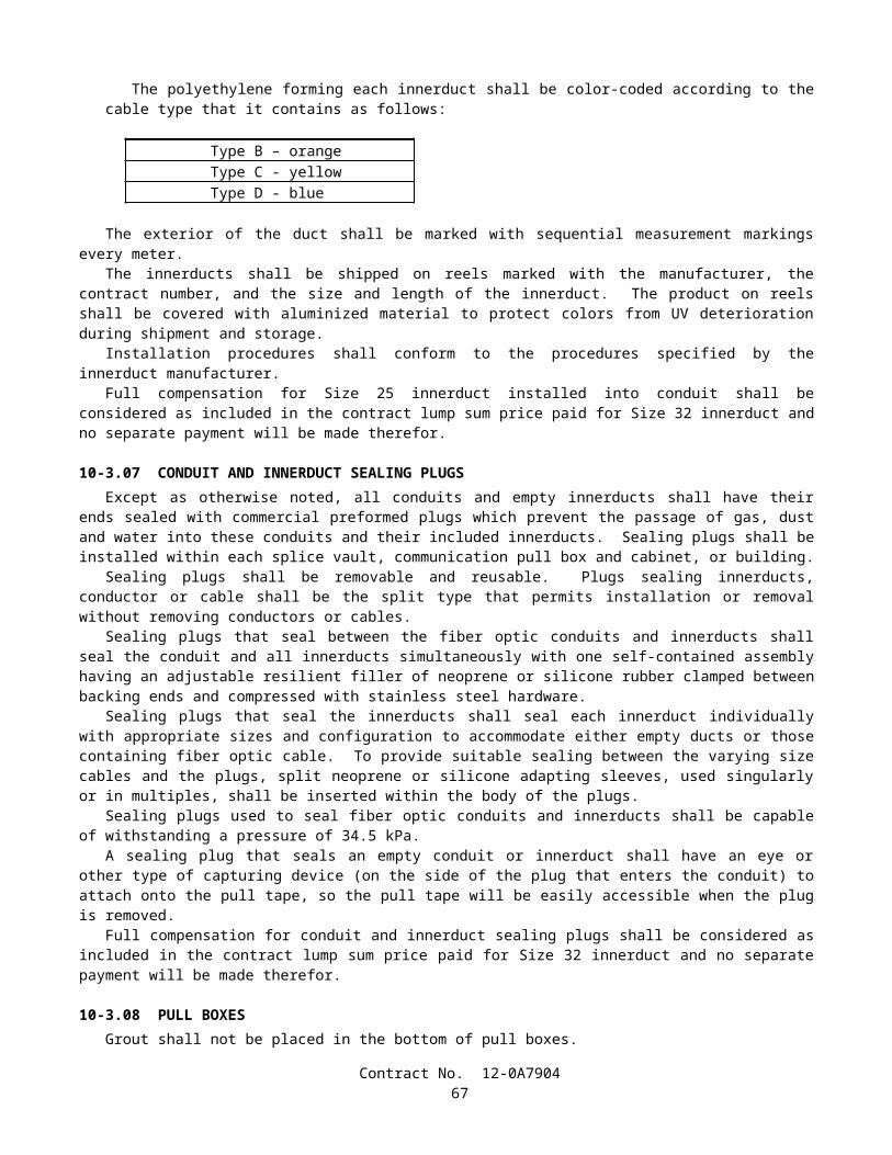
In developing the distribution interconnect package, each SC termination (pigtail or jumper) shall be tested for insertion attenuation loss with the use of an optical power meter and source. In addition, all singlemode terminations shall be tested for return reflection loss. These values shall meet the loss requirements specified earlier and shall be recorded on a tag attached to the pigtail or jumper.
Once assembly is complete, the manufacturer shall visually verify that all tagging, including loss values, is complete. Then as a final quality control measure, the manufacturer shall do an "end to end" optical power meter/light source test from pigtail end to jumper lead end to assure continuity and overall attenuation loss values.
The final test results shall be recorded, along with previous individual component values, on a special form assigned to each FDU. The completed form shall be dated and signed by the Manufacturer's Quality Control supervisor. One copy of this form will be attached in a plastic envelope to the assembled FDU unit. Copies will be provided separately to the Contractor and to the Engineer, and shall be also be maintained on file by the manufacturer or supplier.
The assembled and completed FDU unit shall then be protectively packaged for shipment to the Contractor for installation.
FIBER OPTIC SYSTEM GAIN MARGINThe installed system gain margin shall be at least 6 dB for each and every link. If the design system gain margin is
less than 6 dB, the Engineer shall be notified and informed of the Contractor's plan to meet that requirement.
ACTIVE COMPONENT TESTINGThe transmitters and receivers shall be tested with a power meter and light source, to record the transmitter average
output power (dBm) and receiver sensitivity (dBm). These values shall be recorded in the Link Loss Budget Worksheet shown in Appendix A.
SYSTEM VERIFICATION AT COMPLETION
OTDR Testing.--Once the passive cabling system has been installed and is ready for activation, 100 percent of the fiber links shall be tested with the OTDR for attenuation. Test results shall be recorded, dated, compared and filed with previous copies. A hard copy printout and a electronic copy of the traces and test results along with a licensed copy of the associated software on a DOS based 89 mm disk shall be submitted to the Engineer. If the OTDR test results are unsatisfactory the link shall be replaced at the Contractor's expense. The new link shall then be tested to demonstrate acceptability. Copies of the test results shall be submitted to the Engineer.
Installed System Link Loss Budget.--The Link Loss Budget Worksheet shown in Appendix A shall be completed for each link in the fiber optic system, using the data gathered throughout the installation process. The completed worksheets shall be included as part of the system documentation.
The Total System Gain shall be calculated by subtracting the measured Optical Receiver Sensitivity (line 1B on The Link Loss Budget Worksheet) from the measured Optical Transmitter Average Power (line 1A), which were obtained using a power meter and source. The resulting difference shall be the maximum allowable loss between the transmitter and the receiver, within 0 percent to +10 percent of the manufacturers specified loss budget for the transmitter/receiver pair. The Total System Gain shall be recorded on line 1C.
The Fiber Losses for a link shall be calculated by multiplying the length of the fiber link (line 2A) by the normalized cable attenuation (dB/km, line 2B) at the operating wavelength. The normalized attenuation for this calculation shall be the maximum value throughout the operating temperature range of the cable. The product shall be recorded on line 2C.
The total connector losses shall be calculated by summing the individual attenuation values for each connector pair in the link, excluding the transmitter and receiver connectors. The sum shall be recorded on line 2D.
The total splice losses shall be calculated by summing the individual attenuation values for each splice in the link. The sum shall be recorded on line 2E.
The total of other losses shall be calculated by summing the individual attenuation values for each component in the link not previously addressed. The sum shall be recorded on line 2F. These items may include, but are not limited to, couplers, splitters, routers and switches.
The Total System Loss shall be recorded on line 2G of the Link Loss Budget Worksheet.The Design System Gain Margin shall be calculated by subtracting the Total System Loss (line 2G) from the Total
System Gain (line 1C). The resulting difference shall be recorded on line 3A. The Contractor's attention is directed to "F/O System Gain Margin," elsewhere in these special provisions.
Power Meter and Light Source.--At the conclusion of the final OTDR testing, 100 percent of all fibers shall be tested end to end with a power meter and light source, in accordance with EIA Optical Test Procedure 171 and in the same wavelengths specified for the OTDR tests. These tests shall be conducted in both directions. Test results shall be
Contract No. 12-0A790467
recorded, compared and proven to be within the design link loss budgets, and filed with the other recordings of the same links. Test results shall be submitted to the Engineer.
Test Failures.--If during any of these system verification tests, the results prove to be unsatisfactory, the F/O cable will not be accepted. The unsatisfactory segments of cable shall be replaced with a new segment of cable at the Contractor's expense. The new segment of cable shall undergo the same testing procedure to determine acceptability. Copies of the test results shall be submitted to the Engineer. The removal and replacement of a segment of cable shall be interpreted as the removal and replacement of a single contiguous length of cable connecting two splices, two connectors, or a splice and a connector. The removal of only the small section containing the failure and therefore introducing new unplanned splices, will not be allowed.
Contract No. 12-0A790468

APPENDIX A
Cable Verification WorksheetEnd-to-End Attenuation (Power Meter and Light Source) Testing
and OTDR Testing
Contract No. ____________ Contractor: ____________________
Operator: _______________ Date: ______________
Link Number: ___________ Fiber Number: ____________
Test Wavelength (Circle one): 1310 nm 1550 nm
Expected Location of fiber ends: End 1: ___________ End 2: ___________
Power Meter and Light Source Test Results:Power In: Output Power:Insertion Loss [1A - 1B]:
_________ dBm_________ dBm_________ dB
1A1B1C
OTDR Test Results:Forward Loss: Reverse Loss:Average Loss [(2A + 2B)/2]:
_________ dB_________ dB_________ dB
2A2B2C
---------------------------------------------------------------------------------------------To Be Completed by Caltrans: Resident Engineer's Signature: ____________________Cable Link Accepted: ____________________________
Contract No. 12-0A790469

APPENDIX BFiber System Performance Margin Calculations Worksheet
A. Calculate the Passive Cable Attenuation
1. Calculate Fiber Loss at Operating Wavelength: _____ nm
Cable Distance (times) Individual Fiber Loss (equal) @ 1310 nm (0.4 dB/km) @ 1550 nm (0.3 dB/km)
_____ km x ___ dB/km =
Total Fiber Loss: _______ dB
B. Calculate the Total Connector/Splice Loss
2. Calculate Connectors/couplers Loss:(exclude Tx and Rx connectors)
Individual Connector Loss (times) Number of Connector Pairs (equal) Total Connector Loss:
0.4 dB x ____ =
_______ dB3. Calculate Splice Loss: Individual Splice Loss (times)
Number of Splices (equal) Total Splice Loss:
0.1 dB x ____ =_______ dB
4. Calculate Other Components Loss: Total Components: _______ dB
5. Calculate Total Losses: Total Connector Loss (plus)Total Splice Loss (plus)Total Components (equal)
+ dB+ dB+ dB =
Total Connector/Splice Loss: _______ dB
C. Calculate Active Component Link Loss Budget
System Wavelength:Fiber Type:Average Transmitter Output (Launch Power):
_______ nmsinglemode
______ dBmReceiver MAX Sensitivity (109 BER) (minus)Receiver MIN Sensitivity (equal)
Receiver Dynamic Range:
______ dBm- ______ dBm =
_______ dB6. Calculate Active ComponentLink Loss Budget:
Average Transmitter Output(Launch Power) (minus)Receiver MAX Sensitivity (equal)
______ dBm- ______ dBm =
Active Component Link Loss Budget: _______ dB
D. Verify Performance7. Calculate System Performance Margin to Verify Adequate Power:
Active Component Link Loss Budget [C] (minus)Passive Cable Attenuation [A] (minus)Total Connector/Splice Lost [B] (equal)
______ dB- ______ dB- ______ dB =
System Performance Margin: _______ dB
Contract No. 12-0A790470

APPENDIX C
Optical Modem TestWorksheet
Contract No. ____________ Contractor: ____________________
Operator: _______________ Date: ______________
Location: ________________
DS-1 Optical Modem, Modem No. :Optical Receiver Power (max) into modem (109 BER)Optical Receiver Level (minimum) into modemReceiver Dynamic Range (3A-3B):
_________ dB_________ dB_________ dB
3A3B3C
DS-1 Optical Modem, Modem No. :Optical Receiver Power (max) into modem (109 BER)Optical Receiver Level (minimum) into modemReceiver Dynamic Range (4A-4B):
_________ dB_________ dB_________ dB
4A4B4C
DS-1 Optical Modem, Modem No. :Optical Receiver Power (max) into modem (109 BER)Optical Receiver Level (minimum) into modemReceiver Dynamic Range (5A-5B):
_________ dB_________ dB_________ dB
5A5B5C
DS-1 Optical Modem, Modem No. :Optical Receiver Power (max) into modem (109 BER)Optical Receiver Level (minimum) into modemReceiver Dynamic Range (6A-6B):
_________ dB_________ dB_________ dB
6A6B6C
Contract No. 12-0A790471

10-8.05 VIDEO LINK TESTINGThe Contractor shall test the following video links:
1. Between cable node and corresponding field camera sites.2. Between hub and the corresponding field camera sites.
The video link testing shall be conducted after the Contractor submits a test plan and receives approval from the Engineer, based on these special provisions, plans and the manufacturer's recommended test procedures for the equipment involved. Measurements shall be made from the baseband-in (output of camera control receiver) to baseband-out connections. A video communication link shall include a video transmitter, video receiver, interconnecting optical fiber, connectors and power supplies. The video link is to provide point-to-point transmission and reception of a full motion NTSC baseband video signal using an optical fiber as the transmission medium. Video system performance tests for any particular video link shall be performed after the associated camera has been installed and tested.
Each video link in the communications system shall be tested with a video test signal at the transmitter input. The Contractor shall perform all level adjustments and alignments required on the video link in order for it to operate in accordance with these special provisions. If any video link fails to meet the performance requirements, the Contractor shall take all steps necessary to restore the failed link to the required performance.
Each video link in the communications system shall be tested for qualitative performance with its associated camera turned on and connected to the BNC connector of the video link transmitter. The Contractor shall measure and record the received optical power at the optical connector of the video receiver from the video transmitter under test using a 90 percent APL (average picture level) flat field input to the transmitter. The Contractor shall measure, record and tabulate the receiver's dynamic range at the optical connector of the video receiver from the video transmitter under test using a 90 percent APL (average picture level) flat field input to the transmitter. To do this the measured optical attenuation of the fiber being used shall be increased to the point at which the video test set just begins to show a 3 dB degradation of the video signal to noise ratio in accordance with EIA-250-C video test procedures. The optical receive power into the video receiver shall be measured and recorded. Then the optical attenuation shall be decreased until the video test set once again shows degradation of the video and registers errors. At no time shall the optical power into the receiver exceed the manufacturer's specified saturation level. The optical receive level shall once again be measured and recorded. These minimum and maximum receive levels define the video receiver's dynamic range and shall meet or exceed the specifications as specified elsewhere under these special provisions. This measurement shall be repeated for each link. The video test set shall be approved by the Engineer. The Contractor shall measure and record the baseband video output level from the video receiver under test. These measurements shall be repeated for each link.
The output video signal shall be connected to a monitor. The observed picture on the monitor shall be assessed for qualitative performance. All qualitative comments shall be recorded for each camera. The Contractor shall measure, record and tabulate the receiver's dynamic range at the optical connector of the video demultiplexer's receiver from the video multiplexer's transmitter under test. To do this the measured optical attenuation of the fiber being used shall be increased to the point at which the video test set just begins to show a 3 dB degradation of the video signal to noise ratio in accordance with EIA 250-C video test procedures. The optical receive power into the video receiver shall be measured and recorded. Then the optical attenuation shall be decreased until the video test set once again shows degradation of the video and registers errors. At no time shall the optical power into the receiver exceed the manufacturer's specified saturation level. The optical receive level shall once again be measured and recorded. These minimum and maximum receive levels define the video demultiplexer receiver's dynamic range and shall meet or exceed the specifications as specified elsewhere under these special provisions. This measurement shall be repeated for each link. The video test set shall be approved by the Engineer. Each video link shall be tested for the following performance characteristics. The Contractor shall measure, record and demonstrate that the performance meets or exceeds the specified EIA 250-C medium haul requirements listed below:
Differential gainDifferential phaseChrominance to luminance delay inequalityFrequency response characteristicSignal to noise ratioSignal to low frequency noiseSignal-to-periodic-noiseOutput signal level
Contract No. 12-0A790472

At the cable node, the Contractor shall use a temporary video receiver (VR) and monitor to receive a video signal for visual verification.
At the existing hub, the Contractor shall use a temporary monitor to receive a video signal for visual verification.
10-8.06 DATA LINK TESTINGThe Contractor shall test the following data links:
1. Between cable node and the corresponding field elements.2. Between hub and the corresponding field elements.3. Between hub and cable node.
A 15 minute BERT shall be performed between each TDM and each drop of each circuit at 9600 baud. For each of the four elements which are CCTV, CMS, ramp metering and traffic signal, the Contractor shall be provided
a software by Caltrans for PC laptop to communicate to each of the field elements, such as retrieve data and/or control the element from both cable node and hub. The Contractor shall record and deliver the last results of each field elements to the Engineer.
10-8.07 TIME DIVISION MULTIPLEXER TESTING
Pre-installation testing of the TDM equipmentPre-installation testing of the TDM equipment relates to tests of all material and equipment associated with the TDM in a
laboratory or bench-test environment prior to delivery to the site. Use of laboratory facilities, including an environmental simulation chamber, shall be arranged by the Contractor. The tests shall either be conducted at the equipment manufacturer's premises, at the Contractor's laboratory, or at Caltrans Transportation Laboratory, 5900 Folsom Boulevard, Sacramento, CA 95816, telephone number (916) 227-7028.
All TDM materials and equipment, test equipment and special tools, shall be bench tested in accordance with this section, and the section entitled "Pre-Installation Testing" mentioned elsewhere in these special provisions. Test equipment and special tools, if required, shall be provided and noted for the tests.
A test plan shall be provided to the Engineer for approval and to Caltrans, Office of Electrical Systems, 1120 N Street, MS 36, Sacramento, CA 95814, Attention: Senior Telecommunications Electrical Engineer, for information. The test plan shall comply with the TDM equipment manufacturer's requirements and guidelines and shall be setup according to communication system plan which shall include, but not limited to:
A. T1 and DS1 testing between TDMs which shall demonstrate channel bank, drop and insert and dual channel bank modes.
B. 56/64 kbps x N high speed data circuit testing over the TDM..
The certified results of the tests, if not performed at the Caltrans Transportation Laboratory, shall be submitted to the Engineer and to Caltrans, Office of Telecommunications, 1120 N Street, M.S. 77, Sacramento, CA 95814, Attention: Senior Telecommunications Electrical Engineer prior to field installation of the TDM equipment.
Field Installation of TDM equipmentAfter installation and acceptance by the Engineer of the fiber optic cable plant, node structures and traffic elements, etc.,
the TDM equipment and any ancillary items shall be started and installed by an authorized customer support representative from the equipment manufacturer. The installation of TDM equipment shall include, but not limited to FODMs to the appropriate channel units/cards, set synchronization of the TDMs in the communication system and the initial startup and/or configuration of the DS0 maps. The representative shall have prior hands-on experience in the installation and testing of traffic management systems which utilize TDM equipment. It is the responsibility of the Contractor to provide an authorized manufacturer's representative or technician with this minimum level of qualification and representation for the installation of TDM equipment at the data node, hub and TMC.
Post Installation test of TDM system linksThe post installation test is for the alignment and testing of the TDM system links using external test equipment and test
patterns and using State-furnished software where appropriate. The test shall be conducted in accordance to an approved installation and test plan. The test equipment to externally test the digital signals over the TDM system links shall be a TTC Fireberd 6000 or equal. The Contractor shall be responsible to adjust levels required for the TDM system to operate.
Contract No. 12-0A790473

The links shall be tested in accordance with the sections entitled "Data Link Testing" and "Acceptance Testing" elsewhere in these special provisions.
The activities shall be staged accordingly and shall include verification of all circuits in this contract's communication network with the following tests, as a minimum:
RS-232 multipoint or multidrop asynchronous data circuit testing between a host master over one multidrop circuit using a minimum of five FODM slaves to demonstrate the multipoint data being dropped off at the same DS0 and subrate channel within that DS0.
The "future use" channel cards shall be tested by temporarily installing them in active slots and then repeating the tests as directed above in these special provisions.
10-8.08 ACCEPTANCE TESTINGAcceptance testing includes the preparation of an acceptance test plan, conducting acceptance tests and subsequent
retests, and documentation of the results.Final acceptance tests shall be conducted after the site test results have been reviewed and accepted by the Engineer.
These tests include the complete system in normal operations.The Contractor shall submit five copies of the acceptance test plan to the Engineer for approval prior to commencement
of acceptance testing. The acceptance test plan shall address the full testing requirements of the specifications. The acceptance test plan shall detail all tests to be performed, the test results which are expected and the test schedule. The acceptance test plan will include the following major test and acceptance categories:
Physical inspection.Performance tests.Functional tests.
The Contractor shall test the communication system according to the approved acceptance test plan and shall provide all test equipment, labor and ancillary items required to perform the testing. The test equipment shall be certified to be calibrated to the manufacturers' specifications. The model and part numbers and date of last calibration of all test equipment shall be included with the test results.
Acceptance testing shall not commence until all material required by the Contract is delivered, installed, and aligned and all production test and site test documentation and results have been approved by the Engineer.
All acceptance test results shall be fully documented and such documentation provided as a condition of acceptance.
Physical InspectionThe Contractor shall provide documentation to prove delivery of all material, equipment, cable and documentation. If
any material or documentation is outstanding or have been replaced under pre-acceptance warranty a physical inspection and documentation shall be provided for this material. The physical inspection shall consist of inspecting all installed material to ensure workmanship satisfies the specified requirements.
Performance TestsThe Contractor shall test the video subsystem and record the results:
The video signal to noise shall be measured according to EIA-250C. The video signal to noise ratio shall be measured and recorded with suitable video test equipment providing the video reference signal. The video signal to noise ratio shall be greater than 47 dB.
The video signal to low frequency noise ratio shall be measured according to EIA-250C. The resulting video signal to low frequency noise ratio shall be greater than 39 dB. If a AGC circuit does not allow measurement as per EIA-250C, the Contractor shall submit an alternative test plan for approval.
The video signal to periodic noise ratio shall be measured according to EIA-250C. The resulting video signal to periodic noise ratio shall be greater than 52 dB.
Data tests shall be performed on all operational and voice data circuits. The central computer and the controller in the field shall be temporarily disconnected from the circuit under test for the connection of appropriate test equipment for the measurement of the following parameters:
Contract No. 12-0A790474
A data test set shall be used at the remote modems to insert an asynchronous pseudo-random pattern using 8 data bits, 1 start bit, 1 stop bit and even parity. The data test set at the remote modem must hold RTS high for the duration of the data test. The data rate of the test sets shall be set to the rate used in the system.
A 15 minute test on each drop of each multipoint circuit shall be error free in both directions.One drop of each circuit, as chosen by the Engineer, shall be tested for 48 hours. The average bit error rate in both
directions shall be less than 5 x 10⁻⁸.The round-trip propagation delay for each Model 170 controller circuit shall be measured by using a loopback
connector on the slave modem furthest from the master. The loopback connector shall connect pin 2 to 3, 8 to 4, and 6 to 20 of the DB-25 connector. A data test set capable of measuring delay shall be used at the different toll plazas. The test shall be repeated 3 times and the average value calculated.
Pulse-width distortion shall be defined as the difference between the data pulse width into a data channel port at the different toll plaza port and the pulse width out of the EIA-232C port of an interconnected drop modem.
Distortion shall be tested between the different toll plaza and the selected field modem for each data circuit. The signal shall not have a gross start-stop distortion greater than 20 percent at any data interface, measured as per EIA-404-A.
If any circuit or element fails to satisfy the specified performance requirements, the Contractor shall determine the cause and remedy the failure to the satisfaction of the Engineer. The full performance tests shall be repeated under operating conditions as determined by the Engineer.
Functional TestsThe Contractor shall test in the presence of the Engineer all integrated system functions to demonstrate that all circuits,
cameras, camera control, and all equipment satisfies the functional requirements of the specifications.Functional testing shall include subjective testing of each camera image and verification of camera control from the
camera control unit. The connectivity of each data channel shall be demonstrated.The Engineer may assist the Contractor in conducting functional tests, as required, and the Contractor shall document all
functional test results.In the event that any aspect of the functional tests are determined by the Engineer to have failed, the Contractor shall
cease all acceptance testing and determine the cause of the failure. If the failure is due to a defect within the Contractor furnished portion of the system, the Contractor shall make repairs to the approval of the Engineer. Acceptance testing shall, at the discretion of the Engineer, be repeated from the start of functional tests.
Final AcceptanceThe system will not be accepted until all of the following conditions have been met as follows:
Physical, performance, and functional acceptance tests have been completed and the results are approved by the Engineer.
All documentation has been completed and submitted to the Engineer.All connections that were changed to perform acceptance tests are restored and tested.
Upon completion of acceptance tests the Contractor shall connect all equipment to form a fully operational system.
10-8.09 SYSTEM DOCUMENTATIONThe Contractor shall submit a draft copy of all documentation for review and approval prior to production of
documentation. The Engineer will review and approve or reject the draft documentation within four weeks of receipt.The Contractor shall modify the documentation if required and submit provisional documentation. The Engineer will
approve or reject the provisional documentation within three weeks of receipt. The Contractor shall arrange for re-submission in a timely manner to meet the schedule in the case that the documents are being rejected.
Draft documentation shall be submitted eight weeks prior to the start of installation. The draft documentation shall show the general approach in preparing the final manuals.
Upon approval of the draft documentation, provisional documentation shall be supplied 3 weeks prior to the start of site testing. The provisional documentation shall be of the same format as the final manuals but with temporary insertion for items which cannot be finalized until the system is completed, tested and accepted. Final documentation shall be submitted no later than 4 weeks after completion of the acceptance tests and shall incorporate all comments made during the approval stages. The Contractor shall be responsible for all delay caused by non-compliance to the specified requirements.
Final documentation shall be approved prior to its production.Ten copies of all final documents shall be delivered. The copies shall be 215 mm x 279 mm and bound in three-ring,
hard-covered binders, complete with dividers.
Contract No. 12-0A790475
Documentation shall consist of the following types of manuals and drawings and shall include the information described.The operations and maintenance manual shall provide all the information necessary to operate, maintain and repair the
equipment and cable to the lowest module or component level. It shall contain as a minimum the following:
Master Items IndexThe master items index section shall be the first section of the O & M manual. The section shall describe the
purpose of each manual and brief description to the directory of the manual. It shall also reference equipment manuals as required for additional and support material.
System Description and Technical DataThe system description and technical data section of the operations and maintenance manual shall contain an overall
description of the system and associated equipment and cables with illustrative block diagrams. This section shall identify all equipment and cables in the system stating the exact module and option number that are employed in the system. Technical data, specification and settings for every type of equipment or cable shall be provided. Any modification that has been done on the equipment shall be clearly described.
Theory of OperationThe manual shall contain a theory of operation section providing functional description of each element of the
system, explaining how each function is being achieved separately and how each element works together to form the complete system.
Configuration of Hardware and Software DocumentationThe operations and maintenance manual shall provide proper documentation for all configuration of hardware and
software. The configuration of hardware and software documentation shall include a clear description of the system's functionalities and specifications. Description on each configuration of hardware and software modules and programs shall be provided.
OperationsThe operations and maintenance manual shall describe how to operate the system and each particular type of
equipment and software. Equipment layout, layout of controls, displays, software operating procedures and all other information required to correctly operate the system and each functional unit shall be provided. Procedures shall also be provided for initial tune-up of the system and adjustment and checkout required to ensure that the system is functioning within the performance requirements. Warning of special procedures shall be given. The functions and setting of all parameters shall be explained.
Corrective MaintenanceThe operations and maintenance manual shall include fault diagnostic and repair procedures to permit locating and
correcting faults at the replaceable module level. Procedures shall include alignment and testing of the equipment following repair, the test equipment, tools, diagnostic software required and the test set up.
Preventative MaintenanceThe operations and maintenance manual shall include procedures for preventative maintenance in order to maintain
the performance parameters of the system, equipment and cables within the requirements of the specifications.
Parts ListThe operations and maintenance manual shall include a list of all replaceable parts with exact parts description and
number and a directory of recommended suppliers with correspondence address, telephone and fax numbers.
Test ResultsThe test result section of the operations and maintenance shall include a copy of the results for all the tests that have
been conducted by the Contractor.
System schematic drawings shall be provided to identify the type of equipment at each location and the function of all equipment. The drawings shall also show how the system is interconnected. A comprehensive list of cabling and wiring shall be provided to clearly identify the interconnection and labeling of all equipment both in the field, at existing cable node, at existing hub, and at the TMC.
Contract No. 12-0A790476

10-8.10 PAYMENTThe contract lump sum price paid for system testing and documentation shall include full compensation for furnishing all
labor, materials, tools, equipment, and incidentals, and for doing all the work involved in system testing and documentation, complete in place, as shown on the plans, as specified in the Standard Specifications and these special provisions, and as directed by the Engineer.
SECTION 11. MODIFIED STANDARD SPECIFICATION SECTIONS
SECTION 11-1. (BLANK)
SECTION 11-2. PORTLAND CEMENT CONCRETE
11-2.01 GENERALPortland cement concrete shall conform to the provisions in this Section 11-2, "Portland Cement Concrete," and the
section entitled "Portland Cement Concrete" in Section 8, "Materials," of these special provisions. Section 90, "Portland Cement Concrete," of the Standard Specifications is deleted. Section 90, "Portland Cement Concrete," of the Standard Specifications is amended to read as follows.
SECTION 90: PORTLAND CEMENT CONCRETE90-1 GENERAL
90-1.01 DESCRIPTION Portland cement concrete shall be composed of cementitious material, fine aggregate, coarse aggregate, admixtures
if used, and water, proportioned and mixed as specified in these specifications. The Contractor shall determine the mix proportions for all concrete except pavement concrete. The Engineer will
determine the mix proportions for pavement concrete. Concrete for which the mix proportions are determined either by the Contractor or the Engineer shall conform to the requirements of this Section 90.
Unless otherwise specified, cementitious material shall be a combination of cement and mineral admixture. Cementitious material shall be either:
1. "Type IP (MS) Modified" cement; or 2. A combination of "Type II Modified" portland cement and mineral admixture; or3. A combination of Type V portland cement and mineral admixture.
Type III portland cement shall be used only as allowed in the special provisions or with the approval of the Engineer.
Class 1 concrete shall contain not less than 400 kg of cementitious material per cubic meter. Class 2 concrete shall contain not less than 350 kg of cementitious material per cubic meter. Class 3 concrete shall contain not less than 300 kg of cementitious material per cubic meter. Class 4 concrete shall contain not less than 250 kg of cementitious material per cubic meter. Minor concrete shall contain not less than 325 kg of cementitious material per cubic meter unless otherwise
specified in these specifications or the special provisions. Unless otherwise designated on the plans or specified in these specifications or the special provisions, the amount of
cementitious material used per cubic meter of concrete in structures or portions of structures shall conform to the following:
Contract No. 12-0A790477

Use Cementitious Material Content(kg/m3)
Concrete designated by compressive strength:Deck slabs and slab spans of bridgesRoof sections of exposed top box culvertsOther portions of structures
400 min., 475 max.400 min., 475 max.350 min., 475 max.
Concrete not designated by compressive strength:Deck slabs and slab spans of bridgesRoof sections of exposed top box culvertsPrestressed membersSeal coursesOther portions of structures
400 min.400 min.400 min.400 min.350 min.
Concrete for precast members 350 min., 550 max.
Whenever the 28-day compressive strength shown on the plans is greater than 25 MPa, the concrete shall be designated by compressive strength. If the plans show a 28-day compressive strength that is 28 MPa or greater, an additional 14 days will be allowed to obtain the specified strength. The 28-day compressive strengths shown on the plans that are 25 MPa or less are shown for design information only and are not a requirement for acceptance of the concrete.
Concrete designated by compressive strength shall be proportioned such that the concrete will attain the strength shown on the plans or specified in the special provisions.
Before using concrete for which the mix proportions have been determined by the Contractor, or in advance of revising those mix proportions, the Contractor shall submit in writing to the Engineer a copy of the mix design.
Compliance with cementitious material content requirements will be verified in conformance with procedures described in California Test 518 for cement content. For testing purposes, mineral admixture shall be considered to be cement. Batch proportions shall be adjusted as necessary to produce concrete having the specified cementitious material content.
If any concrete has a cementitious material, portland cement, or mineral admixture content that is less than the minimum required, the concrete shall be removed. However, if the Engineer determines that the concrete is structurally adequate, the concrete may remain in place and the Contractor shall pay to the State $0.55 for each kilogram of cementitious material, portland cement, or mineral admixture that is less than the minimum required. The Department may deduct the amount from any moneys due, or that may become due, the Contractor under the contract. The deductions will not be made unless the difference between the contents required and those actually provided exceeds the batching tolerances permitted by Section 90-5, "Proportioning." No deductions will be made based on the results of California Test 518.
The requirements of the preceding paragraph shall not apply to minor concrete or commercial quality concrete.
90-2 MATERIALS
90-2.01 CEMENT Unless otherwise specified, cement shall be either "Type IP (MS) Modified" cement, "Type II Modified" portland
cement or Type V portland cement. "Type IP (MS) Modified" cement shall conform to the requirements for Type IP (MS) cement in ASTM
Designation: C 595, and shall be comprised of an intimate and uniform blend of Type II cement and not more than 35 percent by mass of mineral admixture. The type and minimum amount of mineral admixture used in the manufacture of "Type IP (MS) Modified" cement shall be in conformance with the provisions in Section 90-4.08, "Required Use of Mineral Admixtures."
"Type II Modified" portland cement shall conform to the requirements for Type II portland cement in ASTM Designation: C 150.
In addition, "Type IP (MS) Modified" cement and "Type II Modified" portland cement shall conform to the following requirements:
A. The cement shall not contain more than 0.60 percent by mass of alkalies, calculated as the percentage of Na2O plus 0.658 times the percentage of K2O, when determined by either direct intensity flame photometry or by the atomic absorption method. The instrument and procedure used shall be qualified as to precision and accuracy in conformance with the requirements in ASTM Designation: C 114;
B. The autoclave expansion shall not exceed 0.50 percent; and
Contract No. 12-0A790478
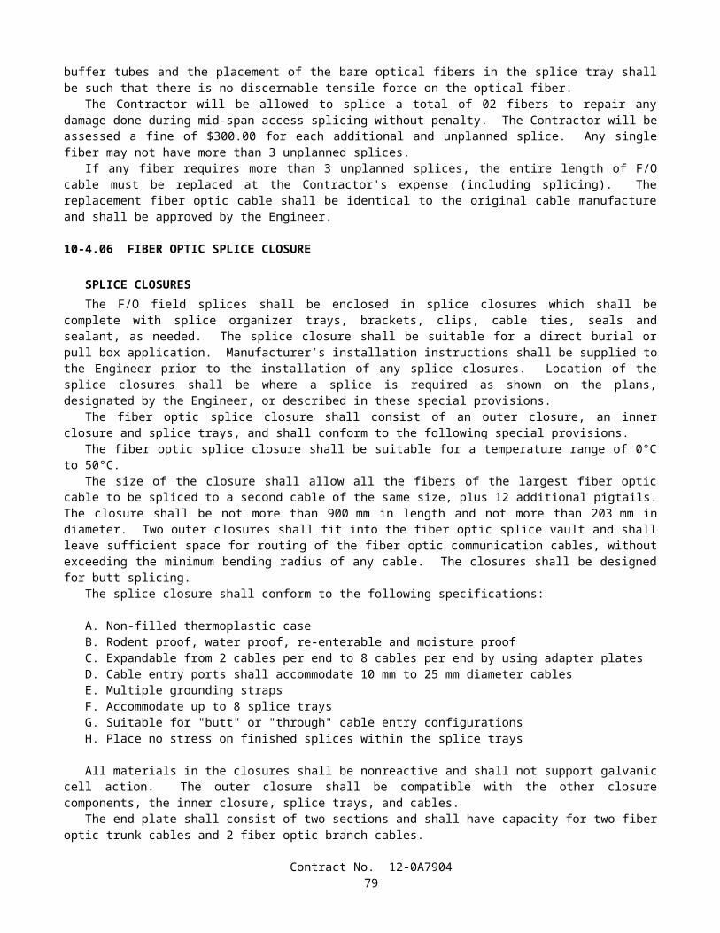
C. Mortar, containing the cement to be used and Ottawa sand, when tested in conformance with California Test 527, shall not expand in water more than 0.010 percent and shall not contract in air more than 0.048 percent, except that when cement is to be used for precast prestressed concrete piling, precast prestressed concrete members, or steam cured concrete products, the mortar shall not contract in air more than 0.053 percent.
Type III and Type V portland cements shall conform to the requirements in ASTM Designation: C 150 and the additional requirements listed above for "Type II Modified" portland cement, except that when tested in conformance with California Test 527, mortar containing Type III portland cement shall not contract in air more than 0.075 percent.
Cement used in the manufacture of cast-in-place concrete for exposed surfaces of like elements of a structure shall be from the same cement mill.
Cement shall be protected from exposure to moisture until used. Sacked cement shall be piled to permit access for tally, inspection, and identification of each shipment.
Adequate facilities shall be provided to assure that cement meeting the provisions specified in this Section 90 -2.01 shall be kept separate from other cement in order to prevent any but the specified cement from entering the work. Safe and suitable facilities for sampling cement shall be provided at the weigh hopper or in the feed line immediately in advance of the hopper, in conformance with California Test 125.
If cement is used prior to sampling and testing as provided in Section 6-1.07, "Certificates of Compliance," and the cement is delivered directly to the site of the work, the Certificate of Compliance shall be signed by the cement manufacturer or supplier of the cement. If the cement is used in ready-mixed concrete or in precast concrete products purchased as such by the Contractor, the Certificate of Compliance shall be signed by the manufacturer of the concrete or product.
Cement furnished without a Certificate of Compliance shall not be used in the work until the Engineer has had sufficient time to make appropriate tests and has approved the cement for use.
90-2.02 AGGREGATES Aggregates shall be free from deleterious coatings, clay balls, roots, bark, sticks, rags, and other extraneous material. Natural aggregates shall be thoroughly and uniformly washed before use. The Contractor, at the Contractor's expense, shall provide safe and suitable facilities, including necessary splitting
devices for obtaining samples of aggregates, in conformance with California Test 125. Aggregates shall be of such character that it will be possible to produce workable concrete within the limits of water
content provided in Section 90-6.06, "Amount of Water and Penetration." Aggregates shall have not more than 10 percent loss when tested for soundness in conformance with the
requirements in California Test 214. The soundness requirement for fine aggregate will be waived, provided that the durability index, Df, of the fine aggregate is 60, or greater, when tested for durability in conformance with California Test 229.
If the results of any one or more of the Cleanness Value, Sand Equivalent, or aggregate grading tests do not meet the requirements specified for "Operating Range" but all meet the "Contract Compliance" requirements, the placement of concrete shall be suspended at the completion of the current pour until tests or other information indicate that the next material to be used in the work will comply with the requirements specified for "Operating Range."
If the results of either or both the Cleanness Value and coarse aggregate grading tests do not meet the requirements specified for "Contract Compliance," the concrete that is represented by the tests shall be removed. However, if the Engineer determines that the concrete is structurally adequate, the concrete may remain in place, and the Contractor shall pay to the State $4.60 per cubic meter for paving concrete and $7.20 per cubic meter for all other concrete for the concrete represented by these tests and left in place. The Department may deduct the amount from any moneys due, or that may become due, the Contractor under the contract.
If the results of either or both the Sand Equivalent and fine aggregate grading tests do not meet the requirements specified for "Contract Compliance," the concrete which is represented by the tests shall be removed. However, if the Engineer determines that the concrete is structurally adequate, the concrete may remain in place, and the Contractor shall pay to the State $4.60 per cubic meter for paving concrete and $7.20 per cubic meter for all other concrete for the concrete represented by these tests and left in place. The Department may deduct the amount from any moneys due, or that may become due, the Contractor under the contract.
The 2 preceding paragraphs apply individually to the "Contract Compliance" requirements for coarse aggregate and fine aggregate. When both coarse aggregate and fine aggregate do not conform to the "Contract Compliance" requirements, both paragraphs shall apply. The payments specified in those paragraphs shall be in addition to any payments made in conformance with the provisions in Section 90-1.01, "Description."
No single Cleanness Value, Sand Equivalent or aggregate grading test shall represent more than 250 m3 of concrete or one day's pour, whichever is smaller.
Aggregates specified for freeze-thaw resistance shall pass the freezing and thawing test, California Test 528.
Contract No. 12-0A790479

The Contractor shall notify the Engineer of the proposed source of freeze-thaw resistant concrete aggregates at least 4 months before intended use. Should the Contractor later propose a different source of concrete aggregates, the Contractor shall again notify the Engineer at least 4 months before intended use. Blending of fine or coarse aggregates from untested sources with acceptable aggregates will not be permitted. Provisions for the time of submission of samples as provided in Section 40-1.015, "Cement Content," are superseded by the foregoing.
Concurrently with notification of proposed sources of freeze-thaw resistant concrete aggregates, the Contractor shall furnish samples in the quantity ordered by the Engineer. The samples shall be secured under the direct supervision of the Engineer. Samples from existing stockpiles of processed aggregate shall be taken from washed materials and shall be visibly damp. Samples from materials in place in a material source shall be taken at depths from the existing surface that will ensure the presence of the full quantity of ground water. Excavations for the purpose of securing samples shall be made to the full depth of intended source operations. Samples shall be protected against loss of contained water until they are delivered to the Engineer.
The Engineer will waive the above freeze-thaw test and the 4-month advance notice, required in this Section, provided aggregates are to be obtained from sources that have previously passed this test and test results are currently applicable.
No extension of contract time will be allowed for the time required to perform the freezing and thawing test. When the source of an aggregate is changed, except for pavement concrete, the Contractor shall adjust the mix
proportions and submit in writing to the Engineer a copy of the mix design before using the aggregates. When the source of an aggregate is changed for pavement concrete, the Engineer shall be allowed sufficient time to adjust the mix, and the aggregates shall not be used until necessary adjustments are made.
90-2.02A Coarse Aggregate Coarse aggregate shall consist of gravel, crushed gravel, crushed rock, crushed air-cooled iron blast furnace slag or
combinations thereof. Crushed air-cooled blast furnace slag shall not be used in reinforced or prestressed concrete. Coarse aggregate shall conform to the following quality requirements:
TestsCalifornia
Test RequirementsLoss in Los Angeles Rattler (after 500 revolutions)
211 45% max.
Cleanness ValueOperating Range 227 75 min.Contract Compliance 227 71 min.
In lieu of the above Cleanness Value requirements, a Cleanness Value "Operating Range" limit of 71, minimum, and a Cleanness Value "Contract Compliance" limit of 68, minimum, will be used to determine the acceptability of the coarse aggregate if the Contractor furnishes a Certificate of Compliance, as provided in Section 6-1.07, "Certificates of Compliance," certifying that:
1. coarse aggregate sampled at the completion of processing at the aggregate production plant had a Cleanness Value of not less than 82 when tested by California Test 227; and
2. prequalification tests performed in conformance with the requirements in California Test 549 indicated that the aggregate would develop a relative strength of not less than 95 percent and would have a relative shrinkage not greater than 105 percent, based on concrete.
90-2.02B Fine Aggregate Fine aggregate shall consist of natural sand, manufactured sand produced from larger aggregate or a combination
thereof. Manufactured sand shall be well graded. Fine aggregate shall conform to the following quality requirements:
Contract No. 12-0A790480

TestCalifornia
Test RequirementsOrganic Impurities 213 Satisfactorya
Mortar Strengths Relative to Ottawa Sand 515 95%, min.Sand Equivalent:
Operating Range 217 75, min.Contract Compliance 217 71, min.
a Fine aggregate developing a color darker than the reference standard color solution may be accepted if it is determined by the Engineer, from mortar strength tests, that a darker color is acceptable.
In lieu of the above Sand Equivalent requirements, a Sand Equivalent "Operating Range" limit of 71 minimum and a Sand Equivalent "Contract Compliance" limit of 68 minimum will be used to determine the acceptability of the fine aggregate if the Contractor furnishes a Certificate of Compliance, as provided in Section 6-1.07, "Certificates of Compliance," certifying that:
1. fine aggregate sampled at the completion of processing at the aggregate production plant had a Sand Equivalent value of not less than 82 when tested by California Test 217; and
2. prequalification tests performed in conformance with California Test 549 indicated that the aggregate would develop a relative strength of not less than 95 percent and would have a relative shrinkage not greater than 105 percent, based on concrete.
90-2.03 WATER In conventionally reinforced concrete work, the water for curing, for washing aggregates, and for mixing shall be
free from oil and shall not contain more than 1000 parts per million of chlorides as Cl, when tested in conformance with California Test 422, nor more than 1300 parts per million of sulfates as SO4, when tested in conformance with California Test 417. In prestressed concrete work, the water for curing, for washing aggregates, and for mixing shall be free from oil and shall not contain more than 650 parts per million of chlorides as Cl, when tested in conformance with California Test 422, nor more than 1300 parts per million of sulfates as SO4, when tested in conformance with California Test 417. In no case shall the water contain an amount of impurities that will cause either: 1) a change in the setting time of cement of more than 25 percent when tested in conformance with the requirements in ASTM Designation: C 191 or ASTM Designation: C 266 or 2) a reduction in the compressive strength of mortar at 14 days of more than 5 percent, when tested in conformance with the requirements in ASTM Designation: C 109, when compared to the results obtained with distilled water or deionized water, tested in conformance with the requirements in ASTM Designation: C 109.
In non-reinforced concrete work, the water for curing, for washing aggregates and for mixing shall be free from oil and shall not contain more than 2000 parts per million of chlorides as Cl, when tested in conformance with California Test 422, or more than 1500 parts per million of sulfates as SO4, when tested in conformance with California Test 417.
In addition to the above provisions, water for curing concrete shall not contain impurities in a sufficient amount to cause discoloration of the concrete or produce etching of the surface.
Water reclaimed from mixer wash-out operations may be used in mixing concrete. The water shall not contain coloring agents or more than 300 parts per million of alkalis (Na2O + 0.658 K2O) as determined on the filtrate. The specific gravity of the water shall not exceed 1.03 and shall not vary more than ±0.010 during a day's operations.
90-2.04 ADMIXTURE MATERIALS Admixture materials shall conform to the requirements in the following ASTM Designations:
A. Chemical Admixtures—ASTM Designation: C 494.B. Air-entraining Admixtures—ASTM Designation: C 260.C. Calcium Chloride—ASTM Designation: D 98.D. Mineral Admixtures—Coal fly ash; raw or calcined natural pozzolan as specified in ASTM Designation: C618;
silica fume conforming to the requirements in ASTM Designation: C1240, with reduction of mortar expansion of 80 percent, minimum, using the cement from the proposed mix design.
Unless otherwise specified in the special provisions, mineral admixtures shall be used in conformance with the provisions in Section 90-4.08, "Required Use of Mineral Admixtures."
Contract No. 12-0A790481

90-3 AGGREGATE GRADINGS
90-3.01 GENERAL Before beginning concrete work, the Contractor shall submit in writing to the Engineer the gradation of the primary
aggregate nominal sizes that the Contractor proposes to furnish. If a primary coarse aggregate or the fine aggregate is separated into 2 or more sizes, the proposed gradation shall consist of the gradation for each individual size, and the proposed proportions of each individual size, combined mathematically to indicate one proposed gradation. The proposed gradation shall meet the grading requirements shown in the table in this section, and shall show the percentage passing each of the sieve sizes used in determining the end result.
The Engineer may waive, in writing, the gradation requirements in this Section 90-3.01 and in Sections 90-3.02, "Coarse Aggregate Grading," 90-3.03, "Fine Aggregate Grading," and 90-3.04, "Combined Aggregate Gradings," if, in the Engineer's opinion, furnishing the gradation is not necessary for the type or amount of concrete work to be constructed.
Gradations proposed by the Contractor shall be within the following percentage passing limits:
Primary Aggregate Nominal Size Sieve Size Limits of Proposed Gradation37.5-mm x 19-mm 25-mm 19 - 4125-mm x 4.75-mm 19-mm 52 - 8525-mm x 4.75-mm 9.5-mm 15 - 3812.5-mm x 4.75-mm 9.5-mm 40 - 78 9.5-mm x 2.36-mm 9.5-mm 50 - 85 Fine Aggregate 1.18-mm 55 - 75Fine Aggregate 600-µm 34 - 46Fine Aggregate 300-µm 16 - 29
Should the Contractor change the source of supply, the Contractor shall submit in writing to the Engineer the new gradations before their intended use.
90-3.02 COARSE AGGREGATE GRADING The grading requirements for coarse aggregates are shown in the following table for each size of coarse aggregate:
Percentage Passing Primary Aggregate Nominal Sizes37.5-mm x 19-mm 25-mm x 4.75-mm 12.5-mm x 4.75-mm 9.5-mm x 2.36-mm
Operating Contract Operating Contract Operating Contract Operating ContractSieve Sizes Range Compliance Range Compliance Range Compliance Range Compliance50-mm 100 100 — — — — — —37.5-mm 88-100 85-100 100 100 — — — —25-mm x ± 18 X ± 25 88-100 86-100 — — — —19-mm 0-17 0-20 X ± 15 X ± 22 100 100 — —12.5-mm — — — — 82-100 80-100 100 1009.5-mm 0-7 0-9 X ± 15 X ± 22 X ± 15 X ± 22 X ± 15 X ± 204.75-mm — — 0-16 0-18 0-15 0-18 0-25 0-282.36-mm — — 0-6 0-7 0-6 0-7 0-6 0-7
In the above table, the symbol X is the gradation that the Contractor proposes to furnish for the specific sieve size as provided in Section 90-3.01, "General."
Coarse aggregate for the 37.5-mm, maximum, combined aggregate grading as provided in Section 90-3.04, "Combined Aggregate Gradings," shall be furnished in 2 or more primary aggregate nominal sizes. Each primary aggregate nominal size may be separated into 2 sizes and stored separately, provided that the combined material conforms to the grading requirements for that particular primary aggregate nominal size.
When the 25-mm, maximum, combined aggregate grading as provided in Section 90-3.04, "Combined Aggregate Gradings," is to be used, the coarse aggregate may be separated into 2 sizes and stored separately, provided that the combined material shall conform to the grading requirements for the 25-mm x 4.75-mm primary aggregate nominal size.
Contract No. 12-0A790482

90-3.03 FINE AGGREGATE GRADING Fine aggregate shall be graded within the following limits:
Percentage PassingSieve Sizes Operating Range Contract Compliance
9.5-mm 100 1004.75-mm 95-100 93-1002.36-mm 65-95 61-991.18-mm X ± 10 X ± 13600-µm X ± 9 X ± 12300-µm X ± 6 X ± 9150-µm 2-12 1-1575-µm 0-8 0-10
In the above table, the symbol X is the gradation that the Contractor proposes to furnish for the specific sieve size as provided in Section 90-3.01, "General."
In addition to the above required grading analysis, the distribution of the fine aggregate sizes shall be such that the difference between the total percentage passing the 1.18-mm sieve and the total percentage passing the 600-µm sieve shall be between 10 and 40, and the difference between the percentage passing the 600-µm and 300-µm sieves shall be between 10 and 40.
Fine aggregate may be separated into 2 or more sizes and stored separately, provided that the combined material conforms to the grading requirements specified in this Section 90-3.03.
90-3.04 COMBINED AGGREGATE GRADINGS Combined aggregate grading limits shall be used only for the design of concrete mixes. Concrete mixes shall be
designed so that aggregates are combined in proportions that shall produce a mixture within the grading limits for combined aggregates as specified herein. Within these limitations, the relative proportions shall be as ordered by the Engineer, except as otherwise provided in Section 90-1.01, "Description."
The combined aggregate grading used in portland cement concrete pavement shall be the 37.5-mm, maximum grading.
The combined aggregate grading used in concrete for structures and other concrete items, except when specified otherwise in these specifications or the special provisions, shall be either the 37.5-mm, maximum grading, or the 25-mm, maximum grading, at the option of the Contractor.
Grading Limits of Combined AggregatesPercentage Passing
Sieve Sizes 37.5-mm Max. 25-mm Max. 12.5-mm Max. 9.5-mm Max.50-mm 100 — — —37.5-mm 90-100 100 — —25-mm 50-86 90-100 — —19-mm 45-75 55-100 100 —12.5-mm — — 90-100 1009.5-mm 38-55 45-75 55-86 50 - 1004.75-mm 30-45 35-60 45-63 45 - 632.36-mm 23-38 27-45 35-49 35 - 491.18-mm 17-33 20-35 25-37 25 - 37600-µm 10-22 12-25 15-25 15 - 25300-µm 4-10 5-15 5-15 5 - 15150-µm 1-6 1-8 1-8 1 - 875-µm 0-3 0-4 0-4 0 - 4
Changes from one grading to another shall not be made during the progress of the work unless permitted by the Engineer.
Contract No. 12-0A790483

90-4 ADMIXTURES90-4.01 GENERAL
Admixtures used in portland cement concrete shall conform to and be used in conformance with the provisions in this Section 90-4 and the special provisions. Admixtures shall be used when specified or ordered by the Engineer and may be used at the Contractor's option as provided herein.
Chemical admixtures and air-entraining admixtures containing chlorides as Cl in excess of one percent by mass of admixture, as determined by California Test 415, shall not be used in prestressed or reinforced concrete.
Calcium chloride shall not be used in concrete containing steel reinforcement or other embedded metals. Mineral admixture used in concrete for exposed surfaces of like elements of a structure shall be from the same
source and of the same percentage. Admixtures shall be uniform in properties throughout their use in the work. Should it be found that an admixture as
furnished is not uniform in properties, its use shall be discontinued. If more than one admixture is used, the admixtures shall be compatible with each other so that the desirable effects
of all admixtures used will be realized.
90-4.02 MATERIALS Admixture materials shall conform to the provisions in Section 90–2.04, "Admixture Materials."
90-4.03 ADMIXTURE APPROVAL No admixture brand shall be used in the work unless it is on the Department's current list of approved brands for the
type of admixture involved. Admixture brands will be considered for addition to the approved list if the manufacturer of the admixture submits
to the Transportation Laboratory a sample of the admixture accompanied by certified test results demonstrating that the admixture complies with the requirements in the appropriate ASTM Designation and these specifications. The sample shall be sufficient to permit performance of all required tests. Approval of admixture brands will be dependent upon a determination as to compliance with the requirements, based on the certified test results submitted, together with tests the Department may elect to perform.
When the Contractor proposes to use an admixture of a brand and type on the current list of approved admixture brands, the Contractor shall furnish a Certificate of Compliance from the manufacturer, as provided in Section 6 -1.07, "Certificates of Compliance," certifying that the admixture furnished is the same as that previously approved. If a previously approved admixture is not accompanied by a Certificate of Compliance, the admixture shall not be used in the work until the Engineer has had sufficient time to make the appropriate tests and has approved the admixture for use. The Engineer may take samples for testing at any time, whether or not the admixture has been accompanied by a Certificate of Compliance.
If a mineral admixture is delivered directly to the site of the work, the Certificate of Compliance shall be signed by the manufacturer or supplier of the mineral admixture. If the mineral admixture is used in ready-mix concrete or in precast concrete products purchased as such by the Contractor, the Certificate of Compliance shall be signed by the manufacturer of the concrete or product.
90-4.04 REQUIRED USE OF CHEMICAL ADMIXTURES AND CALCIUM CHLORIDE When the use of a chemical admixture or calcium chloride is specified or ordered by the Engineer, the admixture
shall be used at the dosage specified or ordered, except that if no dosage is specified or ordered, the admixture shall be used at the dosage normally recommended by the manufacturer of the admixture.
Calcium chloride shall be dispensed in liquid, flake, or pellet form. Calcium chloride dispensed in liquid form shall conform to the provisions for dispensing liquid admixtures in Section 90-4.10, "Proportioning and Dispensing Liquid Admixtures."
90-4.05 OPTIONAL USE OF CHEMICAL ADMIXTURES The Contractor will be permitted to use Type A or F, water-reducing; Type B, retarding; or Type D or G, water-
reducing and retarding admixtures as described in ASTM Designation: C 494 to conserve cementitious material or to facilitate any concrete construction application subject to the following conditions:
A. When a water-reducing admixture or a water-reducing and retarding admixture is used, the cementitious material content specified or ordered may be reduced by a maximum of 5 percent by mass, except that the resultant cementitious material content shall be not less than 300 kilograms per cubic meter; and
B. When a reduction in cementitious material content is made, the dosage of admixture used shall be the dosage used in determining approval of the admixture.
Contract No. 12-0A790484

Unless otherwise specified, a Type C accelerating chemical admixture conforming to the requirements in ASTM Designation: C 494, may be used in portland cement concrete. Inclusion in the mix design submitted for approval will not be required provided that the admixture is added to counteract changing conditions that contribute to delayed setting of the portland cement concrete, and the use or change in dosage of the admixture is approved in writing by the Engineer.
90-4.06 REQUIRED USE OF AIR-ENTRAINING ADMIXTURES When air-entrainment is specified or ordered by the Engineer, the air-entraining admixture shall be used in amounts
to produce a concrete having the specified air content as determined by California Test 504.
90-4.07 OPTIONAL USE OF AIR-ENTRAINING ADMIXTURES When air-entrainment has not been specified or ordered by the Engineer, the Contractor will be permitted to use an
air-entraining admixture to facilitate the use of any construction procedure or equipment provided that the average air content, as determined by California Test 504, of 3 successive tests does not exceed 4 percent, and no single test value exceeds 5.5 percent. If the Contractor elects to use an air-entraining admixture in concrete for pavement, the Contractor shall so indicate at the time the Contractor designates the source of aggregate as provided in Section 40-1.015, "Cement Content."
90-4.08 REQUIRED USE OF MINERAL ADMIXTURES Unless otherwise specified, mineral admixture shall be combined with cement to make cementitious material. The calcium oxide content of mineral admixtures shall not exceed 10 percent and the available alkali, as sodium
oxide equivalent, shall not exceed 1.5 percent when determined in conformance with the requirements in ASTM Designation: C 618.
The amounts of cement and mineral admixture used in cementitious material shall be sufficient to satisfy the minimum cementitious material content requirements specified in Section 90-1.01, "Description," or Section 90-4.05, "Optional Use of Chemical Admixtures," and shall conform to the following:
A. The minimum amount of cement shall not be less than 75 percent by mass of the specified minimum cementitious material content;
B. The minimum amount of mineral admixture to be combined with cement shall be determined using one of the following criteria:
1. When the calcium oxide content of a mineral admixture is equal to or less than 2 percent by mass, the amount of mineral admixture shall not be less than 15 percent by mass of the total amount of cementitious material to be used in the mix;
2. When the calcium oxide content of a mineral admixture is greater than 2 percent, the amount of mineral admixture shall not be less than 25 percent by mass of the total amount of cementitious material to be used in the mix;
3. When a mineral admixture that conforms to the provisions for silica fume in Section 90-2.04, "Admixture Materials," is used, the amount of mineral admixture shall not be less than 10 percent by mass of the total amount of cementitious material to be used in the mix
C. The total amount of mineral admixture shall not exceed 35 percent by mass of the total amount of cementitious material to be used in the mix. Where Section 90-1.01, "Description," specifies a maximum cementitious content in kilograms per cubic meter, the total mass of cement and mineral admixture per cubic meter shall not exceed the specified maximum cementitious material content.
90-4.09 BLANK
90-4.10 PROPORTIONING AND DISPENSING LIQUID ADMIXTURES Chemical admixtures and air-entraining admixtures shall be dispensed in liquid form. Dispensers for liquid
admixtures shall have sufficient capacity to measure at one time the prescribed quantity required for each batch of concrete. Each dispenser shall include a graduated measuring unit into which liquid admixtures are measured to within ±5 percent of the prescribed quantity for each batch. Dispensers shall be located and maintained so that the graduations can be accurately read from the point at which proportioning operations are controlled to permit a visual check of batching accuracy prior to discharge. Each measuring unit shall be clearly marked for the type and quantity of admixture.
Contract No. 12-0A790485

Each liquid admixture dispensing system shall be equipped with a sampling device consisting of a valve located in a safe and readily accessible position such that a sample of the admixture may be withdrawn slowly by the Engineer.
If more than one liquid admixture is used in the concrete mix, each liquid admixture shall have a separate measuring unit and shall be dispensed by injecting equipment located in such a manner that the admixtures are not mixed at high concentrations and do not interfere with the effectiveness of each other. When air -entraining admixtures are used in conjunction with other liquid admixtures, the air-entraining admixture shall be the first to be incorporated into the mix.
When automatic proportioning devices are required for concrete pavement, dispensers for liquid admixtures shall operate automatically with the batching control equipment. The dispensers shall be equipped with an automatic warning system in good operating condition that will provide a visible or audible signal at the point at which proportioning operations are controlled when the quantity of admixture measured for each batch of concrete varies from the preselected dosage by more than 5 percent, or when the entire contents of the measuring unit are not emptied from the dispenser into each batch of concrete.
Unless liquid admixtures are added to premeasured water for the batch, their discharge into the batch shall be arranged to flow into the stream of water so that the admixtures are well dispersed throughout the batch, except that air-entraining admixtures may be dispensed directly into moist sand in the batching bins provided that adequate control of the air content of the concrete can be maintained.
Liquid admixtures requiring dosages greater than 2.5 L/m3 shall be considered to be water when determining the total amount of free water as specified in Section 90-6.06, "Amount of Water and Penetration."
Special admixtures, such as "high range" water reducers that may contribute to a high rate of slump loss, shall be measured and dispensed as recommended by the admixture manufacturer and as approved by the Engineer.
90-4.11 STORAGE, PROPORTIONING, AND DISPENSING OF MINERAL ADMIXTURES Mineral admixtures shall be protected from exposure to moisture until used. Sacked material shall be piled to permit
access for tally, inspection and identification for each shipment. Adequate facilities shall be provided to assure that mineral admixtures meeting the specified requirements are kept
separate from other mineral admixtures in order to prevent any but the specified mineral admixtures from entering the work. Safe and suitable facilities for sampling mineral admixtures shall be provided at the weigh hopper or in the feed line immediately in advance of the hopper.
Mineral admixtures shall be incorporated into concrete using equipment conforming to the requirements for cement weigh hoppers, and charging and discharging mechanisms in ASTM Designation: C 94, in Section 90-5.03, "Proportioning," and in this Section 90-4.11.
When concrete is completely mixed in stationary paving mixers, the mineral admixture shall be weighed in a separate weigh hopper conforming to the provisions for cement weigh hoppers and charging and discharging mechanisms in Section 90-5.03A, "Proportioning for Pavement," and the mineral admixture and cement shall be introduced simultaneously into the mixer proportionately with the aggregate. If the mineral admixture is not weighed in a separate weigh hopper, the Contractor shall provide certification that the stationary mixer is capable of mixing the cement, admixture, aggregates and water uniformly prior to discharge. Certification shall contain the following:
A. Test results for 2 compressive strength test cylinders of concrete taken within the first one-third and 2 compressive strength test cylinders of concrete taken within the last one-third of the concrete discharged from a single batch from the stationary paving mixer. Strength tests and cylinder preparation will be in conformance with the provisions of Section 90-9, "Compressive Strength;"
B. Calculations demonstrating that the difference in the averages of 2 compressive strengths taken in the first one-third is no greater than 7.5 percent different than the averages of 2 compressive strengths taken in the last one-third of the concrete discharged from a single batch from the stationary paving mixer. Strength tests and cylinder preparation will be in conformance with the provisions of Section 90-9, "Compressive Strength;" and
C. The mixer rotation speed and time of mixing prior to discharge that are required to produce a mix that meets the requirements above.
90-5 PROPORTIONING
90-5.01 STORAGE OF AGGREGATES Aggregates shall be stored or stockpiled in such a manner that separation of coarse and fine particles of each size
shall be avoided and also that the various sizes shall not become intermixed before proportioning. Aggregates shall be stored or stockpiled and handled in a manner that shall prevent contamination by foreign
materials. In addition, storage of aggregates at batching or mixing facilities that are erected subsequent to the award of the contract and that furnish concrete to the project shall conform to the following:
Contract No. 12-0A790486

A. Intermingling of the different sizes of aggregates shall be positively prevented. The Contractor shall take the necessary measures to prevent intermingling. The preventive measures may include, but are not necessarily limited to, physical separation of stockpiles or construction of bulkheads of adequate length and height; and
B. Contamination of aggregates by contact with the ground shall be positively prevented. The Contractor shall take the necessary measures to prevent contamination. The preventive measures shall include, but are not necessarily limited to, placing aggregates on wooden platforms or on hardened surfaces consisting of portland cement concrete, asphalt concrete, or cement treated material.
In placing aggregates in storage or in moving the aggregates from storage to the weigh hopper of the batching plant, any method that may cause segregation, degradation, or the combining of materials of different gradings that will result in any size of aggregate at the weigh hopper failing to meet the grading requirements, shall be discontinued. Any method of handling aggregates that results in excessive breakage of particles shall be discontinued. The use of suitable devices to reduce impact of falling aggregates may be required by the Engineer.
90-5.02 PROPORTIONING DEVICES Weighing, measuring, or metering devices used for proportioning materials shall conform to the requirements in
Section 9-1.01, "Measurement of Quantities," and this Section 90-5.02. In addition, automatic weighing systems shall comply with the requirements for automatic proportioning devices in Section 90-5.03A, "Proportioning for Pavement." Automatic devices shall be automatic to the extent that the only manual operation required for proportioning the aggregates, cement, and mineral admixture for one batch of concrete is a single operation of a switch or starter.
Proportioning devices shall be tested at the expense of the Contractor as frequently as the Engineer may deem necessary to ensure their accuracy.
Weighing equipment shall be insulated against vibration or movement of other operating equipment in the plant. When the plant is in operation, the mass of each batch of material shall not vary from the mass designated by the Engineer by more than the tolerances specified herein.
Equipment for cumulative weighing of aggregate shall have a zero tolerance of ±0.5 percent of the designated total batch mass of the aggregate. For systems with individual weigh hoppers for the various sizes of aggregate, the zero tolerance shall be ±0.5 percent of the individual batch mass designated for each size of aggregate. Equipment for cumulative weighing of cement and mineral admixtures shall have a zero tolerance of ±0.5 percent of the designated total batch mass of the cement and mineral admixture. Equipment for weighing cement or mineral admixture separately shall have a zero tolerance of ±0.5 percent of their designated individual batch masses. Equipment for measuring water shall have a zero tolerance of ±0.5 percent of its designated mass or volume.
The mass indicated for any batch of material shall not vary from the preselected scale setting by more than the following:
A. Aggregate weighed cumulatively shall be within 1.0 percent of the designated total batch mass of the aggregate. Aggregates weighed individually shall be within 1.5 percent of their respective designated batch masses; and
B. Cement shall be within 1.0 percent of its designated batch mass. When weighed individually, mineral admixture shall be within 1.0 percent of its designated batch mass. When mineral admixture and cement are permitted to be weighed cumulatively, cement shall be weighed first to within 1.0 percent of its designated batch mass, and the total for cement and mineral admixture shall be within 1.0 percent of the sum of their designated batch masses; and
C. Water shall be within 1.5 percent of its designated mass or volume.
Each scale graduation shall be approximately 0.001 of the total capacity of the scale. The capacity of scales for weighing cement, mineral admixture, or cement plus mineral admixture and aggregates shall not exceed that of commercially available scales having single graduations indicating a mass not exceeding the maximum permissible mass variation above, except that no scale shall be required having a capacity of less than 500 kg, with 0.5-kg graduations.
90-5.03 PROPORTIONING Proportioning shall consist of dividing the aggregates into the specified sizes, each stored in a separate bin, and
combining them with cement, mineral admixture, and water as provided in these specifications. Aggregates shall be proportioned by mass.
At the time of batching, aggregates shall have been dried or drained sufficiently to result in a stable moisture content such that no visible separation of water from aggregate will take place during transportation from the proportioning plant to the point of mixing. In no event shall the free moisture content of the fine aggregate at the time of batching exceed 8 percent of its saturated, surface-dry mass.
Contract No. 12-0A790487

Should separate supplies of aggregate material of the same size group, but of different moisture content or specific gravity or surface characteristics affecting workability, be available at the proportioning plant, withdrawals shall be made from one supply exclusively and the materials therein completely exhausted before starting upon another.
Bulk "Type IP (MS) Modified" cement shall be weighed in an individual hopper and shall be kept separate from the aggregates until the ingredients are released for discharge into the mixer.
Bulk cement and mineral admixture may be weighed in separate, individual weigh hoppers or may be weighed in the same weigh hopper and shall be kept separate from the aggregates until the ingredients are released for discharge into the mixer. If the cement and mineral admixture are weighed cumulatively, the cement shall be weighed first.
When cement and mineral admixtures are weighed in separate weigh hoppers , the weigh systems for the proportioning of the aggregate, the cement, and the mineral admixture shall be individual and distinct from all other weigh systems. Each weigh system shall be equipped with a hopper, a lever system, and an indicator to constitute an individual and independent material weighing device. The cement and the mineral admixture shall be discharged into the mixer simultaneously with the aggregate.
The scales and weigh hoppers for bulk weighing cement, mineral admixture, or cement plus mineral admixture shall be separate and distinct from the aggregate weighing equipment.
For batches with a volume of one cubic meter or more, the batching equipment shall conform to one of the following combinations:
A. Separate boxes and separate scale and indicator for weighing each size of aggregate.B. Single box and scale indicator for all aggregates.C. Single box or separate boxes and automatic weighing mechanism for all aggregates.
In order to check the accuracy of batch masses, the gross mass and tare mass of batch trucks, truck mixers, truck agitators, and non-agitating hauling equipment shall be determined when ordered by the Engineer. The equipment shall be weighed at the Contractor’s expense on scales designated by the Engineer.
90-5.03A Proportioning for Pavement Aggregates and bulk cement, mineral admixture, and cement plus mineral admixture for use in pavement shall be
proportioned by mass by means of automatic proportioning devices of approved type conforming to these specifications. The Contractor shall install and maintain in operating condition an electronically actuated moisture meter that will
indicate, on a readily visible scale, changes in the moisture content of the fine aggregate as it is batched within a sensitivity of 0.5 percent by mass of the fine aggregate.
The batching of cement, mineral admixture, or cement plus mineral admixture and aggregate shall be interlocked so that a new batch cannot be started until all weigh hoppers are empty, the proportioning devices are within zero tolerance, and the discharge gates are closed. The interlock shall permit no part of the batch to be discharged until all aggregate hoppers and the cement and mineral admixture hoppers or the cement plus mineral admixture hopper are charged with masses that are within the tolerances specified in Section 90-5.02, "Proportioning Devices."
When interlocks are required for cement and mineral admixture charging mechanisms and cement and mineral admixtures are weighed cumulatively, their charging mechanisms shall be interlocked to prevent the introduction of mineral admixture until the mass of cement in the cement weigh hopper is within the tolerances specified in Section 90 -5.02, "Proportioning Devices."
The discharge gate on the cement and mineral admixture hoppers or the cement plus mineral admixture hopper shall be designed to permit regulating the flow of cement, mineral admixture, or cement plus mineral admixture into the aggregate as directed by the Engineer.
When separate weigh boxes are used for each size of aggregate, the discharge gates shall permit regulating the flow of each size of aggregate as directed by the Engineer.
Material discharged from the several bins shall be controlled by gates or by mechanical conveyors. The means of withdrawal from the several bins, and of discharge from the weigh box, shall be interlocked so that not more than one bin can discharge at a time, and so that the weigh box cannot be tripped until the required quantity from each of the several bins has been deposited therein. Should a separate weigh box be used for each size of aggregate, all may be operated and discharged simultaneously.
When the discharge from the several bins is controlled by gates, each gate shall be actuated automatically so that the required mass is discharged into the weigh box, after which the gate shall automatically close and lock.
The automatic weighing system shall be designed so that all proportions required may be set on the weighing controller at the same time.
90-6 MIXING AND TRANSPORTING
Contract No. 12-0A790488
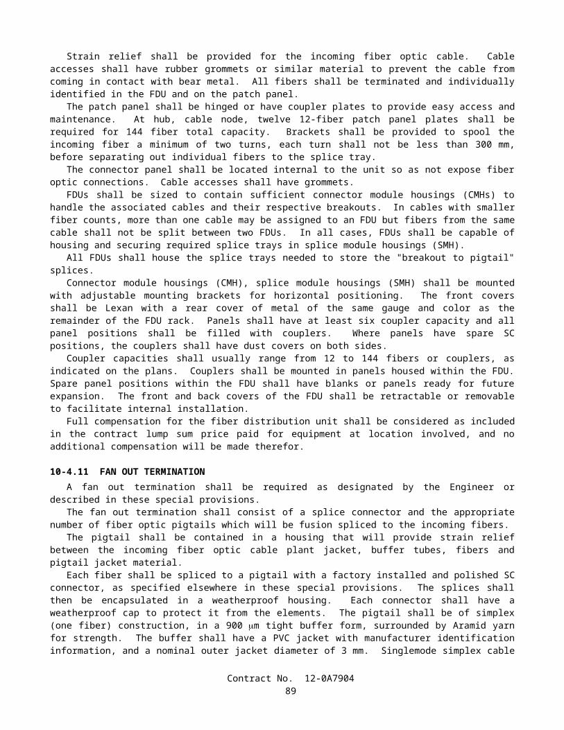
90-6.01 GENERAL Concrete shall be mixed in mechanically operated mixers, except that when permitted by the Engineer, batches not
exceeding 0.25 m3 may be mixed by hand methods in conformance with the provisions in Section 90-6.05, "Hand-Mixing." Equipment having components made of aluminum or magnesium alloys that would have contact with plastic
concrete during mixing, transporting, or pumping of portland cement concrete shall not be used. Concrete shall be homogeneous and thoroughly mixed, and there shall be no lumps or evidence of undispersed
cement, mineral admixture, or cement plus mineral admixture. Uniformity of concrete mixtures will be determined by differences in penetration as determined by California
Test 533, or slump as determined by ASTM Designation: C 143, and by variations in the proportion of coarse aggregate as determined by California Test 529.
When the mix design specifies a penetration value, the difference in penetration, determined by comparing penetration tests on 2 samples of mixed concrete from the same batch or truck mixer load, shall not exceed 10 mm. When the mix design specifies a slump value, the difference in slump, determined by comparing slump tests on 2 samples of mixed concrete from the same batch or truck mixer load, shall not exceed the values given in the table below. Variation in the proportion of coarse aggregate will be determined by comparing the results of tests of 2 samples of mixed concrete from the same batch or truck mixer load and the difference between the 2 results shall not exceed 100 kg per cubic meter of concrete.
Average Slump Maximum Permissible DifferenceLess than 100-mm 25-mm100-mm to 150-mm 38-mmGreater than 150-mm to 225-mm 50-mm
The Contractor, at the Contractor's expense, shall furnish samples of the freshly mixed concrete and provide satisfactory facilities for obtaining the samples.
90-6.02 MACHINE MIXING Concrete mixers may be of the revolving drum or the revolving blade type, and the mixing drum or blades shall be
operated uniformly at the mixing speed recommended by the manufacturer. Mixers and agitators that have an accumulation of hard concrete or mortar shall not be used.
The temperature of mixed concrete, immediately before placing, shall be not less than 10°C or more than 32°C. Aggregates and water shall be heated or cooled as necessary to produce concrete within these temperature limits. Neither aggregates nor mixing water shall be heated to exceed 65°C. If ice is used to cool the concrete, discharge of the mixer will not be permitted until all ice is melted.
The batch shall be so charged into the mixer that some water will enter in advance of cementitious materials and aggregates. All water shall be in the drum by the end of the first one - fourth of the specified mixing time.
Cementitious materials shall be batched and charged into the mixer by means that will not result either in loss of cementitious materials due to the effect of wind, in accumulation of cementitious materials on surfaces of conveyors or hoppers, or in other conditions that reduce or vary the required quantity of cementitious material in the concrete mixture.
Paving and stationary mixers shall be operated with an automatic timing device. The timing device and discharge mechanism shall be interlocked so that during normal operation no part of the batch will be discharged until the specified mixing time has elapsed.
The total elapsed time between the intermingling of damp aggregates and all cementitious materials and the start of mixing shall not exceed 30 minutes.
The size of batch shall not exceed the manufacturer's guaranteed capacity. When producing concrete for pavement or base, suitable batch counters shall be installed and maintained in good
operating condition at jobsite batching plants and stationary mixers. The batch counters shall indicate the exact number of batches proportioned and mixed.
Concrete shall be mixed and delivered to the jobsite by means of one of the following combinations of operations:
A. Mixed completely in a stationary mixer and the mixed concrete transported to the point of delivery in truck agitators or in non-agitating hauling equipment (central-mixed concrete).
B. Mixed partially in a stationary mixer, and the mixing completed in a truck mixer (shrink-mixed concrete).C. Mixed completely in a truck mixer (transit-mixed concrete).D. Mixed completely in a paving mixer.
Agitators may be truck mixers operating at agitating speed or truck agitators. Each mixer and agitator shall have attached thereto in a prominent place a metal plate or plates on which is plainly marked the various uses for which the
Contract No. 12-0A790489

equipment is designed, the manufacturer's guaranteed capacity of the drum or container in terms of the volume of mixed concrete and the speed of rotation of the mixing drum or blades.
Truck mixers shall be equipped with electrically or mechanically actuated revolution counters by which the number of revolutions of the drum or blades may readily be verified.
When shrink-mixed concrete is furnished, concrete that has been partially mixed at a central plant shall be transferred to a truck mixer and all requirements for transit-mixed concrete shall apply. No credit in the number of revolutions at mixing speed shall be allowed for partial mixing in a central plant.
90-6.03 TRANSPORTING MIXED CONCRETE Mixed concrete may be transported to the delivery point in truck agitators or truck mixers operating at the speed
designated by the manufacturer of the equipment as agitating speed, or in non-agitating hauling equipment, provided the consistency and workability of the mixed concrete upon discharge at the delivery point is suitable for adequate placement and consolidation in place, and provided the mixed concrete after hauling to the delivery point conforms to the provisions in Section 90-6.01, "General."
Truck agitators shall be loaded not to exceed the manufacturer's guaranteed capacity and shall maintain the mixed concrete in a thoroughly mixed and uniform mass during hauling.
Bodies of non-agitating hauling equipment shall be constructed so that leakage of the concrete mix, or any part thereof, will not occur at any time.
Concrete hauled in open-top vehicles shall be protected during hauling against rain or against exposure to the sun for more than 20 minutes when the ambient temperature exceeds 24°C.
No additional mixing water shall be incorporated into the concrete during hauling or after arrival at the delivery point, unless authorized by the Engineer. If the Engineer authorizes additional water to be incorporated into the concrete, the drum shall be revolved not less than 30 revolutions at mixing speed after the water is added and before discharge is commenced.
The rate of discharge of mixed concrete from truck mixer-agitators shall be controlled by the speed of rotation of the drum in the discharge direction with the discharge gate fully open.
When a truck mixer or agitator is used for transporting concrete to the delivery point, discharge shall be completed within 1.5 hours or before 250 revolutions of the drum or blades, whichever occurs first, after the introduction of the cement to the aggregates. Under conditions contributing to quick stiffening of the concrete, or when the temperature of the concrete is 30°C or above, the time allowed may be less than 1.5 hours.
When non-agitating hauling equipment is used for transporting concrete to the delivery point, discharge shall be completed within one hour after the addition of the cement to the aggregates. Under conditions contributing to quick stiffening of the concrete, or when the temperature of the concrete is 30°C or above, the time between the introduction of cement to the aggregates and discharge shall not exceed 45 minutes.
Each load of concrete delivered at the jobsite shall be accompanied by a weighmaster certificate showing the mix identification number, non-repeating load number, date and time at which the materials were batched, the total amount of water added to the load, and for transit-mixed concrete, the reading of the revolution counter at the time the truck mixer is charged with cement. This weighmaster certificate shall also show the actual scale masses (kilograms) for the ingredients batched. Theoretical or target batch masses shall not be used as a substitute for actual scale masses.
Weighmaster certificates shall be provided in printed form, or if approved by the Engineer, the data may be submitted in electronic media. Electronic media shall be presented in a tab-delimited format on a 90 mm diskette with a capacity of at least 1.4 megabytes. Captured data, for the ingredients represented by each batch shall be "line feed, carriage return" (LFCR) and "one line, separate record" with allowances for sufficient fields to satisfy the amount of data required by these specifications.
The Contractor may furnish a weighmaster certificate accompanied by a separate certificate that lists the actual batch masses or measurements for a load of concrete provided that both certificates are imprinted with the same non-repeating load number that is unique to the contract and delivered to the jobsite with the load.
Weighmaster certificates furnished by the Contractor shall conform to the provisions in Section 9-1.01, "Measurement of Quantities."
90-6.04 TIME OR AMOUNT OF MIXING Mixing of concrete in paving or stationary mixers shall continue for the required mixing time after all ingredients,
except water and admixture, if added with the water, are in the mixing compartment of the mixer before any part of the batch is released. Transfer time in multiple drum mixers shall not be counted as part of the required mixing time.
The required mixing time, in paving or stationary mixers, of concrete used for concrete structures, except minor structures, shall be not less than 90 seconds or more than 5 minutes, except that when directed by the Engineer in writing, the requirements of the following paragraph shall apply.
Contract No. 12-0A790490
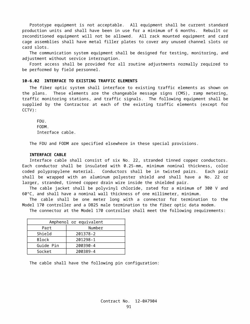
The required mixing time, in paving or stationary mixers, except as provided in the preceding paragraph, shall be not less than 50 seconds or more than 5 minutes.
The minimum required revolutions at the mixing speed for transit-mixed concrete shall not be less than that recommended by the mixer manufacturer, but in no case shall the number of revolutions be less than that required to consistently produce concrete conforming to the provisions for uniformity in Section 90-6.01, "General."
90-6.05 HAND-MIXING Hand-mixed concrete shall be made in batches of not more than 0.25 m3 and shall be mixed on a watertight, level
platform. The proper amount of coarse aggregate shall be measured in measuring boxes and spread on the platform and the fine aggregate shall be spread on this layer, the 2 layers being not more than 0.3 meters in total depth. On this mixture shall be spread the dry cement and mineral admixture and the whole mass turned no fewer than 2 times dry; then sufficient clean water shall be added, evenly distributed, and the whole mass again turned no fewer than 3 times, not including placing in the carriers or forms.
90-6.06 AMOUNT OF WATER AND PENETRATION The amount of water used in concrete mixes shall be regulated so that the penetration of the concrete as determined
by California Test 533 or the slump of the concrete as determined by ASTM Designation: C 143 is within the "Nominal" values shown in the following table. When the penetration or slump of the concrete is found to exceed the nominal values listed, the mixture of subsequent batches shall be adjusted to reduce the penetration or slump to a value within the nominal range shown. Batches of concrete with a penetration or slump exceeding the maximum values listed shall not be used in the work. When Type F or Type G chemical admixtures are added to the mix, the penetration requirements shall not apply and the slump shall not exceed 225 mm after the chemical admixtures are added.
Type of Work Nominal MaximumPenetration Slump Penetration Slump
(mm) (mm) (mm) (mm)Concrete Pavement 0-25 — 40 —Non-reinforced concrete facilities 0-35 — 50 —Reinforced concrete structures
Sections over 300-mm thick 0-35 — 65 —Sections 300-mm thick or less 0-50 — 75 —
Concrete placed under water — 150-200 — 225Cast-in-place concrete piles 65-90 130-180 100 200
The amount of free water used in concrete shall not exceed 183 kg/m3, plus 20 kg for each required 100 kg of cementitious material in excess of 325 kg/m3.
The term free water is defined as the total water in the mixture minus the water absorbed by the aggregates in reaching a saturated surface-dry condition.
Where there are adverse or difficult conditions that affect the placing of concrete, the above specified penetration and free water content limitations may be exceeded providing the Contractor is granted permission by the Engineer in writing to increase the cementitious material content per cubic meter of concrete. The increase in water and cementitious material shall be at a ratio not to exceed 30 kg of water per added 100 kg of cementitious material per cubic meter. The cost of additional cementitious material and water added under these conditions shall be at the Contractor’s expense and no additional compensation will be allowed therefor.
The equipment for supplying water to the mixer shall be constructed and arranged so that the amount of water added can be measured accurately. Any method of discharging water into the mixer for a batch shall be accurate within 1.5 percent of the quantity of water required to be added to the mix for any position of the mixer. Tanks used to measure water shall be designed so that water cannot enter while water is being discharged into the mixer and discharge into the mixer shall be made rapidly in one operation without dribbling. All equipment shall be arranged so as to permit checking the amount of water delivered by discharging into measured containers.
90-7 CURING CONCRETE
90-7.01 METHODS OF CURING Newly placed concrete shall be cured by the methods specified in this Section 90-7.01 and the special provisions.
Contract No. 12-0A790491
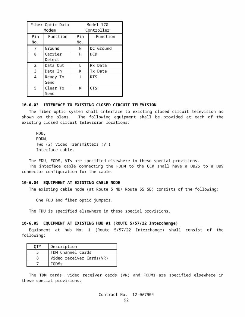
90-7.01A Water Method The concrete shall be kept continuously wet by the application of water for a minimum curing period of 7 days after
the concrete has been placed. When a curing medium consisting of cotton mats, rugs, carpets, or earth or sand blankets is to be used to retain the
moisture, the entire surface of the concrete shall be kept damp by applying water with a nozzle that so atomizes the flow that a mist and not a spray is formed, until the surface of the concrete is covered with the curing medium. The moisture from the nozzle shall not be applied under pressure directly upon the concrete and shall not be allowed to accumulate on the concrete in a quantity sufficient to cause a flow or wash the surface. At the expiration of the curing period, the concrete surfaces shall be cleared of all curing mediums.
When concrete bridge decks and flat slabs are to be cured without the use of a curing medium, the entire surface of the bridge deck or slab shall be kept damp by the application of water with an atomizing nozzle as specified in the preceding paragraph, until the concrete has set, after which the entire surface of the concrete shall be sprinkled continuously with water for a period of not less than 7 days.
90-7.01B Curing Compound Method Surfaces of the concrete that are exposed to the air shall be sprayed uniformly with a curing compound. Curing compounds to be used shall be as follows:
1. Pigmented curing compound conforming to the requirements in ASTM Designation: C 309, Type 2, Class B, except the resin type shall be poly-alpha-methylstyrene.
2. Pigmented curing compound conforming to the requirements in ASTM Designation: C 309, Type 2, Class B.3. Pigmented curing compound conforming to the requirements in ASTM Designation: C 309, Type 2, Class A.4. Non-pigmented curing compound conforming to the requirements in ASTM Designation: C 309, Type 1, Class B.5. Non-pigmented curing compound conforming to the requirements in ASTM Designation: C 309, Type 1, Class A.6. Non-pigmented curing compound with fugitive dye conforming to the requirements in ASTM Designation: C 309,
Type 1-D, Class A.
The infrared scan for the dried vehicle from curing compound (1) shall match the infrared scan on file at the Transportation Laboratory.
The loss of water for each type of curing compound, when tested in conformance with the requirements in California Test 534, shall not be more than 0.15-kg/m2 in 24 hours or more than 0.45-kg/m2 in 72 hours.
The curing compound to be used will be specified elsewhere in these specifications or in the special provisions. When the use of curing compound is required or permitted elsewhere in these specifications or in the special
provisions and no specific kind is specified, any of the curing compounds listed above may be used. Curing compound shall be applied at a nominal rate of 3.7 m2/L, unless otherwise specified. At any point, the application rate shall be within ±1.2 m2/L of the nominal rate specified, and the average application
rate shall be within ±0.5 m2/L of the nominal rate specified when tested in conformance with the requirements in California Test 535. Runs, sags, thin areas, skips, or holidays in the applied curing compound shall be evidence that the application is not satisfactory.
Curing compounds shall be applied using power operated spray equipment. The power operated spraying equipment shall be equipped with an operational pressure gage and a means of controlling the pressure. Hand spraying of small and irregular areas that are not reasonably accessible to mechanical spraying equipment, in the opinion of the Engineer, may be permitted.
The curing compound shall be applied to the concrete following the surface finishing operation, immediately before the moisture sheen disappears from the surface, but before any drying shrinkage or craze cracks begin to appear. In the event of any drying or cracking of the surface, application of water with an atomizing nozzle as specified in Section 90-7.01A, "Water Method," shall be started immediately and shall be continued until application of the compound is resumed or started; however, the compound shall not be applied over any resulting freestanding water. Should the film of compound be damaged from any cause before the expiration of 7 days after the concrete is placed in the case of structures and 72 hours in the case of pavement, the damaged portion shall be repaired immediately with additional compound.
At the time of use, compounds containing pigments shall be in a thoroughly mixed condition with the pigment uniformly dispersed throughout the vehicle. A paddle shall be used to loosen all settled pigment from the bottom of the container, and a power driven agitator shall be used to disperse the pigment uniformly throughout the vehicle.
Agitation shall not introduce air or other foreign substance into the curing compound. The manufacturer shall include in the curing compound the necessary additives for control of sagging, pigment
settling, leveling, de-emulsification, or other requisite qualities of a satisfactory working material. Pigmented curing compounds shall be manufactured so that the pigment does not settle badly, does not cake or thicken in the container, and does not become granular or curdled. Settlement of pigment shall be a thoroughly wetted, soft, mushy mass permitting the
Contract No. 12-0A790492

complete and easy vertical penetration of a paddle. Settled pigment shall be easily redispersed, with minimum resistance to the sideways manual motion of the paddle across the bottom of the container, to form a smooth uniform product of the proper consistency.
Curing compounds shall remain sprayable at temperatures above 4°C and shall not be diluted or altered after manufacture.
The curing compound shall be packaged in clean 210-L barrels or round 19-L containers or shall be supplied from a suitable storage tank located at the jobsite. The containers shall comply with "Title 49, Code of Federal Regulations, Hazardous Materials Regulations." The 210-L barrels shall have removable lids and airtight fasteners. The 19-L containers shall be round and have standard full open head and bail. Lids with bungholes shall not be permitted. On-site storage tanks shall be kept clean and free of contaminants. Each tank shall have a permanent system designed to completely redisperse settled material without introducing air or other foreign substances.
Steel containers and lids shall be lined with a coating that will prevent destructive action by the compound or chemical agents in the air space above the compound. The coating shall not come off the container or lid as skins. Containers shall be filled in a manner that will prevent skinning. Plastic containers shall not react with the compound.
Each container shall be labeled with the manufacturer's name, kind of curing compound, batch number, volume, date of manufacture, and volatile organic compound (VOC) content. The label shall also warn that the curing compound containing pigment shall be well stirred before use. Precautions concerning the handling and the application of curing compound shall be shown on the label of the curing compound containers in conformance with the Construction Safety Orders and General Industry Safety Orders of the State of California.
Containers of curing compound shall be labeled to indicate that the contents fully comply with the rules and regulations concerning air pollution control in the State of California.
When the curing compound is shipped in tanks or tank trucks, a shipping invoice shall accompany each load. The invoice shall contain the same information as that required herein for container labels.
Curing compound will be sampled by the Engineer at the source of supply or at the jobsite or at both locations. Curing compound shall be formulated so as to maintain the specified properties for a minimum of one year. The
Engineer may require additional testing before use to determine compliance with these specifications if the compound has not been used within one year or whenever the Engineer has reason to believe the compound is no longer satisfactory.
Tests will be conducted in conformance with the latest ASTM test methods and methods in use by the Transportation Laboratory.
90-7.01C Waterproof Membrane Method The exposed finished surfaces of concrete shall be sprayed with water, using a nozzle that so atomizes the flow that
a mist and not a spray is formed, until the concrete has set, after which the curing membrane shall be placed. The curing membrane shall remain in place for a period of not less than 72 hours.
Sheeting material for curing concrete shall conform to the requirements in AASHTO Designation: M 171 for white reflective materials.
The sheeting material shall be fabricated into sheets of such width as to provide a complete cover for the entire concrete surface. Joints in the sheets shall be securely cemented together in such a manner as to provide a waterproof joint. The joint seams shall have a minimum lap of 100 mm.
The sheets shall be securely weighted down by placing a bank of earth on the edges of the sheets or by other means satisfactory to the Engineer.
Should any portion of the sheets be broken or damaged before the expiration of 72 hours after being placed, the broken or damaged portions shall be immediately repaired with new sheets properly cemented into place.
Sections of membrane that have lost their waterproof qualities or have been damaged to such an extent as to render them unfit for curing the concrete shall not be used.
90-7.01D Forms-In-Place Method Formed surfaces of concrete may be cured by retaining the forms in place. The forms shall remain in place for a
minimum period of 7 days after the concrete has been placed, except that for members over 0.5-m in least dimension the forms shall remain in place for a minimum period of 5 days.
Joints in the forms and the joints between the end of forms and concrete shall be kept moisture tight during the curing period. Cracks in the forms and cracks between the forms and the concrete shall be resealed by methods subject to the approval of the Engineer.
90-7.02 CURING PAVEMENT The entire exposed area of the pavement, including edges, shall be cured by the waterproof membrane method, or
curing compound method using curing compound (1) or (2) as the Contractor may elect. Should the side forms be removed before the expiration of 72 hours following the start of curing, the exposed pavement edges shall also be cured. If the
Contract No. 12-0A790493

pavement is cured by means of the curing compound method, the sawcut and all portions of the curing compound that have been disturbed by sawing operations shall be restored by spraying with additional curing compound.
Curing shall commence as soon as the finishing process provided in Section 40-1.10, "Final Finishing," has been completed. The method selected shall conform to the provisions in Section 90-7.01, "Methods of Curing."
When the curing compound method is used, the compound shall be applied to the entire pavement surface by mechanical sprayers. Spraying equipment shall be of the fully atomizing type equipped with a tank agitator that provides for continual agitation of the curing compound during the time of application. The spray shall be adequately protected against wind, and the nozzles shall be so oriented or moved mechanically transversely as to result in the minimum specified rate of coverage being applied uniformly on exposed faces. Hand spraying of small and irregular areas, and areas inaccessible to mechanical spraying equipment, in the opinion of the Engineer, will be permitted. When the ambient air temperature is above 15°C, the Contractor shall fog the surface of the concrete with a fine spray of water as specified in Section 90 -7.01A, "Water Method." The surface of the pavement shall be kept moist between the hours of 10:00 a.m. and 4:30 p.m. on the day the concrete is placed. However, the fogging done after the curing compound has been applied shall not begin until the compound has set sufficiently to prevent displacement. Fogging shall be discontinued if ordered in writing by the Engineer.
90-7.03 CURING STRUCTURES Newly placed concrete for cast-in-place structures, other than highway bridge decks, shall be cured by the water
method, the forms-in-place method, or, as permitted herein, by the curing compound method, in conformance with the provisions in Section 90-7.01, "Methods of Curing."
The curing compound method using a pigmented curing compound may be used on concrete surfaces of construction joints, surfaces that are to be buried underground, and surfaces where only Ordinary Surface Finish is to be applied and on which a uniform color is not required and that will not be visible from a public traveled way. If the Contractor elects to use the curing compound method on the bottom slab of box girder spans, the curing compound shall be curing compound (1).
The top surface of highway bridge decks shall be cured by both the curing compound method and the water method. The curing compound shall be curing compound (1). The curing compound shall be applied progressively during the deck finishing operations immediately after finishing operations are completed on each individual portion of the deck. The water cure shall be applied not later than 4 hours after completion of deck finishing or, for portions of the decks on which finishing is completed after normal working hours, the water cure shall be applied not later than the following morning.
Concrete surfaces of minor structures, as defined in Section 51-1.02, "Minor Structures," shall be cured by the water method, the forms-in-place method or the curing compound method.
When deemed necessary by the Engineer during periods of hot weather, water shall be applied to concrete surfaces being cured by the curing compound method or by the forms-in-place method, until the Engineer determines that a cooling effect is no longer required. Application of water for this purpose will be paid for as extra work as provided in Section 4-1.03D, "Extra Work."
90-7.04 CURING PRECAST CONCRETE MEMBERS Precast concrete members shall be cured in conformance with any of the methods specified in Section 90-7.01,
"Methods of Curing." Curing shall be provided for the minimum time specified for each method or until the concrete reaches its design strength, whichever is less. Steam curing may also be used for precast members and shall conform to the following provisions:
A. After placement of the concrete, members shall be held for a minimum 4-hour presteaming period. If the ambient air temperature is below 10°C, steam shall be applied during the presteaming period to hold the air surrounding the member at a temperature between 10°C and 32°C.
B. To prevent moisture loss on exposed surfaces during the presteaming period, members shall be covered as soon as possible after casting or the exposed surfaces shall be kept wet by fog spray or wet blankets.
C. Enclosures for steam curing shall allow free circulation of steam about the member and shall be constructed to contain the live steam with a minimum moisture loss. The use of tarpaulins or similar flexible covers will be permitted, provided they are kept in good repair and secured in such a manner as to prevent the loss of steam and moisture.
D. Steam at the jets shall be at low pressure and in a saturated condition. Steam jets shall not impinge directly on the concrete, test cylinders, or forms. During application of the steam, the temperature rise within the enclosure shall not exceed 22°C per hour. The curing temperature throughout the enclosure shall not exceed 65°C and shall be maintained at a constant level for a sufficient time necessary to develop the required transfer strength. Control cylinders shall be covered to prevent moisture loss and shall be placed in a location where temperature is representative of the average temperature of the enclosure.
Contract No. 12-0A790494

E. Temperature recording devices that will provide an accurate, continuous, permanent record of the curing temperature shall be provided. A minimum of one temperature recording device per 60 m of continuous bed length will be required for checking temperature.
F. Members in pretension beds shall be detensioned immediately after the termination of steam curing while the concrete and forms are still warm, or the temperature under the enclosure shall be maintained above 15°C until the stress is transferred to the concrete.
G. Curing of precast concrete will be considered completed after termination of the steam curing cycle.
90-7.05 CURING PRECAST PRESTRESSED CONCRETE PILES Newly placed concrete for precast prestressed concrete piles shall be cured in conformance with the provisions in
Section 90-7.04, "Curing Precast Concrete Members," except that piles with a class designation ending in C (corrosion resistant) shall be cured as follows:
A. Piles shall be either steam cured or water cured. If water curing is used, the piles shall be kept continuously wet by the application of water in conformance with the provisions in Section 90-7.01A, "Water Method."
B. If steam curing is used, the steam curing provisions in Section 90-7.04, "Curing Precast Concrete Members," shall apply except that the piles shall be kept continuously wet for their entire length for a period of not less than 3 days, including the holding and steam curing periods.
90-7.06 CURING SLOPE PROTECTION Concrete slope protection shall be cured in conformance with any of the methods specified in Section 90-7.01,
"Methods of Curing." Concreted-rock slope protection shall be cured in conformance with any of the methods specified in Section
90-7.01, "Methods of Curing," or with a blanket of earth kept wet for 72 hours, or by sprinkling with a fine spray of water every 2 hours during the daytime for a period of 3 days.
90-7.07 CURING MISCELLANEOUS CONCRETE WORK Exposed surfaces of curbs shall be cured by pigmented curing compounds as specified in Section 90-7.01B, "Curing
Compound Method." Concrete sidewalks, gutter depressions, island paving, curb ramps, driveways, and other miscellaneous concrete
areas shall be cured in conformance with any of the methods specified in Section 90-7.01, "Methods of Curing." Shotcrete shall be cured for at least 72 hours by spraying with water, or by a moist earth blanket, or by any of the
methods provided in Section 90-7.01, "Methods of Curing." Mortar and grout shall be cured by keeping the surface damp for 3 days. After placing, the exposed surfaces of sign structure foundations, including pedestal portions, if constructed, shall be
cured for at least 72 hours by spraying with water, or by a moist earth blanket, or by any of the methods provided in Section 90-7.01, "Methods of Curing."
90-8 PROTECTING CONCRETE
90-8.01 GENERAL In addition to the provisions in Section 7-1.16, "Contractor's Responsibility for the Work and Materials," the
Contractor shall protect concrete as provided in this Section 90-8. Concrete shall not be placed on frozen or ice-coated ground or subgrade nor on ice-coated forms, reinforcing steel,
structural steel, conduits, precast members, or construction joints. Under rainy conditions, placing of concrete shall be stopped before the quantity of surface water is sufficient to
damage surface mortar or cause a flow or wash of the concrete surface, unless the Contractor provides adequate protection against damage.
Concrete that has been frozen or damaged by other causes, as determined by the Engineer, shall be removed and replaced by the Contractor at the Contractor's expense.
90-8.02 PROTECTING CONCRETE STRUCTURES Structure concrete and shotcrete used as structure concrete shall be maintained at a temperature of not less than 7°C
for 72 hours after placing and at not less than 4°C for an additional 4 days. When required by the Engineer, the Contractor shall submit a written outline of the proposed methods for protecting the concrete.
Contract No. 12-0A790495

90-8.03 PROTECTING CONCRETE PAVEMENT Pavement concrete shall be maintained at a temperature of not less than 4°C for 72 hours. When required by the
Engineer, the Contractor shall submit a written outline of the proposed methods for protecting the concrete. Except as provided in Section 7-1.08, "Public Convenience," the Contractor shall protect concrete pavement against
construction and other activities that abrade, scar, discolor, reduce texture depth, lower coefficient of friction, or otherwise damage the surface. Stockpiling, drifting, or excessive spillage of soil, gravel, petroleum products, and concrete or asphalt mixes on the surface of concrete pavement is prohibited unless otherwise specified in these specifications, the special provisions or permitted by the Engineer.
When ordered by the Engineer or shown on the plans or specified in the special provisions, pavement crossings shall be constructed for the convenience of public traffic. The material and work necessary for the construction of the crossings, and their subsequent removal and disposal, will be paid for at the contract unit prices for the items of work involved and if there are no contract items for the work involved, payment for pavement crossings will be made by extra work as provided in Section 4-1.03D, "Extra Work.". Where public traffic will be required to cross over the new pavement, Type III portland cement may be used in concrete, if permitted in writing by the Engineer. The pavement may be opened to traffic as soon as the concrete has developed a modulus of rupture of 3.8 MPa. The modulus of rupture will be determined by California Test 523.
No traffic or Contractor's equipment, except as hereinafter provided, will be permitted on the pavement before a period of 10 days has elapsed after the concrete has been placed, nor before the concrete has developed a modulus of rupture of at least 3.8 MPa. Concrete that fails to attain a modulus of rupture of 3.8 MPa within 10 days shall not be opened to traffic until directed by the Engineer.
Equipment for sawing weakened plane joints will be permitted on the pavement as specified in Section 40-1.08B, "Weakened Plane Joints."
When requested in writing by the Contractor, the tracks on one side of paving equipment will be permitted on the pavement after a modulus of rupture of 2.4 MPa has been attained, provided that:
A. Unit pressure exerted on the pavement by the paver shall not exceed 135 kPa;B. Tracks with cleats, grousers, or similar protuberances shall be modified or shall travel on planks or equivalent
protective material, so that the pavement is not damaged; andC. No part of the track shall be closer than 0.3-m from the edge of pavement.
In case of visible cracking of, or other damage to the pavement, operation of the paving equipment on the pavement shall be immediately discontinued.
Damage to the pavement resulting from early use of pavement by the Contractor's equipment as provided above shall be repaired by the Contractor at the Contractor's expense.
The State will furnish the molds and machines for testing the concrete for modulus of rupture, and the Contractor, at the Contractor's expense, shall furnish the material and whatever labor the Engineer may require.
90-9 COMPRESSIVE STRENGTH
90-9.01 GENERAL Concrete compressive strength requirements consist of a minimum strength that shall be attained before various
loads or stresses are applied to the concrete and, for concrete designated by strength, a minimum strength at the age of 28 days or at the age otherwise allowed in Section 90-1.01, "Description." The various strengths required are specified in these specifications or the special provisions or are shown on the plans.
The compressive strength of concrete will be determined from test cylinders that have been fabricated from concrete sampled in conformance with the requirements of ASTM Designation: C 172. Test cylinders will be molded and initially field cured in conformance with California Test 540. Test cylinders will be cured and tested after receipt at the testing laboratory in conformance with the requirements of ASTM Designation: C 39. A strength test shall consist of the average strength of 2 cylinders fabricated from material taken from a single load of concrete, except that, if any cylinder should show evidence of improper sampling, molding, or testing, that cylinder shall be discarded and the strength test shall consist of the strength of the remaining cylinder.
When concrete compressive strength is specified as a prerequisite to applying loads or stresses to a concrete structure or member, test cylinders for other than steam cured concrete will be cured in conformance with Method 1 of California Test 540. The compressive strength of concrete determined for these purposes will be evaluated on the basis of individual tests.
When concrete is designated by 28-day compressive strength rather than by cementitious material content, the concrete strength to be used as a basis for acceptance of other than steam cured concrete will be determined from cylinders cured in conformance with Method 1 of California Test 540. If the result of a single compressive strength test at the
Contract No. 12-0A790496

maximum age specified or allowed is below the specified strength but is 95 percent or more of the specified strength, the Contractor shall, at the Contractor’s expense, make corrective changes, subject to approval of the Engineer, in the mix proportions or in the concrete fabrication procedures, before placing additional concrete, and shall pay to the State $14 for each in-place cubic meter of concrete represented by the deficient test. If the result of a single compressive strength test at the maximum age specified or allowed is below 95 percent of the specified strength, but is 85 percent or more of the specified strength, the Contractor shall make the corrective changes specified above, and shall pay to the State $20 for each in place cubic meter of concrete represented by the deficient test. In addition, such corrective changes shall be made when the compressive strength of concrete tested at 7 days indicates, in the judgment of the Engineer, that the concrete will not attain the required compressive strength at the maximum age specified or allowed. Concrete represented by a single test that indicates a compressive strength of less than 85 percent of the specified 28-day compressive strength will be rejected in conformance with the provisions in Section 6-1.04, "Defective Materials."
If the test result indicates that the compressive strength at the maximum curing age specified or allowed is below the specified strength, but is 85 percent or more of the specified strength, payments to the State as required above shall be made, unless the Contractor, at the Contractor’s expense, obtains and submits evidence acceptable to the Engineer that the strength of the concrete placed in the work meets or exceeds the specified 28-day compressive strength. If the test result indicates a compressive strength at the maximum curing age specified or allowed below 85 percent, the concrete represented by that test will be rejected, unless the Contractor, at the Contractor’s expense, obtains and submits evidence acceptable to the Engineer that the strength and quality of the concrete placed in the work are acceptable. If the evidence consists of tests made on cores taken from the work, the cores shall be obtained and tested in conformance with the requirements in ASTM Designation: C 42.
No single compressive strength test shall represent more than 250 m3. When a precast concrete member is steam cured, the compressive strength of the concrete will be determined from
test cylinders that have been handled and stored in conformance with Method 3 of California Test 540. The compressive strength of steam cured concrete will be evaluated on the basis of individual tests representing specific portions of production. When the concrete is designated by 28-day compressive strength rather than by cementitious material content, the concrete shall be considered to be acceptable whenever its compressive strength reaches the specified 28-day compressive strength provided that strength is reached in not more than the maximum number of days specified or allowed after the member is cast.
When concrete is specified by compressive strength, prequalification of materials, mix proportions, mixing equipment, and procedures proposed for use will be required prior to placement of the concrete. Prequalification shall be accomplished by the submission of acceptable certified test data or trial batch reports by the Contractor. Prequalification data shall be based on the use of materials, mix proportions, mixing equipment, procedures, and size of batch proposed for use in the work.
Certified test data, in order to be acceptable, shall indicate that not less than 90 percent of at least 20 consecutive tests exceed the specified strength at the maximum number of cure days specified or allowed, and none of those tests are less than 95 percent of specified strength. Strength tests included in the data shall be the most recent tests made on concrete of the proposed mix design and all shall have been made within one year of the proposed use of the concrete.
Trial batch test reports, in order to be acceptable, shall indicate that the average compressive strength of 5 consecutive concrete cylinders, taken from a single batch, at not more than 28 days (or the maximum age allowed) after molding shall be at least 4 MPa greater than the specified 28-day compressive strength, and no individual cylinder shall have a strength less than the specified strength at the maximum age specified or allowed. Data contained in the report shall be from trial batches that were produced within one year of the proposed use of specified strength concrete in the project. Whenever air-entrainment is required, the air content of trial batches shall be equal to or greater than the air content specified for the concrete without reduction due to tolerances.
Tests shall be performed in conformance with either the appropriate California Test methods or the comparable ASTM test methods. Equipment employed in testing shall be in good condition and shall be properly calibrated. If the tests are performed during the life of the contract, the Engineer shall be notified sufficiently in advance of performing the tests in order to witness the test procedures.
The certified test data and trial batch test reports shall include the following information:
A. Date of mixing.B. Mixing equipment and procedures used.C. The size of batch in cubic meters and the mass, type, and source of all ingredients used.D. Penetration of the concrete.E. The air content of the concrete if an air-entraining admixture is used.F. The age at time of testing and strength of all concrete cylinders tested.
Certified test data and trial batch test reports shall be signed by an official of the firm that performed the tests.
Contract No. 12-0A790497

When approved by the Engineer, concrete from trial batches may be used in the work at locations where concrete of a lower quality is required and the concrete will be paid for as the type or class of concrete required at that location.
After materials, mix proportions, mixing equipment, and procedures for concrete have been prequalified for use, additional prequalification by testing of trial batches will be required prior to making changes that, in the judgment of the Engineer, could result in a strength of concrete below that specified.
The Contractor’s attention is directed to the time required to test trial batches and the Contractor shall be responsible for production of trial batches at a sufficiently early date so that the progress of the work is not delayed.
When precast concrete members are manufactured at the plant of an established manufacturer of precast concrete members, the mix proportions of the concrete shall be determined by the Contractor, and a trial batch and prequalification of the materials, mix proportions, mixing equipment, and procedures will not be required.
90-10 MINOR CONCRETE
90-10.01 GENERAL Concrete for minor structures, slope paving, curbs, sidewalks and other concrete work, when designated as minor
concrete on the plans, in the specifications, or in the contract item, shall conform to the provisions specified herein. The Engineer, at the Engineer's discretion, will inspect and test the facilities, materials and methods for producing
the concrete to ensure that minor concrete of the quality suitable for use in the work is obtained.
90-10.02 MATERIALS Minor concrete shall conform to the following requirements:
90-10.02A Cementitious Material Cementitious material shall conform to the provisions in Section 90-1.01, "Description."
90-10.02B Aggregate Aggregate shall be clean and free from deleterious coatings, clay balls, roots, and other extraneous materials. The Contractor shall submit to the Engineer for approval, a grading of the combined aggregate proposed for use in
the minor concrete. After acceptance of the grading, aggregate furnished for minor concrete shall conform to that grading, unless a change is authorized in writing by the Engineer.
The Engineer may require the Contractor to furnish periodic test reports of the aggregate grading furnished. The maximum size of aggregate used shall be at the option of the Contractor, but in no case shall the maximum size be larger than 37.5 mm or smaller than 19 mm.
The Engineer may waive, in writing, the gradation requirements in this Section 90-10.02B, if, in the Engineer's opinion, the furnishing of the gradation is not necessary for the type or amount of concrete work to be constructed.
90-10.02C Water Water used for washing, mixing, and curing shall be free from oil, salts, and other impurities that would discolor or
etch the surface or have an adverse affect on the quality of the concrete.
90-10.02D Admixtures The use of admixtures shall conform to the provisions in Section 90-4, "Admixtures."
90-10.03 PRODUCTION Cementitious material, water, aggregate, and admixtures shall be stored, proportioned, mixed, transported, and
discharged in conformance with recognized standards of good practice that will result in concrete that is thoroughly and uniformly mixed, that is suitable for the use intended, and that conforms to requirements specified herein. Recognized standards of good practice are outlined in various industry publications such as are issued by American Concrete Institute, AASHTO, or the Department.
The cementitious material content of minor concrete shall conform to the provisions in Section 90-1.01, "Description."
The amount of water used shall result in a consistency of concrete conforming to the provisions in Section 90 -6.06, "Amount of Water and Penetration." Additional mixing water shall not be incorporated into the concrete during hauling or after arrival at the delivery point, unless authorized by the Engineer.
Discharge of ready-mixed concrete from the transporting vehicle shall be made while the concrete is still plastic and before stiffening occurs. An elapsed time of 1.5 hours (one hour in non-agitating hauling equipment), or more than
Contract No. 12-0A790498

250 revolutions of the drum or blades, after the introduction of the cementitious material to the aggregates, or a temperature of concrete of more than 32°C will be considered conditions contributing to the quick stiffening of concrete. The Contractor shall take whatever action is necessary to eliminate quick stiffening, except that the addition of water will not be permitted.
The required mixing time in stationary mixers shall be not less than 50 seconds or more than 5 minutes. The minimum required revolutions at mixing speed for transit-mixed concrete shall be not less than that
recommended by the mixer manufacturer, and shall be increased, if necessary, to produce thoroughly and uniformly mixed concrete.
Each load of ready-mixed concrete shall be accompanied by a weighmaster certificate that shall be delivered to the Engineer at the discharge location of the concrete, unless otherwise directed by the Engineer. The weighmaster certificate shall be clearly marked with the date and time of day when the load left the batching plant and, if hauled in truck mixers or agitators, the time the mixing cycle started.
A Certificate of Compliance conforming to the provisions in Section 6–1.07, "Certificates of Compliance," shall be furnished to the Engineer, prior to placing minor concrete from a source not previously used on the contract, stating that minor concrete to be furnished meets contract requirements, including minimum cementitious material content specified.
90-10.04 CURING MINOR CONCRETE Curing minor concrete shall conform to the provisions in Section 90-7, "Curing Concrete."
90-10.05 PROTECTING MINOR CONCRETE Protecting minor concrete shall conform to the provisions in Section 90-8, "Protecting Concrete," except the
concrete shall be maintained at a temperature of not less than 4°C for 72 hours after placing.
90-10.06 MEASUREMENT AND PAYMENT Minor concrete will be measured and paid for in conformance with the provisions specified in the various sections
of these specifications covering concrete construction when minor concrete is specified in the specifications, shown on the plans, or indicated by contract item in the Engineer's Estimate.
90-11 MEASUREMENT AND PAYMENT
90-11.01 MEASUREMENT Portland cement concrete will be measured in conformance with the provisions specified in the various sections of
these specifications covering construction requiring concrete. When it is provided that concrete will be measured at the mixer, the volume in cubic meters shall be computed as
the total mass of the batch in kilograms divided by the density of the concrete in kilograms per cubic meter. The total mass of the batch shall be calculated as the sum of all materials, including water, entering the batch. The density of the concrete will be determined in conformance with the requirements in California Test 518.
90-11.02 PAYMENT Portland cement concrete will be paid for in conformance with the provisions specified in the various sections of
these specifications covering construction requiring concrete. Full compensation for furnishing and incorporating admixtures required by these specifications or the special
provisions will be considered as included in the contract prices paid for the concrete involved and no additional compensation will be allowed therefor.
Should the Engineer order the Contractor to incorporate any admixtures in the concrete when their use is not required by these specifications or the special provisions, furnishing the admixtures and adding them to the concrete will be paid for as extra work as provided in Section 4-1.03D, "Extra Work."
Should the Contractor use admixtures in conformance with the provisions in Section 90-4.05, "Optional Use of Chemical Admixtures," or Section 90-4.07, "Optional Use of Air-entraining Admixtures," or should the Contractor request and obtain permission to use other admixtures for the Contractor’s benefit, the Contractor shall furnish those admixtures and incorporate them into the concrete at the Contractor’s expense and no additional compensation will be allowed therefor.
Contract No. 12-0A790499