99SSP_Template - Caltrans - California Department of ... · Web view2 1.06 CALIFORNIA COMPANY...
131
** WARNING ** WARNING ** WARNING ** WARNING ** This document is intended for informational purposes only. Users are cautioned that California Department of Transportation (Department) does not assume any liability or responsibility based on these electronic files or for any defective or incomplete copying, exerpting, scanning, faxing or downloading of the contract documents. As always, for the official paper versions of the bidders packages and non-bidder packages, including addenda write to the California Department of Transportation, Plans and Bid Documents, Room 0200, P.O. Box 942874, Sacramento, CA 94272-0001, telephone (916) 654-4490 or fax (916) 654-7028. Office hours are 7:30 a.m. to 4:15 p.m. When ordering bidder or non-bidder packages it is important that you include a telephone number and fax number, P.O. Box and street address so that you can receive addenda. etric Caltrans STATE OF CALIFORNIA DEPARTMENT OF TRANSPORTATION __________________________________________________________ NOTICE TO CONTRACTORS AND SPECIAL PROVISIONS FOR HIGHWAY PLANTING ON STATE HIGHWAY IN SAN DIEGO COUNTY IN SAN DIEGO FROM RANCHO PENASQUITOS BOULEVARD UNDERCROSSING TO 0.3 km WEST OF ROUTE 56/15 SEPARATION DISTRICT 11, ROUTE 56 __________________________________________________________ For Use in Connection with Standard Specifications Dated JULY 1999, Standard Plans Dated JULY 1999, and Labor Surcharge and Equipment Rental Rates. __________________________________________________________
Transcript of 99SSP_Template - Caltrans - California Department of ... · Web view2 1.06 CALIFORNIA COMPANY...

** WARNING ** WARNING ** WARNING ** WARNING **This document is intended for informational purposes only.
Users are cautioned that California Department of Transportation (Department) does not assume any liability or responsibility based on these electronic files or for any defective or incomplete copying, exerpting, scanning, faxing or downloading of the contract documents. As always, for the official paper versions of the bidders packages and non-bidder packages, including addenda write to the California Department of Transportation, Plans and Bid Documents, Room 0200, P.O. Box 942874, Sacramento, CA 94272-0001, telephone (916) 654-4490 or fax (916) 654-7028. Office hours are 7:30 a.m. to 4:15 p.m. When ordering bidder or non-bidder packages it is important that you include a telephone number and fax number, P.O. Box and street address so that you can receive addenda.
etric
Caltrans
STATE OF CALIFORNIA
DEPARTMENT OF TRANSPORTATION__________________________________________________________
NOTICE TO CONTRACTORSAND
SPECIAL PROVISIONSFOR HIGHWAY PLANTING ON STATE HIGHWAY IN SAN DIEGO COUNTY IN SAN DIEGO FROM RANCHO PENASQUITOS BOULEVARD
UNDERCROSSING TO 0.3 km WEST OF ROUTE 56/15 SEPARATION
DISTRICT 11, ROUTE 56
__________________________________________________________
For Use in Connection with Standard Specifications Dated JULY 1999, Standard Plans Dated JULY 1999, and Labor Surcharge and Equipment Rental Rates.
__________________________________________________________
CONTRACT NO. 11-247604
11-SD-56-12.9/14.5
Bids Open: October 25, 2001Dated: September 24, 2001

*************************************************************************************************
IMPORTANTSPECIAL NOTICES
*************************************************************************************************
Payment BondsAttention is directed to Section 5 of the Special Provisions, regarding contract bonds. The payment bond shall be in a sum not less than one hundred percent of the total amount payable by the terms of the contract.
Attention is directed to "Miscellaneous Metal," in Section 8-1, "Miscellaneous," of these Special Provisions for new requirements for miscellaneous metal.
TABLE OF CONTENTS
NOTICE TO CONTRACTORS.............................................................................................................................................1COPY OF ENGINEER'S ESTIMATE..................................................................................................................................3SPECIAL PROVISIONS.......................................................................................................................................................6SECTION 1. SPECIFICATIONS AND PLANS..................................................................................................................6SECTION 2. PROPOSAL REQUIREMENTS AND CONDITIONS..................................................................................6
2-1.01 GENERAL..........................................................................................................................................................62-1.02 DISABLED VETERAN BUSINESS ENTERPRISE (DVBE)..........................................................................62-1.03 DVBE GOAL FOR THIS PROJECT.................................................................................................................72-1.04 SUBMISSION OF DVBE INFORMATION.....................................................................................................72-1.05 SMALL BUSINESS PREFERENCE.................................................................................................................82-1.06 CALIFORNIA COMPANY PREFERENCE.....................................................................................................9
SECTION 3. AWARD AND EXECUTION OF CONTRACT............................................................................................9SECTION 4. BEGINNING OF WORK, TIME OF COMPLETION AND LIQUIDATED DAMAGES.........................10SECTION 5. GENERAL....................................................................................................................................................10SECTION 5-1. MISCELLANEOUS..................................................................................................................................10
5-1.01 PLANS AND WORKING DRAWINGS.........................................................................................................105-1.011 EXAMINATION OF PLANS, SPECIFICATIONS, CONTRACT, AND SITE OF WORK.......................105-1.012 DIFFERING SITE CONDITIONS.................................................................................................................105-1.015 LABORATORY.............................................................................................................................................115-1.017 CONTRACT BONDS....................................................................................................................................115-1.018 EXCAVATION SAFETY PLANS................................................................................................................115-1.019 COST REDUCTION INCENTIVE................................................................................................................125-1.02 LABOR NONDISCRIMINATION..................................................................................................................125-1.03 INTEREST ON PAYMENTS..........................................................................................................................125-1.031 FINAL PAYMENT AND CLAIMS..............................................................................................................125-1.04 PUBLIC SAFETY............................................................................................................................................135-1.05 SURFACE MINING AND RECLAMATION ACT........................................................................................145-1.06 REMOVAL OF ASBESTOS AND HAZARDOUS SUBSTANCES..............................................................145-1.07 YEAR 2000 COMPLIANCE...........................................................................................................................145-1.08 SUBCONTRACTOR AND DVBE RECORDS..............................................................................................145-1.086 PERFORMANCE OF DVBE SUBCONTRACTORS AND SUPPLIERS...................................................145-1.09 SUBCONTRACTING......................................................................................................................................155-1.10 PROMPT PROGRESS PAYMENT TO SUBCONTRACTORS....................................................................155-1.11 ENVIRONMENTALLY SENSITIVE AREA (ESA)......................................................................................155-1.12 AREAS FOR CONTRACTOR'S USE.............................................................................................................155-1.13 PAYMENTS.....................................................................................................................................................165-1.14 SOUND CONTROL REQUIREMENTS.........................................................................................................16
SECTION 6. (BLANK).......................................................................................................................................................17SECTION 7. (BLANK).......................................................................................................................................................17SECTION 8. MATERIALS................................................................................................................................................17SECTION 8-1. MISCELLANEOUS..................................................................................................................................17
8-1.01 SUBSTITUTION OF NON-METRIC MATERIALS AND PRODUCTS......................................................178-1.02 PREQUALIFIED AND TESTED SIGNING AND DELINEATION MATERIALS.....................................238-1.03 STATE-FURNISHED MATERIALS..............................................................................................................288-1.04 SLAG AGGREGATE......................................................................................................................................28
SECTION 8-2. CONCRETE...............................................................................................................................................288-2.01 PORTLAND CEMENT CONCRETE.............................................................................................................288-2.02 CEMENT AND WATER CONTENT.............................................................................................................29
SECTION 8-3. (BLANK)...................................................................................................................................................30SECTION 9. (BLANK).......................................................................................................................................................30SECTION 10. CONSTRUCTION DETAILS....................................................................................................................30SECTION 10-1. GENERAL...............................................................................................................................................30
10-1.01 ORDER OF WORK.......................................................................................................................................3010-1.02 WATER POLLUTION CONTROL...............................................................................................................30
Contract No. 11-2476041

WATER POLLUTION CONTROL PROGRAM PREPARATION, APPROVAL AND UPDATES.................31WPCP IMPLEMENTATION................................................................................................................................32MAINTENANCE..................................................................................................................................................33WATER POLLUTION CONTROL TRAINING..................................................................................................33PAYMENT............................................................................................................................................................33
10-1.03 PRESERVATION OF PROPERTY...............................................................................................................3310-1.04 TEMPORARY GRAVEL BAG.....................................................................................................................34
MATERIALS.........................................................................................................................................................34INSTALLATION..................................................................................................................................................34MEASUREMENT AND PAYMENT...................................................................................................................34
10-1.05 TEMPORARY CONCRETE WASHOUT.....................................................................................................3410-1.06 COOPERATION............................................................................................................................................3510-1.07 PROGRESS SCHEDULE..............................................................................................................................3510-1.08 OBSTRUCTIONS..........................................................................................................................................3510-1.09 MOBILIZATION...........................................................................................................................................3610-1.10 CONSTRUCTION AREA TRAFFIC CONTROL DEVICES......................................................................3610-1.11 CONSTRUCTION AREA SIGNS.................................................................................................................3610-1.12 MAINTAINING TRAFFIC............................................................................................................................3710-1.13 CLOSURE REQUIREMENTS AND CONDITIONS...................................................................................40
CLOSURE SCHEDULE.......................................................................................................................................40CONTINGENCY PLAN.......................................................................................................................................40LATE REOPENING OF CLOSURES..................................................................................................................40COMPENSATION................................................................................................................................................40
10-1.14 CONSTRUCTION ZONE ENHANCED ENFORCEMENT........................................................................4010-1.15 TRAFFIC CONTROL SYSTEM FOR LANE CLOSURE............................................................................4110-1.16 TEMPORARY PAVEMENT DELINEATION.............................................................................................42
GENERAL.............................................................................................................................................................42TEMPORARY LANELINE AND CENTERLINE DELINEATION...................................................................42
10-1.17 TRAFFIC PLASTIC DRUMS.......................................................................................................................4210-1.18 TEMPORARY CRASH CUSHION MODULE............................................................................................4310-1.19 DECOMPOSED GRANITE...........................................................................................................................4410-1.20 FIBER ROLLS...............................................................................................................................................45
MATERIALS.........................................................................................................................................................45INSTALLATION..................................................................................................................................................45MEASUREMENT AND PAYMENT...................................................................................................................45
10-1.21 MAINTENANCE VEHICLE PULLOUT......................................................................................................45EARTHWORK......................................................................................................................................................45AGGREGATE BASE............................................................................................................................................45ASPHALT CONCRETE.......................................................................................................................................46MEASUREMENT.................................................................................................................................................46PAYMENT............................................................................................................................................................46
10-1.22 SLOPE PAVING............................................................................................................................................4610-1.23 CHAIN LINK WALK GATE........................................................................................................................46
SECTION 10-2. HIGHWAY PLANTING AND IRRIGATION SYSTEMS....................................................................4710-2.01 GENERAL......................................................................................................................................................4710-2.02 EXISTING HIGHWAY PLANTING............................................................................................................47
MAINTAIN EXISTING PLANTED AREAS......................................................................................................4710-2.03 EXISTING HIGHWAY IRRIGATION FACILITIES...................................................................................48
LOCATE EXISTING CROSSOVERS AND CONDUITS...................................................................................48CHECK AND TEST EXISTING IRRIGATION FACILITIES............................................................................48REMOVE EXISTING IRRIGATION FACILITIES.............................................................................................48
10-2.04 HIGHWAY PLANTING................................................................................................................................49HIGHWAY PLANTING MATERIALS...............................................................................................................49ROADSIDE CLEARING......................................................................................................................................49PESTICIDES.........................................................................................................................................................50PREPARING PLANTING AREAS......................................................................................................................51PREPARE HOLES................................................................................................................................................51WEED GERMINATION.......................................................................................................................................51
Contract No. 11-2476042

PLANTING............................................................................................................................................................51PLANT ESTABLISHMENT WORK....................................................................................................................51
10-2.05 IRRIGATION SYSTEMS..............................................................................................................................52VALVE BOXES....................................................................................................................................................52ELECTRIC AUTOMATIC IRRIGATION COMPONENTS...............................................................................52REMOTE CONTROL VALVE (MASTER) WITH FLOW METER..................................................................54IRRIGATION SYSTEMS FUNCTIONAL TEST................................................................................................55IRRIGATION CROSSOVERS (OPEN TRENCH)..............................................................................................55PIPE.......................................................................................................................................................................56FERTILIZER COUPLING....................................................................................................................................56SPRINKLERS........................................................................................................................................................57FINAL IRRIGATION SYSTEM CHECK............................................................................................................57
SECTION 10-3. ELECTRICAL SYSTEMS......................................................................................................................5710-3.01 DESCRIPTION..............................................................................................................................................5710-3.02 COST BREAK-DOWN..................................................................................................................................5710-3.03 CONDUIT......................................................................................................................................................5710-3.04 PULL BOXES................................................................................................................................................5810-3.05 CONDUCTORS AND WIRING....................................................................................................................5810-3.06 SERVICE........................................................................................................................................................58
ELECTRIC SERVICE (IRRIGATION)................................................................................................................5810-3.07 IRRIGATION CONTROLLER ENCLOSURE CABINET...........................................................................5810-3.08 PAYMENT.....................................................................................................................................................59
SECTION 11. MODIFIED STANDARD SPECIFICATION SECTIONS........................................................................59SECTION 11-1. (BLANK).................................................................................................................................................59SECTION 11-2. PORTLAND CEMENT CONCRETE.....................................................................................................59
Contract No. 11-2476043
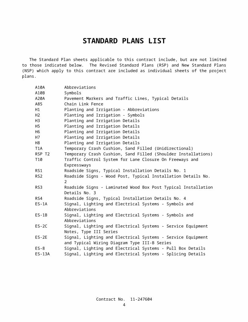
STANDARD PLANS LIST
The Standard Plan sheets applicable to this contract include, but are not limited to those indicated below. The Revised Standard Plans (RSP) and New Standard Plans (NSP) which apply to this contract are included as individual sheets of the project plans.
A10A AbbreviationsA10B SymbolsA20A Pavement Markers and Traffic Lines, Typical DetailsA85 Chain Link FenceH1 Planting and Irrigation - AbbreviationsH2 Planting and Irrigation - SymbolsH3 Planting and Irrigation DetailsH5 Planting and Irrigation DetailsH6 Planting and Irrigation DetailsH7 Planting and Irrigation DetailsH8 Planting and Irrigation DetailsT1A Temporary Crash Cushion, Sand Filled (Unidirectional)RSP T2 Temporary Crash Cushion, Sand Filled (Shoulder Installations)T10 Traffic Control System for Lane Closure On Freeways and ExpresswaysRS1 Roadside Signs, Typical Installation Details No. 1RS2 Roadside Signs - Wood Post, Typical Installation Details No. 2RS3 Roadside Signs - Laminated Wood Box Post Typical Installation Details No. 3RS4 Roadside Signs, Typical Installation Details No. 4ES-1A Signal, Lighting and Electrical Systems - Symbols and AbbreviationsES-1B Signal, Lighting and Electrical Systems - Symbols and AbbreviationsES-2C Signal, Lighting and Electrical Systems - Service Equipment Notes, Type III SeriesES-2E Signal, Lighting and Electrical Systems - Service Equipment and Typical Wiring Diagram
Type III-B SeriesES-8 Signal, Lighting and Electrical Systems - Pull Box DetailsES-13A Signal, Lighting and Electrical Systems - Splicing Details
Contract No. 11-2476044
State Project with DVBE Goals (06-14-00)
DEPARTMENT OF TRANSPORTATION_________________________
NOTICE TO CONTRACTORS
_________________________
CONTRACT NO. 11-247604
11-SD-56-12.9/14.5
Sealed proposals for the work shown on the plans entitled:
STATE OF CALIFORNIA; DEPARTMENT OF TRANSPORTATION; PROJECT PLANS FOR HIGHWAY PLANTING ON STATE HIGHWAY IN SAN DIEGO COUNTY IN SAN DIEGO FROM RANCHO PENASQUITOS
BOULEVARD UNDERCROSSING TO 0.3 km WEST OF ROUTE 56/15 SEPARATION
will be received at the Department of Transportation, 3347 Michelson Drive, Suite 100, Irvine, CA 92612-1692, until 2 o'clock p.m. on October 25, 2001, at which time they will be publicly opened and read in Room C - 1116 at the same address.
Proposal forms for this work are included in a separate book entitled:
STATE OF CALIFORNIA; DEPARTMENT OF TRANSPORTATION; PROPOSAL AND CONTRACT FOR HIGHWAY PLANTING ON STATE HIGHWAY IN SAN DIEGO COUNTY IN SAN DIEGO FROM RANCHO
PENASQUITOS BOULEVARD UNDERCROSSING TO 0.3 km WEST OF ROUTE 56/15 SEPARATION
General work description: This project is to restore existing Highway Planting.
This project has a goal of 3 percent disabled veteran business enterprise (DVBE) participation.No prebid meeting is scheduled for this project.Bids are required for the entire work described herein.At the time this contract is awarded, the Contractor shall possess either a Class A license or one of the following Class C
licenses: C-12, C-27.The Contractor must also be properly licensed at the time the bid is submitted, except that on a joint venture bid a joint
venture license may be obtained by a combination of licenses after bid opening but before award in conformance with Business and Professions Code, Section 7029.1.
This contract is subject to state contract nondiscrimination and compliance requirements pursuant to Government Code, Section 12990.
Preference will be granted to bidders properly certified as a "Small Business" as determined by the Department of General Services, Office of Small Business Certification and Resources at the time of bid opening in conformance with the provisions in Section 2-1.05, "Small Business Preference," of the special provisions, and Section 1896 et seq, Title 2, California Code of Regulations. A form for requesting a "Small Business" preference is included with the bid documents. Applications for status as a "Small Business" must be submitted to the Department of General Services, Office of Small Business Certification and Resources, 1531 "I" Street, Second Floor, Sacramento, CA 95814, Telephone No. (916) 322-5060.
A reciprocal preference will be granted to "California company" bidders in conformance with Section 6107 of the Public Contract Code. (See Sections 2 and 3 of the special provisions.) A form for indicating whether bidders are or are not a "California company" is included in the bid documents and is to be filled in and signed by all bidders.
Contract No. 11-2476041
The Caltrans District 11 Office is located at 2829 Juan Street, San Diego, CA 92110. The mailing address is P.O. Box 85406, San Diego, CA 92186-5406, E-mail address of the Duty Senior is: [email protected], or by fax at (619) 688-6988. The District 11 Duty Senior telephone number is (619) 688-6635.
The Website address for posting of questions and responses is: www.dot.ca.gov/dist11/construc/Project plans, special provisions, and proposal forms for bidding this project can only be obtained at the Department of
Transportation, Plans and Bid Documents, Room 0200, MS #26, Transportation Building, 1120 N Street, Sacramento, California 95814, FAX No. (916) 654-7028, Telephone No. (916) 654-4490. Use FAX orders to expedite orders for project plans, special provisions and proposal forms. FAX orders must include credit card charge number, card expiration date and authorizing signature. Project plans, special provisions, and proposal forms may be seen at the above Department of Transportation office and at the offices of the District Directors of Transportation at Irvine, Oakland, and the district in which the work is situated. Standard Specifications and Standard Plans are available through the State of California, Department of Transportation, Publications Unit, 1900 Royal Oaks Drive, Sacramento, CA 95815, Telephone No. (916) 445-3520.
Cross sections for this project are not available.The successful bidder shall furnish a payment bond and a performance bond.
Pursuant to Section 1773 of the Labor Code, the general prevailing wage rates in the county, or counties, in which the work is to be done have been determined by the Director of the California Department of Industrial Relations. These wages are set forth in the General Prevailing Wage Rates for this project, available at the Labor Compliance Office at the offices of the District Director of Transportation for the district in which the work is situated, and available from the California Department of Industrial Relations’ Internet Web Site at: http://www.dir.ca.gov. Future effective general prevailing wage rates which have been predetermined and are on file with the Department of Industrial Relations are referenced but not printed in the general prevailing wage rates.
DEPARTMENT OF TRANSPORTATION
Deputy Director Transportation Engineering
Dated September 24, 2001
D11CS
Contract No. 11-2476042
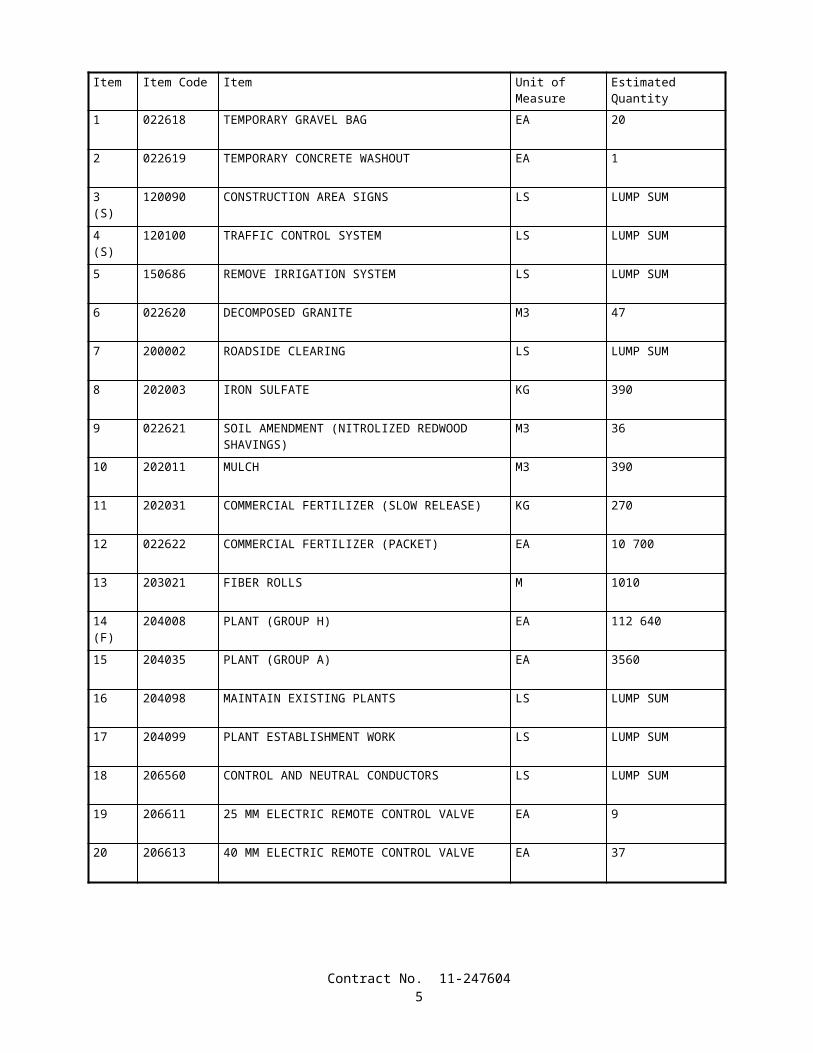
COPY OF ENGINEER'S ESTIMATE
(NOT TO BE USED FOR BIDDING PURPOSES)
11-247604
Item Item Code Item Unit of Measure Estimated Quantity
1 022618 TEMPORARY GRAVEL BAG EA 20
2 022619 TEMPORARY CONCRETE WASHOUT EA 1
3(S)
120090 CONSTRUCTION AREA SIGNS LS LUMP SUM
4(S)
120100 TRAFFIC CONTROL SYSTEM LS LUMP SUM
5 150686 REMOVE IRRIGATION SYSTEM LS LUMP SUM
6 022620 DECOMPOSED GRANITE M3 47
7 200002 ROADSIDE CLEARING LS LUMP SUM
8 202003 IRON SULFATE KG 390
9 022621 SOIL AMENDMENT (NITROLIZED REDWOOD SHAVINGS)
M3 36
10 202011 MULCH M3 390
11 202031 COMMERCIAL FERTILIZER (SLOW RELEASE) KG 270
12 022622 COMMERCIAL FERTILIZER (PACKET) EA 10 700
13 203021 FIBER ROLLS M 1010
14(F)
204008 PLANT (GROUP H) EA 112 640
15 204035 PLANT (GROUP A) EA 3560
16 204098 MAINTAIN EXISTING PLANTS LS LUMP SUM
17 204099 PLANT ESTABLISHMENT WORK LS LUMP SUM
18 206560 CONTROL AND NEUTRAL CONDUCTORS LS LUMP SUM
19 206611 25 MM ELECTRIC REMOTE CONTROL VALVE EA 9
20 206613 40 MM ELECTRIC REMOTE CONTROL VALVE EA 37
Contract No. 11-2476043
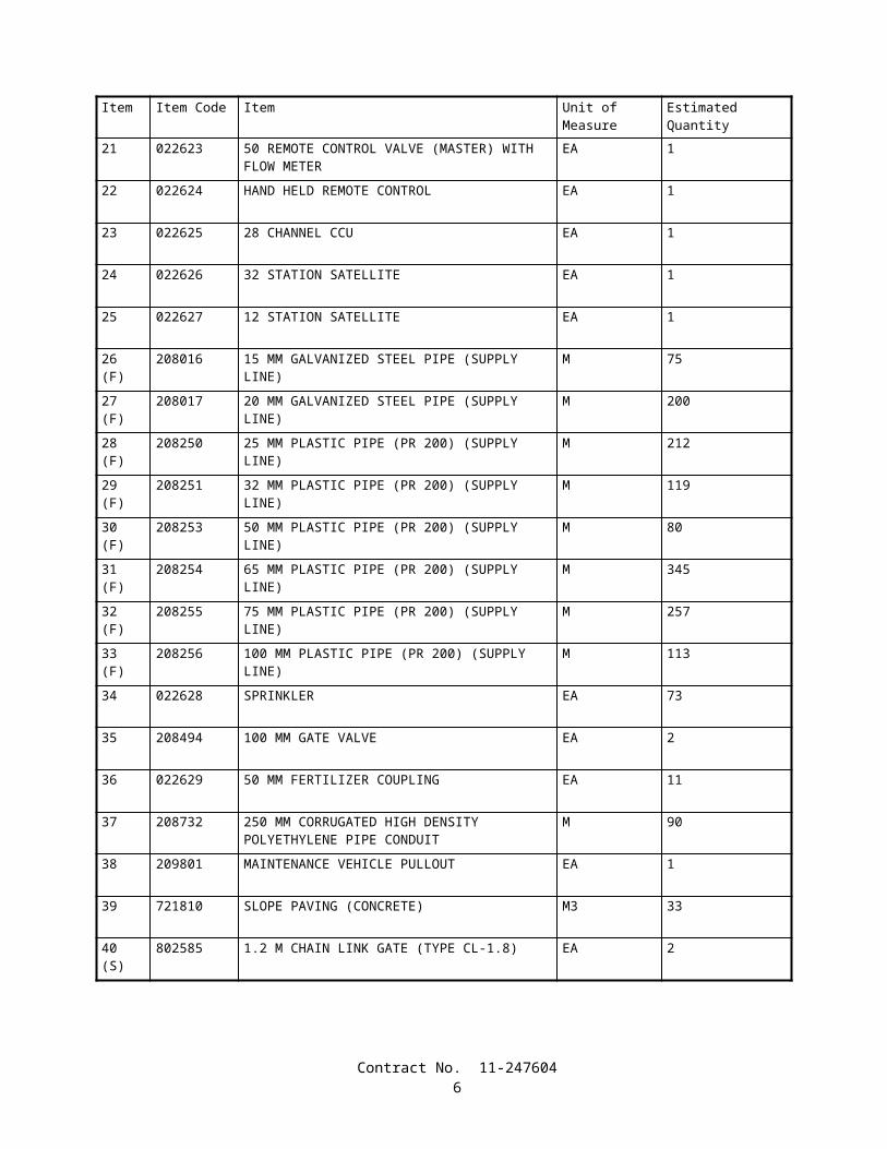
Item Item Code Item Unit of Measure Estimated Quantity
21 022623 50 REMOTE CONTROL VALVE (MASTER) WITH FLOW METER
EA 1
22 022624 HAND HELD REMOTE CONTROL EA 1
23 022625 28 CHANNEL CCU EA 1
24 022626 32 STATION SATELLITE EA 1
25 022627 12 STATION SATELLITE EA 1
26(F)
208016 15 MM GALVANIZED STEEL PIPE (SUPPLY LINE) M 75
27(F)
208017 20 MM GALVANIZED STEEL PIPE (SUPPLY LINE) M 200
28(F)
208250 25 MM PLASTIC PIPE (PR 200) (SUPPLY LINE) M 212
29(F)
208251 32 MM PLASTIC PIPE (PR 200) (SUPPLY LINE) M 119
30(F)
208253 50 MM PLASTIC PIPE (PR 200) (SUPPLY LINE) M 80
31(F)
208254 65 MM PLASTIC PIPE (PR 200) (SUPPLY LINE) M 345
32(F)
208255 75 MM PLASTIC PIPE (PR 200) (SUPPLY LINE) M 257
33(F)
208256 100 MM PLASTIC PIPE (PR 200) (SUPPLY LINE) M 113
34 022628 SPRINKLER EA 73
35 208494 100 MM GATE VALVE EA 2
36 022629 50 MM FERTILIZER COUPLING EA 11
37 208732 250 MM CORRUGATED HIGH DENSITY POLYETHYLENE PIPE CONDUIT
M 90
38 209801 MAINTENANCE VEHICLE PULLOUT EA 1
39 721810 SLOPE PAVING (CONCRETE) M3 33
40(S)
802585 1.2 M CHAIN LINK GATE (TYPE CL-1.8) EA 2
Contract No. 11-2476044

Item Item Code Item Unit of Measure Estimated Quantity
41(S)
860640 IRRIGATION CONTROLLER ENCLOSURE CABINET EA 1
42(S)
860797 ELECTRIC SERVICE (IRRIGATION) LS LUMP SUM
43 999990 MOBILIZATION LS LUMP SUM
Contract No. 11-2476045
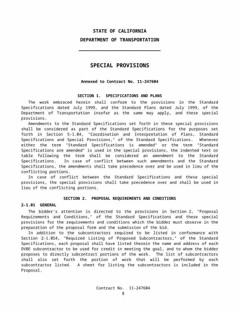
STATE OF CALIFORNIA
DEPARTMENT OF TRANSPORTATION
_____________________________
SPECIAL PROVISIONS
Annexed to Contract No. 11-247604
SECTION 1. SPECIFICATIONS AND PLANSThe work embraced herein shall conform to the provisions in the Standard Specifications dated July 1999, and the
Standard Plans dated July 1999, of the Department of Transportation insofar as the same may apply, and these special provisions.
Amendments to the Standard Specifications set forth in these special provisions shall be considered as part of the Standard Specifications for the purposes set forth in Section 5-1.04, "Coordination and Interpretation of Plans, Standard Specifications and Special Provisions," of the Standard Specifications. Whenever either the term "Standard Specifications is amended" or the term "Standard Specifications are amended" is used in the special provisions, the indented text or table following the term shall be considered an amendment to the Standard Specifications. In case of conflict between such amendments and the Standard Specifications, the amendments shall take precedence over and be used in lieu of the conflicting portions.
In case of conflict between the Standard Specifications and these special provisions, the special provisions shall take precedence over and shall be used in lieu of the conflicting portions.
SECTION 2. PROPOSAL REQUIREMENTS AND CONDITIONS2-1.01 GENERAL
The bidder's attention is directed to the provisions in Section 2, "Proposal Requirements and Conditions," of the Standard Specifications and these special provisions for the requirements and conditions which the bidder must observe in the preparation of the proposal form and the submission of the bid.
In addition to the subcontractors required to be listed in conformance with Section 2-1.054, "Required Listing of Proposed Subcontractors," of the Standard Specifications, each proposal shall have listed therein the name and address of each DVBE subcontractor to be used for credit in meeting the goal, and to whom the bidder proposes to directly subcontract portions of the work. The list of subcontractors shall also set forth the portion of work that will be performed by each subcontractor listed. A sheet for listing the subcontractors is included in the Proposal.
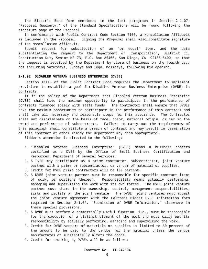
The Bidder's Bond form mentioned in the last paragraph in Section 2-1.07, "Proposal Guaranty," of the Standard Specifications will be found following the signature page of the Proposal.
In conformance with Public Contract Code Section 7106, a Noncollusion Affidavit is included in the Proposal. Signing the Proposal shall also constitute signature of the Noncollusion Affidavit.
Submit request for substitution of an "or equal" item, and the data substantiating the request to the Department of Transportation, District 11, Construction Duty Senior MS 73, P.O. Box 85406, San Diego, CA. 92186-5400, so that the request is received by the Department by close of business on the fourth day, not including Saturdays, Sundays and legal holidays, following bid opening.
2-1.02 DISABLED VETERAN BUSINESS ENTERPRISE (DVBE)Section 10115 of the Public Contract Code requires the Department to implement provisions to establish a goal for
Disabled Veteran Business Enterprise (DVBE) in contracts.It is the policy of the Department that Disabled Veteran Business Enterprise (DVBE) shall have the maximum
opportunity to participate in the performance of contracts financed solely with state funds. The Contractor shall ensure that DVBEs have the maximum opportunity to participate in the performance of this contract and shall take all necessary and reasonable steps for this assurance. The Contractor shall not discriminate on the basis of race, color, national origin, or sex in the award and performance of subcontracts. Failure to carry out the requirements of this paragraph shall constitute a breach of contract and may result in termination of this contract or other remedy the Department may deem appropriate.
Bidder's attention is directed to the following:
Contract No. 11-2476046
A. "Disabled Veteran Business Enterprise" (DVBE) means a business concern certified as a DVBE by the Office of Small Business Certification and Resources, Department of General Services.
B. A DVBE may participate as a prime contractor, subcontractor, joint venture partner with a prime or subcontractor, or vendor of material or supplies.
C. Credit for DVBE prime contractors will be 100 percent.D. A DVBE joint venture partner must be responsible for specific contract items of work, or portions thereof.
Responsibility means actually performing, managing and supervising the work with its own forces. The DVBE joint venture partner must share in the ownership, control, management responsibilities, risks and profits of the joint venture. The DVBE joint venturer must submit the joint venture agreement with the Caltrans Bidder DVBE Information form required in Section 2-1.04, "Submission of DVBE Information," elsewhere in these special provisions.
E. A DVBE must perform a commercially useful function, i.e., must be responsible for the execution of a distinct element of the work and must carry out its responsibility by actually performing, managing and supervising the work.
F. Credit for DVBE vendors of materials or supplies is limited to 60 percent of the amount to be paid to the vendor for the material unless the vendor manufactures or substantially alters the goods.
G. Credit for trucking by DVBEs will be as follows:
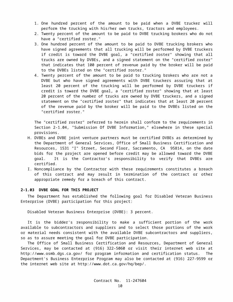
1. One hundred percent of the amount to be paid when a DVBE trucker will perform the trucking with his/her own trucks, tractors and employees.
2. Twenty percent of the amount to be paid to DVBE trucking brokers who do not have a "certified roster."3. One hundred percent of the amount to be paid to DVBE trucking brokers who have signed agreements that all
trucking will be performed by DVBE truckers if credit is toward the DVBE goal, a "certified roster" showing that all trucks are owned by DVBEs, and a signed statement on the "certified roster" that indicates that 100 percent of revenue paid by the broker will be paid to the DVBEs listed on the "certified roster."
4. Twenty percent of the amount to be paid to trucking brokers who are not a DVBE but who have signed agreements with DVBE truckers assuring that at least 20 percent of the trucking will be performed by DVBE truckers if credit is toward the DVBE goal, a "certified roster" showing that at least 20 percent of the number of trucks are owned by DVBE truckers, and a signed statement on the "certified roster" that indicates that at least 20 percent of the revenue paid by the broker will be paid to the DVBEs listed on the "certified roster."
The "certified roster" referred to herein shall conform to the requirements in Section 2-1.04, "Submission Of DVBE Information," elsewhere in these special provisions.
H. DVBEs and DVBE joint venture partners must be certified DVBEs as determined by the Department of General Services, Office of Small Business Certification and Resources, 1531 "I" Street, Second Floor, Sacramento, CA 95814, on the date bids for the project are opened before credit may be allowed toward the DVBE goal. It is the Contractor's responsibility to verify that DVBEs are certified.
I. Noncompliance by the Contractor with these requirements constitutes a breach of this contract and may result in termination of the contract or other appropriate remedy for a breach of this contract.
2-1.03 DVBE GOAL FOR THIS PROJECTThe Department has established the following goal for Disabled Veteran Business Enterprise (DVBE) participation for
this project:
Disabled Veteran Business Enterprise (DVBE): 3 percent.
It is the bidder's responsibility to make a sufficient portion of the work available to subcontractors and suppliers and to select those portions of the work or material needs consistent with the available DVBE subcontractors and suppliers, so as to assure meeting the goal for DVBE participation.
The Office of Small Business Certification and Resources, Department of General Services, may be contacted at (916) 322-5060 or visit their internet web site at http://www.osmb.dgs.ca.gov/ for program information and certification status. The Department's Business Enterprise Program may also be contacted at (916) 227-9599 or the internet web site at http://www.dot.ca.gov/hq/bep/.
Contract No. 11-2476047

2-1.04 SUBMISSION OF DVBE INFORMATIONThe required DVBE information shall be submitted on the "CALTRANS BIDDER - DVBE INFORMATION" form
included in the Proposal. If this information is not submitted with the bid, the DVBE information forms shall be removed from the documents prior to submitting the bid.
It is the bidder's responsibility to make enough work available to DVBEs and to select those portions of the work or material needs consistent with the available DVBEs to meet the goal for DVBE participation or to provide information to establish that, prior to bidding, the bidder made adequate good faith efforts to do so.
If the DVBE information is not submitted with the bid, the apparent successful bidder (low bidder), the second low bidder and the third low bidder shall submit the DVBE information to the Department of Transportation, 1120 N Street, Room 0200, MS #26, Sacramento, California 95814 so the information is received by the Department no later than 4:00 p.m. on the fourth day, not including Saturdays, Sundays and legal holidays, following bid opening. DVBE information sent by U.S. Postal Service certified mail with return receipt and certificate of mailing and mailed on or before the third day, not including Saturdays, Sundays and legal holidays, following bid opening will be accepted even if it is received after the fourth day following bid opening. Failure to submit the required DVBE information by the time specified will be grounds for finding the bid or proposal nonresponsive. Other bidders need not submit DVBE information unless requested to do so by the Department.
The bidder's DVBE information shall establish that good faith efforts to meet the DVBE goal have been made. To establish good faith efforts, the bidder shall demonstrate that the goal will be met or that, prior to bidding, adequate good faith efforts to meet the goal were made.
Bidders are cautioned that even though their submittal indicates they will meet the stated DVBE goal, their submittal should also include their adequate good faith efforts information along with their DVBE goal information to protect their eligibility for award of the contract in the event the Department, in its review, finds that the goal has not been met.
The bidder's DVBE information shall include the names of DVBE firms that will participate, with a complete description of work or supplies to be provided by each, the dollar value of each DVBE transaction, and a written confirmation from the DVBE that it is participating in the contract. A copy of the DVBE's quote will serve as written confirmation that the DVBE is participating in the contract. When 100 percent of a contract item of work is not to be performed or furnished by a DVBE, a description of the exact portion of that work to be performed or furnished by that DVBE shall be included in the DVBE information, including the planned location of that work. The work that a DVBE prime contractor has committed to performing with its own forces as well as the work that it has committed to be performed by DVBE subcontractors, suppliers and trucking companies will count toward the goal.
If credit for trucking by a DVBE trucking broker is shown on the bidder's information as 100 percent of the revenue to be paid by the broker is to be paid to DVBE truckers, a "certified roster" of the broker's trucks to be used must be included. The "certified roster" must indicate that all the trucks are owned by certified DVBEs and must show the DVBE truck numbers, owner's name, Public Utilities Commission Cal-T numbers, and the DVBE certification numbers. The roster must indicate that all revenue paid by the broker will be paid to DVBEs listed on the "certified roster".
If credit for trucking by a trucking broker who is not a DVBE is shown in the bidder's information, a "certified roster" of the broker's trucks to be used must be included. The "certified roster" must indicate that at least 20 percent of the broker's trucks are owned by certified DVBEs and must show the DVBE truck numbers, owner's name, Public Utilities Commission Cal-T numbers, and the DVBE certification number. The roster must indicate that at least 20 percent of the revenue paid by the broker will be paid to DVBEs listed on the "certified roster".
A bidder shall be deemed to have made good faith efforts upon submittal, within time limits specified by the Department, of documentary evidence that all of the following actions were taken:
A. Contact was made with the Office of Small Business Certification and Resources (OSBCR), Department of General Services or their web site at http://www.osmb.dgs.ca.gov/ to identify Disabled Veteran Business Enterprises.
B. Advertising was published in trade media and media focusing on Disabled Veteran Business Enterprises, unless time limits imposed by the Department do not permit that advertising.
C. Invitations to bid were submitted to potential Disabled Veteran Business Enterprise contractors.D. Available Disabled Veteran Business Enterprises were considered.
2-1.05 SMALL BUSINESS PREFERENCEAttention is directed to "Award and Execution of Contract" of these special provisions.Attention is also directed to the Small Business Procurement and Contract Act, Government Code Section 14835, et seq
and Title 2, California Code of Regulations, Section 1896, et seq.Bidders who wish to be classified as a Small Business under the provisions of those laws and regulations, shall be
certified as Small Business by the Department of General Services, Office of Small Business Certification and Resources, 1531 "I" Street, Second Floor, Sacramento, CA 95814.
Contract No. 11-2476048
To request Small Business Preference, bidders shall fill out and sign the Request for Small Business Preference form in the Proposal and shall attach a copy of their Office of Small Business Certification and Resources (OSBCR) small business certification letter to the form. The bidder's signature on the Request for Small Business Preference certifies, under penalty of perjury, that the bidder is certified as Small Business at the time of bid opening and further certifies, under penalty of perjury, that under the following conditions, at least 50 percent of the subcontractors to be utilized on the project are either certified Small Business or have applied for Small Business certification by bid opening date and are subsequently granted Small Business certification.
The conditions requiring the aforementioned 50 percent level of subcontracting by Small Business subcontractors apply if:
A. The lowest responsible bid for the project exceeds $100,000; andB. The project work to be performed requires a Class A or a Class B contractor's license; andC. Two or more subcontractors will be used.
If the above conditions apply and Small Business Preference is granted in the award of the contract, the 50 percent Small Business subcontractor utilization level shall be maintained throughout the life of the contract.
2-1.06 CALIFORNIA COMPANY PREFERENCEAttention is directed to "Award and Execution of Contract" of these special provisions.In conformance with the requirements of Section 6107 of the Public Contract Code, a "California company" will be
granted a reciprocal preference for bid comparison purposes as against a nonresident contractor from any state that gives or requires a preference to be given contractors from that state on its public entity construction contracts.
A "California company" means a sole proprietorship, partnership, joint venture, corporation, or other business entity that was a licensed California contractor on the date when bids for the public contract were opened and meets one of the following:
A. Has its principal place of business in California.B. Has its principal place of business in a state in which there is no local contractor preference on construction
contracts.C. Has its principal place of business in a state in which there is a local contractor construction preference and the
contractor has paid not less than $5000 in sales or use taxes to California for construction related activity for each of the five years immediately preceding the submission of the bid.
To carry out the "California company" reciprocal preference requirements of Section 6107 of the Public Contract Code, all bidders shall fill out and sign the California Company Preference form in the Proposal. The bidder's signature on the California Company Preference form certifies, under penalty of perjury, that the bidder is or is not a "California company" and if not, the amount of the preference applied by the state of the nonresident Contractor.
A nonresident Contractor shall disclose any and all bid preferences provided to the nonresident Contractor by the state or country in which the nonresident Contractor has its principal place of business.
Proposals without the California Company Preference form filled out and signed may be rejected.
SECTION 3. AWARD AND EXECUTION OF CONTRACTThe bidder's attention is directed to the provisions in Section 3, "Award and Execution of Contract," of the Standard
Specifications and these special provisions for the requirements and conditions concerning award and execution of contract.The award of the contract, if it be awarded, will be to the lowest responsible bidder whose proposal complies with all the
requirements prescribed and who has met the goal for DVBE participation or has demonstrated, to the satisfaction of the Department, adequate good faith efforts to do so. Meeting the goal for DVBE participation or demonstrating, to the satisfaction of the Department, adequate good faith efforts to do so is a condition for being eligible for award of contract.
A "Payee Data Record" form will be included in the contract documents to be executed by the successful bidder. The purpose of the form is to facilitate the collection of taxpayer identification data. The form shall be completed and returned to the Department by the successful bidder with the executed contract and contract bonds. For the purposes of the form, payee shall be deemed to mean the successful bidder. The form is not to be completed for subcontractors or suppliers. Failure to complete and return the "Payee Data Record" form to the Department as provided herein will result in the retention of 20 percent of payments due the contractor and penalties of up to $20,000. This retention of payments for failure to complete the "Payee Data Record" form is in addition to any other retention of payments due the Contractor.
Attention is also directed to "Small Business Preference" of these special provisions. Any bidder who is certified as a Small Business by the Department of General Services, Office of Small Business Certification and Resources will be allowed a preference in the award of this contract, if it be awarded, under the following conditions:
Contract No. 11-2476049
A. The apparent low bidder is not certified as a Small Business, or has not filled out and signed the Request for Small Business Preference included with the bid documents and attached a copy of their Office of Small Business Certification and Resources (OSBCR) small business certification letter to the form; and
B. The bidder filled out and signed the Request for Small Business Preference form included with the bid documents and attached a copy of their Office of Small Business Certification and Resources (OSBCR) small business certification letter to the form.
The small business preference will be a reduction in the bid submitted by the small business contractor, for bid comparison purposes, by an amount equal to 5 percent of the amount bid by the apparent low bidder, the amount not to exceed $50,000. If this reduction results in the small business contractor becoming the low bidder, then the contract will be awarded to the small business contractor on the basis of the actual bid of the small business contractor notwithstanding the reduced bid price used for bid comparison purposes.
Attention is also directed to "California Company Preference" of these special provisions.The amount of the California company reciprocal preference shall be equal to the amount of the preference applied by
the state of the nonresident contractor with the lowest responsive bid, except where the "California company" is eligible for a California Small Business Preference, in which case the preference applied shall be the greater of the two, but not both.
If the bidder submitting the lowest responsive bid is not a "California company" and with the benefit of the reciprocal preference, a "California company's" responsive bid is equal to or less than the original lowest responsive bid, the "California company" will be awarded the contract at its submitted bid price except as provided below.
Small business bidders shall have precedence over nonsmall business bidders in that the application of the "California company" preference for which nonsmall business bidders may be eligible shall not result in the denial of the award to a small business bidder.
SECTION 4. BEGINNING OF WORK, TIME OF COMPLETION AND LIQUIDATED DAMAGESAttention is directed to the provisions in Section 8-1.03, "Beginning of Work," in Section 8-1.06, "Time of Completion,"
and in Section 8-1.07, "Liquidated Damages," of the Standard Specifications and these special provisions.The Contractor shall begin work within 15 calendar days after the contract has been approved by the Attorney General or
the attorney appointed and authorized to represent the Department of Transportation.The work shall be diligently prosecuted to completion before the expiration of 340 WORKING DAYS beginning on the
fifteenth calendar day after approval of the contract.The Contractor shall pay to the State of California the sum of $250 per day, for each and every calendar day's delay in
finishing the work in excess of the number of working days prescribed above.
SECTION 5. GENERAL
SECTION 5-1. MISCELLANEOUS
5-1.01 PLANS AND WORKING DRAWINGSWhen the specifications require working drawings to be submitted to the Division of Structure Design, the drawings
shall be submitted to: Division of Structure Design, Documents Unit, Mail Station 9, 1801 30th Street, Sacramento, CA 95816, Telephone 916 227-8252.
5-1.011 EXAMINATION OF PLANS, SPECIFICATIONS, CONTRACT, AND SITE OF WORKThe second paragraph of Section 2-1.03, "Examination of Plans, Specifications, Contract, and Site of Work," of the
Standard Specifications is amended to read:
• Where the Department has made investigations of site conditions, including subsurface conditions in areas where work is to be performed under the contract, or in other areas, some of which may constitute possible local material sources, bidders or Contractors may, upon written request, inspect the records of the Department as to those investigations subject to and upon the conditions hereinafter set forth.
Attention is directed to "Differing Site Conditions" of these special provisions regarding physical conditions at the site which may differ from those indicated in "Materials Information," log of test borings or other geotechnical information obtained by the Department's investigation of site conditions.
Contract No. 11-24760410
5-1.012 DIFFERING SITE CONDITIONSAttention is directed to Section 5-1.116, "Differing Site Conditions," of the Standard Specifications.During the progress of the work, if subsurface or latent conditions are encountered at the site differing materially from
those indicated in the "Materials Information," log of test borings, other geotechnical data obtained by the Department's investigation of subsurface conditions, or an examination of the conditions above ground at the site, the party discovering those conditions shall promptly notify the other party in writing of the specific differing conditions before they are disturbed and before the affected work is performed.
The Contractor will be allowed 15 days from the notification of the Engineer's determination of whether or not an adjustment of the contract is warranted, in which to file a notice of potential claim in conformance with the provisions of Section 9-1.04, "Notice of Potential Claim," of the Standard Specifications and as specified herein; otherwise the decision of the Engineer shall be deemed to have been accepted by the Contractor as correct. The notice of potential claim shall set forth in what respects the Contractor's position differs from the Engineer's determination and provide any additional information obtained by the Contractor, including but not limited to additional geotechnical data. The notice of potential claim shall be accompanied by the Contractor's certification that the following were made in preparation of the bid: a review of the contract, a review of the "Materials Information," a review of the log of test borings and other records of geotechnical data to the extent they were made available to bidders prior to the opening of bids, and an examination of the conditions above ground at the site. Supplementary information, obtained by the Contractor subsequent to the filing of the notice of potential claim, shall be submitted to the Engineer in an expeditious manner.
5-1.015 LABORATORYWhen a reference is made in the specifications to the "Laboratory," the reference shall mean the Division of Materials
Engineering and Testing Services and the Division of Structural Foundations of the Department of Transportation, or established laboratories of the various Districts of the Department, or other laboratories authorized by the Department to test materials and work involved in the contract. When a reference is made in the specifications to the "Transportation Laboratory," the reference shall mean the Division of Materials Engineering and Testing Services and the Division of Structural Foundations, located at 5900 Folsom Boulevard, Sacramento, CA 95819, Telephone (916) 227-7000.
5-1.017 CONTRACT BONDSAttention is directed to Section 3-1.02, "Contract Bonds," of the Standard Specifications and these special provisions.The payment bond shall be in a sum not less than one hundred percent of the total amount payable by the terms of the
contract.
5-1.018 EXCAVATION SAFETY PLANSSection 5-1.02A, "Trench Excavation Safety Plans," of the Standard Specifications is amended to read:
5-1.02A Excavation Safety Plans• The Construction Safety Orders of the Division of Occupational Safety and Health shall apply to all excavations. For all excavations 1.5 m or more in depth, the Contractor shall submit to the Engineer a detailed plan showing the design and details of the protective systems to be provided for worker protection from the hazard of caving ground during excavation. The detailed plan shall include any tabulated data and any design calculations used in the preparation of the plan. Excavation shall not begin until the detailed plan has been reviewed and approved by the Engineer.• Detailed plans of protective systems for which the Construction Safety Orders require design by a registered professional engineer shall be prepared and signed by an engineer who is registered as a Civil Engineer in the State of California, and shall include the soil classification, soil properties, soil design calculations that demonstrate adequate stability of the protective system, and any other design calculations used in the preparation of the plan.• No plan shall allow the use of a protective system less effective than that required by the Construction Safety Orders.• If the detailed plan includes designs of protective systems developed only from the allowable configurations and slopes, or Appendices, contained in the Construction Safety Orders, the plan shall be submitted at least 5 days before the Contractor intends to begin excavation. If the detailed plan includes designs of protective systems developed from tabulated data, or designs for which design by a registered professional engineer is required, the plan shall be submitted at least 3 weeks before the Contractor intends to begin excavation.• Attention is directed to Section 7-1.01E, "Trench Safety."
The third paragraph of Section 19-1.02, "Preservation of Property," of the Standard Specifications is amended to read:
Contract No. 11-24760411
• In addition to the provisions in Sections 5-1.02, "Plans and Working Drawings," and 5-1.02A, "Excavation Safety Plans," detailed plans of the protective systems for excavations on or affecting railroad property will be reviewed for adequacy of protection provided for railroad facilities, property, and traffic. These plans shall be submitted at least 9 weeks before the Contractor intends to begin excavation requiring the protective systems. Approval by the Engineer of the detailed plans for the protective systems will be contingent upon the plans being satisfactory to the railroad company involved.
5-1.019 COST REDUCTION INCENTIVEAttention is directed to Section 5-1.14, "Cost Reduction Incentive," of the Standard Specifications.Prior to preparing a cost reduction proposal, the Contractor shall request a meeting with the Engineer to discuss the
proposal in concept and to determine the merit of the cost reduction proposal. Items of discussion will also include permit issues, impact on other projects, impact on the project schedule, peer reviews, and review times required by the Department and other agencies.
5-1.02 LABOR NONDISCRIMINATIONAttention is directed to the following Notice that is required by Chapter 5 of Division 4 of Title 2, California Code of
Regulations.
NOTICE OF REQUIREMENT FOR NONDISCRIMINATION PROGRAM
(GOV. CODE, SECTION 12990)Your attention is called to the "Nondiscrimination Clause", set forth in Section 7-1.01A(4), "Labor Nondiscrimination," of the Standard Specifications, which is applicable to all nonexempt State contracts and subcontracts, and to the "Standard California Nondiscrimination Construction Contract Specifications" set forth therein. The specifications are applicable to all nonexempt State construction contracts and subcontracts of $5000 or more.
5-1.03 INTEREST ON PAYMENTSInterest shall be payable on progress payments, payments after acceptance, final payments, extra work payments, and
claim payments as follows:
A. Unpaid progress payments, payment after acceptance, and final payments shall begin to accrue interest 30 days after the Engineer prepares the payment estimate.
B. Unpaid extra work bills shall begin to accrue interest 30 days after preparation of the first pay estimate following receipt of a properly submitted and undisputed extra work bill. To be properly submitted, the bill must be submitted within 7 days of the performance of the extra work and in conformance with the provisions in Section 9 -1.03C, "Records," and Section 9-1.06, "Partial Payments," of the Standard Specifications. An undisputed extra work bill not submitted within 7 days of performance of the extra work will begin to accrue interest 30 days after the preparation of the second pay estimate following submittal of the bill.
C. The rate of interest payable for unpaid progress payments, payments after acceptance, final payments, and extra work payments shall be 10 percent per annum.
D. The rate of interest payable on a claim, protest or dispute ultimately allowed under this contract shall be 6 percent per annum. Interest shall begin to accrue 61 days after the Contractor submits to the Engineer information in sufficient detail to enable the Engineer to ascertain the basis and amount of said claim, protest or dispute.
The rate of interest payable on any award in arbitration shall be 6 percent per annum if allowed under the provisions of Civil Code Section 3289.
5-1.031 FINAL PAYMENT AND CLAIMSAttention is directed to Section 9-1.07B, "Final Payment and Claims," of the Standard Specifications.If the Contractor files a timely written statement of claims in response to the proposed final estimate, the District that
administers the contract will submit a claim position letter to the Contractor by hand delivery or deposit in the U.S. mail within 135 days of acceptance of the contract. The claim position letter will delineate the District's position on the Contractor's claims. If the Contractor disagrees with the claim position letter, the Contractor shall submit a written notification of its disagreement to be received by the District not later than 15 days after the Contractor's receipt of the claim position letter. The written notification of disagreement shall set forth the basis for the Contractor's disagreement and be submitted to the office designated in the claim position letter. The Contractor's failure to provide a timely, written
Contract No. 11-24760412
notification of disagreement shall constitute the Contractor's acceptance and agreement with the determinations provided in the claim position letter and with final payment pursuant to the claim position letter.
If the Contractor files a timely notification of disagreement with the District claim position letter, the board of review designated by the District Director to review claims that remain in dispute will meet with the Contractor within 45 days after receipt by the District of the notification of disagreement. Attendance by the Contractor at the board of review meeting shall be mandatory.
If the District fails to submit a claim position letter to the Contractor within 135 days after the acceptance of the contract and the Contractor has claims that remain in dispute, the Contractor may request a meeting with the board of review designated by the District Director to review claims that remain in dispute. The Contractor's request for a meeting shall identify the claims that remain in dispute. If the Contractor files a request for a meeting, the board of review will meet with the Contractor within 45 days after the District receives the request for the meeting. Attendance by the Contractor at the District Director's board of review meeting shall be mandatory.
Failure of the Contractor to file a timely written statement of claims in response to the proposed final estimate, or to file a timely notification of disagreement with the District claim position letter, or to attend the District Director's board of review meeting shall constitute a failure to pursue diligently and exhaust the administrative procedures in the contract and shall be a bar to arbitration in conformance with the requirements in Section 10240.2 of the California Public Contract Code.
5-1.04 PUBLIC SAFETYThe Contractor shall provide for the safety of traffic and the public in conformance with the provisions in Section 7 -1.09,
"Public Safety," of the Standard Specifications and these special provisions.The Contractor shall install temporary railing (Type K) between a lane open to public traffic and an excavation, obstacle
or storage area when the following conditions exist:
A. Excavations.—The near edge of the excavation is 3.6 m or less from the edge of the lane, except:
1. Excavations covered with sheet steel or concrete covers of adequate thickness to prevent accidental entry by traffic or the public.
2. Excavations less than 0.3-m deep.3. Trenches less than 0.3-m wide for irrigation pipe or electrical conduit, or excavations less than 0.3-m in
diameter.4. Excavations parallel to the lane for the purpose of pavement widening or reconstruction.5. Excavations in side slopes, where the slope is steeper than 1:4 (vertical:horizontal).6. Excavations protected by existing barrier or railing.
B. Temporarily Unprotected Permanent Obstacles.—The work includes the installation of a fixed obstacle together with a protective system, such as a sign structure together with protective railing, and the Contractor elects to install the obstacle prior to installing the protective system; or the Contractor, for the Contractor's convenience and with permission of the Engineer, removes a portion of an existing protective railing at an obstacle and does not replace such railing complete in place during the same day.
C. Storage Areas.—Material or equipment is stored within 3.6 m of the lane and the storage is not otherwise prohibited by the provisions of the Standard Specifications and these special provisions.
The approach end of temporary railing (Type K), installed in conformance with the provisions in this section "Public Safety" and in Section 7-1.09, "Public Safety," of the Standard Specifications, shall be offset a minimum of 4.6 m from the edge of the traffic lane open to public traffic. The temporary railing shall be installed on a skew toward the edge of the traffic lane of not more than 0.3-m transversely to 3 m longitudinally with respect to the edge of the traffic lane. If the 4.6 -m minimum offset cannot be achieved, the temporary railing shall be installed on the 10 to 1 skew to obtain the maximum available offset between the approach end of the railing and the edge of the traffic lane, and an array of temporary crash cushion modules shall be installed at the approach end of the temporary railing.
Temporary railing (Type K) shall conform to the provisions in Section 12-3.08, "Temporary Railing (Type K)," of the Standard Specifications. Temporary railing (Type K), conforming to the details shown on 1999 Standard Plan T3, may be used. Temporary railing (Type K) fabricated prior to January 1, 1993, and conforming to 1988 Standard Plan B11-30 may be used, provided the fabrication date is printed on the required Certificate of Compliance.
Temporary crash cushion modules shall conform to the provisions in "Temporary Crash Cushion Module" of these special provisions.
Except for installing, maintaining and removing traffic control devices, whenever work is performed or equipment is operated in the following work areas, the Contractor shall close the adjacent traffic lane unless otherwise provided in the Standard Specifications and these special provisions:
Contract No. 11-24760413
Approach Speed of Public Traffic (Posted Limit) (Kilometers Per Hour)
Work Areas
Over 72 (45 Miles Per Hour) Within 1.8 m of a traffic lane but not on a traffic lane56 to 72 (35 to 45 Miles Per Hour) Within 0.9-m of a traffic lane but not on a traffic lane
The lane closure provisions of this section shall not apply if the work area is protected by permanent or temporary railing or barrier.
When traffic cones or delineators are used to delineate a temporary edge of a traffic lane, the line of cones or delineators shall be considered to be the edge of the traffic lane, however, the Contractor shall not reduce the width of an existing lane to less than 3 m without written approval from the Engineer.
When work is not in progress on a trench or other excavation that required closure of an adjacent lane, the traffic cones or portable delineators used for the lane closure shall be placed off of and adjacent to the edge of the traveled way. The spacing of the cones or delineators shall be not more than the spacing used for the lane closure.
Suspended loads or equipment shall not be moved nor positioned over public traffic or pedestrians.Full compensation for conforming to the provisions in this section "Public Safety," including furnishing and installing
temporary railing (Type K) and temporary crash cushion modules, shall be considered as included in the contract prices paid for the various items of work involved and no additional compensation will be allowed therefor.
5-1.05 SURFACE MINING AND RECLAMATION ACTAttention is directed to the Surface Mining and Reclamation Act of 1975, commencing in Public Resources Code,
Mining and Geology, Section 2710, which establishes regulations pertinent to surface mining operations, and to California Public Contract Code Section 10295.5.
Material from mining operations furnished for this project shall only come from permitted sites in compliance with California Public Contract Code Section 10295.5.
The requirements of this section shall apply to materials furnished for the project, except for acquisition of materials in conformance with the provisions in Section 4-1.05, "Use of Materials Found on the Work," of the Standard Specifications.
5-1.06 REMOVAL OF ASBESTOS AND HAZARDOUS SUBSTANCESWhen the presence of asbestos or hazardous substances are not shown on the plans or indicated in the specifications and
the Contractor encounters materials which the Contractor reasonably believes to be asbestos or a hazardous substance as defined in Section 25914.1 of the Health and Safety Code, and the asbestos or hazardous substance has not been rendered harmless, the Contractor may continue work in unaffected areas reasonably believed to be safe. The Contractor shall immediately cease work in the affected area and report the condition to the Engineer in writing.
In conformance with Section 25914.1 of the Health and Safety Code, removal of asbestos or hazardous substances including exploratory work to identify and determine the extent of the asbestos or hazardous substance will be performed by separate contract.
If delay of work in the area delays the current controlling operation, the delay will be considered a right of way delay and the Contractor will be compensated for the delay in conformance with the provisions in Section 8-1.09, "Right of Way Delays," of the Standard Specifications.
5-1.07 YEAR 2000 COMPLIANCEThis contract is subject to Year 2000 Compliance for automated devices in the State of California.Year 2000 compliance for automated devices in the State of California is achieved when embedded functions have or
create no logical or mathematical inconsistencies when dealing with dates prior to and beyond 1999. The year 2000 is recognized and processed as a leap year. The product shall operate accurately in the manner in which the product was intended for date operation without requiring manual intervention.
The Contractor shall provide the Engineer a Certificate of Compliance from the manufacturer in conformance with the provisions in Section 6-1.07, "Certificates of Compliance," of the Standard Specifications for all automated devices furnished for the project.
5-1.08 SUBCONTRACTOR AND DVBE RECORDSThe Contractor shall maintain records of all subcontracts entered into with certified DVBE subcontractors and records of
materials purchased from certified DVBE suppliers. The records shall show the name and business address of each DVBE subcontractor or vendor and the total dollar amount actually paid each DVBE subcontractor or vendor.
Upon completion of the contract, a summary of these records shall be prepared on Form CEM-2402 (S) and certified correct by the Contractor or the Contractor's authorized representative, and shall be furnished to the Engineer.
Contract No. 11-24760414
5-1.086 PERFORMANCE OF DVBE SUBCONTRACTORS AND SUPPLIERSThe DVBEs listed by the Contractor in response to the provisions in Section 2-1.04, "Submission of DVBE
Information," and Section 3, "Award and Execution of Contract," of these special provisions, which are determined by the Department to be certified DVBEs, shall perform the work and supply the materials for which they are listed, unless the Contractor has received prior written authorization to perform the work with other forces or to obtain the materials from other sources.
Authorization to utilize other forces or sources of materials may be requested for the following reasons:
A. The listed DVBE, after having had a reasonable opportunity to do so, fails or refuses to execute a written contract, when the written contract, based upon the general terms, conditions, plans and specifications for the project, or on the terms of the subcontractor's or supplier's written bid, is presented by the Contractor.
B. The listed DVBE becomes bankrupt or insolvent.C. The listed DVBE fails or refuses to perform the subcontract or furnish the listed materials.D. The Contractor stipulated that a bond was a condition of executing a subcontract and the listed DVBE subcontractor
fails or refuses to meet the bond requirements of the Contractor.E. The work performed by the listed subcontractor is substantially unsatisfactory and is not in substantial conformance
with the plans and specifications or the subcontractor is substantially delaying or disrupting the progress of the work.
F. The listed DVBE subcontractor is not licensed pursuant to the Contractor's License Law.G. It would be in the best interest of the State.
The Contractor shall not be entitled to payment for the work or material unless it is performed or supplied by the listed DVBE or by other forces (including those of the Contractor) pursuant to prior written authorization of the Engineer.
5-1.09 SUBCONTRACTINGAttention is directed to the provisions in Section 8-1.01, "Subcontracting," of the Standard Specifications, Section 2,
"Proposal Requirements and Conditions," Section 2-1.04, "Submission of DVBE Information," and Section 3, "Award and Execution of Contract," of these special provisions and these special provisions.
Pursuant to the provisions in Section 1777.1 of the Labor Code, the Labor Commissioner publishes and distributes a list of contractors ineligible to perform work as a subcontractor on a public works project. This list of debarred contractors is available from the Department of Industrial Relations web site at:
http://www.dir.ca.gov/DLSE/Debar.html.
The DVBE information furnished under Section 3-1.01A, "DVBE Information," of these special provisions is in addition to the subcontractor information required to be furnished in Section 8-1.01, "Subcontracting," and Section 2-1.054, "Required Listing of Proposed Subcontractors," of the Standard Specifications.
Section 10115 of the Public Contract Code requires the Department to implement provisions to establish a goal for Disabled Veteran Business Enterprise (DVBE) participation in highway contracts that are State funded. As a part of this requirement:
A. No substitution of a DVBE subcontractor shall be made at any time without the written consent of the Department, and
B. If a DVBE subcontractor is unable to perform successfully and is to be replaced, the Contractor shall make good faith efforts to replace the original DVBE subcontractor with another DVBE subcontractor.
The provisions in Section 2-1.02, "Disabled Veteran Business Enterprise (DVBE)," of these special provisions that DVBEs shall be certified on the date bids are opened does not apply to DVBE substitutions after award of the contract.
5-1.10 PROMPT PROGRESS PAYMENT TO SUBCONTRACTORSAttention is directed to the provisions in Sections 10262 and 10262.5 of the Public Contract Code and Section 7108.5 of
the Business and Professions Code concerning prompt payment to subcontractors.
Contract No. 11-24760415
5-1.11 ENVIRONMENTALLY SENSITIVE AREA (ESA)The Contractor's attention is directed to the areas designated on the plans as "Environmentally Sensitive Area," and to
certain State and Federal regulations which may pertain to such areas. These areas shall be completely avoided by all parties involved in any work activity in connection with the performance of this contract.
5-1.12 AREAS FOR CONTRACTOR'S USEAttention is directed to the provisions in Section 7-1.19, "Rights in Land and Improvements," of the Standard
Specifications and these special provisions.The highway right of way shall be used only for purposes that are necessary to perform the required work. The
Contractor shall not occupy the right of way, or allow others to occupy the right of way, for purposes which are not necessary to perform the required work.
No State-owned parcels adjacent to the right of way are available for the exclusive use of the Contractor within the contract limits. The Contractor shall secure, at the Contractor's own expense, areas required for plant sites, storage of equipment or materials, or for other purposes.
No area is available within the contract limits for the exclusive use of the Contractor. However, temporary storage of equipment and materials on State property may be arranged with the Engineer, subject to the prior demands of State maintenance forces and to other contract requirements. Use of the Contractor's work areas and other State-owned property shall be at the Contractor's own risk, and the State shall not be held liable for damage to or loss of materials or equipment located within such areas.
5-1.13 PAYMENTSAttention is directed to Sections 9-1.06, "Partial Payments," and 9-1.07, "Payment After Acceptance," of the Standard
Specifications and these special provisions.For the purpose of making partial payments pursuant to Section 9-1.06, "Partial Payments," of the Standard
Specifications, the amount set forth for the contract items of work hereinafter listed shall be deemed to be the maximum value of the contract item of work which will be recognized for progress payment purposes:
Roadside Clearing $10,000
After acceptance of the contract pursuant to the provisions in Section 7-1.17, "Acceptance of Contract," of the Standard Specifications, the amount, if any, payable for a contract item of work in excess of the maximum value for progress payment purposes hereinabove listed for the item, will be included for payment in the first estimate made after acceptance of the contract.
In determining the partial payments to be made to the Contractor, only the following listed materials will be considered for inclusion in the payment as materials furnished but not incorporated in the work:
A. Pipe (Irrigation Systems)B. Remote Control ValvesC. Irrigation ControllersD. Irrigation Controller Enclosure Cabinets
5-1.14 SOUND CONTROL REQUIREMENTSSound control shall conform to the provisions in Section 7-1.01I, "Sound Control Requirements," of the Standard
Specifications and these special provisions.The noise level from the Contractor's operations, between the hours of 7:00 p.m. and 7:00 a.m., shall not exceed 86 dbA
at a distance of 15 m. This requirement shall not relieve the Contractor from responsibility for complying with local ordinances regulating noise level outside the limits of the State right of way.
The noise level requirement specified herein shall apply to the equipment on the job or related to the job, including but not limited to trucks, transit mixers or transient equipment that may or may not be owned by the Contractor. The use of loud sound signals shall be avoided in favor of light warnings except those required by safety laws for the protection of personnel.
Full compensation for conforming to the requirements of this section shall be considered as included in the prices paid for the various contract items of work involved and no additional compensation will be allowed therefor.
Contract No. 11-24760416
SECTION 6. (BLANK)
SECTION 7. (BLANK)
SECTION 8. MATERIALS
SECTION 8-1. MISCELLANEOUS
8-1.01 SUBSTITUTION OF NON-METRIC MATERIALS AND PRODUCTSOnly materials and products conforming to the requirements of the specifications shall be incorporated in the work.
When metric materials and products are not available, and when approved by the Engineer, and at no cost to the State, materials and products in the United States Standard Measures which are of equal quality and of the required properties and characteristics for the purpose intended, may be substituted for the equivalent metric materials and products, subject to the following provisions:
A. Materials and products shown on the plans or in the special provisions as being equivalent may be substituted for the metric materials and products specified or detailed on the plans.
B. Before other non-metric materials and products will be considered for use, the Contractor shall furnish, at the Contractor's expense, evidence satisfactory to the Engineer that the materials and products proposed for use are equal to or better than the materials and products specified or detailed on the plans. The burden of proof as to the quality and suitability of substitutions shall be upon the Contractor and the Contractor shall furnish necessary information as required by the Engineer. The Engineer will be the sole judge as to the quality and suitability of the substituted materials and products and the Engineer's decision will be final.
C. When the Contractor elects to substitute non-metric materials and products, including materials and products shown on the plans or in the special provisions as being equivalent, the list of sources of material specified in Section 6-1.01, "Source of Supply and Quality of Materials," of the Standard Specification shall include a list of substitutions to be made and contract items involved. In addition, for a change in design or details, the Contractor shall submit plans and working drawings in conformance with the provisions in Section 5-1.02, "Plans and Working Drawings," of the Standard Specifications. The plans and working drawings shall be submitted at least 7 days before the Contractor intends to begin the work involved.
Unless otherwise specified, the following substitutions of materials and products will be allowed:
SUBSTITUTION TABLE FOR SIZES OF HIGH STRENGTH STEEL FASTENERS ASTM Designation: A 325M
METRIC SIZE SHOWN ON THE PLANSmm x thread pitch
SIZE TO BE SUBSTITUTED inch
M16 x 2 5/8M20 x 2.5 3/4M22 x 2.5 7/8M24 x 3 1M27 x 3 1-1/8
M30 x 3.5 1-1/4M36 x 4 1-1/2
Contract No. 11-24760417
SUBSTITUTION TABLE FOR PLAIN WIRE REINFORCEMENTASTM Designation: A 82
METRIC SIZE SHOWN ON THE PLANSmm2
SIZE TO BE SUBSTITUTEDinch2 x 100
MW9 W1.4MW10 W1.6MW13 W2.0MW15 W2.3MW19 W2.9MW20 W3.1MW22 W3.5MW25 W3.9, except W3.5 in piles onlyMW26 W4.0MW30 W4.7MW32 W5.0MW35 W5.4MW40 W6.2MW45 W6.5MW50 W7.8MW55 W8.5, except W8.0 in piles onlyMW60 W9.3MW70 W10.9, except W11.0 in piles onlyMW80 W12.4MW90 W14.0MW100 W15.5
SUBSTITUTION TABLE FOR BAR REINFORCEMENTMETRIC BAR DESIGNATION
NUMBER1 SHOWN ON THE PLANSBAR DESIGNATION
NUMBER2 TO BE SUBSTITUTED10 313 416 519 622 725 829 932 1036 1143 1457 18
1Bar designation numbers approximate the number of millimeters of the nominal diameter of the bars.2Bar numbers are based on the number of eighths of an inch included in the nominal diameter of the bars.No adjustment will be required in spacing or total number of reinforcing bars due to a difference in minimum yield strength between metric and non-metric bars.
Contract No. 11-24760418
SUBSTITUTION TABLE FOR SIZES OF:(1) STEEL FASTENERS FOR GENERAL APPLICATIONS (ASTM Designation: A 307 or AASHTO Designation: M 314, Grade 36 or 55), and (2) HIGH STRENGTH STEEL FASTENERS (ASTM Designation: A 325 or A 449)
METRIC SIZE SHOWN ON THE PLANSmm
SIZE TO BE SUBSTITUTEDinch
6 or 6.35 1/48 or 7.94 5/1610 or 9.52 3/811 or 11.11 7/1613 or 12.70 1/214 or 14.29 9/1616 or 15.88 5/819 or 19.05 3/422 or 22.22 7/8
24, 25, or 25.40 129 or 28.58 1-1/832 or 31.75 1-1/435 or 34.93 1-3/838 or 38.10 1-1/244 or 44.45 1-3/451 or 50.80 257 or 57.15 2-1/464 or 63.50 2-1/270 or 69.85 2-3/476 or 76.20 383 or 82.55 3-1/489 or 88.90 3-1/295 or 95.25 3-3/4
102 or 101.60 4
Contract No. 11-24760419
SUBSTITUTION TABLE FOR NOMINAL THICKNESS OF SHEET METALUNCOATED HOT AND COLD ROLLED SHEETS HOT-DIPPED ZINC COATED SHEETS
(GALVANIZED)METRIC THICKNESS
SHOWN ON THE PLANSmm
GAGE TO BE SUBSTITUTED
inch
METRIC THICKNESSSHOWN ON THE PLANS
mm
GAGE TO BE SUBSTITUTED
inch7.94 0.3125 4.270 0.16816.07 0.2391 3.891 0.15325.69 0.2242 3.510 0.13825.31 0.2092 3.132 0.12334.94 0.1943 2.753 0.10844.55 0.1793 2.372 0.09344.18 0.1644 1.994 0.07853.80 0.1495 1.803 0.07103.42 0.1345 1.613 0.06353.04 0.1196 1.461 0.05752.66 0.1046 1.311 0.05162.28 0.0897 1.158 0.04561.90 0.0747 1.006 or 1.016 0.03961.71 0.0673 0.930 0.03661.52 0.0598 0.853 0.03361.37 0.0538 0.777 0.03061.21 0.0478 0.701 0.02761.06 0.0418 0.627 0.02470.91 0.0359 0.551 0.02170.84 0.0329 0.513 0.02020.76 0.0299 0.475 0.01870.68 0.0269 -------- --------0.61 0.0239 -------- --------0.53 0.0209 -------- --------0.45 0.0179 -------- --------0.42 0.0164 -------- --------0.38 0.0149 -------- --------
Contract No. 11-24760420
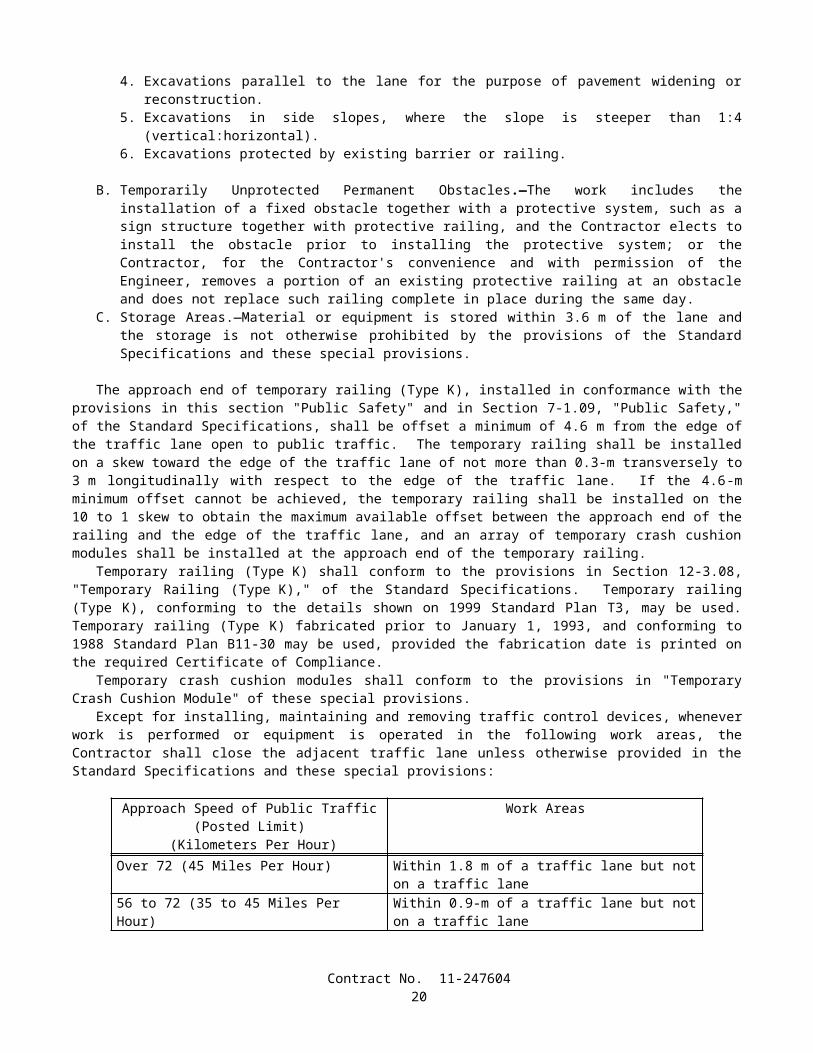
SUBSTITUTION TABLE FOR WIREMETRIC THICKNESS
SHOWN ON THE PLANSmm
WIRE THICKNESSTO BE SUBSTITUTED
inchGAGE NO.
6.20 0.244 35.72 0.225 45.26 0.207 54.88 0.192 64.50 0.177 74.11 0.162 83.76 0.148 93.43 0.135 103.05 0.120 112.69 0.106 122.34 0.092 132.03 0.080 141.83 0.072 151.57 0.062 161.37 0.054 171.22 0.048 181.04 0.041 190.89 0.035 20
SUBSTITUTION TABLE FOR PIPE PILESMETRIC SIZE
SHOWN ON THE PLANSmm x mm
SIZETO BE SUBSTITUTED
inch x inchPP 360 x 4.55 NPS 14 x 0.179PP 360 x 6.35 NPS 14 x 0.250PP 360 x 9.53 NPS 14 x 0.375PP 360 x 11.12 NPS 14 x 0.438PP 406 x 12.70 NPS 16 x 0.500
PP 460 x T NPS 18 x T"PP 508 x T NPS 20 x T"PP 559 x T NPS 22 x T"PP 610 x T NPS 24 x T"PP 660 x T NPS 26 x T"PP 711 x T NPS 28 x T"PP 762 x T NPS 30 x T"PP 813 x T NPS 32 x T"PP 864 x T NPS 34 x T"PP 914 x T NPS 36 x T"PP 965 x T NPS 38 x T"PP 1016 x T NPS 40 x T"PP 1067 x T NPS 42 x T"PP 1118 x T NPS 44 x T"PP 1219 x T NPS 48 x T"PP 1524 x T NPS 60 x T"
The thickness in millimeters (T) represents an exact conversion of the thickness in inches (T").
Contract No. 11-24760421
SUBSTITUTION TABLE FOR STRUCTURAL TIMBER AND LUMBER METRIC MINIMUM
DRESSED DRY,SHOWN ON THE PLANS
mm x mm
METRIC MINIMUM DRESSED GREEN,
SHOWN ON THE PLANSmm x mm
NOMINAL SIZE
TO BE SUBSTITUTEDinch x inch
19x89 20x90 1x438x89 40x90 2x464x89 65x90 3x489x89 90x90 4x4
140x140 143x143 6x6140x184 143x190 6x8184x184 190x190 8x8235x235 241x241 10x10286x286 292x292 12x12
SUBSTITUTION TABLE FOR NAILS AND SPIKESMETRIC COMMON NAIL,SHOWN ON THE PLANS
Length, mmDiameter, mm
METRIC BOX NAIL,SHOWN ON THE PLANS
Length, mmDiameter, mm
METRIC SPIKE,SHOWN ON THE
PLANSLength, mm
Diameter, mm
SIZETO BE
SUBSTITUTEDPenny-weight
50.802.87
50.802.51
______ 6d
63.503.33
63.502.87
______ 8d
76.203.76
76.203.25
76.204.88
10d
82.553.76
82.553.25
82.554.88
12d
88.904.11
88.903.43
88.905.26
16d
101.604.88
101.603.76
101.605.72
20d
114.305.26
114.303.76
114.306.20
30d
127.005.72
127.004.11
127.006.68
40d
______ ______ 139.707.19
50d
______ ______ 152.407.19
60d
Contract No. 11-24760422
SUBSTITUTION TABLE FOR IRRIGATION COMPONENTS
METRICWATER METERS, TRUCK LOADING STANDPIPES, VALVES, BACKFLOW PREVENTERS, FLOW
SENSORS, WYE STRAINERS, FILTER
ASSEMBLY UNITS, PIPE SUPPLY LINES, AND PIPE
IRRIGATION SUPPLY LINES
SHOWN ON THE PLANSDIAMETER NOMINAL
(DN) mm
NOMINAL SIZE
TO BE SUBSTITUTED
inch15 1/220 3/425 132 1-1/440 1-1/250 265 2-1/275 3100 4150 6200 8250 10300 12350 14400 16
Unless otherwise specified, substitutions of United States Standard Measures standard structural shapes corresponding to the metric designations shown on the plans and in conformance with the requirements in ASTM Designation: A 6/A 6M, Annex 2, will be allowed.
8-1.02 PREQUALIFIED AND TESTED SIGNING AND DELINEATION MATERIALSThe Department maintains the following list of Prequalified and Tested Signing and Delineation Materials. The
Engineer shall not be precluded from sampling and testing products on the list of Prequalified and Tested Signing and Delineation Materials.
The manufacturer of products on the list of Prequalified and Tested Signing and Delineation Materials shall furnish the Engineer a Certificate of Compliance in conformance with the provisions in Section 6-1.07, "Certificates of Compliance," of the Standard Specifications for each type of traffic product supplied.
For those categories of materials included in the list of Prequalified and Tested Signing and Delineation Materials, only those products shown within the listing may be used in the work. Other categories of products, not included in the list of Prequalified and Tested Signing and Delineation Materials, may be used in the work provided they conform to the requirements of the Standard Specifications.
Materials and products may be added to the list of Prequalified and Tested Signing and Delineation Materials if the manufacturer submits a New Product Information Form to the New Product Coordinator at the Transportation Laboratory. Upon a Departmental request for samples, sufficient samples shall be submitted to permit performance of required tests. Approval of materials or products will depend upon compliance with the specifications and tests the Department may elect to perform.
Contract No. 11-24760423

PAVEMENT MARKERS, PERMANENT TYPERetroreflective With Abrasion Resistant Surface (ARS)
A. Apex, Model 921AR (100 mm x 100 mm)B. Ray-O-Lite, Model "AA" ARS (100 mm x 100 mm)C. Stimsonite, Models 911 (100 mm x 100 mm) and 953 (70 mm x 114 mm)D. 3M Series 290 (89 mm x 100 mm)
Retroreflective With Abrasion Resistant Surface (ARS)(Used for recessed applications)
A. Stimsonite, Model 948 (58 mm x 119 mm)B. Ray-O-Lite, Model 2002 (58 mm x 117 mm)C. Stimsonite, Model 944SB (51 mm x 100 mm)D. Ray-O-Lite, Model 2004 ARS (51 mm x 100 mm)*
*For use only in 114 mm wide (older) recessed slots
Non-Reflective For Use With Epoxy Adhesive, 100 mm RoundA. Apex Universal (Ceramic)B. Highway Ceramics, Inc. (Ceramic)
Non-Reflective For Use With Bitumen Adhesive, 100 mm RoundA. Alpine Products, "D-Dot" and "ANR" (ABS)B. Apex Universal (Ceramic)C. Apex Universal, Models 929 (ABS) and 929PP (Polypropylene)D. Elgin Molded Plastics, "Empco-Lite" Model 900 (ABS)E. Highway Ceramics, Inc. (Ceramic)F. Hi-Way Safety, Inc., Models P20-2000W and 2001Y (ABS)G. Interstate Sales, "Diamond Back" (ABS) and (Polypropylene)H. Novabrite Models Adot-w (White) Adot-y (Yellow), (ABS)I. Road Creations, Model RCB4NR (Acrylic)J. Zumar Industries, "Titan TM40A" (ABS)
PAVEMENT MARKERS, TEMPORARY TYPETemporary Markers For Long Term Day/Night Use (6 months or less)
A. Apex Universal, Model 924 (100 mm x 100 mm)B. Elgin Molded Plastics, "Empco-Lite" Model 901 (100 mm x 100 mm)C. Road Creations, Model R41C (100 mm x 100 mm)D. Vega Molded Products "Temporary Road Marker" (75 mm x 100 mm)
Temporary Markers For Short Term Day/Night Use (14 days or less)(For seal coat or chip seal applications, clear protective covers are required)
A. Apex Universal, Model 932B. Bunzl (formerly Davidson Plastics, Models) T.O.M., T.R.P.M., and "HH" (High Heat)C. Hi-Way Safety, Inc., Model 1280/1281
STRIPING AND PAVEMENT MARKING MATERIALPermanent Traffic Striping and Pavement Marking Tape
A. Advanced Traffic Marking, Series 300 and 400B. Brite-Line, Series 1000C. Brite-Line, "DeltaLine XRP"D. Swarco Industries, "Director 35" (For transverse application only)E. Swarco Industries, "Director 60"F. 3M, "Stamark" Series 380 and 5730G. 3M, "Stamark" Series 420 (For transverse application only)
Contract No. 11-24760424
Temporary (Removable) Striping and Pavement Marking Tape (6 months or less)A. Advanced Traffic Marking, Series 200B. Brite-Line, Series 100C. P.B. Laminations, Aztec, Grade 102D. Swarco Industries, "Director-2"E. Trelleborg Industri, R140 SeriesF. 3M, Series 620 and Series A750G. 3M, Series A145, Removable Black Line Mask
(Black Tape: for use only on Asphalt Concrete Surfaces)H. Advanced Traffic Marking Black "Hide-A-Line"
(Black Tape: for use only on Asphalt Concrete Surfaces)I. Brite-Line "BTR" Black Removable Tape
(Black Tape: for use only on Asphalt Concrete Surfaces)J. Trelleborg Industri, RB-140
(Black Tape: for use only on Asphalt Concrete Surfaces)
Preformed Thermoplastic (Heated in place)A. Flint Trading, "Premark" and "Premark 20/20 Flex"B. Avery Dennison, "Hotape"
Removable Traffic PaintA. Belpro, Series 250/252 and No. 93 Remover
Ceramic Surfacing Laminate, 150 mm x 150 mmA. Safeline Industries/Highway Ceramics, Inc.
CLASS 1 DELINEATORSOne Piece Driveable Flexible Type, 1700 mm
A. Carsonite, Curve-Flex CFRM-400B. Carsonite, Roadmarker CRM-375C. Bunzl (Formerly Davidson Plastics), "Flexi-Guide Models 400 and 566"D. FlexStake, Model 654 TME. GreenLine Models HWD1-66 and CGD1-66F. J. Miller Industries, Model JMI-375 (with soil anchor)
Special Use Flexible Type, 1700 mmA. Carsonite, "Survivor" (with 450 mm U-Channel base)B. FlexStake, Model 604C. GreenLine Models HWD and CGD (with 450 mm U-Channel base)D. Safe-Hit with 200 mm pavement anchor (SH248-GP1)E. Safe-Hit with 380 mm soil anchor (SH248-GP2) and with 450 mm soil anchor (SH248-GP3)
Surface Mount Flexible Type, 1200 mmA. Bent Manufacturing Company, Masterflex Model MF-180EX-48B. Carsonite, "Super Duck II"C. FlexStake, Surface Mount, Models 704 and 754 TM
CHANNELIZERSSurface Mount Type, 900 mm
A. Bent Manufacturing Company, Masterflex Models MF-360-36 (Round) and MF-180-36 (Flat)B. Carsonite, "Super Duck" (Flat SDF-436, Round SDR-336)C. Carsonite, "Super Duck II" Model SDCF203601MB "The Channelizer"D. Bunzl (Formerly Davidson Plastics), Flex-Guide Models FG300LD and FG300URE. FlexStake, Surface Mount, Models 703 and 753 TMF. GreenLine, Model SMD-36G. Hi-Way Safety, Inc. "Channel Guide Channelizer" Model CGC36
Contract No. 11-24760425

H. The Line Connection, "Dura-Post" Model DP36-3 (Permanent)I. The Line Connection, "Dura-Post" Model DP36-3C (Temporary)J. Repo, Models 300 and 400K. Safe-Hit, Guide Post, Model SH236SMA
CONICAL DELINEATORS, 1070 mm(For 700 mm Traffic Cones, see Standard Specifications)A. Bent Manufacturing Company "T-Top"B. Plastic Safety Systems "Navigator-42"C. Radiator Specialty Company "Enforcer"D. Roadmaker Company "Stacker"E. TrafFix Devices "Grabber"
OBJECT MARKERSType "K", 450 mm
A. Carsonite, Model SMD 615B. FlexStake, Model 701 KMC. Repo, Models 300 and 400D. Safe-Hit, Model SH718SMAE. The Line Connection, Model DP21-4K
Type "K-4" / "Q" Object Markers, 600 mmA. Bent Manufacturing "Masterflex" Model MF-360-24B. Carsonite, Super Duck IIC. FlexStake, Model 701KMD. Repo, Models 300 and 400E. Safe-Hit, Models SH8 24SMA_WA and SH8 24GP3_WAF. The Line Connection, Model DP21-4Q
TEMPORARY RAILING (TYPE K) REFLECTORS AND CONCRETE BARRIER MARKERS
Impactable TypeA. ARTUK, "FB"B. Bunzl (Formerly Davidson Plastics), Model PCBM-12C. Duraflex Corp., "Flexx 2020" and "Electriflexx"D. Hi-Way Safety, Inc., Model GMKRM100
Non-Impactable TypeA. ARTUK, JD SeriesB. Stimsonite, Model 967 (with 83 mm Acrylic cube corner reflector)C. Stimsonite, Model 967LSD. Vega Molded Products, Models GBM and JD
THRIE BEAM BARRIER MARKERS(For use to the left of traffic)A. Duraflex Corp., "Railrider"B. Bunzl (Formerly Davidson Plastics), "Mini" (75 mm x 254 mm)
CONCRETE BARRIER DELINEATORS, 400 mm(For use to the right of traffic. When mounted on top of barrier, place top of reflective element at 1200 mm)A. Bunzl (Formerly Davidson Plastics), Model PCBM T-16B. Safe-Hit, Model SH216RBMC. Sun-Lab Technology, "Safety Guide Light, Model TM," 130 mm x 130 mm x 80 mm
CONCRETE BARRIER-MOUNTED MINI-DRUM (260 mm x 360 mm x 570 mm)A. Stinson Equipment Company "SaddleMarker"
Contract No. 11-24760426
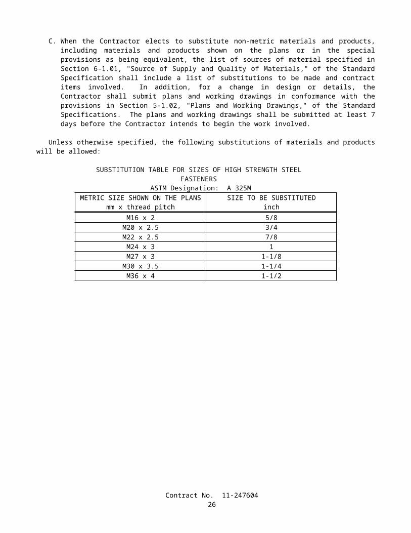
SOUND WALL DELINEATOR(Applied vertically. Place top of 75 mm x 300 mm reflective element at 1200 mm above roadway)A. Bunzl (Formerly Davidson Plastics), PCBM S-36B. Sun-Lab Technology, "Safety Guide Light, Model SM12," 130 mm x 130 mm x 80 mm
GUARD RAILING DELINEATOR(Place top of reflective element at 1200 mm above plane of roadway)
Wood Post Type, 686 mmA. Carsonite, Model 427B. Bunzl (Formerly Davidson Plastics), FG 427 and FG 527C. FlexStake, Model 102 GRD. GreenLine GRD 27E. J.Miller Model JMI-375GF. Safe-Hit, Model SH227GRD
Steel Post TypeA. Carsonite, Model CFGR-327 with CFGRBK300 Mounting Bracket
RETROREFLECTIVE SHEETINGChannelizers, Barrier Markers, and Delineators
A. 3M, High IntensityB. Reflexite, PC-1000 Metalized PolycarbonateC. Reflexite, AC-1000 AcrylicD. Reflexite, AP-1000 Metalized PolyesterE. Reflexite, Conformalight, AR-1000 Abrasion Resistant CoatingF. Avery Dennison T-6500 Series (Formerly Stimsonite, Series 6200) (For rigid substrate devices only)G. Nippon Carbide, Flexible Ultralite Grade (ULG) II
Traffic Cones, 330 mm SleevesA. Reflexite SB (Polyester), Vinyl or "TR" (Semi-transparent)
Traffic Cones, 100 mm and 150 mm SleevesA. 3M Series 3840B. Reflexite Vinyl, "TR" (Semi-transparent) or "Conformalight"C. Nippon Carbide, Flexible Ultralite Grade (ULG) II
Barrels and DrumsA. Reflexite, “Conformalight”, "Super High Intensity" or "High Impact Drum Sheeting"B. 3M Series 3810C. Nippon Carbide, Flexible Ultralite Grade (ULG) IID. Avery Dennison W-6100
Barricades: Type I, Engineer GradeA. American Decal, AdcoliteB. Avery Dennison, T-1500 and T-1600 seriesC. 3M, Engineer Grade, Series 3170
Barricades: Type II, Super Engineer GradeA. Avery Dennison, T-2500 SeriesB. Kiwalite Type IIC. Nikkalite 1800 Series
Signs: Type II, Super Engineer GradeA. Avery Dennison, T-2500 SeriesB. Kiwalite, Type IIC. Nikkalite 1800 Series
Contract No. 11-24760427
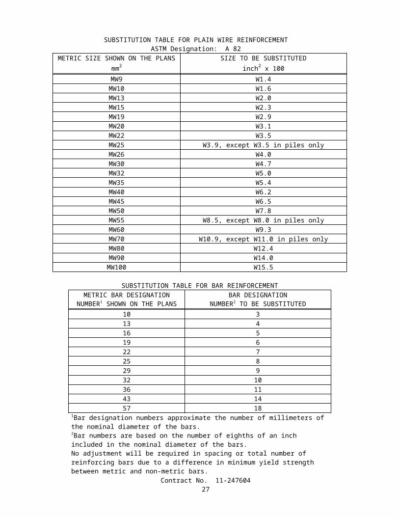
Signs: Type III, High-Intensity GradeA. 3M Series 3800B. Nippon Carbide, Nikkalite Brand Ultralite Grade II
Signs: Type IV, High-Intensity Prismatic GradeA. Avery Dennison T-6500 (Formerly Stimsonite Series 6200)
Signs: Type VII, High-Intensity Prismatic GradeA. 3M Series 3900
Signs: Type VI, Roll-Up SignsA. Reflexite, Vinyl (Orange)B. Reflexite "SuperBright" (Fluorescent orange)C. Reflexite "Marathon" (Fluorescent orange)D. 3M Series RS34 (Orange) and RS20 (Fluorescent orange)
SPECIALTY SIGN (All Plastic)A. All Sign Products, STOP Sign, 750 mm
SIGN SUBSTRATE FOR CONSTRUCTION AREA SIGNSAluminumFiberglass Reinforced Plastic (FRP)
A. Sequentia, "Polyplate"B. Fiber-Brite
8-1.03 STATE-FURNISHED MATERIALSAttention is directed to Section 6-1.02, "State-Furnished Materials," of the Standard Specifications and these special
provisions.
Padlocks for walk gates, and irrigation controller enclosure cabinets will be furnished to the Contractor.
8-1.04 SLAG AGGREGATEAggregate produced from slag resulting from any steel-making process or from air-cooled iron blast furnace slag shall
not be used on this project.
SECTION 8-2. CONCRETE
8-2.01 PORTLAND CEMENT CONCRETEPortland cement concrete shall conform to the provisions in Section 90, "Portland Cement Concrete," of the Standard
Specifications and these special provisions.References to Section 90-2.01, "Portland Cement," of the Standard Specifications shall mean Section 90-2.01, "Cement,"
of the Standard Specifications.Mineral admixture shall be combined with cement in conformance with the provisions in Section 90-4.08, "Required Use
of Mineral Admixtures," of the Standard Specifications for the concrete materials specified in Section 56-2, "Roadside Signs," of the Standard Specifications.
The requirements of Section 90-4.08, "Required Use of Mineral Admixture," of the Standard Specifications shall not apply to Section 19-3.025C, "Soil Cement Bedding," of the Standard Specifications.
The Department maintains a list of sources of fine and coarse aggregate that have been approved for use with a reduced amount of mineral admixture in the total amount of cementitious material to be used. A source of aggregate will be considered for addition to the approved list if the producer of the aggregate submits to the Transportation Laboratory certified test results from a qualified testing laboratory that verify the aggregate complies with the requirements. Prior to starting the testing, the aggregate test shall be registered with the Department. A registration number can be obtained by calling (916) 227-7228. The registration number shall be used as the identification for the aggregate sample in correspondence with the Department. Upon request, a split of the tested sample shall be provided to the Department. Approval of aggregate will depend upon compliance with the specifications, based on the certified test results submitted, together with any replicate
Contract No. 11-24760428
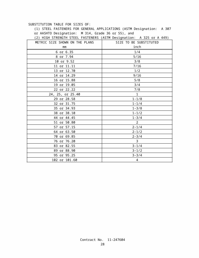
testing the Department may elect to perform. Approval will expire 3 years from the date the most recent registered and evaluated sample was collected from the aggregate source.
Qualified testing laboratories shall conform to the following requirements:
A. Laboratories performing ASTM Designation: C 1293 shall participate in the Cement and Concrete Reference Laboratory (CCRL) Concrete Proficiency Sample Program and shall have received a score of 3 or better on all tests of the previous 2 sets of concrete samples.
B. Laboratories performing ASTM Designation: C 1260 shall participate in the Cement and Concrete Reference Laboratory (CCRL) Pozzolan Proficiency Sample Program and shall have received a score of 3 or better on the shrinkage and soundness tests of the previous 2 sets of pozzolan samples.
Aggregates on the list shall conform to one of the following requirements:
A. When the aggregate is tested in conformance with the requirements in California Test 554 and ASTM Designation: C 1293, the average expansion at one year shall be less than or equal to 0.040 percent; or
B. When the aggregate is tested in conformance with the requirements in California Test 554 and ASTM Designation: C 1260, the average of the expansion at 16 days shall be less than or equal to 0.15 percent.
The amounts of cement and mineral admixture used in cementitious material shall be sufficient to satisfy the minimum cementitious material content requirements specified in Section 90-1.01, "Description," or Section 90-4.05, "Optional Use of Chemical Admixtures," of the Standard Specifications and shall conform to the following:
A. The minimum amount of cement shall not be less than 75 percent by mass of the specified minimum cementitious material content.
B. The minimum amount of mineral admixture to be combined with cement shall be determined using one of the following criteria:
1. When the calcium oxide content of a mineral admixture is equal to or less than 2 percent by mass, the amount of mineral admixture shall not be less than 15 percent by mass of the total amount of cementitious material to be used in the mix.
2. When the calcium oxide content of a mineral admixture is greater than 2 percent by mass, and any of the aggregates used are not listed on the approved list as specified in these special provisions, then the amount of mineral admixture shall not be less than 25 percent by mass of the total amount of cementitious material to be used in the mix.
3. When the calcium oxide content of a mineral admixture is greater than 2 percent by mass and the fine and coarse aggregates are listed on the approved list as specified in these special provisions, then the amount of mineral admixture shall not be less than 15 percent by mass of the total amount of cementitious material to be used in the mix.
4. When a mineral admixture that conforms to the provisions for silica fume in Section 90-2.04, "Admixture Materials," of the Standard Specifications is used, the amount of mineral admixture shall not be less than 10 percent by mass of the total amount of cementitious material to be used in the mix.
5. When a mineral admixture that conforms to the provisions for silica fume in Section 90-2.04, "Admixture Materials," of the Standard Specifications is used and the fine and coarse aggregates are listed on the approved list as specified in these special provisions, then the amount of mineral admixture shall not be less than 7 percent by mass of the total amount of cementitious material to be used in the mix.
C. The total amount of mineral admixture shall not exceed 35 percent by mass of the total amount of cementitious material to be used in the mix. Where Section 90-1.01, "Description," of the Standard Specifications specifies a maximum cementitious content in kilograms per cubic meter, the total mass of cement and mineral admixture per cubic meter shall not exceed the specified maximum cementitious material content.
8-2.02 CEMENT AND WATER CONTENTThe amount of free water used in concrete shall not exceed 201 kg/m3, plus 20 kg for each required 100 kg of cement in
excess of 400 kg/m3.
Contract No. 11-24760429
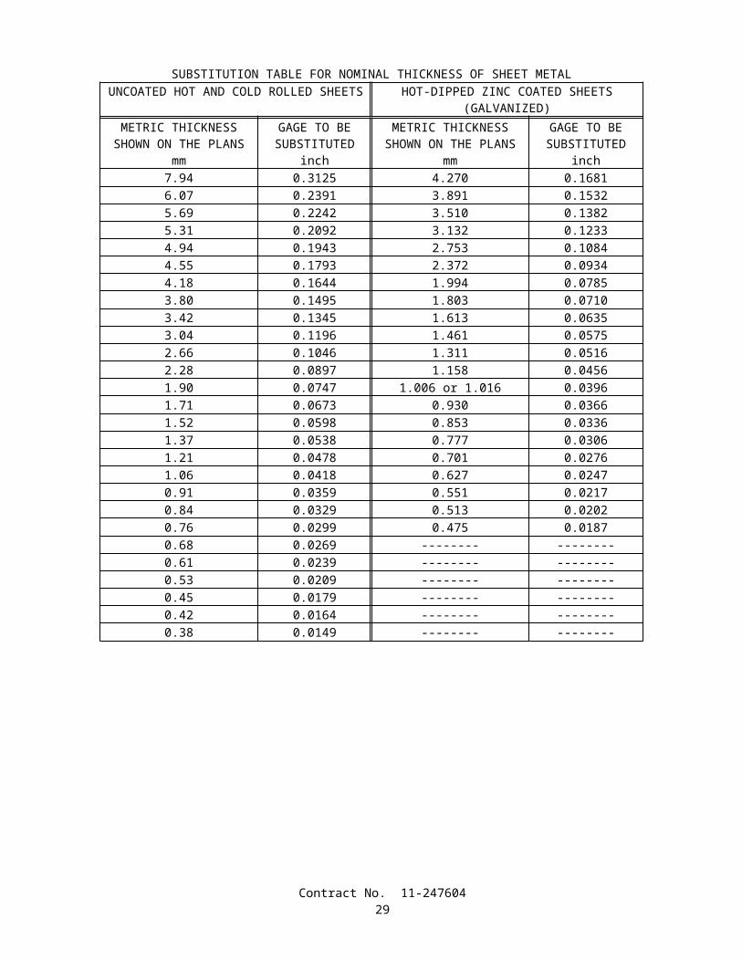
SECTION 8-3. (BLANK)
SECTION 9. (BLANK)
SECTION 10. CONSTRUCTION DETAILS
SECTION 10-1. GENERAL
10-1.01 ORDER OF WORKOrder of work shall conform to the provisions in Section 5-1.05, "Order of Work," of the Standard Specifications and
these special provisions.Fiber rolls shall be installed immediately after roadside clearing has been completed. Attention is directed to "Water
Pollution Control," elsewhere in these special provisions.Within 20 days after the contract has been approved, the Contractor shall furnish the Engineer a statement from the
vendor that the order for the plants required for this contract, including inspection plants, has been received and accepted by the vendor. The statement from the vendor shall include the names, sizes, and quantities of plants ordered and the anticipated date of delivery.
The Contractor shall place orders for replacement plants with the vendor at the appropriate time so that the roots of the replacement plants are not in a root-bound condition.
Attention is directed to Section 9-1.06, "Partial Payments," of the Standard Specifications. For progress payment purposes, the Department will retain 50 percent of the estimated value of highway planting work done until a statement from the vendor that the order for the plants required for this contract has been submitted to the Engineer.
Attention is directed to "Maintain Existing Plants" of these special provisions regarding checking for deficiencies of existing plants that are to remain in place, prior to the start of irrigation work.
Attention is directed to "Irrigation Systems Functional Test" of these special provisions, regarding restrictions for planting operations.
Attention is directed to "Locate Existing Crossovers and Conduits" of these special provisions regarding locating existing irrigation water line crossovers and conduits shown on the plans to be incorporated in the new work. Existing irrigation water line crossovers and conduits shall be located prior to performing work on the irrigation system.
Unless otherwise shown on the plans or specified in these special provisions, conduits to be installed by the open trench method for water line crossovers and sprinkler control crossovers shall be installed prior to the installation of other pipe supply lines.
Attention is directed to "Existing Highway Irrigation Facilities" of these special provisions regarding the checking of existing irrigation facilities that are to remain in place, prior to the start of any irrigation work.
Attention is directed to Section 20-5.027B, "Wiring Plans and Diagrams," of the Standard Specifications regarding submittal of working drawings.
Attention is directed to "Irrigation Controller Enclosure Cabinet" of these special provisions regarding preinstalling irrigation components in the irrigation controller enclosure cabinet prior to field installation.
10-1.02 WATER POLLUTION CONTROLWater pollution control work shall conform to the provisions in Section 7-1.01G, "Water Pollution," of the Standard
Specifications and these special provisions.Water pollution control work shall conform to the requirements in the "Storm Water Pollution Prevention Plan (SWPPP)
and Water Pollution Control Program (WPCP) Preparation Manual" and the "Construction Site Best Management Practices (BMPs) Manual," and addenda thereto issued up to, and including, the date of advertisement of the project, hereafter referred to respectively as the "Preparation Manual" and the "Construction Site BMP Manual" and collectively as the "Manuals." Copies of the Manuals may be obtained from the Department of Transportation, Material Operations Branch, Publication Distribution Unit, 1900 Royal Oaks Drive, Sacramento, California 95815, Telephone: (916) 445-3520. Copies of the Manuals may also be obtained from the Department's Internet Web Site at: http://www.dot.ca.gov/hq/construc/stormwater.html.
Copies of the Manuals are also available for review at Caltrans District Office, District Construction Liaison Office, 2829 Juan Street, San Diego, California 92110, Telephone (619) 688-6635..
The Contractor shall know and fully comply with the applicable provisions of the Manuals and Federal, State, and local regulations that govern the Contractor's operations and storm water discharges from both the project site and areas of disturbance outside the project limits during construction.
Contract No. 11-24760430
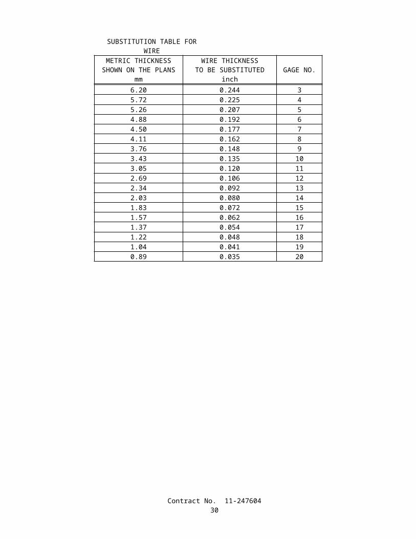
Unless arrangements for disturbance of areas outside the project limits are made by the Department and made part of the contract, it is expressly agreed that the Department assumes no responsibility whatsoever to the Contractor or property owner with respect to any arrangements made between the Contractor and property owner to allow disturbance of areas outside the project limits.
The Contractor shall be responsible for the costs and for liabilities imposed by law as a result of the Contractor's failure to comply with the requirements set forth in this section "Water Pollution Control" including, but not limited to, compliance with the applicable provisions of the Manuals and Federal, State, and local regulations. For the purposes of this paragraph, costs and liabilities include, but are not limited to, fines, penalties, and damages whether assessed against the State or the Contractor, including those levied under the Federal Clean Water Act and the State Porter Cologne Water Quality Act.
In addition to the remedies authorized by law, an amount of the money due the Contractor under the contract, as determined by the Department, may be retained by the State of California until disposition has been made of the costs and liabilities.
The retention of money due the Contractor shall be subject to the following:
A. The Department will give the Contractor 30 days notice of the Department's intention to retain funds from partial payments which may become due to the Contractor prior to acceptance of the contract. Retention of funds from payments made after acceptance of the contract may be made without prior notice to the Contractor.
B. No retention of additional amounts out of partial payments will be made if the amount to be retained does not exceed the amount being withheld from partial payments pursuant to Section 9-1.06, "Partial Payments," of the Standard Specifications.
C. If the Department has retained funds and it is subsequently determined that the State is not subject to the costs and liabilities in connection with the matter for which the retention was made, the Department shall be liable for interest on the amount retained at the legal rate of interest for the period of the retention.
Conformance with the provisions in this section "Water Pollution Control" shall not relieve the Contractor from the Contractor's responsibilities as provided in Section 7, "Legal Relations and Responsibilities," of the Standard Specifications.
WATER POLLUTION CONTROL PROGRAM PREPARATION, APPROVAL AND UPDATESAs part of the water pollution control work, a Water Pollution Control Program, hereafter referred to as the "WPCP," is
required for this contract. The WPCP shall conform to the provisions in Section 7-1.01G, "Water Pollution," of the Standard Specifications, the requirements in the Manuals, and these special provisions.
No work having potential to cause water pollution, as determined by the Engineer, shall be performed until the WPCP has been approved by the Engineer.
Within 15 days after the approval of the contract, the Contractor shall submit 5 copies of the WPCP to the Engineer. The Engineer will have 7 days to review the WPCP. If revisions are required, as determined by the Engineer, the Contractor shall revise and resubmit the WPCP within 3 days of receipt of the Engineer's comments. The Engineer will have 3 days to review the revisions. Upon the Engineer's approval of the WPCP, 3 additional copies of the WPCP incorporating the required changes shall be submitted to the Engineer. Minor changes or clarifications to the initial submittal may be made and attached as amendments to the WPCP. In order to allow construction activities to proceed, the Engineer may conditionally approve the WPCP while minor revisions or amendments are being completed.
The WPCP shall identify pollution sources that may adversely affect the quality of storm water discharges associated with the project and shall identify water pollution control measures, hereafter referred to as control measures, to be constructed, implemented, and maintained in order to reduce to the extent feasible pollutants in storm water discharges from the construction site during construction under this contract.
The WPCP shall incorporate control measures in the following categories:
A. Soil stabilization;B. Sediment control;C. Tracking control;D. Wind erosion control;E. Non-storm water control; andF. Waste management and material pollution control.
Specific objectives and minimum requirements for each category of control measures are contained in the Manuals.The Contractor shall consider the objectives and minimum requirements presented in the Manuals for each of the above
categories. When minimum requirements are listed for any category, the Contractor shall incorporate into the WPCP and implement on the project, one or more of the listed minimum controls required in order to meet the pollution control objectives for the category. In addition, the Contractor shall consider other control measures presented in the Manuals and
Contract No. 11-24760431

shall incorporate into the WPCP and implement on the project the control measures necessary to meet the objectives of the WPCP. The Contractor shall document the selection process in conformance with the procedure specified in the Manuals.
The following contract items of work shall be incorporated into the WPCP as critical temporary control measures: temporary gravel bag and temporary concrete washout. The Contractor shall consider other control measures to supplement these critical temporary control measures when necessary to meet the pollution control objectives of the WPCP.
The following contract items of work, as shown on the project plans, shall be incorporated in the WPCP as permanent post-construction control measures: fiber rolls. These control measures shall be utilized as construction period control measures. Attention is directed to "Order of Work" of these special provisions. The Contractor shall consider other control measures to supplement these permanent, post-construction control measures when necessary to meet the pollution control objectives of the WPCP. The Contractor shall maintain and protect the permanent control measures throughout the duration of the project and shall restore these controls to the lines and grades shown on the plans prior to acceptance of the project.
The WPCP shall include, but not be limited to, the following items as described in the Preparation Manual:
A. Project description and Contractor's certification;B. Project information;C. Pollution sources, control measures, and water pollution control drawings; andD. Amendments, if any.
The Contractor shall amend the WPCP, graphically and in narrative form, whenever there is a change in construction activities or operations which may affect the discharge of significant quantities of pollutants to surface waters, ground waters, municipal storm drain systems or when deemed necessary by the Engineer. The WPCP shall be amended if the WPCP has not achieved the objective of reducing pollutants in storm water discharges. Amendments shall show additional control measures or revised operations, including those in areas not shown in the initially approved WPCP, which are required on the project to control water pollution effectively. Amendments to the WPCP shall be submitted for review and approval by the Engineer in the same manner specified for the initially approved WPCP. Amendments shall be dated and attached to the on-site WPCP document.
The Contractor shall keep a copy of the WPCP, together with updates, revisions and amendments at the project site.
WPCP IMPLEMENTATIONUpon approval of the WPCP, the Contractor shall be responsible throughout the duration of the project for installing,
constructing, inspecting, and maintaining the control measures included in the WPCP and any amendments thereto and for removing and disposing of temporary control measures. Unless otherwise directed by the Engineer or specified in these special provisions, the Contractor's responsibility for WPCP implementation shall continue throughout any temporary suspension of work ordered in conformance with the provisions in Section 8-1.05, "Temporary Suspension of Work," of the Standard Specifications. Requirements for installation, construction, inspection, maintenance, removal, and disposal of control measures are specified in the Manuals and these special provisions.
Soil stabilization practices and sediment control measures, including minimum requirements, shall be provided throughout the rainy season, defined as between October 1 and May 1.
Implementation of soil stabilization practices and sediment control measures for soil-disturbed areas on the project site shall be completed, except as provided for below, not later than 20 days prior to the beginning of the rainy season or upon start of applicable construction activities for projects which begin either during or within 20 days of the rainy season.
Throughout the rainy season, the active, soil-disturbed area of the project site shall be not more than 1.95 hectares. The Engineer may approve, on a case-by-case basis, expansions of the active, soil-disturbed area limit. The Contractor shall demonstrate the ability and preparedness to fully deploy soil stabilization practices and sediment control measures to protect soil-disturbed areas on the project site before the onset of precipitation. A quantity of soil stabilization and sediment control materials shall be maintained on site equal to 100 percent of that sufficient to protect unprotected, soil-disturbed areas on the project site. A detailed plan for the mobilization of sufficient labor and equipment shall be maintained to fully deploy control measures required to protect unprotected, soil-disturbed areas on the project site prior to the onset of precipitation. A current inventory of control measure materials and the detailed mobilization plan shall be included as part of the WPCP.
Throughout the rainy season, soil-disturbed areas on the project site shall be considered to be nonactive whenever soil disturbing activities are expected to be discontinued for a period of 20 or more days and the areas are fully protected. Areas that will become nonactive either during the rainy season or within 20 days thereof shall be fully protected with soil stabilization practices and sediment control measures within 10 days of the discontinuance of soil disturbing activities or prior to the onset of precipitation, whichever is first to occur.
Throughout the rainy season, active soil-disturbed areas of the project site shall be fully protected at the end of each day with soil stabilization practices and sediment control measures unless fair weather is predicted through the following work day. The weather forecast shall be monitored by the Contractor on a daily basis. The National Weather Service forecast
Contract No. 11-24760432

shall be used. An alternative weather forecast proposed by the Contractor may be used if approved by the Engineer. If precipitation is predicted prior to the end of the following work day, construction scheduling shall be modified, as required, and functioning control measures shall be deployed prior to the onset of the precipitation.
The Contractor shall implement, year-round and throughout the duration of the project, control measures included in the WPCP for tracking control, wind erosion control, non-storm water control, and waste management and material pollution control.
The Engineer may order the suspension of construction operations which create water pollution if the Contractor fails to conform to the provisions in this section "Water Pollution Control" as determined by the Engineer.
MAINTENANCETo ensure the proper implementation and functioning of control measures, the Contractor shall regularly inspect and
maintain the construction site for the control measures identified in the WPCP. The Contractor shall identify corrective actions and time needed to address any deficient measures or reinitiate any measures that have been discontinued.
The construction site inspection checklist provided in the Preparation Manual shall be used to ensure that the necessary measures are being properly implemented, and to ensure that the control measures are functioning adequately. One copy of each site inspection record shall be submitted to the Engineer.
During the rainy season, inspections of the construction site shall be conducted by the Contractor to identify deficient measures, as follows:
A. Prior to a forecast storm;B. After all precipitation which causes runoff capable of carrying sediment from the construction site;C. At 24-hour intervals during extended precipitation events; andD. Routinely, at a minimum of once every 2 weeks.
If the Contractor or the Engineer identifies a deficiency in the deployment or functioning of an identified control measure, the deficiency shall be corrected immediately. The deficiency may be corrected at a later date and time if requested by the Contractor and approved by the Engineer in writing, but not later than the onset of subsequent precipitation events. The correction of deficiencies shall be at no additional cost to the State.
WATER POLLUTION CONTROL TRAININGThe Contractor's management and supervisory personnel along with workers involved with the placement and
maintenance of storm water pollution prevention "Best Management Practices" shall be trained on general storm water pollution control requirements consistent with the "Construction Site Best Management Practices (BMPs) Manual". The training is to be provided by the Contractor. The amount of training provided should be commensurate with the job performed by the employee.
PAYMENTFull compensation for conforming to the provisions in this section shall be considered as included in the prices paid for
the various contract items of work involved and no additional compensation will be allowed therefor.Those control measures for which there is a contract item of work will be measured and paid for as that contract item of
work.The Engineer will retain an amount equal to 25 percent of the estimated value of the contract work performed during
estimate periods in which the Contractor fails to conform to the provisions in this section "Water Pollution Control" as determined by the Engineer.
Retentions for failure to conform to the provisions in this section "Water Pollution Control" shall be in addition to the other retentions provided for in the contract. The amounts retained for failure of the Contractor to conform to the provisions in this section will be released for payment on the next monthly estimate for partial payment following the date that a WPCP has been implemented and maintained and water pollution is adequately controlled, as determined by the Engineer.
10-1.03 PRESERVATION OF PROPERTYAttention is directed to Section 7-1.11, "Preservation of Property," of the Standard Specifications and these special
provisions.Existing trees, shrubs and other plants, that are not to be removed as shown on the plans or specified in these special
provisions, and are injured or damaged by reason of the Contractor's operations, shall be replaced by the Contractor. The minimum size of tree replacement shall be 600 mm box and the minimum size of shrub replacement shall be No. 15 container. Replacement ground cover plants shall be from flats and shall be planted 300 mm on center. Replacement of Carpobrotus ground cover plants shall be from cuttings and shall be planted 300 mm on center. Replacement planting shall
Contract No. 11-24760433

conform to the requirements in Section 20-4.07, "Replacement," of the Standard Specifications. The Contractor shall water replacement plants in conformance with the provisions in Section 20-4.06, "Watering," of the Standard Specifications.
Damaged or injured plants shall be removed and disposed of outside the highway right of way in conformance with the provisions in Section 7-l.13 of the Standard Specifications. At the option of the Contractor, removed trees and shrubs may be reduced to chips. The chipped material shall be spread within the highway right of way at locations designated by the Engineer.
Replacement planting of injured or damaged trees, shrubs, and other plants shall be completed prior to the start of the plant establishment period. Replacement planting shall conform to the provisions in Section 20-4.05, "Planting," of the Standard Specifications.
10-1.04 TEMPORARY GRAVEL BAGTemporary gravel bag shall conform to the details shown on the plans and these special provisions.Temporary gravel bag shall be furnished, installed, maintained and removed at the locations shown on the plans.Preparation shall conform to the provisions in Section 20-3.02, "Preparation," of the Standard Specifications.Attention is directed to "Water Pollution Control" of these special provisions.
MATERIALSMaterials shall conform to the provisions in Section 20-2, "Materials," of the Standard Specifications.Gravel bag fabric shall be woven polypropylene, polyethylene or Polyamide with a minimum unit weight of 135 g/m2.
The fabric shall have a mullen burst strength of at least 2067 kPa, conforming to the requirements in ASTM Designation: D 3786 and an ultraviolet (UV) stability exceeding 70 percent.
Gravel bags, when filled, shall have nominal dimensions (length x width x height) of 400 mm x 300 mm x 150 mm, and a filled mass of 13 kg to 22 kg.
Gravel bag fill material shall be non-cohesive gravel, free from deleterious material.
INSTALLATIONTemporary gravel bags placed in multiple layers shall be installed as shown on the plans and in conformance with
Section 4, detail SC 8 in the Construction Site Best Management Practices (BMPs) Manual of the Caltrans Storm Water Quality Handbooks.
Temporary gravel bag shall be maintained to provide for adequate sediment holding capacity. Sediment deposits shall be removed when the deposit reaches one-third of the temporary gravel bag barrier height. Removed sediment shall be deposited within the project in such a way that the sediment is not subject to erosion by wind or water, or as directed by the Engineer.
When no longer required for the intended purpose, as determined by the Engineer, temporary gravel bag shall be removed from the site of the work.
Holes, depressions or any other ground disturbance caused by the removal of the temporary gravel bag shall be backfilled and repaired in conformance with the provisions in the second paragraph of Section 15-1.02, "Preservation of Property," of the Standard Specifications.
MEASUREMENT AND PAYMENTTemporary gravel bags will be measured by the unit as determined from actual count in place.The contract unit price paid for temporary gravel bag shall include full compensation for furnishing all labor, materials,
tools, equipment, and incidentals, and for doing all the work involved in installing temporary gravel bag barriers complete in place, including maintenance and removal of materials, as shown on the plans, as specified in the Standard Specifications and these special provisions, and as directed by the Engineer.
Temporary gravel bag placed at locations other than as shown on the project plans or directed by the Engineer, in accordance with the Contractor's Storm Water Pollution Prevention Plan, will not be measured and will be paid for as specified in "Water Pollution Control" of these special provisions.
No adjustment of compensation will be made for any increase or decrease in the quantities of temporary gravel bags required, regardless of the reason for the increase or decrease. The provisions in Section 4-1.03B, "Increased or Decreased Quantities," of the Standard Specifications shall not apply to temporary gravel bags.
10-1.05 TEMPORARY CONCRETE WASHOUTTemporary concrete washout shall be constructed, maintained, and later removed as shown on the plans, as specified in
these special provisions, and as directed by the Engineer.Attention is directed to "Water Pollution Control" elsewhere in these special provisions.
Contract No. 11-24760434

Temporary concrete washout shall be located a minimum of 15 meters from downstream storm drain inlets, open drainage facilities, and watercourses. Each facility shall be located away from construction traffic or access areas to prevent disturbance or tracking. The exact location of the temporary concrete washout will be determined by the Engineer.
A sign shall be erected as shown on the plans. The perimeter of the concrete washout shall be delineated by lath and flagging to prevent accidental access.
Plastic lining shall have a minimum thickness of 12 mils, and shall be firmly held in place with Gravel bags placed no more than one meter apart. Plastic lining shall be installed and maintained in accordance with the manufacturers instructions.
Gravel bags shall conform with the provisions for "Temporary Gravel Bag" elsewhere in these special provisions.Maintaining temporary concrete washout shall include removing and disposing of hardened concrete. Concrete waste
materials shall be removed and disposed of in conformance with the provisions in Section 15-3.02, "Removal Methods," of the Standard Specifications.
When temporary concrete washout is no longer required for the work, as determined by the Engineer, the concrete waste shall be removed and disposed of in conformance with the provisions in Section 15-3.02, "Removal Methods," of the Standard Specifications. Materials for temporary concrete washout shall become the property of the Contractor and shall be removed from the site of the work and disposed of outside of the highway right of way in accordance with section 7-1.13, "Disposal of Material Outside the Highway Right of Way" of the Standard Specifications.
Trenches, depressions and pits caused by the removal of temporary concrete washout shall be backfilled in accordance with the provisions in the second paragraph of Section 15-1.02, "Preservation of Property," of the Standard Specifications..
Temporary concrete washout will be measured and paid for by the unit from actual count.The contract unit price paid for temporary concrete washout shall include full compensation for furnishing all labor,
materials, tools, equipment, and incidentals, and for doing all the work involved in constructing temporary concrete washout, complete in place, including temporary gravel bags, excavation, backfill and plastic lining, (maintaining), removing and disposing of concrete waste and temporary concrete washout as shown on the plans, as specified in the Standard Specifications and these special provisions, and as directed by the Engineer.
10-1.06 COOPERATIONAttention is directed to Section 7-1.14, "Cooperation," and Section 8-1.10, "Utility and Non-Highway Facilities," of the
Standard Specifications and these special provisions.It is anticipated that work by another contractor (Contract No. 11-172834) to construct freeway in San Diego on
Route 56 from 0.1 km west to 0.7 km East of Black Mountain Rd. (KP 10.1 to KP 11.9), may be in progress adjacent to or within the limits of this project during progress of the work on this contract.
Consecutive on-ramp or off-ramps in the same direction of travel shall not be closed simultaneously unless otherwise provided in these special provisions or permitted by the Engineer.
10-1.07 PROGRESS SCHEDULEProgress schedules are required for this contract and shall be submitted in conformance with the provisions in
Section 8-1.04, "Progress Schedule," of the Standard Specifications and these special provisions, unless otherwise authorized in writing by the Engineer.
The second paragraph of Section 8-1.04, "Progress Schedule," of the Standard Specifications shall not apply.
10-1.08 OBSTRUCTIONSAttention is directed to Section 8-1.10, "Utility and Non-Highway Facilities," and Section 15, "Existing Highway
Facilities," of the Standard Specifications and these special provisions.Attention is directed to the existence of certain underground facilities that may require special precautions be taken by
the Contractor to protect the health, safety and welfare of workers and of the public. Facilities requiring special precautions include, but are not limited to: conductors of petroleum products, oxygen, chlorine, and toxic or flammable gases; natural gas in pipelines greater than 150 mm in diameter or pipelines operating at pressures greater than 415 kPa (gage); underground electric supply system conductors or cables, with potential to ground of more than 300 V, either directly buried or in a duct or conduit which do not have concentric grounded or other effectively grounded metal shields or sheaths.
The Contractor shall notify the Engineer and the appropriate regional notification center for operators of subsurface installations at least 2 working days, but not more than 14 calendar days, prior to performing any excavation or other work close to any underground pipeline, conduit, duct, wire or other structure. Regional notification centers include, but are not limited to, the following:
Contract No. 11-24760435
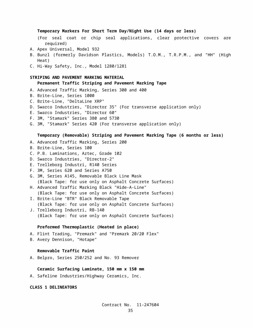
Notification Center Telephone NumberUnderground Service Alert-Northern California (USA) 1-800-642-2444
1-800-227-2600Underground Service Alert-Southern California (USA) 1-800-422-4133
1-800-227-2600
No excavation shall be performed within 1.2 m (4 feet) of the following utilities until the owner, or the owner's representative has located the facility by pot holing, probing, or other means that will positively locate and identify the facility both horizontally and vertically. The utility company will be allowed 20 working days to perform this work.
The utility owner or the owner's representative shall be present whenever any excavation is performed within 1.2 meters of the following utilities.
Owner Type LocationSDG&E 200 mm gas main Rancho Penasquitos Bl. UCSDG&E 400 mm gas main Crossing SR 56 at Station 161+30SDG&E U/G Electric line Rancho Penasquitos Bl. UCSDG&E 100 mm gas line Rancho Penasquitos Bl. UC
10-1.09 MOBILIZATIONMobilization shall conform to the provisions in Section 11, "Mobilization," of the Standard Specifications.
10-1.10 CONSTRUCTION AREA TRAFFIC CONTROL DEVICES Flagging, signs, and all other traffic control devices furnished, installed, maintained, and removed when no longer
required shall conform to the provisions in Section 12, "Construction Area Traffic Control Devices," of the Standard Specifications and these special provisions.
Category 1 traffic control devices are defined as those devices that are small and lightweight (less than 45 kg), and have been in common use for many years. The devices shall be known to be crashworthy by crash testing, crash testing of similar devices, or years of demonstrable safe performance. Category 1 traffic control devices include traffic cones, plastic drums, portable delineators, and channelizers.
If requested by the Engineer, the Contractor shall provide written self-certification for crashworthiness of Category 1 traffic control devices. Self-certification shall be provided by the manufacturer or Contractor and shall include the following: date, Federal Aid number (if applicable), expenditure authorization, district, county, route and kilometer post of project limits; company name of certifying vendor, street address, city, state and zip code; printed name, signature and title of certifying person; and an indication of which Category 1 traffic control devices will be used on the project. The Contractor may obtain a standard form for self-certification from the Engineer.
Category 2 traffic control devices are defined as those items that are small and lightweight (less than 45 kg), that are not expected to produce significant vehicular velocity change, but may otherwise be potentially hazardous. Category 2 traffic control devices include: barricades and portable sign supports.
Category 2 devices purchased on or after October 1, 2000 shall be on the Federal Highway Administration (FHWA) Acceptable Crashworthy Category 2 Hardware for Work Zones list. This list is maintained by FHWA and can be located at the following internet address: http://safety.fhwa.dot.gov/fourthlevel/hardware/listing.cfm?code=workzone. The Department maintains a secondary list at the following internet address: http://www.dot.ca.gov/hq/traffops/signtech/signdel/pdffiles.htm.
Category 2 devices that have not received FHWA acceptance, and were purchased before October 1, 2000, may continue to be used until they complete their useful service life or until January 1, 2003, whichever comes first. Category 2 devices in use that have received FHWA acceptance shall be labeled with the FHWA acceptance letter number and the name of the manufacturer by the start of the project. The label shall be readable. After January 1, 2003, all Category 2 devices without a label shall not be used on the project.
Full compensation for providing self-certification for crashworthiness of Category 1 traffic control devices and labeling Category 2 devices as specified shall be considered as included in the prices paid for the various contract items of work requiring the use of the Category 1 or Category 2 traffic control devices and no additional compensation will be allowed therefor.
10-1.11 CONSTRUCTION AREA SIGNSConstruction area signs shall be furnished, installed, maintained, and removed when no longer required in conformance
with the provisions in Section 12, "Construction Area Traffic Control Devices," of the Standard Specifications and these special provisions.
Contract No. 11-24760436

Attention is directed to the provisions in "Prequalified and Tested Signing and Delineation Materials" of these special provisions. Type II retroreflective sheeting shall not be used on construction area sign panels.
The Contractor shall notify the appropriate regional notification center for operators of subsurface installations at least 2 working days, but not more than 14 calendar days, prior to commencing excavation for construction area sign posts. The regional notification centers include, but are not limited to, the following:
Notification Center Telephone NumberUnderground Service Alert-Northern California (USA) 1-800-642-2444
1-800-227-2600Underground Service Alert-Southern California (USA) 1-800-422-4133
1-800-227-2600
Excavations required to install construction area signs shall be performed by hand methods without the use of power equipment, except that power equipment may be used if it is determined there are no utility facilities in the area of the proposed post holes.
Sign substrates for stationary mounted construction area signs may be fabricated from fiberglass reinforced plastic as specified under "Prequalified and Tested Signing and Delineation Materials" of these special provisions.
10-1.12 MAINTAINING TRAFFICAttention is directed to Sections 7-1.08, "Public Convenience," 7-1.09, "Public Safety," and 12, "Construction Area
Traffic Control Devices," of the Standard Specifications and to the provisions in "Public Safety" of these special provisions and these special provisions. Nothing in these special provisions shall be construed as relieving the Contractor from the responsibilities specified in Section 7-1.09.
Attention is directed to "Traffic Plastic Drums," elsewhere in these special provisions regarding the use of plastic drums in place of portable delineators, cones or Type I or II barricades.
Lane closures shall conform to the provisions in section "Traffic Control System for Lane Closure" of these special provisions.
Personal vehicles of the Contractor's employees shall not be parked on the traveled way or shoulders including any section closed to public traffic.
Whenever vehicles or equipment are parked on the shoulder within 1.8 m of a traffic lane, the shoulder area shall be closed as shown on the plans.
Lanes shall be closed only during the hours shown on the charts included in this section "Maintaining Traffic." Except work required under Sections 7-1.08 and 7-1.09, work that interferes with public traffic shall be performed only during the hours shown for lane closures.
The full width of the traveled way shall be open for use by public traffic on when construction operations are not actively in progress.
Designated legal holidays are: January 1st, the third Monday in February, the last Monday in May, July 4th, the first Monday in September, November 11th, Thanksgiving Day, and December 25th. When a designated legal holiday falls on a Sunday, the following Monday shall be a designated legal holiday. When November 11th falls on a Saturday, the preceding Friday shall be a designated legal holiday.
Minor deviations from the requirements of this section concerning hours of work which do not significantly change the cost of the work may be permitted upon the written request of the Contractor, if in the opinion of the Engineer, public traffic will be better served and the work expedited. These deviations shall not be adopted by the Contractor until the Engineer has approved the deviations in writing. All other modifications will be made by contract change order.
Contract No. 11-24760437
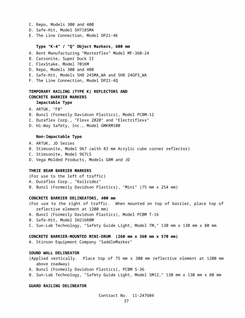
Chart No. 1Multilane Lane Requirements
Direction: Eastbound SD - 56 Location: 0.20 km W. of Rancho Penasquito Blvd. to JCT RTE 15
a.m. p.m.FROM HOUR TO HOUR 12 1 2 3 4 5 6 7 8 9 10 11 12 1 2 3 4 5 6 7 8 9 10 11 12Mondays through Thursdays 1 1 1 1 1 1 1 1 1 1 1 1 1
Fridays 1 1 1 1 1 1 1 1 1Saturdays 1 1 1 1 1 1Sundays 1 1 1 1 1 1 1 1 1 1
Day before designated legal holiday 1 1 1 1 1Designated legal holidays
Legend:1 One lane open in direction of travel
No lane closure allowed
REMARKS:
KP: 12.74 / 14.82F=247604041701PK
Chart No. 2Multilane Lane Requirements
Direction: Westbound SD - 56 Location: 0.20 km W. of Rancho Penasquito Blvd. to JCT RTE 15
a.m. p.m.FROM HOUR TO HOUR 12 1 2 3 4 5 6 7 8 9 10 11 12 1 2 3 4 5 6 7 8 9 10 11 12Mondays through Thursdays 1 1 1 1 1 1 1 1 1 1 1 1 1 1 1
Fridays 1 1 1 1 1 1 1 1 1 1 1Saturdays 1 1 1 1 1 1 1 1 1Sundays 1 1 1 1 1 1 1 1 1 1 1 1
Day before designated legal holiday 1 1 1 1 1 1 1 1 1 1 1Designated legal holidays
Legend:1 One lane open in direction of travel
No lane closure allowed
REMARKS:
KP: 12.74 / 14.82F=247604041701PK
Contract No. 11-24760438

Chart No. 3Shoulder Closure Requirements
Direction: Eastbound - Westbound SD - 56 Location: 0.20 km W. of Rancho Penasquito Blvd. to JCT RTE 15
a.m. p.m.FROM HOUR TO HOUR 12 1 2 3 4 5 6 7 8 9 10 11 12 1 2 3 4 5 6 7 8 9 10 11 12Mondays through Thursdays S S S S S S S S
Fridays S S S S S S S SSaturdays S S S S S S S S S SSundays S S S S S S S S S S
Day before designated legal holiday S S S S S S S SDesignated legal holidays
Legend:S Shoulder may be closed
No lane closure allowed
REMARKS:
KP: 12.74 / 14.82F= 247604041701PK
Chart No. 4 Street Requirements
Direction: Northbound – Southbound "Rancho Penasquitos Blvd."
Location: At RTE 56
a.m. p.m.FROM HOUR TO HOUR 12 1 2 3 4 5 6 7 8 9 10 11 12 1 2 3 4 5 6 7 8 9 10 11 12Mondays through Thursdays 1 1 1 1 1 1 1 1 1 1 1 1 1 1
Fridays 1 1 1 1 1 1 1 1 1 1 1SaturdaysSundays 1 1 1
Day before designated legal holiday 1 1 1 1 1Designated legal holidays
Legend:1 One lane open in direction of travel
No work that interferes with public traffic will be allowed
REMARKS:
NOTE:
KP: 12.94
F=247604041701PK
Contract No. 11-24760439
10-1.13 CLOSURE REQUIREMENTS AND CONDITIONSLane closures shall conform to the provisions in "Maintaining Traffic" of these special provisions and these special
provisions.The term closure, as used herein, is defined as the closure of a traffic lane or lanes, including ramp or connector lanes,
within a single traffic control system.
CLOSURE SCHEDULEBy noon Monday, the Contractor shall submit a written schedule of planned closures for the following week period,
defined as Friday noon through the following Friday noon.The Closure Schedule shall show the locations and times when the proposed closures are to be in effect. The Contractor
shall use the Closure Schedule request forms furnished by the Engineer. Closure Schedules submitted to the Engineer with incomplete, unintelligible or inaccurate information will be returned for correction and resubmittal. The Contractor will be notified of disapproved closures or closures that require coordination with other parties as a condition of approval.
CONTINGENCY PLAN The Contractor shall prepare a contingency plan for reopening closures to public traffic. The Contractor shall submit the
contingency plan for a given operation to the Engineer within one working day of the Engineer's request.
LATE REOPENING OF CLOSURESIf a closure is not reopened to public traffic by the specified time, work shall be suspended in conformance with the
provisions in Section 8-1.05, "Temporary Suspension of Work," of the Standard Specifications. The Contractor shall not make any further closures until the Engineer has accepted a work plan, submitted by the Contractor, that will insure that future closures will be reopened to public traffic at the specified time. The Engineer will have 2 working days to accept or reject the Contractor's proposed work plan. The Contractor will not be entitled to any compensation for the suspension of work resulting from the late reopening of closures.
COMPENSATIONThe Contractor shall notify the Engineer of any delay in the Contractor's operations due to the following conditions, and
if, in the opinion of the Engineer, the Contractor's controlling operation is delayed or interfered with by reason of those conditions, and the Contractor's loss due to that delay could not have been avoided by rescheduling the affected closure or by judicious handling of forces, equipment and plant, the delay will be considered a right of way delay within the meaning of Section 8-1.09, "Right of Way Delays," and compensation for the delay will be determined in conformance with the provisions in Section 8-1.09:
A. The Contractor's proposed Closure Schedule is denied and his planned closures are within the time frame allowed for closures in "Maintaining Traffic" of these special provisions, except that the Contractor will not be entitled to any compensation for amendments to the Closure Schedule that are not approved.
B. The Contractor is denied a confirmed closure.
Should the Engineer direct the Contractor to remove a closure prior to the time designated in the approved Closure Schedule, any delay to the Contractor's schedule due to removal of the closure will be considered a right of way delay within the meaning of Section 8-1.09, "Right of Way Delays," and compensation for the delay will be determined in conformance with the provisions in Section 8-1.09.
10-1.14 CONSTRUCTION ZONE ENHANCED ENFORCEMENTConstruction zone enhanced enforcement will be provided by the State as directed by the Engineer and in conformance
with these special provisions. Construction zone enhanced enforcement shall consist of the presence of the California Highway Patrol (CHP) within and near the limits of construction during specified stages of work to control the movement of public traffic within the work zone. A total of 180 hours of California Highway Patrol support is available.
Contract No. 11-24760440
The Contractor may request additional CHP support for other times and in support of other work activities. The Contractor shall bear the costs and expenses for additional CHP support. The CHP shall be compensated at an agreed rate of $55 per hour per CHP Officer. The agreed rate shall be considered full compensation for each hour, or portion thereof, that a CHP Officer is performing construction area enhanced enforcement. There will be no markup applied to any expenses connected with CHP support. The costs and expenses for requested additional CHP support will be deducted from moneys due to the Contractor.
The Engineer shall make all arrangements with the CHP for scheduled and requested additional construction zone enhanced enforcement.
CHP support shall be scheduled in compliance with the provisions in "Closure Requirements and Conditions" of these special provisions. The Contractor will be notified in writing of assigned CHP support when the Contractor is informed of the approval of requested closures.
Cancellations to previously approved closures scheduled to include construction zone enhancement enforcement shall be submitted in writing to the Engineer at least 36 hours prior to the time when the closure is to be in place. Written notices of cancellation for a closure shall be delivered to the Engineer between the hours of 7:00 a.m. and 3:00 p.m., Monday through Friday, excluding designated legal holidays.
Cancellations with less than the 36-hour written notice may result in charges from the CHP. The Contractor shall bear any costs and expenses resulting from cancellations with less than the 36 hour written notice, except cancellations due to weather or circumstances beyond the control of the Contractor, as determined by the Engineer. The CHP shall be compensated not less than $50.00 per hour and no greater than 4 hours of overtime pay per CHP Officer scheduled to participate in the construction zone enhancement enforcement that is cancelled. The costs and expenses incurred for late cancellations will be deducted from moneys due or that may become due the Contractor.
The presence of the California Highway Patrol will not relieve the Contractor of responsibility of providing for the safety of the public in conformance with the requirements in Section 7-1.09, "Public Safety," nor relieve the Contractor from the responsibility for damage in conformance with the requirements in Section 7-1.12, "Responsibility for Damage," of the Standard Specifications.
10-1.15 TRAFFIC CONTROL SYSTEM FOR LANE CLOSUREA traffic control system shall consist of closing traffic lanes in conformance with the details shown on the plans, the
provisions in Section 12, "Construction Area Traffic Control Devices," of the Standard Specifications, the provisions under "Maintaining Traffic" and "Construction Area Signs" of these special provisions, and these special provisions.
The provisions in this section will not relieve the Contractor from the responsibility to provide additional devices or take measures as may be necessary to comply with the provisions in Section 7-1.09, "Public Safety," of the Standard Specifications.
Each vehicle used to place, maintain and remove components of a traffic control system on multilane highways shall be equipped with a Type II flashing arrow sign which shall be in operation when the vehicle is being used for placing, maintaining or removing components. Vehicles equipped with Type II flashing arrow sign not involved in placing, maintaining or removing components when operated within a stationary lane closure shall only display the caution display mode. The sign shall be controllable by the operator of the vehicle while the vehicle is in motion. The flashing arrow sign shown on the plans shall not be used on vehicles which are being used to place, maintain and remove components of a traffic control system and shall be in place before a lane closure requiring its use is completed.
If components in the traffic control system are displaced or cease to operate or function as specified, from any cause, during the progress of the work, the Contractor shall immediately repair the components to the original condition or replace the components and shall restore the components to the original location.
When lane closures are made for work periods only, at the end of each work period, components of the traffic control system, except portable delineators placed along open trenches or excavation adjacent to the traveled way, shall be removed from the traveled way and shoulder. If the Contractor so elects, the components may be stored at selected central locations designated by the Engineer within the limits of the highway right of way.
The contract lump sum price paid for traffic control system shall include full compensation for furnishing all labor, materials (including signs), tools, equipment, and incidentals, and for doing all the work involved in placing, removing, storing, maintaining, moving to new locations, replacing, and disposing of the components of the traffic control system shown on the plans, as specified in the Standard Specifications and these special provisions, and as directed by the Engineer.
The adjustment provisions in Section 4-1.03, "Changes," of the Standard Specifications shall not apply to the item of traffic control system. Adjustments in compensation for traffic control system will be made only for increased or decreased traffic control system required by changes ordered by the Engineer and will be made on the basis of the cost of the increased or decreased traffic control necessary. The adjustment will be made on a force account basis as provided in Section 9 -1.03, "Force Account Payment," of the Standard Specifications for increased work and estimated on the same basis in the case of decreased work.
Contract No. 11-24760441
Traffic control system required by work which is classed as extra work, as provided in Section 4-1.03D of the Standard Specifications, will be paid for as a part of the extra work.
10-1.16 TEMPORARY PAVEMENT DELINEATIONTemporary pavement delineation shall be furnished, placed, maintained, and removed in conformance with the
provisions in Section 12-3.01, "General," of the Standard Specifications and these special provisions. Nothing in these special provisions shall be construed as reducing the minimum standards specified in the Manual of Traffic Controls published by the Department or as relieving the Contractor from his responsibility as provided in Section 7-1.09, "Public Safety," of the Standard Specifications.
Attention is directed to "Traffic Plastic Drums," elsewhere in these special provisions regarding the use of traffic plastic drums in place of portable delineators or cones.
GENERALWhenever the work causes obliteration of pavement delineation, temporary or permanent pavement delineation shall be
in place prior to opening the traveled way to public traffic. Laneline or centerline pavement delineation shall be provided at all times for traveled ways open to public traffic.
Work necessary, including required lines or marks, to establish the alignment of temporary pavement delineation shall be performed by the Contractor. Surfaces to receive temporary pavement delineation shall be dry and free of dirt and loose material. Temporary pavement delineation shall not be applied over existing pavement delineation or other temporary pavement delineation. Temporary pavement delineation shall be maintained until superseded or replaced with a new pattern of temporary pavement delineation or permanent pavement delineation.
Temporary pavement markers and removable traffic tape which conflicts with a new traffic pattern or which is applied to the final layer of surfacing or existing pavement to remain in place shall be removed when no longer required for the direction of public traffic, as determined by the Engineer.
TEMPORARY LANELINE AND CENTERLINE DELINEATIONWhenever lanelines and centerlines are obliterated, the minimum laneline and centerline delineation to be provided shall
be temporary raised pavement markers placed at longitudinal intervals of not more than 7.3 m. The temporary raised pavement markers shall be the same color as the laneline or centerline the markers replace. Temporary raised pavement markers shall be, at the option of the Contractor, one of the temporary pavement markers listed for short term day/night use (14 days or less) or long term day/night use (6 months or less) in "Prequalified and Tested Signing and Delineation Materials" of these special provisions.
Temporary raised pavement markers shall be placed in conformance with the manufacturer's instructions and shall be cemented to the surfacing with the adhesive recommended by the manufacturer, except epoxy adhesive shall not be used to place pavement markers in areas where removal of the markers will be required.
Temporary laneline or centerline delineation consisting entirely of temporary raised pavement markers placed on longitudinal intervals of not more than 7.3 m shall be used on lanes open to public traffic for a maximum of 14 days. Prior to the end of the 14 days, the permanent pavement delineation shall be placed. If the permanent pavement delineation is not placed within the 14 days, additional temporary pavement delineation shall be provided at the Contractor's expense. The additional temporary pavement delineation to be provided shall be equivalent to the pattern specified for the permanent pavement delineation for the area, as determined by the Engineer.
Full compensation for furnishing, placing, maintaining, and removing the temporary raised pavement markers used for temporary laneline and centerline delineation and for providing equivalent patterns of permanent traffic lines for these areas when required shall be considered as included in the contract prices paid for the items of work that obliterated the laneline and centerline pavement delineation and no separate payment will be made therefor.
10-1.17 TRAFFIC PLASTIC DRUMSTraffic plastic drums shall conform to the requirements for traffic control devices in Section 12, "Construction Area
Traffic Control Devices," of the Standard Specifications and these special provisions.Traffic plastic drums shall be constructed of low-density polyethylene material and shall be flexible or collapsible upon
impact by a vehicle. The traffic plastic drum shall have a weighted base that will separate from the drum. The base shall be of such shape as to preclude rolling upon impact by a vehicle. The base shall be of sufficient weight to maintain the drum in position and upright. The base or external ballast rings shall not exceed 101.6 mm in height, and drum rings shall not exceed 965.2 mm maximum in diameter. The base or external rings placed over and around the drum, resting on the pavement or ground shall contain the ballast for the drums. Ballast for drums shall be sand or water, except sand shall be used in areas susceptible to freezing. The base shall have drain holes to prevent the accumulation of water. Sand bags shall not be used as ballast for drums.
Contract No. 11-24760442
The body of the traffic plastic drum shall be of a fluorescent orange or predominately orange color. Drums shall be a minimum of 914.4 mm in height above the traveled way, and have at least an 457.2 mm minimum width, regardless of orientation.
The markings on drums shall be horizontal, circumferential, alternating orange and white reflective bands 101.6 to 152.4 mm wide. Each drum shall have a minimum of 2 orange and 2 white bands. The top of the uppermost reflective band shall be no lower than 152.4 mm from the top of the drum. Any non-reflective spaces between the bands shall not exceed 50.8 mm in width. The reflective sheeting shall conform to the provisions in "Prequalified and Tested Signing and Delineation Materials" elsewhere in these special provisions.
Only one type of traffic plastic drum shall be used on the project. The type of traffic plastic drum proposed for use on the project shall be submitted to the Engineer for approval, prior to placement on the project.
In curvilinear alignment traffic plastic drums shall be used only on one side of the traveled way. Traffic plastic drums shall be placed on the alignment and location shown on the plans, or directed by the Engineer. Traffic plastic drums shall be placed uniformly, straight on tangent alignment and on a true arc on curved alignment. All layout work necessary to place the traffic plastic drums to the proper alignment shall be performed by the Contractor.
If traffic plastic drums are displaced or are not in an upright position, from any cause, the traffic plastic drums shall immediately be replaced or restored to their original location, in an upright position, by the Contractor.
At the option of the Contractor, where portable delineators, cones or Type I or II barricades are specified in the specifications or shown on the plans, traffic plastic drums may be used in place of those portable delineators, cones or Type I or II barricades.
At the completion of the project, traffic plastic drums shall become the property of the Contractor and removed from the site of the work.
Traffic plastic drums shall be installed as shown on the plans when temporary railing (Type K) is placed as required by "Public Safety" elsewhere in these special provisions.
Traffic plastic drums placed in accordance with the provisions in "Public Safety" elsewhere in these special provisions will not be measured nor paid for.
10-1.18 TEMPORARY CRASH CUSHION MODULEThis work shall consist of furnishing, installing, and maintaining sand filled temporary crash cushion modules in
groupings or arrays at each location shown on the plans, as specified in these special provisions or where designated by the Engineer. The grouping or array of sand filled modules shall form a complete sand filled temporary crash cushion in conformance with the details shown on the plans and these special provisions.
Attention is directed to "Public Safety", of these special provisions.Whenever the work or the Contractor's operations establishes a fixed obstacle, the exposed fixed obstacle shall be
protected with a sand filled temporary crash cushion. The sand filled temporary crash cushion shall be in place prior to opening the lanes adjacent to the fixed obstacle to public traffic.
Sand filled temporary crash cushions shall be maintained in place at each location, including times when work is not actively in progress. Sand filled temporary crash cushions may be removed during a work period for access to the work provided that the exposed fixed obstacle is 4.6 m or more from a lane carrying public traffic and the temporary crash cushion is reset to protect the obstacle prior to the end of the work period in which the fixed obstacle was exposed. When no longer required, as determined by the Engineer, sand filled temporary crash cushions shall be removed from the site of the work.
At the Contractor's option, the modules for use in sand filled temporary crash cushions shall be either Energite III Inertial Modules, Fitch Inertial Modules or TrafFix Sand Barrels manufactured after March 31, 1997, or equal:
A. Energite III and Fitch Inertial Modules, manufactured by Energy Absorption Systems,Inc., One East Wacker Drive, Chicago, IL 60601-2076. Telephone 1-312-467-6750,FAX 1-800-770-6755
1. Distributor (North): Traffic Control Service, Inc., 8585 Thys Court, Sacramento,CA 95828. Telephone 1-800-884-8274, FAX 1-916-387-9734
2. Distributor (South): Traffic Control Service, Inc., 1881 Betmor Lane, Anaheim,CA 92805. Telephone 1-800-222-8274, FAX 1-714-937-1070
B. TrafFix Sand Barrels, manufactured by TrafFix Devices, Inc., 220 Calle Pintoresco, San Clemente, CA 92672. Telephone 1-949 361-5663, FAX 1-949 361-9205
Contract No. 11-24760443
1. Distributor (North): United Rentals, Inc., 1533 Berger Drive, San Jose, CA 95112.Telephone 1-408 287-4303, FAX 1-408 287-1929
2. Distributor (South): Statewide Safety & Sign, Inc., P.O. Box 1440, Pismo Beach,CA 93448. Telephone 1-800-559-7080, FAX 1-805 929-5786
Modules contained in each temporary crash cushion shall be of the same type at each location. The color of the modules shall be the standard yellow color, as furnished by the vendor, with black lids. The modules shall exhibit good workmanship free from structural flaws and objectionable surface defects. The modules need not be new. Good used undamaged modules conforming to color and quality of the types specified herein may be utilized. If used Fitch modules requiring a seal are furnished, the top edge of the seal shall be securely fastened to the wall of the module by a continuous strip of heavy duty tape.
Modules shall be filled with sand in conformance with the manufacturer's directions, and to the sand capacity in kilograms for each module shown on the plans. Sand for filling the modules shall be clean washed concrete sand of commercial quality. At the time of placing in the modules, the sand shall contain not more than 7 percent water as determined by California Test 226.
Modules damaged due to the Contractor's operations shall be repaired immediately by the Contractor at the Contractor's expense. Modules damaged beyond repair, as determined by the Engineer, due to the Contractor's operations shall be removed and replaced by the Contractor at the Contractor's expense.
Temporary crash cushion modules shall be placed on movable pallets or frames conforming to the dimensions shown on the plans. The pallets or frames shall provide a full bearing base beneath the modules. The modules and supporting pallets or frames shall not be moved by sliding or skidding along the pavement or bridge deck.
A Type R or P marker panel shall be attached to the front of the crash cushion as shown on the plans, when the closest point of the crash cushion array is within 3.6 m of the traveled way. The marker panel, when required, shall be firmly fastened to the crash cushion with commercial quality hardware or by other methods determined by the Engineer.
At the completion of the project, temporary crash cushion modules, sand filling, pallets or frames, and marker panels shall become the property of the Contractor and shall be removed from the site of the work. Temporary crash cushion modules shall not be installed in the permanent work.
Temporary crash cushion modules placed in conformance with the provisions in "Public Safety" of these special provisions will not be measured nor paid for.
10-1.19 DECOMPOSED GRANITEDecomposed granite shall be placed at the locations shown on the plans and in accordance with these special provisions.Decomposed granite shall be igneous rock obtained from a single source. Color shall be approved by the Engineer.Decomposed granite shall be free from vegetable matter and other deleterious substances.Decomposed granite shall conform to the following quality requirements:
Quality RequirementsTest Operating Range Contract Compliance
Sand Equivalent ----- 20 Min.Resistance (R-value) ----- 60 Min.
An organic powdered decomposed granite binder specifically manufactured to harden decomposed granite or soil shall be thoroughly mixed with the decomposed granite according to the manufacturer's recommendations. Binder material shall be submitted to the Engineer for approval prior to mixing.
The areas to receive the decomposed granite shall be cleared as specified under "Roadside Clearing" elsewhere in these special provisions.
Earthwork shall conform to the provisions in Section 19, "Earthwork," of the Standard Specifications and these special provisions.
Surplus excavated material shall become the property of the Contractor and shall be disposed of outside the highway right of way in conformance with the provisions in Section 7-1.13, "Disposal of Material Outside the Highway Right of Way," of the Standard Specifications.
A preemergent shall be applied to the subgrade surface. Attention is directed to "Pesticides," elsewhere in these special provisions.
Decomposed granite may be spread and compacted in a single layer. Decomposed granite shall be raked to evenly blend the different gradation sizes and graded to form a smooth uniform surface. At the time the decomposed granite is spread the moisture content shall be sufficient to obtain the required compaction and shall be uniformly distributed throughout the material. The relative compaction of compacted decomposed granite shall be not less than 90 percent.
Contract No. 11-24760444
Decomposed granite will be measured by the cubic meter.The contract price paid per cubic meter for decomposed granite shall include full compensation for furnishing all labor,
materials, tools, equipment, and incidentals, and for doing all the work involved in placing decomposed granite, complete in place, including earthwork, furnishing and applying decomposed granite binder material and preemergent, as shown on the plans, as specified in the Standard Specifications and these special provisions, and as directed by the Engineer.
10-1.20 FIBER ROLLSFiber rolls shall conform to the details shown on the plans and these special provisions.
MATERIALSFiber rolls shall consist of the following:
A. Fiber rolls shall be pre-manufactured rice or wheat straw, wood excelsior or coconut fiber rolls encapsulated within a photodegradable plastic netting. Each roll shall be a minimum of 175 mm and a maximum of 225 mm in diameter and 7 m to 9 m in length and shall weigh not less than 1.3 kg/m. The netting shall be ultraviolet (UV) degradable plastic. The netting shall have a minimum durability of one year after installation. The netting shall be secured tightly at each end of the individual rolls.
B. Stakes shall be fir or pine and shall be a minimum of 25 mm x 25 mm x 600 mm in length.
INSTALLATIONFiber rolls shall be joined tightly together to form a single linear roll that is installed approximately parallel to the slope
contour. Fiber rolls shall be installed prior to the application of other erosion control materials.Furrows shall be constructed at a slight angle to the slope contour, to a depth of 50 mm to 100 mm, and at a sufficient
width to hold the fiber rolls.Rolls shall be installed in the furrows with the first row installed at the lowest point of soil disturbance. Individual rolls
shall be placed with adjacent ends butted firmly to each other to create a continuous linear roll.Stakes shall be installed 1.2 m apart along the total length of the rolls and 125 mm from the end of each individual roll.
Stakes shall be driven flush or a maximum of 6 mm above the roll.
MEASUREMENT AND PAYMENTFiber rolls will be measured by the meter from end to end along the centerline of the installed rolls.The contract price paid per meter for fiber rolls shall include full compensation for furnishing all labor, materials, tools,
equipment, and incidentals, and for doing all the work involved in installing fiber rolls, complete in place, including stakes, as shown on the plans, as specified in the Standard Specifications and these special provisions, and as directed by the Engineer.
10-1.21 MAINTENANCE VEHICLE PULLOUTMaintenance vehicle pullouts shall be constructed as shown on the plans and in conformance with these special
provisions.
EARTHWORKEarthwork shall conform to the provisions in Section 19, "Earthwork," of the Standard Specifications and these special
provisions.The grading plane shall not be more than 15 mm above the grade established by the Engineer.A relative compaction of not less than 95 percent shall be obtained for a minimum depth of 150 mm below the grading
plane.Surplus excavated material shall become the property of the Contractor and shall be disposed of outside the highway
right of way in conformance with the provisions in Section 7-1.13, "Disposal of Material Outside the Highway Right of Way," of the Standard Specifications.
AGGREGATE BASEAggregate for aggregate base shall conform to the provisions specified for 19-mm, Maximum, aggregate grading in
Section 26-1.02A, "Class 2 Aggregate Base," of the Standard Specifications.Aggregate base shall be a minimum of 150 mm thick. Aggregate base shall be spread and compacted in conformance
with the provisions in Section 26-l.04, "Spreading," and Section 26-l.05, "Compacting," of the Standard Specifications.
Contract No. 11-24760445
ASPHALT CONCRETEAsphalt concrete for maintenance vehicle pullouts shall conform to the following material requirements:
A. Asphalt concrete shall be produced at a central mixing plant.B. Paving asphalt and aggregates shall be commercial quality.C. The amount of asphalt binder to be mixed with the aggregate shall be between 5 percent and 10 percent by mass of
the dry aggregate. The exact amount will be determined by the Engineer.D. The aggregate shall have a Sand Equivalent value of not less than 30.E. The aggregate shall conform to the 12.5-mm Maximum grading specified for Type B asphalt concrete in Section
39-2.02, "Aggregate," of the Standard Specifications.
A Certificate of Compliance for the asphalt concrete shall be furnished to the Engineer in conformance with the provisions in Section 6-1.07, "Certificates of Compliance," of the Standard Specifications.
Asphalt concrete shall be spread at a temperature of not less than 121°C. Spreading shall be performed by methods that will produce an asphalt concrete surfacing of uniform smoothness and texture.
Asphalt concrete shall be placed and compacted over the aggregate base in 2 or more layers of approximately equal thickness.
Asphalt concrete shall be compacted with a power roller. Where power rollers cannot be operated, compaction shall be obtained by hand rollers or by an impactor.
MEASUREMENTThe quantity of maintenance vehicle pullouts will be measured by the unit as determined from actual count in place.
PAYMENTThe contract unit price paid for maintenance vehicle pullout shall include full compensation for furnishing all labor,
materials, tools, equipment, and incidentals, and for doing all the work involved in constructing maintenance vehicle pullouts, complete in place, including earthwork, aggregate base, and asphalt concrete, as shown on the plans, as specified in the Standard Specifications and these special provisions, and as directed by the Engineer.
10-1.22 SLOPE PAVINGSlopes under the ends of bridges, where shown on the plans, shall be paved in conformance with the provisions in
Section 72-6, "Slope Paving," of the Standard Specifications and these special provisions.The surface shall be heavy broom finished.The location of construction joints shall be subject to the approval of the Engineer. Placement of slope paving shall be
scheduled so that the work, including placement, finishing, and application of curing, is completed in any section bounded by permissible construction joints on the same day that the work is started in that section.
10-1.23 CHAIN LINK WALK GATEChain link walk gates shall be Type CL-1.8 conforming to the provisions in Section 80, "Fences," of the Standard
Specifications and these special provisions.Gates shall be installed in existing fences at the locations shown on the plans. Gate installations shall be complete with
gate post, latch post, concrete footings, braces, truss rods, and hardware. Gate and latch posts shall be braced to the next existing line post as shown on the plans.
At each gate location, an existing line post shall be removed and the new gate installed so that the gate is centered on the post hole of the removed post. Holes resulting from the removal of line posts shall be backfilled.
Gate mounting and latching hardware shall not contain open-end slots for the fastening bolts.Chain link fabric for gates shall be of the same mesh size as the existing fence in which the gates are installed.Openings made in existing fences for installation of gates shall be closed during the working day in which the openings
are made and when work is not in progress. Temporary closures shall be made with the existing fence fabric or with additional 1.83-m chain link fabric as directed by the Engineer.
Full compensation for making the openings in existing fences, for temporary closing of the openings (including furnishing additional fence fabric if necessary), and for new posts, footings, hardware, braces, and truss rods shall be considered as included in the contract unit price paid for 1.2-m chain link gate (Type CL-1.8) and no additional compensation will be allowed therefor.
Contract No. 11-24760446
SECTION 10-2. HIGHWAY PLANTING AND IRRIGATION SYSTEMS
10-2.01 GENERALThe work performed in connection with highway planting and irrigation systems shall conform to the provisions in
Section 20, "Erosion Control and Highway Planting," of the Standard Specifications and these special provisions.The Contractor shall notify the Engineer not less than 72 hours prior to requiring initial access to the existing irrigation
controllers. When the Engineer determines that access to the controllers is required at other times, arrangements will be made to provide this access.
10-2.02 EXISTING HIGHWAY PLANTINGIn addition to the provisions in Section 20 of the Standard Specifications, work performed in connection with existing
highway planting shall be in conformance with the provisions in Section 15, "Existing Highway Facilities," of the Standard Specifications and these special provisions.
Replacement planting shall conform to the requirements specified under "Preservation of Property" of these special provisions.
MAINTAIN EXISTING PLANTED AREASExisting planted areas shall be maintained throughout the life of the contract in conformance with these special
provisions.Existing plants shall be watered in conformance with the provisions in Section 20-4.06, "Watering," of the Standard
Specifications.Existing planted areas to be maintained shall be inspected for deficiencies by the Contractor in the presence of the
Engineer. Deficiencies requiring corrective action shall include weeds; dead, diseased, or unhealthy plants; missing plant stakes and tree ties; inadequate plant basins; and any other deficiencies needing corrective action to promote healthy plant life, as determined by the Engineer. The inspection shall be completed within 10 working days after the start of work.
When directed by the Engineer, deficiencies found during the inspection shall be corrected within 10 working days after the inspection. Correction of deficiencies, as directed by the Engineer, will be paid for as extra work in conformance with the provisions in Section 4-1.03D, "Extra Work," of the Standard Specifications.
When directed by the Engineer, existing plants shall be pruned and the work will be paid for as extra work in conformance with the provisions in Section 4-l.03D, "Extra Work," of the Standard Specifications.
After initial deficiencies have been corrected as directed by the Engineer, the Contractor shall continue to maintain existing planted areas as often as necessary to maintain the area in a neat appearance. The work shall include the following and any other work needed to promote healthy plant growth and maintain the area in a neat appearance, as determined by the Engineer.
A. Weed growth shall be killed before the weeds reach the seed stage of growth or exceed 150 mm in length.B. Trash, debris and weeds shall be removed from existing planted areas. Weeds shall be killed prior to removal.
Trash, debris and weed removal in ground cover areas shall extend beyond the outer limits of ground cover areas to the adjacent edges of paving, fences and proposed plants and planting areas, and a 2-m diameter area centered at each existing tree and shrub outside of existing ground cover areas.
C. Existing plant basins shall be kept well formed and free of silt. If existing plant basins require repairs, and the plant basins contain mulch, the mulch shall be replaced after the plant basins have been repaired.
D. When a portion of a new automatic irrigation system is completed, the existing plants to be watered by that portion of the irrigation system shall be watered automatically.
E. Pesticides for maintaining existing planted areas shall conform to the provisions in "Pesticides" of these special provisions.
If after completion of the initial inspection and correction of deficiencies, the Engineer determines that existing plants show signs of failure to grow, or are so injured or damaged as to render the plants unsuitable for the purpose intended, the existing plants shall be replaced. Removal, disposal and replacement of the existing plants shall be in conformance with the provisions in "Preservation of Property" of these special provisions.
Except as otherwise provided herein for payment by extra work, maintain existing planted areas will be paid for at the contract lump sum price for maintain existing plants.
Contract No. 11-24760447
10-2.03 EXISTING HIGHWAY IRRIGATION FACILITIESThe work performed in connection with the various existing highway irrigation system facilities shall conform to the
provisions in Section 15, "Existing Highway Facilities," of the Standard Specifications and these special provisions.Water shall be maintained in conformance with the provisions in Section 20-5.025, "Maintain Existing Water Supply,"
of the Standard Specifications.
LOCATE EXISTING CROSSOVERS AND CONDUITSExisting crossovers and conduits shown on the plans to be incorporated in the new work shall be located in conformance
with the provisions for locating conduits in Section 20-5.03B, "Conduit for Irrigation Crossovers," of the Standard Specifications.
Unless otherwise directed by the Engineer, existing crossovers and conduits shown on the plans to be incorporated in the new work shall be located prior to performing work on irrigation systems.
If debris is encountered in the ends of conduits, the debris shall be removed prior to performing other work in the conduits. Removal of debris within the first one meter in these conduits shall be at the Contractor's expense. If debris is encountered in the conduits more than one meter from the ends of the conduits, the additional debris shall be removed as directed by the Engineer and the removal work will be paid for as extra work as provided in Section 4-1.03D of the Standard Specifications.
CHECK AND TEST EXISTING IRRIGATION FACILITIESExisting irrigation facilities that are to remain, and that are to be part of the new irrigation system, shall be checked for
missing or damaged components, and for proper operation prior to performing irrigation system work.A written list of existing irrigation system deficiencies shall be submitted to the Engineer within 5 working days after
checking the existing facilities.Deficiencies found during checking of the existing facilities shall be corrected as directed by the Engineer. Corrective
work ordered by the Engineer will be paid for as extra work as provided in Section 4-1.03D of the Standard Specifications.When existing irrigation facilities are checked, existing backflow preventers to remain shall be tested for proper
operation in conformance with the provisions in Section 20-5.03J, "Check and Test Backflow Preventers," of the Standard Specifications.`
Existing backflow preventers shall be retested one year after the satisfactory completion of the previous test or 10 days prior to completion of the plant establishment period, whichever occurs first.
Length of watering cycles for use of potable water from water meters for checking or testing existing irrigation facilities shall be as determined by the Engineer.
Repairs to the existing irrigation facilities ordered by the Engineer after checking and testing the facilities, and further repairs required thereafter as ordered by the Engineer, except as otherwise provided under "Existing Highway Irrigation Facilities" of these special provisions, will be paid for as extra work as provided in Section 4-1.03D of the Standard Specifications.
Full compensation for checking and testing existing irrigation facilities, including testing existing backflow preventers, shall be considered as included in the contract prices paid per meter for the various sizes of plastic pipe (supply line) involved and no additional compensation will be allowed therefor.
REMOVE EXISTING IRRIGATION FACILITIESExisting irrigation facilities where shown on the plans to be removed, shall be removed. Facilities that are more than
150 mm below finished grade, excluding facilities to be salvaged, may be abandoned in place.Immediately after disconnecting an existing irrigation facility to be removed or abandoned from an existing facility to
remain, the remaining facility shall be capped or plugged, or shall be connected to a new or existing irrigation facility.Existing sprinklers, gate valves, remote control valves and valve boxes, where shown on the plans to be removed, shall
be salvaged.The Engineer shall be given written notification of the intent to salvage existing irrigation facilities a minimum of
72 hours prior to salvaging these facilities.Salvaged irrigation facilities shall remain the property of the State and shall be delivered to the Engineer.A list of salvaged facilities, including the quantity and size of each item salvaged, shall be included with each delivery.Facilities to be removed, excluding facilities to be salvaged, shall be disposed of in conformance with the provisions in
Section 7-1.13, "Disposal of Material Outside the Highway Right of Way," of the Standard Specifications.The contract lump sum price paid for remove irrigation system shall include full compensation for furnishing all labor,
materials, tools, equipment, and incidentals, and for doing all the work involved in removing irrigation systems, (including salvaging existing facilities) as shown on the plans, as specified in the Standard Specifications and these special provisions and as directed by the Engineer.
Contract No. 11-24760448
10-2.04 HIGHWAY PLANTINGThe work performed in connection with highway planting shall conform to the provisions in Section 20-4, "Highway
Planting," of the Standard Specifications and these special provisions.
HIGHWAY PLANTING MATERIALS
MulchMulch shall be wood chips.
Commercial Fertilizer (Slow Release)Commercial fertilizer (slow release) shall be a pelleted or granular form, shall be slow or controlled release with a
nutrient release over an 8- to 12-month period, and shall fall within the following guaranteed chemical analysis range:
Ingredient PercentageNitrogen 16-21Phosphoric Acid 6-8Water Soluble Potash 4-10
Commercial Fertilizer (Packets)Commercial fertilizer (packet) shall be slow or controlled release and shall be in a biodegradable packet form. The
packet shall gradually release nutrients over a 12-month period. Each packet shall have a mass of 10 g ± 1 g and shall have the following guaranteed chemical analysis:
Ingredient PercentageNitrogen 20Phosphoric Acid 10Water Soluble Potash 5
ROADSIDE CLEARINGPrior to preparing planting areas, mulch areas or commencing irrigation trenching operations for planting areas, trash and
debris shall be removed from the entire highway right of way within the project limits.In addition to removing trash and debris, the project area shall be cleared as specified herein:
A. Weeds shall be killed and removed within proposed ground cover areas and within the area extending beyond the outer limits of the proposed ground cover areas to the adjacent edges of shoulders, dikes, curbs, sidewalks, walls, existing planting and fences. At those locations where proposed ground cover areas are 3.6 m or more from the adjacent edges of shoulders, dikes, curbs, sidewalks, walls, and fences, the clearing limit shall be 2 m beyond the outer limits of the proposed ground cover areas.
B. Weeds shall be killed and removed within proposed mulch areas and within the area extending beyond the outer limits of the proposed mulch areas to the adjacent edges of shoulders, dikes, curbs, sidewalks, walls, existing planting and fences. At those locations where proposed mulch areas are 3.6 m or more from the adjacent edges of shoulders, dikes, curbs, sidewalks, walls, and fences, the clearing limit shall be 2 m beyond the outer limits of the proposed mulch areas.
C. Weeds shall be killed and removed within planting areas where plants are to be planted in groups or rows 4.6 m or less apart and from within an area extending 2 m beyond the outer limits of the groups or rows of plants.
D. Weeds shall be killed and removed from within areas where asphalt concrete surfacing, slope paving or decomposed granite are to be placed, as shown on the highway planting plans.
E. Weeds outside of mulched areas, plant basins, and ground cover shall be controlled by mowing. Limits of mowing shall extend from the weeds to be killed areas out to the edges of pavement, dikes, curbs, sidewalks, and fences.
F. Disposal of weeds killed during the initial roadside clearing will be required.
After the initial roadside clearing is complete, additional roadside clearing work shall be performed as necessary to maintain the areas, as specified above, in a neat appearance until the start of the plant establishment period. This work shall include the following:
Contract No. 11-24760449

A. Trash and debris shall be removed.B. Rodents shall be controlled.C. Weed growth shall be killed before the weeds reach the seed stage of growth or exceed 150 mm in length.D. Weeds in plant basins, including basin walls, shall be removed by hand pulling, after the plants have been planted.E. Areas outside the areas specified to be cleared of weeds shall be mowed.
Weed ControlWeed control shall also conform to the following:
A. Stolon type weeds shall be killed with glyphosate.B. Tumbleweeds shall be removed by hand pulling before the tumbleweeds reach a height of 150 mm.C. Removed weeds and ground cover shall be disposed of outside the highway right of way in conformance with the
provisions in Section 7-1.13, "Disposal of Material Outside the Highway Right of Way," of the Standard Specifications.
D. Areas to be mowed shall be mowed when weed height exceeds 300 mm. Weeds shall be mowed to a height of 50 mm to 150 mm.
E. Disposal of mowed material and killed weeds after initial roadside clearing will not be required, unless otherwise directed by the Engineer. When directed by the Engineer, mowed material and killed weeds shall be disposed of and the disposal will be paid for as extra work as provided in Section 4-1.03D of the Standard Specifications.
PESTICIDESPesticides used to control weeds shall conform to the provisions in Section 20-4.026, "Pesticides," of the Standard
Specifications. Except as otherwise provided in these special provisions, pesticide use shall be limited to the following materials:
DiquatGlyphosateSethoxydimOxadiazon - 50 percent WP (Preemergent)Oryzalin (Preemergent)Trifluralin (Preemergent)Ammonium Sulfate
Granular preemergents may be used when applied to areas that will be covered with mulch, (excluding plant basins), and where decomposed granite will be placed. Granular preemergents shall be limited to the following materials:
Oxadiazon (Preemergent)
Granular preemergents shall be applied prior to the application of mulch and placement of decomposed granite. Mulch applications and placement of decomposed granite shall be completed in these areas on the same working day. Photosensitive dye will not be required.
Glyphosate shall be used to kill stolon type weeds.Sethoxydim shall be used to kill weeds in ground cover areas.Oxadiazon shall be of the emulsifiable concentration or wettable powder type, except when Oxadiazon is used under
mulch in conformance with these special provisions.Prior to the application of preemergents, ground cover plants shall have been planted a minimum of 3 days and shall
have been thoroughly watered.A minimum of 100 days shall elapse between applications of preemergents.Except for ground cover plants, preemergents shall not be applied within 450 mm of plants.Ammonium sulfate shall be used only in areas planted to Carpobrotus. Ammonium sulfate shall not be applied in a
manner that allows the pesticides to come in contact with trees or shrubs.If the Contractor elects to request the use of other pesticides on this project, the request shall be submitted, in writing, to
the Engineer not less than 15 days prior to the intended use of the other pesticides. Except for the pesticides listed in these special provisions, no pesticides shall be used or applied without prior written approval of the Engineer.
Pesticides shall not be applied within the limits of the plant basins. Pesticides shall not be applied in a manner that allows the pesticides to come in contact with the foliage and woody parts of the plants.
Contract No. 11-24760450

PREPARING PLANTING AREASPlants adjacent to drainage ditches shall be located so that after construction of the basins, no portion of the basin walls
shall be less than the minimum distance shown on the plans for each plant involved.
PREPARE HOLESHoles for plants shall be excavated to the minimum dimensions shown on the plans.Backfill material for plant holes shall be a mixture of soil and soil amendment (nitrolized redwood shavings) shown on
the Plant List. Backfill material shall be thoroughly mixed and uniformly distributed throughout the entire depth of the plant hole without clods and lumps.
Full compensation for preparing holes shall be considered as included in the contract unit prices paid for the plants involved and no separate payment will be made therefor.
Soil amendment (nitrolized redwood shavings) will be paid for separately.
WEED GERMINATIONWeed germination shall be performed within the areas shown on the plans to be planted with ground cover.After the irrigation systems have been installed and the plant holes have been excavated and backfilled, no further
planting work shall be done for a period of 15 days, except the soil shall be kept sufficiently moist to germinate weeds. Weeds that germinate shall be killed.
PLANTINGCommercial fertilizer and iron sulfate shall be applied or placed at the time of planting and at the rates shown on the
plans.A granular preemergent shall be applied to areas to be covered with mulch outside of plant basins in conformance with
the provisions in "Pesticides" of these special provisions.Mulch placed in areas outside of plant basins shall be spread to a uniform depth of 75 mm.Mulch shall be spread from the outside of the proposed plant basin to the adjacent edges of shoulders, dikes, curbs,
sidewalks, walls, fences, and existing plantings.Mulch shall not be placed within one meter of the edge of earthen drainage ditches, within one meter of the edge of
paved ditches, and within one meter of the edge of drainage flow lines.Attention is directed to "Irrigation Systems Functional Test" of these special provisions regarding functional tests of the
irrigation systems. Planting shall not be performed in an area until the functional test has been completed for the irrigation system serving that area.
Commercial fertilizer packets shall be placed next to the plant to within 150 to 200 mm of the soil surface and approximately 22 mm from the roots.
Quantities of commercial fertilizer (packet) will be measured by the unit as determined from actual count in place.
PLANT ESTABLISHMENT WORKThe plant establishment period shall be Type 1 and shall be 250 working days.Commercial fertilizer (slow release) shall be applied to trees, shrubs, vines and ground cover during the first week of
April, July and September of each year. Commercial fertilizer shall be applied at the rates shown on the plans and shall be spread with a mechanical spreader wherever possible.
The center to center spacing of replacement plants for unsuitable ground cover plants shall be determined by the number of completed plant establishment working days at the time of replacement and the original spacing in conformance with the following:
ORIGINAL SPACING (Millimeters)
SPACING OF REPLACEMENT GROUND COVER PLANTS(Millimeters)
Number of Completed Plant Establishment Working Days1-125 126-190 191-End of Plant
Establishment
300 300 230 150
During the plant establishment period, the plants shall be watered utilizing the Remote Irrigation Control System (RICS) software program. A seasonal watering schedule shall be submitted for use during the first week of April, July and November, to the Engineer for use during the plant establishment period.
Weeds within plant basins, including basin walls, shall be controlled by hand pulling.
Contract No. 11-24760451
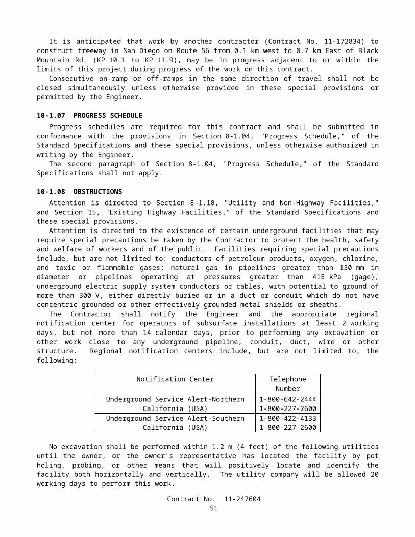
Weeds within mulched and ground cover areas and outside of plant basins shall be controlled by killing.Weeds outside of mulched areas, plant basins, ground cover, the median, and paved areas shall be controlled by mowing.
At locations where proposed planting areas are 3.6 m or more from the edges of existing plantings to remain and from shoulders, dikes, curbs, sidewalks, fences, and walls, the mowing limit shall be 2 m beyond the outer limits of the proposed planting area.
Weeds within median areas, pavement, curbs, sidewalk, and other surfaced areas shall be controlled by killing.At the option of the Contractor, plants of a larger container size than those originally specified may be used for
replacement plants during the first 125 working days of the plant establishment period. The use of plants of a larger container size than those originally specified for replacement plants shall be at the Contractor's expense.
After 125 working days of the plant establishment period have been completed, replacement of plants, except for ground cover plants, shall be No. 5 size for No. one size plants.
When ordered by the Engineer, one application of a preemergent pesticide conforming to the provisions in "Pesticides" of these special provisions, shall be applied between 40 and 50 working days prior to completion of the plant establishment period. This work will be paid for as extra work as provided in Section 4-1.03D of the Standard Specifications.
The final inspection shall be performed in conformance with the provisions in Section 5-1.13, "Final Inspection," of the Standard Specifications and shall be completed a minimum of 20 working days before the estimated completion of the contract.
10-2.05 IRRIGATION SYSTEMSIrrigation systems shall be furnished and installed in conformance with the provisions in Section 20-5, "Irrigation
Systems," of the Standard Specifications, except materials containing asbestos fibers shall not be used.Attention is directed to the provisions in "Obstructions" of these special provisions, regarding work over or adjacent to
existing underground facilities. Excavation for proposed irrigation facilities shall not be started until the existing underground facilities have been located.
Pipe supply lines shall be pressure tested in conformance with the provisions in Section 20-5.03H, "Pressure Testing," of the Standard Specifications, except the pipe (supply line) on the discharge side of the control valve shall be tested by Method B as specified in Section 20-5.03H(2), "Method B," of the Standard Specifications.
Gate valves, 75 mm and larger in size, shall be furnished with a square lug and shall be operated by use of long shank keys. Prior to acceptance of the contract, 3 long shank keys shall be delivered to the Engineer.
Gate valves 75 mm and larger in size shall be flanged type gate valves and shall have a solid brass wedge.Pipe flanges used to connect plastic or metal pipe to gate valves shall be metal.
VALVE BOXESValve boxes shall conform to the provisions in Section 20-2.24, "Valve Boxes," of the Standard Specifications, except as
otherwise provided herein.Valve boxes shall be precast portland cement concrete, fiberglass or reinforced plastic.Covers for plastic and concrete valve boxes shall be glass fiber reinforced plastic or plastic. Covers shall be one piece
without hinges.Valve boxes shall be identified on the top surface of the covers by branding the appropriate abbreviations for the
irrigation facilities contained in the valve boxes as shown on the plans. Valve boxes that contain remote control valves shall be identified by the appropriate letters and numbers (controller and station numbers). The letters and numbers shall be 50 mm in height.
ELECTRIC AUTOMATIC IRRIGATION COMPONENTS
Irrigation ControllersThe Remote Irrigation Control System (RICS) controllers shall be Rain Bird Maxicom controllers. The cluster control
unit shall communicate with the central computer by telephone line and shall communicate with the satellite by local radio.Arrangements have been made to insure that any successful bidder can obtain the specified equipment listed below from
United Green Tech, 23372 South Pointe Drive, Suite B, Laguna Hills, California 92653, telephone (949) 837-4737.The quoted prices and equipment are as follows:
Contract No. 11-24760452
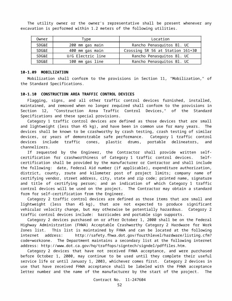
EQUIPMENT DESCRIPTION QUOTED PRICE SALES TAX EXTENDED PRICE
QUANTITYAT THIS PRICE
C28Cluster Control Unit in Assembly, Mini Clik II Rain Shut Off Assembly, Radio, Modem and LoPro Antenna Assy., Line Primary Protection
$9,336 $700 $10,036 1
RB2-32ESP 32 Station Satellite in Assembly, Radio, Modem and Whip Antenna Assy., Master Valve Relays, TRC Connector and Cable Kit, TRC Quick Connect Antenna Connector
$3,741 $281 $4,022 1
RB2-12ESP 12 Station Satellite in Assembly, Cluster Adapter Module, Master Valve Relays
$1,799 $135 $1,934 1
TRC-XRECHand Held Remote Control, TRC Transmitter and Receiver Kit, Francis Antenna Kits- Top Mount
$2,045 $158 $2,203 1
SB-36SS36" wide double door front entry enclosure
$1,310 $98 $1,408 1
Prices are guaranteed by United Green Tech for one year from the date of the quote, July 24, 2001.The contract unit price paid for equipment listed above shall include full compensation for furnishing all labor, materials,
tools, equipment, and incidentals, and for doing all the work involved in furnishing and installing the system, complete in place, as shown on the plans, as specified in the Standard Specifications and these special provisions, and as directed by the Engineer.
Attention is directed to the provisions in Section 10-3, "Electrical Systems," of these special provisions, regarding electrical power for irrigation controllers and irrigation controller enclosure cabinets.
Electric Remote Control ValvesElectric remote control valves shall conform to the provisions in Section 20-2.23, "Control Valves," of the Standard
Specifications and the following:
A. Valves shall be glass filled nylon, brass or bronze construction.B. Valves shall be angle pattern (bottom inlet) or straight pattern (side inlet) as shown on the plans.C. Valves shall be equipped with a self-flushing feature manufactured to be used with reclaimed water. Valves shall
not have external tubing.
Pull BoxesPull box installations shall conform to the provisions in Section 20-5.027I, "Conductors, Electrical Conduits and Pull
Boxes," of the Standard Specifications.
Contract No. 11-24760453
ConductorsLow voltage, as used in this section "Conductors," shall mean 36 V or less.Low voltage control and neutral conductors in pull boxes and valve boxes, at irrigation controller terminals, and at
splices shall be marked with adhesive cloth wrap-around markers.Markers for the control conductors shall be identified with the appropriate number or letter designations of irrigation
controllers and station numbers. Markers for neutral conductors shall be identified with the appropriate number or letter designations of the irrigation controllers.
New control and neutral conductors that are to replace existing control and neutral conductors shall be the same size and color as the existing control and neutral conductors being connected to.
The color of low voltage neutral and control conductor insulation, except for the striped portions, shall be homogeneous throughout the entire thickness of the insulation.
Insulation for conductors may be UL listed polyethylene conforming to UL44 test standards with a minimum insulation thickness of 1.05 mm for wire sizes 10AWG and smaller.
At the option of the Contractor, other types of splice sealing materials and methods may be used provided other materials and methods have been approved in writing by the Engineer prior to installation of the connectors.
Flow Sensor CableFlow sensor cable shall be UL listed as Type TC and meet the requirements of ICEA/NEMA, 600-V control cable,
90°C, and the following:
A. The cable shall consist of two No. 16, minimum, stranded copper conductors. Each conductor shall be insulated with 0.48-mm, minimum nominal thickness, color coded, polypropylene or polyethylene material. Color coding shall distinguish each conductor.
B. The shield shall be either tinned copper braid or aluminized polyester film with a nominal 20 percent overlap. Where the film is used, a No. 18 or larger, stranded, tinned, copper drain wire shall be placed between the insulated conductors and the shield and in contact with the conductive surface of the shield.
C. The jacket shall be black polyvinyl chloride with minimum ratings of 600 V and 90°C and a minimum nominal thickness of 1.25 mm. The cable jacket shall be marked with the manufacturer's name or trademark, insulation type designation, number of conductors and conductor size, and voltage and temperature ratings.
D. The finished outside diameter of the cable shall not exceed 8.9 mm.E. The capacitance, as measured between any conductor and the other conductors and the shield, shall not exceed 88 pf
per meter at 1000 Hz.F. The cable run between remote control valve (master) with flow meter and the irrigation controller shall be
continuous without splices.
REMOTE CONTROL VALVE (MASTER) WITH FLOW METERRemote control valve (master) with flow meter shall be installed in accordance with the details shown on the plans and
the requirements of these special provisions.The remote control valve (master) with flow meter shall consist of a remote control valve with flow meter, flow sensor
cable, and all appurtenances required to complete the installation as shown on the plans.The master remote control valve with flow meter shall be a globe type valve, consisting of diaphragm actuated hydraulic
control valve with 0.3 amp, 3-way solenoid control and built-in impeller type flow meter and brass pressure regulating pilot. Remote control valves (master) shall normally be closed.
The valves shall conform to the following:
A. Valves shall be pressure rated to 1206 kpa and shall be equipped with 8-volt, cast iron, flange type end connections which conform to ANSI Standard: B16.1, Class 125.
B. Magnetically driven vertical turbine impeller flow meters shall be accurate to plus or minus 2 percent of the actual flow.
C. Flow meters shall be equipped with an electric pulse transmitter for remote monitoring, factory preset to provide a pulse signal every 3.8 liters. Flow meter 50 mm in size shall have a flow range between 45 and 567 liters per minute.
D. Valves shall operate on the 24-volt AC voltage supplied from the irrigation controller or controllers.E. Main valve bodies and covers shall be of cast iron construction with internal and external epoxy coatings.F. Valve shall be equipped with brass fitting and copper tubing.G. Both magnetic drive control head and meter register shall be vacuum sealed.
Contract No. 11-24760454
Flow sensor cable and two low voltage conductors shall be installed in conduit between each master remote control valve with flow meter and irrigation controller as shown on the plans. Flow sensor cable shall conform to the provisions in "Flow Sensor cable," elsewhere in these special provisions.
The contract unit price paid for 50 mm remote control valve (master) with flow meter shall include full compensation for furnishing all labor, materials, tools, equipment, and incidentals, and for doing all the work involved in remote control valve (master) with flow meter, complete in place, except for enclosure and concrete pad, as shown on the plans, as specified in the Standard Specifications and these special provisions, and as directed by the Engineer.
IRRIGATION SYSTEMS FUNCTIONAL TESTFunctional tests for the remote irrigation controller system (RICS) and associated automatic irrigation systems shall
conform to the provisions in Section 20-5.027J, "Testing," of the Standard Specifications and these special provisions.Two functional tests shall be performed, one without and one with connection to the remote irrigation controller system
base station. Both tests shall consist of demonstrating to the Engineer, through one complete cycle of the irrigation controllers in the automatic mode, that the associated automatic components of the irrigation systems operate properly.
The Contractor shall notify the Engineer not less than 2 weeks prior to starting the functional tests for the remote irrigation control system.
The existing remote irrigation controller system central computer is located at the District 11 Water Manager's Office at 4120 Taylor Street, San Diego, California 92110, (619) 688-3332.
Associated automatic components for both tests shall include, but not limited to, new and existing remote control valve actuator systems, irrigation controllers, remote control valves, conductors, flow sensors, and rain sensors. Associated automatic components for the second test shall include, but not be limited to, new and existing irrigation software programs, phone systems, hand held remote controls, local two way radio communication between CCU and satellite units, and flow alarms for high mainline and remote control valves flows.
The first test shall be performed prior to planting the plants and shall consist of testing the irrigation controllers and associated automatic irrigation systems without connection to the remote irrigation controller system base station. Upon completion of a satisfactory functional test, and correction of the deficiencies, the plants to be planted in the areas watered by the irrigation system may be planted, provided the planting areas have been prepared as specified in these special provisions.
The second test shall be performed prior to the start of plant establishment and shall consist of testing the irrigation controllers (satellite) and associated automatic irrigation systems with connection to the remote irrigation controller system central computer. As part of the second test, a remote irrigation controller system watering schedule and liters per minute data base for each valve shall be submitted in written form, for each irrigation controller (satellite unit) to the Engineer. The Engineer will enter the watering schedule into the irrigation software program, and a computer printout will be made available to the Contractor for verification. If the Engineer determines the submitted watering schedule is unacceptable, a revised watering schedule shall be submitted to the Engineer for approval within 5 working days. Also as part of the second test, the Contractor shall demonstrate to the Engineer that the remote irrigation controller system central computer detects and reports the high mainline and remote control valves flow alarms. Upon completion of a satisfactory test, including correction of deficiencies, the plant establishment period may begin, provided planting work as specified in these special provisions has been completed except for plant establishment work.
If existing and new automatic components of the irrigation systems, including remote irrigation controller system central computer components, fail a functional test, the components shall be repaired. Repairs shall be at the Contractor's expense, except for repairs to an existing central computer. Testing shall be repeated until satisfactory operation is obtained.
Repair or replacement of existing irrigation facilities due to unsatisfactory performance shall conform to the provisions in Section 20-5.025, "Maintain Existing Water Supply," of the Standard Specifications and "Existing Highway Irrigation Facilities" of these special provisions.
IRRIGATION CROSSOVERS (OPEN TRENCH)Irrigation crossovers to be installed under existing surfacing shall include conduits, water line crossovers, sprinkler
control crossovers, and appurtenances and shall be installed in conformance with the details shown on the plans and these special provisions.
Conduits shall be installed in open trenches and shall conform to the provisions in Section 20-5.03B, "Conduit for Irrigation Crossovers," of the Standard Specifications.
Conduits shall be corrugated high density polyethylene (CHDPE) pipe.Water line crossovers shall conform to the provisions in Section 20-5.03C, "Water Line Crossovers," of the Standard
Specifications.Sprinkler control crossovers shall conform to the provisions in Section 20-5.027D, "Sprinkler Control Crossovers," of
the Standard Specifications.Pull boxes shall be installed in conformance with the details shown on the plans and shall conform to the provisions in
Section 20-5.027I, "Conductors, Electrical Conduit and Pull Boxes," of the Standard Specifications.Contract No. 11-247604
55

Conduits to be installed under existing pavement shall be installed in a trench approximately 300 mm wider than the outside diameter of the conduit to be installed. The top of the installed conduit shall be a minimum of 600 mm below finished grade.
Where no joint exists in a monolithic concrete sidewalk, the concrete sidewalk shall be cut on a straight neat line at the location designated by the Engineer.
Portland cement concrete curbs, concrete drainage gutters and asphalt concrete dikes shall not be cut or removed for installation of conduits.
The outline of areas of surfacing to be removed shall be cut with an abrasive type saw or a rock cutting excavator specifically designed for this purpose. The minimum depth of cuts in asphalt concrete and portland cement concrete shall be 50 mm. Cuts shall be neat and true with no shatter outside the removal area. Removed asphalt concrete, portland cement concrete and surplus excavated material shall be disposed of outside the highway right of way in conformance with the provisions in Section 7-1.13, "Disposal of Material Outside the Highway Right of Way," of the Standard Specifications.
Backfill for trenches shall be structure backfill conforming to the provisions in Section 19-3.06, "Structure Backfill," of the Standard Specifications.
The compacted thicknesses of the replacement underlying material, asphalt concrete and portland cement concrete shall be not less than the thickness of the respective material removed as specified above. The finished surface of the asphalt concrete and portland cement concrete shall be flush with the adjacent surface. Where asphalt concrete surfacing or portland cement concrete is placed adjacent to curbs, the finished surface of the asphalt concrete surfacing and portland cement concrete shall be flush with the top of the adjacent curb.
Portland cement concrete for replacing removed concrete facilities, as specified above, shall be minor concrete conforming to the provisions in Section 90-10, "Minor Concrete," of the Standard Specifications, except that the concrete shall contain not less than 350 kilograms of cement per cubic meter. Placing and finishing portland cement concrete for removed concrete facilities shall be performed by methods which will produce a concrete surface of uniform smoothness, color and texture equal to or better than the adjacent concrete surface.
Full compensation for water line crossover appurtenances, cutting, removing and disposing of existing concrete facilities; excavation and backfill; replacing existing portland cement concrete facilities; and checking and pressure testing supply line pipe in conduit shall be considered as included in the contract price paid per meter for the size and type of conduit involved and no separate payment will be made therefor.
PIPE
Steel PipeGalvanized steel pipe supply lines shall be installed as shown on the plans.
Plastic PipePlastic pipe supply lines shall be polyvinyl chloride (PVC) 1120 or 1220 pressure rated pipe with the minimum pressure
rating (PR) shown on the plans.Plastic pipe supply lines and fittings that are 75 mm or larger in diameter on the supply side of control valves shall be the
rubber ring gasket type, except when pressure rating (PR) 315 plastic pipe supply line is required.Plastic pipe supply lines less than 75 mm in diameter shall have solvent cemented type joints. Primers shall be used on
the solvent cemented type joints.Plastic pipe supply lines (main) shall have a minimum cover of 0.45 m.Fittings for plastic pipe supply lines with a pressure rating (PR) of 315 shall be Schedule 80.Plastic pipe (supply line) 40 mm in size will be measured and paid for as 32 mm plastic pipe (supply line).
FERTILIZER COUPLINGFertilizer coupling shall be constructed in accordance with the details shown on the plans and the requirements of these
special provisions.The fertilizer coupling shall consist of an aluminum cam and groove coupling with dust cap, ball valve and all piping
required to complete the assembly in place as shown on the plans.The quantity of fertilizer couplings will be measured by the unit as determined from actual count in placeThe contract unit price paid for fertilizer coupling shall include full compensation for furnishing all labor, materials,
tools, equipment, and incidentals, and for doing all the work involved in fertilizer coupling, complete in place, including valve box, as shown on the plans, as specified in the Standard Specifications and these special provisions, and as directed by the Engineer.
Contract No. 11-24760456
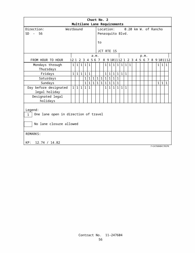
SPRINKLERSSprinklers shall conform to the type, pattern, material, and operating characteristics listed in the "Sprinkler Schedule"
shown on the plans.
FINAL IRRIGATION SYSTEM CHECKA final check of existing and new irrigation facilities shall be performed not more than 20 working days prior to
acceptance of the contract.The length of watering cycles using potable water measured by water meters for the final check of irrigation facilities
will be determined by the Engineer.Remote control valves connected to existing and new irrigation controllers shall be checked for automatic performance
when the controllers are in automatic mode.Unsatisfactory performance of irrigation facilities installed or modified by the Contractor shall be repaired and rechecked
at the Contractor's expense until satisfactory performance is obtained, as determined by the Engineer.Repair or replacement of existing irrigation facilities due to unsatisfactory performance shall conform to the provisions
in "Existing Highway Irrigation Facilities" of these special provisions.Nothing in this section "Final Irrigation System Check" shall relieve the Contractor of full responsibility for making
good or repairing defective work or materials found before the formal written acceptance of the entire contract by the Director.
Full compensation for checking the irrigation systems prior to the acceptance of the contract shall be considered as included in the contract lump sum price paid for plant establishment work and no additional compensation will be allowed therefor.
SECTION 10-3. ELECTRICAL SYSTEMS
10-3.01 DESCRIPTIONIrrigation controller enclosure cabinet and electric service (irrigation) shall conform to the provisions in Section 86,
"Signals, Lighting and Electrical Systems," of the Standard Specifications and these special provisions.
10-3.02 COST BREAK-DOWNCost break-downs shall conform to the provisions in Section 86-1.03, "Cost Break-Down," of the Standard
Specifications and these special provisions.The Engineer shall be furnished a cost break-down for each contract lump sum item of work described in this
Section 10-3.The cost break-down shall be submitted to the Engineer for approval within 15 days after the contract has been
approved. The cost break-down shall be approved, in writing, by the Engineer before any partial payment for the items of electrical work will be made.
10-3.03 CONDUITConduit to be installed underground shall be Type 3 unless otherwise specified.The conduit in a foundation and between a foundation and the nearest pull box shall be Type 3.Conduit sizes shown on the plans and specified in the Standard Specifications and these special provisions are referenced
to metallic type conduit. When rigid non-metallic conduit is required or allowed, the nominal equivalent industry size shall be used as shown in the following table:
Size Designation for Metallic Type Conduit Equivalent Size for Rigid Non-metallic Conduit21 2027 2541 4053 5063 6578 75103 100
Contract No. 11-24760457
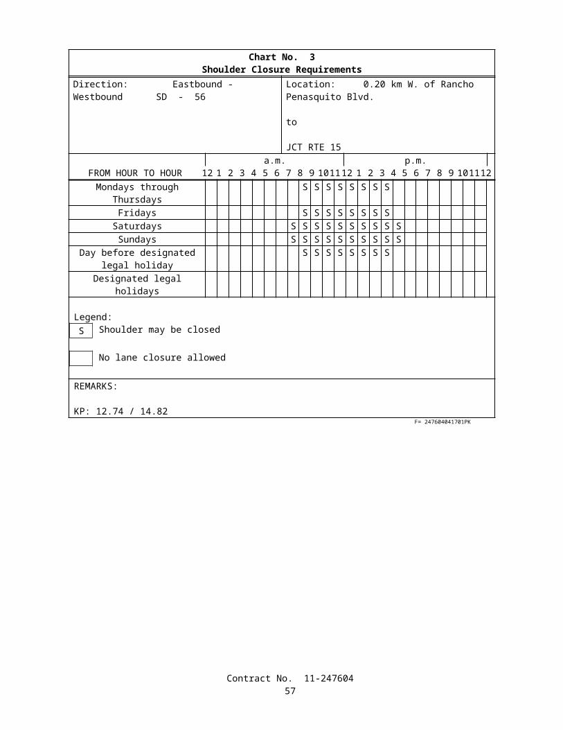
When Type 3 conduit is placed in a trench (not in pavement or under portland cement concrete sidewalk), after the bedding material is placed and the conduit is installed, the trench shall be backfilled with commercial quality concrete, containing not less than 250 kg of portland cement per cubic meter, to not less than 100 mm above the conduit before additional backfill material is placed.
After conductors have been installed, the ends of conduits terminating in pull boxes, service equipment enclosures, and controller cabinets shall be sealed with an approved type of sealing compound.
10-3.04 PULL BOXESGrout shall not be placed in the bottom of pull boxes.Where the sump of an existing pull box is disturbed by the Contractor's operation, the sump shall be reconstructed as
shown on Standard Plan ES-8.
10-3.05 CONDUCTORS AND WIRINGSplices of conductors shall be insulated with heat-shrink tubing of the appropriate size after thoroughly painting the
spliced conductors with electrical insulating coating.Heat-shrink tubing shall be heated as recommended by the manufacturer.The minimum insulation thickness, at any point, for Type USE, RHH or RHW wire shall be 1.0 mm for conductor sizes
No. 14 to No. 10, inclusive, and 1.3 mm for No. 8 to No. 2, inclusive. The minimum insulation thickness, at any point, for Type THW and TW wires shall be 0.69 mm for conductor sizes No. 14 to No. 10, inclusive, 1.02 mm for No. 8, and 1.37 mm for No. 6 to No. 2, inclusive.
10-3.06 SERVICECircuit breakers shall be the cable-in/cable-out type, mounted on non-energized clips. All circuit breakers shall be
mounted vertically with the up position of the handle being the "ON" position.
ELECTRIC SERVICE (IRRIGATION)Electric service (irrigation) shall be from the service points to the irrigation controllers (IC) and to the spaces provided in
the irrigation controller enclosure cabinets (CEC) for irrigation controllers as shown on the plans.
The inscription on nameplates shall be the identifying letter designation used on the plans and in these special provisions, or shall be as directed by the Engineer.
10-3.07 IRRIGATION CONTROLLER ENCLOSURE CABINETIrrigation controller enclosure cabinets (CEC) shall be constructed and the equipment within the cabinets shall be
installed in conformance with the details shown on the plans, the provisions in the Standard Specifications, and these special provisions.
Irrigation controller enclosure cabinets shall be fabricated in conformance with the provisions in Section 86-3.04A, "Cabinet Construction," of the Standard Specifications.
Irrigation controller enclosure cabinets shall be fabricated of stainless steel.Door locks for the irrigation controller enclosure cabinets shall be a removable-core mortise cam cylinder door lock that
receives the State's lock core. The State's lock core is a "Best" construction core. Keys shall be removable from the locks in the locked position only. Door locks shall be installed in conformance with the manufacturer's written instructions and recommendations. Two keys for each door lock shall be delivered to the Engineer.
Irrigation controller enclosure cabinet door handles shall have provisions for padlocking in the latched position. Padlocks will be State-furnished as provided under "Materials" of these special provisions.
Inside of the doors shall have provisions for storage of the irrigation plans.Duplex convenience receptacles shall have ground-fault circuit interruption as defined by the Code. Circuit interruption
shall occur on 6 mA of ground-fault current and shall not occur on less than 4 mA. Receptacles shall be installed in a weatherproof housing with rainproof lift covers.
Solid-state automatic shut-off rain sensor units shall be installed for the irrigation controller enclosure cabinets. Rain sensor units shall automatically interrupt the master remote control valves when approximately 3 mm of rain has fallen. The irrigation system shall automatically be enabled again when the accumulated rainfall evaporates from the rain sensor unit collection cup. Rain sensor units shall be rated 24 V (ac) to 30 V (ac). Static charge protection shall be included to protect against lightning damage.
Equipment, except for field wiring, shall be installed in the cabinet in a shop by the equipment manufacturer's representative or distributor prior to field installation.
Contract No. 11-24760458
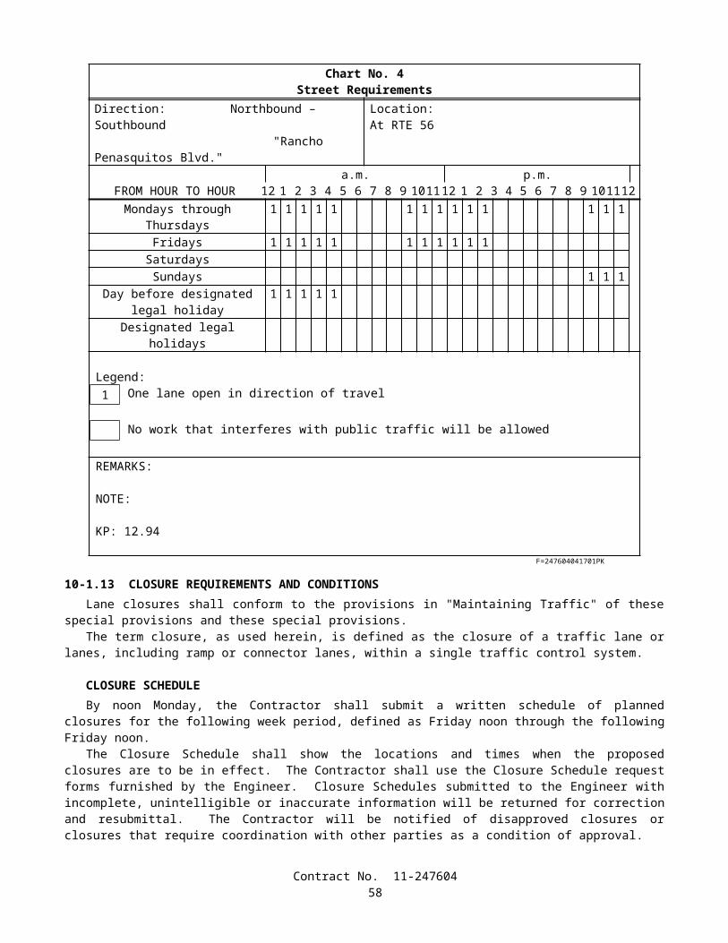
10-3.08 PAYMENTElectric service (irrigation) will be paid for on a lump sum basis.The contract lump sum price paid for electric service (irrigation) shall include full compensation for furnishing all labor,
materials, tools, equipment, and incidentals, and for doing all the work involved in installing electric service (irrigation) for irrigation controllers, complete in place, including conductors, conduit and pull boxes to the pull box adjacent to irrigation controller enclosure cabinets and irrigation controllers, as shown on the plans, as specified in these special provisions, and as directed by the Engineer.
Irrigation controller enclosure cabinets will be measured by the unit as determined from actual count in place.The contract unit price paid for irrigation controller enclosure cabinet shall include full compensation for furnishing all
labor, materials, tools, equipment (including rain sensor units), and incidentals, and for doing all the work involved in fabricating and installing irrigation controller enclosure cabinets, complete in place, including constructing foundations, pads and conduits to pull box adjacent to cabinets, and installing equipment within the cabinets, except controllers, as shown on the plans, as specified in the Standard Specifications and these special provisions, and as directed by the Engineer.
SECTION 11. MODIFIED STANDARD SPECIFICATION SECTIONS
SECTION 11-1. (BLANK)
SECTION 11-2. PORTLAND CEMENT CONCRETE
11-2.01 GENERALPortland cement concrete shall conform to the provisions in this Section 11-2, "Portland Cement Concrete," and the
section entitled "Portland Cement Concrete" in Section 8, "Materials," of these special provisions. Section 90, "Portland Cement Concrete," of the Standard Specifications is deleted. Section 90, "Portland Cement Concrete," of the Standard Specifications is amended to read as follows.
SECTION 90: PORTLAND CEMENT CONCRETE90-1 GENERAL
90-1.01 DESCRIPTION Portland cement concrete shall be composed of cementitious material, fine aggregate, coarse aggregate, admixtures
if used, and water, proportioned and mixed as specified in these specifications. The Contractor shall determine the mix proportions for all concrete except pavement concrete. The Engineer will
determine the mix proportions for pavement concrete. Concrete for which the mix proportions are determined either by the Contractor or the Engineer shall conform to the requirements of this Section 90.
Unless otherwise specified, cementitious material shall be a combination of cement and mineral admixture. Cementitious material shall be either:
1. "Type IP (MS) Modified" cement; or 2. A combination of "Type II Modified" portland cement and mineral admixture; or3. A combination of Type V portland cement and mineral admixture.
Type III portland cement shall be used only as allowed in the special provisions or with the approval of the Engineer.
Class 1 concrete shall contain not less than 400 kg of cementitious material per cubic meter. Class 2 concrete shall contain not less than 350 kg of cementitious material per cubic meter. Class 3 concrete shall contain not less than 300 kg of cementitious material per cubic meter. Class 4 concrete shall contain not less than 250 kg of cementitious material per cubic meter. Minor concrete shall contain not less than 325 kg of cementitious material per cubic meter unless otherwise
specified in these specifications or the special provisions. Unless otherwise designated on the plans or specified in these specifications or the special provisions, the amount of
cementitious material used per cubic meter of concrete in structures or portions of structures shall conform to the following:
Contract No. 11-24760459
Use Cementitious Material Content(kg/m3)
Concrete designated by compressive strength:Deck slabs and slab spans of bridgesRoof sections of exposed top box culvertsOther portions of structures
400 min., 475 max.400 min., 475 max.350 min., 475 max.
Concrete not designated by compressive strength:Deck slabs and slab spans of bridgesRoof sections of exposed top box culvertsPrestressed membersSeal coursesOther portions of structures
400 min.400 min.400 min.400 min.350 min.
Concrete for precast members 350 min., 550 max.
Whenever the 28-day compressive strength shown on the plans is greater than 25 MPa, the concrete shall be designated by compressive strength. If the plans show a 28-day compressive strength that is 28 MPa or greater, an additional 14 days will be allowed to obtain the specified strength. The 28-day compressive strengths shown on the plans that are 25 MPa or less are shown for design information only and are not a requirement for acceptance of the concrete.
Concrete designated by compressive strength shall be proportioned such that the concrete will attain the strength shown on the plans or specified in the special provisions.
Before using concrete for which the mix proportions have been determined by the Contractor, or in advance of revising those mix proportions, the Contractor shall submit in writing to the Engineer a copy of the mix design.
Compliance with cementitious material content requirements will be verified in conformance with procedures described in California Test 518 for cement content. For testing purposes, mineral admixture shall be considered to be cement. Batch proportions shall be adjusted as necessary to produce concrete having the specified cementitious material content.
If any concrete has a cementitious material, portland cement, or mineral admixture content that is less than the minimum required, the concrete shall be removed. However, if the Engineer determines that the concrete is structurally adequate, the concrete may remain in place and the Contractor shall pay to the State $0.55 for each kilogram of cementitious material, portland cement, or mineral admixture that is less than the minimum required. The Department may deduct the amount from any moneys due, or that may become due, the Contractor under the contract. The deductions will not be made unless the difference between the contents required and those actually provided exceeds the batching tolerances permitted by Section 90-5, "Proportioning." No deductions will be made based on the results of California Test 518.
The requirements of the preceding paragraph shall not apply to minor concrete or commercial quality concrete.
90-2 MATERIALS
90-2.01 CEMENT Unless otherwise specified, cement shall be either "Type IP (MS) Modified" cement, "Type II Modified" portland
cement or Type V portland cement. "Type IP (MS) Modified" cement shall conform to the requirements for Type IP (MS) cement in ASTM
Designation: C 595, and shall be comprised of an intimate and uniform blend of Type II cement and not more than 35 percent by mass of mineral admixture. The type and minimum amount of mineral admixture used in the manufacture of "Type IP (MS) Modified" cement shall be in conformance with the provisions in Section 90-4.08, "Required Use of Mineral Admixtures."
"Type II Modified" portland cement shall conform to the requirements for Type II portland cement in ASTM Designation: C 150.
In addition, "Type IP (MS) Modified" cement and "Type II Modified" portland cement shall conform to the following requirements:
A. The cement shall not contain more than 0.60 percent by mass of alkalies, calculated as the percentage of Na2O plus 0.658 times the percentage of K2O, when determined by either direct intensity flame photometry or by the atomic absorption method. The instrument and procedure used shall be qualified as to precision and accuracy in conformance with the requirements in ASTM Designation: C 114;
B. The autoclave expansion shall not exceed 0.50 percent; and
Contract No. 11-24760460
C. Mortar, containing the cement to be used and Ottawa sand, when tested in conformance with California Test 527, shall not expand in water more than 0.010 percent and shall not contract in air more than 0.048 percent, except that when cement is to be used for precast prestressed concrete piling, precast prestressed concrete members, or steam cured concrete products, the mortar shall not contract in air more than 0.053 percent.
Type III and Type V portland cements shall conform to the requirements in ASTM Designation: C 150 and the additional requirements listed above for "Type II Modified" portland cement, except that when tested in conformance with California Test 527, mortar containing Type III portland cement shall not contract in air more than 0.075 percent.
Cement used in the manufacture of cast-in-place concrete for exposed surfaces of like elements of a structure shall be from the same cement mill.
Cement shall be protected from exposure to moisture until used. Sacked cement shall be piled to permit access for tally, inspection, and identification of each shipment.
Adequate facilities shall be provided to assure that cement meeting the provisions specified in this Section 90 -2.01 shall be kept separate from other cement in order to prevent any but the specified cement from entering the work. Safe and suitable facilities for sampling cement shall be provided at the weigh hopper or in the feed line immediately in advance of the hopper, in conformance with California Test 125.
If cement is used prior to sampling and testing as provided in Section 6-1.07, "Certificates of Compliance," and the cement is delivered directly to the site of the work, the Certificate of Compliance shall be signed by the cement manufacturer or supplier of the cement. If the cement is used in ready-mixed concrete or in precast concrete products purchased as such by the Contractor, the Certificate of Compliance shall be signed by the manufacturer of the concrete or product.
Cement furnished without a Certificate of Compliance shall not be used in the work until the Engineer has had sufficient time to make appropriate tests and has approved the cement for use.
90-2.02 AGGREGATES Aggregates shall be free from deleterious coatings, clay balls, roots, bark, sticks, rags, and other extraneous material. Natural aggregates shall be thoroughly and uniformly washed before use. The Contractor, at the Contractor's expense, shall provide safe and suitable facilities, including necessary splitting
devices for obtaining samples of aggregates, in conformance with California Test 125. Aggregates shall be of such character that it will be possible to produce workable concrete within the limits of water
content provided in Section 90-6.06, "Amount of Water and Penetration." Aggregates shall have not more than 10 percent loss when tested for soundness in conformance with the
requirements in California Test 214. The soundness requirement for fine aggregate will be waived, provided that the durability index, Df, of the fine aggregate is 60, or greater, when tested for durability in conformance with California Test 229.
If the results of any one or more of the Cleanness Value, Sand Equivalent, or aggregate grading tests do not meet the requirements specified for "Operating Range" but all meet the "Contract Compliance" requirements, the placement of concrete shall be suspended at the completion of the current pour until tests or other information indicate that the next material to be used in the work will comply with the requirements specified for "Operating Range."
If the results of either or both the Cleanness Value and coarse aggregate grading tests do not meet the requirements specified for "Contract Compliance," the concrete that is represented by the tests shall be removed. However, if the Engineer determines that the concrete is structurally adequate, the concrete may remain in place, and the Contractor shall pay to the State $4.60 per cubic meter for paving concrete and $7.20 per cubic meter for all other concrete for the concrete represented by these tests and left in place. The Department may deduct the amount from any moneys due, or that may become due, the Contractor under the contract.
If the results of either or both the Sand Equivalent and fine aggregate grading tests do not meet the requirements specified for "Contract Compliance," the concrete which is represented by the tests shall be removed. However, if the Engineer determines that the concrete is structurally adequate, the concrete may remain in place, and the Contractor shall pay to the State $4.60 per cubic meter for paving concrete and $7.20 per cubic meter for all other concrete for the concrete represented by these tests and left in place. The Department may deduct the amount from any moneys due, or that may become due, the Contractor under the contract.
The 2 preceding paragraphs apply individually to the "Contract Compliance" requirements for coarse aggregate and fine aggregate. When both coarse aggregate and fine aggregate do not conform to the "Contract Compliance" requirements, both paragraphs shall apply. The payments specified in those paragraphs shall be in addition to any payments made in conformance with the provisions in Section 90-1.01, "Description."
No single Cleanness Value, Sand Equivalent or aggregate grading test shall represent more than 250 m3 of concrete or one day's pour, whichever is smaller.
Aggregates specified for freeze-thaw resistance shall pass the freezing and thawing test, California Test 528.
Contract No. 11-24760461
The Contractor shall notify the Engineer of the proposed source of freeze-thaw resistant concrete aggregates at least 4 months before intended use. Should the Contractor later propose a different source of concrete aggregates, the Contractor shall again notify the Engineer at least 4 months before intended use. Blending of fine or coarse aggregates from untested sources with acceptable aggregates will not be permitted. Provisions for the time of submission of samples as provided in Section 40-1.015, "Cement Content," are superseded by the foregoing.
Concurrently with notification of proposed sources of freeze-thaw resistant concrete aggregates, the Contractor shall furnish samples in the quantity ordered by the Engineer. The samples shall be secured under the direct supervision of the Engineer. Samples from existing stockpiles of processed aggregate shall be taken from washed materials and shall be visibly damp. Samples from materials in place in a material source shall be taken at depths from the existing surface that will ensure the presence of the full quantity of ground water. Excavations for the purpose of securing samples shall be made to the full depth of intended source operations. Samples shall be protected against loss of contained water until they are delivered to the Engineer.
The Engineer will waive the above freeze-thaw test and the 4-month advance notice, required in this Section, provided aggregates are to be obtained from sources that have previously passed this test and test results are currently applicable.
No extension of contract time will be allowed for the time required to perform the freezing and thawing test. When the source of an aggregate is changed, except for pavement concrete, the Contractor shall adjust the mix
proportions and submit in writing to the Engineer a copy of the mix design before using the aggregates. When the source of an aggregate is changed for pavement concrete, the Engineer shall be allowed sufficient time to adjust the mix, and the aggregates shall not be used until necessary adjustments are made.
90-2.02A Coarse Aggregate Coarse aggregate shall consist of gravel, crushed gravel, crushed rock, crushed air-cooled iron blast furnace slag or
combinations thereof. Crushed air-cooled blast furnace slag shall not be used in reinforced or prestressed concrete. Coarse aggregate shall conform to the following quality requirements:
TestsCalifornia
Test RequirementsLoss in Los Angeles Rattler (after 500 revolutions)
211 45% max.
Cleanness ValueOperating Range 227 75 min.Contract Compliance 227 71 min.
In lieu of the above Cleanness Value requirements, a Cleanness Value "Operating Range" limit of 71, minimum, and a Cleanness Value "Contract Compliance" limit of 68, minimum, will be used to determine the acceptability of the coarse aggregate if the Contractor furnishes a Certificate of Compliance, as provided in Section 6-1.07, "Certificates of Compliance," certifying that:
1. coarse aggregate sampled at the completion of processing at the aggregate production plant had a Cleanness Value of not less than 82 when tested by California Test 227; and
2. prequalification tests performed in conformance with the requirements in California Test 549 indicated that the aggregate would develop a relative strength of not less than 95 percent and would have a relative shrinkage not greater than 105 percent, based on concrete.
90-2.02B Fine Aggregate Fine aggregate shall consist of natural sand, manufactured sand produced from larger aggregate or a combination
thereof. Manufactured sand shall be well graded. Fine aggregate shall conform to the following quality requirements:
Contract No. 11-24760462
TestCalifornia
Test RequirementsOrganic Impurities 213 Satisfactorya
Mortar Strengths Relative to Ottawa Sand 515 95%, min.Sand Equivalent:
Operating Range 217 75, min.Contract Compliance 217 71, min.
a Fine aggregate developing a color darker than the reference standard color solution may be accepted if it is determined by the Engineer, from mortar strength tests, that a darker color is acceptable.
In lieu of the above Sand Equivalent requirements, a Sand Equivalent "Operating Range" limit of 71 minimum and a Sand Equivalent "Contract Compliance" limit of 68 minimum will be used to determine the acceptability of the fine aggregate if the Contractor furnishes a Certificate of Compliance, as provided in Section 6-1.07, "Certificates of Compliance," certifying that:
1. fine aggregate sampled at the completion of processing at the aggregate production plant had a Sand Equivalent value of not less than 82 when tested by California Test 217; and
2. prequalification tests performed in conformance with California Test 549 indicated that the aggregate would develop a relative strength of not less than 95 percent and would have a relative shrinkage not greater than 105 percent, based on concrete.
90-2.03 WATER In conventionally reinforced concrete work, the water for curing, for washing aggregates, and for mixing shall be
free from oil and shall not contain more than 1000 parts per million of chlorides as Cl, when tested in conformance with California Test 422, nor more than 1300 parts per million of sulfates as SO4, when tested in conformance with California Test 417. In prestressed concrete work, the water for curing, for washing aggregates, and for mixing shall be free from oil and shall not contain more than 650 parts per million of chlorides as Cl, when tested in conformance with California Test 422, nor more than 1300 parts per million of sulfates as SO4, when tested in conformance with California Test 417. In no case shall the water contain an amount of impurities that will cause either: 1) a change in the setting time of cement of more than 25 percent when tested in conformance with the requirements in ASTM Designation: C 191 or ASTM Designation: C 266 or 2) a reduction in the compressive strength of mortar at 14 days of more than 5 percent, when tested in conformance with the requirements in ASTM Designation: C 109, when compared to the results obtained with distilled water or deionized water, tested in conformance with the requirements in ASTM Designation: C 109.
In non-reinforced concrete work, the water for curing, for washing aggregates and for mixing shall be free from oil and shall not contain more than 2000 parts per million of chlorides as Cl, when tested in conformance with California Test 422, or more than 1500 parts per million of sulfates as SO4, when tested in conformance with California Test 417.
In addition to the above provisions, water for curing concrete shall not contain impurities in a sufficient amount to cause discoloration of the concrete or produce etching of the surface.
Water reclaimed from mixer wash-out operations may be used in mixing concrete. The water shall not contain coloring agents or more than 300 parts per million of alkalis (Na2O + 0.658 K2O) as determined on the filtrate. The specific gravity of the water shall not exceed 1.03 and shall not vary more than ±0.010 during a day's operations.
90-2.04 ADMIXTURE MATERIALS Admixture materials shall conform to the requirements in the following ASTM Designations:
A. Chemical Admixtures—ASTM Designation: C 494.B. Air-entraining Admixtures—ASTM Designation: C 260.C. Calcium Chloride—ASTM Designation: D 98.D. Mineral Admixtures—Coal fly ash; raw or calcined natural pozzolan as specified in ASTM Designation: C618;
silica fume conforming to the requirements in ASTM Designation: C1240, with reduction of mortar expansion of 80 percent, minimum, using the cement from the proposed mix design.
Unless otherwise specified in the special provisions, mineral admixtures shall be used in conformance with the provisions in Section 90-4.08, "Required Use of Mineral Admixtures."
Contract No. 11-24760463
90-3 AGGREGATE GRADINGS
90-3.01 GENERAL Before beginning concrete work, the Contractor shall submit in writing to the Engineer the gradation of the primary
aggregate nominal sizes that the Contractor proposes to furnish. If a primary coarse aggregate or the fine aggregate is separated into 2 or more sizes, the proposed gradation shall consist of the gradation for each individual size, and the proposed proportions of each individual size, combined mathematically to indicate one proposed gradation. The proposed gradation shall meet the grading requirements shown in the table in this section, and shall show the percentage passing each of the sieve sizes used in determining the end result.
The Engineer may waive, in writing, the gradation requirements in this Section 90-3.01 and in Sections 90-3.02, "Coarse Aggregate Grading," 90-3.03, "Fine Aggregate Grading," and 90-3.04, "Combined Aggregate Gradings," if, in the Engineer's opinion, furnishing the gradation is not necessary for the type or amount of concrete work to be constructed.
Gradations proposed by the Contractor shall be within the following percentage passing limits:
Primary Aggregate Nominal Size Sieve Size Limits of Proposed Gradation37.5-mm x 19-mm 25-mm 19 - 4125-mm x 4.75-mm 19-mm 52 - 8525-mm x 4.75-mm 9.5-mm 15 - 3812.5-mm x 4.75-mm 9.5-mm 40 - 78 9.5-mm x 2.36-mm 9.5-mm 50 - 85 Fine Aggregate 1.18-mm 55 - 75Fine Aggregate 600-µm 34 - 46Fine Aggregate 300-µm 16 - 29
Should the Contractor change the source of supply, the Contractor shall submit in writing to the Engineer the new gradations before their intended use.
90-3.02 COARSE AGGREGATE GRADING The grading requirements for coarse aggregates are shown in the following table for each size of coarse aggregate:
Percentage Passing Primary Aggregate Nominal Sizes37.5-mm x 19-mm 25-mm x 4.75-mm 12.5-mm x 4.75-mm 9.5-mm x 2.36-mm
Operating Contract Operating Contract Operating Contract Operating ContractSieve Sizes Range Compliance Range Compliance Range Compliance Range Compliance50-mm 100 100 — — — — — —37.5-mm 88-100 85-100 100 100 — — — —25-mm x ± 18 X ± 25 88-100 86-100 — — — —19-mm 0-17 0-20 X ± 15 X ± 22 100 100 — —12.5-mm — — — — 82-100 80-100 100 1009.5-mm 0-7 0-9 X ± 15 X ± 22 X ± 15 X ± 22 X ± 15 X ± 204.75-mm — — 0-16 0-18 0-15 0-18 0-25 0-282.36-mm — — 0-6 0-7 0-6 0-7 0-6 0-7
In the above table, the symbol X is the gradation that the Contractor proposes to furnish for the specific sieve size as provided in Section 90-3.01, "General."
Coarse aggregate for the 37.5-mm, maximum, combined aggregate grading as provided in Section 90-3.04, "Combined Aggregate Gradings," shall be furnished in 2 or more primary aggregate nominal sizes. Each primary aggregate nominal size may be separated into 2 sizes and stored separately, provided that the combined material conforms to the grading requirements for that particular primary aggregate nominal size.
When the 25-mm, maximum, combined aggregate grading as provided in Section 90-3.04, "Combined Aggregate Gradings," is to be used, the coarse aggregate may be separated into 2 sizes and stored separately, provided that the combined material shall conform to the grading requirements for the 25-mm x 4.75-mm primary aggregate nominal size.
Contract No. 11-24760464
90-3.03 FINE AGGREGATE GRADING Fine aggregate shall be graded within the following limits:
Percentage PassingSieve Sizes Operating Range Contract Compliance
9.5-mm 100 1004.75-mm 95-100 93-1002.36-mm 65-95 61-991.18-mm X ± 10 X ± 13600-µm X ± 9 X ± 12300-µm X ± 6 X ± 9150-µm 2-12 1-1575-µm 0-8 0-10
In the above table, the symbol X is the gradation that the Contractor proposes to furnish for the specific sieve size as provided in Section 90-3.01, "General."
In addition to the above required grading analysis, the distribution of the fine aggregate sizes shall be such that the difference between the total percentage passing the 1.18-mm sieve and the total percentage passing the 600-µm sieve shall be between 10 and 40, and the difference between the percentage passing the 600-µm and 300-µm sieves shall be between 10 and 40.
Fine aggregate may be separated into 2 or more sizes and stored separately, provided that the combined material conforms to the grading requirements specified in this Section 90-3.03.
90-3.04 COMBINED AGGREGATE GRADINGS Combined aggregate grading limits shall be used only for the design of concrete mixes. Concrete mixes shall be
designed so that aggregates are combined in proportions that shall produce a mixture within the grading limits for combined aggregates as specified herein. Within these limitations, the relative proportions shall be as ordered by the Engineer, except as otherwise provided in Section 90-1.01, "Description."
The combined aggregate grading used in portland cement concrete pavement shall be the 37.5-mm, maximum grading.
The combined aggregate grading used in concrete for structures and other concrete items, except when specified otherwise in these specifications or the special provisions, shall be either the 37.5-mm, maximum grading, or the 25-mm, maximum grading, at the option of the Contractor.
Grading Limits of Combined AggregatesPercentage Passing
Sieve Sizes 37.5-mm Max. 25-mm Max. 12.5-mm Max. 9.5-mm Max.50-mm 100 — — —37.5-mm 90-100 100 — —25-mm 50-86 90-100 — —19-mm 45-75 55-100 100 —12.5-mm — — 90-100 1009.5-mm 38-55 45-75 55-86 50 - 1004.75-mm 30-45 35-60 45-63 45 - 632.36-mm 23-38 27-45 35-49 35 - 491.18-mm 17-33 20-35 25-37 25 - 37600-µm 10-22 12-25 15-25 15 - 25300-µm 4-10 5-15 5-15 5 - 15150-µm 1-6 1-8 1-8 1 - 875-µm 0-3 0-4 0-4 0 - 4
Changes from one grading to another shall not be made during the progress of the work unless permitted by the Engineer.
Contract No. 11-24760465
90-4 ADMIXTURES90-4.01 GENERAL
Admixtures used in portland cement concrete shall conform to and be used in conformance with the provisions in this Section 90-4 and the special provisions. Admixtures shall be used when specified or ordered by the Engineer and may be used at the Contractor's option as provided herein.
Chemical admixtures and air-entraining admixtures containing chlorides as Cl in excess of one percent by mass of admixture, as determined by California Test 415, shall not be used in prestressed or reinforced concrete.
Calcium chloride shall not be used in concrete containing steel reinforcement or other embedded metals. Mineral admixture used in concrete for exposed surfaces of like elements of a structure shall be from the same
source and of the same percentage. Admixtures shall be uniform in properties throughout their use in the work. Should it be found that an admixture as
furnished is not uniform in properties, its use shall be discontinued. If more than one admixture is used, the admixtures shall be compatible with each other so that the desirable effects
of all admixtures used will be realized.
90-4.02 MATERIALS Admixture materials shall conform to the provisions in Section 90–2.04, "Admixture Materials."
90-4.03 ADMIXTURE APPROVAL No admixture brand shall be used in the work unless it is on the Department's current list of approved brands for the
type of admixture involved. Admixture brands will be considered for addition to the approved list if the manufacturer of the admixture submits
to the Transportation Laboratory a sample of the admixture accompanied by certified test results demonstrating that the admixture complies with the requirements in the appropriate ASTM Designation and these specifications. The sample shall be sufficient to permit performance of all required tests. Approval of admixture brands will be dependent upon a determination as to compliance with the requirements, based on the certified test results submitted, together with tests the Department may elect to perform.
When the Contractor proposes to use an admixture of a brand and type on the current list of approved admixture brands, the Contractor shall furnish a Certificate of Compliance from the manufacturer, as provided in Section 6 -1.07, "Certificates of Compliance," certifying that the admixture furnished is the same as that previously approved. If a previously approved admixture is not accompanied by a Certificate of Compliance, the admixture shall not be used in the work until the Engineer has had sufficient time to make the appropriate tests and has approved the admixture for use. The Engineer may take samples for testing at any time, whether or not the admixture has been accompanied by a Certificate of Compliance.
If a mineral admixture is delivered directly to the site of the work, the Certificate of Compliance shall be signed by the manufacturer or supplier of the mineral admixture. If the mineral admixture is used in ready-mix concrete or in precast concrete products purchased as such by the Contractor, the Certificate of Compliance shall be signed by the manufacturer of the concrete or product.
90-4.04 REQUIRED USE OF CHEMICAL ADMIXTURES AND CALCIUM CHLORIDE When the use of a chemical admixture or calcium chloride is specified or ordered by the Engineer, the admixture
shall be used at the dosage specified or ordered, except that if no dosage is specified or ordered, the admixture shall be used at the dosage normally recommended by the manufacturer of the admixture.
Calcium chloride shall be dispensed in liquid, flake, or pellet form. Calcium chloride dispensed in liquid form shall conform to the provisions for dispensing liquid admixtures in Section 90-4.10, "Proportioning and Dispensing Liquid Admixtures."
90-4.05 OPTIONAL USE OF CHEMICAL ADMIXTURES The Contractor will be permitted to use Type A or F, water-reducing; Type B, retarding; or Type D or G, water-
reducing and retarding admixtures as described in ASTM Designation: C 494 to conserve cementitious material or to facilitate any concrete construction application subject to the following conditions:
A. When a water-reducing admixture or a water-reducing and retarding admixture is used, the cementitious material content specified or ordered may be reduced by a maximum of 5 percent by mass, except that the resultant cementitious material content shall be not less than 300 kilograms per cubic meter; and
B. When a reduction in cementitious material content is made, the dosage of admixture used shall be the dosage used in determining approval of the admixture.
Contract No. 11-24760466
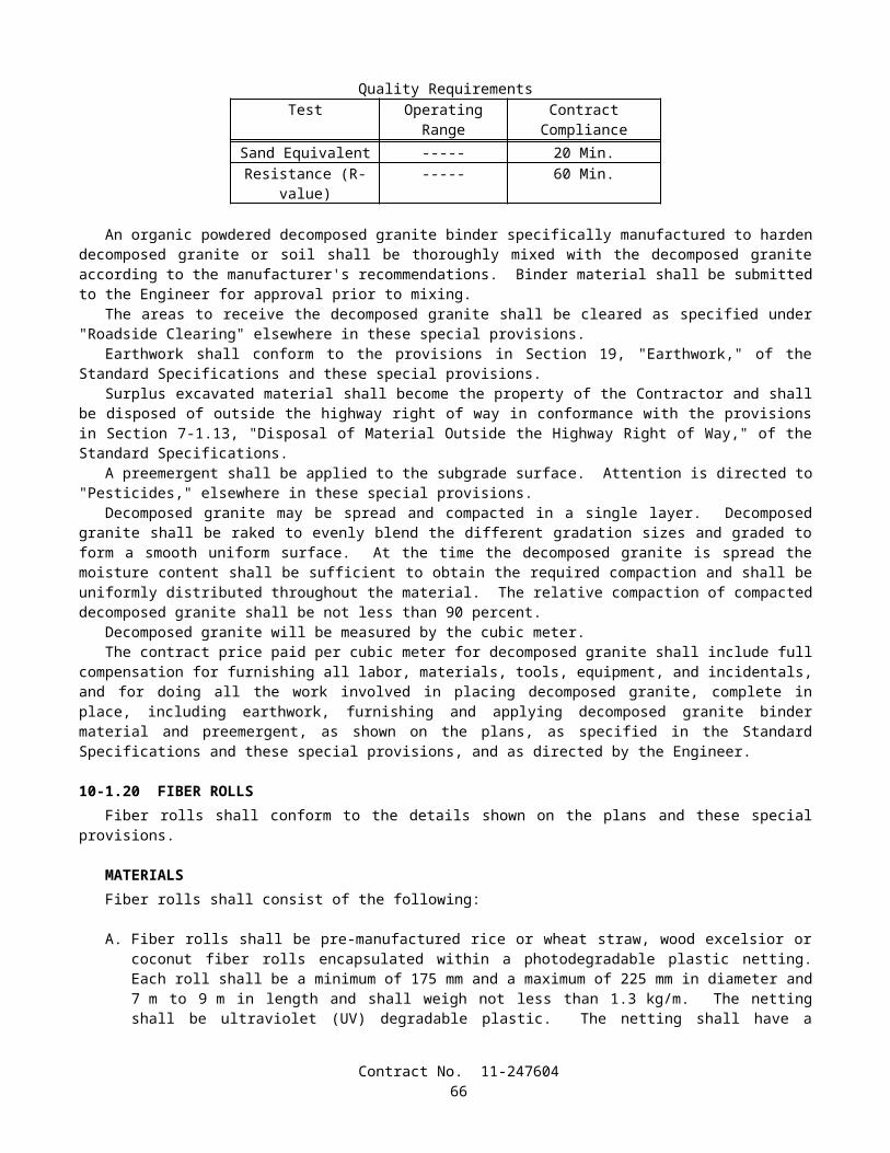
Unless otherwise specified, a Type C accelerating chemical admixture conforming to the requirements in ASTM Designation: C 494, may be used in portland cement concrete. Inclusion in the mix design submitted for approval will not be required provided that the admixture is added to counteract changing conditions that contribute to delayed setting of the portland cement concrete, and the use or change in dosage of the admixture is approved in writing by the Engineer.
90-4.06 REQUIRED USE OF AIR-ENTRAINING ADMIXTURES When air-entrainment is specified or ordered by the Engineer, the air-entraining admixture shall be used in amounts
to produce a concrete having the specified air content as determined by California Test 504.
90-4.07 OPTIONAL USE OF AIR-ENTRAINING ADMIXTURES When air-entrainment has not been specified or ordered by the Engineer, the Contractor will be permitted to use an
air-entraining admixture to facilitate the use of any construction procedure or equipment provided that the average air content, as determined by California Test 504, of 3 successive tests does not exceed 4 percent, and no single test value exceeds 5.5 percent. If the Contractor elects to use an air-entraining admixture in concrete for pavement, the Contractor shall so indicate at the time the Contractor designates the source of aggregate as provided in Section 40-1.015, "Cement Content."
90-4.08 REQUIRED USE OF MINERAL ADMIXTURES Unless otherwise specified, mineral admixture shall be combined with cement to make cementitious material. The calcium oxide content of mineral admixtures shall not exceed 10 percent and the available alkali, as sodium
oxide equivalent, shall not exceed 1.5 percent when determined in conformance with the requirements in ASTM Designation: C 618.
The amounts of cement and mineral admixture used in cementitious material shall be sufficient to satisfy the minimum cementitious material content requirements specified in Section 90-1.01, "Description," or Section 90-4.05, "Optional Use of Chemical Admixtures," and shall conform to the following:
A. The minimum amount of cement shall not be less than 75 percent by mass of the specified minimum cementitious material content;
B. The minimum amount of mineral admixture to be combined with cement shall be determined using one of the following criteria:
1. When the calcium oxide content of a mineral admixture is equal to or less than 2 percent by mass, the amount of mineral admixture shall not be less than 15 percent by mass of the total amount of cementitious material to be used in the mix;
2. When the calcium oxide content of a mineral admixture is greater than 2 percent, the amount of mineral admixture shall not be less than 25 percent by mass of the total amount of cementitious material to be used in the mix;
3. When a mineral admixture that conforms to the provisions for silica fume in Section 90-2.04, "Admixture Materials," is used, the amount of mineral admixture shall not be less than 10 percent by mass of the total amount of cementitious material to be used in the mix
C. The total amount of mineral admixture shall not exceed 35 percent by mass of the total amount of cementitious material to be used in the mix. Where Section 90-1.01, "Description," specifies a maximum cementitious content in kilograms per cubic meter, the total mass of cement and mineral admixture per cubic meter shall not exceed the specified maximum cementitious material content.
90-4.09 BLANK
90-4.10 PROPORTIONING AND DISPENSING LIQUID ADMIXTURES Chemical admixtures and air-entraining admixtures shall be dispensed in liquid form. Dispensers for liquid
admixtures shall have sufficient capacity to measure at one time the prescribed quantity required for each batch of concrete. Each dispenser shall include a graduated measuring unit into which liquid admixtures are measured to within ±5 percent of the prescribed quantity for each batch. Dispensers shall be located and maintained so that the graduations can be accurately read from the point at which proportioning operations are controlled to permit a visual check of batching accuracy prior to discharge. Each measuring unit shall be clearly marked for the type and quantity of admixture.
Contract No. 11-24760467
Each liquid admixture dispensing system shall be equipped with a sampling device consisting of a valve located in a safe and readily accessible position such that a sample of the admixture may be withdrawn slowly by the Engineer.
If more than one liquid admixture is used in the concrete mix, each liquid admixture shall have a separate measuring unit and shall be dispensed by injecting equipment located in such a manner that the admixtures are not mixed at high concentrations and do not interfere with the effectiveness of each other. When air -entraining admixtures are used in conjunction with other liquid admixtures, the air-entraining admixture shall be the first to be incorporated into the mix.
When automatic proportioning devices are required for concrete pavement, dispensers for liquid admixtures shall operate automatically with the batching control equipment. The dispensers shall be equipped with an automatic warning system in good operating condition that will provide a visible or audible signal at the point at which proportioning operations are controlled when the quantity of admixture measured for each batch of concrete varies from the preselected dosage by more than 5 percent, or when the entire contents of the measuring unit are not emptied from the dispenser into each batch of concrete.
Unless liquid admixtures are added to premeasured water for the batch, their discharge into the batch shall be arranged to flow into the stream of water so that the admixtures are well dispersed throughout the batch, except that air-entraining admixtures may be dispensed directly into moist sand in the batching bins provided that adequate control of the air content of the concrete can be maintained.
Liquid admixtures requiring dosages greater than 2.5 L/m3 shall be considered to be water when determining the total amount of free water as specified in Section 90-6.06, "Amount of Water and Penetration."
Special admixtures, such as "high range" water reducers that may contribute to a high rate of slump loss, shall be measured and dispensed as recommended by the admixture manufacturer and as approved by the Engineer.
90-4.11 STORAGE, PROPORTIONING, AND DISPENSING OF MINERAL ADMIXTURES Mineral admixtures shall be protected from exposure to moisture until used. Sacked material shall be piled to permit
access for tally, inspection and identification for each shipment. Adequate facilities shall be provided to assure that mineral admixtures meeting the specified requirements are kept
separate from other mineral admixtures in order to prevent any but the specified mineral admixtures from entering the work. Safe and suitable facilities for sampling mineral admixtures shall be provided at the weigh hopper or in the feed line immediately in advance of the hopper.
Mineral admixtures shall be incorporated into concrete using equipment conforming to the requirements for cement weigh hoppers, and charging and discharging mechanisms in ASTM Designation: C 94, in Section 90-5.03, "Proportioning," and in this Section 90-4.11.
When concrete is completely mixed in stationary paving mixers, the mineral admixture shall be weighed in a separate weigh hopper conforming to the provisions for cement weigh hoppers and charging and discharging mechanisms in Section 90-5.03A, "Proportioning for Pavement," and the mineral admixture and cement shall be introduced simultaneously into the mixer proportionately with the aggregate. If the mineral admixture is not weighed in a separate weigh hopper, the Contractor shall provide certification that the stationary mixer is capable of mixing the cement, admixture, aggregates and water uniformly prior to discharge. Certification shall contain the following:
A. Test results for 2 compressive strength test cylinders of concrete taken within the first one-third and 2 compressive strength test cylinders of concrete taken within the last one-third of the concrete discharged from a single batch from the stationary paving mixer. Strength tests and cylinder preparation will be in conformance with the provisions of Section 90-9, "Compressive Strength;"
B. Calculations demonstrating that the difference in the averages of 2 compressive strengths taken in the first one-third is no greater than 7.5 percent different than the averages of 2 compressive strengths taken in the last one-third of the concrete discharged from a single batch from the stationary paving mixer. Strength tests and cylinder preparation will be in conformance with the provisions of Section 90-9, "Compressive Strength;" and
C. The mixer rotation speed and time of mixing prior to discharge that are required to produce a mix that meets the requirements above.
90-5 PROPORTIONING
90-5.01 STORAGE OF AGGREGATES Aggregates shall be stored or stockpiled in such a manner that separation of coarse and fine particles of each size
shall be avoided and also that the various sizes shall not become intermixed before proportioning. Aggregates shall be stored or stockpiled and handled in a manner that shall prevent contamination by foreign
materials. In addition, storage of aggregates at batching or mixing facilities that are erected subsequent to the award of the contract and that furnish concrete to the project shall conform to the following:
Contract No. 11-24760468
A. Intermingling of the different sizes of aggregates shall be positively prevented. The Contractor shall take the necessary measures to prevent intermingling. The preventive measures may include, but are not necessarily limited to, physical separation of stockpiles or construction of bulkheads of adequate length and height; and
B. Contamination of aggregates by contact with the ground shall be positively prevented. The Contractor shall take the necessary measures to prevent contamination. The preventive measures shall include, but are not necessarily limited to, placing aggregates on wooden platforms or on hardened surfaces consisting of portland cement concrete, asphalt concrete, or cement treated material.
In placing aggregates in storage or in moving the aggregates from storage to the weigh hopper of the batching plant, any method that may cause segregation, degradation, or the combining of materials of different gradings that will result in any size of aggregate at the weigh hopper failing to meet the grading requirements, shall be discontinued. Any method of handling aggregates that results in excessive breakage of particles shall be discontinued. The use of suitable devices to reduce impact of falling aggregates may be required by the Engineer.
90-5.02 PROPORTIONING DEVICES Weighing, measuring, or metering devices used for proportioning materials shall conform to the requirements in
Section 9-1.01, "Measurement of Quantities," and this Section 90-5.02. In addition, automatic weighing systems shall comply with the requirements for automatic proportioning devices in Section 90-5.03A, "Proportioning for Pavement." Automatic devices shall be automatic to the extent that the only manual operation required for proportioning the aggregates, cement, and mineral admixture for one batch of concrete is a single operation of a switch or starter.
Proportioning devices shall be tested at the expense of the Contractor as frequently as the Engineer may deem necessary to ensure their accuracy.
Weighing equipment shall be insulated against vibration or movement of other operating equipment in the plant. When the plant is in operation, the mass of each batch of material shall not vary from the mass designated by the Engineer by more than the tolerances specified herein.
Equipment for cumulative weighing of aggregate shall have a zero tolerance of ±0.5 percent of the designated total batch mass of the aggregate. For systems with individual weigh hoppers for the various sizes of aggregate, the zero tolerance shall be ±0.5 percent of the individual batch mass designated for each size of aggregate. Equipment for cumulative weighing of cement and mineral admixtures shall have a zero tolerance of ±0.5 percent of the designated total batch mass of the cement and mineral admixture. Equipment for weighing cement or mineral admixture separately shall have a zero tolerance of ±0.5 percent of their designated individual batch masses. Equipment for measuring water shall have a zero tolerance of ±0.5 percent of its designated mass or volume.
The mass indicated for any batch of material shall not vary from the preselected scale setting by more than the following:
A. Aggregate weighed cumulatively shall be within 1.0 percent of the designated total batch mass of the aggregate. Aggregates weighed individually shall be within 1.5 percent of their respective designated batch masses; and
B. Cement shall be within 1.0 percent of its designated batch mass. When weighed individually, mineral admixture shall be within 1.0 percent of its designated batch mass. When mineral admixture and cement are permitted to be weighed cumulatively, cement shall be weighed first to within 1.0 percent of its designated batch mass, and the total for cement and mineral admixture shall be within 1.0 percent of the sum of their designated batch masses; and
C. Water shall be within 1.5 percent of its designated mass or volume.
Each scale graduation shall be approximately 0.001 of the total capacity of the scale. The capacity of scales for weighing cement, mineral admixture, or cement plus mineral admixture and aggregates shall not exceed that of commercially available scales having single graduations indicating a mass not exceeding the maximum permissible mass variation above, except that no scale shall be required having a capacity of less than 500 kg, with 0.5-kg graduations.
90-5.03 PROPORTIONING Proportioning shall consist of dividing the aggregates into the specified sizes, each stored in a separate bin, and
combining them with cement, mineral admixture, and water as provided in these specifications. Aggregates shall be proportioned by mass.
At the time of batching, aggregates shall have been dried or drained sufficiently to result in a stable moisture content such that no visible separation of water from aggregate will take place during transportation from the proportioning plant to the point of mixing. In no event shall the free moisture content of the fine aggregate at the time of batching exceed 8 percent of its saturated, surface-dry mass.
Contract No. 11-24760469
Should separate supplies of aggregate material of the same size group, but of different moisture content or specific gravity or surface characteristics affecting workability, be available at the proportioning plant, withdrawals shall be made from one supply exclusively and the materials therein completely exhausted before starting upon another.
Bulk "Type IP (MS) Modified" cement shall be weighed in an individual hopper and shall be kept separate from the aggregates until the ingredients are released for discharge into the mixer.
Bulk cement and mineral admixture may be weighed in separate, individual weigh hoppers or may be weighed in the same weigh hopper and shall be kept separate from the aggregates until the ingredients are released for discharge into the mixer. If the cement and mineral admixture are weighed cumulatively, the cement shall be weighed first.
When cement and mineral admixtures are weighed in separate weigh hoppers , the weigh systems for the proportioning of the aggregate, the cement, and the mineral admixture shall be individual and distinct from all other weigh systems. Each weigh system shall be equipped with a hopper, a lever system, and an indicator to constitute an individual and independent material weighing device. The cement and the mineral admixture shall be discharged into the mixer simultaneously with the aggregate.
The scales and weigh hoppers for bulk weighing cement, mineral admixture, or cement plus mineral admixture shall be separate and distinct from the aggregate weighing equipment.
For batches with a volume of one cubic meter or more, the batching equipment shall conform to one of the following combinations:
A. Separate boxes and separate scale and indicator for weighing each size of aggregate.B. Single box and scale indicator for all aggregates.C. Single box or separate boxes and automatic weighing mechanism for all aggregates.
In order to check the accuracy of batch masses, the gross mass and tare mass of batch trucks, truck mixers, truck agitators, and non-agitating hauling equipment shall be determined when ordered by the Engineer. The equipment shall be weighed at the Contractor's expense on scales designated by the Engineer.
90-5.03A Proportioning for Pavement Aggregates and bulk cement, mineral admixture, and cement plus mineral admixture for use in pavement shall be
proportioned by mass by means of automatic proportioning devices of approved type conforming to these specifications. The Contractor shall install and maintain in operating condition an electronically actuated moisture meter that will
indicate, on a readily visible scale, changes in the moisture content of the fine aggregate as it is batched within a sensitivity of 0.5 percent by mass of the fine aggregate.
The batching of cement, mineral admixture, or cement plus mineral admixture and aggregate shall be interlocked so that a new batch cannot be started until all weigh hoppers are empty, the proportioning devices are within zero tolerance, and the discharge gates are closed. The interlock shall permit no part of the batch to be discharged until all aggregate hoppers and the cement and mineral admixture hoppers or the cement plus mineral admixture hopper are charged with masses that are within the tolerances specified in Section 90-5.02, "Proportioning Devices."
When interlocks are required for cement and mineral admixture charging mechanisms and cement and mineral admixtures are weighed cumulatively, their charging mechanisms shall be interlocked to prevent the introduction of mineral admixture until the mass of cement in the cement weigh hopper is within the tolerances specified in Section 90 -5.02, "Proportioning Devices."
The discharge gate on the cement and mineral admixture hoppers or the cement plus mineral admixture hopper shall be designed to permit regulating the flow of cement, mineral admixture, or cement plus mineral admixture into the aggregate as directed by the Engineer.
When separate weigh boxes are used for each size of aggregate, the discharge gates shall permit regulating the flow of each size of aggregate as directed by the Engineer.
Material discharged from the several bins shall be controlled by gates or by mechanical conveyors. The means of withdrawal from the several bins, and of discharge from the weigh box, shall be interlocked so that not more than one bin can discharge at a time, and so that the weigh box cannot be tripped until the required quantity from each of the several bins has been deposited therein. Should a separate weigh box be used for each size of aggregate, all may be operated and discharged simultaneously.
When the discharge from the several bins is controlled by gates, each gate shall be actuated automatically so that the required mass is discharged into the weigh box, after which the gate shall automatically close and lock.
The automatic weighing system shall be designed so that all proportions required may be set on the weighing controller at the same time.
90-6 MIXING AND TRANSPORTING
Contract No. 11-24760470
90-6.01 GENERAL Concrete shall be mixed in mechanically operated mixers, except that when permitted by the Engineer, batches not
exceeding 0.25 m3 may be mixed by hand methods in conformance with the provisions in Section 90-6.05, "Hand-Mixing." Equipment having components made of aluminum or magnesium alloys that would have contact with plastic
concrete during mixing, transporting, or pumping of portland cement concrete shall not be used. Concrete shall be homogeneous and thoroughly mixed, and there shall be no lumps or evidence of undispersed
cement, mineral admixture, or cement plus mineral admixture. Uniformity of concrete mixtures will be determined by differences in penetration as determined by California
Test 533, or slump as determined by ASTM Designation: C 143, and by variations in the proportion of coarse aggregate as determined by California Test 529.
When the mix design specifies a penetration value, the difference in penetration, determined by comparing penetration tests on 2 samples of mixed concrete from the same batch or truck mixer load, shall not exceed 10 mm. When the mix design specifies a slump value, the difference in slump, determined by comparing slump tests on 2 samples of mixed concrete from the same batch or truck mixer load, shall not exceed the values given in the table below. Variation in the proportion of coarse aggregate will be determined by comparing the results of tests of 2 samples of mixed concrete from the same batch or truck mixer load and the difference between the 2 results shall not exceed 100 kg per cubic meter of concrete.
Average Slump Maximum Permissible DifferenceLess than 100-mm 25-mm100-mm to 150-mm 38-mmGreater than 150-mm to 225-mm 50-mm
The Contractor, at the Contractor's expense, shall furnish samples of the freshly mixed concrete and provide satisfactory facilities for obtaining the samples.
90-6.02 MACHINE MIXING Concrete mixers may be of the revolving drum or the revolving blade type, and the mixing drum or blades shall be
operated uniformly at the mixing speed recommended by the manufacturer. Mixers and agitators that have an accumulation of hard concrete or mortar shall not be used.
The temperature of mixed concrete, immediately before placing, shall be not less than 10°C or more than 32°C. Aggregates and water shall be heated or cooled as necessary to produce concrete within these temperature limits. Neither aggregates nor mixing water shall be heated to exceed 65°C. If ice is used to cool the concrete, discharge of the mixer will not be permitted until all ice is melted.
The batch shall be so charged into the mixer that some water will enter in advance of cementitious materials and aggregates. All water shall be in the drum by the end of the first one - fourth of the specified mixing time.
Cementitious materials shall be batched and charged into the mixer by means that will not result either in loss of cementitious materials due to the effect of wind, in accumulation of cementitious materials on surfaces of conveyors or hoppers, or in other conditions that reduce or vary the required quantity of cementitious material in the concrete mixture.
Paving and stationary mixers shall be operated with an automatic timing device. The timing device and discharge mechanism shall be interlocked so that during normal operation no part of the batch will be discharged until the specified mixing time has elapsed.
The total elapsed time between the intermingling of damp aggregates and all cementitious materials and the start of mixing shall not exceed 30 minutes.
The size of batch shall not exceed the manufacturer's guaranteed capacity. When producing concrete for pavement or base, suitable batch counters shall be installed and maintained in good
operating condition at jobsite batching plants and stationary mixers. The batch counters shall indicate the exact number of batches proportioned and mixed.
Concrete shall be mixed and delivered to the jobsite by means of one of the following combinations of operations:
A. Mixed completely in a stationary mixer and the mixed concrete transported to the point of delivery in truck agitators or in non-agitating hauling equipment (central-mixed concrete).
B. Mixed partially in a stationary mixer, and the mixing completed in a truck mixer (shrink-mixed concrete).C. Mixed completely in a truck mixer (transit-mixed concrete).D. Mixed completely in a paving mixer.
Agitators may be truck mixers operating at agitating speed or truck agitators. Each mixer and agitator shall have attached thereto in a prominent place a metal plate or plates on which is plainly marked the various uses for which the
Contract No. 11-24760471
equipment is designed, the manufacturer's guaranteed capacity of the drum or container in terms of the volume of mixed concrete and the speed of rotation of the mixing drum or blades.
Truck mixers shall be equipped with electrically or mechanically actuated revolution counters by which the number of revolutions of the drum or blades may readily be verified.
When shrink-mixed concrete is furnished, concrete that has been partially mixed at a central plant shall be transferred to a truck mixer and all requirements for transit-mixed concrete shall apply. No credit in the number of revolutions at mixing speed shall be allowed for partial mixing in a central plant.
90-6.03 TRANSPORTING MIXED CONCRETE Mixed concrete may be transported to the delivery point in truck agitators or truck mixers operating at the speed
designated by the manufacturer of the equipment as agitating speed, or in non-agitating hauling equipment, provided the consistency and workability of the mixed concrete upon discharge at the delivery point is suitable for adequate placement and consolidation in place, and provided the mixed concrete after hauling to the delivery point conforms to the provisions in Section 90-6.01, "General."
Truck agitators shall be loaded not to exceed the manufacturer's guaranteed capacity and shall maintain the mixed concrete in a thoroughly mixed and uniform mass during hauling.
Bodies of non-agitating hauling equipment shall be constructed so that leakage of the concrete mix, or any part thereof, will not occur at any time.
Concrete hauled in open-top vehicles shall be protected during hauling against rain or against exposure to the sun for more than 20 minutes when the ambient temperature exceeds 24°C.
No additional mixing water shall be incorporated into the concrete during hauling or after arrival at the delivery point, unless authorized by the Engineer. If the Engineer authorizes additional water to be incorporated into the concrete, the drum shall be revolved not less than 30 revolutions at mixing speed after the water is added and before discharge is commenced.
The rate of discharge of mixed concrete from truck mixer-agitators shall be controlled by the speed of rotation of the drum in the discharge direction with the discharge gate fully open.
When a truck mixer or agitator is used for transporting concrete to the delivery point, discharge shall be completed within 1.5 hours or before 250 revolutions of the drum or blades, whichever occurs first, after the introduction of the cement to the aggregates. Under conditions contributing to quick stiffening of the concrete, or when the temperature of the concrete is 30°C or above, the time allowed may be less than 1.5 hours.
When non-agitating hauling equipment is used for transporting concrete to the delivery point, discharge shall be completed within one hour after the addition of the cement to the aggregates. Under conditions contributing to quick stiffening of the concrete, or when the temperature of the concrete is 30°C or above, the time between the introduction of cement to the aggregates and discharge shall not exceed 45 minutes.
Each load of concrete delivered at the jobsite shall be accompanied by a weighmaster certificate showing the mix identification number, non-repeating load number, date and time at which the materials were batched, the total amount of water added to the load, and for transit-mixed concrete, the reading of the revolution counter at the time the truck mixer is charged with cement. This weighmaster certificate shall also show the actual scale masses (kilograms) for the ingredients batched. Theoretical or target batch masses shall not be used as a substitute for actual scale masses.
Weighmaster certificates shall be provided in printed form, or if approved by the Engineer, the data may be submitted in electronic media. Electronic media shall be presented in a tab-delimited format on a 90 mm diskette with a capacity of at least 1.4 megabytes. Captured data, for the ingredients represented by each batch shall be "line feed, carriage return" (LFCR) and "one line, separate record" with allowances for sufficient fields to satisfy the amount of data required by these specifications.
The Contractor may furnish a weighmaster certificate accompanied by a separate certificate that lists the actual batch masses or measurements for a load of concrete provided that both certificates are imprinted with the same non-repeating load number that is unique to the contract and delivered to the jobsite with the load.
Weighmaster certificates furnished by the Contractor shall conform to the provisions in Section 9-1.01, "Measurement of Quantities."
90-6.04 TIME OR AMOUNT OF MIXING Mixing of concrete in paving or stationary mixers shall continue for the required mixing time after all ingredients,
except water and admixture, if added with the water, are in the mixing compartment of the mixer before any part of the batch is released. Transfer time in multiple drum mixers shall not be counted as part of the required mixing time.
The required mixing time, in paving or stationary mixers, of concrete used for concrete structures, except minor structures, shall be not less than 90 seconds or more than 5 minutes, except that when directed by the Engineer in writing, the requirements of the following paragraph shall apply.
Contract No. 11-24760472
The required mixing time, in paving or stationary mixers, except as provided in the preceding paragraph, shall be not less than 50 seconds or more than 5 minutes.
The minimum required revolutions at the mixing speed for transit-mixed concrete shall not be less than that recommended by the mixer manufacturer, but in no case shall the number of revolutions be less than that required to consistently produce concrete conforming to the provisions for uniformity in Section 90-6.01, "General."
90-6.05 HAND-MIXING Hand-mixed concrete shall be made in batches of not more than 0.25 m3 and shall be mixed on a watertight, level
platform. The proper amount of coarse aggregate shall be measured in measuring boxes and spread on the platform and the fine aggregate shall be spread on this layer, the 2 layers being not more than 0.3 meters in total depth. On this mixture shall be spread the dry cement and mineral admixture and the whole mass turned no fewer than 2 times dry; then sufficient clean water shall be added, evenly distributed, and the whole mass again turned no fewer than 3 times, not including placing in the carriers or forms.
90-6.06 AMOUNT OF WATER AND PENETRATION The amount of water used in concrete mixes shall be regulated so that the penetration of the concrete as determined
by California Test 533 or the slump of the concrete as determined by ASTM Designation: C 143 is within the "Nominal" values shown in the following table. When the penetration or slump of the concrete is found to exceed the nominal values listed, the mixture of subsequent batches shall be adjusted to reduce the penetration or slump to a value within the nominal range shown. Batches of concrete with a penetration or slump exceeding the maximum values listed shall not be used in the work. When Type F or Type G chemical admixtures are added to the mix, the penetration requirements shall not apply and the slump shall not exceed 225 mm after the chemical admixtures are added.
Type of Work Nominal MaximumPenetration Slump Penetration Slump
(mm) (mm) (mm) (mm)Concrete Pavement 0-25 — 40 —Non-reinforced concrete facilities 0-35 — 50 —Reinforced concrete structures
Sections over 300-mm thick 0-35 — 65 —Sections 300-mm thick or less 0-50 — 75 —
Concrete placed under water — 150-200 — 225Cast-in-place concrete piles 65-90 130-180 100 200
The amount of free water used in concrete shall not exceed 183 kg/m3, plus 20 kg for each required 100 kg of cementitious material in excess of 325 kg/m3. The term free water is defined as the total water in the mixture minus the water absorbed by the aggregates in reaching a saturated surface-dry condition.
Where there are adverse or difficult conditions that affect the placing of concrete, the above specified penetration and free water content limitations may be exceeded providing the Contractor is granted permission by the Engineer in writing to increase the cementitious material content per cubic meter of concrete. The increase in water and cementitious material shall be at a ratio not to exceed 30 kg of water per added 100 kg of cementitious material per cubic meter. The cost of additional cementitious material and water added under these conditions shall be at the Contractor's expense and no additional compensation will be allowed therefor.
The equipment for supplying water to the mixer shall be constructed and arranged so that the amount of water added can be measured accurately. Any method of discharging water into the mixer for a batch shall be accurate within 1.5 percent of the quantity of water required to be added to the mix for any position of the mixer. Tanks used to measure water shall be designed so that water cannot enter while water is being discharged into the mixer and discharge into the mixer shall be made rapidly in one operation without dribbling. All equipment shall be arranged so as to permit checking the amount of water delivered by discharging into measured containers.
90-7 CURING CONCRETE
90-7.01 METHODS OF CURING Newly placed concrete shall be cured by the methods specified in this Section 90-7.01 and the special provisions.
Contract No. 11-24760473
90-7.01A Water Method The concrete shall be kept continuously wet by the application of water for a minimum curing period of 7 days after
the concrete has been placed. When a curing medium consisting of cotton mats, rugs, carpets, or earth or sand blankets is to be used to retain the
moisture, the entire surface of the concrete shall be kept damp by applying water with a nozzle that so atomizes the flow that a mist and not a spray is formed, until the surface of the concrete is covered with the curing medium. The moisture from the nozzle shall not be applied under pressure directly upon the concrete and shall not be allowed to accumulate on the concrete in a quantity sufficient to cause a flow or wash the surface. At the expiration of the curing period, the concrete surfaces shall be cleared of all curing mediums.
When concrete bridge decks and flat slabs are to be cured without the use of a curing medium, the entire surface of the bridge deck or slab shall be kept damp by the application of water with an atomizing nozzle as specified in the preceding paragraph, until the concrete has set, after which the entire surface of the concrete shall be sprinkled continuously with water for a period of not less than 7 days.
90-7.01B Curing Compound Method Surfaces of the concrete that are exposed to the air shall be sprayed uniformly with a curing compound. Curing compounds to be used shall be as follows:
1. Pigmented curing compound conforming to the requirements in ASTM Designation: C 309, Type 2, Class B, except the resin type shall be poly-alpha-methylstyrene.
2. Pigmented curing compound conforming to the requirements in ASTM Designation: C 309, Type 2, Class B.3. Pigmented curing compound conforming to the requirements in ASTM Designation: C 309, Type 2, Class A.4. Non-pigmented curing compound conforming to the requirements in ASTM Designation: C 309, Type 1, Class B.5. Non-pigmented curing compound conforming to the requirements in ASTM Designation: C 309, Type 1, Class A.6. Non-pigmented curing compound with fugitive dye conforming to the requirements in ASTM Designation: C 309,
Type 1-D, Class A.
The infrared scan for the dried vehicle from curing compound (1) shall match the infrared scan on file at the Transportation Laboratory.
The loss of water for each type of curing compound, when tested in conformance with the requirements in California Test 534, shall not be more than 0.15-kg/m2 in 24 hours or more than 0.45-kg/m2 in 72 hours.
The curing compound to be used will be specified elsewhere in these specifications or in the special provisions. When the use of curing compound is required or permitted elsewhere in these specifications or in the special
provisions and no specific kind is specified, any of the curing compounds listed above may be used. Curing compound shall be applied at a nominal rate of 3.7 m2/L, unless otherwise specified. At any point, the application rate shall be within ±1.2 m2/L of the nominal rate specified, and the average application
rate shall be within ±0.5 m2/L of the nominal rate specified when tested in conformance with the requirements in California Test 535. Runs, sags, thin areas, skips, or holidays in the applied curing compound shall be evidence that the application is not satisfactory.
Curing compounds shall be applied using power operated spray equipment. The power operated spraying equipment shall be equipped with an operational pressure gage and a means of controlling the pressure. Hand spraying of small and irregular areas that are not reasonably accessible to mechanical spraying equipment, in the opinion of the Engineer, may be permitted.
The curing compound shall be applied to the concrete following the surface finishing operation, immediately before the moisture sheen disappears from the surface, but before any drying shrinkage or craze cracks begin to appear. In the event of any drying or cracking of the surface, application of water with an atomizing nozzle as specified in Section 90-7.01A, "Water Method," shall be started immediately and shall be continued until application of the compound is resumed or started; however, the compound shall not be applied over any resulting freestanding water. Should the film of compound be damaged from any cause before the expiration of 7 days after the concrete is placed in the case of structures and 72 hours in the case of pavement, the damaged portion shall be repaired immediately with additional compound.
At the time of use, compounds containing pigments shall be in a thoroughly mixed condition with the pigment uniformly dispersed throughout the vehicle. A paddle shall be used to loosen all settled pigment from the bottom of the container, and a power driven agitator shall be used to disperse the pigment uniformly throughout the vehicle.
Agitation shall not introduce air or other foreign substance into the curing compound. The manufacturer shall include in the curing compound the necessary additives for control of sagging, pigment
settling, leveling, de-emulsification, or other requisite qualities of a satisfactory working material. Pigmented curing compounds shall be manufactured so that the pigment does not settle badly, does not cake or thicken in the container, and does not become granular or curdled. Settlement of pigment shall be a thoroughly wetted, soft, mushy mass permitting the
Contract No. 11-24760474
complete and easy vertical penetration of a paddle. Settled pigment shall be easily redispersed, with minimum resistance to the sideways manual motion of the paddle across the bottom of the container, to form a smooth uniform product of the proper consistency.
Curing compounds shall remain sprayable at temperatures above 4°C and shall not be diluted or altered after manufacture.
The curing compound shall be packaged in clean 210-L barrels or round 19-L containers or shall be supplied from a suitable storage tank located at the jobsite. The containers shall comply with "Title 49, Code of Federal Regulations, Hazardous Materials Regulations." The 210-L barrels shall have removable lids and airtight fasteners. The 19-L containers shall be round and have standard full open head and bail. Lids with bungholes shall not be permitted. On-site storage tanks shall be kept clean and free of contaminants. Each tank shall have a permanent system designed to completely redisperse settled material without introducing air or other foreign substances.
Steel containers and lids shall be lined with a coating that will prevent destructive action by the compound or chemical agents in the air space above the compound. The coating shall not come off the container or lid as skins. Containers shall be filled in a manner that will prevent skinning. Plastic containers shall not react with the compound.
Each container shall be labeled with the manufacturer's name, kind of curing compound, batch number, volume, date of manufacture, and volatile organic compound (VOC) content. The label shall also warn that the curing compound containing pigment shall be well stirred before use. Precautions concerning the handling and the application of curing compound shall be shown on the label of the curing compound containers in conformance with the Construction Safety Orders and General Industry Safety Orders of the State of California.
Containers of curing compound shall be labeled to indicate that the contents fully comply with the rules and regulations concerning air pollution control in the State of California.
When the curing compound is shipped in tanks or tank trucks, a shipping invoice shall accompany each load. The invoice shall contain the same information as that required herein for container labels.
Curing compound will be sampled by the Engineer at the source of supply or at the jobsite or at both locations. Curing compound shall be formulated so as to maintain the specified properties for a minimum of one year. The
Engineer may require additional testing before use to determine compliance with these specifications if the compound has not been used within one year or whenever the Engineer has reason to believe the compound is no longer satisfactory.
Tests will be conducted in conformance with the latest ASTM test methods and methods in use by the Transportation Laboratory.
90-7.01C Waterproof Membrane Method The exposed finished surfaces of concrete shall be sprayed with water, using a nozzle that so atomizes the flow that
a mist and not a spray is formed, until the concrete has set, after which the curing membrane shall be placed. The curing membrane shall remain in place for a period of not less than 72 hours.
Sheeting material for curing concrete shall conform to the requirements in AASHTO Designation: M 171 for white reflective materials.
The sheeting material shall be fabricated into sheets of such width as to provide a complete cover for the entire concrete surface. Joints in the sheets shall be securely cemented together in such a manner as to provide a waterproof joint. The joint seams shall have a minimum lap of 100 mm.
The sheets shall be securely weighted down by placing a bank of earth on the edges of the sheets or by other means satisfactory to the Engineer.
Should any portion of the sheets be broken or damaged before the expiration of 72 hours after being placed, the broken or damaged portions shall be immediately repaired with new sheets properly cemented into place.
Sections of membrane that have lost their waterproof qualities or have been damaged to such an extent as to render them unfit for curing the concrete shall not be used.
90-7.01D Forms-In-Place Method Formed surfaces of concrete may be cured by retaining the forms in place. The forms shall remain in place for a
minimum period of 7 days after the concrete has been placed, except that for members over 0.5-m in least dimension the forms shall remain in place for a minimum period of 5 days.
Joints in the forms and the joints between the end of forms and concrete shall be kept moisture tight during the curing period. Cracks in the forms and cracks between the forms and the concrete shall be resealed by methods subject to the approval of the Engineer.
90-7.02 CURING PAVEMENT The entire exposed area of the pavement, including edges, shall be cured by the waterproof membrane method, or
curing compound method using curing compound (1) or (2) as the Contractor may elect. Should the side forms be removed before the expiration of 72 hours following the start of curing, the exposed pavement edges shall also be cured. If the
Contract No. 11-24760475
pavement is cured by means of the curing compound method, the sawcut and all portions of the curing compound that have been disturbed by sawing operations shall be restored by spraying with additional curing compound.
Curing shall commence as soon as the finishing process provided in Section 40-1.10, "Final Finishing," has been completed. The method selected shall conform to the provisions in Section 90-7.01, "Methods of Curing."
When the curing compound method is used, the compound shall be applied to the entire pavement surface by mechanical sprayers. Spraying equipment shall be of the fully atomizing type equipped with a tank agitator that provides for continual agitation of the curing compound during the time of application. The spray shall be adequately protected against wind, and the nozzles shall be so oriented or moved mechanically transversely as to result in the minimum specified rate of coverage being applied uniformly on exposed faces. Hand spraying of small and irregular areas, and areas inaccessible to mechanical spraying equipment, in the opinion of the Engineer, will be permitted. When the ambient air temperature is above 15°C, the Contractor shall fog the surface of the concrete with a fine spray of water as specified in Section 90 -7.01A, "Water Method." The surface of the pavement shall be kept moist between the hours of 10:00 a.m. and 4:30 p.m. on the day the concrete is placed. However, the fogging done after the curing compound has been applied shall not begin until the compound has set sufficiently to prevent displacement. Fogging shall be discontinued if ordered in writing by the Engineer.
90-7.03 CURING STRUCTURES Newly placed concrete for cast-in-place structures, other than highway bridge decks, shall be cured by the water
method, the forms-in-place method, or, as permitted herein, by the curing compound method, in conformance with the provisions in Section 90-7.01, "Methods of Curing."
The curing compound method using a pigmented curing compound may be used on concrete surfaces of construction joints, surfaces that are to be buried underground, and surfaces where only Ordinary Surface Finish is to be applied and on which a uniform color is not required and that will not be visible from a public traveled way. If the Contractor elects to use the curing compound method on the bottom slab of box girder spans, the curing compound shall be curing compound (1).
The top surface of highway bridge decks shall be cured by both the curing compound method and the water method. The curing compound shall be curing compound (1). The curing compound shall be applied progressively during the deck finishing operations immediately after finishing operations are completed on each individual portion of the deck. The water cure shall be applied not later than 4 hours after completion of deck finishing or, for portions of the decks on which finishing is completed after normal working hours, the water cure shall be applied not later than the following morning.
Concrete surfaces of minor structures, as defined in Section 51-1.02, "Minor Structures," shall be cured by the water method, the forms-in-place method or the curing compound method.
When deemed necessary by the Engineer during periods of hot weather, water shall be applied to concrete surfaces being cured by the curing compound method or by the forms-in-place method, until the Engineer determines that a cooling effect is no longer required. Application of water for this purpose will be paid for as extra work as provided in Section 4-1.03D, "Extra Work."
90-7.04 CURING PRECAST CONCRETE MEMBERS Precast concrete members shall be cured in conformance with any of the methods specified in Section 90-7.01,
"Methods of Curing." Curing shall be provided for the minimum time specified for each method or until the concrete reaches its design strength, whichever is less. Steam curing may also be used for precast members and shall conform to the following provisions:
A. After placement of the concrete, members shall be held for a minimum 4-hour presteaming period. If the ambient air temperature is below 10°C, steam shall be applied during the presteaming period to hold the air surrounding the member at a temperature between 10°C and 32°C.
B. To prevent moisture loss on exposed surfaces during the presteaming period, members shall be covered as soon as possible after casting or the exposed surfaces shall be kept wet by fog spray or wet blankets.
C. Enclosures for steam curing shall allow free circulation of steam about the member and shall be constructed to contain the live steam with a minimum moisture loss. The use of tarpaulins or similar flexible covers will be permitted, provided they are kept in good repair and secured in such a manner as to prevent the loss of steam and moisture.
D. Steam at the jets shall be at low pressure and in a saturated condition. Steam jets shall not impinge directly on the concrete, test cylinders, or forms. During application of the steam, the temperature rise within the enclosure shall not exceed 22°C per hour. The curing temperature throughout the enclosure shall not exceed 65°C and shall be maintained at a constant level for a sufficient time necessary to develop the required transfer strength. Control cylinders shall be covered to prevent moisture loss and shall be placed in a location where temperature is representative of the average temperature of the enclosure.
Contract No. 11-24760476
E. Temperature recording devices that will provide an accurate, continuous, permanent record of the curing temperature shall be provided. A minimum of one temperature recording device per 60 m of continuous bed length will be required for checking temperature.
F. Members in pretension beds shall be detensioned immediately after the termination of steam curing while the concrete and forms are still warm, or the temperature under the enclosure shall be maintained above 15°C until the stress is transferred to the concrete.
G. Curing of precast concrete will be considered completed after termination of the steam curing cycle.
90-7.05 CURING PRECAST PRESTRESSED CONCRETE PILES Newly placed concrete for precast prestressed concrete piles shall be cured in conformance with the provisions in
Section 90-7.04, "Curing Precast Concrete Members," except that piles with a class designation ending in C (corrosion resistant) shall be cured as follows:
A. Piles shall be either steam cured or water cured. If water curing is used, the piles shall be kept continuously wet by the application of water in conformance with the provisions in Section 90-7.01A, "Water Method."
B. If steam curing is used, the steam curing provisions in Section 90-7.04, "Curing Precast Concrete Members," shall apply except that the piles shall be kept continuously wet for their entire length for a period of not less than 3 days, including the holding and steam curing periods.
90-7.06 CURING SLOPE PROTECTION Concrete slope protection shall be cured in conformance with any of the methods specified in Section 90-7.01,
"Methods of Curing." Concreted-rock slope protection shall be cured in conformance with any of the methods specified in Section
90-7.01, "Methods of Curing," or with a blanket of earth kept wet for 72 hours, or by sprinkling with a fine spray of water every 2 hours during the daytime for a period of 3 days.
90-7.07 CURING MISCELLANEOUS CONCRETE WORK Exposed surfaces of curbs shall be cured by pigmented curing compounds as specified in Section 90-7.01B, "Curing
Compound Method." Concrete sidewalks, gutter depressions, island paving, curb ramps, driveways, and other miscellaneous concrete
areas shall be cured in conformance with any of the methods specified in Section 90-7.01, "Methods of Curing." Shotcrete shall be cured for at least 72 hours by spraying with water, or by a moist earth blanket, or by any of the
methods provided in Section 90-7.01, "Methods of Curing." Mortar and grout shall be cured by keeping the surface damp for 3 days. After placing, the exposed surfaces of sign structure foundations, including pedestal portions, if constructed, shall be
cured for at least 72 hours by spraying with water, or by a moist earth blanket, or by any of the methods provided in Section 90-7.01, "Methods of Curing."
90-8 PROTECTING CONCRETE
90-8.01 GENERAL In addition to the provisions in Section 7-1.16, "Contractor's Responsibility for the Work and Materials," the
Contractor shall protect concrete as provided in this Section 90-8. Concrete shall not be placed on frozen or ice-coated ground or subgrade nor on ice-coated forms, reinforcing steel,
structural steel, conduits, precast members, or construction joints. Under rainy conditions, placing of concrete shall be stopped before the quantity of surface water is sufficient to
damage surface mortar or cause a flow or wash of the concrete surface, unless the Contractor provides adequate protection against damage.
Concrete that has been frozen or damaged by other causes, as determined by the Engineer, shall be removed and replaced by the Contractor at the Contractor's expense.
90-8.02 PROTECTING CONCRETE STRUCTURES Structure concrete and shotcrete used as structure concrete shall be maintained at a temperature of not less than 7°C
for 72 hours after placing and at not less than 4°C for an additional 4 days. When required by the Engineer, the Contractor shall submit a written outline of the proposed methods for protecting the concrete.
Contract No. 11-24760477
90-8.03 PROTECTING CONCRETE PAVEMENT Pavement concrete shall be maintained at a temperature of not less than 4°C for 72 hours. When required by the
Engineer, the Contractor shall submit a written outline of the proposed methods for protecting the concrete. Except as provided in Section 7-1.08, "Public Convenience," the Contractor shall protect concrete pavement against
construction and other activities that abrade, scar, discolor, reduce texture depth, lower coefficient of friction, or otherwise damage the surface. Stockpiling, drifting, or excessive spillage of soil, gravel, petroleum products, and concrete or asphalt mixes on the surface of concrete pavement is prohibited unless otherwise specified in these specifications, the special provisions or permitted by the Engineer.
When ordered by the Engineer or shown on the plans or specified in the special provisions, pavement crossings shall be constructed for the convenience of public traffic. The material and work necessary for the construction of the crossings, and their subsequent removal and disposal, will be paid for at the contract unit prices for the items of work involved and if there are no contract items for the work involved, payment for pavement crossings will be made by extra work as provided in Section 4-1.03D, "Extra Work.". Where public traffic will be required to cross over the new pavement, Type III portland cement may be used in concrete, if permitted in writing by the Engineer. The pavement may be opened to traffic as soon as the concrete has developed a modulus of rupture of 3.8 MPa. The modulus of rupture will be determined by California Test 523.
No traffic or Contractor's equipment, except as hereinafter provided, will be permitted on the pavement before a period of 10 days has elapsed after the concrete has been placed, nor before the concrete has developed a modulus of rupture of at least 3.8 MPa. Concrete that fails to attain a modulus of rupture of 3.8 MPa within 10 days shall not be opened to traffic until directed by the Engineer.
Equipment for sawing weakened plane joints will be permitted on the pavement as specified in Section 40-1.08B, "Weakened Plane Joints."
When requested in writing by the Contractor, the tracks on one side of paving equipment will be permitted on the pavement after a modulus of rupture of 2.4 MPa has been attained, provided that:
A. Unit pressure exerted on the pavement by the paver shall not exceed 135 kPa;B. Tracks with cleats, grousers, or similar protuberances shall be modified or shall travel on planks or equivalent
protective material, so that the pavement is not damaged; andC. No part of the track shall be closer than 0.3-m from the edge of pavement.
In case of visible cracking of, or other damage to the pavement, operation of the paving equipment on the pavement shall be immediately discontinued.
Damage to the pavement resulting from early use of pavement by the Contractor's equipment as provided above shall be repaired by the Contractor at the Contractor's expense.
The State will furnish the molds and machines for testing the concrete for modulus of rupture, and the Contractor, at the Contractor's expense, shall furnish the material and whatever labor the Engineer may require.
90-9 COMPRESSIVE STRENGTH
90-9.01 GENERAL Concrete compressive strength requirements consist of a minimum strength that shall be attained before various
loads or stresses are applied to the concrete and, for concrete designated by strength, a minimum strength at the age of 28 days or at the age otherwise allowed in Section 90-1.01, "Description." The various strengths required are specified in these specifications or the special provisions or are shown on the plans.
The compressive strength of concrete will be determined from test cylinders that have been fabricated from concrete sampled in conformance with the requirements of ASTM Designation: C 172. Test cylinders will be molded and initially field cured in conformance with California Test 540. Test cylinders will be cured and tested after receipt at the testing laboratory in conformance with the requirements of ASTM Designation: C 39. A strength test shall consist of the average strength of 2 cylinders fabricated from material taken from a single load of concrete, except that, if any cylinder should show evidence of improper sampling, molding, or testing, that cylinder shall be discarded and the strength test shall consist of the strength of the remaining cylinder.
When concrete compressive strength is specified as a prerequisite to applying loads or stresses to a concrete structure or member, test cylinders for other than steam cured concrete will be cured in conformance with Method 1 of California Test 540. The compressive strength of concrete determined for these purposes will be evaluated on the basis of individual tests.
When concrete is designated by 28-day compressive strength rather than by cementitious material content, the concrete strength to be used as a basis for acceptance of other than steam cured concrete will be determined from cylinders cured in conformance with Method 1 of California Test 540. If the result of a single compressive strength test at the
Contract No. 11-24760478

maximum age specified or allowed is below the specified strength but is 95 percent or more of the specified strength, the Contractor shall, at the Contractor's expense, make corrective changes, subject to approval of the Engineer, in the mix proportions or in the concrete fabrication procedures, before placing additional concrete, and shall pay to the State $14 for each in-place cubic meter of concrete represented by the deficient test. If the result of a single compressive strength test at the maximum age specified or allowed is below 95 percent of the specified strength, but is 85 percent or more of the specified strength, the Contractor shall make the corrective changes specified above, and shall pay to the State $20 for each in place cubic meter of concrete represented by the deficient test. In addition, such corrective changes shall be made when the compressive strength of concrete tested at 7 days indicates, in the judgment of the Engineer, that the concrete will not attain the required compressive strength at the maximum age specified or allowed. Concrete represented by a single test that indicates a compressive strength of less than 85 percent of the specified 28-day compressive strength will be rejected in conformance with the provisions in Section 6-1.04, "Defective Materials."
If the test result indicates that the compressive strength at the maximum curing age specified or allowed is below the specified strength, but is 85 percent or more of the specified strength, payments to the State as required above shall be made, unless the Contractor, at the Contractor's expense, obtains and submits evidence acceptable to the Engineer that the strength of the concrete placed in the work meets or exceeds the specified 28-day compressive strength. If the test result indicates a compressive strength at the maximum curing age specified or allowed below 85 percent, the concrete represented by that test will be rejected, unless the Contractor, at the Contractor's expense, obtains and submits evidence acceptable to the Engineer that the strength and quality of the concrete placed in the work are acceptable. If the evidence consists of tests made on cores taken from the work, the cores shall be obtained and tested in conformance with the requirements in ASTM Designation: C 42.
No single compressive strength test shall represent more than 250 m3. When a precast concrete member is steam cured, the compressive strength of the concrete will be determined from
test cylinders that have been handled and stored in conformance with Method 3 of California Test 540. The compressive strength of steam cured concrete will be evaluated on the basis of individual tests representing specific portions of production. When the concrete is designated by 28-day compressive strength rather than by cementitious material content, the concrete shall be considered to be acceptable whenever its compressive strength reaches the specified 28-day compressive strength provided that strength is reached in not more than the maximum number of days specified or allowed after the member is cast.
When concrete is specified by compressive strength, prequalification of materials, mix proportions, mixing equipment, and procedures proposed for use will be required prior to placement of the concrete. Prequalification shall be accomplished by the submission of acceptable certified test data or trial batch reports by the Contractor. Prequalification data shall be based on the use of materials, mix proportions, mixing equipment, procedures, and size of batch proposed for use in the work.
Certified test data, in order to be acceptable, shall indicate that not less than 90 percent of at least 20 consecutive tests exceed the specified strength at the maximum number of cure days specified or allowed, and none of those tests are less than 95 percent of specified strength. Strength tests included in the data shall be the most recent tests made on concrete of the proposed mix design and all shall have been made within one year of the proposed use of the concrete.
Trial batch test reports, in order to be acceptable, shall indicate that the average compressive strength of 5 consecutive concrete cylinders, taken from a single batch, at not more than 28 days (or the maximum age allowed) after molding shall be at least 4 MPa greater than the specified 28-day compressive strength, and no individual cylinder shall have a strength less than the specified strength at the maximum age specified or allowed. Data contained in the report shall be from trial batches that were produced within one year of the proposed use of specified strength concrete in the project. Whenever air-entrainment is required, the air content of trial batches shall be equal to or greater than the air content specified for the concrete without reduction due to tolerances.
Tests shall be performed in conformance with either the appropriate California Test methods or the comparable ASTM test methods. Equipment employed in testing shall be in good condition and shall be properly calibrated. If the tests are performed during the life of the contract, the Engineer shall be notified sufficiently in advance of performing the tests in order to witness the test procedures.
The certified test data and trial batch test reports shall include the following information:
A. Date of mixing.B. Mixing equipment and procedures used.C. The size of batch in cubic meters and the mass, type, and source of all ingredients used.D. Penetration of the concrete.E. The air content of the concrete if an air-entraining admixture is used.F. The age at time of testing and strength of all concrete cylinders tested.
Certified test data and trial batch test reports shall be signed by an official of the firm that performed the tests.
Contract No. 11-24760479
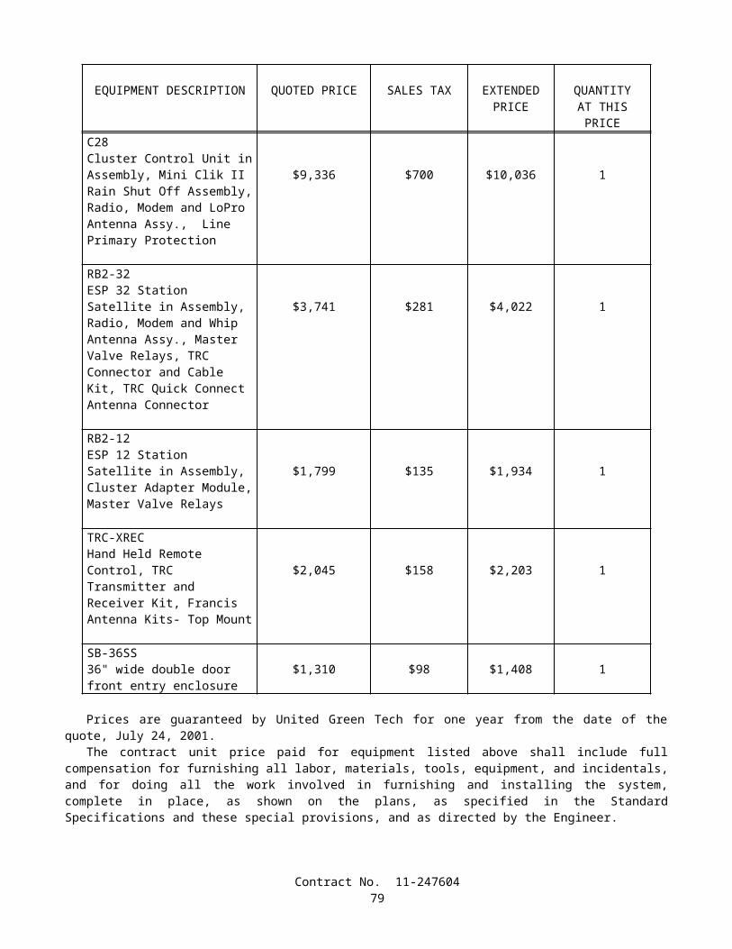
When approved by the Engineer, concrete from trial batches may be used in the work at locations where concrete of a lower quality is required and the concrete will be paid for as the type or class of concrete required at that location.
After materials, mix proportions, mixing equipment, and procedures for concrete have been prequalified for use, additional prequalification by testing of trial batches will be required prior to making changes that, in the judgment of the Engineer, could result in a strength of concrete below that specified.
The Contractor's attention is directed to the time required to test trial batches and the Contractor shall be responsible for production of trial batches at a sufficiently early date so that the progress of the work is not delayed.
When precast concrete members are manufactured at the plant of an established manufacturer of precast concrete members, the mix proportions of the concrete shall be determined by the Contractor, and a trial batch and prequalification of the materials, mix proportions, mixing equipment, and procedures will not be required.
90-10 MINOR CONCRETE
90-10.01 GENERAL Concrete for minor structures, slope paving, curbs, sidewalks and other concrete work, when designated as minor
concrete on the plans, in the specifications, or in the contract item, shall conform to the provisions specified herein. The Engineer, at the Engineer's discretion, will inspect and test the facilities, materials and methods for producing
the concrete to ensure that minor concrete of the quality suitable for use in the work is obtained.
90-10.02 MATERIALS Minor concrete shall conform to the following requirements:
90-10.02A Cementitious Material Cementitious material shall conform to the provisions in Section 90-1.01, "Description."
90-10.02B Aggregate Aggregate shall be clean and free from deleterious coatings, clay balls, roots, and other extraneous materials. The Contractor shall submit to the Engineer for approval, a grading of the combined aggregate proposed for use in
the minor concrete. After acceptance of the grading, aggregate furnished for minor concrete shall conform to that grading, unless a change is authorized in writing by the Engineer.
The Engineer may require the Contractor to furnish periodic test reports of the aggregate grading furnished. The maximum size of aggregate used shall be at the option of the Contractor, but in no case shall the maximum size be larger than 37.5 mm or smaller than 19 mm.
The Engineer may waive, in writing, the gradation requirements in this Section 90-10.02B, if, in the Engineer's opinion, the furnishing of the gradation is not necessary for the type or amount of concrete work to be constructed.
90-10.02C Water Water used for washing, mixing, and curing shall be free from oil, salts, and other impurities that would discolor or
etch the surface or have an adverse affect on the quality of the concrete.
90-10.02D Admixtures The use of admixtures shall conform to the provisions in Section 90-4, "Admixtures."
90-10.03 PRODUCTION Cementitious material, water, aggregate, and admixtures shall be stored, proportioned, mixed, transported, and
discharged in conformance with recognized standards of good practice that will result in concrete that is thoroughly and uniformly mixed, that is suitable for the use intended, and that conforms to requirements specified herein. Recognized standards of good practice are outlined in various industry publications such as are issued by American Concrete Institute, AASHTO, or the Department.
The cementitious material content of minor concrete shall conform to the provisions in Section 90-1.01, "Description."
The amount of water used shall result in a consistency of concrete conforming to the provisions in Section 90 -6.06, "Amount of Water and Penetration." Additional mixing water shall not be incorporated into the concrete during hauling or after arrival at the delivery point, unless authorized by the Engineer.
Discharge of ready-mixed concrete from the transporting vehicle shall be made while the concrete is still plastic and before stiffening occurs. An elapsed time of 1.5 hours (one hour in non-agitating hauling equipment), or more than
Contract No. 11-24760480
250 revolutions of the drum or blades, after the introduction of the cementitious material to the aggregates, or a temperature of concrete of more than 32°C will be considered conditions contributing to the quick stiffening of concrete. The Contractor shall take whatever action is necessary to eliminate quick stiffening, except that the addition of water will not be permitted.
The required mixing time in stationary mixers shall be not less than 50 seconds or more than 5 minutes. The minimum required revolutions at mixing speed for transit-mixed concrete shall be not less than that
recommended by the mixer manufacturer, and shall be increased, if necessary, to produce thoroughly and uniformly mixed concrete.
Each load of ready-mixed concrete shall be accompanied by a weighmaster certificate that shall be delivered to the Engineer at the discharge location of the concrete, unless otherwise directed by the Engineer. The weighmaster certificate shall be clearly marked with the date and time of day when the load left the batching plant and, if hauled in truck mixers or agitators, the time the mixing cycle started.
A Certificate of Compliance conforming to the provisions in Section 6–1.07, "Certificates of Compliance," shall be furnished to the Engineer, prior to placing minor concrete from a source not previously used on the contract, stating that minor concrete to be furnished meets contract requirements, including minimum cementitious material content specified.
90-10.04 CURING MINOR CONCRETE Curing minor concrete shall conform to the provisions in Section 90-7, "Curing Concrete."
90-10.05 PROTECTING MINOR CONCRETE Protecting minor concrete shall conform to the provisions in Section 90-8, "Protecting Concrete," except the
concrete shall be maintained at a temperature of not less than 4°C for 72 hours after placing.
90-10.06 MEASUREMENT AND PAYMENT Minor concrete will be measured and paid for in conformance with the provisions specified in the various sections
of these specifications covering concrete construction when minor concrete is specified in the specifications, shown on the plans, or indicated by contract item in the Engineer's Estimate.
90-11 MEASUREMENT AND PAYMENT
90-11.01 MEASUREMENT Portland cement concrete will be measured in conformance with the provisions specified in the various sections of
these specifications covering construction requiring concrete. When it is provided that concrete will be measured at the mixer, the volume in cubic meters shall be computed as
the total mass of the batch in kilograms divided by the density of the concrete in kilograms per cubic meter. The total mass of the batch shall be calculated as the sum of all materials, including water, entering the batch. The density of the concrete will be determined in conformance with the requirements in California Test 518.
90-11.02 PAYMENT Portland cement concrete will be paid for in conformance with the provisions specified in the various sections of
these specifications covering construction requiring concrete. Full compensation for furnishing and incorporating admixtures required by these specifications or the special
provisions will be considered as included in the contract prices paid for the concrete involved and no additional compensation will be allowed therefor.
Should the Engineer order the Contractor to incorporate any admixtures in the concrete when their use is not required by these specifications or the special provisions, furnishing the admixtures and adding them to the concrete will be paid for as extra work as provided in Section 4-1.03D, "Extra Work."
Should the Contractor use admixtures in conformance with the provisions in Section 90-4.05, "Optional Use of Chemical Admixtures," or Section 90-4.07, "Optional Use of Air-entraining Admixtures," or should the Contractor request and obtain permission to use other admixtures for the Contractor's benefit, the Contractor shall furnish those admixtures and incorporate them into the concrete at the Contractor's expense and no additional compensation will be allowed therefor.
Contract No. 11-24760481