9.17.061 - Bronkhorst
38
Instruction manual EL-FLOW Base series Mass Flow Controllers Doc. no.: 9.17.061L Date: 28-08-2017 ATTENTION Please read this instruction manual carefully before installing and operating the instrument. Not following the guidelines could result in personal injury and/or damage to the equipment.
Transcript of 9.17.061 - Bronkhorst
Instruction manual
EL-FLOW Base series Mass Flow Controllers
Doc. no.: 9.17.061L Date: 28-08-2017
ATTENTION Please read this instruction manual carefully before installing and operating the instrument. Not following the guidelines could result in personal injury and/or damage to the equipment.

BRONKHORST®
Page 2 EL-FLOW Base Series Mass Flow Controllers 9.17.061
Even though care has been taken in the preparation and publication of the contents of this manual, we do not
assume legal or other liability for any inaccuracy, mistake, mis-statement or any other error of whatsoever nature
contained herein. The material in this manual is for information purposes only, and is subject to change
without notice.
BRONKHORST®
9.17.061 EL-FLOW Base Series Mass Flow Controllers Page 3
TABLE OF CONTENTS
1 General Product Information ........................................................................................................... 4 1.1 Introduction ....................................................................................................................................................... 4 1.2 Intended Use ...................................................................................................................................................... 4 1.3 Symbols .............................................................................................................................................................. 4 1.4 Product Support References .............................................................................................................................. 4 1.5 Warranty ............................................................................................................................................................ 5 1.6 Product Description ........................................................................................................................................... 5 1.7 Operating Principles ........................................................................................................................................... 8 1.8 Maintenance ...................................................................................................................................................... 9
2 Installation Instructions ................................................................................................................. 10 2.1 Introduction ..................................................................................................................................................... 10 2.2 Unpacking and inspection ................................................................................................................................ 10 2.3 Rated pressure test inspection ........................................................................................................................ 10 2.4 Instrument mounting ....................................................................................................................................... 10 2.5 Fluidic connections .......................................................................................................................................... 11 2.6 In-line filter usage ............................................................................................................................................ 11 2.7 Piping requirements ........................................................................................................................................ 11 2.8 Electrical connections ...................................................................................................................................... 12 2.9 Power and warm-up ........................................................................................................................................ 12 2.10 Pressure supply / Start-up ............................................................................................................................... 12 2.11 System purging ................................................................................................................................................ 13 2.12 Zeroing ............................................................................................................................................................. 13
3 Basic Operation ............................................................................................................................. 14 3.1 General ............................................................................................................................................................ 14 3.2 Analog operation ............................................................................................................................................. 14 3.3 Digital communication protocol detection (Flow-BUS RS232 or MODBUS RS485) ......................................... 15 3.4 Basic RS232 Flowbus operation ....................................................................................................................... 16 3.5 Modbus RS485 operation ................................................................................................................................ 17 3.6 Push-button operation .................................................................................................................................... 24 3.7 Micro-switch use for reading/changing control mode .................................................................................... 25 3.8 LED indications ................................................................................................................................................. 26 3.9 Basic Parameters and Properties ..................................................................................................................... 27
4 Advanced Operation ..................................................................................................................... 29 4.1 Reading and Changing Instrument Parameters ............................................................................................... 29 4.2 Using other gasses than specified .................................................................................................................... 34
5 Troubleshooting ............................................................................................................................ 35 5.1 General ............................................................................................................................................................ 35 5.2 LED indications ................................................................................................................................................. 35 5.3 Troubleshooting summary general .................................................................................................................. 35
6 Removal and Return Instructions ................................................................................................... 37 7 Service .......................................................................................................................................... 38
BRONKHORST®
Page 4 EL-FLOW Base Series Mass Flow Controllers 9.17.061
1 General Product Information
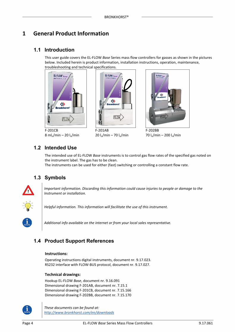
1.1 Introduction This user guide covers the EL-FLOW Base Series mass flow controllers for gasses as shown in the pictures below. Included herein is product information, installation instructions, operation, maintenance, troubleshooting and technical specifications.
F-201CB F-201AB F-202BB 8 mln/min – 20 ln/min 20 ln/min – 70 ln/min 70 ln/min – 200 ln/min
1.2 Intended Use The intended use of EL-FLOW Base instruments is to control gas flow rates of the specified gas noted on the instrument label. The gas has to be clean. The instruments can be used for either (fast) switching or controlling a constant flow rate.
1.3 Symbols
Important information. Discarding this information could cause injuries to people or damage to the Instrument or installation.
Helpful information. This information will facilitate the use of this instrument.
Additional info available on the internet or from your local sales representative.
1.4 Product Support References
Instructions: Operating instructions digital instruments, document nr. 9.17.023. RS232 interface with FLOW-BUS protocol, document nr. 9.17.027.
Technical drawings: Hookup EL-FLOW Base, document nr. 9.16.091 Dimensional drawing F-201AB, document nr. 7.15.1 Dimensional drawing F-201CB, document nr. 7.15.166 Dimensional drawing F-202BB, document nr. 7.15.170
These documents can be found at: http://www.bronkhorst.com/en/downloads
BRONKHORST®
9.17.061 EL-FLOW Base Series Mass Flow Controllers Page 5
1.5 Warranty The products of Bronkhorst® are warranted against defects in material and workmanship for a period of three years from the date of shipment, provided they are used in accordance with the ordering specifications and the instructions in this manual and that they are not subjected to abuse, physical damage or contamination. Products that do not operate properly during this period may be repaired or replaced at no charge. Repairs are normally warranted for one year or the balance of the original warranty, whichever is the longer. See also paragraph 9 of the Conditions of sales. The warranty includes all initial and latent defects, random failures, and undeterminable internal causes. It excludes failures and damage caused by the customer, such as contamination, improper electrical hook-up, physical shock etc. Re-conditioning of products primarily returned for warranty service that is partly or wholly judged non-warranty may be charged for. Bronkhorst High-Tech B.V. prepays outgoing freight charges when any party of the service is performed under warranty, unless otherwise agreed upon beforehand, however, if the product has been returned collect to Bronkhorst High-Tech B.V., these costs are added to the repair invoice. Import and/or export charges, foreign shipping methods/carriers are paid for by the customer.
1.6 Product Description
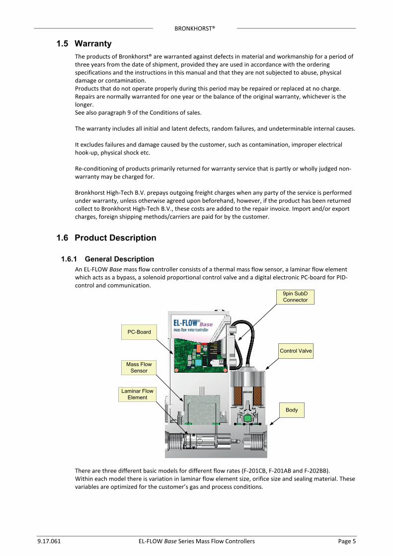
1.6.1 General Description An EL-FLOW Base mass flow controller consists of a thermal mass flow sensor, a laminar flow element which acts as a bypass, a solenoid proportional control valve and a digital electronic PC-board for PID-control and communication.
PC-Board
Mass Flow Sensor
Laminar Flow Element
9pin SubD Connector
Control Valve
Body
There are three different basic models for different flow rates (F-201CB, F-201AB and F-202BB). Within each model there is variation in laminar flow element size, orifice size and sealing material. These variables are optimized for the customer’s gas and process conditions.
BRONKHORST®
Page 6 EL-FLOW Base Series Mass Flow Controllers 9.17.061
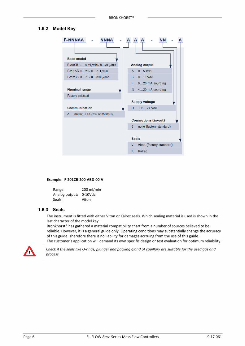
1.6.2 Model Key Example: F-201CB-200-ABD-00-V
Range: 200 ml/min Analog output: 0-10Vdc Seals: Viton
1.6.3 Seals The instrument is fitted with either Viton or Kalrez seals. Which sealing material is used is shown in the last character of the model key. Bronkhorst® has gathered a material compatibility chart from a number of sources believed to be reliable. However, it is a general guide only. Operating conditions may substantially change the accuracy of this guide. Therefore there is no liability for damages accruing from the use of this guide. The customer’s application will demand its own specific design or test evaluation for optimum reliability.
Check if the seals like O-rings, plunger and packing gland of capillary are suitable for the used gas and process.
BRONKHORST®
9.17.061 EL-FLOW Base Series Mass Flow Controllers Page 7
1.6.4 Calibration EL-FLOW Base instruments are Air or N2 calibrated. Bronkhorst® certifies that all instruments meet the rated accuracy. They have been calibrated using measurement standards traceable to the standards of the Dutch Metrology Institute (VSL). The calibration is converted to the customer’s gas and conditions using a detailed conversion model. This conversion adds a level of calibration uncertainty. Thumb rule for calculating the conversion uncertainty is typical: Uncertainty < 2% x CF for CF > 1 Uncertainty < 2% / CF for CF < 1 With CF defined as the approximate conversion factor, which can be calculated with:
2
1
2
1
ρρ⋅
⋅=
p
p
CC
CF
in which:
npC specific heat
nρ density at normal conditions (1) calibration fluid (Air or N2) (2) customer fluid
Check FLUIDAT® on http://www.fluidat.com FLUIDAT® is a collection of routines to calculate physical properties of gases and liquids. These routines are made available at the FLUIDAT® on the Net website.
EL-FLOW Base instruments are standard delivered without calibration certificate. Calibration certificates can be ordered together with the instruments. Contact your local sales representative for more information.
1.6.5 Features Each instrument consists of an Analog interface, a digital RS-232 interface and a digital ModBus/RS485 interface. The analog and the digital interface can be used together at the same time. According to the pin-designation both RS232 and Modbus/RS485 are assigned to the same pins. When connecting these pins to either of the two, the instrument will automatically detect which protocol to use. Digital operation adds a lot of extra features (compared to analog operation) to the instruments. Such as: • setpoint slope (ramp function on setpoint for smooth control) • direct reading at readout/control module or host computer • several control/setpoint modes (e.g. purge/close valve) • identification (serial number, model number, device type, user tag) • adjustable controller settings for custom controller response
BRONKHORST®
Page 8 EL-FLOW Base Series Mass Flow Controllers 9.17.061
1.7 Operating Principles
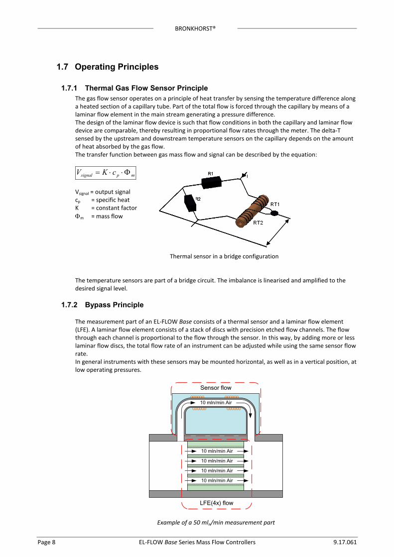
1.7.1 Thermal Gas Flow Sensor Principle The gas flow sensor operates on a principle of heat transfer by sensing the temperature difference along a heated section of a capillary tube. Part of the total flow is forced through the capillary by means of a laminar flow element in the main stream generating a pressure difference. The design of the laminar flow device is such that flow conditions in both the capillary and laminar flow device are comparable, thereby resulting in proportional flow rates through the meter. The delta-T sensed by the upstream and downstream temperature sensors on the capillary depends on the amount of heat absorbed by the gas flow. The transfer function between gas mass flow and signal can be described by the equation:
mpsignal cKV Φ⋅⋅=
Vsignal = output signal cp = specific heat K = constant factor Φm = mass flow
Thermal sensor in a bridge configuration
The temperature sensors are part of a bridge circuit. The imbalance is linearised and amplified to the desired signal level.
1.7.2 Bypass Principle The measurement part of an EL-FLOW Base consists of a thermal sensor and a laminar flow element (LFE). A laminar flow element consists of a stack of discs with precision etched flow channels. The flow through each channel is proportional to the flow through the sensor. In this way, by adding more or less laminar flow discs, the total flow rate of an instrument can be adjusted while using the same sensor flow rate. In general instruments with these sensors may be mounted horizontal, as well as in a vertical position, at low operating pressures.
Sensor flow
10 mln/min Air
LFE(4x) flow
10 mln/min Air
10 mln/min Air
10 mln/min Air
10 mln/min Air
Example of a 50 mln/min measurement part
BRONKHORST®
9.17.061 EL-FLOW Base Series Mass Flow Controllers Page 9
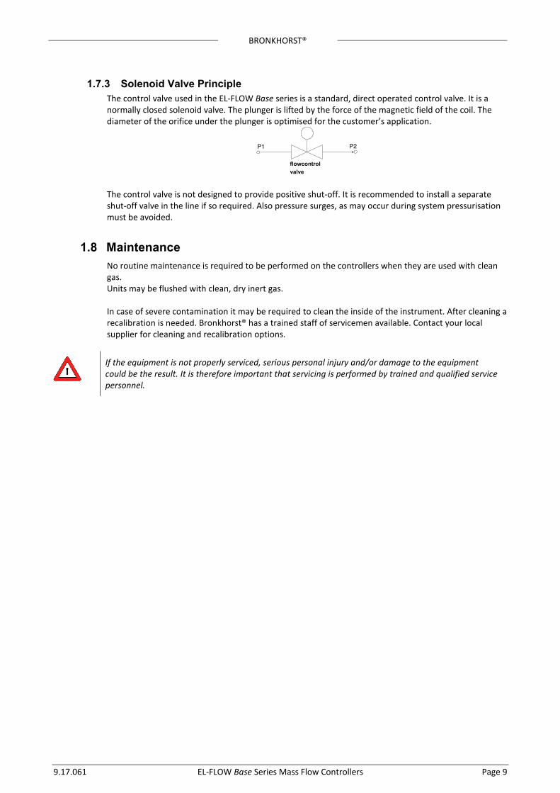
1.7.3 Solenoid Valve Principle The control valve used in the EL-FLOW Base series is a standard, direct operated control valve. It is a normally closed solenoid valve. The plunger is lifted by the force of the magnetic field of the coil. The diameter of the orifice under the plunger is optimised for the customer’s application.
flowcontrol valve
The control valve is not designed to provide positive shut-off. It is recommended to install a separate shut-off valve in the line if so required. Also pressure surges, as may occur during system pressurisation must be avoided.
1.8 Maintenance No routine maintenance is required to be performed on the controllers when they are used with clean gas. Units may be flushed with clean, dry inert gas. In case of severe contamination it may be required to clean the inside of the instrument. After cleaning a recalibration is needed. Bronkhorst® has a trained staff of servicemen available. Contact your local supplier for cleaning and recalibration options.
If the equipment is not properly serviced, serious personal injury and/or damage to the equipment could be the result. It is therefore important that servicing is performed by trained and qualified service personnel.
BRONKHORST®
Page 10 EL-FLOW Base Series Mass Flow Controllers 9.17.061
2 Installation Instructions
2.1 Introduction This chapter discusses how to prepare the system and install an EL-FLOW Base mass flow controller.
2.2 Unpacking and inspection Check the outside packing box for damage incurred during shipment. Should the packing box be damaged, then the local carrier must be notified at once regarding his liability, if so required. At the same time a report should be submitted to your distributor. Carefully remove the equipment from the packing box. Verify that the equipment was not damaged during shipment. Should the equipment be damaged, then the local carrier must be notified at once regarding his liability, if so required. At the same time a report should be submitted to your distributor. Refer to chapter 6, Removal and Return Instructions, about return shipment procedures.
Before installing an EL-FLOW Base it is important to read the attached label and check: - Flow rate - Fluid to be measured - Up- and downstream pressures - Input/output signal - Temperature Do not discard spare or replacement parts with the packing material and inspect the contents for damaged or missing parts.
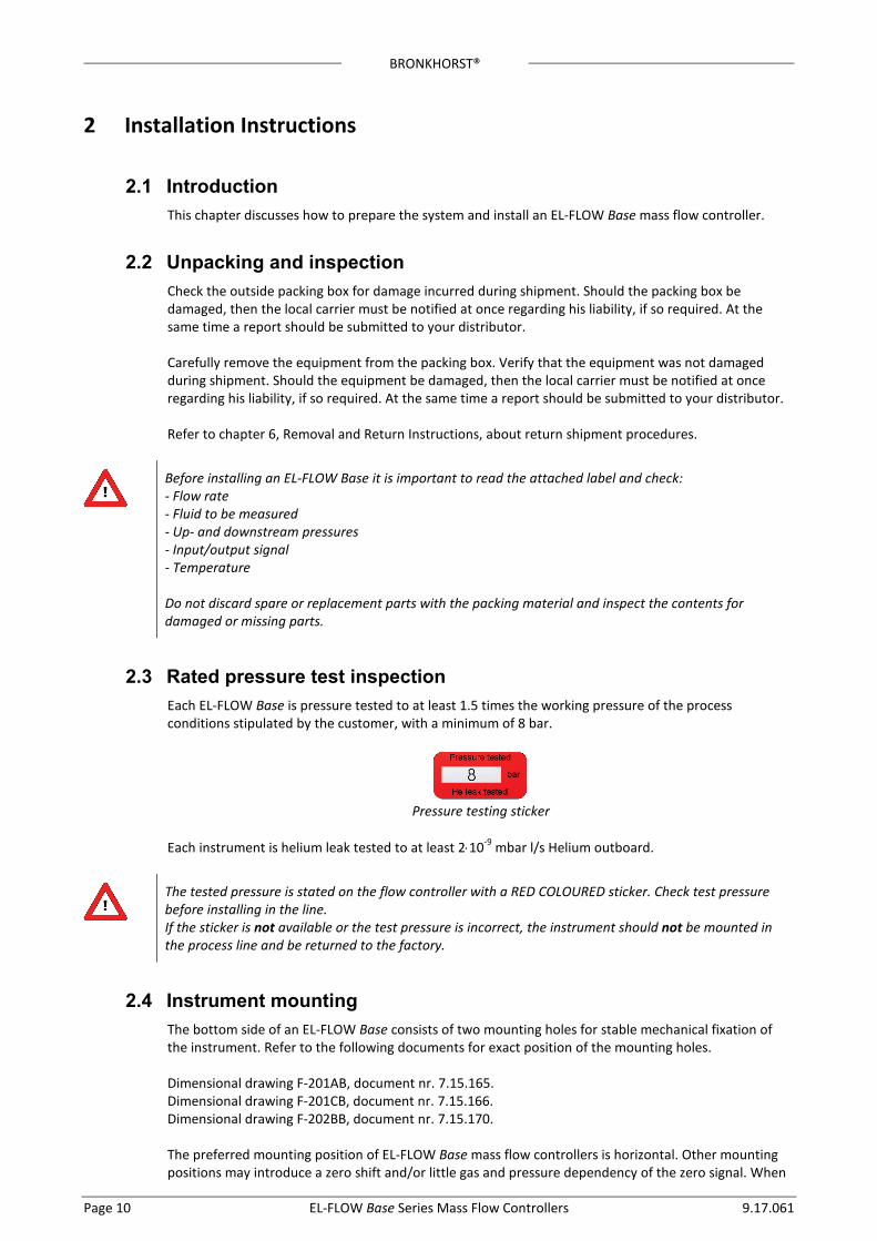
2.3 Rated pressure test inspection Each EL-FLOW Base is pressure tested to at least 1.5 times the working pressure of the process conditions stipulated by the customer, with a minimum of 8 bar.
Pressure testing sticker
Each instrument is helium leak tested to at least 2⋅10-9 mbar l/s Helium outboard.
The tested pressure is stated on the flow controller with a RED COLOURED sticker. Check test pressure before installing in the line. If the sticker is not available or the test pressure is incorrect, the instrument should not be mounted in the process line and be returned to the factory.
2.4 Instrument mounting The bottom side of an EL-FLOW Base consists of two mounting holes for stable mechanical fixation of the instrument. Refer to the following documents for exact position of the mounting holes. Dimensional drawing F-201AB, document nr. 7.15.165. Dimensional drawing F-201CB, document nr. 7.15.166. Dimensional drawing F-202BB, document nr. 7.15.170. The preferred mounting position of EL-FLOW Base mass flow controllers is horizontal. Other mounting positions may introduce a zero shift and/or little gas and pressure dependency of the zero signal. When
BRONKHORST®
9.17.061 EL-FLOW Base Series Mass Flow Controllers Page 11
mounting an instrument other than horizontal, zeroing of the instrument is advised. The zeroing procedure is described in chapter 2.12. Avoid installation in close proximity of mechanic vibration and/or heat sources.
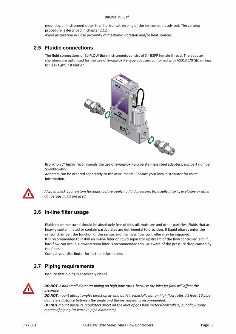
2.5 Fluidic connections The fluid connections of EL-FLOW Base instruments consist of ¼” BSPP female thread. The adapter chambers are optimised for the use of Swagelok RS-type adapters combined with AS013 (70°Sh) o-rings for leak tight installation.
Bronkhorst® highly recommends the use of Swagelok RS-type stainless steel adapters, e.g. part number SS-400-1-4RS. Adapters can be ordered separately to the instruments. Contact your local distributor for more information.
Always check your system for leaks, before applying fluid pressure. Especially if toxic, explosive or other dangerous fluids are used.
2.6 In-line filter usage Fluids to be measured should be absolutely free of dirt, oil, moisture and other particles. Fluids that are heavily contaminated or contain particulates are detrimental to precision. If liquid phases enter the sensor chamber, the function of the sensor and the mass flow controller may be impaired. It is recommended to install an in-line filter or liquid separator upstream of the flow controller, and if backflow can occur, a downstream filter is recommended too. Be aware of the pressure drop caused by the filter. Contact your distributor for further information.
2.7 Piping requirements Be sure that piping is absolutely clean!
DO NOT install small diameter piping on high flow rates, because the inlet jet flow will affect the accuracy. DO NOT mount abrupt angles direct on in- and outlet, especially not on high flow rates. At least 10 pipe diameters distance between the angle and the instrument is recommended. DO NOT mount pressure regulators direct on the inlet of gas flow meters/controllers, but allow some meters of piping (at least 25 pipe diameters).
BRONKHORST®
Page 12 EL-FLOW Base Series Mass Flow Controllers 9.17.061
2.8 Electrical connections
2.8.1 Interface EL-FLOW Base instruments can be operated by means of:
1. Analog interface (0...5Vdc or 0...10Vdc or 0...20mA or 4...20mA) 2. RS232 interface with FLOW-BUS protocol 3. RS485 interface with Modbus protocol
All above operation options are standard available in EL-FLOW Base instruments. According to the pin-designation both RS232 and RS485 are assigned to the same pins. When connecting these pins to either of the two, the instrument will automatically detect which protocol to use. When sending a frequent request to the instrument, it will be capable of recognising the protocol, once the instrument detect this protocol, it will send an answer. The instrument will remember the detected protocol as long as the instrument is powered. This auto detection can not be switched off or by-passed. For electrical hook-up diagrams refer to document 9.16.091, “Hook-up EL-FLOW Base”
This documents can be found at: http://www.bronkhorst.com/en/downloads
2.8.2 Power Supply EL-FLOW Base controllers are powered with +15 Vdc to +24 Vdc. When providing your own power supply be sure that voltage and current rating are according to the specifications of the instrument(s) and furthermore that the source is capable of delivering enough power to the instrument(s). Refer to Hookup EL-FLOW Base, document nr. 9.16.091, for more details. Bronkhorst® recommends the use of their standard cables. These cables have the right connectors and if loose ends are used, these will be marked to prevent wrong connection. When using other cables, cable wire diameters should be sufficient to carry the supply current and voltage losses must be kept as low as possible. When in doubt: contact your distributor. EL-FLOW Base instruments carry the CE-mark. Therefore they have to comply with the EMC requirements as are valid for these instruments. However compliance with the EMC requirements is not possible without the use of proper cables and connector/gland assemblies.
!
When connecting the system to other devices (e.g. to PLC), be sure that the integrity of the shielding is not affected. Do not use unshielded wire terminals.
2.9 Power and warm-up Before switching on power, check if all connections have been made according to the hook-up diagram. It is recommended to turn on power before applying pressure on the instrument and to switch off power after removing pressure.Check fluid connections and make sure there is no leakage. If needed purge the system with a proper fluid. Only purging with gases is allowed. Turn on power and allow at least 30 minutes warming up and stabilizing. During warm-up period, fluid pressure may either be on or off.
2.10 Pressure supply / Start-up When applying pressure to the system, take care to avoid pressure shocks in the system and increase pressure gradually up to the level of the actual operating conditions.
BRONKHORST®
9.17.061 EL-FLOW Base Series Mass Flow Controllers Page 13
2.11 System purging If explosive gases are to be used, purge the process with inert dry gas like Nitrogen, Argon etc. for at least 30 minutes. In systems with corrosive or reactive fluids, purging with an inert gas is absolutely necessary, because if the tubing has been exposed to air, introducing these fluids will tend to clog up or corrode the system due to a chemical reaction with oxygen or moist air. Complete purging is also required to remove such fluids from the system before exposing the system to air. It is preferred not to expose the system to air, when working with these corrosive fluids.
2.12 Zeroing The zero point of each instrument is factory adjusted. However, the zero point may shift slightly due to temperature, pressure, gas type and mounting position influences. If so required, the zero point of the instrument may be re-adjusted. Zeroing is possible over RS232 Flowbus, RS485 ModBus or by means of using the micro switch. Zeroing by means of using the micro switch is described in this manual. • Warm-up, pressure up the system and fill the instrument according to the process conditions. • Make sure no flow is going through the instrument by closing valves near the instrument. • The setpoint must be zero. • Press the micro switch and hold it. After a short time the red LED will go ON and OFF, then the green
LED will go ON. At that moment release the micro switch. • The zeroing procedure will start at that moment and the green LED will blink fast. The zeroing
procedure waits for a stable signal and saves the zero. If the signal is not stable zeroing will take long and the nearest point to zero is accepted. The procedure will take approx. 10 sec.
• When indication is showing 0% signal and the green indication LED is burning continuously again, then zero has been performed well.
For information how to start the zeroing procedure over RS232 FlowBus or RS485 ModBus check chapter 4.1.4, “Auto Zeroing”
BRONKHORST®
Page 14 EL-FLOW Base Series Mass Flow Controllers 9.17.061
3 Basic Operation
3.1 General An EL-FLOW base instrument can be operated by means of: • Analog interface (0...5Vdc/0...10Vdc/0...20mA/4...20mA) • Digital RS232 Flowbus interface (connected to COM-port by means of special cable on 38400 Baud) • Digital RS485 Modbus interface. Operation via analog or digital interface can be performed at the same time. A special parameter called “control mode” indicates to which setpoint the controller should respond.
3.2 Analog operation At analog operation following signals are available: • measured value (analog output) • setpoint (analog input) The type of installed analog interface (0-5V, 0-10V, 0-20mA or 4-20mA) can be found in the model key of the instrument. Refer to paragraph 1.6.2. Setpoints below 2% of the full scale will be interpreted as 0% setpoint.
When operating the instrument through the analog interface it is possible to connect the instrument simultaneously to RS232 or Modbus/RS485 for reading/changing parameters (e.g. controller response or other fluid selection).
BRONKHORST®
9.17.061 EL-FLOW Base Series Mass Flow Controllers Page 15
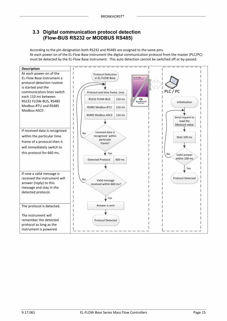
3.3 Digital communication protocol detection (Flow-BUS RS232 or MODBUS RS485)
According to the pin-designation both RS232 and RS485 are assigned to the same pins. At each power-on of the EL-Flow Base instrument the digital communication protocol from the master (PLC/PC) must be detected by the EL-Flow Base instrument. This auto detection cannot be switched off or by-passed.
Description
PLC / PCPLC / PC
Valid answer within 100 ms
No
Initialisation
Send request to read the
Measure value
Protocol Detected
Yes
Wait 100 ms
BronkhorstHIGH-TECH
R
Ruu
rlo -
Hol
lMnd
BMseEI-FIOWmass flow meter/controller
received data is recognized within
particular frame?
No
Valid message received within 660 ms?
Protocol Detectionin EL-FLOW Base
RS232 FLOW-BUS 110 ms
RS485 Modbus-RTU 110 ms
RS485 Modbus-ASCII 110 ms
Protocol and time frame (ms)
Detected Protocol 660 ms
Yes
Protocol Detected
Yes
No
Answer is sent
At each power-on of the EL-Flow Base instrument a protocol detection routine is started and the communication lines switch each 110 ms between RS232 FLOW-BUS, RS485 Modbus-RTU and RS485 Modbus-ASCII .
If received data is recognized within the particular time frame of a protocol then it will immediately switch to this protocol for 660 ms.
If now a valid message is received the instrument will answer (reply) to this message and stay in the detected protocol.
The protocol is detected. The instrument will remember the detected protocol as long as the instrument is powered.
BRONKHORST®
Page 16 EL-FLOW Base Series Mass Flow Controllers 9.17.061
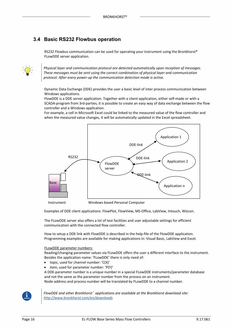
3.4 Basic RS232 Flowbus operation RS232 Flowbus communication can be used for operating your instrument using the Bronkhorst® FLowDDE server application.
Physical layer and communication protocol are detected automatically upon reception of messages. These messages must be sent using the correct combination of physical layer and communication protocol. After every power-up the communication detection mode is active.
Dynamic Data Exchange (DDE) provides the user a basic level of inter process communication between Windows applications. FlowDDE is a DDE server application. Together with a client-application, either self-made or with a SCADA-program from 3rd-parties, it is possible to create an easy way of data exchange between the flow controller and a Windows application. For example, a cell in Microsoft Excel could be linked to the measured value of the flow controller and when the measured value changes, it will be automatically updated in the Excel spreadsheet.
Examples of DDE client applications: FlowPlot, FlowView, MS-Office, LabView, Intouch, Wizcon. The FLowDDE server also offers a lot of test facilities and user adjustable settings for efficient communication with the connected flow controller. How to setup a DDE link with FlowDDE is described in the help-file of the FlowDDE application. Programming examples are available for making applications in: Visual Basic, LabView and Excel. FLowDDE parameter numbers: Reading/changing parameter values via FLowDDE offers the user a different interface to the instrument. Besides the application name: ‘FLowDDE’ there is only need of: • topic, used for channel number: ‘C(X)’ • item, used for parameter number: ‘P(Y)’ A DDE-parameter number is a unique number in a special FLowDDE instruments/parameter database and not the same as the parameter number from the process on an instrument. Node-address and process number will be translated by FLowDDE to a channel number.
FlowDDE and other Bronkhorst® applications are available at the Bronkhorst download site: http://www.bronkhorst.com/en/downloads
Base
FlowDDE server
Application 1
Application 2
Application n
RS232
DDE-link
DDE-link
DDE-link
Windows based Personal Computer Instrument
BRONKHORST®
9.17.061 EL-FLOW Base Series Mass Flow Controllers Page 17
A special RS232 cable (7.03.366) can be ordered separately. It consists of a T-part with 1 male and 1 female sub-D 9 connector on one instrument-side and a normal female sub-D 9 connector on the side of the computer. By means of this cable it is possible to offer RS232 communication and still be able to connect power-supply and analog interface through the (analog) sub-D 9 connector.
3.5 Modbus RS485 operation This chapter is limited to the description of the interface between the Modbus Mass Flow Controller with a master device. It will explain how to install an EL-FLOW Base instrument to your Modbus system. It only contains the information that is needed most. The implementation of the Modbus interface is based on the following standards: [1] MODBUS Application Protocol Specification V1.1b, December 28, 2006 [2] MODBUS over Serial Line specification and implementation guide V1.02 There is no mutual communication between Modbus slaves; only between master and slave.
More detailed information about Modbus can be found at http://www.modbus.org or any website of the (local) Modbus organisation of your country (when available).
Physical layer and communication protocol are detected automatically upon reception of messages. These messages must be sent using the correct combination of physical layer and communication protocol. After every power-up the communication detection mode is active.
3.5.1 Slave address, baud rate and parity setup Default instruments will be delivered to customers on address 1 and with a baud rate of 19200 baud and EVEN parity.
The slave address, baud rate and parity of the Bronkhorst® meter/controller Modbus slave can be changed to fit the instrument in your existing Modbus network. Changing the slave address, baud rate and parity can be done in the following ways.
Using RS232: FlowDDE ‘Off-line’ via the RS232 communication port by means of FlowDDE. This program can be used to read/change parameters, including the slave address, baud rate and parity. Connect your Bronkhorst® meter/controller Modbus slave instrument to a free COM-port using the special cable with on one side a T-part with male and female sub-D 9 connector and on the other side a female sub-D 9 connector (part number 7.03.366). The single sub-D 9 connector should be connected to your COM-port and the female sub-D 9 of the T-part to the male sub-D 9 of the instrument. Standard cables are approx. 3 meters. Maximum length between PC and instrument allowed is approximately 10 meters. Start FlowDDE and open communication via the menu (as shown below) or by pressing <F3>.
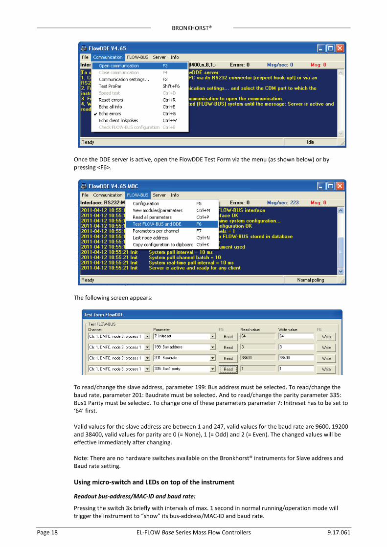
BRONKHORST®
Page 18 EL-FLOW Base Series Mass Flow Controllers 9.17.061
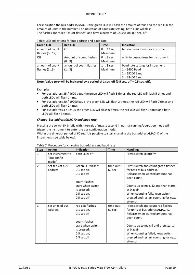
Once the DDE server is active, open the FlowDDE Test Form via the menu (as shown below) or by pressing <F6>.
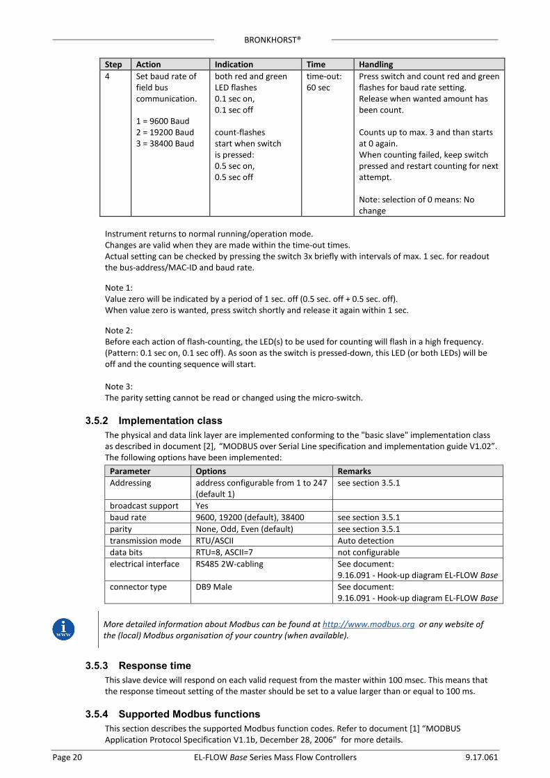
The following screen appears:
To read/change the slave address, parameter 199: Bus address must be selected. To read/change the baud rate, parameter 201: Baudrate must be selected. And to read/change the parity parameter 335: Bus1 Parity must be selected. To change one of these parameters parameter 7: Initreset has to be set to ‘64’ first. Valid values for the slave address are between 1 and 247, valid values for the baud rate are 9600, 19200 and 38400, valid values for parity are 0 (= None), 1 (= Odd) and 2 (= Even). The changed values will be effective immediately after changing. Note: There are no hardware switches available on the Bronkhorst® instruments for Slave address and Baud rate setting.
Using micro-switch and LEDs on top of the instrument
Readout bus-address/MAC-ID and baud rate:
Pressing the switch 3x briefly with intervals of max. 1 second in normal running/operation mode will trigger the instrument to “show” its bus-address/MAC-ID and baud rate.
BRONKHORST®
9.17.061 EL-FLOW Base Series Mass Flow Controllers Page 19
For indication the bus-address/MAC-ID the green LED will flash the amount of tens and the red LED the amount of units in the number. For indication of baud rate setting, both LEDs will flash. The flashes are called “count-flashes” and have a pattern of 0.5 sec. on, 0.5 sec. off. Table: LED indications for bus-address and baud rate Green LED Red LED Time Indication amount of count flashes (0...12)
Off 0 ... 12 sec. Maximum
tens in bus-address for instrument
Off Amount of count flashes (0...9)
0 ... 9 sec. Maximum
units in bus-address for instrument
amount of count flashes (1...3)
amount of count flashes (1...3)
1 ... 3 sec. Maximum
baud rate setting for instrument 1 = 9600 Baud 2 = 19200 Baud 3 = 38400 Baud
Note: Value zero will be indicated by a period of 1 sec. off (0.5 sec. off + 0.5 sec. off). Examples: • For bus-address 35 / 9600 baud the green LED will flash 3 times, the red LED will flash 5 times and
both LEDs will flash 1 time. • For bus-address 20 / 19200 baud the green LED will flash 2 times, the red LED will flash 0 times and
both LEDs will flash 2 times. • For bus-address 3 / 38400 the green LED will flash 0 times, the red LED will flash 3 times and both
LEDs will flash 3 times.
Change bus-address/MAC-ID and baud rate:
Pressing the switch 5x briefly with intervals of max. 1 second in normal running/operation mode will trigger the instrument to enter the bus configuration mode. Within the time-out period of 60 sec. it is possible to start changing the bus-address/MAC-ID of the instrument (see table below). Table 7: Procedure for changing bus-address and baud rate Step Action Indication Time Handling 1 Set instrument to
“bus config mode”
both LEDs off Press switch 5x briefly
2 Set tens of bus- address
Green LED flashes 0.1 sec on, 0.1 sec off count-flashes start when switch is pressed: 0.5 sec on, 0.5 sec off
time-out: 60 sec
Press switch and count green flashes for tens of bus-address. Release when wanted amount has been count. Counts up to max. 12 and than starts at 0 again. When counting fails, keep switch pressed and restart counting for next attempt.
3 Set units of bus- Address
red LED flashes 0.1 sec on, 0.1 sec off count-flashes start when switch is pressed: 0.5 sec on, 0.5 sec off
time-out: 60 sec
Press switch and count red flashes for units of bus-address/MAC-ID. Release when wanted amount has been count. Counts up to max. 9 and then starts at 0 again. When counting failed, keep switch pressed and restart counting for next attempt.
BRONKHORST®
Page 20 EL-FLOW Base Series Mass Flow Controllers 9.17.061
Step Action Indication Time Handling 4 Set baud rate of
field bus communication. 1 = 9600 Baud 2 = 19200 Baud 3 = 38400 Baud
both red and green LED flashes 0.1 sec on, 0.1 sec off count-flashes start when switch is pressed: 0.5 sec on, 0.5 sec off
time-out: 60 sec
Press switch and count red and green flashes for baud rate setting. Release when wanted amount has been count. Counts up to max. 3 and than starts at 0 again. When counting failed, keep switch pressed and restart counting for next attempt. Note: selection of 0 means: No change
Instrument returns to normal running/operation mode. Changes are valid when they are made within the time-out times. Actual setting can be checked by pressing the switch 3x briefly with intervals of max. 1 sec. for readout the bus-address/MAC-ID and baud rate. Note 1: Value zero will be indicated by a period of 1 sec. off (0.5 sec. off + 0.5 sec. off). When value zero is wanted, press switch shortly and release it again within 1 sec. Note 2: Before each action of flash-counting, the LED(s) to be used for counting will flash in a high frequency. (Pattern: 0.1 sec on, 0.1 sec off). As soon as the switch is pressed-down, this LED (or both LEDs) will be off and the counting sequence will start. Note 3: The parity setting cannot be read or changed using the micro-switch.
3.5.2 Implementation class The physical and data link layer are implemented conforming to the "basic slave" implementation class as described in document [2], “MODBUS over Serial Line specification and implementation guide V1.02”. The following options have been implemented:
More detailed information about Modbus can be found at http://www.modbus.org or any website of the (local) Modbus organisation of your country (when available).
3.5.3 Response time This slave device will respond on each valid request from the master within 100 msec. This means that the response timeout setting of the master should be set to a value larger than or equal to 100 ms.
3.5.4 Supported Modbus functions This section describes the supported Modbus function codes. Refer to document [1] “MODBUS Application Protocol Specification V1.1b, December 28, 2006” for more details.
Parameter Options Remarks Addressing address configurable from 1 to 247
(default 1) see section 3.5.1
broadcast support Yes baud rate 9600, 19200 (default), 38400 see section 3.5.1 parity None, Odd, Even (default) see section 3.5.1 transmission mode RTU/ASCII Auto detection data bits RTU=8, ASCII=7 not configurable electrical interface RS485 2W-cabling See document:
9.16.091 - Hook-up diagram EL-FLOW Base connector type DB9 Male See document:
9.16.091 - Hook-up diagram EL-FLOW Base
BRONKHORST®
9.17.061 EL-FLOW Base Series Mass Flow Controllers Page 21
More detailed information about Modbus can be found at http://www.modbus.org or any website of the (local) Modbus organisation of your country (when available).
Read Holding Registers (03)
Possible exception responses: • 02, ILLEGAL DATA ADDRESS, in case of reading of non-existing address, or reading a part of a
multiregister parameter (float, long, etc) • 03, ILLEGAL DATA VALUE, in case of reading less than 1 or more than 125 registers • 04, SLAVE DEVICE FAILURE, in case of reading a write-only register
!
The maximum message size for the Read Holding Registers function is 100 bytes at 9600 baud (200 bytes at 19200 baud and 400 bytes at 38400 baud). When this size is exceeded, corrupted responses may be received.
Write Single Register (06)
Possible exception responses: • 02, ILLEGAL DATA ADDRESS, in case of writing to non-existing address, or writing to a part of a
multiregister parameter (float, long, etc) • 04, SLAVE DEVICE FAILURE, in case of writing to read-only register • 04, SLAVE DEVICE FAILURE, in case of writing illegal value to register
Write Multiple Registers (16)
Possible exception responses: • 02, ILLEGAL DATA ADDRESS, in case of writing to non-existing address, or writing to a part of a
multiregister parameter (float, long, etc) • 03, ILLEGAL DATA VALUE, in case of reading less than 1 or more than 123 registers • 04, SLAVE DEVICE FAILURE, in case of writing to read-only register • 04, SLAVE DEVICE FAILURE, in case of writing illegal value to register When one of the written registers raises an exception, the value written to all subsequent registers are discarded (ignored).
Diagnostics (08)
The following sub-functions are supported: Sub-function code (dec) Name 00 Return Query Data 10 Clear Counters and Diagnostics Register 11 Return Bus Message Count 12 Return Bus Communication Error Count 13 Return Bus Exception Error Count 14 Return Slave Message Count 15 Return Slave No Response Count 16 Return Slave NAK Count (always 0) 17 Return Slave Busy Count (always 0) 18 Return Bus Character Overrun Count
!
The maximum message size for the Return Query Data sub function is 100 bytes at 9600 baud (200 bytes at 19200 baud and 400 bytes at 38400 baud). When this size is exceeded, corrupted responses may be received.
Possible exception responses: • 01, ILLEGAL FUNCTION, in case of not-supported sub-function • 03, ILLEGAL DATA VALUE, in case of an incorrect value for the data field
BRONKHORST®
Page 22 EL-FLOW Base Series Mass Flow Controllers 9.17.061
Report Slave ID (17)
The Slave ID field in the response is a string with the same contents as FlowDDE parameter 1 (indent number + version nr/serial nr). The Run Indicator Status field in this message will indicate ON when the device is in normal operating mode (FB_NORMAL). Possible exception responses: • 04, SLAVE DEVICE FAILURE, in case of an internal error
3.5.5 Available parameters Modbus registers (in the data model) are numbered from 1 to 65536. In a Modbus PDU (Protocol Data Unit) these registers are addressed from 0 to 65535. The following table lists the most commonly used parameters.
MODBUS REGISTERS PARAMETER NAME
PARAMETER TYPE
ACCESS
PDU ADDRESS hex
REGISTER NUMBER
REMARK
Hex Dec Wink Unsigned char W 0x0000 0x0001 1 Value 14592 Init/reset Unsigned char RW 0x000A 0x000B 11 Valve output Unsigned int RW 0x001F 0x0020 32 0..32767 Measure Unsigned int R 0x0020 0x0021 33 Setpoint Unsigned int RW 0x0021 0x0022 34 Setpoint slope Unsigned int RW 0x0022 0x0023 35 Analog input Unsigned int R 0x0023 0x0024 36 Setp. control modes Unsigned char RW 0x0024 0x0025 37 Sensor type Unsigned char RW 0x002E 0x002F 47 Capunit Unsigned char RW 0x002F 0x0030 48 Fluid number Unsigned char RW 0x0030 0x0031 49 Alarminfo Unsigned char R 0x0034 0x0035 53 Temperature Unsigned int R 0x0427 0x0428 1064 Identnumber Unsigned char RW 0x0E2C 0x0E2D 3629 ContrResp Unsigned char RW 0x0E45 0x0E46 3654 CycleTime Unsigned char R 0x0E4C 0x0E4D 3661 RespStable Unsigned char RW 0x0E51 0x0E52 3666 RespOpen0 Unsigned char RW 0x0E52 0x0E53 3667 Calibration mode Unsigned char RW 0x0E61 0x0E62 3682 Monitor mode Unsigned char RW 0x0E62 0x0E63 3683 Reset Unsigned char W 0x0E68 0x0E69 3689 Sensor zero potmeter Unsigned char RW 0x0E85 0x0E86 3718 Modbus slave addr. Unsigned char RW 0x0FAA 0x0FAB 4011 Polycnst A Float RW 0x8128..0x8129 0x8129..0x812A 33065..33066 Polycnst B Float RW 0x8130..0x8131 0x8131..0x8132 33073..33074 Polycnst C Float RW 0x8138..0x8139 0x8139..0x81A 33081..33082 Polycnst D Float RW 0x8140..0x8141 0x8141..0x8142 33089..33090 TdsDn Float RW 0x8158..0x8159 0x8159..0x815A 33113..33114 TdsUp Float RW 0x8160..0x8161 0x8161..0x8162 33121..33122 Capacity Float RW 0x8168..0x8169 0x8169..0x816A 33129..33130 Fluid name String (10 bytes) RW 0x8188..0x818C 0x8189..0x818D 33161..33165 Capacity unit string String (7 bytes) RW 0x81F8..0x81FB 0x81F9..0x81FC 33273..33276 Fmeasure Float R 0xA100..0xA101 0xA101..0xA102 41217..41218 Fsetpoint Float RW 0xA118..0xA119 0xA119..0xA11A 41241..41242 Temperature Float R 0xA138..0xA139 0xA139..0xA13A 41273..41274 Capacity 0% Float RW 0xA1B0..0xA1B1 0xA1B1..0xA1B2 41393..41394 Device type String (6 bytes) R 0xF108..0xF10A 0xF109..0xF10B 61705..61707 Model number String (14 bytes) RW 0xF110..0xF116 0xF111..0xF117 61713..61719
BRONKHORST®
9.17.061 EL-FLOW Base Series Mass Flow Controllers Page 23
Serial number String (16 bytes) RW 0xF118..0xF11F 0xF119..0xF120 61721..61728 Manufacturer config String (16 bytes) RW 0xF120..0xF127 0xF121..0xF128 61729..61736 Firmware version String (5 bytes) R 0xF128..0xF12A 0xF129..0xF12B 61737..61739 Usertag String (13 bytes) RW 0xF130..0xF136 0xF131..0xF137 61745..61751 IOStatus Unsigned char RW 0xF258..0xF259 0xF259..0xF25A 62041..62042 PID Kp Float RW 0xF2A8..0xF2A9 0xF2A9..0xF2AA 62121..62122 PID Ti Float RW 0xF2B0..0xF2B1 0xF2B1..0xF2B2 62129..62130 PID Td Float RW 0xF2B8..0xF2B9 0xF2B9..0xF2BA 62137..62138 Kspeed Float RW 0xF2F0..0xF2F1 0xF2F1..0xF2F2 62193..62194 Dynamic displ. factor Float RW 0xF508..0xF509 0xF509..0xF50A 62729..62730 Static displ. factor Float RW 0xF510..0xF511 0xF511..0xF512 62737..62738 Exp. Smoothing filt. Float RW 0xF520..0xF521 0xF521..0xF522 62753..62754 Modbus baud rate Long integer RW 0xFD48..0xFD49 0xFD49..0xFD4A 64841..64842
Notes: • Access indicates whether parameter can be Read and/or Written. • When a byte parameter is read, the upper 8-bits of the Modbus register will be 0. When a byte
parameter is written, the upper 8-bits must be set to 0. • Long integer parameters have a length of 4 bytes and are mapped on two consecutive Modbus
registers. The first register contains bit 32-16, the second register contains bit 15-0. • Floating point parameters have a length of 4 bytes and are mapped on two consecutive Modbus
registers. Floats are in single precision IEEE format (1 sign bit, 8 bits exponent and 23 bits fraction). The first register contains bit 32-16, the second register contains bit 15-0.
• String parameters can have a length of maximal 16 bytes and can take up to 8 Modbus registers where each register contains two characters (bytes). The upper byte of the first register contains the first character of the string. When writing strings, the write action should always start from the first register as a complete block (it is not possible to write a part of a string). If the string is shorter than the specified maximum length the string should be terminated with a 0.
BRONKHORST®
Page 24 EL-FLOW Base Series Mass Flow Controllers 9.17.061
3.6 Push-button operation By means of manual operation of the micro push-button switch some important actions for the instrument can be selected/started. These options are available in both analog and digital operation mode.
LED’s Time
Pushed Indication
Green Red Off Off 0 – 1 sec Pressing a switch shortly by accident will not cause
unwanted reactions of instrument. Pressing the switch 3x briefly with intervals of max. 1 sec. will force instrument to indicate its bus-address/MAC-ID and evt. baud rate. Check chapter 3.5, “Modbus RS485 operation” for more detials.
Off Off 1 – 4 sec Off On 4 – 8 sec Reset instrument
Instrument program will be restarted and all warning and error message will be cleared During (new) start-up instrument will perform a (new) self-test
On Off 8 – 12 sec Auto-zero Instrument will be re-adjusted for measurement of zero-flow (not for pressure meter/controller) NOTE: First make sure there is no flow and instrument is connected to power for at least 30 minutes!
On On 12 – 16 sec Prepare instrument for FLASH mode for firmware update. Instrument shuts down and both LEDs turn off. At next power-up instrument will be active again.
LED indications using micro-switch at normal running mode of an instrument
LED’s Time Pushed
Indication Green Red
off Off 0 – 4 sec No action Pressing a switch shortly by accident will not cause unwanted reactions of the instrument
off normal flash 4 – 8 sec Restore parameters All parameter settings (except field bus settings) will be restored to situation of final test at BHT production
normal flash Off 8 – 12 sec No action normal flash normal flash 12 – 16 sec Manual install. The bus address and baudrate can be
changed by means of micro-switch en LEDs. The procedure is described in 3.5.1 (Change bus-address/MAC-ID and baud rate).
LED indications using micro-switch at power-up situation of an instrument
BRONKHORST®
9.17.061 EL-FLOW Base Series Mass Flow Controllers Page 25
3.7 Micro-switch use for reading/changing control mode
3.7.1 Read control mode For switching between different functions in use of a digital meter or controller several modes are available. More information about the available control modes can be found at parameter “Control mode”. Pressing the switch 2x briefly with intervals of max. 1 second in normal running/operation mode will trigger the instrument to “show” its control mode. For indication of the control mode number the green LED will flash the amount of tens and the red LED the amount of units in the number. The flashes are called “count-flashes” and have a pattern of 0.5 sec. on, 0.5 sec. off. The control mode numbers can be found at parameter “control mode”
View current control mode (press switch 2x briefly) LED’s Time Indication
Green Red amount of count
flashes (0…2) off 0 … 2 sec. maximum tens in control mode number
off amount of count flashes (0…9) 0 … 9 sec. maximum units in control mode number
Value zero will be indicated by a period of 1 sec. off (0.5 sec. off + 0.5 sec. off).
3.7.2 Change control mode:
For switching between different functions in use of a digital meter or controller several modes are available. More information about the available control modes can be found at parameter “Control mode”. Pressing the switch 4x briefly with intervals of max. 1 second in normal running/operation mode will trigger the instrument to “change” its control mode.
Change current control mode (press switch 4x briefly) Step Action Indication Time Handling 1 Set tens of
setpoint / control mode number
green LED flashes 0.1 sec on 0.1 sec off Count-flashes start when switch is pressed: 0.5 sec on 0.5 sec off
time-out: 60 sec
Press switch and count green flashes for tens of control mode number. Release when wanted amount has been count. Counts up to max. 2 and then starts at 0 again. When counting fails, keep switch pressed and restart counting for next attempt.
2 Set units of setpoint / control mode number
red LED flashes 0.1 sec on 0.1 sec off Count-flashes start when switch is pressed: 0.5 sec on 0.5 sec off
time-out: 60 sec
Press switch and count red flashes for units of control mode number. Release when wanted amount has been count. Counts up to max. 9 and then starts at 0 again. When counting failed, keep switch pressed and restart counting for next attempt.
Instrument returns to normal running/operation mode. Changes are valid when they are made within the time-out times. See parameter ‘Control mode’ for behaviour at power-up of the instrument.
BRONKHORST®
Page 26 EL-FLOW Base Series Mass Flow Controllers 9.17.061
Value zero will be indicated by a period of 1 sec. off (0.5 sec. off + 0.5 sec. off). When value zero is wanted, press switch shortly and release it again within 1 sec.
Before each action of flash-counting, the LED’s to be used for counting will flash in a high frequency. (Pattern: 0.1 sec on, 0.1 sec off). As soon as the switch is pressed-down, this LED (or both LED’s) will be off and the counting sequence will start.
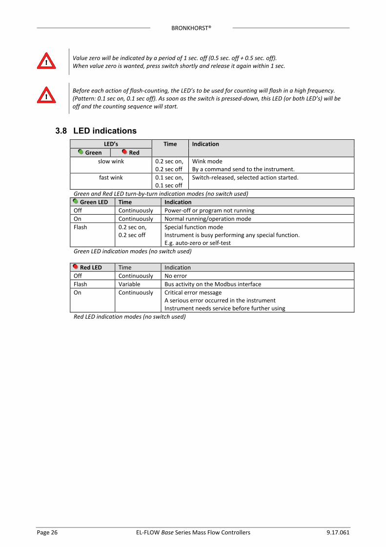
3.8 IED indications LED’s Time Indication
Green Red slow wink 0.2 sec on,
0.2 sec off Wink mode By a command send to the instrument.
fast wink 0.1 sec on, 0.1 sec off
Switch-released, selected action started.
Green and Red LED turn-by-turn indication modes (no switch used) Green LED Time Indication Off Continuously Power-off or program not running On Continuously Normal running/operation mode Flash 0.2 sec on,
0.2 sec off Special function mode Instrument is busy performing any special function. E.g. auto-zero or self-test
Green LED indication modes (no switch used)
Red LED Time Indication Off Continuously No error Flash Variable Bus activity on the Modbus interface On Continuously Critical error message
A serious error occurred in the instrument Instrument needs service before further using
Red LED indication modes (no switch used)

BRONKHORST®
9.17.061 EL-FLOW Base Series Mass Flow Controllers Page 27
3.9 Basic Parameters and Properties
3.9.1 Introduction Every parameter has its own properties. These properties are given in a table as shown: Type Access Range FlowDDE FlowBus ModBus [type] RW [x]…[y] [FB] [Pro]/[Par] [address]/[index]
Type Unsigned char 1 byte character Unsigned char[x] x byte array (string) Unsigned int 2 byte unsigned integer Float 4 byte floating point
Access R The parameter is read-only RW The parameter can be read and write RW The parameter can only be written when the Init Reset parameter is set to 64. See Chapter
4.1.1, General Product Information for more details.
Range Some parameters only accept values within a certain range: [x] Minimal value of the range. [y] Maximal value of the range.
FlowDDE Parameter number in FlowDDE. Check chapter 3.4, “Basic RS232 Flowbus operation”, for detailed information.
FlowBus Process and parameter number to address parameters using the FlowBus protocol. [Pro] Flowbus process number [Par] Flowbus parameter number Check document 9.17.027 , “RS232 interface with FLOW-BUS protocol”, for detailed information.
ModBus PDU Address and register number to address parameters using the ModBus protocol. [address] Hexadecimal PDU address . [index] Decimal register number. For the ModBus protocol every 2 bytes are addressed separately. Check chapter 3.5, “Modbus RS485 operation” for more details.
BRONKHORST®
Page 28 EL-FLOW Base Series Mass Flow Controllers 9.17.061
3.9.2 Basic Parameters
Measured Value (Measure) Type Access Range FlowDDE FlowBus ModBus Unsigned int R 0…41942 8 1/0 0x0020/33
The measured value indicates the amount of mass flow metered by the instrument. The signal of 0...100% will be presented in a range of 0...32000. The maximum signal to be expected is 131.07 %, which is: 41942.
Setpoint Type Access Range FlowDDE FlowBus ModBus Unsigned int RW 0…41942 9 1/1 0x0021/34
Setpoint is used to set the wanted amount of mass flow. Signals are in the same range as the measured value, only setpoint is limited between 0 and 100 %.
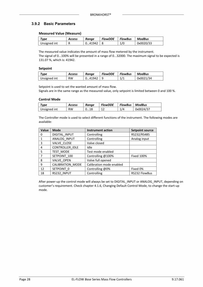
Control Mode Type Access Range FlowDDE FlowBus ModBus Unsigned int RW 0…18 12 1/4 0x0024/37
The Controller mode is used to select different functions of the instrument. The following modes are available:
Value Mode Instrument action Setpoint source 0 DIGITAL_INPUT Controlling RS232/RS485 1 ANALOG_INPUT Controlling Analog input 3 VALVE_CLOSE Valve closed 4 CONTROLLER_IDLE Idle 5 TEST_MODE Test mode enabled 7 SETPOINT_100 Controlling @100% Fixed 100% 8 VALVE_OPEN Valve full opened 9 CALIBRATION_MODE Calibration mode enabled 12 SETPOINT_0 Controlling @0% Fixed 0% 18 RS232_INPUT Controlling RS232 FlowBus
After power-up the control mode will always be set to DIGITAL_INPUT or ANALOG_INPUT, depending on customer’s requirement. Check chapter 4.1.6, Changing Default Control Mode, to change the start-up mode.
BRONKHORST®
9.17.061 EL-FLOW Base Series Mass Flow Controllers Page 29
4 Advanced Operation
4.1 Reading and Changing Instrument Parameters
4.1.1 Introduction
!
All parameters described in this chapter have influence on the behaviour of the mass-flow meter. Please be aware that wrong settings can disorder the output and control response. To avoid un careless changes of these parameters, these parameters are locked. To un-lock these parameters use set parameter “Init Reset” to “UN-LOCKED”
Init Reset Type Access Range FlowDDE FlowBus ModBus Unsigned char RW 82/64 7 0/10 0x000A/11
The Init Reset parameter is used to ‘Un-Lock’ advanced parameters for writing. This parameter knows the following values:
Value Mode Instrument action 82 LOCKED Advanced parameters are
read-only 64 UN_LOCKED Advanced parameters are
write- en readable. This parameter is always set to “LOCKED” at power-up.
4.1.2 Identification
Serial number Type Access Range FlowDDE FlowBus ModBus Unsigned char[20] R - 92 113/3 0xF118..0xF11F/61721..61728
This parameter consists of a maximum 20-byte string with instrument serial number for identification. Example: “M0202123A”
BHT Model number Type Access Range FlowDDE FlowBus ModBus PDU Unsigned char[14] R - 91 113/2 0xF111..0xF117/61713..61719
Bronkhorst® instrument model number information string.
Firmware version Type Access Range FlowDDE FlowBus ModBus PDU Unsigned char[5] R - 105 113/5 0xF128..0XF12A/61737..61739
Revision number of firmware. Eg. “V1.12”
Usertag Type Access Range FlowDDE FlowBus ModBus PDU Unsigned char[13] RW - 115 113/6 0xF130..0xF136/61745..61751
User definable alias string. Maximum 13 characters allow the user to give the instrument his own tag name.
BRONKHORST®
Page 30 EL-FLOW Base Series Mass Flow Controllers 9.17.061
Customer model Type Access Range FlowDDE FlowBus ModBus PDU Unsigned char[16] RW - 93 113/4 0xF120..0xF127/61729..61736
Digital instrument manufacturing configuration information string. This string can be used by Bronkhorst® to add extra information to the model number information.
4.1.3 Fluid Information Next parameters give information about the fluid range of the instrument.
Fluid name Type Access Range FlowDDE FlowBus ModBus PDU Unsigned char[10] RW - 25 1/17 0x8188..0x818C/33161..33165
Fluid name consists of the name of the fluid. Up to 10 characters are available for storage of this name.
Fluid unit Type Access Range FlowDDE FlowBus ModBus PDU Unsigned char[7] R - 129 1/31 0x81F8..0x81FB/33273..33276
The Fluid unit can be read by parameter ‘capacity unit’. This parameter contains the unit in maximal 7 characters.
Fluid Capacity (@100%) Type Access Range FlowDDE FlowBus ModBus PDU Float R ±1E-10… ±1E+10 21 1/13 0x8168..0x8169/33129..33130
Capacity is the maximum value (span) at 100% for direct reading in sensor base units.
Fluid Capacity (@0%) Type Access Range FlowDDE FlowBus ModBus PDU Float R ±1E-10… ±1E+10 183 33/22 0xA1B0..0xA1B1/41393..41394
This is the capacity zero point (offset) for direct reading in sensor base units.
4.1.4 Auto Zeroing To start the auto zero-procedure two parameters should be written:
Control Mode Type Access Range FlowDDE FlowBus ModBus Unsigned int RW 0…18 12 1/4 0x0024/37
Check chapter 3.9.2, “Basic Parameters”, for available control modes.
Calibration Mode Type Access Range FlowDDE FlowBus ModBus Unsigned int RW 9 58 115/1 0x0E61/3682
Value Mode Instrument action 0 IDLE Idle 9 AUTO_ZERO Auto-zeroing 255 ERROR Idle
Procedure: Step 1: Set Control Mode to CALIBRATION_MODE (9) Step 2: Set Calibration Mode to AUTO_ZERO(9) Step 3: Check Calibration Mode,
IDLE Auto-zeroing succeeded AUTO_ZERO Auto-zeroing active ERROR Auto-zeroing failed
BRONKHORST®
9.17.061 EL-FLOW Base Series Mass Flow Controllers Page 31
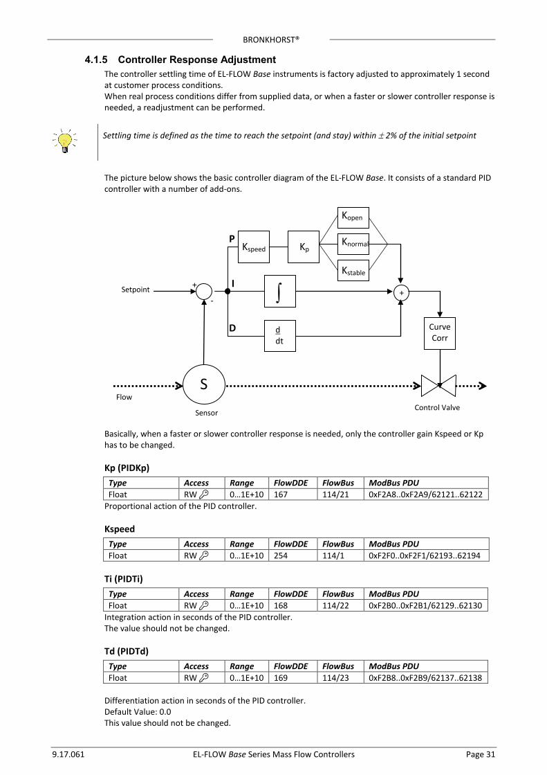
4.1.5 Controller Response Adjustment The controller settling time of EL-FLOW Base instruments is factory adjusted to approximately 1 second at customer process conditions. When real process conditions differ from supplied data, or when a faster or slower controller response is needed, a readjustment can be performed.
Settling time is defined as the time to reach the setpoint (and stay) within ± 2% of the initial setpoint
The picture below shows the basic controller diagram of the EL-FLOW Base. It consists of a standard PID controller with a number of add-ons.
Basically, when a faster or slower controller response is needed, only the controller gain Kspeed or Kp has to be changed.
Kp (PIDKp) Type Access Range FlowDDE FlowBus ModBus PDU Float RW 0…1E+10 167 114/21 0xF2A8..0xF2A9/62121..62122
Proportional action of the PID controller.
Kspeed Type Access Range FlowDDE FlowBus ModBus PDU Float RW 0…1E+10 254 114/1 0xF2F0..0xF2F1/62193..62194
Ti (PIDTi) Type Access Range FlowDDE FlowBus ModBus PDU Float RW 0…1E+10 168 114/22 0xF2B0..0xF2B1/62129..62130
Integration action in seconds of the PID controller. The value should not be changed.
Td (PIDTd) Type Access Range FlowDDE FlowBus ModBus PDU Float RW 0…1E+10 169 114/23 0xF2B8..0xF2B9/62137..62138
Differentiation action in seconds of the PID controller. Default Value: 0.0 This value should not be changed.
∫ d dt
+
Kspeed
S
+
-
Curve Corr
Sensor Control Valve
Flow
Setpoint
Kp
Kopen
Knormal
Kstable
P
I
D
BRONKHORST®
Page 32 EL-FLOW Base Series Mass Flow Controllers 9.17.061
Kopen (RespOpen0) Type Access Range FlowDDE FlowBus ModBus PDU Unsigned char RW 0…255 165 114/18 0x0E52/3667
Controller response when starting-up from 0% (when valve opens). Value 128 is default and means: no correction. Otherwise controller speed will be adjusted as follows: (128-RespOpen0) New response = old response * 1.05
Knormal (ContrResp) Type Access Range FlowDDE FlowBus ModBus PDU Unsigned char RW 0…255 72 114/5 0x0E45/3654
Controller response during normal control (at setpoint step) Value 128 is default and means: no correction. Otherwise controller speed will be adjusted as follows:
05.1)128(__ contrespoldresponsenewresponse −
⋅=
Kstable (RespStable) Type Access Range FlowDDE FlowBus ModBus PDU Unsigned char RW 0…255 141 114/17 0x0E51/3666
Controller response when controller is stable (within band of 2% of setpoint) Value 128 is default and means: no correction. Otherwise controller speed will be adjusted as follows:
05.1)128(__ respstableoldresponsenewresponse −
⋅=
4.1.6 Changing Default Control Mode Instruments are delivered with either analog or digital signal as default setpoint, depending on customer’s requirement. After every (power on) reset the instrument will return to its default control mode. The default control mode can be changed with the following parameter:
IOStatus Type Access Range FlowDDE FlowBus ModBus PDU Unsigned char RW 0…255 86 114/11 0xF258/62041
Bit 6 [7..0] represents the former analog jumper. 1 = default control mode is analog 0 = default control mode is digital Procedure for changing default digital operation to default analog operation: • Read IOStatus • Add 64 to the read value ])400[( xOR • Write IOstatus Procedure for changing default analog operation to default digital operation: • Read IOStatus
BRONKHORST®
9.17.061 EL-FLOW Base Series Mass Flow Controllers Page 33
• Subtract 64 from the read value ])400[( xAND • Write IOstatus
4.1.7 Display Filter The output signal of an EL-FLOW Base instrument (measured value) is filtered. The filter has dynamic behaviour: when a change in sensor signal is detected, the measured value will be less filtered than when the sensor signal is constant and stable. There are two filter constants: Static Display Factor and Dynamic Display Factor. These two factors can be transformed into time constants using the following formula:
factorfactorcycletime −
⋅=1t
The measured value is filtered with a first order low pass filter with a filter time constant between these two τ values.
Dynamic Display Factor Type Access Range FlowDDE FlowBus ModBus PDU Float RW 0 … 1.0 56 117/1 0xF508..0xF509/62729..62730
Static Display Factor
Type Access Range FlowDDE FlowBus ModBus PDU Float RW 0 … 1.0 57 117/2 0xF511..0xF512/62737..62738
CycleTime
Type Access Range FlowDDE FlowBus ModBus PDU Unsigned char R 0…255 52 114/12 0x0E4C/3661
Note: The unit of parameter CycleTime is 10ms. Example: value 0.2 means 2ms
4.1.8 Disabling Micro Switch It is possible to disable the Micro Switch on top of the instrument. This can prevent undesired use of this button. Disabling the micro switch can be performed with the following parameter:
IOStatus Type Access Range FlowDDE FlowBus ModBus PDU Unsigned char RW
0…255 86 114/11 0xF258/62041
Bit 3 [7..0] is used to disable the micro switch. 0 = micro switch disabled 1 = micro switch enabled Procedure to enable the micro switch: • Read IOStatus • Add 8 to the read value • Write IOstatus Procedure to disable the micro switch: • Read IOStatus • Subtract 8 from the read value • Write IOstatus
BRONKHORST®
Page 34 EL-FLOW Base Series Mass Flow Controllers 9.17.061
4.2 Using other gasses than specified Each instrument has been calibrated and adjusted for customer process conditions. Controllers or valves may not operate correctly, if process conditions vary too much, because of the restriction of the orifice in the valve. For flowmeters performance and accuracy may be affected tremendously if physical fluid properties such as heat capacity and viscosity change due to changing process conditions. Check chapter 1.7, “Operating Principles”, for detailed information about the sensor principle.
4.2.1 Software for conversion factor calculation Bronkhorst® gathered the physical properties of over 600 fluids in a database called FLUIDAT. Application software, such as FLOW CALCULATIONS, enables the user to calculate accurate conversion factors, not only at 20°C/1 atm but at any temperature/pressure combination, both for gases and for liquids. Apply to your distributor for more details of this software.
Check FLUIDAT® on http://www.fluidat.com FLUIDAT® is a collection of routines to calculate physical properties of gases and liquids. These routines are made available at the FLUIDAT® on the Net website.
4.2.2 Maximum pressure drop For (pilot) solenoid operated control valves with small orifices the maximum allowable pressure drop for gases is according to the table.
Diameter [mm] Kv Normally closed ∆p max. [bard]
Normally opened ∆p max. [bard]
0,05 0,07 0,10 0,14 0,20 0,30 0,37 0,50 0,70 1,00 1,30 1,50 1,70 2,00 4,50
4,33 x 10⁻⁵ 8,48 x 10⁻⁵ 1,73 x 10⁻⁴ 3,39 x 10⁻⁴ 6,93 x 10⁻⁴ 1,56 x 10⁻³ 2,37 x 10⁻³ 4,33 x 10⁻³ 8,48 x 10⁻³ 1,73 x 10⁻² 2,93 x 10⁻² 3,90 x 10⁻² 5,00 x 10⁻² 6,63 x 10⁻²
3,50 x 10⁻¹
40 30 30 30 30 30 30 30 24 12 8 6 5 3,6 5
30 20 20 20 20 20 20 20 15 8 5 n.a. n.a. n.a n.a..
For pilot operated valves the maximum pressure drop is limited to 20 bard. If the pressure drop during start-up is higher, it is preferred to install a bypass valve. During start-up this valve should be opened. Also the minimum pressure drop is limited. For exact figures consult factory or proceed according to the technical data and/or additional instructions given by the sales office or department.
BRONKHORST®
9.17.061 EL-FLOW Base Series Mass Flow Controllers Page 35
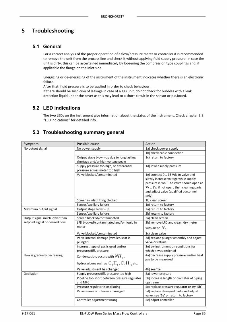
5 Troubleshooting
5.1 General For a correct analysis of the proper operation of a flow/pressure meter or controller it is recommended to remove the unit from the process line and check it without applying fluid supply pressure. In case the unit is dirty, this can be ascertained immediately by loosening the compression type couplings and, if applicable the flange on the inlet side. Energizing or de-energizing of the instrument of the instrument indicates whether there is an electronic failure. After that, fluid pressure is to be applied in order to check behaviour. If there should be suspicion of leakage in case of a gas unit, do not check for bubbles with a leak detection liquid under the cover as this may lead to a short-circuit in the sensor or p.c.board.
5.2 IED indications The two LEDs on the instrument give information about the status of the instrument. Check chapter 3.8, “LED indications” for detailed info.
5.3 Troubleshooting summary general
Symptom Possible cause Action No output signal No power supply 1a) check power supply
1b) check cable connection Output stage blown-up due to long lasting shortage and/or high-voltage peaks
1c) return to factory
Supply pressure too high, or differential pressure across meter too high
1d) lower supply pressure
Valve blocked/contaminated 1e) connect 0 .. 15 Vdc to valve and slowly increase voltage while supply pressure is ‘on’. The valve should open at 7V ± 3V; if not open, then cleaning parts and adjust valve (qualified personnel only)
Screen in inlet fitting blocked 1f) clean screen Sensor/capillary failure 1g) return to factory
Maximum output signal Output stage blown-up 2a) return to factory Sensor/capillary failure 2b) return to factory
Output signal much lower than setpoint signal or desired flow
Screen blocked/contaminated 3a) clean screen LFD blocked/contaminated and/or liquid in meter
3b) remove LFD and clean; dry meter
with air or 2N
Valve blocked/contaminated 3c) clean valve Valve internal damage (swollen seat in plunger)
3d) replace plunger assembly and adjust valve or return
Incorrect type of gas is used and/or pressure/diff. pressure
3e) try instrument on conditions for which it was designed
Flow is gradually decreasing Condensation, occurs with 3NH ,
hydrocarbons such as 10483 HC,HC etc.
4a) decrease supply pressure and/or heat gas to be measured
Valve adjustment has changed 4b) see ‘1e’ Oscillation Supply pressure/diff. pressure too high 5a) lower pressure
Pipeline too short between pressure regulator and MFC
5b) increase length or diameter of piping upstream
Pressure regulator is oscillating 5c) replace pressure regulator or try ‘5b’ Valve sleeve or internals damaged 5d) replace damaged parts and adjust
valve, see ‘1e’ or return to factory Controller adjustment wrong
5e) adjust controller

BRONKHORST®
Page 36 EL-FLOW Base Series Mass Flow Controllers 9.17.061
Symptom Possible cause Action Small flow at zero setpoint Valve leaks due to damaged plunger or dirt in
orifice 6a) clean orifice and/or, when replacing plunger assembly, see ‘1e’
Pressure too high or much too low 6b) apply correct pressure High flow at zero setpoint Damaged diaphragm (only applicable to
valves with membrane) 7a) replace membrane seal
BRONKHORST®
9.17.061 EL-FLOW Base Series Mass Flow Controllers Page 37
6 Removal and Return Instructions Instrument handlings: • Purge gas lines • Remove instrument from line • Insert the instrument into a plastic bag and seal the bag • Place the bag in a appropriate shipping container Add documentation: • Reason of return • Failure symptoms • Contaminated condition • Declaration on Contamination form: 9.17.032 When returning material, always describe the problem and if possible the work to be done, in a covering letter. It is absolutely required to notify the factory if toxic or dangerous fluids have been metered with the instrument! This to enable the factory to take sufficient precautionary measures to safeguard the staff in their repair department. Take proper care of packing, if possible use the original packing box; seal instrument in plastic etc. All instruments must be dispatched with a completely filled in 'declaration on contamination form'. Instruments without this declaration will not be accepted. Note: If the instruments have been used with toxic or dangerous fluids the customer should pre-clean the instrument. Important: Clearly note, on top of the package, the customer clearance number of Bronkhorst High-Tech B.V., namely:
NL801989978B01 If applicable, otherwise contact your distributor for local arrangements.
The declaration on contamination form is available at the Bronkhorst download site: http://www.bronkhorst.com/en/downloads/
BRONKHORST®
Page 38 EL-FLOW Base Series Mass Flow Controllers 9.17.061
7 Service For current information on Bronkhorst® and service addresses please visit our website:
http://www.bronkhorst.com
Do you have any questions about our products? Our Sales Department will gladly assist you selecting the right product for your application. Contact sales by e-mail:
For after-sales questions, our Customer Service Department is available with help and guidance. To contact CSD by e-mail:
No matter the time zone, our experts within the Support Group are available to answer your request immediately or ensure appropriate further action. Our experts can be reached at:
+31 859 02 18 66