911 Turbo - files.porsche.com
262
911 Turbo Driver’s Manual
Transcript of 911 Turbo - files.porsche.com

911 TurboDriver’s Manual
10_Turbo_20.book Seite 1 Freitag, 7. August 2009 12:55 12

Porsche, the Porsche Crest, 911, PCCB, PCM, PDK, PSM and Tequipment are registered trademarks of Dr. Ing. h.c. F. F. Porsche AG.
Printed in Germany.
Reprinting, even of excerpts, or duplication of any type is only permissible with the written authorisation of Dr. Ing. h.c. F. Porsche AG.
© Dr. Ing. h.c. F. Porsche AGPorscheplatz 1D-70435 Stuttgart
Suggestions
Do you have any questions, suggestions or ideas for your vehicle or for the on-board literature? Please write to us:
Dr. Ing. h.c. F. Porsche AGVertrieb Customer RelationsPorschestrasse 15-1971634 Ludwigsburg
On-board literature
f Please always keep this literature in the vehicle and please hand it over to the new owner if you sell your vehicle.
WKD 997 220 10 6/09
10_Turbo_20.book Seite 2 Freitag, 7. August 2009 12:55 12

1
Orientation guides in the Driver’s Manual
The orientation guides in the Driver’s Manual are highlighted in yellow in each case.
Overall table of contents
At the start of the Driver’s Manual you will find an overview of the overall contents of the Driver’s Manual.
Section contents
There is a summary of topics with the corresponding page numbers at the beginning of each main chapter.
Index
There is a detailed, alphabetical index at the end of this Driver’s Manual.
Equipment
Because our vehicles undergo continuous development, equipment and specification may not be as illustrated or described in this Driver’s Manual.
Items of equipment are sometimes optional or vary depending on legal requirements or on the country in which the vehicle is sold. Your Porsche partner will be pleased to advise you on retrofitting such equipment.
Should your Porsche be fitted with any equipment not described in this Manual, your Porsche partner will be glad to provide information concerning correct operation and care of the items concerned.
Because of different legal requirements in individual countries, the equipment in your vehicle may vary slightly from that described in this Driver’s Manual.
Technical modifications
Modifications may be carried out on your vehicle only if approved by Porsche.This ensures that your Porsche will remain reliable and safe to drive, and that it will not be damaged as a result of the modifications.Your Porsche partner will be pleased to advise you.
d Safety notes!
f Only use genuine Porsche spare parts for your vehicle or spare parts of similar quality which have been manufactured according to the specifications and production requirements of Porsche. These parts are available from your Porsche partner or a qualified specialist workshop. Accessories which are relevant to safety should not be used unless they have been obtained from the Porsche Tequipment product range or have been tested and approved by Porsche. Your Porsche partner will be pleased to advise you and answer any
of your questions. However, the use of other parts or accessories may adversely affect the safety of your vehicle, and Porsche can take no responsibility for any loss or damage caused by their use.Even if the supplier of other accessories or parts is a recognised supplier, the safety of your vehicle may still be affected if such items are installed. Due to the large variety of products offered in the accessory market, it is not possible for Porsche to inspect and approve every one.
f In addition, please note that the use of replacement parts which are not genuine Porsche parts or approved parts or the use of accessories not approved by Porsche may also detrimentally affect the Warranties relating to your vehicle.
f Regularly check your vehicle for signs of damage.Damaged or missing aerodynamic components such as spoilers or underside panels affect driving behaviour and must therefore be replaced immediately.
10_Turbo_20.book Seite 1 Freitag, 7. August 2009 12:55 12

2
Setting and operating vehicle components when driving
d Warning!
Operating the on-board computer, radio, navigation system, telephone or other equipment while driving is dangerous and can result in an accident.This could distract you from the traffic and cause you to lose control of the vehicle.
f Operate these components while driving only if the traffic situation allows you to do so safely.
f Carry out any complicated operating or setting procedures only while the vehicle is stationary.
Porsche Ceramic Composite Brake (PCCB)
The high-performance brake system is designed for optimal braking effect at all speeds and temperatures. Certain speeds, braking forces and ambient conditions (such as temperature and humidity) may therefore cause the brakes to squeal.
Wear on different components of the brake system, e.g. brake pads or brake discs, depends to a great extent on the individual driving style and the conditions of use and therefore cannot be expressed in actual miles on the road.
The values communicated by Porsche are based on normal operation adapted to traffic. Wear increases considerably when the vehicle is driven on race tracks or through an aggressive driving style.
f Before using your vehicle in this way, please consult your Porsche partner about the guidelines which currently apply.
Ground clearance
d Caution!
Risk of damage.The vehicle may touch the ground as a result of the small ground clearance.
f Drive carefully and slowly on steep slopes (e.g. in multi-storey car parks), kerbs, uneven roads, platform lifts, etc.
f Avoid steep ramps.
f When towing and when recovering with a towing vehicle, pay attention to the small ground clearance.
Sports tyres
Sports tyres (ultra high performance tyres) are approved for use on public highways and comply with all statutory requirements and safety criteria.The design of the tyre is also geared towards use on race circuits (driver safety training courses,
sports driving schools, Club Sport events) and provides distinct advantages here in terms of dry grip and wear compared with conventional road tyres.
The major features are a reduced tread depth, as well as a special tread pattern and carcass.
The design features of these sports tyres result in the following effects compared with other summer tyres when used under normal driving conditions:
– Due to the lower tread depth, sports tyres can reach their wear limit earlier.As for all tyres, the possible driven distance depends on the individual driving style and service conditions.
– On wet roads, in particular in aquaplaning situations (stagnant water, puddles, lane grooves…), it is advisable to exercise caution because of the lower tread depth and to adapt speed accordingly (as is generally the case for normal road tyres and with reduced tyre tread depths).
– The higher performance at the performance limits requires that attention be adapted to suit, because any infringement of an upper performance limit also harbours greater risks.
– Change to winter tyres when external temperatures drop below 7 °C.
10_Turbo_20.book Seite 2 Freitag, 7. August 2009 12:55 12

3
f Notify anyone using your car of these characteristics and possible effects.
d Danger!
Risk of accident through loss of road surface contact, control over the vehicle and braking ability. The reduced tyre tread depth means that there is an increased risk of aquaplaning on wet roads.
f When driving on wet or mud-covered roads reduce speed significantly.
d Danger!
Risk of accident.Due to the lower tread depth, sports tyres can reach their wear limit earlier.
f Regularly check the tread depth.
Driving on race circuit (e.g. sports driving schools, Club Sport events)
Brake fluid, brake pads and brake discs
Brake fluid absorbs moisture from the air over time. This accumulation of water lowers the boiling point and can impair braking action at higher temperature loads such as when driving on race circuits (Sports driving schools, Club Sport events).
For this reason, brake fluid should not be more than 12 months old when driving on race circuits (Sports driving schools, Club Sport events).
f Please refer to the “Guarantee & Maintenance” booklet.
Wear on the brake pads and brake discs is extremely dependent on the individual driving style and service conditions. At higher temperature loads such as when driving on race circuits (Sports driving schools, Club Sport events), wear on the brake components is significantly increased.
f Therefore, before driving on race circuits (Sports driving schools, Club Sport events) the brake pads and brake discs should always be inspected first for signs of wear.
Racing tyres
f Please observe the chapter “SPORTS TYRES” on Page 2.
The fitting of racing tyres (e.g. slicks) for sporting events is not approved by Porsche.Very high cornering speeds can be achieved with racing tyres. The resulting lateral acceleration values would jeopardise the adequate supply of oil to the engine.Porsche therefore refuses to accept any guarantee or liability for damage occurring as a result of non-compliance with this provision.
Tailpipes
d Warning!
Danger of burns near tailpipes or in the event of contact with tailpipes. Tailpipes are hot when the engine is running and for some time after the engine is switched off.
f Keep a safe distance away from the tailpipes when you are behind the vehicle.
f Make sure that children do not burn themselves on the tailpipes.
Recycling
In European Union countries only:Returning end-of-life vehicles
Porsche AG will arrange for your old Porsche to be recycled in an environmentally compatible manner, free of charge.To return your vehicle and obtain the relevant Certificate of Destruction, please consult your Porsche dealer, who will gladly assist you in disposing of your old vehicle.
10_Turbo_20.book Seite 3 Freitag, 7. August 2009 12:55 12

4 Contents
Contents
Before Driving Off ................................ 6Before driving off ............................................6Tips for Running In ..........................................6Overview Illustrations ......................................7
Controls, Safety................................... 9Keys ............................................................10Key with Radio Remote Control ......................11Central Locking ............................................13Doors ..........................................................16Door oddments tray......................................16Theft protection............................................16Alarm System,Passenger Compartment Monitoring System ........................................................17Power windows.............................................18Door Mirrors.................................................20Automatic Anti-Dazzle Interior and Door Mirrors ..........................................21Heated Rear Window/Door Mirror Heating ......22Seat Adjustment ...........................................23Seat Memory................................................26Seat Heating ................................................28Seat ventilation .............................................29Rear Seat Backrests .....................................30Steering wheel adjustment.............................30Steering Wheel Heating .................................31Multi-Functional Steering Wheel ......................32Sun Visors....................................................33Seat belts ....................................................34
Child Restraint System ..................................36Airbag systems.............................................40Roll-over protection .......................................42Handbrake....................................................43Footbrake.....................................................44ABS Brake System........................................46Sport mode ..................................................47Porsche Stability Management (PSM)..............49Porsche Active Suspension Management (PASM) .........................................................52Porsche Traction Management (PTM)..............52Porsche Torque Vectoring (PTV).....................53Dynamic Engine Mounting (PADM) ..................53Retractable Rear Spoiler................................54Interior lights ................................................56Parking Aids .................................................57Ignition Lock/Steering Lock ...........................59Starting and Stopping the Engine ...................61Light switch ..................................................63Home mode .................................................63Headlight beam adjustment............................64Direction Indicator/High Beam/Parking Light/Headlight Flasher Stalk .............64Individual Light Functions ...............................64Windscreen Wiper/Washer Stalk.....................65Cruise Control ..............................................68Hazard Warning Lights ..................................70Cupholder ....................................................70Ashtray ........................................................72Cigarette Lighter...........................................72Storage........................................................73
Luggage compartment lid and engine compartment lid........................................... 75Luggage Compartment................................. 76Car Telephones and Two-Way Radios............. 77Rod Antenna ................................................ 77Porsche Communication Management (PCM) .......................................................... 78iPod, USB and AUX....................................... 78Fire Extinguisher .......................................... 79HomeLink .................................................... 80
Automatic Air-Conditioning System, Heated Rear Window/Door Mirror Heating........................... 83Automatic Air-Conditioning System................. 84Central and Side Vents ................................ 87Heated Rear Window/Door Mirror Heating...... 88
Instruments, On-Board Computer, Warning Messages ............................ 89Instrument Panel .......................................... 90Engine Oil Temperature ................................ 92Cruise Control Indicator Light ....................... 92Instrument Illumination .................................. 92Trip Counter ................................................ 93Speedometer............................................... 94Changing Over Between Kilometres/Miles ...... 94Gear Shift Indicator “A”(in vehicles with manual transmission) ............ 94Tachometer ................................................. 95
10_Turbo_20.book Seite 4 Freitag, 7. August 2009 12:55 12

Contents 5
Direction Indicator.........................................95High Beam ...................................................95Cooling System ............................................95Porsche Doppelkupplung Transmission (PDK) ...........................................................97Fuel .............................................................98Clock ...........................................................99Outside Temperature ....................................99Engine Oil Pressure.....................................100Battery/Generator.......................................100Central Warning Light ..................................101Brake Warning Light....................................101Check Engine (Emission control) ..................101On-Board Computer ....................................102Warning Messages......................................134
Shifting Gears.................................. 143Manual Transmission, Clutch........................144Drive-Off Assistant ......................................145Porsche Doppelkupplung Transmission (PDK) .........................................................146
Mobile Roofs ................................... 153Sliding/Lifting roof ......................................154Convertible Top ..........................................158Windstop....................................................168Hardtop .....................................................172Roof Transport System ...............................178
Maintenance, Care .......................... 179Notes on Maintenance.................................180Coolant Level..............................................181Engine Oil Level ..........................................182Brake Fluid Level.........................................184Fuel ...........................................................186Fuel Can.....................................................187Emission Control System.............................188Washer Fluid...............................................189Power Steering ...........................................190Air cleaner..................................................191Combination filter........................................191Wiper Blades ..............................................191Car Care Instructions ..................................192
Practical Tips, Minor Repairs .......... 199Notes on Minor Repairs ...............................200Tyres and Wheels........................................201Wheel Bolts ................................................206Changing a Wheel .......................................207Changing a Central Locking Wheel................209Flat Tyre.....................................................215Electrical System ........................................219Battery.......................................................223Jump Lead Starting .....................................228Bulb chart ..................................................229Replacing Bulbs ..........................................229Headlights ..................................................230
Number Plate Light..................................... 238Changing Light-Emitting Diodes and Long-Life Bulbs .................................... 238Changing headlights from left to right-hand traffic..................................... 239Headlight adjustment.................................. 240Towing and Tow-Starting............................. 241
Vehicle Identification, Technical Data ................................ 243Vehicle Identification Data ........................... 244Technical Data ........................................... 246
Index .............................................. 252
10_Turbo_20.book Seite 5 Freitag, 7. August 2009 12:55 12

6 Before Driving Off
Before driving offf Check the filling pressure, tread and condition
of all tyres.
f Clean headlight lenses, rear lights, direction indicators and windows.
f Check operation of headlights, brake lights and direction indicators with the ignition switched on.
f Check operation of warning lights and indicator lights with ignition switched on and engine switched off.
f Ensure that fuel supply is adequate.
f Adjust interior and exterior mirrors for proper vision to the rear.
f Fasten seat belts – driver and passengers.
f Check all fluid levels regularly, even between service intervals.
Tips for Running InThe following tips will be helpful in obtaining optimum performance from your new Porsche.
Despite the most modern, high-precision manufacturing methods, the “wearing in” of moving parts with each other cannot be completely avoided. This wearing in occurs mainly in the first 3,000 km (1,865 miles).
During the first 3,000 km (1,865 miles) you should:
f Preferably take longer trips.
f Avoid frequent cold starts with short-distance driving whenever possible.
f Not participate in motor racing events, sports driving schools or similar.
f Avoid high engine speeds, especially when the engine is cold.
Oil and fuel consumption
The oil and fuel consumption may be somewhat higher than normal during the running-in period.
f Please observe the chapter “TECHNICAL DATA” on Page 246.
Bedding in new brake pads and brake discs
New brake pads and brake discs have to be “bedded in”, and therefore only attain optimal friction when the vehicle has covered several hundred km or miles. The slightly reduced braking ability must be compensated for by pressing the brake pedal harder. This also applies whenever the brake pads or brake discs are replaced.
Running in new tyres
f Note: New tyres do not have their full road-holding ability at first.The new tyres should therefore be broken in by driving at moderate speeds for the first 100–200 km (60–120 miles).
10_Turbo_20.book Seite 6 Freitag, 7. August 2009 12:55 12

Before Driving Off 7
1 Door handle
2 Power windows
3 Door mirror adjuster
4 Hands-free microphone
5 Switch for seat memory
6 Diagnostic socket
7 Lid release
8 Steering wheel adjustment
9 Seat height, fore-and-aft and angle adjustment
10 Backrest adjustment
11 Lumbar support adjustment
12 Heated steering wheel
10_Turbo_20.book Seite 7 Freitag, 7. August 2009 12:55 12

8 Before Driving Off
1 Light switch
2 Ignition lock/steering lock
3 Direction indicator, dipped beam and headlight flasher stalk
4 Operating lever for on-board computer
5 Horn
6 Operating lever for cruise control
7 Control stalk for wiper/washer, rear window wiper
8 Stopwatch
9 Interior temperature sensor
10 Button for hazard warning lights
11 Central locking button
12 Cupholder
13 Seat heating/seat ventilation, left
14 Operating panel for air conditioning
15 Button for Sport programme, Sport Plus programmePorsche Active Suspension Management (PASM)Rear spoilerPorsche Stability Management (PSM)
16 Seat heating/seat ventilation, right
17 Control panel for Porsche Communication Management (PCM), see separate operating instructions
10_Turbo_20.book Seite 8 Freitag, 7. August 2009 12:55 12

Controls, Safety 9
Controls, SafetyKeys ............................................................10Key with Radio Remote Control ......................11Central Locking ............................................13Doors ..........................................................16Door oddments tray......................................16Theft protection............................................16Alarm System,Passenger Compartment Monitoring System ........................................................17Power windows.............................................18Door Mirrors.................................................20Automatic Anti-Dazzle Interior and Door Mirrors ..........................................21Heated Rear Window/Door Mirror Heating ......22Seat Adjustment ...........................................23Seat Memory................................................26Seat Heating ................................................28Seat ventilation .............................................29Rear Seat Backrests .....................................30Steering wheel adjustment.............................30Steering Wheel Heating .................................31Multi-Functional Steering Wheel ......................32Sun Visors....................................................33Seat belts ....................................................34Child Restraint System ..................................36Airbag systems.............................................40Roll-over protection .......................................42Handbrake ...................................................43Footbrake ....................................................44
ABS Brake System........................................46Sport mode..................................................47Porsche Stability Management (PSM)..............49Porsche Active Suspension Management (PASM).........................................................52Porsche Traction Management (PTM) .............52Porsche Torque Vectoring (PTV).....................53Dynamic Engine Mounting (PADM) ..................53Retractable Rear Spoiler................................54Interior lights ................................................56Parking Aids .................................................57Ignition Lock/Steering Lock ...........................59Starting and Stopping the Engine ...................61Light switch..................................................63Home mode .................................................63Headlight beam adjustment ...........................64Direction Indicator/High Beam/Parking Light/Headlight Flasher Stalk .............64Individual Light Functions ...............................64Windscreen Wiper/Washer Stalk.....................65Cruise Control ..............................................68Hazard Warning Lights ..................................70Cupholder ....................................................70Ashtray ........................................................72Cigarette Lighter...........................................72Storage........................................................73Luggage compartment lid and engine compartment lid ...........................................75Luggage Compartment .................................76
Car Telephones and Two-Way Radios..............77Rod Antenna.................................................77Porsche Communication Management (PCM)...........................................................78iPod, USB and AUX .......................................78Fire Extinguisher ...........................................79HomeLink.....................................................80
10_Turbo_20.book Seite 9 Freitag, 7. August 2009 12:55 12

10 Controls, Safety
KeysYou will receive two vehicle keys with which you can operate all the locks on your vehicle.
f Be careful with your vehicle keys: do not part with them except under exceptional circumstances.
f Inform your insurance company of any loss or theft of vehicle keys or if extra or replacement keys have been made.
f Remove the ignition key, even if leaving the vehicle only briefly.Engage the steering lock correctly.
Emergency operation
f Please observe the chapter “EMERGENCY OPERATION – RELEASING THE IGNITION KEY” on Page 60.
Replacement keys
Car keys can only be ordered from a Porsche partner. Sometimes, this may take a long time.You should therefore always keep a spare key on your person. Keep it in a safe place, but under no circumstances in or on the vehicle.
The key codes of new keys have to be “taught” to the vehicle control unit by your Porsche partner.
Teach-in can be carried out for a total of 6 vehicle keys.
Disabling key codes
If a key is lost, the key codes can be disabled by a Porsche partner.All the remaining car keys are required for this purpose.Disabling the code ensures that the car can be started only using authorised keys.
Note
f Please note that the other locks can still be opened with the disabled key.
Immobiliser
There is a transponder (an electronic component) in the key grip, containing a stored code. When the ignition is switched on, the ignition lock checks the code.The immobiliser can be switched off and the engine started only using an authorised ignition key.
Switching off the immobiliser
f Insert the ignition key into the ignition lock.
If the ignition is left on for more than 2 minutes without the engine being started, the immobiliser is reactivated.
f If this happens, turn the ignition key back to the 3 position (ignition off) before starting the engine. The immobiliser is then deactivated again, and the engine can be started.
Switching on the immobiliser
f Remove ignition key.
Security wheel bolts
f If the wheels have to be removed at the workshop, please do not forget to hand over the socket for the security wheel bolts along with the vehicle key.
10_Turbo_20.book Seite 10 Freitag, 7. August 2009 12:55 12

Controls, Safety 11
1 - Central locking button2 - Button for luggage compartment lid3 - Cabriolet: Button for convertible top4 - Light-emitting diode
Key with Radio Remote Control
Unlocking the vehicle
f Press button 1 briefly.
Locking the vehicle
f Press button 1 briefly.
Switching off the alarm system if it is triggered accidentally
f Press button 1 briefly.
Unlocking luggage compartment lid
f Press button 2 for approx. two seconds.
If the vehicle was locked, it is unlocked simultaneously with the luggage compartment. On vehicles with seat memory, the stored seat and door mirror positions are adjusted automatically.Approx. 80 seconds after closing the luggage compartment, the vehicle is locked again if no other doors are opened.
After relocking, the doors can be opened again with the inner door handle (theft protection is limited).
Note
It is possible to program further unlocking variants for the luggage compartment.
f Consult a qualified specialist workshop. We recommend that you use a Porsche partner for this work since these are staffed with trained personnel and have the necessary parts and tools.
Option 1
The relocking time of the doors can be adjusted to suit your individual requirements: 10–100 seconds.
Option 2
The doors stay locked when the luggage compartment is unlocked.
Operating the convertible top
f Please observe the chapter “CONVERTIBLE TOP” on Page 158.
10_Turbo_20.book Seite 11 Freitag, 7. August 2009 12:55 12

12 Controls, Safety
The remote control standby function switches off after 7 days
If the vehicle is not started or unlocked with the remote control within seven days, the remote control standby function is switched off (to save the vehicle battery).
1. In this case, unlock the driver’s door with the key at the door lock.Leave the door closed in order to prevent the alarm system from being triggered.
2. Press button 1 on the remote control.
The remote control is now activated again.
Operational readiness of the remote control interrupted
Each time the remote control is operated, encrypted data is transmitted to the vehicle. If the radio remote control is operated too often outside the range of the vehicle, this can result in the central locking system no longer reacting. In this case, the remote control and vehicle must be synchronised.
Performing synchronisation
1. Unlock the driver’s door with the car key.
2. Open the driver’s door and insert the ignition key into the ignition lock within 10 seconds to prevent the alarm system from being triggered.
3. With the key inserted, press and hold button 1 on the remote control for approx. 5 seconds. The synchronisation is now complete.
10_Turbo_20.book Seite 12 Freitag, 7. August 2009 12:55 12

Controls, Safety 13
Central Lockingf Please observe the chapter “SEAT MEMORY”
on Page 26.
f Please observe the chapter “LOAD SWITCH-OFF AFTER 2 HOURS OR 7 DAYS” on Page 220.
Both car doors and the filler flap can be centrally unlocked or locked with the remote control.
A short signal from the alarm horn will draw your attention to the fact that the following components are not completely closed when you lock the vehicle:
– Driver’s door (The vehicle cannot be locked if the driver's door is not completely closed.).
– Passenger’s door
– Luggage compartment lid
– Engine compartment lid
– Glove compartment
Note on operation
Further unlocking variants are available in vehicles with the Sport Chrono Turbo package.
f Please observe the chapter “Individual Memory” in the separate PCM operating instructions.
Automatic relocking
If the vehicle is unlocked using the remote control and if none of the doors are opened within approx. 100 seconds, automatic relocking takes place.This relocking time can be adapted to your individual requirements (10–100 seconds).
f Consult a qualified specialist workshop. We recommend that you use a Porsche partner for this work since these are staffed with trained personnel and have the necessary parts and tools.
Note
The doors can be opened after automatic relocking by pulling the inner door handle twice (theft protection is limited).
The desired locking condition can be achieved by unlocking/locking again.
Locking conditions
d Warning!
If the vehicle is only locked once, passengers remaining inside the car cannot open the door in an emergency.
f Quickly press button 1 of the remote control twice so that the door can be opened with the inner door handle.
f Lock vehicle once.The doors cannot be opened, either from outside or from inside. The alarm system and passenger compartment monitoring system are switched on.
f Quickly press button 1 of the remote control twice.The passenger compartment monitoring system is switched off. The doors are locked but can be opened from the inside. To do this:
1. Pull inner door handle once.Door lock is unlocked.
2. Pull inner door handle again.Door can be opened.
f Inform any persons remaining in the vehicle that the alarm system will be triggered if the door is opened.
10_Turbo_20.book Seite 13 Freitag, 7. August 2009 12:55 12

14 Controls, Safety
Malfunction of the remote control
The remote control may not function correctly due to local radio waves. The vehicle will then not lock properly.This can be identified by the missing locking sound and the missing check-back signal of the hazard warning lights.
Emergency operation – opening
f Unlock the driver’s door with the key at the door lock.Open door within 20 seconds and insert the ignition key into the ignition lock within 10 seconds to prevent the alarm system from being triggered.
Note on operation
If the door is not opened within approximately 20 seconds, automatic relocking takes place. The alarm system will be triggered by the next unlocking of the door:
f Insert the ignition key into the ignition lock to switch off the alarm system.
Emergency operation – closing
f Lock the driver’s door with the key at the door lock.If there is a defect in the central locking system, all functioning elements of the central locking system will be locked.The alarm system is switched on; the passenger compartment monitoring system is switched off.
f Consult a qualified specialist workshop. We recommend that you use a Porsche partner for this work since these are staffed with trained personnel and have the necessary parts and tools.
Indication by the hazard warning lights
If the remote control is used for unlocking or locking, feedback is provided by the hazard warning lights:
– Unlocking – single flash
– Locking once – double flash
– Locking twice – continuous illumination for approx. 2 seconds. Passenger compartment monitoring system is switched off.
Fault indication
A double horn signal during locking indicates a fault in the central locking system or alarm system.
f Consult a qualified specialist workshop. We recommend that you use a Porsche partner for this work since these are staffed with trained personnel and have the necessary parts and tools.
10_Turbo_20.book Seite 14 Freitag, 7. August 2009 12:55 12

Controls, Safety 15
Central locking button
The central locking button on the dashboard lets you lock and unlock both doors electrically.If the doors were locked with the key or by the remote control, they cannot be unlocked with the button.
Locking
f Press the central locking button.When the ignition is switched on, the light-emitting diode in the button is lit.The doors can be opened by pulling the inner door handle twice.
Unlocking
f Press the central locking button.Light-emitting diode goes out.
Automatic door locking
Automatic door locking can be programmed in the control unit of the central locking system:Doors lock automatically when a speed of 5–10 km/h (3–6 mph) is exceeded.
f Consult a qualified specialist workshop. We recommend that you use a Porsche partner for this work since these are staffed with trained personnel and have the necessary parts and tools.
On vehicles with the Sport Chrono Turbo package, the PCM can be used to activate automatic door locking.
f Please observe the chapter “Individual Memory” in the separate PCM operating instructions.
Note
Automatically locked doors can be unlocked with the central locking button or opened by pulling on the inner door handle twice.
Overload protection
If the central locking system is operated more than ten times within a minute, further operation is blocked for 30 seconds.
10_Turbo_20.book Seite 15 Freitag, 7. August 2009 12:55 12

16 Controls, Safety
DoorsClosed door windows will be automatically lowered by a few millimetres when the door is opened and raised again when the door is closed. This makes it easier to open and close the doors and protects the seals.
f Therefore, you should pull the door handle slowly so that the door window can be lowered before the door is opened.
Opening doors from outside
f Unlock the doors with the remote control.
f Slowly pull door handle A.
Opening unlocked doors from inside
f Slowly pull door handle B.
Opening locked doors from inside
f Pull door handle B twice.
f Please observe the chapter “LOCKING CONDITIONS” on Page 13.
Door oddments tray
Opening the oddments tray
f Lift up cover C.
Always keep the door oddments tray C closed while driving for safety reasons.
Theft protectionWhen leaving the vehicle, you should always:
f Close windows,.
f Close sliding/lifting roof.
f Close the convertible top.The passenger compartment monitoring system is switched off when the convertible top is open (depending on the country-specific vehicle equipment).
f Withdraw the ignition key.
f Remove valuables, car documents, mobile phone, house keys from the car.
f Lock the glove compartment.
f Lock the doors.
10_Turbo_20.book Seite 16 Freitag, 7. August 2009 12:55 12

Controls, Safety 17
A - Light-emitting diode for alarm system
Alarm System,Passenger Compartment Monitoring SystemThe alarm system and passenger compartment monitoring system are switched on when the doors are locked with the key or by remote control.
f Please observe the chapter “CENTRAL LOCKING” on Page 13.
In order not to limit the action range of the passenger compartment monitoring system:
f Do not fold the front seat backrests forward.
Switching off the alarm system if it is triggered accidentally
f Unlock the vehicle with the remote control.
The alarm system and passenger compartment monitoring system are switched off automatically when the doors are unlocked.
Cabriolet
The passenger compartment monitoring system is switched off when the convertible top is open (depending on the country-specific vehicle equipment).
Function indication
If the alarm system is activated, the light-emitting diode A in the central locking button flashes.
If, after locking, the light-emitting diode does not flash or emits double flashes after 10 seconds, this means that not all the alarm contacts are closed. A brief horn signal also sounds and the interior light comes on for approx. 2 seconds.
The light-emitting diode goes out when the doors are unlocked.
The following areas are monitored
– Doors
– Luggage compartment lid and engine compartment lid
– Convertible top lock (Cabriolet)
– Glove compartment
– Passenger compartment
If one of these alarm contacts is interrupted, the alarm horn sounds for approx. 30 seconds.The interior light also lights up and the hazard warning lights flash for approx. 5 minutes. When the alarm is triggered, the light-emitting diode changes over to double flashes.
Temporarily deactivating the passenger compartment monitoring system
If persons or animals stay in the vehicle while it is locked, the passenger compartment monitoring system must be switched off:
f Quickly press button 1 of the remote control twice.The doors are locked but can be opened from the inside. To do this:
1. Pull door handle once.Door lock is unlocked.
2. Pull door handle again.Door can be opened.
f Inform any persons remaining in the vehicle that the alarm system will be triggered if the door is opened.
10_Turbo_20.book Seite 17 Freitag, 7. August 2009 12:55 12

18 Controls, Safety
Fault indication
A double horn signal during locking indicates that there is a fault in the alarm system or central locking system.
f Consult a qualified specialist workshop. We recommend that you use a Porsche partner for this work since these are staffed with trained personnel and have the necessary parts and tools.
A - Power window in driver’s doorB - Power window in passenger’s doorC - Cabriolet: Switching button for front/rear
power windows
Power windows
d Warning!
Danger of injury when closing the windows, especially when windows close automatically.
f Take care to ensure that nobody can be injured when the windows close.
f Always withdraw the ignition key when leaving the vehicle.
Uninformed persons could injure themselves by operating the power windows.
f In case of danger, release button on vehicle key immediately.
f Do not leave children in the vehicle unattended.
Readiness for operation of power windows
– With the ignition switched on(engine on or off) or
– With door closed and ignition key withdrawn, but only until door is first opened.One-touch operation for closing the door windows is available only when the ignition is switched on.
Note for Cabriolet
When the convertible top is open, the rear side windows can only be closed if the door windows are closed.
Opening/closing windows
f For the Cabriolet, select front or rear power windows with rocker switch C.The selection is displayed by the respective light-emitting diode.
The two rocker switches A and B in the driver’s door and the switch in the passenger’s door have a two-stage function:
10_Turbo_20.book Seite 18 Freitag, 7. August 2009 12:55 12

Controls, Safety 19
Opening window with the rocker switch
f Press the rocker switch down to the first stage until the window has reached the desired position.
Closing window with the rocker switch
f Press the rocker switch upwards to the first stage until the window has reached the desired position.
d Warning!
Risk of injury. If the rocker switch is pressed again within 10 seconds of the window being blocked, the window will close with its full closing force.
f Take care to ensure that nobody can be injured when the windows close.
Note on operation
If a window is blocked during closing, it will stop and open again by several centimetres. This does not apply if the rocker switch is pressed again within 10 seconds of the window being blocked. The windows close with their full closing force.
One-touch operation is disabled for 10 seconds after the door window is obstructed.
One-touch operation
f Press the rocker switch upwards or downwards to the second stage.Window moves to its final position.Press again to stop the window in the desired position.
Note for Coupé
One-touch operation for closing the passenger’s window is available once the window is approximately half-way closed.
Note for Cabriolet
The rear side windows can be opened using one-touch operation.
Opening windows using remote control
f Press and hold the central locking button (button 1) on the remote control until the windows reach the desired position.
CabrioletClosing windows using remote control
f Press and hold the central locking button (button 1) on the remote control until the windows reach the desired position.
Automatic window lowering
f Please observe the chapter “DOORS” on Page 16.
f Please observe the chapter “CONVERTIBLE TOP” on Page 158.
Storing final position of the windows
If the battery is disconnected and re-connected, the windows will not be raised automatically when the door is closed.
1. Close windows once with the rocker switch.
2. Press rocker switch upwards again to store the final position of the windows in the control unit.
10_Turbo_20.book Seite 19 Freitag, 7. August 2009 12:55 12

20 Controls, Safety
Door Mirrors
Function
The convex mirror on the passenger’s side and the aspherical mirror on the driver’s side provide a larger field of view.
d Warning!
Risk of accident. Vehicles or objects appear smaller in convex mirrors and further away than they are in reality.
f Bear this distortion in mind when estimating the distance of vehicles behind you and when reversing into a parking space.
f Also make use of the interior mirror for judging distance.
Risk of damage to the door mirrors when washing the vehicle in a car wash.
f Fold in door mirrors before using the car wash.
Adjusting mirrors
1. Switch ignition on.
2. By turning the control switch A, select the driver’s side or the passenger’s side.
3. Move the door mirror glasses in the appropriate direction by tilting the control switch.
If the electrical adjustment facility fails
f Adjust the mirror by pressing on the mirror face.
Automatically swivelling down mirror on the passenger’s side
f Please observe the chapter “PARKING AIDS” on Page 57.
f Please observe the chapter “SEAT MEMORY” on Page 26.
Folding in door mirrors
d Warning!
Danger of injury to fingers if the mirror accidentally flips back when being folded in.
f Exercise extreme caution when folding in mirror by hand. Do not let go of the mirror before the locking lever is locked or the mirror is fully unfolded.
10_Turbo_20.book Seite 20 Freitag, 7. August 2009 12:55 12

Controls, Safety 21
1. Push mirror towards the door window and continue to hold it (high spring force).
2. Swivel the locking lever up to the stop and slowly let go of the mirror.
Unfolding door mirrors
1. Push mirror towards the door window and continue to hold it (high spring force). The locking lever disengages automatically.
2. Move mirror back to unfolded position by hand. Do not let go of the mirror beforehand.
A - SensorB - Switch for automatic anti-dazzle functionC - Light-emitting diode
Automatic Anti-Dazzle Interior and Door Mirrors
Function
Sensors on the front and rear sides of the interior mirror measure the incident light.The mirrors automatically change to anti-dazzle position or revert to their normal state, depending on the light intensity. When reverse gear is selected, automatic anti-dazzle operation is switched off.
Note
The incident light in the area of the sensors must not be obstructed, e.g. by stickers on the windscreen.
Switching off automatic anti-dazzle operation
f Press switch B.Light-emitting diode C goes out.
Switching on automatic anti-dazzle operation
f Press switch B.Light-emitting diode C lights up.
d Warning!
Risk of injury. Electrolyte fluid can emerge from broken mirror glass. This fluid irritates the skin and eyes.
f If the electrolyte fluid should come into contact with the eyes or skin, immediately rinse it off with clean water.See a doctor if necessary.
Risk of damage to paintwork and leather and plastic parts. Electrolyte fluid can be removed only while it is still wet.
f Clean the affected parts with water.
10_Turbo_20.book Seite 21 Freitag, 7. August 2009 12:55 12

22 Controls, Safety
Door mirror heating/heated rear window is ready for operation when the ignition is on.
Switching on
f Press button.The light-emitting diode in the button lights up.
After approx. 15 minutes, the heating switches off automatically. The heating can be switched back on again by pressing the switch again.
Switching off
f Press button.The light-emitting diode in the button goes out.
Heated Rear Window/Door Mirror Heating
10_Turbo_20.book Seite 22 Freitag, 7. August 2009 12:55 12

Controls, Safety 23
Seat Adjustment
d Warning!
Risk of accident. The seat may move further than desired if you attempt to adjust it whilst driving.You can lose control of the vehicle.
f Do not adjust the seat whilst driving.
Danger of injury if persons or animals are in the movement range of the seat during seat adjustment.
f Adjust the seat so that no-one is put at risk.
Risk of damage to windscreen, sun visor, windstop, etc. when the seat is adjusted.
f Adjust the seat so that the seat backrest is not touching anything.
Seat position
An ergonomically correct sitting position is important for safe and fatigue-free driving. We recommend the following procedure for adjusting the driver’s seat to suit individual requirements:
1. Vehicles with manual transmission:Adjust the seat until, with the clutch pedal fully depressed, your leg remains at a slight angle.
Vehicles with PDK transmission:Adjust the seat until, with your left foot on the footrest, your left leg remains at a slight angle.
2. Rest your outstretched arm on the steering wheel.Set the backrest angle (not bucket seat) and the steering-wheel position so that your wrist rests on the outer rim of the steering wheel. At the same time, the shoulders must still be in noticeable contact with the backrest.
3. Adjust the seat height (not bucket seat) to give yourself enough headroom and a good overview of the vehicle.
4. Electrically adjustable seat:Adjust the seat angle so that your thighs rest lightly on the seat cushion.
Standard seat/Sports seat
A Seat height
f Use lever A in a pumping movement:Upwards – seat moves upwardsDownwards – seat moves downwards
B Fore and aft
f Raise locking lever B.Move seat to desired position and release lever.Ensure that the seat engages correctly.
C Backrest angle
f Operate switch C until the desired backrest angle is reached.
10_Turbo_20.book Seite 23 Freitag, 7. August 2009 12:55 12

24 Controls, Safety
Comfort seat with driver seat memory/adaptive sports seat with driver seat memory
f Press the switch in the direction indicated by the arrow until the desired setting is reached.
A Seat height adjustment
B Fore-and-aft position adjustment
C Seat angle adjustment
D Backrest angle adjustment
E Lumbar support(pelvic and spinal column support)
To permit a relaxed sitting posture, the backrest curvature is continuously adjustable in vertical and horizontal directions for individual pelvic and spinal column support.
f Press the switch in the direction indicated by the arrow until the desired backrest curvature is reached.
F Adjusting the backrest side bolsters(adaptive sports seat only)
f Push forward or pull backward switch F until the side bolsters are adjusted to the shape of your body.
G Adjusting the seat cushion side bolsters(adaptive sports seat only)
f Push forward or pull backward switch G until the side bolsters are adjusted to the shape of your body.
Seat backrest
Folding forward
f Pull up lever H in the side part of the backrest and fold the backrest forward.
Folding back
f Tilt back and engage the backrest so that it cannot tip forward when the car is braked.
10_Turbo_20.book Seite 24 Freitag, 7. August 2009 12:55 12

Controls, Safety 25
Sports bucket seat
Child restraint systems must not be used in bucket seats.
A Fore and aft
f Raise locking lever A.Move seat to desired position and release lever.Ensure that the seat engages correctly.
B Seat backrest
Folding forward
f Pull the loop B in the side part of the backrest and fold the backrest forward.
Folding back
f Tilt back and engage the backrest so that it cannot tip forward when the car is braked.
10_Turbo_20.book Seite 25 Freitag, 7. August 2009 12:55 12

26 Controls, Safety
M - Memory button1 Key button2, 3 - Person buttons
Seat MemoryIndividual seat and door mirror settings can be stored and recalled for the driver’s position.You cannot store the position of the side bolsters for the adaptive sports seat.
Further individual setting options are available in vehicles with the Sport Chrono Turbo package.
f Please observe the chapter “Individual Memory” in the separate PCM operating instructions.
d Warning!
Risk of crushing due to uncontrolled recall of a seat setting.
f Cancel automatic adjustment by pressing any of the seat adjustment buttons.
f Do not leave children in the vehicle unattended.
Operation with person buttons 2, 3
Storing seat position
1. Switch ignition on.Reverse gear must not be engaged.
2. Set the desired seat and door mirror positions.
3. Press and hold memory button M and person button 2 or 3 until an audible signal confirms that the position has been stored.The individual setting is now stored under the desired person button.
Recalling seat position
The seat position can only be called up when the vehicle is at a standstill.
1. Switch on the ignition or open the driver’s door.
2. Press person button until the seat has reached its final position.The door mirror and the lumbar support settings will be completed even if the person button is not kept depressed.
Note
Automatic seat adjustment can be interrupted immediately by releasing the button.
10_Turbo_20.book Seite 26 Freitag, 7. August 2009 12:55 12

Controls, Safety 27
Operating with the remote control of the vehicle key
Each remote control (up to six) can be assigned an individual seat and door mirror position.The stored seat and door mirror position is set automatically when the vehicle is unlocked using the corresponding remote control.
Storing seat position
1. Switch the ignition on with the desired vehicle key.Reverse gear must not be engaged.
2. Set the desired seat and door mirror positions.
3. Press and hold memory button M and additionally press key button 1 until an audible signal confirms that the position has been stored.The individual setting is now assigned to this remote control and to the key button. It is necessary to wait for at least 15 seconds between locking and unlocking the door.
Storing individual lowered position of the passenger’s door mirror as a parking aid
Once the driver’s seat setting has been stored, an individual lowered position of the passenger’s door mirror may be stored for reversing:
1. Apply the handbrake.
2. Switch the ignition on with the desired vehicle key.
3. Engage reverse gear.
4. Select passenger side with mirror switch.The passenger’s door mirror swivels downwards.
5. Set passenger’s door mirror to desired final position.
6. Press and hold memory button M and additionally press key button 1 until an audible signal confirms that the position has been stored.The individual setting is now assigned to this remote control and to the key button.
Recalling seat position
f Unlock the locked vehicle or the luggage compartment with the remote control.The stored seat position is automatically set.
The seat position assigned to a remote control can also be recalled with the key button 1 if the corresponding key was used to switch on the ignition.
If no seat position has been assigned to a remote control, the key button will not work.
Note on operation
Automatic seat adjustment can be interrupted immediately:
– by switching on the ignition,
– by pressing the central locking button,
– by pressing any memory or seat adjustment button.
Clearing the stored seat position
1. Switch the ignition on with the desired vehicle key.
2. Press memory button twice and key button 1 once consecutively.
10_Turbo_20.book Seite 27 Freitag, 7. August 2009 12:55 12

28 Controls, Safety
A - Seat heating, leftB - Seat heating, right
Seat HeatingTwo-stage seat heating is ready for operation when the engine is running.
The yellow light-emitting diodes in the button show which stage is currently activated.
Switching on
High heating power
f Press button once.Both light-emitting diodes in the button light up.
Low heating power
f Press button twice.One light-emitting diode in the button lights up.
Switching off
f Press button as often as necessary until the light-emitting diodes go out.
10_Turbo_20.book Seite 28 Freitag, 7. August 2009 12:55 12

Controls, Safety 29
Seat ventilationThe three-stage seat ventilation is ready for operation when the engine is running and from an ambient temperature of 15 °C.
The three stages are controlled with the buttons on the control panel for the air conditioning.
The blue light-emitting diodes in the buttons show which stage is currently activated.
Note
The full effect of the seat ventilation can be achieved only if you are wearing breathable clothing.
Seat ventilation and seat heating can be used at the same time and provide excellent seating comfort when used in the right combination.
f Do not use protective seat covers.A - Seat ventilation, leftB - Seat ventilation, right
Switching on seat ventilation
High ventilation
f Press button once. Three light-emitting diodes light up.
Medium ventilation
f Press button twice. Two light-emitting diodes light up.
Low ventilation
f Press button three times. One light-emitting diode lights up.
Switching off seat ventilation
f Press button as often as necessary until all light-emitting diodes go out.
10_Turbo_20.book Seite 29 Freitag, 7. August 2009 12:55 12

30 Controls, Safety
Rear Seat BackrestsExtra storage space is gained by folding the rear seat backrests forward.
Folding forward
f Pull lever forward and fold the backrest forward.
Folding back
f Tilt the backrest back until you feel it click into place. When doing so, make sure that the seat belt is properly routed (Figure).
Cabriolet
f Do not fold up the rear seat backrests with the windstop installed.
Steering wheel adjustment
d Warning!
Risk of accident. The steering wheel may move further than desired if you attempt to adjust it whilst driving.You can lose control of the vehicle.
f Do not adjust the steering wheel whilst driving.
Adjusting steering wheel height and longitudinal direction
1. Insert ignition key fully into ignition lock.
2. Push locking lever downwards.
3. Adjust steering wheel to suit the chosen backrest angle and your seat position by moving the steering wheel up or down and longitudinally.
4. Swivel locking lever back until you feel it engage. If necessary, move steering wheel slightly longitudinally.
10_Turbo_20.book Seite 30 Freitag, 7. August 2009 12:55 12

Controls, Safety 31
Steering Wheel HeatingThe steering wheel heating can be switched on and off using the button on the rear of the steering wheel when the ignition is switched on.
Switching on steering wheel heating
f Press button. A “Steering wheel heating ON” message is displayed for 2 seconds on the on-board computer.
Switching off steering wheel heating
f Press button. A “Steering wheel heating OFF” message is displayed on the on-board computer for 2 seconds.
10_Turbo_20.book Seite 31 Freitag, 7. August 2009 12:55 12

32 Controls, Safety
Multi-Functional Steering Wheel
d Warning!
Operating the on-board computer, radio, navigation system, telephone or other equipment while driving is dangerous and can result in an accident.This could distract you from the traffic and cause you to lose control of the vehicle.
f Operate these components while driving only if the traffic situation allows you to do so safely.
f Carry out any complicated operating or setting procedures only while the vehicle is stationary.
Depending on the equipment in your vehicle, you can use the function keys of the multi-functional steering wheel to operate the following Porsche communication systems:
– PCM,
– Telephone,
– CD audio, DVD audio.
Multi-functional steering wheel operational readiness
The multi-functional steering wheel is ready for operation when the ignition and PCM are switched on.
Operating the function buttons
f Please read the separate PCM operating instructions before operating the function buttons.
The rotary buttons at the top left and right of the steering wheel can also be pressed.
Turn volume controlUpwards – increase volumeDownwards – decrease volumePress volume controlSwitch volume/mute on and off.
Turn rotary buttonSelect/mark function in the PCM within a menu. To do this, turn the rotary button upward or downward.Press rotary buttonActivate selected function.
Press Screen buttonTo call the stored PCM function. The button can be assigned the desired function in the PCM.
Press Back buttonTo move back in the PCM menu.
Press Handset Pickup buttonTo accept a telephone call.
Press Handset Hangup buttonTo end or refuse a telephone call.
10_Turbo_20.book Seite 32 Freitag, 7. August 2009 12:55 12

Controls, Safety 33
Sun Visorsf Swing the sun visors down to prevent dazzle
from the front.
f If you are dazzled from the side, unclip the sun visor from the inner bracket and swivel it round so that it is in front of the door window.
Make-up mirror
The make-up mirror on the rear of the sun visor is closed with a cover.
d Warning!
Risk of injury.
f Keep the cover closed while driving and when closing the convertible top.
Risk of damage.
f Do not force the cover beyond its end position.
The make-up mirror light comes on automatically when the cover is opened (arrow).
10_Turbo_20.book Seite 33 Freitag, 7. August 2009 12:55 12
34 Controls, Safety
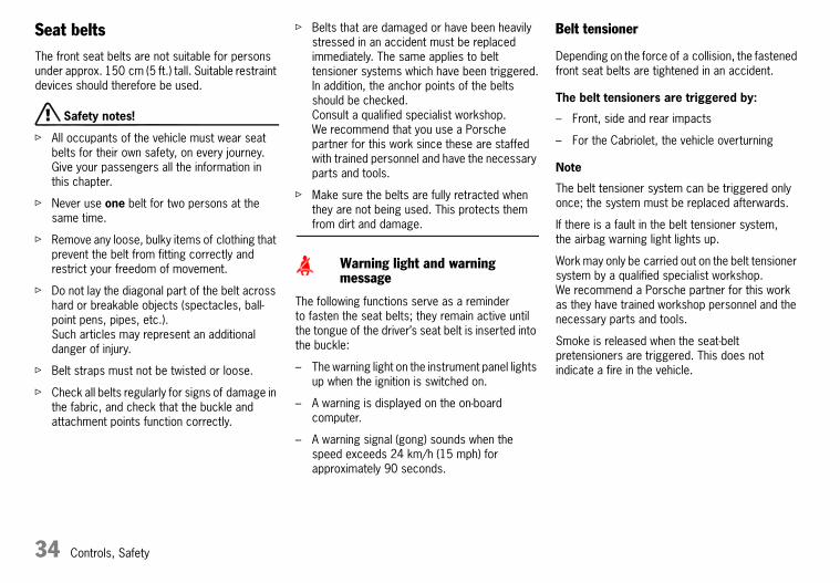
Seat beltsThe front seat belts are not suitable for persons under approx. 150 cm (5 ft.) tall. Suitable restraint devices should therefore be used.
d Safety notes!
f All occupants of the vehicle must wear seat belts for their own safety, on every journey.Give your passengers all the information in this chapter.
f Never use one belt for two persons at the same time.
f Remove any loose, bulky items of clothing that prevent the belt from fitting correctly and restrict your freedom of movement.
f Do not lay the diagonal part of the belt across hard or breakable objects (spectacles, ball-point pens, pipes, etc.). Such articles may represent an additional danger of injury.
f Belt straps must not be twisted or loose.
f Check all belts regularly for signs of damage in the fabric, and check that the buckle and attachment points function correctly.
f Belts that are damaged or have been heavily stressed in an accident must be replaced immediately. The same applies to belt tensioner systems which have been triggered.In addition, the anchor points of the belts should be checked. Consult a qualified specialist workshop. We recommend that you use a Porsche partner for this work since these are staffed with trained personnel and have the necessary parts and tools.
f Make sure the belts are fully retracted when they are not being used. This protects them from dirt and damage.
The following functions serve as a reminder to fasten the seat belts; they remain active until the tongue of the driver’s seat belt is inserted into the buckle:
– The warning light on the instrument panel lights up when the ignition is switched on.
– A warning is displayed on the on-board computer.
– A warning signal (gong) sounds when the speed exceeds 24 km/h (15 mph) for approximately 90 seconds.
Belt tensioner
Depending on the force of a collision, the fastened front seat belts are tightened in an accident.
The belt tensioners are triggered by:
– Front, side and rear impacts
– For the Cabriolet, the vehicle overturning
Note
The belt tensioner system can be triggered only once; the system must be replaced afterwards.
If there is a fault in the belt tensioner system, the airbag warning light lights up.
Work may only be carried out on the belt tensioner system by a qualified specialist workshop. We recommend a Porsche partner for this work as they have trained workshop personnel and the necessary parts and tools.
Smoke is released when the seat-belt pretensioners are triggered. This does not indicate a fire in the vehicle.
Warning light and warning message
10_Turbo_20.book Seite 34 Freitag, 7. August 2009 12:55 12

Controls, Safety 35
Fastening the seat belt
f Assume a comfortable sitting position.Please observe the chapter “SEAT POSITION” on Page 23.
f Adjust the seat backrest so that the belt always rests on your upper body and runs across the middle of your shoulder.
f Grasp the belt tongue and pull the belt in a slow, continuous motion across your chest and lap.
Note on operation
The belt can be blocked if the vehicle is standing at an angle or if the belt is pulled out using a jerking movement.
The belt cannot be pulled out while accelerating and slowing down, when cornering and when driving uphill.
f Insert the belt tongue into the appropriate buckle on the inboard side of the seat, until it locks securely with an audible click.
f Make sure that belts are not trapped or twisted, and that they are not rubbing on sharp edges.
f The horizontal section of the belt should always fit snugly across the pelvis. Therefore, after fastening the belt, always pull the diagonal part of the belt upwards.Pregnant women should position the belt as low as possible across the pelvis, and ensure that it is not pressing against the abdomen.
f Pull on the diagonal section of the belt now and again during the journey to ensure that the horizontal section remains tight.
Releasing the seat belt
f Hold the belt tongue.
f Press the red button (arrow).
f Guide belt tongue to the reel.
Seat belt height adjustment (Coupé)
Adjust the height of the seat belt so that it runs across the middle of the shoulder, not against the neck.
Adjusting belt height
f Upward – push belt deflector up.
f Downward – press button (arrow) and move belt deflector.
Cleaning the seat belts
f Please observe the chapter “CLEANING THE SEAT BELTS” on Page 198.
10_Turbo_20.book Seite 35 Freitag, 7. August 2009 12:55 12

36 Controls, Safety
Child Restraint System
Child restraint systems must not be used in bucket seats.
f Always switch off seat heating if a child restraint system is fitted.
f Seek appropriate advice from your Porsche partner about the possible installation of a Porsche child restraint system.
d Danger!
Risk of serious or mortal injury from the passenger airbag.
f The passenger airbag must always be switched off if a child restraint system is fitted on the passenger seat.Switching off will prevent the risk of serious or fatal injury potentially caused by the airbag.
Note
The key switch for switching off the passenger airbag and the Isofix attachment bracket are not installed at the factory. They can be retrofitted.
f Consult a qualified specialist workshop. We recommend a Porsche partner for this work as they have trained workshop personnel and the necessary parts and tools.
d Safety notes!
f Always observe the separate installation instructions for your child seat.
f Do not use child restraint systems in bucket seats.
f When using child restraint systems, it is vital that you observe the legal regulations that apply in your country.
f Use only child restraint systems recommended by Porsche.These restraint systems have been tested and adjusted to the interior of your Porsche and the appropriate child weight groups.Other systems have not been tested and could entail an increased risk of injury.
f If possible, always fit child seats for the weight groups I to III on the rear seats.
f Child seats for the weight group 0 and 0+ may only be fitted to the passenger seat.The passenger airbag must be switched off.
To switch off the passenger airbag:
f Please observe the chapter “SWITCHING PASSENGER AIRBAG ON AND OFF” on Page 38.
Children in weight group 0 and 0+:up to 13 kg
Children of this weight group must be held in a child restraint system that is installed on the passenger seat facing backwards.
f The passenger airbag must be switched off.
Children in weight group I:9 to 18 kg
Children in this weight group are carried in child restraint systems facing forward. Whenever possible, this child restraint equipment should be installed on the rear seats.
f The passenger airbag must be switched off when these systems are used on the passenger seat.
Children in weight group II:15 to 25 kg
Children in this weight group are carried in child restraint systems facing forward. Whenever possible, this child restraint equipment should be installed on the rear seats.
f The passenger airbag must be switched off when these systems are used on the passenger seat.
10_Turbo_20.book Seite 36 Freitag, 7. August 2009 12:55 12

Controls, Safety 37
Children in weight group III:22 to 36 kg
Children in this weight group are held in child restraint systems facing forwards.
Where possible, these child restraint systems should be installed on the rear seats.
f When a child seat is fitted to the passenger seat the passenger airbag must be switched off.
Recommended child restraint equipment
Weight groups and ages Manufacturer Type Authorisation number
Porsche Part No.
Fitted on passenger seat Installation on rear seat
Group 0 and 0+: up to 13 kgup to approx. 18 months
Britax Römer Porsche BabyseatISOFIX G0+
E1 04301146 955.044.802.86 Only if passenger airbag is switched off.Move passenger seat to lower rear position.
Not permitted
Group I: 9 to 18 kgapprox. 8 months to 4 years
Britax Römer Porsche Junior SeatISOFIX G1
E1 04301199 955.044.802.88 Only if passenger airbag is switched off.Move passenger seat to lower rear position.
Permitted
Group II: 15 to 25 kgapprox. 3.5 to 6 years
Britax Römer Porsche Junior PlusG2 + G3
E1 04301169 955.044.802.90 Only if passenger airbag is switched off.Move passenger seat to lower rear position.
Permitted
Group III: 22 to 36 kgapprox. 6 to 12 years
Britax Römer Porsche Junior PlusG2 + G3
E1 04301169 955.044.802.90 Move passenger seat to lower rear position.
Permitted
10_Turbo_20.book Seite 37 Freitag, 7. August 2009 12:55 12

38 Controls, Safety
Switching passenger airbag on and off
f Switch off the passenger airbag at the key switch using the vehicle key.
A - Switch position ON – airbag is active
B - Switch position OFF – airbag is not active
d Danger!
Risk of serious or mortal injury for passenger if passenger airbag remains switched off after the child seat is removed.
f The passenger airbag must be switched on again once the child seat has been removed.
“PASSENGER AIRBAG OFF” warning light
If the airbag is switched off on the passenger’s side, the “PASSENGER AIRBAG OFF” warning light is continuously lit when the ignition is switched on.
d Danger!
Risk of serious or mortal injury from the passenger airbag. If the “PASSENGER AIRBAG OFF” warning light is not lit when the ignition is switched on and the Airbag OFF switch is switched off, this could indicate a fault in the system.
f Do not install a child restraint system on the passenger seat.
f Have the fault remedied immediately. Consult a qualified specialist workshop. We recommend that you use a Porsche partner for this work since these are staffed with trained personnel and have the necessary parts and tools.
Note
The key switch and the “PASSENGER AIRBAG OFF” warning light are not installed at the factory. They can be retrofitted by your dealer (but not to vehicles with bucket seats).
10_Turbo_20.book Seite 38 Freitag, 7. August 2009 12:55 12

Controls, Safety 39
Isofix systemChild seat fixture on the passenger seat
Child restraint systems must not be used in bucket seats.
Use only child restraint systems with the Isofix system recommended by Porsche.These restraint systems have been tested and adjusted to the interior of your Porsche and the appropriate child weight groups.Other systems have not been tested and could entail an increased risk of injury.
You can obtain ISOFIX-compatible child seats from your Porsche partner.
f Always observe the separate installation instructions for your child seat.
Note
The ISOFIX fixture is not installed at the factory. It can be retrofitted by your dealer (but not to vehicles with bucket seats).
d Danger!
Risk of serious or fatal injury from passenger airbag if not switched off when using a child restraint system.
f The passenger airbag must be switched off if a child restraint system is fitted on the passenger seat.The vehicle seat must be adjusted to the lower rear position.
f Please observe the chapter “CHILD RESTRAINT SYSTEM” on Page 36.
Installing a child seat with Isofix system
1. Switch off passenger airbag with key switch.The warning light “PASSENGER AIRBAG OFF” must light up.Please observe the chapter “SWITCHING PASSENGER AIRBAG ON AND OFF” on Page 38.
2. Secure the child seat to retaining lugs A as outlined in the instruction manual for the child seat.
3. Pull the child seat to check that both fastening points are engaged correctly.
d Danger!
Risk of serious or mortal injury for passenger if passenger airbag remains switched off after the child seat is removed.
f The passenger airbag must be switched on again once the child seat has been removed.
10_Turbo_20.book Seite 39 Freitag, 7. August 2009 12:55 12

40 Controls, Safety
Airbag systems
General information
d Danger!
f Always fasten seat belts, because triggering of the airbag system depends on the force and angle of impact.
f Make sure there are no persons, animals or objects between the driver or passenger and the area into which the airbag inflates.
f Always hold the steering wheel by the outer rim.
f For airbags to give effective protection, they must be a certain distance from the driver or passenger.For this reason, select your seat position so that it is not unnecessarily close to the airbags.Do not lean against the inside of the doors (side airbags, head airbags).
f Always leave feet in the footwell when driving. Do not put feet on the dashboard or the seat cushion.
f Always keep the lid of the door oddments tray closed. Objects must not protrude out of the door oddments tray.
f Do not transport heavy objects on or in front of the passenger seat.
f Give your passenger all the information in this chapter.
f Always consult a qualified specialist workshop if the airbag system is faulty.
f Have triggered airbag systems replaced immediately.
f Do not modify the wiring or components of the airbag systems.
f Do not attach any additional trim or stickers to the steering wheel or in the vicinity of the passenger airbag, side airbags or head airbags.Do not use protective seat covers.
f Do not route any cables of additional electrical equipment in the vicinity of the airbag wiring harnesses.
f Do not remove airbag components such as the steering wheel, door linings or seats.
f If you sell your Porsche, tell the buyer that the vehicle is fitted with airbags and refer him to the chapter “Airbag systems” in the Driver’s Manual.
f Have the operational readiness of the system checked at the specified maintenance intervals.
f Please observe the chapter “CHILD RESTRAINT SYSTEM” on Page 36.
Function
In conjunction with the seat belts, the airbags are a safety system designed to provide the driver and passenger with maximum protection from injury in an accident.
Airbags protect the head and upper body, whilst simultaneously damping the motion of the driver and passenger in the impact direction in the event of a frontal impact or side impact.
The front airbags are installed under the padded steering wheel panel on the driver’s side and in the dashboard on the passenger’s side.
The side airbags (depending on vehicle equipment) are installed in the side of the seat backrests.
The head airbags are installed in the door lining.
The respective airbags could trigger depending on the angle of impact and force of impact.
After inflation, the front airbags deflate so quickly that any restriction of vision is insignificant. Equally, the inflating noise will be drowned out by the noise of the accident.
10_Turbo_20.book Seite 40 Freitag, 7. August 2009 12:55 12

Controls, Safety 41
Faults are indicated by the warning lights on the instrument panel and on the on-board computer.
f Please observe the chapter “WARNINGS ON THE INSTRUMENT PANEL AND THE ON-BOARD COMPUTER” on Page 134.
f Please consult a qualified specialist workshop in the following cases:
– If the warning light does not light up when the ignition key is inserted or
– If the warning light does not go out once the engine is running or
– If the warning light appears whilst driving.
Warning light “PASSENGER AIRBAG OFF”
f Please observe the chapter “SWITCHING PASSENGER AIRBAG ON AND OFF” on Page 38.
d Danger!
Risk of serious or mortal injury from the passenger airbag. If the “PASSENGER AIRBAG OFF” warning light is not lit when the ignition is switched on and the Airbag OFF switch is switched off, this could indicate a fault in the system.
f If the warning light does not come on, the child restraint system must not be used.
f Have the fault remedied immediately.
Risk of serious or mortal injury for passenger if passenger airbag remains switched off after the child seat is removed.
f The passenger airbag must be switched on again once the child seat has been removed.
Disposal
Non-ignited gas generators, or whole vehicles or subassemblies with airbag units, must not be disposed of as “normal” scrap or waste or put into any other form of end storage.Your Porsche partner will be able to give you details about disposal.
Warning light and warning message
10_Turbo_20.book Seite 41 Freitag, 7. August 2009 12:55 12

42 Controls, Safety
Roll-over protectionWith the Cabriolet, a roll-over protection system installed behind the rear seats is extended within fractions of a second in the event of accidents or extreme driving situations. If necessary, the seat-belt tensioners will be activated.
f Please observe the chapter “BELT TENSIONER” on Page 34.
Extreme driving situations include
– Extreme tilting or leaning (vehicle threatening to roll over to the side, or to roll over in the fore and aft direction),
– The vehicle lifting off the road (e.g. jumping over a hump).
The roll-over protection system consists of two roll-over bars that, together with the windscreen frame, ensure sufficient headroom for all occupants if the vehicle should roll over.
d Caution!
Risk of damage to the convertible top and roll-over bars.
f Do not open or close the convertible top with the roll-over bars extended.
d Safety notes!
f Always keep space clear for the roll-over bars to move.
f No modifications should be made to the wiring or components of the roll-over protection system.
f If the roll-over protection system is in any way faulty, consult a qualified specialist workshop. We recommend that you use a Porsche partner for this work since these are staffed with trained personnel and have the necessary parts and tools.
f Have the operational readiness of the system checked at the specified maintenance intervals.
If a fault is present in the roll-over protection system, the airbag warning light will light up on the instrument cluster. Extension of the roll-over bars is no longer ensured.
f Have the fault repaired without delay. Consult a qualified specialist workshop.
Pushing back the extended roll-over bars
f Consult a qualified specialist workshop. We recommend that you use a Porsche partner for this work since these are staffed with trained personnel and have the necessary parts and tools.
Warning message
10_Turbo_20.book Seite 42 Freitag, 7. August 2009 12:55 12

Controls, Safety 43
HandbrakeThe handbrake acts on the rear wheels and serves to secure the car from rolling away while parked.
Applying the handbrake
f Pull handbrake lever upwards.
Releasing the handbrake
f Pull handbrake lever slightly upwards, press the locking button and lower the lever completely.
The warning lights on the instrument panel and on the on-board computer are lit when the handbrake is on and go out when the handbrake is fully released.
f Please observe the chapter “WARNINGS ON THE INSTRUMENT PANEL AND THE ON-BOARD COMPUTER” on Page 134.
Warning light
10_Turbo_20.book Seite 43 Freitag, 7. August 2009 12:55 12

44 Controls, Safety
Footbrake
d Safety notes!
f Do not obstruct the pedal travel with floor mats or other objects.
The brake booster is ready for operation only while the engine is running. If the engine is switched off or there is a defect in the brake booster, much greater force has to be applied to the pedal when braking.
f Vehicles with defective brakes must not be towed.
f Please observe the chapter “TOWING AND TOW-STARTING” on Page 241.
In heavy rain, while driving through water or after leaving a car wash, the braking action may be delayed and increased pressure may be required.
f For this reason, keep further back from the vehicle in front and “dry” the brakes by applying them at short intervals. Make sure that following traffic is not affected.
After a long drive over salted or gritted roads, a coating may form on the brake discs and pads that significantly reduces friction and thus braking action.
f Even though the brake discs consist of alloyed grey cast iron, they will unavoidably start to corrode if your car is parked for an extended period. The brakes will tend to “judder” as a result.The nature, extent and effects of corrosion depend on the amount of time the vehicle was parked, whether road salt or grit was spread and whether grease-dissolving agents were used in car washes (not on cars with Porsche Ceramic Composite Brake).To prevent corrosion of the brake discs, “brake them dry” before parking the car (not on cars with Porsche Ceramic Composite Brake).If the braking comfort is noticeably impaired, we recommend having the brake system checked by experts.Consult a qualified specialist workshop. We recommend a Porsche partner for this work as they have trained workshop personnel and the necessary parts and tools.
f To relieve the brake system on downhill stretches, change down to a lower gear in good time to obtain engine braking.If engine braking is insufficient on steep stretches, operate the footbrake at intervals. Continuous braking overheats the brakes and reduces the braking effect.
f Please observe the chapter “BRAKE FLUID LEVEL” on Page 184.
10_Turbo_20.book Seite 44 Freitag, 7. August 2009 12:55 12

Controls, Safety 45
Brake pads and brake discs
Wear on the brake pads and brake discs depends to a great extent on the driving style and the conditions of use and therefore cannot be expressed in actual miles on the road.
The high-performance brake system is designed for optimal braking effect at all speeds and temperatures.Certain speeds, braking forces and ambient conditions (such as temperature and humidity) therefore might cause the brakes to “squeal”.
When the wear limit for the pads has been reached, the warning lights on the instrument panel and on the on-board computer will light up.
f Please observe the chapter “WARNINGS ON THE INSTRUMENT PANEL AND THE ON-BOARD COMPUTER” on Page 134.
f Have the brake pads replaced without delay. Consult a qualified specialist workshop. We recommend a Porsche partner for this work as they have trained workshop personnel and the necessary parts and tools.
Checks on test stands
Brake tests must be performed only on roller test stands.
The ignition must be switched off.
The following limit values must not be exceeded on roller test stands:
– Testing speed 8 km/h (5 mph)
– Test duration 20 seconds
Handbrake tests on the brake test stand must only be carried out with the ignition switched off.Warning light
10_Turbo_20.book Seite 45 Freitag, 7. August 2009 12:55 12

46 Controls, Safety
ABS Brake System
(anti-lock brake system)
d Safety notes!
In spite of the advantages of ABS, it is still the driver’s responsibility to adapt his driving style and manoeuvres to match the road and weather conditions, as well as the traffic situation.
The increased safety that is provided should not induce you to take greater risks with your safety. The limits set by the physics of driving cannot be overcome, even with ABS.Risks of accident due to inappropriate speed cannot be reduced by ABS.
ABS ensures
Full steering control
– The vehicle remains steerable
Excellent driving stability
– No skidding due to locked wheels
Optimum braking distance
– Shorter stopping distances in most cases
Lock prevention
– No flat spots on the tyres
Function
The decisive advantage of ABS lies in the driving stability and manoeuvrability of the vehicle in hazardous situations.
The ABS prevents locking of the wheels during full braking, on almost all road surfaces, until shortly before the vehicle stops.
The ABS begins to control the braking process as soon as a wheel shows a tendency to lock. This controlled braking process is comparable with extremely rapid cadence braking. The pulsating brake pedal and a “juddering noise” warn the driver to adapt his driving speed to the road conditions.
f If full braking is necessary, fully depress the brake pedal during the whole braking operation, even though the pedal is pulsating. Do not reduce the pedal pressure.
If the ABS warning lights light up on the instrument panel and on the on-board computer while the engine is running, the ABS has switched off because of a fault.In this case, the brake system will operate without lock prevention, as in vehicles without ABS.
f Adapt your driving style to the changed braking behaviour.The ABS must be checked by your Porsche partner in order to prevent the occurrence of further faults with unpredictable consequences.
f Consult a qualified specialist workshop. We recommend a Porsche partner for this work as they have trained workshop personnel and the necessary parts and tools.
The ABS control unit is adjusted for the approved tyre dimensions. The use of tyres with non-approved dimensions can lead to different wheel speeds, causing ABS to switch off.
Warning light
10_Turbo_20.book Seite 46 Freitag, 7. August 2009 12:55 12

Controls, Safety 47
Sport modeA sportier car set-up is obtained when Sport mode is switched on. Interventions by the Porsche control systems are intentionally shifted towards greater agility and driving performance:
– PASM (Porsche Active Suspension Management) is automatically changed to Sport mode, resulting in a stiffer suspension setup.
– The PDK transmission switches to a sporty gear-changing map and shortens the gear shifting times when Sport mode is activated. Gear changes take place faster.PSM (Porsche Stability Management) control is sporty. PSM interventions take place later than in Normal mode. The driver can manoeuvre the vehicle with greater agility at its performance limits, without having to dispense with the assistance of PSM in emergency situations. This helps to achieve optimal lap times, particularly on race circuits with a dry road surface.
– The electronic accelerator pedal reacts sooner, and the engine is more responsive to throttle inputs. When Sport mode is switched on, this function is activated only after the driver has floored the accelerator pedal or released it briefly.
– The rpm limiter characteristic is “harder”. i.e. the engine is immediately throttled when the performance limits are reached (only in manual selection mode and without kickdown actuation for vehicles with PDK transmission).
– PTM (Porsche Traction Management) provides a more rear-biased drive-torque distribution. This gives the vehicle a balance with greater agility, and sporty oversteer is also possible.
– The dynamic engine mountings are damped more intensely, resulting in a more compact engine and body unit. In dynamic driving manoeuvres the vehicle responds with greater agility and more precisely.
f Please refer to the chapters on PSM, PASM, PTM, PADM and PDK.
– The overboost briefly increases the engine boost pressure by approx. 0.2 bar (3 psi) in the engine speed range from 2000 rpm to approx. 4500 rpm. This increases torque in this speed range by 50 Nm. This considerably improves acceleration and flexibility, particularly in the medium engine speed range. This does not affect the maximum power. Quickly flooring the accelerator pedal activates the overboost function in the engine control unit.
An arrow appears next to the boost pressure display. Overboost has an effective operating time of approx. 10 seconds. After this time, it can be re-activated by quickly flooring the accelerator pedal again.
10_Turbo_20.book Seite 47 Freitag, 7. August 2009 12:55 12

48 Controls, Safety
Switching Sport mode on and off
Switching Sport mode on and off simultaneously activates and deactivates the Sport mode in PASM.If PASM Sport mode was activated with the PASM button, PASM remains active.
After the ignition is switched off, Sport mode is automatically reset to Normal mode.
SPORT button
f Press the SPORT button A in the centre console.When Sport mode is switched on, the light-emitting diode in the SPORT button is lit. On vehicles equipped with a manual transmission, the logo SPORT appears next to the digital speedometer.
A sporty gear-changing map is enabled and the gear shifting times are shortened for the PDK transmission.A sporty driving style is recognised more quickly and the gear-changing speeds are adapted to driving performance.
Deceleration downshifts are initiated earlier. Downshifts are already carried out in the case of slight decelerations, even at higher engine speeds.
f Please observe the chapter “SPORT MODE (“SPORT” AND “SPORT PLUS” MODE)” on Page 148.
SPORT PLUS button (only on vehicles with PDK transmission)
In “Sport Plus” mode, the PDK transmission changes to a shift programme designed for driving on race circuits. 7th gear is not selected.The gear-changing performance is enhanced significantly again compared with “Sport” mode.
f Please observe the chapter “SPORT MODE (“SPORT” AND “SPORT PLUS” MODE)” on Page 148.
f Press the SPORT PLUS button B in the centre console.When “Sport” mode is switched on, the light-emitting diode in the SPORT PLUS button is lit.
SPORT/SPORT PLUS display on the PDK steering wheel with shift buttons
When Sport mode is switched on, the logo SPORT/SPORT PLUS appears on the multi-function display.
10_Turbo_20.book Seite 48 Freitag, 7. August 2009 12:55 12

Controls, Safety 49
SPORT/SPORT PLUS display on the PDK steering wheel with shift paddles
When Sport mode is switched on, the logo SPORT/SPORT PLUS appears on the multi-function display.
Porsche Stability Management (PSM)PSM is an active control system for stabilisation of the vehicle during extreme driving manoeuvres.
d Safety instruction!
In spite of the advantages of PSM, it is still the driver’s responsibility to adapt his driving style and manoeuvres in line with road and weather conditions, as well as the traffic situation.
The increased safety that is provided should not induce you to take greater risks with your safety. The limits set by the physics of driving cannot be overcome, even with PSM.Risks of accident due to inappropriate speed cannot be reduced by PSM.
Sensors at the wheels, brakes, steering system and engine continuously measure:
– Speed
– Direction of travel (steering angle)
– Lateral acceleration
– Rate of turn about the vertical axis
– Longitudinal acceleration
PSM uses these values to determine the direction of travel desired by the driver.PSM intervenes and corrects the course if the actual direction of motion deviates from the desired course (steering-wheel position):
It brakes individual wheels as needed. In addition, the engine power may be manipulated in order to stabilise the vehicle.
The events below inform the driver of PSM control operations and warn him to adapt his driving style to the road conditions:
– The multifunctional information light on the instrument panel flashes.
– Hydraulic noises can be heard.
– The vehicle decelerates and steering-wheel forces are altered as the PSM controls the brakes.
– Reduced engine power.
– The brake pedal pulsates and its position is changed during braking.In order to achieve full vehicle deceleration, foot pressure must be increased after the brake pedal has begun vibrating.
10_Turbo_20.book Seite 49 Freitag, 7. August 2009 12:55 12

50 Controls, Safety
Examples of PSM control operations
– If the front wheels of the vehicle drift on a bend, the rear wheel on the inside of the bend is braked and the engine power is reduced if necessary.
– If the rear of the vehicle swings out on a bend, the front wheel on the outside of the bend is braked.
Additional braking functions
– Pre-filling the brake system:The brake system is prepared for possible subsequent emergency braking if the accelerator pedal is released suddenly and quickly. The brake system is prefilled and the brake pads are already applied gently to the brake discs.
– Brake booster:In the event of an emergency braking operation where the pedal force is insufficient, a brake booster provides the braking pressure necessary for maximum deceleration at all 4 wheels.
Advantages of PSM
– Best possible traction and lane-holding ability in all driving situations – even on road surfaces with varying friction.
– The system compensates for undesired vehicle reactions (Ferraria effect) when the driver releases the accelerator pedal or brakes on bends. This compensation functions up to the maximum lateral acceleration.
– PSM actively stabilises the vehicle if necessary during dynamic driving manoeuvres (e.g. rapid steering movements, during lane changes, or on alternating bends).
– Improved braking stability on bends and on different or varying road surfaces.
– It improves braking function and shortens stopping distance in the event of emergency braking.
Readiness for operation
PSM is switched on automatically every time you start the engine.
PSM should always be switched on during “normal” driving.
However, it may be advantageous to switch off PSM temporarily in exceptional situations, for example:
– On a loose surface or in deep snow,
– When “rocking” the vehicle free and
– When using snow chains.
Switching off PSM
f Press PSM OFF button. PSM is switched off after a short delay.The light-emitting diode in the button is lit up.When the PSM is switched off, the PSM multifunctional light on the instrument panel is lit and a message is shown on the on-board computer.An acoustic signal also sounds.
Note
When PSM is switched off, the additional braking functions are deactivated. Automatic reactivation in emergency situations is coupled to the PSM control.
10_Turbo_20.book Seite 50 Freitag, 7. August 2009 12:55 12

Controls, Safety 51
The following functions stabilise the vehicle in emergency situations, even with PSM switched off:
– When PSM is off, the vehicle is stabilised as soon as one of the two front wheels enters the ABS control range.
– When PSM is off and Sport mode is on, the vehicle is stabilised as soon as both front wheels enter the ABS control range.
One-sided spinning of the wheels is prevented, even with PSM switched off.
Switching PSM back on
f Press PSM OFF button. PSM is switched on after a short delay.The light-emitting diode in the button and the PSM multifunctional light on the instrument panel go out.The on-board computer shows a message.
Sport mode
A sportier car setup is obtained when Sport or Sport Plus mode is switched on. PSM interventions are later than in Normal mode; the vehicle can be manoeuvred with greater agility at its performance limits, without the need to dispense with the assistance of PSM in emergency situations. This helps to achieve optimal lap times, particularly on race circuits and a dry road surface.
– The multifunctional light on the instrument panel lights up for a lamp check when the ignition is switched on.
– The light indicates a control operation by flashing, including when PSM is switched off (brake control in the event of one-sided wheel spin).
– In conjunction with a message on the on-board computer, the light indicates that PSM is switched off.An acoustic signal also sounds.
– The light indicates a fault in conjunction with a message on the on-board computer.PSM is out of order.
f Consult a qualified specialist workshop. We recommend a Porsche partner for this work as they have trained workshop personnel and the necessary parts and tools.
f Please observe the chapter “PUTTING VEHICLE INTO OPERATION” on Page 225.
Towing
f Please observe the chapter “TOWING AND TOW-STARTING” on Page 241.
Checks on test stands
Brake tests must be performed only on roller test stands.
The following limit values must not be exceeded on roller test stands:
– Testing speed 8 km/h (5 mph)
– Test duration 20 seconds
Handbrake tests on the brake test stand must only be carried out with the ignition switched off.
PSM multifunctional light
10_Turbo_20.book Seite 51 Freitag, 7. August 2009 12:55 12

52 Controls, Safety
PASM makes two running-gear setups available to the driver: “Normal” and “Sport”.The selection is made via a button on the centre console.
In Normal mode the running gear is in a sporty and comfortable setup.Sport mode offers very sporty shock absorber tuning (e.g. for driving on the race circuit).
The variable suspension system selects the appropriate damping level for each wheel according to the situation and conditions of driving.
Example:If the vehicle is driven in a very sporty manner in Normal mode, PASM automatically adapts the shock-absorber behaviour to the driving situation in this case as well.
Switching on PASM Sport mode
f Press PASM button in the centre console.When PASM Sport mode is switched on, the light-emitting diode in the button is lit up and a message is shown on the on-board computer.
Switching off PASM Sport mode
f Press PASM button in the centre console.The light-emitting diode in the button goes out and the on-board computer displays a message.
After the ignition is switched off, PASM is automatically reset to Normal mode.
Porsche Traction Management (PTM)With PTM, the drive power is variably distributed to the front and rear wheels.Power distribution between the front and rear axles is performed by a map-controlled multiple-disc clutch. Distribution of the drive power also depends on the difference in wheel speed between the two axles. The multiple-disc clutch always delivers sufficient drive power to the front wheels to ensure optimum propulsion even on an unfavourable road surface.
In combination with Porsche Stability Management (PSM) and Porsche Torque Vectoring (PTV), the PTM ensures optimum handling and high driving stability.
d Danger!
In spite of the advantages of PTM, it is still the driver’s responsibility to adapt his/her driving style and manoeuvres in line with road and weather conditions, as well as the traffic situation.
The increased safety that is provided should not induce you to take greater risks with your safety. The limits set by the physics of driving cannot be overcome, even with PTM.Risks of accident due to inappropriate speed cannot be reduced by PTM.
Porsche Active Suspension Management (PASM)
10_Turbo_20.book Seite 52 Freitag, 7. August 2009 12:55 12

Controls, Safety 53
Porsche Torque Vectoring (PTV)PTV consists of a control system for driving-dynamics relevant brake interventions enabling variable drive-torque distribution at the rear axle and a mechanical rear-axle differential lock.
By using gentle braking interventions that are imperceptible to the driver at the rear wheel on the inside of the bend, PTV improves steering performance and steering precision. The vehicle follows the steering angle of the front wheels more precisely. Understeer is almost fully prevented in limit situations. This in turn enhances the lateral-acceleration potential. Higher cornering speeds are then possible.
The mechanical rear-axle differential lock improves traction in the case of wheel spin. When driving quickly through corners, it reduces the load reversal reactions and at higher speeds it increases driving stability.
d Danger!
Despite the advantages of PTV, it is still the driver’s responsibility to adapt his/her driving style and manoeuvres in line with road and weather conditions, as well as the traffic situation.
The increased safety that is provided should not induce you to take greater risks with your safety. The limits set by the physics of driving cannot be overcome, even with PTV.Risks of accident due to inappropriate speed cannot be reduced by PSV.
Dynamic Engine Mounting (PADM)Dynamic Engine Mounting with variable damping is a system designed to enhance both driving dynamics and driving comfort. Depending on the driving situation, the ideal mounting rigidity and damping is automatically selected in the range between an almost rigid engine-to-body connection (increase in driving dynamics) and decoupling of the engine from the body (increase in driving comfort).
Warning message
Dynamic engine mounting faults are indicated by a warning message on the on-board computer.
f Please observe the chapter “WARNINGS ON THE INSTRUMENT PANEL AND THE ON-BOARD COMPUTER” on Page 134.
Checks on test stands
Brake tests
Brake tests must be performed only on roller test stands.
The ignition must be switched off.
The following limit values must not be exceeded on roller test stands:
– Testing speed 8 km/h (5 mph)
– Test duration 20 seconds
Handbrake check
Handbrake tests on the roller brake tester must only be carried out with the ignition switched off.
Balancing wheels on the vehicle
During finish balancing of the wheels, the vehicle must be lifted and the wheels must be free to turn.
10_Turbo_20.book Seite 53 Freitag, 7. August 2009 12:55 12

54 Controls, Safety
Towing
f Please observe the chapter “TOWING AND TOW-STARTING” on Page 241.
Wheels/tyres
The PTM control unit is adapted to the approved tyre sizes. The use of non-approved tyre sizes may lead to deviations in wheel speeds and it may influence handling or result in the PTM switching off.
Retractable Rear SpoilerThe rear spoiler improves driving stability, especially at higher speeds.
d Warning!
Risk of accident. If the rear spoiler cannot be extended, driving stability will be adversely affected by increased rear axle lift.
f Adapt your driving style and speed to the changed driving conditions.
f Have the fault remedied. Consult a qualified specialist workshop. We recommend a Porsche partner for this work as they have trained workshop personnel and the necessary parts and tools.
Risk of injury during manual retraction or extension of the rear spoiler with the vehicle stationary.
f Make sure that no persons or objects are within the range of movement of the rear spoiler.
Risk of damage from pushing the vehicle by the spoiler.
f Do not push the vehicle at the spoiler.
Automatic mode
Automatic extension and retraction of the spoiler depend on various circumstances (e.g. driving speed, engine compartment temperature).
Engine compartment temperature below 55 °C
Spoiler extends at 120 km/h (75 mph) and retracts at 60 km/h (40 mph).
Engine compartment temperature above 60 °C
Spoiler extends at 80 km/h (50 mph) and retracts at 30 km/h (20 mph).
If automatic control fails, a warning message is displayed by the on-board computer.
10_Turbo_20.book Seite 54 Freitag, 7. August 2009 12:55 12

Controls, Safety 55
When the ignition is on, the rear spoiler can be extended and retracted manually using the button in the centre console.
Extending
f Press button briefly.The spoiler extends to its final position.The light-emitting diode in the button lights up.
Retracting a manually extended rear spoiler
f At speeds between 0 and 30 km/h (0 and 20 mph)Press and hold button until the rear spoiler has reached its final position.The light-emitting diode in the button goes out. The rear spoiler changes to automatic mode.
f At speeds between 30 and 100 km/h (20 and 60 mph)Press button briefly.The rear spoiler retracts, the light-emitting diode in the button goes out. The rear spoiler changes to automatic mode.
f At speeds over 100 km/h (60 mph)Press button briefly.The rear spoiler remains extended, the light-emitting diode in the button goes out. The rear spoiler changes to automatic mode.
Manual control
10_Turbo_20.book Seite 55 Freitag, 7. August 2009 12:55 12

56 Controls, Safety
A, C - Switch for reading light on driver/passenger sideB - Switch for interior light and footwell lightsD - Orientation light
Interior lightsf Please observe the chapter “LOAD SWITCH-
OFF AFTER 2 HOURS OR 7 DAYS” on Page 220.
For vehicles with automatic anti-dazzle mirrors
f Switch off the automatic anti-dazzle operation of the mirrors before you switch on the interior light.Otherwise the mirrors may accidentally swivel into the anti-dazzle position.
Interior lights, reading lights
Switching off
f Press left half of switch.
Switching to continuous illumination
f Press right half of switch.
Switching on and off automatically
f Move switch to centre position.
The interior and footwell lights are switched on when a door is unlocked or opened or when the ignition key is withdrawn from the ignition lock.
The interior lights are switched off with a delay of approx. 2 minutes after the doors are closed.The interior lights go out immediately as soon as the ignition is switched on or the vehicle is locked.
Orientation light
A light-emitting diode at the bottom of the interior mirror improves orientation in the passenger compartment when it is dark.
Note on operation
On vehicles with Sport Chrono Turbo package, the brightness of the orientation light can be changed in PCM.
f Please observe the chapter “Individual Memory” in the separate PCM operating instructions.
10_Turbo_20.book Seite 56 Freitag, 7. August 2009 12:55 12

Controls, Safety 57
Parking Aids
ParkAssist
When the driver backs up, ParkAssist indicates the distance between the car and an obstacle by means of signal tones.
d Warning!
Risk of accident. Even when using ParkAssist, the driver is still responsible for taking due care when parking and when assessing obstacles.
f Make sure that no persons, animals or obstacles are within the manoeuvring area.
ParkAssist is activated automatically when reverse gear is selected and the ignition is on.
Note
ParkAssist is not switched on if the car rolls backward without reverse gear engaged.
Ultrasound sensors
Sensors
Four ultrasound sensors in the rear bumper measure the distance to the closest obstacle.
– Range of middle sensors: Approx. 150 cm
– Range of outer sensors: Approx. 60 cm
Obstacles cannot be detected within the blind sensor area (e.g. near the ground).
f The sensors must always be kept free of dust, ice and snow in order to ensure that they are fully functional.
f Do not damage sensors by abrasion or scratching.
f To avoid damaging the sensors, maintain sufficient distance when cleaning with steam-jet units.
Signal tones/function
When reverse gear is selected, ParkAssist confirms that it is switched on by issuing a short signal tone.
A detected obstacle is signalled by an intermittent tone. The intervals decrease as the obstacle is approached. If the distance drops to less than approx. 30 cm), a continuous tone sounds. This continuous tone can stop if the obstacle is approached even closer.
f Set the radio volume so that the signal tones are not drowned out.
Limits of ultrasonic measurement
– ParkAssist cannot detect sound-absorbing obstacles (e.g. winter driving, powder snow),
– sound-reflecting obstacles (e.g. glass surfaces, flat painted surfaces),
– and very thin obstacles.
Other sources of ultrasound (e.g. pneumatic brakes of other vehicles and jackhammers) may interfere with detection of obstacles.
10_Turbo_20.book Seite 57 Freitag, 7. August 2009 12:55 12
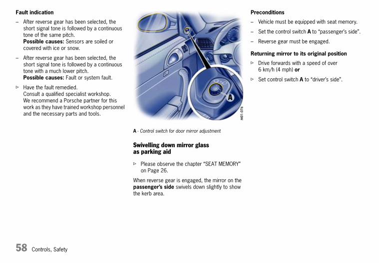
58 Controls, Safety
Fault indication
– After reverse gear has been selected, the short signal tone is followed by a continuous tone of the same pitch.Possible causes: Sensors are soiled or covered with ice or snow.
– After reverse gear has been selected, the short signal tone is followed by a continuous tone with a much lower pitch.Possible causes: Fault or system fault.
f Have the fault remedied.Consult a qualified specialist workshop. We recommend a Porsche partner for this work as they have trained workshop personnel and the necessary parts and tools.
A - Control switch for door mirror adjustment
Swivelling down mirror glass as parking aid
f Please observe the chapter “SEAT MEMORY” on Page 26.
When reverse gear is engaged, the mirror on the passenger’s side swivels down slightly to show the kerb area.
Preconditions
– Vehicle must be equipped with seat memory.
– Set the control switch A to “passenger’s side”.
– Reverse gear must be engaged.
Returning mirror to its original position
f Drive forwards with a speed of over 6 km/h (4 mph) or
f Set control switch A to “driver’s side”.
10_Turbo_20.book Seite 58 Freitag, 7. August 2009 12:55 12

Controls, Safety 59
0 - Initial position1 - Ignition on2 - Start engine3 - Ignition off
Ignition Lock/Steering LockThe ignition lock has a total of four ignition lock positions.The vehicle key rebounds to the initial position from every ignition lock position.
Ignition lock position 0
Initial position
The ignition key cannot be withdrawn when the ignition is switched on or when the engine has been started.
To withdraw the ignition key:
f Stop the vehicle.
f On vehicles with PDK transmission:Move PDK selector lever to position P.
f Switch ignition off.
f Remove ignition key.
Ignition lock position 1
Ignition on
f Turn ignition key to position 1.Ignition is switched on.
Note on operation
All electrical equipment can be switched on.
f Please observe the chapter “WARNINGS ON THE INSTRUMENT PANEL AND THE ON-BOARD COMPUTER” on Page 134.
Ignition lock position 2
Start engine
f Turn ignition key to ignition lock position 2.
f Please observe the chapter “STARTING AND STOPPING THE ENGINE” on Page 61.
Ignition lock position 3
Ignition off
f Turn ignition key to ignition lock position 3.
Locking the steering column
Automatic locking
The steering column is automatically locked when the ignition key is withdrawn from the ignition lock.
f Withdraw the ignition key only when the vehicle is stationary, otherwise the steering lock engages and the vehicle cannot be steered.
f When leaving the vehicle the ignition key must always be removed.
Automatic unlocking
f The steering column is unlocked when the vehicle is unlocked with the radio remote control.
10_Turbo_20.book Seite 59 Freitag, 7. August 2009 12:55 12

60 Controls, Safety
Emergency operation – releasing the ignition key
If the vehicle battery is dead, the key can be pulled out only if the emergency operation is performed.
1. Grasp the fuse box cover at the finger hole and pull it off.
2. Unclip metal hook A on the inside of the cover.
3. Use metal hook A to remove the plastic cover B from the ignition lock.Make sure that plastic cover B is not lost.
4. Turn ignition key anti-clockwise as far as it will go.
5. Press metal hook A into opening C.An unlocking sound will be heard.
6. Turn the ignition key to initial position 0 and remove.
7. Re-fit the plastic cover B.
10_Turbo_20.book Seite 60 Freitag, 7. August 2009 12:55 12

Controls, Safety 61
Starting and Stopping the Enginef Please observe the chapter “IMMOBILISER”
on Page 10.
f Please observe the chapter “FUEL” on Page 186.
d Warning!
Risk of poisoning. Exhaust gas contains colourless and odourless carbon monoxide, which is toxic even in low concentrations.
f Never start the engine or let it run in confined spaces.
Danger of fire in the area of the hot exhaust system.
f Do not park or drive your car where combustible materials, such as dry grass or leaves, can come into contact with the hot exhaust system.
Danger of burns near tailpipes or in the event of contact with tailpipes. Tailpipes are hot when the engine is running and for some time after the engine is switched off.
f Keep a safe distance away from the tailpipes when you are behind the vehicle.
f Make sure that children do not burn themselves on the tailpipes.
Starting
f Operate footbrake.
f Fully depress the clutch pedal and put the gearshift lever into neutral. Keep the clutch pedal depressed while you are starting the vehicle.
f Move the PDK selector lever to the P or N position.
f Do not press the accelerator pedal.
f Do not operate the starter for more than approx. 10 seconds. If necessary, repeat the starting procedure after a pause of approx. 10 seconds. Turn the ignition key back to the 3 position first.
The first operation of the starter is ended automatically when the engine starts.If the engine does not start, subsequent starter operations will not be ended automatically.
f Do not warm up the engine when stationary. Drive off immediately. Avoid high revolutions and full throttle until the engine has reached operating temperature.
If battery output is insufficient, jump leads can be used to start the engine (Vehicles with manual transmission can also be tow-started).
f Please observe the chapter “JUMP LEAD STARTING” on Page 228.
f To ensure a good charge condition for the battery and thus its ability to start the engine, all electrical accessories which are not required should be switched off when the ignition is switched on and when engine revolutions are low (in traffic jams, in cities or in queues).
10_Turbo_20.book Seite 61 Freitag, 7. August 2009 12:55 12

62 Controls, Safety
Stopping
f Only switch the ignition off when the vehicle is stationary, as there is no steering assistance and brake boost when the engine is switched off.
f Withdraw the ignition key only when the vehicle is stationary, otherwise the steering lock engages and the vehicle cannot be steered.
f Always remove the ignition key and engage the parking brake when leaving the vehicle. On vehicles with manual transmission, engage 1st gear or reverse gear, or on vehicles with PDK transmission, engage selector lever position P.
Note
The vehicle battery will be discharged rapidly if the ignition key is left inserted.
f Please observe the chapter “LOAD SWITCH-OFF AFTER 2 HOURS OR 7 DAYS” on Page 220.
Engine-compartment blower, radiator fans
The radiators and radiator fans are in the front of the vehicle.The engine-compartment blower is mounted on the engine compartment lid.
d Warning!
Risk of injury. After the engine is switched off, the engine compartment temperature is monitored for approx. 30 minutes.During this period, and depending on temperature, the engine-compartment blower may continue to run or start to run.
f Carry out work in these areas only with the engine off and exercise extreme caution.
Risk of injury. The radiator fans in the front end of the car may be operating or unexpectedly start operating when the engine is switched on.
f Carry out work in these areas only with the engine switched off.
10_Turbo_20.book Seite 62 Freitag, 7. August 2009 12:55 12

Controls, Safety 63
Warning gong
If the ignition key is withdrawn and the door is opened while the lights (not for Home mode) are on, a gong warns of possible battery discharge.
In some countries, differences are possible due to provisions of law.
Daytime driving lights
Only the LED lights integrated into the front auxiliary headlights come on in light switch setting OFF or HOME.Dipped beam headlights must be switched on when driving through tunnels or at dusk, for example.
Operation of the daytime driving lights may vary depending on country-specific regulations.
Note on operation
The daytime driving lights can be deactivated on the on-board computer.
f Please observe the chapter “ON-BOARD COMPUTER” on Page 102.
Cornering light
The dynamic cornering light is activated above speeds of 10 km/h (6 mph).
Home mode
Switching on Home mode
f Move light switch to the HOME position.
For improved visibility and safety when you get in and out of the car, the daytime driving lights and the tail lights remain on for a certain period of time:
– When you get out of the car, the lights are turned on for approx. 30 seconds after the door is opened. The off-delay time recommences when the vehicle is locked.On vehicles with the Sport Chrono Turbo package, the PCM can be used to set the off-delay time. This setting also changes the lighting period for unlocking the vehicle.Please observe the chapter “Individual Memory” in the separate PCM operating instructions.
f When the vehicle is unlocked, the lights are turned on for approx. 30 seconds.The lights go out if the ignition is switched on or if you leave Home mode.
Light switchLight is switched off
Daytime driving lights are switched on when the engine is running.
Home mode
Daytime driving lights are switched on when the engine is running.
Side light
Number plate light, side light, instrument illumination switched on, daytime driving lights switched off.
Dipped beam, high beam
Only when ignition is switched on, daytime driving lights switched off.
Rear fog light
Pull switch.Indicator light comes on.
10_Turbo_20.book Seite 63 Freitag, 7. August 2009 12:55 12

64 Controls, Safety
Headlight beam adjustmentYour Porsche is equipped with dynamic headlight beam adjustment.
When the ignition is switched on, the level of the headlight beam automatically changes in accordance with the vehicle load.The level of the headlight beam is automatically kept constant during acceleration and braking.
Checking operation
1. Switch the dipped beam on.
2. Insert ignition key and switch on ignition.The light beam first dips all the way down and is then adapted to the vehicle load.
If this test point is not satisfied, the headlight beam adjustment system must be checked.
f Consult a qualified specialist workshop. We recommend a Porsche partner for this work as they have trained workshop personnel and the necessary parts and tools.
Direction Indicator/High Beam/Parking Light/Headlight Flasher StalkDirection indicators, dipped beam and high beam are ready for operation when the ignition is on.
1 – Direction indicator left2 – Direction indicator rightPush the stalk to the upper or lower pressure point – direction indicators flash three times
3 – High beam4 – Headlight flasherStalk in centre position – dipped beam
When high beam and headlight flasher are selected, the blue indicator light in the tachometer is lit.
Parking light
The parking light can only be switched on when the ignition is switched off.
f Move the stalk up or down to switch on the right or left parking light.
Individual Light FunctionsFurther individual light functions are available in vehicles with the Sport Chrono Turbo package.
f Please observe the chapter “Individual Memory” in the separate PCM operating instructions.
10_Turbo_20.book Seite 64 Freitag, 7. August 2009 12:55 12

Controls, Safety 65
Windscreen Wiper/Washer Stalk
d Caution!
Danger of injury if windscreen wipers start to wipe unexpectedly, e.g. in intermittent or rain sensor operation.Risk of damage to the windscreen, wiper system and headlight washer.
f Only wipe the windscreen when sufficiently wet, otherwise it could be scratched.
f Loosen frozen wiper blades before driving off.
f Always switch off windscreen wipers in car washes to prevent them wiping unintentionally (sensor operation).
f Always switch off windscreen wipers before cleaning the windscreen to avoid unintentional operation (sensor operation).
f Do not operate the headlight washer in car washes.
f Do not operate headlight washer when it is frozen.
Front wiper and headlight washer system
0 – Windscreen wipers off1 – Rain sensor operation, front windscreen
wipersMove wiper stalk upwards to the first click.
2 – Front windscreen wiper – slowMove wiper stalk upwards to the second click.
3 – Front windscreen wiper – fastMove wiper stalk upwards to the third click.
4 – Front windscreen wipers – one-touch operationMove wiper stalk downwards.The front windscreen wipers wipe once.
5 – Front windscreen wiper and washer systemPull wiper stalk towards the steering wheel. The washer system sprays and wipes while the stalk is pulled towards the steering wheel. When the wiper stalk is released, a few drying wipes are performed.
A – Headlight washer system
The washer sprays only while dipped beam or high beam is switched on.
f Briefly push button A to operate headlight washer system.
f If heavily soiled, repeat wash.
The headlight washer system automatically sprays once for every ten times the front windscreen washer system is operated.
Note
The front windscreen washer nozzles are heated when the ignition is on, as a precaution against freezing.
10_Turbo_20.book Seite 65 Freitag, 7. August 2009 12:55 12

66 Controls, Safety
Rear wiper
6 – Rear window wiper – intermittent operationMove wiper stalk forward.The rear window wiper wipes at preset intervals.
If a speed of 210 km/h (130 mph) is exceeded, the rear wiper is switched off automatically and is switched on again when the speed falls below 200 km/h (125 mph).
On vehicles with the Sport Chrono Turbo package, further rear wiper functions can be selected via the PCM.
f Please observe the chapter “Individual Memory” in the separate PCM operating instructions.
10_Turbo_20.book Seite 66 Freitag, 7. August 2009 12:55 12

Controls, Safety 67
Rain sensor
The rain sensor on the windscreen measures the amount of rainfall (and snowfall). Wiper speed is automatically adjusted accordingly.
Switching on
f Move wiper stalk upwards to the first click.
Switching off
f Move wiper stalk to position 0.
The rain sensor remains switched off if the wiper stalk is already in position 1 when the ignition is switched on.
To switch the rain sensor on again:
f Move wiper stalk to position 0 and then to position 1 or
f Operate windscreen washer system 5 or
f Change the sensitivity of the rain sensor with four-stage switch A.
Switch-on is confirmed by one wipe of the windscreen.
On vehicles with the Sport Chrono Turbo package, further rain sensor functions can be selected via the PCM.
f Please observe the chapter “Individual Memory” in the separate PCM operating instructions.
Changing the sensitivity of the rain sensor
Sensitivity can be set in four stages using switch A:
f Move switch A upwards – high sensitivity.The setting is confirmed by one wipe of the windscreen.
f Move switch A downwards – low sensitivity.
Maintenance notes
f Periodically clean the wiper blades with a window cleaner, especially after the vehicle has been washed in a car wash. We recommend Porsche window cleaner. If they are very dirty (e.g. with insect remains), they can be cleaned with a sponge or cloth.
If the wiper blades judder or squeak, this may be due to the following:
If the vehicle is washed in an automatic car wash, wax residues may adhere to the windscreen. These wax residues can only be removed by using a concentrated window cleaner.
f Please observe the chapter “WASHER FLUID” on Page 189.
Please contact your Porsche partner for further information.
If the wiper blades are damaged or worn out:
f Replace wiper blades as soon as possible.
10_Turbo_20.book Seite 67 Freitag, 7. August 2009 12:55 12

68 Controls, Safety
A - Cruise control readiness on/off1 - +SPEED/SET (accelerate/store)2 - –SPEED (decelerate)3 - OFF (interrupt)4 - RESUME
Cruise ControlThe cruise control maintains any selected speed between 30 and 240 km/h (20 and 150 mph) without you having to use the accelerator.The cruise control is operated with the stalk on the steering wheel.
Vehicles with PDK transmission
Downshifts are also carried out to help maintain the pre-selected speed (especially when driving downhill).
d Warning!
Risk of accident in heavy traffic, on twisting roads or under unfavourable road conditions (e.g. wintry or wet conditions or varying road surfaces, etc.).
f Do not use the cruise control in these conditions.
Switching cruise control readiness on
f Press button A on the cruise control stalk.
Note
After the vehicle has been parked and the ignition switched off, cruise control remains operational after the ignition is switched back on again.
Maintaining and storing speed
f Bring the vehicle to the desired speed with the accelerator.
f Then briefly push the control stalk forward (position 1).
Accelerating (e.g. to overtake)
Option 1
f Increase the speed as usual with the accelerator.When you ease off the accelerator, the previously saved value is again set.
Option 2
f Push control stalk forward (position 1) until the desired speed is reached.The speed reached is maintained and stored when the stalk is released.
Option 3
f Push control stalk forwards briefly (position 1) (a maximum of 10 times).The speed is increased by 2 km/h (1 mph) each time.
The green indicator light on the speedometer now indicates readiness.
10_Turbo_20.book Seite 68 Freitag, 7. August 2009 12:55 12

Controls, Safety 69
Decelerating
Option 1
f Pull control stalk towards the steering wheel (position 2) until the desired speed is reached.The speed reached is maintained and stored when the stalk is released.
Option 2
f Briefly move control stalk towards the steering wheel (position 2) (a maximum of 10 times).The speed is reduced by 2 km/h (1 mph) each time.
Vehicles with PDK transmission
Downshifts are carried out to improve deceleration (especially when driving downhill).
Interrupting cruise control operation
f Briefly pull control stalk downwards (position 3) or
f Operate brake or clutch pedal or
f Switch PDK transmission to selector lever position N.
f Please observe the chapter “PORSCHE DOPPELKUPPLUNG TRANSMISSION (PDK)” on Page 146.
The speed driven at before the interruption remains stored in the memory.
Cruise control operation is interrupted automatically:
– If the set vehicle speed is exceeded for longer than 20 seconds by more than approx. 25 km/h (16 mph).
– If the actual vehicle speed falls below the set vehicle speed by approx. 60 km/h (40 mph) for more than 60 seconds (e.g. gradients).
– For PSM control operations.
Resuming the stored speed
f Briefly push control stalk upwards (position 4).The cruise control accelerates/decelerates the vehicle to the stored speed.
The stored speed should only be recalled when traffic conditions and the road surface so permit.
Switching cruise control readiness off
f Press button A on the cruise control stalk – the green readiness light in the speedometer goes out.
Note
The memory is cleared when the vehicle is parked and the ignition switched off.
Tip on driving
On upward or downward slopes, the set speed cannot always be maintained by the cruise control.
f To obtain sufficient engine braking or a better engine-speed range, you therefore have to change down to a lower gear on vehicles with manual transmission.
10_Turbo_20.book Seite 69 Freitag, 7. August 2009 12:55 12

70 Controls, Safety
The hazard warning lights are ready for use regardless of the ignition lock position.
Switching on and off
f Press button on the instrument panel.All direction indicator lights and the indicator light in the switch flash with the same rhythm.
Cupholder(holder for drinks cans and cups)
f Keep the cupholder closed while driving.
d Warning!
Risk of scalding or damage due to spilling drinks.
f Only use containers which fit.
f Do not put overfilled containers in the cupholder.
f Do not use for hot drinks.
Extending cupholder
f Press the panel.The panel opens.
Hazard Warning Lights
10_Turbo_20.book Seite 70 Freitag, 7. August 2009 12:55 12

Controls, Safety 71
f Press the symbol for the respective cupholder. The cupholder extends out.
f Close panel in the middle.
The cupholder diameter can be increased by pulling it out to hold larger containers.
Pulling cupholder out
f Pull out holder (arrow).
f Insert container.
f Carefully slide holder inwards to adjust it to the container size.
Closing cupholder
f Push cupholder drawer in.
f Open panel in the middle.
f Close and engage the cupholder.
f Close panel in the middle.
10_Turbo_20.book Seite 71 Freitag, 7. August 2009 12:55 12

72 Controls, Safety
Ashtray
Opening
f Open ashtray lid.
Emptying
f Open ashtray and carefully pull out ash insert.
f Leave ashtray lid open. Push in ash insert.
Cigarette LighterThe cigarette lighter is ready for use regardless of the ignition lock position.
d Warning!
Risk of fire and burning.
f Do not leave children in the vehicle unattended.
f Only hold the heated lighter by the knob.
Heating the lighter
f Open ashtray lid.
f Press lighter into the receptacle.When the element is red hot the lighter jumps back to its initial position.
Note on operation
The lighter receptacle should not be used for electrical accessories (except for the tyre filling compressor).
f Please observe the chapter “SOCKET” on Page 219.
10_Turbo_20.book Seite 72 Freitag, 7. August 2009 12:55 12

Controls, Safety 73
Storage
d Warning!
Danger of injury during braking, rapid direction changes or in an accident.
f Do not carry items of luggage or objects in the passenger compartment unsecured.
f Do not transport any heavy objects in the oddments trays.
Storage options
– in the doors,
– in the door sill next to the passenger seat,
– in the centre console,
– behind the rear seat backrests (only with the convertible top closed on the Cabriolet; when opening the convertible top there should not be any objects in the area behind the rear seats – risk of damage),
– oddments tray with coin holder between seats,
– glove compartment with CD and pen holder,
– clothes hook on the roof frame,
– clothes hook on back of front backrests (depending on vehicle equipment),
– enlarged storage space by folding the rear seat backrests forward.
Oddments tray between the seats
Opening
f Press release button and lift the lid.There is a coin holder in the forward part of the oddments tray.
f Please observe the chapter “SOCKET” on Page 219.
10_Turbo_20.book Seite 73 Freitag, 7. August 2009 12:55 12

74 Controls, Safety
Glove compartment
d Warning!
Danger of injury by the glove compartment lid in case of an accident.
f Keep the glove compartment cover closed while driving.
Opening
f Pull the latch handle and open the cover.
Locking
f Lock the latch handle to secure the contents against unauthorised access.
CD holder
Occupied drawers are indicated by a red window.
Opening drawers
f Push the button of the drawer you wish to open.
Closing drawers
f Fold up CD drawer and close until it engages.
Pen holder
A pen can be clipped in on the right side of the CD holder.
10_Turbo_20.book Seite 74 Freitag, 7. August 2009 12:55 12

Controls, Safety 75
A - Opening the luggage compartment lidB - Opening the engine compartment lid
Luggage compartment lid and engine compartment lid
Unlocking
f Operate the appropriate pull-button next to the driver’s seat.The luggage compartment or engine compartment is illuminated when the respective lid is open.
f Please observe the chapter “LOAD SWITCH-OFF AFTER 2 HOURS OR 7 DAYS” on Page 220.
The luggage compartment lid can also be unlocked with the radio remote control.
f Please observe the chapter “KEYS” on Page 10.
Note
If the vehicle battery is discharged, the luggage compartment lid can be opened only by connecting an external electrical power source.
f Please observe the chapter “ELECTRICAL SYSTEM” on Page 219. or the description inside the fuse box lid.
A warning message is displayed on the on-board computer if the lids are not completely closed.
f Fully close the lid.
Opening luggage compartment lid
d Caution!
Risk of damage to luggage compartment lid or windscreen wipers.
f Make sure that the windscreen wipers are not pulled out forwards when opening the luggage compartment lid.
Warning message
f Raise lid slightly and unlatch the safety catch with the red lever (arrow).
Closing luggage compartment lid and engine compartment lid
f Lower the lid and close it.
f Push the lid closed with the palm of your hand in the area of the lock.Check that the lid has correctly engaged in the lock.
10_Turbo_20.book Seite 75 Freitag, 7. August 2009 12:55 12

76 Controls, Safety
Luggage Compartment
Access covers
d Caution!
Risk of damage.
f Do not store any items behind access cover A.
Warning triangle
The warning triangle can be secured to the front of the luggage compartment.
f Before removing the warning triangle, disengage the rubber ring mount (Figure).
First aid kit
The first aid kit can be secured to the carpet in the luggage compartment (Velcro strip).Replace any items you remove from the first aid kit and any out-of-date items immediately.
Tyre sealant
The tyre sealant is located behind access cover B.
f Open access cover B using the opening.
Tools
The tools are located under the floor plate of the luggage compartment.
f Lift the floor plate at the opening or at the warning triangle and take out.
B - Access cover for tyre sealantC - Tyre filling compressorD - Tool kitE - Towing lugF - Adapter for security wheel bolts
10_Turbo_20.book Seite 76 Freitag, 7. August 2009 12:55 12

Controls, Safety 77
Car Telephones and Two-Way Radiosf Read the operating instructions of the
telephone manufacturer before putting a telephone into operation.
f Please observe the applicable national regulations regarding telephone calls during driving.
d Safety notes!
f For reasons of road safety, only telephone using the hands-free unit.
f To prevent any possible risk to health:Use telephones or 2-way radios with integral radio antennas in the vehicle only if an external antenna is connected.
Installation of mobile communications systems (car telephone, 2-way radio, etc.) requires approval and should be performed only according to Porsche installation specifications in a specialist workshop.The transmission power must not exceed 10 W.The devices must possess a type approval for your vehicle and have an “e” symbol.
If you should require equipment with transmission power values greater than 10 W, please consult a qualified specialist workshop for this purpose. The workshop will be familiar with the technical requirements for installing devices of this kind.
Incorrectly installed equipment or antennas as well as telephones and 2-way radios without external antenna may interfere with the vehicle electronics as a result of radio transmission. Therefore, use telephones or 2-way radios only with connected external antenna.
Reception quality
The reception quality of your telephone changes continuously while you drive.Interference from buildings, terrain and the weather is unavoidable.Sound quality can be adversely affected by external noise (e.g. engine and wind noise), particularly when hands-free equipment is used.
Rod AntennaAlways unscrew the antenna before putting your car through a car wash.
On the Cabriolet, the antenna is mounted on the front right wing.
10_Turbo_20.book Seite 77 Freitag, 7. August 2009 12:55 12

78 Controls, Safety
Porsche Communication Management (PCM)f Refer to the separate operating instructions
before putting the PCM into operation.
The reception conditions for the radio module integrated in the PCM change continuously as you drive. Interference from buildings, terrain and the weather is unavoidable.FM stereo reception is particularly susceptible to varying reception conditions.
Electronic accessories should only be retrofitted by a qualified specialist workshop.
Accessories which have not been tested and approved by Porsche may impair radio reception.
Navigation
When put into operation for the first time, a distance of approx. 50 km (30 miles) must be driven in order for the navigation system to complete the process of fine calibration.The same applies when the tyres are changed (e.g. summer/winter tyres) or new tyres fitted.Full location accuracy is not yet achieved during the fine-calibration process.
If the vehicle has been transported (e.g. ferry, car train), the system may take a few minutes to determine the current location after it has been switched on.
A large amount of tyre slip (e.g. spinning wheels on snow) may result in temporarily inaccurate navigation.
If the battery has been disconnected, it may take up to 15 minutes before the navigation system is operational again.
f Please observe the chapter “LOAD SWITCH-OFF AFTER 2 HOURS OR 7 DAYS” on Page 220.
iPod, USB and AUXThe interfaces for iPod, USB and AUX are located in the oddments tray between the seats.
f Please refer to the chapter “External Audio Source” in the separate PCM/CDR operating instructions.
Note
Do not leave an iPod, USB storage device or an external audio source in the vehicle for a prolonged period as extreme ambient conditions (temperature fluctuations, air humidity) can occur in the vehicle.
10_Turbo_20.book Seite 78 Freitag, 7. August 2009 12:55 12

Controls, Safety 79
Fire ExtinguisherIn cars with a fire extinguisher, the extinguisher is fitted to the front of the driver’s seat.
Taking out fire extinguisher
1. Hold fire extinguisher with one hand and press the PRESS button on the fastening strap with the other hand (arrow).
2. Remove fire extinguisher from mounting.
Inserting fire extinguisher
1. Place fire extinguisher in the mounting.
2. Engage fastening strap lug A in the tensioning clasp and close tensioning clasp (arrow).
Notes
f Pay attention to the final inspection date on the fire extinguisher. If the fire extinguisher is used after its inspection interval has elapsed, it may not function properly.
f Follow the operating instructions on the fire extinguisher.
f The functional ability of the fire extinguisher should be checked by a specialist workshop every 1-2 years.
f After use, have the fire extinguisher refilled.
10_Turbo_20.book Seite 79 Freitag, 7. August 2009 12:55 12

80 Controls, Safety
1, 2, 3 - Programmable buttonsA - Light-emitting diode for status identification
HomeLinkThe programmable HomeLink replaces up to three original remote controls used to operate various devices (e.g. garage door, gate to your property, alarm system).
You can program buttons 1 to 3 with a frequency of an original hand-held transmitter.
d Warning!
Risk of accident when using the HomeLink if persons, animals or objects are within the range of movement of the equipment that is being operated.
f When using the HomeLink, ensure that no persons, animals or objects are within the range of movement of the equipment that is being operated.
f Observe the safety notes for the original hand-held transmitter.
Preconditions for operating and programming the HomeLink:
– The battery in the original hand-held transmitter must be new.
– Ignition is switched on.
– Daytime driving lights are switched off.
To operate the respective device:
f Press the appropriate button (1, 2 or 3).Light-emitting diode A lights up during signal transfer.
Notes on operation
f Always use the HomeLink opener in the direction of travel.Otherwise, range restrictions cannot be ruled out.
f Before selling the vehicle, delete the programmed signals of the HomeLink.
f Please read the instructions for the original hand-held transmitter to find out whether the original transmitter is equipped with fixed or changeable code.
f Always fit new batteries in your original hand-held transmitter before programming your HomeLink.
Allocating signals to the buttons
f Please follow the operating instructions for the original hand-held transmitter.
Clearing factory settings prior to programming the HomeLink for the first time
The following process deletes the standard codes set at the factory. Do not repeat the process if you program further buttons.
f Keep the two outer buttons 1 and 3 pressed for approx. 20 seconds until light-emitting diode A begins to flash quickly.All programmed signals of buttons 1 to 3 are deleted.
10_Turbo_20.book Seite 80 Freitag, 7. August 2009 12:55 12

Controls, Safety 81
Programming HomeLink with fixed code hand-held transmitters
1. Press the desired button until the light-emitting diode begins to flash slowly.You then have approx. 5 minutes to perform steps 2 and 3.
2. Hold the original hand-held transmitter approx. 0 to 30 cm in front of the marked position (illustration) on the vehicle.
3. Press the transmit button on the original hand-held transmitter until the daytime driving lights flash three times (up to approx. 45 seconds).
4. Repeat steps 1 to 3 to allocate other buttons.
Programming HomeLink with changeable code hand-held transmitters:
1. Press the desired button until the light-emitting diode begins to flash slowly.You then have approx. 5 minutes to perform steps 2 and 3.
2. Hold the original hand-held transmitter approx. 0 to 30 cm in front of the marked position (illustration) on the vehicle.
3. Press the transmit button on the original hand-held transmitter until the daytime driving lights flash three times (up to approx. 45 seconds).
4. To synchronise the system:Press the programming button on the receiver for the garage door opener.Afterwards, you usually have approx. 30 seconds to initiate step 5.
5. Press the programmed HomeLink button twice to complete the setting process (With some devices, the button to be allocated must be pressed a third time in order to complete the setting process).
6. Repeat the programming steps to allocate other buttons.
Note
Several attempts with different distances between the vehicle and the original hand-held transmitter might be necessary.
The daytime driving lights will flash once if the 5 minutes have been exceeded. Programming must be repeated from the beginning in this case.
f Please consult a Porsche partner if you have not been able to successfully allocate signals for the garage door opener to the buttons even though you have carefully followed the instructions in this chapter and the operating instructions for the original hand-held transmitter.Your Porsche Partner has a list of all garage door opener signals that can be taught.
Deleting programmed signals of the HomeLink
(e.g. when selling the vehicle)
f Keep the two outer buttons 1 and 3 depressed for approx. 20 seconds until light-emitting diode A begins to flash quickly.All the programmed signals of buttons 1 to 3 are deleted.
10_Turbo_20.book Seite 81 Freitag, 7. August 2009 12:55 12

82 Controls, Safety
10_Turbo_20.book Seite 82 Freitag, 7. August 2009 12:55 12

Automatic Air-Conditioning System, Heated Rear Window/Door Mirror Heating 83
Automatic Air-Conditioning System, Heated Rear Window/Door Mirror HeatingAutomatic Air-Conditioning System................. 84Central and Side Vents ................................ 87Heated Rear Window/Door Mirror Heating...... 88
10_Turbo_20.book Seite 83 Freitag, 7. August 2009 12:55 12

84 Automatic Air-Conditioning System, Heated Rear Window/Door Mirror Heating
Automatic Air-Conditioning SystemThe automatic air-conditioning system controls the preselected interior temperature completely automatically. If necessary, the automatic system can be manually influenced.
Automatic mode
f Press AUTO button G.AUTO will appear on the display panel.Air quantity and distribution are automatically controlled and variations are compensated.
All automatic setting functions can be individually changed. This setting is retained until the appropriate function button is pressed again or the AUTO button is pressed.
Setting temperature
f Press button F upwards or downwards respectively.
To suit personal comfort, the interior temperature can be adjusted between 16 °C and 29.5 °C. Recommendation: 22 °C.
If “LO” or “HI” appears on the display, the system is operating at maximum cooling or heating power. Automatic control is no longer active.
A - Windscreen defrostB - Heated rear windowC - Temperature sensorD - AC OFF button (air-conditioning compressor on/off)E - Circulating-air buttonF - Temperature buttonG - AUTO button (automatic mode)H - Air distribution to footwellI - Air distribution to central and side ventsJ - Air distribution to windscreenK - Blower speed button
Note
If the preselected temperature is changed, the blower speed can increase automatically in automatic mode.The desired temperature is reached more quickly this way.
Sensors
To avoid affecting the performance of the air-conditioning system:
f Do not cover the sun sensor on the instrument panel or the temperature sensor C.
10_Turbo_20.book Seite 84 Freitag, 7. August 2009 12:55 12

Automatic Air-Conditioning System, Heated Rear Window/Door Mirror Heating 85
f Press button A (switch on or off).The windscreen is demisted or defrosted as quickly as possible. Air flows to the windscreen only.The light-emitting diode in the button lights up.
AC OFF – switching the air-conditioning compressor on and off
At temperatures below approx. 3 °C, the air conditioning compressor switches off automatically and cannot be switched on, even manually.
Whenever outside temperatures exceed approx. 3 °C, the air-conditioning compressor is always switched on in automatic mode.The compressor can be switched off to save fuel, but control comfort is then limited:
f Press AC OFF button D.The compressor is switched off.The light-emitting diode in the button lights up.
f If the interior temperature is too high, switch compressor back on or press AUTO button.
To dry incoming air in damp weather, do not switch off the air-conditioning compressor. This prevents misting of windows.
f Press button K upwards or downwards respectively.The preset blower speed is increased or decreased.
The speed stages are indicated by a bar display.
If the button is pressed downwards at the lowest blower stage, the blower and automatic control are switched off. “OFF” will appear on the display field.
Pressing the button upwards or pressing the AUTO button switches the blower and automatic control back on again.
The outside-air supply is interrupted and only the inside air is circulated.
d Warning!
Risk of accident due to hampered vision. In circulating-air mode, the windows may mist up.
f Only select circulating-air mode for short periods.
f If the windows mist up, switch circulating-air mode off immediately by pressing the circulating-air button again and select the “Windscreen defrost” function.
Switching circulating-air mode on or off
f Press button E.The light-emitting diode in the button lights up.
Over approx. 3 °C.
If the air-conditioning compressor was off, it switches on automatically. The duration of circulating-air mode is not limited.
Below approx. 3 °C.
The air-conditioning compressor is switched off. Circulating-air mode is automatically ended after approx. 3 minutes.
Defrosting windscreen Adjusting blower speed Circulating-air mode
10_Turbo_20.book Seite 85 Freitag, 7. August 2009 12:55 12

86 Automatic Air-Conditioning System, Heated Rear Window/Door Mirror Heating
Air distribution
The individual air distributions can be combined as desired.
Recommended setting in summer:Air distribution to central and side vents.
Recommended setting in winter:Air distribution to footwell and windscreen.
f Press button H.The air flows to the footwell.The selection appears on the display panel.
f Press button I.The air flows from the central and side vents. Vents must be open.The selection appears on the display panel.
f Press button J.The air flows to the windscreen.The selection appears on the display panel.
Note on operation
f On vehicles with the Sport Chrono Turbo package, individual air conditioning settings can be stored on your vehicle key.Please observe the chapter “Individual Memory” in the separate PCM operating instructions.
Information on air-conditioning compressor
– Can switch off briefly if engine is under an extreme load to ensure sufficient engine cooling.
– Switches off automatically at temperatures below approx. 3 °C and cannot be switched on, even manually.
– Operates most effectively with windows closed.If the vehicle has been in the sun for a long time, it is a good idea to ventilate the interior briefly with the windows open.
– Depending on the outside temperature and humidity, condensation can drip from the evaporator and form a pool under the vehicle.This is normal and not a sign of leakage.
– If uncooled air flows out when the lowest temperature has been set, switch off the air-conditioning compressor and have the fault repaired. Consult a qualified specialist workshop. We recommend that you use a Porsche partner for this work since these are staffed with trained personnel and have the necessary parts and tools.
Air distribution to footwell
Air distribution to central and side vents
Air distribution to windscreen
10_Turbo_20.book Seite 86 Freitag, 7. August 2009 12:55 12

Automatic Air-Conditioning System, Heated Rear Window/Door Mirror Heating 87
A - Continuous opening and closingB - Setting vent direction
Central and Side Vents
f Rotate thumb wheel upward.
f Rotate thumb wheel downward.
Changing air flow direction
f Swivel vent vanes in the desired direction.
Outside air or conditioned air can be delivered from all vents depending on the air-distribution setting.Opening vents
Closing vents
Fresh-air intake
In order to ensure unhindered air intake:
f Keep the fresh-air intake between the windscreen and the luggage compartment lid free from snow, ice and leaves.
10_Turbo_20.book Seite 87 Freitag, 7. August 2009 12:55 12

88 Automatic Air-Conditioning System, Heated Rear Window/Door Mirror Heating
The heated rear window/door mirror heating is ready for operation when the ignition is on.
Switching on
f Press button.The light-emitting diode in the button lights up.
After approx. 15 minutes, the heating switches off automatically. The heating can be switched back on again by pressing the switch again.
Switching off
f Press button.The light-emitting diode in the button goes out.
Heated Rear Window/Door Mirror Heating
10_Turbo_20.book Seite 88 Freitag, 7. August 2009 12:55 12

Instruments, On-Board Computer, Warning Messages 89
Instruments, On-Board Computer, Warning MessagesInstrument Panel .......................................... 90Engine Oil Temperature ................................ 92Cruise Control Indicator Light ....................... 92Instrument Illumination .................................. 92Trip Counter ................................................ 93Speedometer............................................... 94Changing Over Between Kilometres/Miles ...... 94Gear Shift Indicator “A”(in vehicles with manual transmission) ............ 94Tachometer ................................................. 95Direction Indicator ........................................ 95High Beam................................................... 95Cooling System............................................ 95Porsche Doppelkupplung Transmission (PDK) .......................................................... 97Fuel............................................................. 98Clock .......................................................... 99Outside Temperature.................................... 99Engine Oil Pressure .................................... 100Battery/Generator...................................... 100Central Warning Light ................................. 101Brake Warning Light ................................... 101Check Engine (Emission control).................. 101On-Board Computer.................................... 102Warning Messages ..................................... 134
10_Turbo_20.book Seite 89 Freitag, 7. August 2009 12:55 12

90 Instruments, On-Board Computer, Warning Messages
Instrument Panel
You will find information on each indicator in the corresponding chapter.
1.Engine oil temperature display
2.Analogue speedometer
3.Tyre pressure warning light
4.Direction indicator, left
5.Tachometer
6.High beam indicator light
7.Direction indicator, right
8.ABS warning light
9.Cooling systemTemperature gauge and warning light
10.FuelLevel gauge and warning light
11.Engine oil pressure gauge
12.Adjustment button for instrument illuminationTrip counter
13.Odometer and daily trip mileage display
14.Cruise control indicator light
15.Light sensor for instrument illumination
16.Airbag warning light
17.Check Engine warning light
18.Central warning light
19.On-board computer display
20.Porsche Stability ManagementPSM multifunctional light
21.Brake warning light
22.Seat belt warning light
23.PDK transmission, gear display, selector-lever position
24.Clock and outside temperature display
25.Adjustment button for clock
When the ignition is switched on, the warning lights light up for a lamp check.
Note
Warnings that have appeared are stored in the corresponding control unit memory and can be read out at a Porsche partner.
This information can also be used to protect you or Porsche from unjustified claims.
10_Turbo_20.book Seite 90 Freitag, 7. August 2009 12:55 12

Instruments, On-Board Computer, Warning Messages 91
10_Turbo_20.book Seite 91 Freitag, 7. August 2009 12:55 12

92 Instruments, On-Board Computer, Warning Messages
The engine oil temperature is indicated in the left instrument.
A - Adjustment button for instrument illumination and trip counter
The indicator light indicates that the cruise control is ready for operation.
Instrument IlluminationThe illumination is automatically adjusted to the ambient brightness by the light sensor in the analogue speedometer.
In addition, when the car lights are switched on, the instrument and switch brightness can be manually adjusted.
d Warning!
Risk of accident when adjusting brightness whilst driving. You may lose control of the vehicle.
f Do not reach through the steering-wheel spokes while driving.
Note
When the car lights are switched on, the scale lighting for light dials switches on and off automatically depending on the ambient brightness.
Engine Oil Temperature
Cruise Control Indicator Light
10_Turbo_20.book Seite 92 Freitag, 7. August 2009 12:55 12

Instruments, On-Board Computer, Warning Messages 93
Dimming instrument illumination
f Turn adjustment button A in the appropriate direction and hold it until the desired brightness has been reached.The chosen level of brightness is indicated by a bar display in the display field of the on-board computer.
Trip Counter
d Warning!
Risk of accident when resetting the trip counter whilst driving. You may lose control of the vehicle.
f Do not reach through the steering-wheel spokes while driving.
Resetting to zero
f Press adjustment button A for approx. 1 second or
f reset the distance in the “SET” menu of the on-board computer.
f Please observe the chapter “ON-BOARD COMPUTER” on Page 102.
After exceeding 9,999 kilometres or 6,213 miles, the counter returns to 0.
10_Turbo_20.book Seite 93 Freitag, 7. August 2009 12:55 12

94 Instruments, On-Board Computer, Warning Messages
SpeedometerThe digital speedometer is integrated into the on-board computer display.The indication changes from km/h to mph when the units are changed from kilometres to miles.
Changing Over Between Kilometres/MilesThe units of the distance and speed displays can also be changed in the SET menu of the on-board computer.
f Please observe the chapter “SET BASIC SETTING OF ON-BOARD COMPUTER” on Page 130.
Gear Shift Indicator “A”(in vehicles with manual transmission)The consumption-orientated gear shift indicator A on the display panel of the on-board computer assists a fuel-saving driving style. The gear shift indicator lights up as a recommendation to shift up to the next-higher gear depending on the selected gear, engine rpm and accelerator pedal position.
f When the gear shift indicator A lights up, change to the next-higher gear.
10_Turbo_20.book Seite 94 Freitag, 7. August 2009 12:55 12

Instruments, On-Board Computer, Warning Messages 95
TachometerThe start of the red zone on the tachometer scale is a visual warning of the maximum permissible engine speed.
If the red zone is reached during acceleration, fuel feed is interrupted in order to protect the engine.Before changing down to a lower gear, make sure you will not exceed the maximum permissible changing-down rpm.
The pilot light flashes in time with the direction indicator lights.
Left arrow – left indicatorRight arrow – right indicator
If the rhythm of the display becomes noticeably faster, check operation of the direction indicator lights.
Indicator light comes on
The indicator light is lit when high beam or headlight flasher is switched on.
Indicator light flashes
The indicator flashes if the cornering light fails.Temperature gauge (ignition on)
Pointer to the left – engine cold
f Avoid high engine speeds and heavy engine loading.
Pointer in the middle – normal operating temperature
Pointer may move up to the red area when engine is heavily loaded and outside temperature is high.
Direction Indicator
High Beam
Cooling System
10_Turbo_20.book Seite 95 Freitag, 7. August 2009 12:55 12

96 Instruments, On-Board Computer, Warning Messages
Warning light “A”
d Caution!
Risk of engine damage.
f Do not continue driving if the warning lights come on or flash even when the coolant level is correct.
f Have the cause of the fault remedied.
f If the cooling system is in any way faulty, consult a qualified specialist workshop. We recommend a Porsche partner for this work as they have trained workshop personnel and the necessary parts and tools.
The temperature gauge warning light lights up if the coolant temperature is too high.Additionally, a warning is displayed on the on-board computer.
f Switch engine off and let it cool.
f Check radiators and air passages in front end of vehicle for obstructions.
f Check coolant level. Add coolant if necessary.
d Warning!
Risk of scalding from hot coolant.
f Do not open the cap of the expansion tank while the engine is hot.
f Please observe the chapter “COOLANT LEVEL” on Page 181.
f Have the cause of the fault remedied.
The temperature gauge warning light flashes if the coolant level is too low.Additionally, a warning is displayed on the on-board computer.
f Switch engine off and let it cool.
f Top up coolant after the engine has cooled.
d Warning!
Risk of scalding from hot coolant.
f Do not open the cap of the expansion tank while the engine is hot.
f Have the cause of the fault remedied.
f Please observe the chapter “COOLANT LEVEL” on Page 181.
d Caution!
Risk of engine damage.
f Do not continue driving if the warning lights come on or flash even when the coolant level is correct.
f Have the fault repaired.
Note
To prevent excessive temperatures, the cooling air ducts must not be obstructed by coverings (e.g. films or “stone guards”).
Engine compartment blower
The temperature gauge warning light flashes if the engine-compartment blower is not working.Additionally, a warning is displayed on the on-board computer.
f Have the cause of the fault remedied.
10_Turbo_20.book Seite 96 Freitag, 7. August 2009 12:55 12

Instruments, On-Board Computer, Warning Messages 97
Porsche Doppelkupplung Transmission (PDK)
Indicator for PDK selector lever position and engaged gear
When the engine is running, the selector lever position and the engaged forward gear are indicated in gates D or M.
Warning messages
If the selector lever is between two positions
– Effects:The corresponding selector lever position in the instrument cluster flashes and the warning “Selector lever not engaged” appears on the on-board computer.Action required:Operate the footbrake and properly engage the selector lever.
If there is a fault in the transmission
– Depending on priority, the warning “Transmission emergency run” in white or red lettering or the warning “Transmission temperature too high” is displayed on the on-board computer.
Warning “Transmission emergency run” white
f Effects: Restricted gearshift comfort,reverse gear may not function.Action required:Have the fault remedied immediately. Consult a qualified specialist workshop. We recommend a Porsche partner for this work as they have trained workshop personnel and the necessary parts and tools.
Warning “Transmission emergency run” red
– Effect: Vehicle can be driven only until it comes to a stop. Action required:It is not possible to continue driving. Stop the vehicle immediately in a suitable place. Have the vehicle towed to a qualified specialist workshop.
Warning “Transmission temperature too high”
– Effects:“Warning jerks” can be felt when driving off and the engine power may be restricted.Action required:Do not hold the vehicle with the accelerator on a hill, for example. Hold the vehicle with the brake. Reduce engine load. Stop the vehicle in a suitable place if possible. Allow the engine to run in selector lever position P or N until the warning disappears.
f Please observe the chapter “REDUCED DRIVING PROGRAMME” on Page 152.
f Please observe the chapter “PORSCHE DOPPELKUPPLUNG TRANSMISSION (PDK)” on Page 146.
10_Turbo_20.book Seite 97 Freitag, 7. August 2009 12:55 12

98 Instruments, On-Board Computer, Warning Messages
Gauge
When the ignition is on, the fuel level is displayed.
f Please observe the chapter “CAPACITIES” on Page 249.
If the vehicle’s inclination changes (e.g. driving uphill/downhill), minor deviations in the indication may occur.
Note
If the tank is nearly empty and you top up with only a small quantity of fuel, this cannot be registered by the level gauge and cannot be used to calculate the range on remaining fuel.
Warning light “A”
If less than approx. 12 litres remains in the tank, the warning light for the level gauge lights up when the engine is running.Additionally, a warning is displayed on the on-board computer.
f Fill up at the next opportunity.
d Caution!
A shortage of fuel may cause damage to the emission control system.
f Never drive the tank dry.
f If the warning lights have come on, do not take bends at high speed.
f Please observe the chapter “FUEL” on Page 186.
If the fuel gauge warning light flashes, there is a fault in the system.Additionally, a warning is displayed on the on-board computer.There will then be no reserve warning.
f Have the fault remedied. Consult a qualified specialist workshop. We recommend a Porsche partner for this work as they have trained workshop personnel and the necessary parts and tools.
Fuel
10_Turbo_20.book Seite 98 Freitag, 7. August 2009 12:55 12

Instruments, On-Board Computer, Warning Messages 99
A - Adjustment button for clockB - ClockC - Outside temperature display
ClockThe clock is blanked out approx. 4 minutes after the ignition is switched off or when the car is locked.
Setting the time
d Warning!
Risk of accident when setting the clock whilst driving. You may lose control of the vehicle.
f Do not reach through the steering-wheel spokes while driving.
f Switch on ignition.
Setting hours
f Press adjustment button A for approx. 1 second.Hour display flashes.
f Turn button in the appropriate direction:To the right – hours forwardTo the left – hours back
Adjustment in hours – turn button briefly Fast adjustment (display cycles) – turn and hold button
Setting minutes
f Press adjustment button again.Minutes display flashes.
f Set by turning as in hours mode.
Leaving adjustment mode
Automatically after one minute or:
f Press adjustment button again.
When adjustment mode is left deliberately by pressing the button, the time begins precisely to the second.
Note
The time mode can be changed between 12h and 24h on the on-board computer.
Outside TemperatureThe outside temperature display C is not an ice-warning indication. The road surface may be icy even if temperatures above 0 °C are displayed, especially on bridges and shady sections of road.
10_Turbo_20.book Seite 99 Freitag, 7. August 2009 12:55 12

100 Instruments, On-Board Computer, Warning Messages
The oil pressure is controlled as required and should be at least 3.5 bar (51 psi) at an engine speed of 5000 rpm.
The engine oil pressure varies depending on the engine speed, engine load and engine temperature.
If oil pressure drops abruptly and a message is displayed on the on-board computer when the engine is running or while driving:
f Stop immediately in a suitable place.
f Switch off the engine.
f Check whether there is an obvious oil leak on or under the car.
f If no oil leak can be detected: With the engine idling, measure the oil level with the on-board computer.
f Please observe the chapter “ON-BOARD COMPUTER” on Page 102.Please observe the chapter “ENGINE OIL LEVEL” on Page 182.
f Add engine oil if necessary.
d Caution!
Risk of engine damage.
f Do not continue driving if there is an obvious oil leak.
f Do not continue driving if the warning message appears even when the oil level is correct.
f Have the fault remedied. Consult a qualified specialist workshop. We recommend a Porsche partner for this work as they have trained workshop personnel and the necessary parts and tools.
If the battery voltage drops abruptly, a warning message will be shown by the on-board computer.
If the warning message is shown when the engine is running or while driving:
f Stop at a safe place and switch the engine off.
Possible causes:
– Defect in the battery charging system
– Broken drive belt
d Warning!
Risk of accident and risk of engine damage. A broken drive belt means there is no power assistance to the steering (more effort is required to steer) and engine cooling fails.
f Do not continue driving.
f Have the fault remedied.
f Consult a qualified specialist workshop. We recommend a Porsche partner for this work as they have trained workshop personnel and the necessary parts and tools.
Engine Oil Pressure
Battery/Generator
10_Turbo_20.book Seite 100 Freitag, 7. August 2009 12:55 12

Instruments, On-Board Computer, Warning Messages 101
The central warning light on the instrument panel lights up if there are warning messages in the INFO menu.
The messages can be called in the on-board computer INFO menu:
f Please observe the chapter “INFO WARNING MESSAGES” on Page 108.
The warning light on the instrument panel lights up:
– if the handbrake is on,
– if the brake fluid level is low,
– if the brake pads have reached the wear limit,
– if the brake-power distribution is defective.
A warning is also displayed by the on-board computer.
f Please observe the chapter “WARNINGS ON THE INSTRUMENT PANEL AND THE ON-BOARD COMPUTER” on Page 134.
Check Engine (Emission control)
The emission control system detects malfunctions early that could cause increased pollutant emissions or consequential damage etc. Faults are indicated by the warning lights on the instrument panel and on the on-board computer being continuously lit or flashing.The identified faults are recorded in the control unit’s fault memory.
The warning light on the instrument panel lights up when the ignition is switched on as a lamp check and goes out approx. 4 seconds after the engine starts.
The warning light on the instrument panel flashes to indicate operating states (e.g. engine misfiring) which might cause damage to certain parts of the emission control system. Additionally, a warning is displayed on the on-board computer.
f In this case, immediately reduce the engine load by easing off the accelerator.The warning light in the instrument panel is lit continuously after the critical range is left.
In order to avoid consequential damage to the engine or the emission control system (e.g. catalytic converter):
f Please drive at a moderate speed and visit a specialist workshop. We recommend a Porsche partner for this work as they have trained workshop personnel and the necessary parts and tools.
d Caution!
Risk of damage. If the warning light in the instrument panel continues flashing even when you have eased off the accelerator pedal, the emission control system may overheat.
f Stop as soon as possible in a safe place.Make sure that combustible materials, such as dry grass or leaves, cannot come into contact with the hot exhaust system.
f Switch off the engine.
f Please have the fault analysed and remedied by a qualified workshop.
Central Warning Light
Brake Warning Light
Warning light
10_Turbo_20.book Seite 101 Freitag, 7. August 2009 12:55 12

102 Instruments, On-Board Computer, Warning Messages
On-Board Computer
Display field
The display field is beneath the tachometer.
Readiness for operation
– With ignition switched on,
– With engine running.
Operation
It is not possible to describe all details of the on-board computer functions in this Driver’s Manual.However, the examples will quickly familiarise you with the basic principles of operation and help you to navigate through the menu structure.
You can restore the factory default settings at any time by using the “SET” menu.
Operating lever
The on-board computer is operated with the lower left lever on the steering column.
Selecting functions of the on-board computer
f Push lever up 3 or down 4.
Confirming selection (Enter)
f Push the lever forward 1.
Moving back one or several selection levels
f Pull the lever back 2 once or several times or
f Select the arrow on the on-board computer display with the operating lever and push the operating lever forward 1.
Note
You can always return to the basic menu by pulling the operating lever several times.
5 – Button for voice control
f Please refer to the separate operating instructions for Porsche Communication Management (PCM).
10_Turbo_20.book Seite 102 Freitag, 7. August 2009 12:55 12

Instruments, On-Board Computer, Warning Messages 103
A - Digital speedometerB - Central displayC - Bottom display
Functions and display possibilities
Note
The available items and displays in the on-board computer depend on the equipment of your vehicle. For this reason it is possible that some of the items and displays shown here are not available in your on-board computer.
Basic setting
– Central display: .... Radio station
The central line B of the on-board computer can be selected in the SET menu.
Calling up on-board computer functions in display “C”
f Push the operating lever up or down(selection field D must be switched off).
The following displays can be called step by step:
– Average speed (ø mph),
– Average consumption (ø mpg),
– Remaining range (mls ),
– Tyre pressure,
– Engine boost pressure (digital display)
– Engine boost pressure (bar display)
– Navigation information (if activated in the SET menu).
Note
The values “Average speed”, “Average consumption” and “Daily trip mileage” can be reset to zero in the SET menu.
10_Turbo_20.book Seite 103 Freitag, 7. August 2009 12:55 12

104 Instruments, On-Board Computer, Warning Messages
D – Switching selection field on or off
f Push operating lever forward or back.
E – Arrow symbol for continuation
Arrow symbol:
f Push operating lever down in order to continue the menu.
Arrow symbol:
f Push operating lever up in order to continue the menu.
The following menus are available, depending on vehicle equipment:
1. LIMIT
2. INFO
3. TEL
4. CHRONO
5. AUDIO
6. NAVI
7. OIL
8. TPM
9. SET
10_Turbo_20.book Seite 104 Freitag, 7. August 2009 12:55 12

Instruments, On-Board Computer, Warning Messages 105
LIMIT Acoustic warning signal for speed limit
The acoustic warning signal can be activated for speeds above 10 km/h (6 mph).The signal sounds when the preset speed is exceeded.For the signal to sound again, the driving speed must fall below the preset speed by at least 5 km/h (3 mph).
Switching on selection field “D”
f Push operating lever forward.
Setting the speed
f Select LIMIT with the operating lever.
f Push operating lever forward.
10_Turbo_20.book Seite 105 Freitag, 7. August 2009 12:55 12

106 Instruments, On-Board Computer, Warning Messages
Option 1:Accepting current speed
f Push operating lever forward.
The acoustic warning signal is activated for the current speed.
If the vehicle is stationary, the message “Cannot be accepted with car stopped” is displayed.
Option 2:Presetting speed
f Select “LIMIT active” with the operating lever:
f If “not active”, push the operating lever forward.
f Select “xx mph” with the operating lever.
f Push operating lever forward.
Display:
not active
active
10_Turbo_20.book Seite 106 Freitag, 7. August 2009 12:55 12

Instruments, On-Board Computer, Warning Messages 107
f Push operating lever slightly up or down until the desired speed is reached.
upwards: speed is increaseddownwards: speed is decreased
Note:Holding the lever pressed up or down for a longer period will adjust the speed in steps of 10 km/h (6 mph).
f Push operating lever forward.
Switching the acoustic warning signal off
f Select “LIMIT active” with the operating lever.
f Push operating lever forward.
Display:
10_Turbo_20.book Seite 107 Freitag, 7. August 2009 12:55 12

108 Instruments, On-Board Computer, Warning Messages
INFOWarning messages
Switching on selection field “D”
f Push operating lever forward.
Recalling warning messages
f Select INFO with the operating lever.
f Push operating lever forward.
f Select “Messages” with the operating lever.
f Push operating lever forward.
Any existing warning messages can now be recalled using the operating lever.You also can recall warning messages which were acknowledged during the journey (only until the next time the ignition is switched on).
f Push operating lever forward.
f Push operating lever forward or pull backward. The display returns to the Info menu.
10_Turbo_20.book Seite 108 Freitag, 7. August 2009 12:55 12

Instruments, On-Board Computer, Warning Messages 109
Service
Switching on selection field “D”
f Push operating lever forward.
Recalling service information
f Select INFO with the operating lever.
f Push operating lever forward.
f Select “Service” with the operating lever.
f Push operating lever forward.
f The time until the next service is displayed in miles and days.
TELTelephone information
Switching on selection field “D”
f Push operating lever forward.
Recalling telephone information
f Select TEL with the operating lever.
f Push operating lever forward.
10_Turbo_20.book Seite 109 Freitag, 7. August 2009 12:55 12

110 Instruments, On-Board Computer, Warning Messages
Note
You can recall phone calls, e.g. calls that arrived during your absence, via the menu item “Missed calls”.
Example:Selecting from the telephone book and calling
f Select “Phone book” with the operating lever.
f Push operating lever forward.
f Select a person to call and push the operating lever forward.The connection is established.
10_Turbo_20.book Seite 110 Freitag, 7. August 2009 12:55 12

Instruments, On-Board Computer, Warning Messages 111
f Push the operating lever forward to end the call.
Incoming call
f Select “Accept” or “Refuse” and push the operating lever forward.
Note
Rejected phone calls can be recalled using the “Missed calls” menu item.
10_Turbo_20.book Seite 111 Freitag, 7. August 2009 12:55 12

112 Instruments, On-Board Computer, Warning Messages
CHRONOStopwatch
You can use the stopwatch to measure any times, e.g. on the race circuit or on work-related journeys. Measured lap times can be stored and evaluated if the vehicle is equipped with Porsche Communication Management (PCM).
f Please observe the chapter “Sport display” in the separate PCM operating instructions.
Stopwatch on the instrument panel
The stopwatch has an analogue and a digital display. The large pointer of the analogue display measures the seconds. The two small pointers measure hours and minutes. The display re-starts at zero after 12 hours.Seconds and increments of 1/100th of a second can be read on the digital display. The digital display and the display on the on-board computer can indicate up to 99 hours and 59 minutes.
The stopwatch can be swivelled both to the left and to the right.
Stopwatch displays:
– on the stopwatch on the instrument panel,
– in the on-board computer menu CHRONO,
– on the performance display in the PCM.
Starting/stopping stopwatch
All stopwatch displays are started and stopped via the on-board computer menu CHRONO.
Notes on operation
If you leave the CHRONO menu while the stopwatch is running, measurement will continue.
The stopwatch stops after the ignition is switched off. If the ignition is switched on again within approx. 4 minutes, the stopwatch will continue to run.
The only way to reset the stopwatch to zero is by selecting “Reset” in the CHRONO menu.
10_Turbo_20.book Seite 112 Freitag, 7. August 2009 12:55 12

Instruments, On-Board Computer, Warning Messages 113
Starting timing
f Push operating lever forward. The selection field is switched on.
f Select CHRONO with the operating lever.
f Push operating lever forward. f Push operating lever forward.The time runs on all stopwatch displays.The on-board computer display changes to the “Stop timing/Interm. time” selection.
10_Turbo_20.book Seite 113 Freitag, 7. August 2009 12:55 12

114 Instruments, On-Board Computer, Warning Messages
Stopping timing
After time measurement is started, the on-board computer display changes to the “Stop timing/Interm. time” selection.
f Select “Stop timing” with the operating lever.
f Push lever forward.The time is stopped in all stopwatch displays and the on-board computer display changes to the “Continue/Reset” selection.
Timing can be continued or reset to zero.
Continue timing
After timing has been stopped, the on-board computer display changes to the “Continue/Reset” selection.
10_Turbo_20.book Seite 114 Freitag, 7. August 2009 12:55 12

Instruments, On-Board Computer, Warning Messages 115
f Push operating lever forward. The stopwatch displays continue timing.
The on-board computer display returns to the “Stop time/Interm. time” selection. You can stop the stopwatch or measure an intermediate time.
Resetting the time
After timing has been stopped, the on-board computer display changes to the “Continue/Reset” selection.
f Select “Reset” with the operating lever.
f Push operating lever forward.The display returns to the “Start timing” selection.The stopwatch displays on the instrument panel and the on-board computer are reset to zero.
10_Turbo_20.book Seite 115 Freitag, 7. August 2009 12:55 12

116 Instruments, On-Board Computer, Warning Messages
A - LapB - Intermediate time
Displaying intermediate times
Several intermediate times can be displayed for a route or for a lap on the race circuit. The intermediate times B are for your information. Measured lap times A can be stored and evaluated if the vehicle is equipped with Porsche Communication Management (PCM).
To display an intermediate time:
After timing has been started, the on-board computer display changes to the “Stop timing/Interm. time” selection.
f Select “Interm. time” with the operating lever and push the operating lever forward.
10_Turbo_20.book Seite 116 Freitag, 7. August 2009 12:55 12

Instruments, On-Board Computer, Warning Messages 117
The intermediate time will be displayed for approx. 5 seconds.The on-board computer display then returns to the “Stop time/Interm. time” selection.
f You can stop the stopwatch or measure another intermediate time.
Starting a new lap time measurement
The “New lap?” selection appears for 5 seconds after selection of “Interm. time”.
f Select “New lap?” with the operating lever and push the operating lever forwards.
The new lap is displayed on the on-board computer and the PCM. Timing on the on-board computer and on the PCM begins from zero. The stopwatch on the instrument panel continues to show the total time.
10_Turbo_20.book Seite 117 Freitag, 7. August 2009 12:55 12

118 Instruments, On-Board Computer, Warning Messages
f The on-board computer display returns to the “Stop timing/Interm. time” selection after a short period.
f You can stop the stopwatch or measure another intermediate time or a new lap.
AUDIO
Switching on selection field “D”
f Push operating lever forward.
Selecting a radio station
f Select “AUDIO” with the operating lever.
f Push operating lever forward.
f Select the desired station.
f Push the operating lever up or down.
NAVI
Switching on selection field “D”
f Push operating lever forward.
Selecting a destination
f Select “NAVI” with the operating lever.
f Push operating lever forward.
f Select the desired function with the operating lever:
– Last destinations
– Destination memory
– Route guidance
10_Turbo_20.book Seite 118 Freitag, 7. August 2009 12:55 12

Instruments, On-Board Computer, Warning Messages 119
TPMTyre Pressure Monitoring
Tyre Pressure Monitoring continuously monitors tyre pressure and tyre temperature on all four wheels and warns the driver when the tyre pressure is too low.
The display as well as the settings for Tyre Pressure Monitoring take place on the on-board computer. However, you must still adjust the tyre pressure at the wheel.
f The driver is responsible for filling the tyres correctly and making the correct settings on the on-board computer.
Tyre Pressure Monitoring offers the following functions:
– Display of the actual tyre pressure while the vehicle is in motion.
– Display of deviation from the required pressure (refilling pressure) at standstill.
– Display of currently set tyre size and type at standstill.
– Tyre pressure warnings in two stages.
d Caution!
Despite the advantages offered by Tyre Pressure Monitoring, it is still the driver’s responsibility to update the corresponding settings in the on-board computer and maintain the pressure in the tyres. Low tyre pressure reduces the road safety of the vehicle and destroys the tyre and wheel.
f When a flat tyre has been displayed, immediately stop in a suitable place and check the tyres for damage. If necessary, remedy the damage with a tyre sealant.
f Do not continue to drive with defective tyres under any circumstances.
f Sealing the tyre with the tyre sealant is only an emergency solution so you can drive to the nearest specialist workshop. The maximum permitted speed is 80 km/h (50 mph).
f Do not drive with tyres whose tyre pressure drops again in a short period of time. In cases of doubt, have tyres checked by a specialist workshop.
f Defective tyres must be immediately replaced by a specialist workshop.Tyre repairs are not permissible under any circumstances.
f If Tyre Pressure Monitoring is defective (e.g. defective wheel transmitter), contact a specialist workshop immediately and have the damage repaired. The tyre pressure will not be monitored at all or will be monitored only partially when Tyre Pressure Monitoring is defective.
f Use only the pressure differences shown in the “Info pressure” display in the Tyre pressure menu or from the corresponding tyre pressure warning when correcting the tyre pressure.
f Tyres lose air over time without a tyre defect being present. A tyre pressure warning will then appear on the multi-function display.Correct the tyre pressure at the next opportunity.
f Tyre Pressure Monitoring gives a warning about tyre damage due to natural pressure loss as well as about a gradual loss of pressure due to foreign objects.Tyre Pressure Monitoring cannot warn you about tyre damage that occurs suddenly (e.g. flat tyre due to abrupt external effects).
10_Turbo_20.book Seite 119 Freitag, 7. August 2009 12:55 12
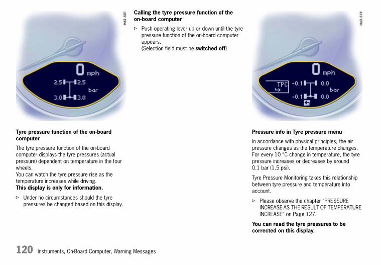
120 Instruments, On-Board Computer, Warning Messages
Tyre pressure function of the on-board computer
The tyre pressure function of the on-board computer displays the tyre pressures (actual pressure) dependent on temperature in the four wheels.You can watch the tyre pressure rise as the temperature increases while driving.This display is only for information.
f Under no circumstances should the tyre pressures be changed based on this display.
Calling the tyre pressure function of the on-board computer
f Push operating lever up or down until the tyre pressure function of the on-board computer appears.(Selection field must be switched off)
Pressure info in Tyre pressure menu
In accordance with physical principles, the air pressure changes as the temperature changes. For every 10 °C change in temperature, the tyre pressure increases or decreases by around 0.1 bar (1.5 psi).
Tyre Pressure Monitoring takes this relationship between tyre pressure and temperature into account.
f Please observe the chapter “PRESSURE INCREASE AS THE RESULT OF TEMPERATURE INCREASE” on Page 127.
You can read the tyre pressures to be corrected on this display.
10_Turbo_20.book Seite 120 Freitag, 7. August 2009 12:55 12

Instruments, On-Board Computer, Warning Messages 121
The tyre pressure to be corrected (refill pressure) is indicated on the displayed wheel.Example: If “–0.1 bar” (“–1.5 psi”) is displayed for the rear right tyre, 0.1 bar (1.5 psi) must be added to this tyre.
Note
The Tyre pressure menu can only be called up when the vehicle is stationary.
Calling up the “Info pressure” display
f Push operating lever forward in order to switch on the selection field.
f Select “TPM” with the operating lever.
f Push operating lever forward. The display changes to the Tyre pressure menu.
f Select “Info pressure” with the operating lever.
f Push operating lever forward.
Note
After the ignition is switched on, it can take up to approx. 1 minute before all tyre pressures are displayed. Dashes (“-.-”) appear instead of the tyre pressures.
Tyre type info in Tyre pressure menu
Information about the currently set tyres:
– Tyre type: Summer tyres, winter tyres
“Info tyres” shows the current tyre settings.
Calling up the “Info tyres” display
f Push operating lever forward in order to switch on the selection field.
f Select “TPM” with the operating lever.
f Push operating lever forward. The display changes to the Tyre pressure menu.
f Select “Info tyres” with the operating lever.
f Push operating lever forward.
Tyre selection in the “Set” menu
f Push operating lever forward in order to switch on the selection field.
f Select “TPM” with the operating lever.
10_Turbo_20.book Seite 121 Freitag, 7. August 2009 12:55 12

122 Instruments, On-Board Computer, Warning Messages
f Push operating lever forward. The display changes to the Tyre pressure menu.
f Select “Set” with the operating lever. f Push operating lever forward.
f Select desired tyre type: summer or winter.
f Push operating lever forward.A display for confirming the selected type of tyre appears.
10_Turbo_20.book Seite 122 Freitag, 7. August 2009 12:55 12

Instruments, On-Board Computer, Warning Messages 123
f Select “continue” and push the operating lever forward.
Tyre selection has only been successfully completed when the message “Process complete” is displayed by the on-board computer.
f Select arrow (Back) and push the operating lever forward. The display returns to the Tyre pressure menu. The on-board computer additionally displays the message “TPM is learning”.
Notes
The message “Process cancelled” appears if the setting process is interrupted. All entries made up to this point are lost, and the original settings remain in effect.
Only if the message “Process complete” appears after the settings have been made will the tyre pressure monitoring system re-learn the wheels.
f Please observe the chapter “SYSTEM LEARNING” on Page 126.
Before fitting tyres with sizes which are not stored in the on-board computer, the missing information should be supplemented in the on-board computer.
f Consult a qualified specialist workshop. We recommend a Porsche partner for this work as they have trained workshop personnel and the necessary parts and tools.
f Use only tyres approved by Porsche.
The available items in the Tyre pressure menu depend on the tyres on your vehicle. For this reason it is possible that some of the selection possibilities shown here are not available on your on-board computer’s display.
f Make sure that the tyre pressures correspond to the on-board computer settings. Correct the tyre pressures if necessary.
f Please observe the chapter “TYRE INFLATION PRESSURE FOR COLD TYRES (20 °C)” on Page 249.
10_Turbo_20.book Seite 123 Freitag, 7. August 2009 12:55 12

124 Instruments, On-Board Computer, Warning Messages
Load
f Push operating lever forward in order to switch on the selection field.
f Select “TPM” with the operating lever.
f Push operating lever forward. The display changes to the Tyre pressure menu.
f Select “Load” with the operating lever.
f Select partial load or full load and push the operating lever forward.
f Please observe the chapter “TYRE INFLATION PRESSURE FOR COLD TYRES (20 °C)” on Page 249.
f Make sure that the tyre pressures correspond to the on-board computer settings. Correct the tyre pressures if necessary.
Tyre pressure warnings
The tyre pressure warning light on the instrument panel and a corresponding message on the on-board computer warn about loss of pressure in two stages, depending on the amount of pressure loss.
Stage 1 – Add air
The pressure in the tyre is too low by 0.3 to 0.5 bar (4 to 7 psi). The tyre pressure warning contains the affected tyre with the tyre pressure to be added. Correct the tyre pressure at the next opportunity.
10_Turbo_20.book Seite 124 Freitag, 7. August 2009 12:55 12

Instruments, On-Board Computer, Warning Messages 125
This tyre pressure warning appears
– for approx. 10 seconds when the vehicle is stationary and the ignition is switched off or
– when the ignition is switched on again.
The warning can be acknowledged when the ignition is switched on.
The tyre pressure warning light on the instrument panel goes out when the tyre pressure has been corrected.
Stage 2 – Flat tyre
At speeds below 160 km/h (100 mph):
The pressure in the tyre has dropped by at least 0.5 bar (7 psi). This significant pressure loss is a danger to road safety.
At speeds above 160 km/h (100 mph):
The pressure in the tyre has dropped by at least 0.4 bar (6 psi). This significant pressure loss is a danger to road safety.
f When the tyre pressure warning appears, stop immediately at a suitable location. Check the indicated tyre for signs of damage. If necessary, fill in tyre sealant and set the correct tyre pressure.
This tyre pressure warning also appears when driving and can be acknowledged. The tyre pressure warning light on the instrument panel goes out only when the tyre pressure has been corrected.
10_Turbo_20.book Seite 125 Freitag, 7. August 2009 12:55 12

126 Instruments, On-Board Computer, Warning Messages
System learning
The tyre pressure monitoring system begins to “learn” the wheels after a wheel change, wheel transmitter replacement or update of the tyre settings. During this process, Tyre Pressure Monitoring recognises the wheels and their locations. The on-board computer displays the message “TPM is learning, monitoring not act.”.
Tyre Pressure Monitoring requires a certain amount of time to learn the wheels. During this time, the current tyre pressures are not available on the on-board-computer:
– The tyre pressure warning light remains lit until all wheels have been learned.
– The display of the Tyre pressure function of the on-board computer shows lines.
– The required pressures for cold tyres (20 °C) are indicated in the Info pressure display in the Tyre pressure menu.
Position and pressure information is displayed as soon as Tyre Pressure Monitoring has assigned the wheels recognised as belonging to the vehicle to the correct wheel positions.
The wheel learning process takes place exclusively when the vehicle is being driven (vehicle speed above 25 km/h (16 mph)).
f Check the tyre pressure for all wheels on the “Info pressure” display.
f Correct the tyre pressure to the required pressure if necessary.
Changing a wheel and replacing tyres
f New wheels must be fitted with radio transmitters for Tyre Pressure Monitoring. Before tyres are changed, the battery charge state of the wheel transmitters should be checked.Consult a qualified specialist workshop. We recommend a Porsche partner for this work as they have trained workshop personnel and the necessary parts and tools.
f Switch the ignition off when changing a wheel.
The tyre settings on the on-board computer must be updated after changing a wheel.If the tyre settings are not updated, the message “Wheel change? Input new TPM settings!” is displayed on the on-board computer.
f Update the on-board computer settings when the vehicle is stationary the next time.
The warning light in the speedometer lights up:
– when a loss in pressure has been detected,
– in the event of a defect in Tyre Pressure Monitoring or a temporary fault,
– when learning newly fitted wheels/wheel transmitters, as long as the vehicle's own wheels have not yet been recognised.
The tyre pressure warning light on the instrument panel goes out only when the cause of the fault has been rectified.
Partial monitoring
Monitoring of the other wheels is continued if there is a fault in one or two wheel transmitters.
– The tyre pressure warning light lights up.
– The message “TPM partial monitoring” is displayed on the on-board computer.
– No tyre pressures are displayed on the on-board computer for wheels with faulty wheel transmitters.
Warning light
10_Turbo_20.book Seite 126 Freitag, 7. August 2009 12:55 12

Instruments, On-Board Computer, Warning Messages 127
No monitoring
In the event of faults, Tyre Pressure Monitoring cannot monitor the tyre pressure. The warning light on the instrument panel lights up and a corresponding message appears on the on-board computer.
Monitoring is not active:
– if Tyre Pressure Monitoring is faulty,
– if wheel transmitters for Tyre Pressure Monitoring are missing,
– during the learning phase after the tyre settings have been updated,
– after a wheel change without updating the tyre settings,
– if more than four wheel transmitters are recognised,
– if there is external interference by other radio sources, e.g. wireless headphones,
– if tyre temperatures are too high.
f Please observe the chapter “WARNINGS ON THE INSTRUMENT PANEL AND THE ON-BOARD COMPUTER” on Page 134.
Pressure increase as the result of temperature increase
In accordance with physical principles, the air pressure changes as the temperature changes. For every 10 °C change in temperature, the tyre pressure increases or decreases by around 0.1 bar (1.5 psi).
Tyre Pressure Monitoring takes this relationship between tyre pressure and temperature into account.
Tyre pressure specifications
Information on tyre pressure for public roads can also be found in this Driver’s Manual or on the tyre-pressure plate in the left door aperture.These values apply to cold tyres at 20 °C.
f Only use the pressure specifications from the Info pressure display in the Tyre pressure menu or from the respective tyre pressure warning to correct the tyre pressure.
10_Turbo_20.book Seite 127 Freitag, 7. August 2009 12:55 12

128 Instruments, On-Board Computer, Warning Messages
OILDisplay and measurement of the engine oil level
d Caution!
Risk of engine damage.
f Regularly check the oil level each time before refuelling.
f Do not allow the oil level to fall below the minimum mark.
Conditions for measuring the oil level
1. Vehicle stationary.
2. Vehicle is level.
3. Engine must be at operating temperature (at least 60 °C).
4. Engine must be idling.
Failure
A failure of the oil level display is indicated by a warning message on the on-board computer.
Initiating oil level measurement
1. Push operating lever forward in order to switch on the selection field.
2. Select “OIL” with the operating lever.
3. Push operating lever forward. Measurement is started.
4. Allow waiting time to elapse.
5. Once the measurement has been completed, you can read off the engine oil level on the segment display.
10_Turbo_20.book Seite 128 Freitag, 7. August 2009 12:55 12

Instruments, On-Board Computer, Warning Messages 129
6. If the segments are filled in up to the top line, the oil level has reached the maximum mark. Under no circumstances add engine oil.
7. If the bottom segment is filled in, the oil level has reached the minimum mark.Add engine oil immediately.
8. If the bottom segment flashes, the oil level has dropped to below the minimum mark.Add engine oil immediately.
The difference between the minimum and maximum marks on the segment display is approx. 1.25 litres.One segment of the display corresponds to a top-up quantity of approx. 0.4 litres.
f Add engine oil if necessary. Switch off ignition before adding engine oil.Do not start engine when oil filler cap is open.
Please observe the chapter “ENGINE OIL LEVEL” on Page 182.
f Never add more engine oil than required to reach the maximum mark.
Failure
A failure of the oil level display is indicated by a warning message on the on-board computer.
“Check engine oil level” display
The on-board computer display “Check engine oil level” is an additional measurement that takes place in the background while driving.
The display depends on the distance travelled. This display appears if the oil level has dropped below the minimum mark or if the oil level is well above the maximum mark.
This message must be acknowledged by measuring the engine oil level manually using the on-board computer.
f Please observe the chapter “INITIATING OIL LEVEL MEASUREMENT” on Page 128.
If oil level measurement was initiated manually on the on-board computer and no oil was added, the message “Check engine oil level” is displayed again. This message depends on the distance travelled.
10_Turbo_20.book Seite 129 Freitag, 7. August 2009 12:55 12

130 Instruments, On-Board Computer, Warning Messages
SETBasic setting of on-board computer
Switching on selection field “D”
f Push operating lever forward.
Changing the basic setting of the on-board computer
f Select “SET” with the operating lever.
f Push operating lever forward.
f Select the desired function with the operating lever:
Reset
– Reset all,Reset average consumption,Reset average speed,Reset trip counter
Units
– Speedometer:km – km/h, miles – mph
– Consumption:l/100 km, mls/gal (USA), mpg (UK), km/l
10_Turbo_20.book Seite 130 Freitag, 7. August 2009 12:55 12

Instruments, On-Board Computer, Warning Messages 131
– Temperature:°Celsius, °Fahrenheit
– Tyre pressure: bar, psi
Oil pressure(Select central line of the on-board computer)
– Change displayAudio information (set radio station),Remain. range,Empty
– Telephone infoWhen Telephone information is active, incoming telephone calls are displayed on the on-board computer.
Navigation
– Integrated in the on-board computer(navigation instructions can be called on the on-board computer display)
– When turning(navigation instructions are displayed only prior to direction changes)
Basic setting
– Restore the basic setting of the on-board computer
Language
– Select language version
Clock 12/24h mode
– Select time mode:12h (small squares on the right side of the time display for AM/PM),24h
Light
Switch daytime driving lights on and off.
f Please observe the chapter “DAYTIME DRIVING LIGHTS” on Page 63.
Daytime driving lights (daytime driving lights switched off)
Daytime driving lights (daytime driving lights switched on)
10_Turbo_20.book Seite 131 Freitag, 7. August 2009 12:55 12

132 Instruments, On-Board Computer, Warning Messages
General information regarding the on-board computer functions
Remaining range
The remaining range is continuously recalculated during the journey based on the fuel level, current consumption and average consumption.The more the fuel level falls, the more spontaneously the display reacts. For this reason, the range on remaining fuel is not displayed if it is less than 15 kilometres (9 miles).
If the vehicle’s inclination changes while driving or refuelling, incorrect range information may temporarily be given.
Note
If the tank is nearly empty and you top up with only a small quantity of fuel, this cannot be used to calculate the range on remaining fuel.
Average consumption and average speed
The displayed values are based on the distance travelled since the last reset to “zero”.
You can set the starting time for a measurement before or during the trip.Switching the ignition off does not reset the measurements. Values can thus be collected over long periods.Disconnecting the car battery will cause these memories to be erased.
Tyre pressure
The Tyre pressure function of the on-board computer displays the tyre pressures dependent on temperature in the four wheels. You can watch the tyre pressure rise and fall while driving.The display is only for information. To correct the tyre pressures, always use the displayed values from the “Info pressure” display in the Tyre pressure menu.
10_Turbo_20.book Seite 132 Freitag, 7. August 2009 12:55 12

Instruments, On-Board Computer, Warning Messages 133
Engine boost pressure
The engine boost pressure is regulated by the engine control unit. The maximum boost pressure is approx. 1 bar (14.5 psi). It is, however, greatly dependent on the ambient air pressure and the fuel grade.
f Please observe the chapter “SPORT MODE” on Page 51.
10_Turbo_20.book Seite 133 Freitag, 7. August 2009 12:55 12

134 Instruments, On-Board Computer, Warning Messages
Warnings on the instrument panel and the on-board computer
If a warning message appears, always refer to the corresponding chapters in the Driver’s Manual.Warning messages are issued only if all measurement preconditions are met. Therefore, check all fluid levels regularly – in particular, always check the engine oil level before refuelling.
Acknowledging warning messages
Warning messages can be deleted from the on-board computer display.
f Push the on-board computer operating lever forward.
You can recall erased warning messages in the “INFO” menu.
*We recommend a Porsche partner for this work as they have trained workshop personnel and the necessary parts and tools.
Instrument panel
On-board computer
Text display on on-board computer
Meaning/measure
Seat belt Driver and passengers must fasten their seat belts.
Handbrake Handbrake is still on.
Ignition key not removed
Replace battery in ignition key
Replace the remote-control battery.
Ignition lock faulty. Visit workshop
Consult a qualified specialist workshop.*
Ignition lock faulty. Visit workshop now
Consult a qualified specialist workshop.*
Relievesteering
Relieve the steering lock by moving the steering wheel to the left or right.
10_Turbo_20.book Seite 134 Freitag, 7. August 2009 12:55 12

Instruments, On-Board Computer, Warning Messages 135
Steering locked The steering wheel lock remains engaged. Have the fault remedied at a qualified specialist workshop.*
Lights on
Dipped beam/side light on.
Parking light on
Left/right parking light on.
Checkleft/right dippedbeam
also applies to: Direction indicator light, high beam headlight, side indicator light, reversing light.
The reported light is faulty. Check corresponding bulb.Consult a qualified specialist workshop.*
Daytime driving lightsoff
Daytime driving lights switch off when the engine is shut off.
Headlight beamadjustmentfaulty
Consult a qualified specialist workshop.*
Front lidnotclosed
Close luggage compartment lid properly.
Rear lidnotclosed
Close engine compartment lid properly.
Rain sensorfaulty
Consult a qualified specialist workshop.*
Steering wheel heatingON
Steering wheel heating was switched on.
Instrument panel
On-board computer
Text display on on-board computer
Meaning/measure
10_Turbo_20.book Seite 135 Freitag, 7. August 2009 12:55 12

136 Instruments, On-Board Computer, Warning Messages
Steering wheel heatingoff
Steering wheel heating was switched off.
Drive-Off Assistantfailure
Consult a qualified specialist workshop.*
Refill washer fluid
LIMITCannot beaccepted with vehicle stopped
The current speed can only be accepted for the acoustic warning signal when the vehicle is in motion.
LIMIT50
Selected speed limit (e.g. 50 km/h (30 mph)) for the acoustic warning signal has been exceeded. Adjust your speed if necessary.
Warning light Fuelgauge
Considerremaining range
Refuel at the next opportunity.
Check engine oil level Start engine oil level measurement in the on-board computer.
Oil pressure too low
Stop immediately in a suitable place,measure oil level with the on-board computer,and, if necessary, add engine oil.
Warning light for temperature gauge
Enginetemperaturetoo high
Switch engine off and let it cool.Check coolant level and, if necessary,add coolant.
Temperature gauge warning light flashes
Checkcoolant level
Switch off engine and let it cool down.Check coolant level and, if necessary, add coolant.
Check Engine,Visit workshop
Consult a qualified specialist workshop.*
Instrument panel
On-board computer
Text display on on-board computer
Meaning/measure
10_Turbo_20.book Seite 136 Freitag, 7. August 2009 12:55 12

Instruments, On-Board Computer, Warning Messages 137
Reducedenginepower
Consult a qualified specialist workshop.*
Temperature gauge warning light flashes
Failure of engine comp. blower
Consult a qualified specialist workshop.*
Warning Battery/generator
Stop at a safe place and switch the engine off. Do not continue driving.Have the fault remedied at a qualified specialist workshop.*
Failure oil level indicator
Consult a qualified specialist workshop.*
FailureOil level faulty
Consult a qualified specialist workshop.*
Oil temp.indicator faulty
Consult a qualified specialist workshop.*
Failure indicator Coolant indicator failed.Consult a qualified specialist workshop.*
Service wear onbrake pads
Have the brake pads changed immediately.Consult a qualified specialist workshop.*
Brake fluid levelwarning
Stop immediately in a suitable place.Do not continue driving. Have the fault remedied by a qualified specialist workshop.*
Brake distributionwarning
Stop immediately in a suitable place.Do not continue driving. Have the fault remedied by a qualified specialist workshop.*
ABS failure Consult a qualified specialist workshop.*
Instrument panel
On-board computer
Text display on on-board computer
Meaning/measure
10_Turbo_20.book Seite 137 Freitag, 7. August 2009 12:55 12

138 Instruments, On-Board Computer, Warning Messages
PSMoff
Porsche Stability Management was switched off.
PSMon
Porsche Stability Management was switched on.
PSM failure Consult a qualified specialist workshop.*
PSMinitialisation
f Please observe the chapter “PUTTING VEHICLE INTO OPERATION” on Page 225.
PASMNormal/Sport
Indicator for selected PASM mode
PASM failure Consult a qualified specialist workshop.*
PASMindicatorfaulty
Consult a qualified specialist workshop.*
FailureSport mode
Consult a qualified specialist workshop.*
PADM failure Dynamic Engine Mounting failure.Consult a qualified specialist workshop.*
System faultAirbag
Airbag is faulty.Consult a qualified specialist workshop.*
FailureSpoilercontrol
Driving stability is impaired.Adjust your driving style.Consult a qualified specialist workshop.*
Instrument panel
On-board computer
Text display on on-board computer
Meaning/measure
10_Turbo_20.book Seite 138 Freitag, 7. August 2009 12:55 12

Instruments, On-Board Computer, Warning Messages 139
Selector lever position display flashes
Selector lever not engaged
PDK transmission:Selector lever can be between two positions. Engage selector lever correctly.
Move selectorlever toP
PDK transmission: Move selector lever to position P before withdrawing key from ignition lock.
Applybrake
PDK transmission:Apply the brake when starting.
Depress clutch pedal
Manual transmission:press clutch pedal when starting.
Move selector lever toP or N
PDK transmission:The vehicle can only be started in selector lever position P or N.
Text display in white:
Transmission emergency run
Restricted gearshift comfort,reverse gear fails.
Have the fault repaired immediately. Consult a qualified specialist workshop.*
Text display in red:
Transmission emergency run
No selector lever position is displayed on the instrument cluster.Vehicle can only be driven until it comes to a stop.
It is not possible to continue driving. Stop the vehicle immediately in a suitable place. Have the vehicle towed to a qualified specialist workshop.
Instrument panel
On-board computer
Text display on on-board computer
Meaning/measure
10_Turbo_20.book Seite 139 Freitag, 7. August 2009 12:55 12

140 Instruments, On-Board Computer, Warning Messages
Transmissiontemperaturetoo high
“Warning jerks” can be felt when driving off and the engine power may be restricted.
Do not hold the vehicle with the accelerator on a hill, for example. Hold the vehicle with the brake. Reduce engine load. Stop the vehicle in a suitable place if possible. Allow the engine to run in selector lever position P or N until the warning disappears.
Flat tyre! Tyre Pressure Monitoring has detected a serious pressure loss.Stop in a suitable place and check the tyres for damage. Fill in tyre sealant as necessary.
Add air Tyre Pressure Monitoring has detected a gradual pressure loss. Correct tyre pressure at the next opportunity.
TPM is learning,monitoringnot active
Tyre Pressure Monitoring is learning the wheels on the vehicle. Tyre Pressure Monitoring is searching for the tyres and their position. During this period the current pressure values are not available on the on-board computer.
TPM inactive Tyre Pressure Monitoring is faulty.Consult a qualified specialist workshop.*
TPM partial monitoring 1 or 2 wheel transmitters are faulty. The tyre pressures of these wheels are not monitored.The other wheels are still monitored.Consult a qualified specialist workshop.*
Instrument panel
On-board computer
Text display on on-board computer
Meaning/measure
10_Turbo_20.book Seite 140 Freitag, 7. August 2009 12:55 12

Instruments, On-Board Computer, Warning Messages 141
TPM inactiveBriefdisturbance
TPM inactivetoo manywh. transm.
Tyre Pressure Monitoring is temporarily deactivated by excessive tyre temperatures (circa 120 °C) or external interference (e.g. from other wheel transmitters inside the car). Once the source of the interference is removed, the system is automatically reactivated.
Wheel change?Input newTPM settings!
Update the settings in the TPM menu of the on-board computer at the next opportunity. Wrong entries will affect the correct pressure information in the menu. The safety of your vehicle is at risk.
TPMindicatorfailure
The display of Tyre Pressure Monitoring is faulty.Consult a qualified specialist workshop.*
System faultVisit workshop
Several systems may have failed. Adjust your driving style.Consult a qualified specialist workshop.*
Failure in Fuel level indicatorWorkshop
Consult a qualified specialist workshop.*
Service in km/days Service indicatorBring the vehicle in for service no later than after the distance/time shown has elapsed. However, it is the intervals in the “Guarantee and Maintenance” booklet that are decisive.
Service now Service indicatorHave your vehicle serviced at a qualified specialist workshop.*
Instrument panel
On-board computer
Text display on on-board computer
Meaning/measure
10_Turbo_20.book Seite 141 Freitag, 7. August 2009 12:55 12
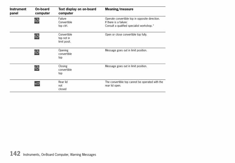
142 Instruments, On-Board Computer, Warning Messages
FailureConvertibletop ctrl.
Operate convertible top in opposite direction.If there is a failure:Consult a qualified specialist workshop.*
Convertibletop not inlimit posit.
Open or close convertible top fully.
Openingconvertibletop
Message goes out in limit position.
Closingconvertibletop
Message goes out in limit position.
Rear lidnotclosed
The convertible top cannot be operated with the rear lid open.
Instrument panel
On-board computer
Text display on on-board computer
Meaning/measure
10_Turbo_20.book Seite 142 Freitag, 7. August 2009 12:55 12

Shifting Gears 143
Shifting gearsManual Transmission, Clutch ....................... 144Drive-Off Assistant...................................... 145Porsche Doppelkupplung Transmission (PDK) ........................................................ 146
10_Turbo_20.book Seite 143 Freitag, 7. August 2009 12:55 12

144 Shifting Gears
Manual Transmission, Clutch
d Warning!
Risk of accident.
f Do not obstruct the pedal travel with floor mats or other objects.Non-skid floor mats of the correct size are available at your Porsche partner.
The positions of the gears are shown on the shift diagram on the gearshift lever.
f When shifting gears, always ensure that the clutch pedal is fully depressed and the gear has fully engaged.
f Select reverse only when vehicle is stationary.Reverse gear can be engaged after shifting the gearshift lever as far as possible to the left.
f Select an appropriately low gear on upward and downward slopes. This will ensure optimum use of engine power and engine braking.
When reverse gear is selected and the ignition is on, the reversing lights are lit.
Permitted engine speed
f You should change into a higher gear before the needle reaches the red mark on the tachometer, or ease off the accelerator.
If the maximum permitted engine speed is reached during acceleration, fuel feed is interrupted.
d Caution!
Risk of engine damage (overrevving) when shifting down to a lower gear.
f Take care not to exceed the maximum permitted engine speed when shifting down.
10_Turbo_20.book Seite 144 Freitag, 7. August 2009 12:55 12

Shifting Gears 145
Drive-Off AssistantThe Drive-Off Assistant assists the driver when moving off on hills. The vehicle must have sufficient road contact.
The Drive-Off Assistant is available on gradients of around 5 % or higher.
d Danger!
Risk of accidents. Assistance by the Drive-Off Assistant is not guaranteed when moving off on a slippery surface (e.g. on icy or loose surfaces). In this case, the vehicle could slip. The limits set by the physics of driving cannot be overcome, even with the Drive-Off Assistant. Ultimately, the driver is still responsible for moving off on upward slopes, despite the Drive-Off Assistant.
f Always adjust your driving style to the driving conditions and vehicle load, use the footbrake if necessary.
Risk of accidents. If the Drive-Off Assistant is not functioning, the driver cannot be assisted when moving off on hills.
f Hold the vehicle using the handbrake.
Driving off with the Drive-Off Assistant(vehicles with manual transmission)
1. Hold the vehicle securely on the slope with the footbrake. The engine must be running.
2. Fully depress the clutch pedal.
3. Engage a gear corresponding to the direction of travel up the slope (1st gear or reverse gear).
4. Fully release the handbrake.
5. Release the footbrake while keeping the clutch pedal pressed.The vehicle is held on the slope for a short time to facilitate driving off immediately after the brake is released.
6. Move off as usual.
Note on operation
The Drive-Off Assistant is not active:
– if the clutch is not depressed,
– if the vehicle is not stationary,
– if the engine is not running,
– on gradients of less than 5 %,
– if there is not enough pressure on the brake pedal.
Driving off with the Drive-Off Assistant(vehicles with PDK transmission)
1. Hold the vehicle securely on the slope with the footbrake. The engine must be running.
2. Select a gear corresponding to the direction of travel up the slope (selector lever position D or R).
3. Fully release the handbrake.
4. Release the footbrake.The vehicle is held on the slope for a short time to facilitate driving off immediately after the brake is released.
5. Move off as usual.
Note on operation
The Drive-Off Assistant is not active:
– if you shift to neutral.
– if the vehicle is not stationary.
– if the engine is not running.
– on gradients of less than 5 %.
– if there is not enough pressure on the brake pedal.
10_Turbo_20.book Seite 145 Freitag, 7. August 2009 12:55 12
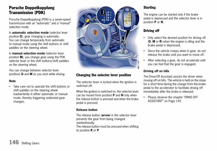
146 Shifting Gears
Porsche Doppelkupplung Transmission (PDK)Porsche Doppelkupplung (PDK) is a seven-speed transmission with an “automatic” and a “manual” selection mode.
In automatic selection mode (selector lever position D), gear changing is automatic.You can change temporarily from automatic to manual mode using the shift buttons or shift paddles on the steering wheel.
In manual selection mode (selector lever position M), you change gear using the PDK selector lever or the shift buttons/shift paddles on the steering wheel.
You can change between selector lever positions D and M as you wish while driving.
Note
f Take care not to operate the shift buttons or shift paddles on the steering wheel inadvertently in either automatic or manual mode, thereby triggering undesired gear changes.
Changing the selector lever position
The selector lever is locked when the ignition is switched off.
When the ignition is switched on, the selector lever can be moved from position P and N only when the release button is pressed and when the brake pedal is pressed.
Release button
The release button (arrow) in the selector lever prevents the gear from being changed unintentionally.The release button must be pressed when shifting to position R or P.
Starting
The engine can be started only if the brake pedal is depressed and the selector lever is in position P or N.
Driving off
f Only select the desired position for driving off (D, M or R) when the engine is idling and the brake pedal is depressed.
f Since the vehicle creeps when in gear, do not release the brake until you want to move off.
f After selecting a gear, do not accelerate until you can feel that the gear is engaged.
Driving off on hills
The Drive-Off Assistant assists the driver when moving off on hills. The vehicle is held on the slope for a short time during the change from the brake pedal to the accelerator to facilitate driving off immediately after the brake is released.
f Please observe the chapter “DRIVE-OFF ASSISTANT” on Page 145.
10_Turbo_20.book Seite 146 Freitag, 7. August 2009 12:55 12

Shifting Gears 147
Indicator for selector-lever position and engaged gear
When the engine is running, the selector lever position and engaged gear are indicated.
If the selector lever is between two positions
– Effects:The corresponding selector-lever position in the instrument cluster flashes and the warning “Actuate brake” or “Selector lever not engaged” appears on the on-board computer.
f Action required:Operate the footbrake and properly engage the selector lever.
If the selector lever is inadvertently (due to a defect or incorrect operation) moved out of P or N into gear without pressing the brake, this gear will start to "flash" and no power transmission is built up.
f To drive off, press the brake and move the selector lever from P or N into the required gear again.
Selector-lever position R or D is flashing in the instrument cluster
– Effects:There is no power transmission.The selector lever was engaged without pressing the footbrake or only the restricted driving programme is available when the “Transmission emergency run” message is displayed.
f Action required:Press the footbrake and engage the required selector-lever position again by moving the selector lever from P or N.If reverse gear fails:
f Please observe the chapter “REDUCED DRIVING PROGRAMME” on Page 152.
If there is a fault in the transmission:
– The warning “Transmission emergency run” in white or red lettering or the warning “Transmission temperature too high” is displayed on the on-board computer.Please observe the chapter “REDUCED DRIVING PROGRAMME” on Page 152.
f Have the fault repaired immediately.Consult a qualified specialist workshop. We recommend a Porsche partner for this work as they have trained workshop personnel and the necessary parts and tools.
10_Turbo_20.book Seite 147 Freitag, 7. August 2009 12:55 12

148 Shifting Gears
Selector-Lever Positions
P – Parking lock
f Engage parking lock only when vehicle is stationary.If selector-lever position P is flashing in the instrument cluster, the parking brake is not engaged. The vehicle can roll away.Engage selector-lever position P again by moving the selector lever out of R.
f Engage parking lock after applying the handbrake and release it before releasing the handbrake.
The ignition key can be withdrawn only in selector lever position P.
R – Reverse gear
f Select only if car is stationary and the brake is applied.
N – Neutral
Selector lever position N must be selected for towing or in car washes, for example.
f Only select the desired position for driving off (D, M or R) when the engine is idling and the brake pedal is depressed.
D – Automatic selection mode
Select position D for “normal” driving. The gears are shifted automatically according to the accelerator position and speed.
Depending on the way the vehicle is driven (economical, comfortable or sporty driving style) and on the resistance (e.g. uphill), the gear-changing points are shifted towards higher or lower engine-speed ranges.The accelerator position, driving speed, engine speed, longitudinal and lateral acceleration and the road profile all have an influence on the gear-changing characteristic.
Unwanted upward shifts, e.g. before bends, are prevented by swiftly releasing the accelerator pedal.
Depending on lateral acceleration, upward changes on bends are not made until the engine-speed limit is reached.
During braking, and depending on the amount of deceleration, the PDK transmission changes down earlier.For subsequent cornering, the right gear is engaged when pressure is applied to the brakes before the bend. The bend is taken in the right gear, and when you accelerate out of the bend you do not have to change down.
With a sporty driving style, downshifts are already initiated when the brake pedal is touched lightly. This further enhances a dynamic driving style.The PDK transmission temporarily changes to the
sportiest gear-changing map, i.e. to the highest possible gear-changing points, if the accelerator pedal is pressed quickly. The transmission accordingly shifts down immediately by one or two gears (temporary change-down).
The transmission no longer automatically selects 7th gear at extremely high driving speeds. If necessary, the gear can however be selected manually.
Sport mode (“Sport” and “Sport Plus” mode)
“Sport” mode activated:The PDK transmission switches to a sporty gear-changing map and shortens the gear shifting times.A sporty driving style is recognised more quickly and the gear-changing speeds are adapted to driving performance.
Deceleration downshifts are initiated earlier. Downshifts are already carried out in the case of slight decelerations, even at higher engine speeds.
“Sport Plus” mode activated:In “Sport Plus” mode, the PDK transmission changes to a shift program designed for driving on race circuits. 7th gear is not selected.The gear-changing performance is enhanced significantly again compared with “Sport” mode.
f Please observe the chapter “SPORT MODE” on Page 47.
10_Turbo_20.book Seite 148 Freitag, 7. August 2009 12:55 12

Shifting Gears 149
Driving off with Launch Control
Launch Control allows you to achieve maximum acceleration from stationary.
d Warning!
There is a risk of endangering other road users.Stress on components increases dramatically when starting with maximum acceleration in comparison with “normal” driving off.
f Launch Control should preferably be used on race circuits.
f Only use Launch Control if road and traffic conditions permit.
f Do not endanger other road users or cause a nuisance when using Launch Control.
Conditions:
– Launch Control should only be used when the engine has reached operating temperature.
– “Sport Plus” mode must be switched on (light-emitting diode in button is on and “SPORT PLUS” is displayed on the steering wheel).
1. Press the brake with your left foot.
2. Quickly press the accelerator down fully (kickdown activated) and hold it.The engine speed will level off at around 5000 rpm.“Launch Control active” appears on the steering-wheel display.
3. Release the brake within a few seconds.
Remaining stationary for a long time with “Launch Control active” can lead to overloading of the transmission.To protect the transmission, the engine power is then reduced and the “Launch Control active” process is cancelled.
Shifting gears on the steering wheel
With the rocker switches on the steering wheel, you can change temporarily from automatic selection mode D to manual mode M.
For example:
– Shifting down before bends and on entering built-up areas.
– Shifting down on downward slopes (engine braking).
– Shifting down for brief spurts of acceleration.
Manual selection mode remains engaged:
– for cornering (depending on the lateral acceleration) and overrunning,
– when the vehicle is stationary (e.g. at a junction).
The system leaves manual selection mode:
– automatically after approx. 8 seconds (unless cornering or overrunning),
– after driving off.
Kickdown
The kickdown function is active in selector lever positions D and M.
f For optimum acceleration, e.g. when overtaking, depress the accelerator pedal beyond the full-throttle point (kickdown).
The transmission shifts down depending on the speed of travel and engine speed.Upward shifts occur at the highest possible engine speeds.
10_Turbo_20.book Seite 149 Freitag, 7. August 2009 12:55 12

150 Shifting Gears
M – Manual selection mode
The currently selected gear is retained when you change from D to M.
If you change from M to D, the gear-changing map suitable for your current driving style is selected and the appropriate gear is selected.
The selector lever and the two shift buttons in the upper steering-wheel spokes or the two shift paddles allow you to comfortably and reliably select the seven forward gears.
Shift buttonsA - Sport/Sport Plus displayB - Launch Control display
+ Shifting up using selector lever or shift buttons
f Press PDK selector lever or shift button on the steering wheel forward..
– Shifting down using selector lever or shift buttons
f Pull PDK selector lever or shift button on the steering wheel back.
+ Shift up shift paddle- Shift down shift paddleA - Sport/Sport Plus displayB - Launch Control display
Shifting up using selector lever or right + shift paddle
f Pull PDK selector lever forward or push right shift paddle on the steering wheel back.
Shifting down using selector lever or left – shift paddle
f Pull PDK selector lever or left shift paddle on the steering wheel back.
10_Turbo_20.book Seite 150 Freitag, 7. August 2009 12:55 12

Shifting Gears 151
You can shift up or down by the corresponding number of gears by quickly operating the selector lever, the shift buttons or the shift paddles several times in succession.
The transmission can be shifted up or down by several gears in succession by continuously operating the selector lever, shift buttons or shift paddles.
Depending on driving speed and engine speed, you can shift up or down at any time.
Gear changes which would exceed the upper or lower engine-speed limit are not executed by the control unit.
There is no automatic upshift at the upper engine-speed limit in selector lever position M. Upshift suppression can be cancelled by kickdown operation. If, for example, the engine speed limit is reached during overtaking and an automatic upshift does not occur, the transmission in this case shifts up as a result of kickdown operation.
f Select an appropriately low gear on upward and downward slopes.This will ensure optimum use of engine power and engine braking.
To shift up automatically at the upper engine-speed limit:
f Depress the accelerator pedal beyond the full-throttle point (kickdown).
Stopping
f For a brief stop (e.g. at a traffic light), leave the selector lever in drive position and hold the vehicle with the brake pedal.
f Do not hold the car on a slope using the accelerator. Use the brake pedal or the handbrake instead.
f Before leaving the vehicle, always apply the handbrake and move the selector lever to position P.
Parking
f Go easy on the accelerator!
f When parking or manoeuvring in restricted space, control the speed by careful use of the footbrake.
Driving in winter
In wintry road conditions it is advisable to take steep inclines in manual mode. This prevents gear changes occurring that could cause wheelspin.
Tow-starting, towing
f Please observe the chapter “TOWING AND TOW-STARTING” on Page 241.
10_Turbo_20.book Seite 151 Freitag, 7. August 2009 12:55 12

152 Shifting Gears
Reduced driving programme
Failure of the selector lever display on the instrument cluster
The warning “Transmission emergency run” is displayed in red on the on-board computer.
– Effect: No selector lever position is displayed on the instrument cluster.Vehicle can only be driven until it comes to a stop. Action required:It is not possible to continue driving. Stop the vehicle immediately in a suitable place. Have the vehicle towed to a qualified specialist workshop.
f Please observe the chapter “TOWING AND TOW-STARTING” on Page 241.
If there is a fault in the transmission
– Depending on priority, the warning “Transmission emergency run” in white or red lettering or the warning “Transmission temperature too high” is displayed on the on-board computer.
Warning “Transmission emergency run” white
– Effects: Restricted gearshift comfort,reverse gear may not function.
Action required:Have the fault remedied immediately. Consult a qualified specialist workshop. We recommend a Porsche partner for this work as they have trained workshop personnel and the necessary parts and tools.
Warning “Transmission emergency run” red
– Effect: Vehicle can only be driven until it comes to a stop. Action required:It is not possible to continue driving. Stop the vehicle immediately in a suitable place. Have the vehicle towed to a qualified specialist workshop.
Warning “Transmission temperature too high”
– Effects:“Warning jerks” can be felt when driving off and the engine power may be restricted.Action required:Do not hold the vehicle with the accelerator on a hill, for example. Hold the vehicle with the brake. Reduce engine load. Stop the vehicle in a suitable place if possible. Allow the engine to run in selector lever position P or N until the warning disappears.
10_Turbo_20.book Seite 152 Freitag, 7. August 2009 12:55 12

Mobile Roofs 153
Mobile RoofsSliding/Lifting roof...................................... 154Convertible Top.......................................... 158Windstop ................................................... 168Hardtop..................................................... 172Roof Transport System............................... 178
10_Turbo_20.book Seite 153 Freitag, 7. August 2009 12:55 12

154 Mobile Roofs
Sliding/Lifting roof
d Warning!
Risk of injury when operating or automatically closing the sliding/lifting roof.
f Take care to ensure that nobody can be injured when the sliding/lifting roof is operated.
f Always withdraw the ignition key when leaving the vehicle. Uninformed persons (children) could injure themselves by operating the sliding/lifting roof.
f In case of danger, release the switch immediately and operate the sliding/lifting roof in the opposite direction.
Readiness for operation
– With the ignition switched on(engine on or off) or
– With door closed and ignition key withdrawn, but only until door is first opened.
A – Opening the sliding/lifting roof
f Press rear of rocker switch A until sliding/lifting roof reaches the desired position.
One-touch operation
f Briefly press rear of rocker switch A.Sliding/lifting roof opens to final position.Stop it in any position by touching any button.
Note
The sliding/lifting roof opens until it reaches the best position from the point of view of noise. It can be opened fully, however, if you press the rocker switch again.
10_Turbo_20.book Seite 154 Freitag, 7. August 2009 12:55 12

Mobile Roofs 155
B – Closing the sliding/lifting roof
f Press front of rocker switch B until the sliding/lifting roof has reached the desired position.
One-touch operation
f Touch front of rocker switch B.Sliding/lifting roof closes to final position.Stop it in any position by touching any button.
C – Lifting sliding/lifting roof
f Press centre of rocker switch C until sliding/lifting roof reaches the desired position.
One-touch operation
f Touch the rocker switch C in the centre.Sliding/lifting roof opens to final position. Touch switch again to stop in any position.
B – Lowering the sliding/lifting roof
f Press front of rocker switch B until sliding/lifting roof reaches the desired position.
10_Turbo_20.book Seite 155 Freitag, 7. August 2009 12:55 12
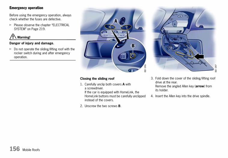
156 Mobile Roofs
Emergency operation
Before using the emergency operation, always check whether the fuses are defective.
f Please observe the chapter “ELECTRICAL SYSTEM” on Page 219.
d Warning!
Danger of injury and damage.
f Do not operate the sliding/lifting roof with the rocker switch during and after emergency operation.
Closing the sliding roof
1. Carefully unclip both covers A with a screwdriver.If the car is equipped with HomeLink, the HomeLink buttons must be carefully unclipped instead of the covers.
2. Unscrew the two screws B.
3. Fold down the cover of the sliding/lifting roof drive at the rear.Remove the angled Allen key (arrow) from its holder.
4. Insert the Allen key into the drive spindle.
10_Turbo_20.book Seite 156 Freitag, 7. August 2009 12:55 12
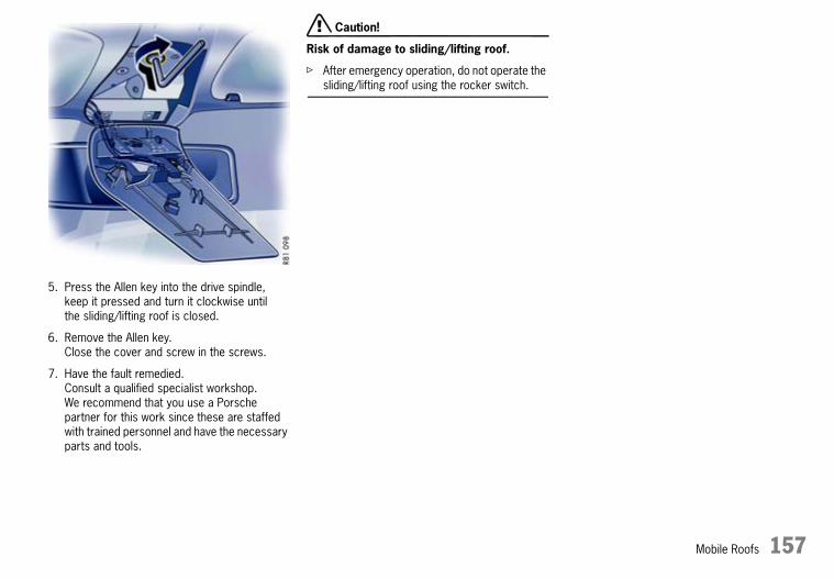
Mobile Roofs 157
5. Press the Allen key into the drive spindle, keep it pressed and turn it clockwise until the sliding/lifting roof is closed.
6. Remove the Allen key.Close the cover and screw in the screws.
7. Have the fault remedied. Consult a qualified specialist workshop. We recommend that you use a Porsche partner for this work since these are staffed with trained personnel and have the necessary parts and tools.
d Caution!
Risk of damage to sliding/lifting roof.
f After emergency operation, do not operate the sliding/lifting roof using the rocker switch.
10_Turbo_20.book Seite 157 Freitag, 7. August 2009 12:55 12

158 Mobile Roofs
Convertible TopBrief operating instructions can be found on the back of the driver’s sun visor.
f Please observe the chapter “CAR CARE INSTRUCTIONS” on Page 192.
d Safety notes!
Do not operate convertible top:
f At temperatures below 0 °C.
f When one side of the car is on a kerb, a lifting platform or a jack.
f When items of luggage or other objects hinder the movement of the convertible top.
f With the roll-over bars extended.
f Avoid frequent operation of the convertible top with the engine off; the vehicle battery will rapidly discharge.
f Only drive with the convertible top fully open or closed (end positions).
f When opening or closing the convertible top, ensure there is sufficient clearance above (e.g. in the garage).
f To prevent damp stains and abrasion damage, open the convertible top only when it is in a dry, clean state.
f Park car in the shade if possible, since continuous exposure to the sun attacks textiles, rubber and colours.
f The convertible top may only be operated when driving on a level surface.
f The convertible top must not be operated in strong head winds (over approx. 80 km/h or 50 mph).
Door windows and side windows
The side windows are lowered automatically when the convertible top is opened. The door windows close automatically if operation of the convertible top is continued after it has reached its final position.When the door windows are closed, the rear side windows can also be closed.The rear side windows open automatically when the door windows are opened.
The side windows are lowered automatically when the convertible top is closed. All windows close automatically if operation of the convertible top is continued after it has reached its final position.
Conditions for operating the convertible top
With the switch
– The ignition must be switched on (engine running or switched off),
– The engine compartment lid must be closed,
– Maximum speed up to approx. 50 km/h (30 mph).Opening/closing of the convertible top will be interrupted if the maximum speed is exceeded.
With the remote control
– The engine compartment lid must be closed.
10_Turbo_20.book Seite 158 Freitag, 7. August 2009 12:55 12

Mobile Roofs 159
Opening the convertible top
d Warning!
Danger of injury and damage.
f When opening the convertible top, make sure that nobody is at risk of injury from the convertible-top mechanism or the lid of the convertible-top compartment.
f Before opening the convertible top, ensure that there are no objects in the area behind the rear seats.
f Do not operate the convertible top with the remote control if the vehicle is out of your sight.
f In order to interrupt convertible-top operation in the event of danger, immediately release the switch or remote control.
f Please observe the chapter “WARNINGS ON THE INSTRUMENT PANEL AND THE ON-BOARD COMPUTER” on Page 134.
Opening convertible top with the switch
f Pull and hold the switch until the convertible top has reached its final position or until the door windows are in their desired position.The message on the on-board computer goes out.In case of danger, release the switch. Convertible top operation stops.
Opening convertible top with remote control(depending on country-specific vehicle equipment)
f Unlock the vehicle.Keep the convertible-top button on the remote control depressed until the convertible top has reached its final position or until the door windows are in the desired position.In case of danger, release the button. Convertible top operation stops.
f Re-lock the vehicle if necessary.
10_Turbo_20.book Seite 159 Freitag, 7. August 2009 12:55 12

160 Mobile Roofs
Closing the convertible top
d Warning!
Danger of injury and damage.
f When closing the convertible top, make sure that nobody is at risk from injury from the convertible-top mechanism or the convertible-top compartment lid.
f Do not operate the convertible top with the remote control if the vehicle is out of your sight.
f In order to interrupt convertible-top operation in the event of danger, immediately release the switch or remote control.
f Keep the lids of the make-up mirrors in the sun visors closed when closing the convertible top.
f Please observe the chapter “WARNINGS ON THE INSTRUMENT PANEL AND THE ON-BOARD COMPUTER” on Page 134.
Closing convertible top with the switch
f Pull and hold the switch until the convertible top has reached its final position or until the windows are in their desired position.The message on the on-board computer goes out.In case of danger, release the switch. Convertible top operation stops.
Closing convertible top with remote control(depending on country-specific vehicle equipment)
f Unlock the vehicle.Keep the convertible-top button on the remote control depressed until the convertible top has reached its final position or until the windows are in the desired position.In case of danger, release the button. Convertible top operation stops.
10_Turbo_20.book Seite 160 Freitag, 7. August 2009 12:55 12

Mobile Roofs 161
If the convertible top does not lock in the windscreen frame:
f Open the convertible top again, start the engine and close the convertible top using the switch.Assist with the closing process by grasping the convertible top by the handhold and pulling it toward the windscreen frame (arrow).
Messages on on-board computer
If the engine compartment lid is open when the convertible top is activated, a message appears on the on-board computer. The convertible top cannot be opened.
f Close engine compartment lid.
f Please observe the chapter “WARNINGS ON THE INSTRUMENT PANEL AND THE ON-BOARD COMPUTER” on Page 134.
Emergency operation of convertible top
f Before carrying out emergency operation of the top, please check:Was the ignition switched on and was the engine compartment lid closed during operation of the convertible top with the switch?Are the electrical fuses defective?
f Please observe the chapter “ELECTRICAL SYSTEM” on Page 219.
d Warning!
Risk of injury and damage during emergency operation.There is a risk of crushing or pinching from all moving convertible-top parts.
f Always carry out emergency operation with the greatest care.
f Do not activate the convertible top during emergency operation.
Before emergency operation:
f Remove the ignition key so that the convertible top is not activated unintentionally.
f Take the screwdriver out of the tool kit.Please observe the chapter “LUGGAGE COMPARTMENT” on Page 76.Fold the rear seat backrests forward.
Rear lid
Convertible top status
10_Turbo_20.book Seite 161 Freitag, 7. August 2009 12:55 12

162 Mobile Roofs
Removing the trim panel from the rear wall
1. Unscrew screws A from the rear wall trim panel.Pull out the screwdriver insert as necessary and change.
2. Grasp the rear wall trim panel by the cut-outs for the seat belts and push downwards.Pull rear wall trim panel forward and lift up and out.
Opening the convertible-top compartment “D”
1. Take the red Allen key B out of its holder.
2. Plug the Allen key B into the screwdriver handle.Insert the Allen key into the drive spindle C and turn it anti-clockwise (in the direction of the arrow) until the convertible-top compartment lid D is fully open.Remove the Allen key.
d Warning!
Risk of injury. The Allen key may rotate or fly out if the convertible top is activated.
f Always remove the Allen key B from the drive spindle C before operating the convertible top.
When you have opened the convertible-top compartment lid, try to close the convertible top using the switch.If the convertible top cannot be closed, continue with emergency operation.
10_Turbo_20.book Seite 162 Freitag, 7. August 2009 12:55 12

Mobile Roofs 163
Opening the side flaps “F”
1. Remove ignition key.
2. Use the screwdriver to remove the plastic cover E from the trim panel from behind.
3. Insert the Allen key B into the drive spindle for the left side flap F.Turn the Allen key anti-clockwise (in the direction of the arrow) until the side flap F is fully open (until you can feel it stop).
4. Repeat procedure with the right side flap.Remove the Allen key.
d Warning!
Risk of injury. The Allen key may rotate or fly out if the convertible top is activated.
f Always remove the Allen key B from the drive spindle of the side flap before operating the convertible top.
f When you have opened the side flaps, try to close the convertible top using the switch.If the convertible top cannot be closed, continue with emergency operation.
10_Turbo_20.book Seite 163 Freitag, 7. August 2009 12:55 12

164 Mobile Roofs
Closing the convertible top
1. Insert the Allen key B through hole G into the hydraulic valve.Turn Allen key B approx. 1 turn anti-clockwise.Always remove the Allen key B.
2. Position yourself behind the front seats and grasp the convertible top in the middle.
3. Close the convertible top until it reaches its highest point.
10_Turbo_20.book Seite 164 Freitag, 7. August 2009 12:55 12

Mobile Roofs 165
The lock with the locking hook is attached to the convertible top.Perform work on the convertible-top lock while standing on the right-hand side of the vehicle.
Extending the locking hook “H”
1. Pull the plastic cover J down on the front corners. Push the cover carefully to the rear and take it off.
2. Take the Allen key K out of the oddments tray between the front seats.
3. Insert the Allen key K into the opening L and turn in the direction of arrow “open” until marked resistance can be felt.The locking hook H is now extended.
4. Remove the Allen key.
10_Turbo_20.book Seite 165 Freitag, 7. August 2009 12:55 12

166 Mobile Roofs
5. Pull the convertible top all the way forward to the windscreen frame.
Locking the locking hook “H” in the windscreen frame
f When locking the convertible top, make sure that the locking hook engages in the windscreen frame. Pull the convertible top to the windscreen frame if necessary.The centring pins M must enter the receptacles in the windscreen frame.
1. Insert the Allen key again.Turn in the direction of arrow “close” until you can feel marked resistance and the convertible top is completely locked.
2. Remove the Allen key.
Fitting the plastic cover
f Push the plastic cover over the convertible top locking mechanism from behind.The cover must engage in the middle of the guide N.Push the cover upwards at its front edge and snap closed.
d Warning!
Risk of injury in an accident.
f Do not drive without the plastic cover fitted.
10_Turbo_20.book Seite 166 Freitag, 7. August 2009 12:55 12

Mobile Roofs 167
Closing the convertible-top compartment lid
d Warning!
Risk of pinching when closing the convertible-top compartment lid.
f Place your hands on the convertible-top compartment lid when pushing.
1. Stand behind the vehicle.
2. Grasp the convertible-top compartment lid above the brake light and push forward against resistance which can be felt until it is completely closed.
d Caution!
Risk of damage to the convertible top.
f After emergency operation, do not operate the convertible top using the switch or remote control.
f Drive slowly to a qualified specialist workshop. We recommend a Porsche partner for this work as they have trained workshop personnel and the necessary parts and tools.
10_Turbo_20.book Seite 167 Freitag, 7. August 2009 12:55 12

168 Mobile Roofs
WindstopThe windstop is stored in a protective bag in the luggage compartment.
The protective bag is fastened with a Velcro strip in the luggage compartment.
d Caution!
Risk of damage to the windstop.
f Make sure that the windstop is not damaged by items of luggage or objects in the luggage compartment.
f Do not place any objects on the windstop.
f Do not store any objects with sharp edges under the installed windstop.
f Do not damage the windstop during seat adjustment and when folding back the backrests for the front seats.Adjust the seat so that the seat backrest does not touch the windstop.
f Do not fold up the rear seat backrests with the windstop installed.
f Remove the windstop before fitting the hardtop.
Installing the windstop
1. Open the zip of the protective bag and take the windstop out of the luggage compartment.
2. Fold the rear seat backrests forward.Please observe the chapter “REAR SEAT BACKRESTS” on Page 30.
10_Turbo_20.book Seite 168 Freitag, 7. August 2009 12:55 12
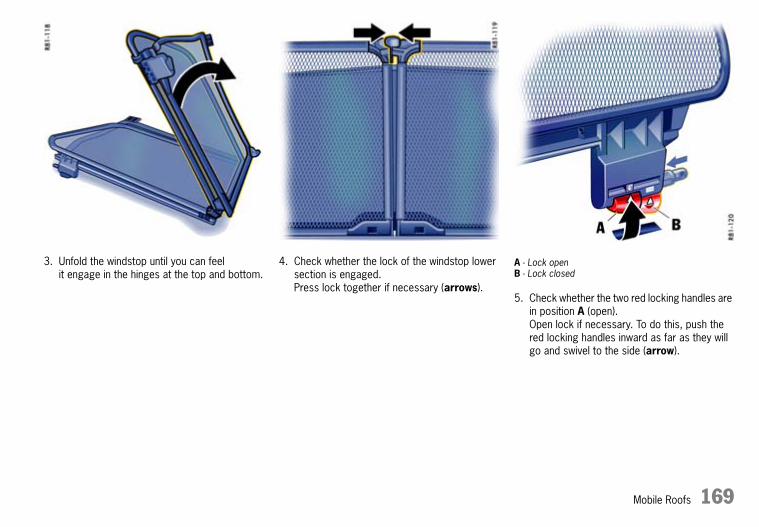
Mobile Roofs 169
3. Unfold the windstop until you can feel it engage in the hinges at the top and bottom.
4. Check whether the lock of the windstop lower section is engaged.Press lock together if necessary (arrows).
A - Lock openB - Lock closed
5. Check whether the two red locking handles are in position A (open).Open lock if necessary. To do this, push the red locking handles inward as far as they will go and swivel to the side (arrow).
10_Turbo_20.book Seite 169 Freitag, 7. August 2009 12:55 12

170 Mobile Roofs
6. Insert the fastening tabs C of the windstop into the guides of the seat belts.Make sure that the plastic pin E engages in the centre guide of the windstop.
7. Press red locking handles inwards and swivel downwards. The spring pushes the square pins of the locks into the receptacles D in the side trim panels.Check whether the square pins are correctly engaged.
8. Lift the upper section of windstop if required.
10_Turbo_20.book Seite 170 Freitag, 7. August 2009 12:55 12

Mobile Roofs 171
A - Lock openB - Lock closed
Removing the windstop
1. Fold back the upper section of windstop.
2. Move both red locking handles to position A (open).
3. Pull the windstop out of the guides of the seat belts.
4. Fold the windstop together so that the split windstop lower section is on the outside.
5. Place the windstop in the protective bag in the luggage compartment and close the zip of the protective bag.Please observe the chapter “INSTALLING THE WINDSTOP” on Page 168.
10_Turbo_20.book Seite 171 Freitag, 7. August 2009 12:55 12

172 Mobile Roofs
Hardtop
Storage
Your Porsche partner will be pleased to advise you about correct hardtop storage.
Provide a clean, soft surface on which to place the hardtop.
Removing the hardtop
1. Open all four side windows.
2. Pull off the plastic cover of the front hardtop lock (arrow).
3. Press the red locking button A of the front locking lever.Fully open locking lever B.
10_Turbo_20.book Seite 172 Freitag, 7. August 2009 12:55 12

Mobile Roofs 173
4. Take the unlocking handle D from the oddments tray between the front seats.
5. Position the unlocking handle D on the dot marking.Carefully lever out the plastic covers C on both sides of the hardtop.
6. Insert the unlocking handle D into one of the rear hardtop locks.Loosen fastening screw by approx. 2 turns, take off handle, and completely loosen screw by hand (approx. 8 turns).
7. Pull out fastening screw up to stop and turn 2 turns anti-clockwise (secure against damage).
8. Repeat the procedure on the other side of the hardtop.
9. Together with a second person on the other side, grasp the hardtop at points E and F.
d Warning!
Risk of pinching at points “F”.
f Lift the hardtop evenly on both sides.
10.First lift the hardtop out of the locks at the rear.Carefully lift the hardtop up and over the vehicle toward the rear.
10_Turbo_20.book Seite 173 Freitag, 7. August 2009 12:55 12

174 Mobile Roofs
11.Carefully unclip both protective covers J.
12.Fit both plastic covers C into the trim panel.The marking dot must point to the rear.These plastic covers are also used with the hardtop.
13.Close the front locking lever.Fit the plastic cover of the front hardtop lock.
Fitting the hardtop
d Caution!
Risk of damage to the windstop and hardtop.
f Always remove the windstop before fitting the hardtop. Please observe the chapter “WINDSTOP” on Page 168.
1. Open all four side windows.
2. Take the unlocking handle D from the oddments tray between the front seats.
3. Position the unlocking handle D on the dot marking.Carefully lever out both plastic covers C.
4. Fit both protective covers J into the trim panel.
10_Turbo_20.book Seite 174 Freitag, 7. August 2009 12:55 12

Mobile Roofs 175
5. Pull off the plastic cover from the front hardtop lock.
6. Press red locking button of the front locking lever.Fully open the locking lever.
10_Turbo_20.book Seite 175 Freitag, 7. August 2009 12:55 12

176 Mobile Roofs
7. Check whether the rear threaded joints on the hardtop are loosened (2 turns clockwise).
8. Together with a second person on the other side, grasp the hardtop at points E and F.
9. Carefully lift the hardtop up and over the vehicle from behind.
10.First push the hardtop fully into the guides on the windscreen frame.Then carefully lower the hardtop into the locking elements at the rear.
d Caution!
Risk of damage due to inadvertent operation of the convertible top when the hardtop is fitted.
f Make sure that the front locking lever G is always properly locked.This disables the convertible-top drive.
10_Turbo_20.book Seite 176 Freitag, 7. August 2009 12:55 12

Mobile Roofs 177
11.Swivel the front locking lever G to the rear.The locking hook H must engage in the windscreen frame (arrow).The white marking line J on the red locking button must be visible when the hardtop is locked properly.
12.Fit the plastic cover of the front hardtop lock.
13.Tighten the fastening screw by hand. Then tighten the fastening screw with the unlocking handle D (tightening torque 46 Nm (34 ftlb.)).
14.Repeat the procedure on the other side of the hardtop.
15.Fit both plastic covers C into the trim panels of the rear hardtop locks so that the marking dots are opposite each other.
16.Store unlocking handle in oddments tray between the front seats.
10_Turbo_20.book Seite 177 Freitag, 7. August 2009 12:55 12
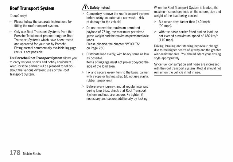
178 Mobile Roofs
Roof Transport System(Coupé only)
f Please follow the separate instructions for fitting the roof transport system.
f Only use Roof Transport Systems from the Porsche Tequipment product range or Roof Transport Systems which have been tested and approved for your car by Porsche.Fitting normal commercially available luggage racks is not possible.
The Porsche Roof Transport System allows you to carry various sports and hobby equipment.Your Porsche partner will be pleased to tell you about the various different uses of the Roof Transport System.
d Safety notes!
f Completely remove the roof transport system before using an automatic car wash – risk of damage to the vehicle!
f Do not exceed the maximum permitted payload of 75 kg, the maximum permitted gross weight and the maximum permitted axle loads.Please observe the chapter “WEIGHTS” on Page 250.
f Distribute load evenly, with heavy items as low as possible.Items of luggage must not project beyond the side of the load area.
f Fix and secure every item to the basic carrier with a rope or lashing strap (do not use elastic rubber tensioners).
f Before every journey, and at regular intervals during long trips, check that Roof Transport System and load are secure. Re-tighten if necessary and secure additionally by locking.
When the Roof Transport System is loaded, the maximum speed depends on the nature, size and weight of the load being carried.
f But never drive faster than 140 km/h (90 mph).
f With the basic carrier fitted and no load, do not exceed a maximum speed of 180 km/h (110 mph).
Driving, braking and steering behaviour change due to the higher centre of gravity and the greater wind-resistant area. You should adapt your driving style appropriately.
Since fuel consumption and noise are increased with the roof transport system fitted, it should not remain on the vehicle if not in use.
10_Turbo_20.book Seite 178 Freitag, 7. August 2009 12:55 12

Maintenance, Car Care 179
Maintenance, Car CareNotes on Maintenance ................................ 180Coolant Level............................................. 181Engine Oil Level ......................................... 182Brake Fluid Level........................................ 184Fuel........................................................... 186Fuel Can .................................................... 187Emission Control System ............................ 188Washer Fluid .............................................. 189Power Steering .......................................... 190Air cleaner ................................................. 191Combination filter ....................................... 191Wiper Blades ............................................. 191Car Care Instructions.................................. 192
10_Turbo_20.book Seite 179 Freitag, 7. August 2009 12:55 12

180 Maintenance, Car Care
Notes on MaintenanceWe recommend that you use your Porsche partner for carrying out this work.Experienced, Porsche trained workshop personnel, supplied with the latest information as well as special tools and equipment are prerequisites for looking after your Porsche properly.
If you work on your vehicle yourself, you must do it with great care. Only in this way is operational reliability fully guaranteed.
Unskilled maintenance work performed during the guarantee period may cause you to lose your claims.
d Danger!
Risk of death, injury and fire during maintenance work.
f Do not smoke in the vicinity of the battery or fuel system, and do not use a naked flame.
f Only work on the vehicle in the open or in well-ventilated spaces.
f Take care when working near hot engine parts.
f Never start the engine when in confined spaces.
f Before working in the engine compartment, always switch the engine off and let it cool sufficiently.
f If you have to work on the engine while it is running, always put the handbrake on and put the gearshift lever in neutral or the PDK selector lever in position P.
f Take great care to ensure that hands, fingers, articles of clothing (ties, sleeves, etc.), necklaces or long hair cannot be drawn in by the engine-compartment blower, the drive belt or other moving parts.
f The engine-compartment blower is mounted on the engine compartment lid.After the engine is switched off, the engine compartment temperature is monitored for approx. 30 minutes.During this period, and depending on temperature, the engine-compartment blower may continue to run or start to run.Carry out work in these areas only with the engine off and exercise extreme caution.
f The radiators and radiator fans are in the front of the vehicle.The radiator fans in the front end of the car may be operating or unexpectedly start operating when the engine is switched on.Carry out work in these areas only with the engine switched off.
f When the ignition is on, all cables and wires of the ignition system carry a high voltage. Special care is therefore required.
f Always place the vehicle on stable supports if work has to be carried out under the vehicle.The car jack is not suitable for this.
f Refill fluids, e.g. engine oil, washer fluid, brake fluid or coolant, are hazardous to health.Store refill fluids out of reach of children and, if necessary, dispose of these fluids properly.
10_Turbo_20.book Seite 180 Freitag, 7. August 2009 12:55 12

Maintenance, Car Care 181
Coolant Levelf Please observe the chapter “NOTES ON
MAINTENANCE” on Page 180.
The coolant provides year-round protection from corrosion and freezing down to –35 °C.
f Use only antifreeze authorised by Porsche.
Check coolant level
The expansion tank for the coolant is located on the left-hand side of the engine compartment.
f Check the coolant level regularly.
When the engine is cold and the car is level, the coolant level must be between the minimum and maximum marks.
Topping up coolant
d Warning!
Risk of scalding from hot coolant.
f Do not open the cap of the expansion tank while the engine is hot.
1. Switch engine off and let it cool.Please observe the chapter “COOLING SYSTEM” on Page 95.
2. Cover the expansion tank cap with a cloth.Open cap carefully and allow overpressure to escape. Then unscrew cap completely.
3. Only add a mixture of antifreeze and water in equal parts, and do not exceed the Max. mark.
Antifreeze in coolant:50 % provides protection against freezing down to –35 °C60 % provides protection against freezing down to –50 °C
4. Screw cap on firmly.
If pure water is added in an emergency, the mixing ratio will have to be corrected. Marked loss of coolant indicates leakage in the cooling system.
f The cause must be eliminated without delay. Consult a qualified specialist workshop. We recommend a Porsche partner for this work as they have trained workshop personnel and the necessary parts and tools.
Radiator fans
The radiators and radiator fans are in the front of the vehicle.
d Warning!
Risk of injury. The radiator fans in the front end of the car may be operating or unexpectedly start operating when the engine is switched on.
f Carry out work in these areas only with extreme care and with the engine off.
10_Turbo_20.book Seite 181 Freitag, 7. August 2009 12:55 12

182 Maintenance, Car Care
Engine Oil Levelf Check the oil level regularly using the on-board
computer before refuelling the vehicle.Please observe the chapter “ON-BOARD COMPUTER” on Page 102.
The difference between the Min and Max markings on the segment display of the on-board computer is approx. 1.25 litres.One segment of the display corresponds to a top-up quantity of approx. 0.4 litres.
Topping up engine oil
Porsche recommends .
The right oil for your vehicle.
1) Generally, you can find details of the manufacturer approvals on the oil containers or as a notice displayed by the retailer.The current approval status is also available from your Porsche partner.2) SAE viscosity class - Example: SAE 0W - 40 Specification 0W = Viscosity specification for low temperatures (winter).Specification 40 = Viscosity specification for high temperatures.3) For all temperature ranges.4) For the temperature range above –25 °C.
Always observe the following points:
– Use engine oils approved by Porsche only. This is a precondition for optimum and problem-free operation of your vehicle.
– The engine oil is changed regularly during servicing.It is important that the service intervals, particularly the oil change intervals, are
observed in accordance with the specifications in the “Guarantee & Maintenance” booklet.
– Oils approved by Porsche can be mixed with each other.
– Porsche engines are designed so that no oil additives may be used.
– A label is located in the engine compartment, which provides you with information on suitable oil for your engine.
Your Porsche partner will be pleased to advise you.
d Warning!
Risk of burning from hot parts in engine compartment.The engine compartment blower on the engine compartment lid can start up even with the engine off.
f Exercise extreme caution when working on the engine compartment.Please observe the chapter “NOTES ON MAINTENANCE” on Page 180.
f Top up engine oil only with the engine off.
Note
The Check Engine warning light may light up if the cap of the oil filler opening is opened while the engine is running.
Complies with approval1)
Viscosity class2)
Porsche A40 SAE 0W - 403)
SAE 5W - 404)
SAE 5W - 504)
10_Turbo_20.book Seite 182 Freitag, 7. August 2009 12:55 12

Maintenance, Car Care 183
1. Measure the oil level and read off the required top-up quantity on the on-board computer.
2. Switch off the engine.
3. Turn the oil filler cap anti-clockwise through approx. 90° and pull the oil filler tube out fully by means of the cap.
4. Fold down the oil filler cap.
5. Add at most half a litre of engine oil at a time.Never add more engine oil than required to reach the Max marking.
6. Fold up oil filler cap.
7. Push in oil filler tube fully and turn cap clockwise until you feel it reach its end position.
8. Measure oil level again with the on-board computer. Switch off the engine.
9. If necessary, repeat the process and add more engine oil as required.
10_Turbo_20.book Seite 183 Freitag, 7. August 2009 12:55 12

184 Maintenance, Car Care
Brake Fluid Levelf Please observe the chapter “NOTES ON
MAINTENANCE” on Page 180.
f Only use genuine Porsche brake fluid or a brake fluid of similar quality which has been manufactured according to Porsche specifications and product requirements.
d Warning!
Brake fluid is toxic and attacks paintwork and other surfaces.
f Store brake fluid out of the reach of children.
f Take care while topping up brake fluid not to soil the luggage compartment or items of luggage.
Checking the brake fluid level
The reservoir for the hydraulic brake and clutch systems is in the luggage compartment.
1. Open and remove covering flap A.
2. Regularly check the brake fluid level at the transparent expansion tank through the window B.The fluid level should always be between the minimum and maximum marks.
A slight decrease in the fluid level due to wear and automatic readjustment of the disc brakes is normal.If, however, the fluid level falls markedly or below the minimum mark, the brake system may have developed a leak.
f Have the brake system checked without delay. Consult a qualified specialist workshop. We recommend a Porsche partner for this work as they have trained workshop personnel and the necessary parts and tools.
10_Turbo_20.book Seite 184 Freitag, 7. August 2009 12:55 12

Maintenance, Car Care 185
Changing the brake fluid
Brake fluid absorbs moisture from the air over time. This accumulation of water lowers the boiling point and, under certain operating conditions, can affect the braking action.Therefore, have the brake fluid changed in accordance with the change intervals stated in the “Guarantee and Maintenance” booklet.
– The warning lights on the instrument panel and on the on-board computer indicate an insufficient brake fluid level.
– If the warning light lights up on the instrument panel and the warning message appears on the on-board computer in combination with a larger pedal travel, a brake circuit may have failed.
If the warning lights should light up whilst driving:
f Stop immediately in a suitable place.
f Do not continue driving.Consult a qualified specialist workshop. We recommend a Porsche partner for this work as they have trained workshop personnel and the necessary parts and tools.
Warning light and warning message
10_Turbo_20.book Seite 185 Freitag, 7. August 2009 12:55 12
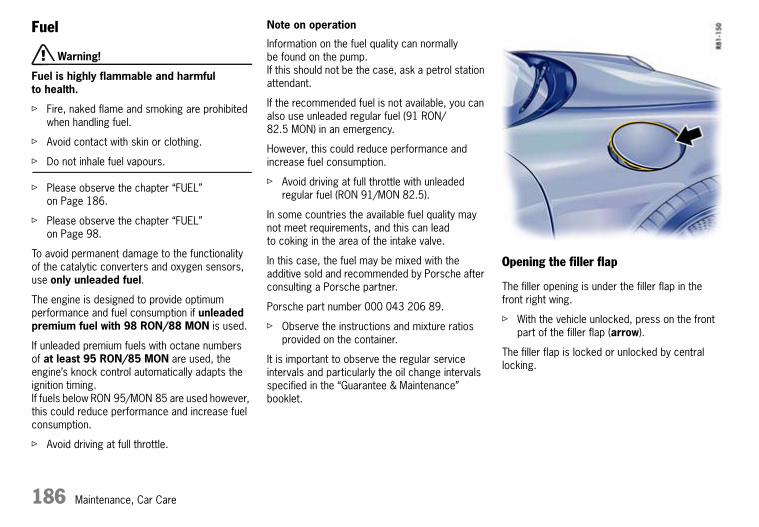
186 Maintenance, Car Care
Fuel
d Warning!
Fuel is highly flammable and harmful to health.
f Fire, naked flame and smoking are prohibited when handling fuel.
f Avoid contact with skin or clothing.
f Do not inhale fuel vapours.
f Please observe the chapter “FUEL” on Page 186.
f Please observe the chapter “FUEL” on Page 98.
To avoid permanent damage to the functionality of the catalytic converters and oxygen sensors, use only unleaded fuel.
The engine is designed to provide optimum performance and fuel consumption if unleaded premium fuel with 98 RON/88 MON is used.
If unleaded premium fuels with octane numbers of at least 95 RON/85 MON are used, the engine’s knock control automatically adapts the ignition timing. If fuels below RON 95/MON 85 are used however, this could reduce performance and increase fuel consumption.
f Avoid driving at full throttle.
Note on operation
Information on the fuel quality can normally be found on the pump.If this should not be the case, ask a petrol station attendant.
If the recommended fuel is not available, you can also use unleaded regular fuel (91 RON/82.5 MON) in an emergency.
However, this could reduce performance and increase fuel consumption.
f Avoid driving at full throttle with unleaded regular fuel (RON 91/MON 82.5).
In some countries the available fuel quality may not meet requirements, and this can lead to coking in the area of the intake valve.
In this case, the fuel may be mixed with the additive sold and recommended by Porsche after consulting a Porsche partner.
Porsche part number 000 043 206 89.
f Observe the instructions and mixture ratios provided on the container.
It is important to observe the regular service intervals and particularly the oil change intervals specified in the “Guarantee & Maintenance” booklet.
Opening the filler flap
The filler opening is under the filler flap in the front right wing.
f With the vehicle unlocked, press on the front part of the filler flap (arrow).
The filler flap is locked or unlocked by central locking.
10_Turbo_20.book Seite 186 Freitag, 7. August 2009 12:55 12

Maintenance, Car Care 187
If there is a fault in the automatic unlocking system:
f Open the passenger’s door.
f Pull the ring in the right-hand door aperture (arrow).
Refuelling
Total capacity
f Please observe the chapter “CAPACITIES” on Page 249.
1. Stop the engine and switch off the ignition.
2. Slowly unscrew the tank cap.Hang the tank cap on the filler flap by its plastic strap.The hissing noise heard when the tank filler cap is opened is “normal” and does not indicate a fault in the tank system.
3. Insert the pump nozzle fully into the filler neck with the handle of the pump nozzle facing down.
4. Do not add further fuel once the correctly operated automatic pump nozzle has switched off.Fuel could spray or could run over when heated.
5. Replace the tank cap immediately after refuelling and turn it until you hear it and feel it engage.
If you lose the tank filler cap, you must replace it with an original part only.
d Caution!
Risk of damage. Decorative film may fade if it comes into contact with fuel.
f Clean up any spilled fuel immediately.
Fuel Can
d Danger!
Risk of fire or explosion if the fuel can is damaged in an accident and fuel escapes.Escaping vapours can be harmful to health.
f Do not carry a fuel can on journeys.
f Observe the relevant laws.
10_Turbo_20.book Seite 187 Freitag, 7. August 2009 12:55 12

188 Maintenance, Car Care
Emission Control SystemClosed-loop three-way catalytic converters, combined with oxygen sensors and an electronic control unit, represent the most effective emission control system.
To ensure the efficiency of the emission control system, always have your vehicle serviced at the specified intervals.
To avoid permanent damage to the functionality of the catalytic converters and oxygen sensors, use unleaded fuel only.
The fuel tank ventilation system prevents fuel vapours from the tank entering the environment.
Tips on driving
Faulty preparation of the fuel/air mixture can cause the catalytic converters to overheat and can destroy them.
d Warning!
Risk of damage to emission control system.
f Avoid frequent and prolonged use of the starter if the engine does not start.
f If misfiring occurs while driving (identifiable by rough running of the engine, loss of power or an illuminated Check Engine warning light), have the fault remedied immediately. Consult a qualified specialist workshop. We recommend a Porsche partner for this work as they have trained workshop personnel and the necessary parts and tools.
f Avoid high cornering speeds after the fuel-level warning light lights up.
f Never drive the tank dry.
f Tow-start or push-start the car only if the engine is cold.Vehicles with PDK transmission cannot be tow-started or push-started.
Risk of fire in the area of the exhaust system.
f Do not apply additional undersealing or rust protection agent on or near the exhaust manifolds, exhaust pipes, catalytic converters or heat shields.The protective material could overheat and ignite while you are driving.
f Do not drive or park your vehicle where combustible materials, such as dry grass or leaves, can come into contact with the hot exhaust system.
10_Turbo_20.book Seite 188 Freitag, 7. August 2009 12:55 12

Maintenance, Car Care 189
Washer FluidThe reservoir with blue screw cap is located in the rear left of the luggage compartment (direction of travel).
Capacity
f Please observe the chapter “CAPACITIES” on Page 249.
Adding washer fluid
Clean water is generally not enough to clean the windscreen and headlights.
Depending on the season, add the corresponding additives to the water in a suitable mixture ratio.
Only use window cleaner concentrate which meets the following requirements:
– dilutability 1:100,
– phosphate free,
– suitable for plastic headlight lenses.
We recommend that you use concentrated window cleaner approved by Porsche. Your Porsche partner will be pleased to advise you.
Summer filling
Water + concentrated window cleaner in the mixture ratio stated on the container.
Winter filling
Water + antifreeze + concentrated window cleaner in the mixture ratio stated on the container.
f Please observe all instructions on the concentrated window cleaner or antifreeze containers.
Adding washer fluid
1. Undo the cap (arrow).
2. Top up the washer fluid and carefully close the cap.
If less than approx. 0.5 litre remains, a warning message appears on the on-board computer.
f Add washer fluid.
Warning message
10_Turbo_20.book Seite 189 Freitag, 7. August 2009 12:55 12

190 Maintenance, Car Care
Power Steering
d Warning!
Risk of accident. When the engine is stationary (e.g. when the car is on tow) or the hydraulic system fails, there is no power assisted steering.Therefore, substantially more force will have to be exerted.
f Exercise great care when on tow.
f Have the fault remedied.Consult a qualified specialist workshop. We recommend a Porsche partner for this work as they have trained workshop personnel and the necessary parts and tools.
Note
The flow noise heard at full steering lock is system related and does not indicate a defect in the steering system.
Checking hydraulic fluid
f Please observe the chapter “NOTES ON MAINTENANCE” on Page 180.
f Only use genuine Porsche hydraulic fluid or a hydraulic fluid of similar quality which has been manufactured according to Porsche specifications and product requirements.
Check the fluid level with the engine stopped and cold (approx. 20 °C).
1. Open the engine compartment lid.
2. Open the reservoir cap.
3. Wipe dipstick.Close the cap and re-open. The fluid level should be between the “MIN” and “MAX” marks on the dipstick.Add hydraulic fluid if necessary.
4. Close cap carefully.
f If the fluid level has dropped significantly, have the cause remedied immediately. Consult a qualified specialist workshop. We recommend a Porsche partner for this work as they have trained workshop personnel and the necessary parts and tools.
10_Turbo_20.book Seite 190 Freitag, 7. August 2009 12:55 12

Maintenance, Car Care 191
Air cleanerf Please observe the chapter “NOTES ON
MAINTENANCE” on Page 180.
Regular replacement of the filter element is part of servicing.
f In dusty conditions, check the filter element more frequently and replace if necessary.
Combination filterThe fresh air passing through the combination filter into the passenger compartment is virtually free of dust, pollen, and unpleasant odours.
f If the outside air is polluted by exhaust fumes, press the circulating-air button.
A dirty filter can be the cause of reduced air throughput:
f Have the filter replaced. Consult a qualified specialist workshop. We recommend a Porsche partner for this work as they have trained workshop personnel and the necessary parts and tools.
Regular filter replacement is part of servicing.
Wiper BladesWiper blades that are in perfect condition are vital for a clear view.
f Replace the wiper blades twice per year (before and after the cold season) or if wiper performance deteriorates or the blades are damaged.
d Caution!
Risk of damage if wiper arm accidentally falls back onto the windscreen.
f Always hold the wiper arm securely when replacing the wiper blade.
Risk of damage if wiper blades that are frozen in place are loosened incorrectly.
f Thaw the wiper blades before loosening them.
Maintenance note
f Periodically clean the wiper blades with a window cleaner, especially after the vehicle has been washed in a car wash. We recommend Porsche window cleaner. If they are very dirty (e.g. with insect remains), they can be cleaned with a sponge or cloth.
If the wiper blades judder or squeak, this may be due to the following:
– If the vehicle is washed in an automatic car wash, wax residues may adhere to the windscreen. These wax residues can only be removed by using a concentrated window cleaner.
– The wiper blades may be damaged or worn.
f Replace damaged wiper blades as soon as possible.
f Please observe the chapter “WASHER FLUID” on Page 189.
Please contact your Porsche partner for further information.
Replacing wiper blades
f Please read the separate instructions for fitting wiper blades as supplied by the manufacturer.
f We recommend that you get your Porsche partner to replace the wiper blades.
d Caution!
Risk of damage.If the wiper blades are not changed properly, they can come loose when the car is moving.
f Check whether the wiper blades are seated securely.The wiper blades must engage in the wiper arm properly.
10_Turbo_20.book Seite 191 Freitag, 7. August 2009 12:55 12

192 Maintenance, Car Care
Car Care InstructionsRegular, skilled care helps to maintain the value of your Porsche and can be a precondition for the upholding of claims under the vehicle guarantee.
You can obtain suitable care products at your Porsche partner, individually or as a complete set.
f Follow the instructions for use on the packaging of care products.
f Keep care products out of reach of children.
f If necessary, dispose of these fluids properly.
In order to ensure that the vehicle’s condition is expertly checked and that the guarantee remains valid for the full period, every Porsche partner will inspect the level of care of the vehicle and record the results in writing.The Porsche partner will issue a Condition Report. The condition is additionally certified in the “Guarantee and Maintenance” booklet under “Long-life Guarantee Condition Report”.
High-pressure cleaning equipment, steam cleaners
d Warning!
High-pressure cleaning equipment and steam cleaners can damage the following components:
– Convertible top,
– Tyres,
– Logos, emblems, decorative film
– Painted surfaces,
– Generator,
– ParkAssist sensors.
f Please observe the operating instructions from the unit manufacturer.
f When cleaning with a flat-jet nozzle or a so-called “dirt blaster”, maintain a minimum distance of 50 cm.
f Never use high-pressure cleaning equipment or steam cleaners with a round-jet nozzle.High-pressure cleaning equipment or a steam cleaner with a round nozzle will damage your vehicle.The tyres are particularly susceptible to damage.
f Do not point the cleaning jet directly at any of the aforementioned components.
Decorative film
d Caution!
Risk of damage due to separation of the decorative film when using high-pressure cleaning equipment or steam cleaners.
f Do not use high-pressure cleaning equipment or steam cleaners to clean decorative films.
Washing
The best protection for the vehicle from the damaging effects of the environment is frequent washing and preservation. The underside of the vehicle should also be thoroughly washed at the end of the gritting season at the latest.
The longer road salt, road dust, industrial dust, insect remains, bird excrement, and tree exudations (resin, pollen), etc. are allowed to remain on the bodywork, the more serious is their harmful effect.
Washing a vehicle by hand is more environmentally harmful than using a car wash.
f Wash your vehicle only at sites provided for this purpose to prevent soot, grease, oil and heavy metals from entering the environment.
Dark paints make even the smallest surface blemishes (scratches) more conspicuous than lighter colours.
10_Turbo_20.book Seite 192 Freitag, 7. August 2009 12:55 12

Maintenance, Car Care 193
Dark colours are also more susceptible to scratching because of the composition of their pigments and require particularly careful paint care.
f Do not wash your Porsche in direct sunlight or when its body is hot.
f When washing by hand, use a car shampoo, plenty of water, a soft sponge or washing brush.We recommend Porsche car shampoo.
f Begin washing the vehicle by thoroughly wetting the paintwork and rinsing the heavy dirt off.
f After washing the vehicle, rinse it thoroughly with water and leather it dry.Do not use the same leather to rub down as you use for cleaning the windscreen and windows.
Reduced or uneven braking action may be caused by wet brakes.
f After washing the vehicle, test the brakes and steering and briefly brake the brake discs dry.When doing so, make sure that following traffic is not affected.
Car washes
Optional add-on parts or parts which project beyond the contours of the vehicle may be damaged by design features of car washes.
The following parts are particularly at risk:
– convertible top (hot wax treatment must not be used, as the wax attacks the convertible top material)
– external antenna (always unscrew),
– windscreen wipers (always switch them off to prevent them wiping unintentionally in intermittent or sensor operation),
– roof transport system (always remove completely),
– fixed rear spoiler or extended rear spoiler,
– wheels (the wider the rim and the lower the tyre height, the greater the risk of damage),
– high-gloss wheels (to prevent these from getting scratched, do not clean with the wheel-cleaning brushes of the car wash).
f Please consult the operator before using automatic car washes.
f Wash and leather by hand all points not reached by a car wash, such as door and lid seams or door sills.
Con. top
The useful life and appearance of the convertible top depend largely on expert care and operation.
Unskilful care and operation can damage the convertible top or make it leak.Never remove snow and ice with sharp-edged objects.
Cleaning the convertible top
d Caution!
Risk of damage due to the cleaning jet of the high-pressure cleaning equipment or steam cleaners or hot wax treatment.
f Do not clean the convertible top with high-pressure cleaning equipment or steam cleaners.
f No hot wax treatment.
Do not wash the convertible top every time you wash the car.Normally, rinsing the convertible top with clean water is sufficient.
f Brush dust off the convertible top in the direction of the weave using a soft brush.
10_Turbo_20.book Seite 193 Freitag, 7. August 2009 12:55 12

194 Maintenance, Car Care
f Only if there is heavy dirt, wet the convertible top with lukewarm water and a wash-shampoo & convertible-top cleaner, and rub gently using a sponge or soft brush. Rinse wash-shampoo & convertible-top cleaner thoroughly off the convertible top with clean water. We recommend Porsche wash-shampoo.
f Treat the convertible top at least once a year with a convertible-top care product after washing.Do not allow the convertible-top care product to come into contact with paint or glass. If it does, remove immediately.
f If there is leakage in the convertible-top cover or at its seams and folds, a special convertible-top care product can be used.
f Please note the information on the containers. We recommend Porsche convertible-top care product.
f Remove bird excrement immediately. The acid this contains makes the rubber swell, and the convertible top will become leaky.
f Open the convertible top only when completely dry, otherwise damp stains and abrasion marks may occur which cannot be removed.
f Try to remove spots from the convertible-top cloth by rubbing carefully with a soft rubber sponge.
Door lock
f To prevent the door lock freezing during the cold season, cover the lock barrel during washing.
f If the lock freezes nevertheless, use an ordinary de-icer. In many cases, a well warmed key can help.Never use excessive force.
Paint
To protect the paint on your vehicle in the best possible way against mechanical and chemical damage, you should
– preserve it regularly,
– polish it if necessary,
– remove spots and stains and
– repair damaged paintwork.
f Do not apply care products containing silicone to the convertible top and windows.
General information
f Never rub a dusty vehicle with a dry cloth, because the grains of dirt will damage the paintwork.
f Do not treat matt-painted components with preservatives or polish, otherwise the matt effect will be lost.
Preservation
The paint surface becomes dull over time due to weathering.
f Preserve paint regularly.
f Apply paint preservative after washing the vehicle to preserve the paintwork.Always observe the manufacturer’s instructions.This keeps the paint shiny and elastic. Dirt is prevented from adhering to the paint surface and industrial dust is prevented from penetrating the paint.
Your Porsche partner will be pleased to advise you.
Polishing
f Only when the original polish can no longer be obtained using preservatives should paint polish be used to clean the paint.We recommend Porsche paint polish.
10_Turbo_20.book Seite 194 Freitag, 7. August 2009 12:55 12

Maintenance, Car Care 195
Removing spots and stains
f Remove tar spatters, traces of oil, insects etc. as soon as possible with an insect remover, as they discolour the paint if left to work on it over time.
f Carefully wash the treated areas again.
Repairing minor paint damage
f Have minor paint damage (cracks, scratches or stone damage) repaired immediately before corrosion begins. Consult a qualified specialist workshop. We recommend a Porsche partner for this work as they have trained workshop personnel and the necessary parts and tools.
If corrosion has already formed, it must be thoroughly removed. An anti-corrosion primer is then applied, followed by top coat paint.Paint data can be found on the vehicle data bank.
f Please observe the chapter “VEHICLE DATA CARRIER” on Page 244.
Cleaning the engine compartment
d Caution!
Risk of damage to generator.
f Do not point the cleaning jet directly at the generator, or cover the generator.
Effective rust-proofing is particularly important during the cold weather season. If the vehicle is driven frequently in areas where salt has been spread on the roads, the engine compartment should be cleaned thoroughly after the cold weather season to prevent salt from causing any lasting damage.
Windows
f Clean all windows regularly, inside and out, with window cleaner.We recommend the Porsche window cleaner.Do not use the same leather for painted surfaces and for drying the windows.Preservative residues could reduce transparency.
f Remove insect residues with insect remover.
Note
Door windows feature a water-repellent (hydrophobic) coating which prevents soiling of the windows. This coating is subject to natural wear and can be renewed.
f Consult a qualified specialist workshop. We recommend a Porsche partner for this work as they have trained workshop personnel and the necessary parts and tools.
10_Turbo_20.book Seite 195 Freitag, 7. August 2009 12:55 12

196 Maintenance, Car Care
Wiper blades
Wiper blades that are in perfect condition are vital for a clear view.
f Please observe the chapter “WIPER BLADES” on Page 191.
f Replace the wiper blades twice per year (before and after the cold season) or if wiper performance deteriorates or the blades are damaged.
f Periodically clean the wiper blades with a window cleaner, especially after the vehicle has been washed in a car wash.We recommend the Porsche window cleaner.If they are very dirty (e.g. with insect remains), they can be cleaned with a sponge or cloth.
If the wiper blades judder or squeak, this may be due to the following:
– If the vehicle is washed in an automatic car wash, wax residues may adhere to the windscreen. These wax residues can only be removed by using a concentrated window cleaner.
– The wiper blades may be damaged or worn.
f Replace damaged or worn wiper blades immediately.
f Please observe the chapter “WASHER FLUID” on Page 189.
Please contact your Porsche partner for further information.
Stainless steel tailpipes
Stainless steel tailpipes may suffer discoloration caused by contamination, major heat build-up and combustion residue.
The original gloss can be achieved again using commercially available polishing paste or metal polish.
Undersealing
The underside of the vehicle is lastingly protected against chemical and mechanical effects.Damage to this protective layer while driving cannot be ruled out.The vehicle underside should therefore be checked and repaired at regular intervals by a qualified specialist workshop.
d Warning!
Risk of fire in the area of the exhaust system.
f Do not apply additional undersealing or rust protection agent on or near the exhaust manifolds, exhaust pipes, catalytic converters or heat shields.The protective material could overheat and ignite while you are driving.
After washing the underside, cleaning the engine or repairing a unit, the unprotected parts must be preserved using suitable materials.
Light alloy wheels
f Please observe the chapter “CAR WASHES” on Page 193.
Metal particles (e.g. brass or copper in brake dust) must not remain too long on light alloy wheels.Contact corrosion can cause pitting.
Cleaners with an oxide-removing effect or the wrong pH value, as are commonly used for other metals, as well as mechanical tools and products, will damage the oxide layer and are therefore unsuitable.
f If possible, wash the wheels every two weeks with a sponge or washing brush. If the wheels are exposed to road salt, grit or industrial dust, weekly cleaning is necessary.Use only cleaners for alloy wheels (pH value 9.5). Products with the wrong pH value can destroy the protective layer on the wheels.We recommend Porsche cleaner for light alloy rims.
10_Turbo_20.book Seite 196 Freitag, 7. August 2009 12:55 12

Maintenance, Car Care 197
f Every three months, after cleaning, grease the wheels with car wax or an acid-free grease (Vaseline).Rub the grease in well with a soft cloth.
d Warning!
Danger of accident if cleaning agents (e.g. wheel cleaning agents) come into contact with the brake discs. The resulting film on the brake discs can impair braking performance.
f Make sure that no cleaning agent comes into contact with the brake discs.
f If cleaning agent has come into contact with the brake discs, thoroughly clean the brake discs with a strong jet of water.
f Paying attention to any road users behind you, dry the brake discs by applying the brakes.
Door, roof, lid and window seals
d Caution!
The lubricant coating on the inner door seals, convertible top and hardtop seals may be damaged by unsuitable cleaning and care agents.
f Do not use any chemical cleaning agents or solvents.
f Do not use any preservative agents.
f Wash dirt (e.g. abrasion, dust, road salt and grit) from all seals regularly using warm soapy water.
f If there is a risk of frost, protect the outer door seals and lid seals against freezing into place with a suitable care product.
Headlights, lights, interior and exterior plastic parts, adhesive films
f Use only clean water and a little dishwashing detergent to clean headlights, lights, decals, plastic parts and surfaces.Use a soft sponge or a soft, lint-free cloth.
Note
An interior window cleaner can also be used to clean plastic surfaces (always read the cleaning instructions on the container). We recommend Porsche interior window cleaner.
f Gently wipe the surface without applying too much pressure.
f Do not clean when dry.
f Never use other chemical cleaners or solvents.
f Wipe down cleaned surfaces using a damp cloth.
Leather
The natural surface characteristics of leather, such as creases, healed scars, insect sting marks, structural differences and slight variations in shade and grain add to the attractiveness of the natural leather product.
Observe the following care instructions:
d Caution!
The leather will be damaged by the use of unsuitable cleaning and care agents and by inappropriate treatment.
f Do not use caustic cleaners or hard cleaning aids.
f Perforated leather must under no circumstances get wet on its reverse side.
f All types of leather should be cleaned regularly to remove fine dust using a soft, damp, white woollen cloth or a commercially available microfibre cloth.
f Remove heavy contamination with a leather cleaner. Please always follow the instructions for use given on the containers.We recommend Porsche leather cleaners.
f Treat cleaned leather only with a leather care product.We recommend the Porsche leather care product.
10_Turbo_20.book Seite 197 Freitag, 7. August 2009 12:55 12

198 Maintenance, Car Care
Carpet, floor mats
f Use a vacuum cleaner or a brush (not too soft) for cleaning.
f Remove heavy dirt and stains with a stain remover.We recommend Porsche stain remover.
To protect carpets, the Porsche range of accessories includes mats of the correct size and with the appropriate fastening.
d Warning!
Risk of accident.
f Do not obstruct the pedal travel with floor mats.Secure floor mats properly – do not place them loosely on the floor.
Cleaning fabric linings
f Fabric linings on pillars, convertible top liner and sun blinds, etc. must be cleaned only using suitable cleaning agents or a suitable dry foam and a soft brush.
Cleaning airbag covers
d Danger!
There is a danger of severe or fatal injuries if operation of the airbag system is impaired by improper cleaning work.
f Do not make any modifications whatsoever to individual components such as the padded covers of the steering wheel, instrument panel, front seats and door panels.
f Let your Porsche partner clean these components.
Alcantara
Do not use a leather care product to clean Alcantara.
For regular care it is sufficient to clean the cover with a soft brush.
Heavy abrasion or rubbing when cleaning causes a lasting change in the surface.
Cleaning when lightly soiled
f Wet a soft cloth with water or a neutral soap solution and wipe off the dirt.
Cleaning when heavily soiled
f Wet a soft cloth with lukewarm water or thinned white spirit and dab the dirt from the outside in.
Cleaning the seat belts
f Use mild detergent to clean soiled belts.
f When drying, avoid direct sunlight.
f Only use suitable cleaning agents.
f Do not tint or bleach the belts.The belt fabric could be weakened, thus affecting safety.
Laying up your Porsche
If you wish to keep your Porsche off the road for a lengthy period, we recommend that you contact your Porsche partner. They will be glad to advise you about the necessary measures, e.g. corrosion prevention, care, maintenance and storage.
f Please observe the chapter “BATTERY” on Page 223.
10_Turbo_20.book Seite 198 Freitag, 7. August 2009 12:55 12

Practical Tips, Minor Repairs 199
Practical Tips, Minor RepairsNotes on Minor Repairs .............................. 200Tyres and Wheels....................................... 201Wheel Bolts ............................................... 206Changing a Wheel ...................................... 207Changing a Central Locking Wheel............... 209Flat Tyre.................................................... 215Electrical System ....................................... 219Battery ...................................................... 223Jump Lead Starting .................................... 228Bulb chart.................................................. 229Replacing Bulbs ......................................... 229Headlights ................................................. 230Number Plate Light..................................... 238Changing Light-Emitting Diodes and Long-Life Bulbs .................................... 238Changing headlights from left to right-hand traffic..................................... 239Headlight adjustment.................................. 240Towing and Tow-Starting............................. 241
10_Turbo_20.book Seite 199 Freitag, 7. August 2009 12:55 12

200 Practical Tips, Minor Repairs
Notes on Minor RepairsWe recommend that you use your Porsche partner for carrying out this work.Experienced, Porsche trained workshop personnel, supplied with the latest information as well as special tools and equipment are prerequisites for looking after your Porsche properly.
If you work on your vehicle yourself, you must do it with great care. Only in this way is operational reliability fully guaranteed.
Unskilled maintenance work performed during the guarantee period may cause you to lose your claims.
Warning triangle, first aid kit and tool kit
f Please observe the chapter “LUGGAGE COMPARTMENT” on Page 76.
Some countries require additional tools and special spare parts to be carried. Please make enquiries before driving abroad.
d Danger!
Risk of death, injury and fire during maintenance work.
f Do not smoke in the vicinity of the battery or fuel system, and do not use a naked flame.
f Only work on the vehicle in the open or in well-ventilated spaces.
f Take care when working near hot engine parts.
f Never start the engine when in confined spaces.
f Before working in the engine compartment, always switch the engine off and let it cool sufficiently.
f If you have to work on the engine while it is running, always put the handbrake on and put the gearshift lever in neutral or the PDK selector lever in position P.
f Take great care to ensure that hands, fingers, articles of clothing (ties, sleeves, etc.), necklaces or long hair cannot be drawn in by the engine-compartment blower, the drive belt or other moving parts.
f The engine-compartment blower is mounted on the engine compartment lid.After the engine is switched off, the engine compartment temperature is monitored for approx. 30 minutes.During this period, and depending on temperature, the engine-compartment blower may continue to run or start to run.Carry out work in these areas only with the engine off and exercise extreme caution.
f The radiators and radiator fans are in the front of the vehicle.The radiator fans in the front end of the car may be operating or unexpectedly start operating when the engine is switched on.Carry out work in these areas only with the engine switched off.
f When the ignition is on, all cables and wires of the ignition system carry a high voltage. Special care is therefore required.
f Always place the vehicle on stable supports if work has to be carried out under the vehicle. The car jack is not suitable for this.
f Refill fluids, e.g. engine oil, brake fluid or coolant, are hazardous to health.Store refill fluids out of reach of children and, if necessary, dispose of these fluids properly.
10_Turbo_20.book Seite 200 Freitag, 7. August 2009 12:55 12

Practical Tips, Minor Repairs 201
Tyres and WheelsThe service life of the tyres depends on correct inflation pressure, correct wheel alignment and also your driving style.Abrupt acceleration, high cornering speeds and heavy braking increase tyre wear. The tread wear is also greater at higher outside temperatures and on rough road surfaces. Just like the engine, tyres always require the correct operating conditions. When correctly treated, they are a long-lived safety component on your Porsche. For your own protection and that of other road users, you must observe the following instructions.
Load and speed
f Do not overload your vehicle. Be careful about the roof load. There is a danger from overloading+ insufficient tyre pressure+ high speed+ high outside temperature
(e.g. holiday driving).
Tyre pressure
The tyre pressure must match the prescribed value. Details on tyre pressure are available in the left door aperture.These values are for cold tyres (at approx. 20 °C).
f Check the tyre pressure at least every 2 weeks. Always check when tyres are cold.
f On vehicles with Tyre Pressure Monitoring:Please observe the chapter “TPM TYRE PRESSURE MONITORING” on Page 119.
When tyres are warm, the tyre pressure is increased.
f Never let air out of hot tyres. This could cause the tyre pressure to fall below the prescribed value.
Valve caps protect the valve from dust and dirt, and thus from leakage.
f Always screw caps down tightly.
f Replace missing caps immediately.
Insufficient tyre pressure can cause tyres to overheat and thus be damaged – even invisibly. Hidden tyre damage is not eliminated by subsequently correcting the tyre pressure.
Tyre damage
Cleaning with high-pressure cleaners can damage the tyres.
f Please observe the chapter “HIGH-PRESSURE CLEANING EQUIPMENT, STEAM CLEANERS” on Page 192.
d Warning!
Risk of accident due to hidden tyre damage. Tyres may burst, especially at high speeds.
f Check tyres, including the sidewalls, regularly for foreign bodies, nicks, cuts, cracks and bulges.
f Cross kerb edges slowly and at right angles if possible.Avoid driving over steep or sharp kerbs.
f In cases of doubt, have the wheel (particularly the inner side) checked by an expert.
10_Turbo_20.book Seite 201 Freitag, 7. August 2009 12:55 12
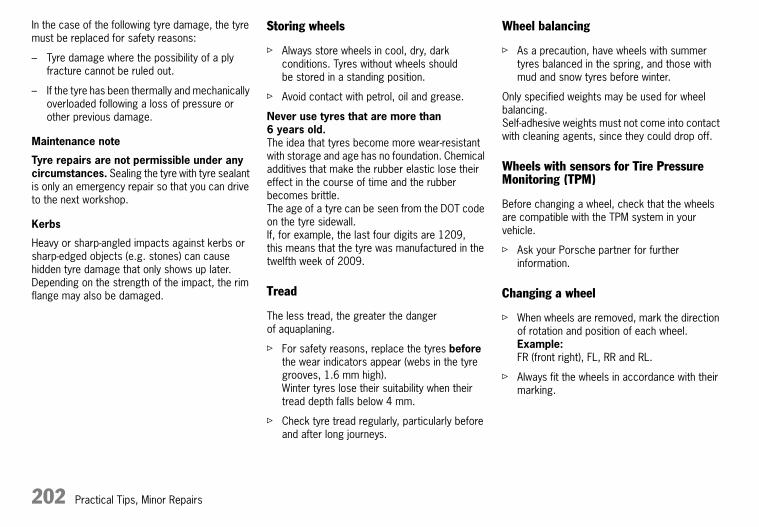
202 Practical Tips, Minor Repairs
In the case of the following tyre damage, the tyre must be replaced for safety reasons:
– Tyre damage where the possibility of a ply fracture cannot be ruled out.
– If the tyre has been thermally and mechanically overloaded following a loss of pressure or other previous damage.
Maintenance note
Tyre repairs are not permissible under any circumstances. Sealing the tyre with tyre sealant is only an emergency repair so that you can drive to the next workshop.
Kerbs
Heavy or sharp-angled impacts against kerbs or sharp-edged objects (e.g. stones) can cause hidden tyre damage that only shows up later.Depending on the strength of the impact, the rim flange may also be damaged.
Storing wheels
f Always store wheels in cool, dry, dark conditions. Tyres without wheels should be stored in a standing position.
f Avoid contact with petrol, oil and grease.
Never use tyres that are more than 6 years old. The idea that tyres become more wear-resistant with storage and age has no foundation. Chemical additives that make the rubber elastic lose their effect in the course of time and the rubber becomes brittle. The age of a tyre can be seen from the DOT code on the tyre sidewall. If, for example, the last four digits are 1209, this means that the tyre was manufactured in the twelfth week of 2009.
Tread
The less tread, the greater the danger of aquaplaning.
f For safety reasons, replace the tyres before the wear indicators appear (webs in the tyre grooves, 1.6 mm high).Winter tyres lose their suitability when their tread depth falls below 4 mm.
f Check tyre tread regularly, particularly before and after long journeys.
Wheel balancing
f As a precaution, have wheels with summer tyres balanced in the spring, and those with mud and snow tyres before winter.
Only specified weights may be used for wheel balancing. Self-adhesive weights must not come into contact with cleaning agents, since they could drop off.
Wheels with sensors for Tire Pressure Monitoring (TPM)
Before changing a wheel, check that the wheels are compatible with the TPM system in your vehicle.
f Ask your Porsche partner for further information.
Changing a wheel
f When wheels are removed, mark the direction of rotation and position of each wheel.Example:FR (front right), FL, RR and RL.
f Always fit the wheels in accordance with their marking.
10_Turbo_20.book Seite 202 Freitag, 7. August 2009 12:55 12

Practical Tips, Minor Repairs 203
Wheel alignment
Uneven tread wear indicates incorrect wheel alignment. The vehicle should be checked if this should be the case.
f Consult a qualified specialist workshop. We recommend a Porsche partner for this work as they have trained workshop personnel and the necessary parts and tools.
d Warning!
Risk of accident. You can lose control of the vehicle.If, during a journey, uneven running or vibrations occur that could be caused by damage to tyres or the car:
f Reduce speed immediately, but without braking sharply.
f Stop the vehicle and check the tyres.If no cause for the fault can be found, drive carefully to the nearest qualified specialist workshop.We recommend a Porsche partner for this work as they have trained workshop personnel and the necessary parts and tools.
Replacing tyres
There is no obligatory standard regarding permitted top speed above 240 km/h (150 mph) for tyres of ZR quality.
f Before fitting new tyres, find out about the current approval status.
f Use only tyre makes tested and approved by Porsche.
Basically, only tyres of the same make and with the same specification number (e.g. “N0”, “N1” ...) can be fitted.
In the initial period, tyres do not have their full traction.
f Therefore, do not drive above moderate speed during the first 100–200 km (60–120 miles).
If new tyres are fitted to only one axle, the different tread depths on the two axles can cause a marked change from the previous driving behaviour to which you have become accustomed.This is particularly true when new tyres are fitted to the rear axle.
The effect is reduced continuously, however, as tyre mileage increases.
f Adapt your driving style to the changed handling.
Tyres should only be fitted by specialist firms.
When a defective tyre is replaced, it should be noted that deviations in tread depth must not exceed 30 % on one axle.
f Do not use second-hand tyres if you do not know their history.
Valves
f Use only plastic valve caps.
The rubber valves must be replaced whenever the tyres are changed.In the case of metal valves, please observe the fitting and replacement instructions.Only use genuine Porsche metal valves or valves of the same quality, which are manufactured according to the specifications and production demands of Porsche.
f Protect the valve inserts against contamination with valve caps.Soiled valve inserts can cause a gradual loss of air.
10_Turbo_20.book Seite 203 Freitag, 7. August 2009 12:55 12

204 Practical Tips, Minor Repairs
Winter tyres
d Warning!
Risk of accident due to excessive speed.
f Always observe the permissible maximum speed of the respective winter tyre.
f Affix a sticker showing the maximum permissible speed in the driver’s field of vision.Observe the country-specific laws.
f Fit winter tyres to both axles in good time before the cold season begins.Your Porsche partner will be pleased to advise you.
f Before fitting new tyres, find out about the current approval status.
f Use only tyre makes tested and approved by Porsche.
Maintenance note
We recommend fitting winter tyres on the vehicle at temperatures below 7 °C since the driving performance of summer tyres is reduced at low temperatures. Extremely low temperatures can cause permanent damage to summer tyres.
Winter tyres lose their suitability when their tread depth falls below 4 mm.
Changing a wheel
f When wheels are removed, mark the direction of rotation and position of each wheel.Example:FR (front right), FL, RR and RL.
f Always fit the wheels in accordance with their marking.
Note
It can be useful during the winter to carry a hand brush and a plastic scraper for removing snow and ice, and dry sand for moving off on icy slopes.
Snow chains
Snow chains can be fitted to the rear axle only, with the tyre/wheel combinations listed in the Technical Data.
f Use only the fine-link snow chains recommended and authorised by Porsche so that sufficient clearance between the wheel well and the chain is assured.
f Before fitting chains, remove accumulated ice and snow from the wheel well.
f Observe the applicable national regulations regarding maximum speeds.
f Please observe the chapter “TECHNICAL DATA” on Page 246.
10_Turbo_20.book Seite 204 Freitag, 7. August 2009 12:55 12

Practical Tips, Minor Repairs 205
A - Nominal width in mmB - Cross-section ratio in %C - Belt type code letter for radialD - Rim diameter in inchesE - Load rating code numberF - Speed code letter
Marking on radial tyre
Speed code letter
The speed code letter indicates the maximum permissible speed for the tyre. This code letter is shown on the tyre sidewall.
Tip on driving
f Tyres with a maximum speed rating that is lower than the specified maximum vehicle speed may be mounted only if they bear an M+S identification on the tyre sidewall (winter tyres).
G - Rim width in inchesH - Rim-flange contour code letterI - Symbol for drop-centre rimJ - Rim diameter in inchesK - Double humpL - Rim offset in mm
Marking on light alloy wheels
The information is inscribed on the back of the spokes near the tyre valve.
T = up to 190 km/h (120 mph)
H = up to 210 km/h (130 mph)
V = up to 240 km/h (150 mph)
W = up to 270 km/h (170 mph)
Y = up to 300 km/h (190 mph)
(Y) = up to 300 km/h (190 mph), as for Y tyres. Speeds of more than 300 km/h (190 mph) are also possible at a maximum tyre load capacity of 85 % (confirmation from tyre manufacturer required for speeds in excess of 300 km/h (190 mph)).
10_Turbo_20.book Seite 205 Freitag, 7. August 2009 12:55 12

206 Practical Tips, Minor Repairs
Wheel Boltsf Always clean the wheel bolts before fitting.
f Apply a thin coat of Optimoly TA (aluminium paste) to the thread and between the bolt head and moveable spherical cap ring (arrows).The bearing surface of the spherical cap facing the wheel must not be greased.
f Replace damaged wheel bolts.Only use genuine Porsche wheel bolts, assigned especially to this model or wheel bolts of similar quality which have been manufactured according to Porsche specifications and production requirements.
Tightening torque
Tightening torque of wheel bolts and wheel nuts: 130 Nm (96 ftlb.).
Security wheel bolts
The adapter (wrench socket) for the security wheel bolts is in the tool kit.
The adapter must be used between the wheel bolt and the wheel bolt wrench to loosen or tighten wheel bolts with anti-theft protection.
f When positioning the wrench socket, ensure that it engages fully in the teeth of the wheel bolt.
If the wheels have to be removed at the workshop, please do not forget to hand over the socket for the security wheel bolts along with the vehicle key.
10_Turbo_20.book Seite 206 Freitag, 7. August 2009 12:55 12

Practical Tips, Minor Repairs 207
Changing a Wheel
d Warning!
Risk of injury. The vehicle may slip off the jack.
f Make sure that on one is in the vehicle when jacking up and changing a wheel.
f Only use the jack to raise the car for wheel changing.
f Always place the vehicle on stable supports if work has to be carried out under the vehicle.The car jack is not suitable for this.
Note
The tools required for changing a wheel (e.g. jack, wheel bolt wrench, assembly aids) are not supplied as standard with the car. Your Porsche partner will be pleased to advise you.
1. Apply the handbrake fully and engage 1st gear or PDK selector-lever position P and remove the ignition key.
2. Switch on the hazard warning lights if necessary.
3. Secure the car against rolling away, e.g. by means of wedges under the wheels on the opposite side.This is particularly important on slopes.
4. Slightly slacken the wheel bolts of the wheel to be changed.
5. Lift vehicle only at the specified jacking points.
6. Raise the car until the wheel lifts off the ground.
f Please observe the chapter “LIFTING THE VEHICLE WITH A LIFTING PLATFORM, TROLLEY JACK OR STANDARD JACK” on Page 218.
7. Remove 1 or 2 wheel bolts (see corresponding figure).
8. Screw in assembly aids instead of wheel bolts.
9. Remove the remaining wheel bolts.
For vehicles without PCCB, screw in assembly aid
d Caution!
Risk of damage to the brake discs.
f Always screw in the assembly aids when changing a wheel.
10_Turbo_20.book Seite 207 Freitag, 7. August 2009 12:55 12

208 Practical Tips, Minor Repairs
Screw in two assembly aids on vehicles with PCCB
10.Take the wheel off and put a new wheel on.
f Please observe the chapter “WHEEL BOLTS” on Page 206.
11.Insert wheel bolts and tighten by hand.
12.Remove assembly aids, screw in remaining wheel bolts.Initially tighten bolts only slightly in diagonally opposite sequence so that the wheel is centred.
13.Inflate the tyre if necessary.
f Please observe the chapter “TYRE INFLATION PRESSURE FOR COLD TYRES (20 °C)” on Page 249.
14.Lower the vehicle fully and remove the jack.
15.Tighten wheel bolts in diagonally opposite sequence.Immediately after changing a wheel, use a torque wrench to check the prescribed tightening torque of the wheel bolts (130 Nm (96 ftlb.)).
Note on operation for vehicles with Tyre Pressure Monitoring
f On vehicles with Tyre Pressure Monitoring, the settings on the on-board computer must be updated after the wheel change.
f Please observe the chapter “TPM TYRE PRESSURE MONITORING” on Page 119.
10_Turbo_20.book Seite 208 Freitag, 7. August 2009 12:55 12

Practical Tips, Minor Repairs 209
Wrench socket storage in luggage compartment
Changing a Central Locking Wheelf Have wheel changed by a qualified specialist
workshop.We recommend that you get a Porsche dealer to do this work as dealers have trained workshop personnel and the necessary parts and tools.
Note
The tools required for changing a wheel (e.g. jack, torque wrench) are not supplied as standard with the car. Your Porsche partner will be pleased to advise you.
When changing a wheel, the procedure described below must be adhered to exactly, as otherwise the wheel may work its way loose, resulting in subsequent damage. Porsche shall not be held liable in such an event.To achieve the high tightening torque required for the central bolt, a suitable, commercially-available 500 Nm (370 ftlb) torque wrench can be used. Alternatively, a corresponding tool with torque multiplier is available from Porsche Motorsport (part no.: 997.450.323.90). When using a torque multiplier, the torque must be reduced in accordance with the instructions for use for the tool.
d Warning!
Risk of accidents and damage.
f As a consequence of the high mounting forces involved when using a jack, the car is liable to roll away. Where possible, always use a lifting platform.
f Never use an impact wrench.
1. Apply the handbrake tightly and engage 1st gear or PDK selector-lever position P and remove the ignition key.
2. Secure the car in both directions against rolling away, e.g. by means of wedges under the wheels on the opposite side.This is particularly important on slopes.
3. Raise the car until the wheel lifts off the ground. Lift vehicle only at the specified jacking points.
f Please observe the chapter “LIFTING THE VEHICLE WITH A LIFTING PLATFORM, TROLLEY JACK OR STANDARD JACK” on Page 218.
d Caution!
Risk of damage caused by scratches.
f Exercise care when removing the wheel bolt cover.
Kapitel13.fm Seite 209 Freitag, 7. August 2009 3:01 15

210 Practical Tips, Minor Repairs
4. Use a small screwdriver to carefully lever the wheel bolt cover out of its seating.For this purpose, position the screwdriver in the opening groove A. It may be necessary to attach some felt tape to the screwdriver to ensure that the bolt surface is not scratched.
f The central bolt must always be released using the original tool (located in luggage compartment).
f Always leave the wrench socket in the luggage compartment, to ensure that it is always available when needed.
5. Position the wrench socket and fit in place up to stop.When doing so, the central bolt’s safety lock is pushed back.
Note
The wrench socket engages in this position.
A very high torque is required to release the central bolt.
f Note direction of rotation!
f Have a second person press the brake pedal to stop the wheel turning.
d Warning!
Risk of damage to the safety lock.
f When unscrewing the central bolt, make sure that the tool is pushed completely in position and that it does not partially slip off.
10_Turbo_20.book Seite 210 Freitag, 7. August 2009 12:55 12

Practical Tips, Minor Repairs 211
6. Unscrew the central bolt and put it down where the conical surface or trapezoidal thread will not be soiled.
d Warning!
Risk of damage to brake discs or Porsche Ceramic Composite Brake (PCCB) brake discs.
f Do not tilt the wheel when removing it.
7. Remove wheel carefully.
d Safety notes!
Before mounting the wheel, visually inspect all parts.
The central bolt and the lock are safety components. Therefore, always check them for signs of damage.
f The conical surface, trapezoidal thread and the bolt’s internal toothing must not exhibit any scratches or cracks.
f The lock must not be removed from the wheel hub.
f Check the toothed locking pin for ease of movement.After pushing the pin into its cartridge, it must return firmly to its original position without catching.
f The toothing of the locking pin must not be damaged.
f Any parts that exhibit damage or signs of a doubtful condition must be replaced.
f Only brake discs approved for the central lock may be fitted.
f The lock must be located in the wheel hub.
f All contact surfaces on the wheel, wheel hub and brake disc as well as the trapezoidal thread in the wheel hub must be free of abrasion, dust, sand, dust or chippings.
f Apart from the threads on the central bolt and wheel hub, all parts must be free of grease. If necessary, some aluminium paste may be applied to the wheel hub’s trapezoidal thread.
d Warning!
Risk of damage to brake discs or Porsche Ceramic Composite Brake (PCCB) brake discs.
f Do not tilt the wheel when mounting it.
8. Mount the wheel carefully.
d Safety instruction!
When fitting the wheel, the vehicle must not be standing on the wheel to be mounted.
10_Turbo_20.book Seite 211 Freitag, 7. August 2009 12:55 12

212 Practical Tips, Minor Repairs
9. Insert the central bolt into the wrench socket (until it engages), position the central bolt vertically on the wheel hub and screw it on without tilting it.
10.Tighten the central bolt using a suitable torque wrench once to at least 500 Nm (370 ftlb) and slightly release it again by (approx. 1/4 turn).
11.Tighten the central bolt to 500 Nm (370 ftlb).Have a second person press the brake pedal to stop the wheel turning.If, in the event of a breakdown, a suitable torque wrench is not available, the emergency fastening method for the central bolt must be used.Please observe the chapter “CENTRAL BOLT EMERGENCY FASTENING” on Page 213. 12.Remove the wrench socket and check whether
the locking pin A has already automatically engaged in the central bolt. The locking bolt then sits flush with the central bolt’s inner toothing.If the locking pin is still in the rear position, then the pin must be turned to the left and right using, e.g. a square rod from the tool kit until it engages in the central bolt.
d Warning!
Risk of accidents and damage.
f Never drive off unless the locking pin is engaged.
13.Position the crest cover in the central bolt so that the position finger is located in the opening groove. Then push the cover into its seating.If necessary, apply a light coating of grease to the rubber ring beforehand.
14.Then you can lower the car.
10_Turbo_20.book Seite 212 Freitag, 7. August 2009 12:55 12
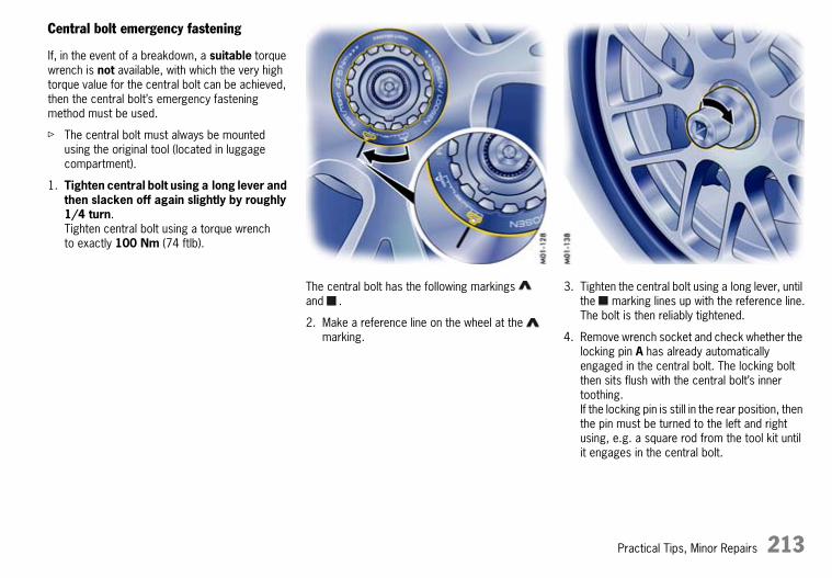
Practical Tips, Minor Repairs 213
Central bolt emergency fastening
If, in the event of a breakdown, a suitable torque wrench is not available, with which the very high torque value for the central bolt can be achieved, then the central bolt’s emergency fastening method must be used.
f The central bolt must always be mounted using the original tool (located in luggage compartment).
1. Tighten central bolt using a long lever and then slacken off again slightly by roughly 1/4 turn. Tighten central bolt using a torque wrench to exactly 100 Nm (74 ftlb).
The central bolt has the following markings and .
2. Make a reference line on the wheel at the marking.
3. Tighten the central bolt using a long lever, until the marking lines up with the reference line.The bolt is then reliably tightened.
4. Remove wrench socket and check whether the locking pin A has already automatically engaged in the central bolt. The locking bolt then sits flush with the central bolt’s inner toothing.If the locking pin is still in the rear position, then the pin must be turned to the left and right using, e.g. a square rod from the tool kit until it engages in the central bolt.
10_Turbo_20.book Seite 213 Freitag, 7. August 2009 12:55 12

214 Practical Tips, Minor Repairs
d Warning!
Risk of accidents and damage.
f Never drive off unless the locking pin is engaged.
5. Position the crest cover in the central bolt so that the position finger is located in the opening groove. Then push the cover into its seating.If necessary, apply a light coating of grease to the rubber ring beforehand.
6. Then you can lower the car.Please observe the chapter “CHANGING A WHEEL” on Page 207.
f Have the central bolt slackened off promptly by a qualified specialist workshop and then tightened again using a suitable torque wrench to the prescribed tightening torque of 500 Nm (370 ftlb).We recommend that you get a Porsche dealer to do this work as dealers have trained workshop personnel and the necessary parts and tools.
Rim cleaner
d Caution!
Using rim cleaners: Rim cleaners can be used for bleaching the central bolt’s anodised surfaces.
f Only use rim cleaners approved by Porsche and do so sparingly and in line with the instructions for use.
10_Turbo_20.book Seite 214 Freitag, 7. August 2009 12:55 12

Practical Tips, Minor Repairs 215
Flat Tyre1. Stop the vehicle as far away from the driving
lane as possible. The vehicle must be parked on a firm and flat surface offering adequate grip.
2. Switch on the hazard warning lights.
3. Apply the handbrake.
4. Shift into 1st gear or move the PDK selector lever to position P.
5. Straighten the front wheels.
6. Withdraw the ignition key to lock the steering and prevent the engine from being started.
7. Have any passengers leave the vehicle.
8. Set up a warning triangle at a suitable distance. A - Filler bottle
B - Filler hose
Tyre sealant
The tyre sealant can be used to seal small cuts, especially in the tyre tread.
Sealing the tyre with tyre sealant is only an emergency repair so that you can drive to the next workshop. Tyres repaired with sealant must be used only over short distances and in emergencies.
You can find tyre sealant and a compressor with pressure tester in the tool box in the luggage compartment.
The tyre sealant comprises:
– a filler bottle
– a filler hose
– a valve turner
– a spare valve insert and
– a sticker denoting the maximum permissible speed for the driver’s field of vision.
d Danger!
Risk of accident.
f Use the tyre sealant only in the case of cuts or punctures no larger than 4 mm.
f Never use the tyre sealant if the rim is damaged.
10_Turbo_20.book Seite 215 Freitag, 7. August 2009 12:55 12

216 Practical Tips, Minor Repairs
d Warning!
The sealant is highly flammable and harmful to health.
f Fire, naked flame and smoking are prohibited when handling tyre sealant.
f Avoid contact with skin, eyes or clothing.
f Keep tyre sealant away from children.
f Do not inhale vapours.
In case of contact with the sealant:
f If sealant gets on the skin or in the eyes, thoroughly rinse the affected part of the body off or out without delay.
f Change soiled clothing immediately.
f Visit a doctor immediately in the event of an allergic reaction.
f If sealant was swallowed, thoroughly rinse out the mouth without delay and drink plenty of water.Do not induce vomiting.See a doctor immediately.
A - Filler bottleB - Filler hoseC - Plug of the filler hoseD - Valve turnerE - Valve insertF - Tyre valve
Filling in sealant
1.Leave the object that caused the puncture in the tyre.
2.Remove compressor, sealant and the enclosed sticker from the luggage compartment.
3.Adhere the sticker in the driver’s field of vision.
4.Shake filler bottle A.
5.Screw filler hose B onto the filler bottle. The filler bottle is now open.
6.Unscrew valve cap from tyre valve F.
7.Remove valve insert E from the tyre valve with valve turner D.Keep the valve insert in a clean and dry place.
8.Remove plug C of filler hose B.
9.Push filler hose onto the tyre valve.
10.Hold filler bottle higher than the level of the tyre valve and squeeze it forcefully until the bottle is completely emptied into the tyre.
11.Pull filler hose off the tyre valve.
12.Twist the valve insert firmly into the tyre valve using the valve turner.
13.Connect the compressor to the cigarette lighter and inflate the tyre to at least 2.5 bar (36 psi). If this tyre inflation pressure cannot be reached, then the tyre is too badly damaged.Do not continue driving with this tyre.Screw valve cap onto the tyre valve.
14.Check the tyre pressure after driving for around 10 minutes.If the tyre pressure is less than 1.5 bar (22 psi), do not continue driving.If a value of more than 1.5 bar (22 psi) is indicated, correct the pressure to the prescribed value.
10_Turbo_20.book Seite 216 Freitag, 7. August 2009 12:55 12

Practical Tips, Minor Repairs 217
f Please observe the chapter “TYRE INFLATION PRESSURE FOR COLD TYRES (20 °C)” on Page 249.
15.Consult a qualified specialist workshop. We recommend a Porsche partner for this work as they have trained workshop personnel and the necessary parts and tools.
f Please also follow the separate instructions for using the tyre sealant.
Note on operation for vehicles with Tyre Pressure Monitoring
f On vehicles with Tyre Pressure Monitoring, the settings on the on-board computer must be updated after the wheel change.
f Please observe the chapter “TPM TYRE PRESSURE MONITORING” on Page 119.
Care instructions
After drying, any sealant that emerges can be peeled off like a film.
d Warning!
Risk of accident.
f Have tyre replaced by a specialist workshop as soon as possible. Inform the specialist workshop that the tyre contains sealant.
f Avoid hard acceleration and high cornering speeds.
f Observe maximum speed of80 km/h (50 mph).
f Please always observe the safety and operating instructions, which can be found in the separate operating instructions for the sealant and on the compressor.
10_Turbo_20.book Seite 217 Freitag, 7. August 2009 12:55 12

218 Practical Tips, Minor Repairs
Lifting the vehicle with a lifting platform, trolley jack or standard jack
f The car must be raised only at the illustrated jacking points.
f Before driving onto a lifting platform, ensure that there is sufficient space between the lifting platform and the vehicle.
f In order to avoid serious damage, never jack up the vehicle at the engine, transmission or at the axles.
10_Turbo_20.book Seite 218 Freitag, 7. August 2009 12:55 12

Practical Tips, Minor Repairs 219
Electrical SystemIn order to avoid damage and faults in electrical or electronic systems, work on the electrical system should be performed by a qualified specialist workshop. We recommend that you use a Porsche partner for this work since these are staffed with trained personnel and have the necessary parts and tools.
f Use only accessories authorised by Porsche.
d Warning!
Risk of short circuit and fire.
f Disconnect the negative terminal on the battery during all work on the electrical system.
Relays
Relays should be checked or changed only by an authorised workshop.
In oddments tray between the front seats
Socket
Electrical accessories should only be connected to the 12 V socket.
The cigarette lighter should not be used for electrical accessories (except for the tyre filling compressor).
The socket can be located either in the oddments tray or in the front passenger footwell, depending on vehicle equipment.
f Please observe the maximum power consumption.
Front passenger footwell
The maximum power consumption of the socket is 70 W.
Note on operation
The tyre filling compressor must be connected to the cigarette lighter.
The socket and thus the connected electrical accessories function even if the ignition is switched off or the ignition key is withdrawn.
If the engine is not running and the accessories are switched on, the vehicle battery will be discharged.
10_Turbo_20.book Seite 219 Freitag, 7. August 2009 12:55 12

220 Practical Tips, Minor Repairs
Do not operate additional accessories for more than 5 minutes when engine is off.
f Please observe the power specifications from the accessory manufacturer.
Alarm system, central locking
The status of the central locking and alarm system is not changed by disconnecting the battery.When the battery is disconnected, the alarm system ceases to function.
Central locking overload protection
If the central locking system is operated more than ten times within a minute, further operation is blocked for 30 seconds.
Load switch-off after 2 hours or 7 days
When the ignition key is removed, loads which are switched on or are in standby mode (e.g. luggage compartment illumination, interior light) are automatically switched off after approx. 2 hours.The PCM switches off after approx. 10 minutes.
If the vehicle is not started or unlocked with the remote control within 7 days, the remote control standby function is switched off (to save the vehicle battery).
1. In this case, unlock the driver’s door with the key at the door lock.Leave the door closed in order to prevent the alarm system from being triggered.
2. Press button 1 on the remote control.
The remote control is now activated again.
10_Turbo_20.book Seite 220 Freitag, 7. August 2009 12:55 12

Practical Tips, Minor Repairs 221
Changing fuses
In order to prevent damage to the electrical system due to short circuits and overloads, the individual circuits are protected by fuses.The fuse box is located in the driver’s footwell.
A - Plastic gripperB - Spare fuses
1. Switch off the load with the defective fuse.
2. Pull off plastic cover at the finger hole (arrow).The fuse plan and instructions for emergency unlocking of the luggage compartment lid can be found on the inner side of the cover.
3. Remove the corresponding fuse from its slot using the plastic gripper A in order to check it.A blown fuse can be identified by the melted metal strip.
4. Replace only with fuses with the same rated current. We recommend that you use genuine Porsche fuses for replacement.
Note
f If a fuse blows repeatedly:Consult a qualified specialist workshop. We recommend a Porsche partner for this work as they have trained workshop personnel and the necessary parts and tools.
10_Turbo_20.book Seite 221 Freitag, 7. August 2009 12:55 12

222 Practical Tips, Minor Repairs
Emergency unlocking of luggage compartment lid
If the battery is discharged, the luggage compartment lid can be opened only with the aid of a donor battery.
Note
The engine cannot be started with this method.
f Please observe the chapter “JUMP LEAD STARTING” on Page 228.
Unlocking lids
1. Use the key to unlock the vehicle at the door lock.
2. Remove the plastic cover from the fuse box.
3. Pull out positive terminal C (red) in the fuse box using the plastic gripper A (yellow).
A - Plastic gripper (yellow)C - Positive terminal (red)
4. Use a jump lead to connect the positive terminal of the spare battery to the positive terminal A in the fuse box.
Note
If the vehicle was locked, the alarm horn will sound when the negative lead is connected.
5. Use the black jump lead to connect the negative terminal of the donor battery to the door arrester D.
6. Press button 2 on the remote control for approx. 2 seconds to unlock the luggage compartment lid. The alarm system is switched off.
7. Disconnect the negative lead first, then the positive lead.
8. Push in positive terminal C in the fuse box and fit the plastic fuse box cover.
10_Turbo_20.book Seite 222 Freitag, 7. August 2009 12:55 12

Practical Tips, Minor Repairs 223
BatteryThe battery is located in the luggage compartment under a black plastic cover.
f Please observe the chapter “REMOVING THE BATTERY” on Page 226.
f Please observe the chapter “EMERGENCY OPERATION – RELEASING THE IGNITION KEY” on Page 60.
d Warning!
Risk of short circuit, fire and damage to generator and electronic control units.
f Disconnect the negative terminal on the battery during all work on the electrical system.
f Ensure that tools or conductive jewellery (rings, chains, watch straps) do not come into contact with live parts of the vehicle.
Danger of explosion as a result of static charge.
f Do not wipe battery with a dry cloth.
f Eliminate potential electrostatic charge by touching the vehicle before touching the battery.
Heed warnings on the battery
Read the operating instructions
Wear eye protection
Keep children away
Danger of explosionWhile the battery is being charged, a highly explosive gas mixture is formed, so:
Fire, sparks, naked flames and smoking are prohibitedAvoid causing sparks and short circuits when handling cables and electrical equipment.In the case of batteries with central venting, there is a greater concentration of explosive gas at the hose opening. The gas-venting hose must not be kinked or blocked with dirt.
Danger of caustic burnsBattery acid is highly caustic, so: wear safety gloves and eye protection.Do not tip the battery, or acid may spill from the venting aperture.
First aidIf acid splashes into an eye, immediately rinse with clean water for a few minutes.See a doctor immediately.If acid splashes onto skin or clothing, neutralise immediately with soapsuds and rinse with plenty of water.If you accidentally drink acid, consult a doctor immediately.
DisposalHand in the old battery at a battery collection point.
Never dispose of an old battery with domestic waste.
10_Turbo_20.book Seite 223 Freitag, 7. August 2009 12:55 12

224 Practical Tips, Minor Repairs
Charge state
A well-charged battery prevents starting problems and has a longer service life.Traffic density, requirements regarding noise, exhaust gas and fuel consumption reduce the engine speed and, hence, the generator output.However, the large number of electrical loads has markedly increased the demand for electrical power.
In order to avoid unintended battery discharge:
f Switch off unnecessary electrical loads in city traffic, on short trips and in queues.
f Always withdraw the ignition key when leaving the vehicle.
f Avoid frequent operation of the convertible top and operation of the Porsche Communication Management system and audio system when the engine is not running.
In the cold season in particular or if the vehicle is used primarily for short journeys, it may be necessary to recharge the battery from time to time.
Battery care
f Keep battery surface clean and dry.
f Ensure that the cell plugs, vent hose and terminal clamps are firmly secured.
Checking acid level
The acid level should be checked more frequently by a qualified specialist workshop during the summer months and in predominantly warm countries.
Charging the battery
Your Porsche partner will be pleased to advise you about a suitable charger.
1. Always observe the instructions of the charger manufacturer. Depending on the type of charger, the battery may have to be disconnected. Important: in this case, disconnect the negative lead first, and then the positive lead – danger of short circuit! Reconnection must be carried out in reverse order.
2. Before charging, cold batteries must be warmed up indoors.
3. Frozen batteries must be thawed out before being charged.
4. When charging, ensure that there is adequate ventilation.
5. Connect the charger to the battery.Only plug into the mains and switch the charger on when it has been correctly connected up.
6. Switch on the charger.
7. After charging, switch off the charger first and then disconnect it.
f Please observe the chapter “PUTTING VEHICLE INTO OPERATION” on Page 225.
Winter driving
The ability of the battery to deliver and store power decreases at low outside temperatures. Moreover, the battery is more heavily loaded in the winter months by the heated rear window, more frequent use of additional lights, the blower and the windscreen wipers, etc.
f Have the battery checked before the start of winter.
Maintenance note
Keep the battery well charged to prevent it from freezing.
A discharged battery can freeze even at –5 °C, but a fully charged one only freezes at –40 °C.
f A frozen battery must always be thawed before connecting jump leads.
10_Turbo_20.book Seite 224 Freitag, 7. August 2009 12:55 12

Practical Tips, Minor Repairs 225
Laying up the vehicle
If the vehicle stands for long periods in the garage or workshop, the doors and lids should be closed.
f Please observe the chapter “EMERGENCY UNLOCKING OF LUGGAGE COMPARTMENT LID” on Page 222.
f Withdraw the ignition key and, if necessary, disconnect the battery.When the battery is disconnected, the alarm system ceases to function!
Even if you put your vehicle out of operation, the battery still discharges.
f The battery must be charged, i.e. connected to a charger, approximately every 6 weeks in order to preserve functioning. Always observe the instructions of the charger manufacturer.
f Store a battery that has been removed in a dark, cool place, but not subject to frost.
Replacing the battery
The battery is subject to normal wear: its service life depends heavily on the care you give it, climatic conditions and the conditions of use (distances, loads).
It is not possible to use the details on the battery case to determine a comparable battery that meets all the specific requirements of Porsche.
f Only replace the battery with one that satisfies the specific requirements of your vehicle. We recommend that you use a genuine Porsche battery.
f Please observe the disposal instructions for batteries!
Putting vehicle into operation
After the battery is connected or after an exhaustively discharged battery is charged, the PSM multifunctional light lights up on the instrument panel and a message appears on the on-board computer to indicate a fault.
This fault can be remedied with a few simple steps:
1. Start the engine.
2. With the vehicle stationary, perform a few steering movements to the left and right and then drive a short distance in a straight line until the PSM multifunctional light goes out and the message on the on-board computer disappears.
3. If the warnings do not disappear, then:Drive carefully to the nearest qualified specialist workshop.Have the fault remedied.
4. After the warnings disappear:Stop the vehicle in a suitable place.
5. Perform adaptation of the power windows:Close the windows once with the rocker switch.Press rocker switch upwards again to store the final position of the windows in the control unit.
10_Turbo_20.book Seite 225 Freitag, 7. August 2009 12:55 12

226 Practical Tips, Minor Repairs
Removing the battery
The battery is located in the luggage compartment under a black plastic cover.
1. Switch off engine and all electrical loads.
2. Open turn-locks A.Remove plastic cover.
3. Pull off vent hose C.
4. Important: disconnect the negative lead first, and then the positive lead – danger of short circuit!
5. Unscrew fastening screw B.
6. Remove the battery.
d Warning!
Risk of damage to generator and electronic control units.
f Do not disconnect battery while the engine is running.
Risk of caustic burns from escaping acid.
f Do not tilt the battery when removing it.
Installing the battery
1. Insert battery and push it all the way to the stop.
2. Turn in fastening screw B.
3. Important: connect the positive lead first, and then the negative lead – risk of short circuit!
4. Push on vent hose C.
10_Turbo_20.book Seite 226 Freitag, 7. August 2009 12:55 12
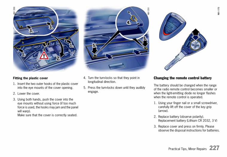
Practical Tips, Minor Repairs 227
Fitting the plastic cover
1. Insert the two outer hooks of the plastic cover into the eye mounts of the cover opening.
2. Lower the cover.
3. Using both hands, push the cover into the eye mounts without using force (if too much force is used, the hooks may jam and the panel will warp).Make sure that the cover is correctly seated.
4. Turn the turn-locks so that they point in longitudinal direction.
5. Press the turn-locks down until they audibly engage.
Changing the remote control battery
The battery should be changed when the range of the radio remote control becomes smaller or when the light-emitting diode no longer flashes when the remote control is operated.
1. Using your finger nail or a small screwdriver, carefully lift off the cover of the key grip (arrow).
2. Replace battery (observe polarity).Replacement battery (Lithium CR 2032, 3 V)
3. Replace cover and press on firmly. Please observe the disposal instructions for batteries.
10_Turbo_20.book Seite 227 Freitag, 7. August 2009 12:55 12

228 Practical Tips, Minor Repairs
Jump Lead Startingf Please observe the chapter “EMERGENCY
UNLOCKING OF LUGGAGE COMPARTMENT LID” on Page 222.
f Please observe the chapter “BATTERY” on Page 223.
If the battery is flat, the battery of another vehicle can be used to start the car with the aid of jump leads.Both batteries must be 12 V types. The capacity (Ampere hours, Ah) of the donor battery must not be substantially less than that of the discharged battery.The discharged battery must be correctly connected to the vehicle’s electrical system.
d Warning!
Risk of damage and injury due to short circuit.
f Use only standard jump leads with sufficient cross section and completely insulated clamps.Follow the jump lead manufacturer’s instructions.
f Route the jump leads so that they cannot be caught by moving parts in the engine compartment.The vehicles must not be in contact, otherwise current might flow as soon as the positive terminals are connected.
f Carefully ensure that conductive jewellery (rings, chains, watch straps) does not come into contact with live parts of the vehicle.
Risk of caustic burns from escaping acid.
f Do not lean over the battery.
Danger of gas explosion.
f Keep sources of ignition away from the battery, e.g. naked flame, burning cigarettes or sparks due to cable contact.
f Before connecting jump leads, it is essential to thaw out a frozen battery.
Connecting jump leads
Always observe the sequence below:
1. Connect the positive lead (red) to the positive terminal of the discharged battery first, then connect it to the positive terminal of the donor battery.
2. First connect the negative cable (black) to the negative terminal of the donor battery, then connect it to a suitable grounding point on the vehicle with the discharged battery. This grounding point must be as far as possible from the battery.For example, a solid metal part is a suitable grounding point.
If no suitable grounding points are to be found on either vehicle, the negative lead must carefully be connected directly to the negative terminal of the battery.
If a suitable grounding point is to be found only on the donor vehicle, the negative lead must first be connected to the terminal of the discharged battery, then to the grounding point of the donor vehicle.
3. Run the engine of the donor vehicle at a higher speed.
4. Start the engine.An attempted start using jump leads should not last more than 15 seconds. Then allow a waiting period of at least one minute.
5. NoteBefore disconnecting the jump leads, electrical loads on the vehicle with the discharged battery, such as the heated rear window and the heating fan blower, should be switched on (the vehicle’s lights must not be switched on). This reduces voltage peaks which may occur when disconnecting the jump leads.
With the engine running, remove both jump leads in reverse order.
10_Turbo_20.book Seite 228 Freitag, 7. August 2009 12:55 12

Controls, Safety, Instruments 229
Bulb chart
Type, rating
Dipped beam headlight Philips, D2S 35W
Additional high beam headlight without cornering light H11 LL, 55W
Additional high beam headlight with cornering light H7 LL, 55W
Side lights, front WY5W BV
Direction indicator light, side WY5W
Number plate light C5W
Replacing Bulbs
d Warning!
Danger of short circuit.
f Always switch off the relevant load when changing bulbs.
Risk of injury. The Bi-Xenon headlights are under high voltage when installed.
f Exercise extreme caution when working in the area of the Bi-Xenon headlights.
Risk of damage. Bulbs of a higher wattage can damage the lamp housing.
f Only use the bulbs specified in the bulb chart.
f Bulbs must be clean and free from grease.
f Never touch bulbs with your bare hands.Use a cloth or soft paper when replacing bulbs.
f Always carry spare bulbs with you.In certain countries, the carrying of spare bulbs is mandatory.
10_Turbo_20.book Seite 229 Freitag, 7. August 2009 12:55 12

230 Practical Tips, Minor Repairs
Headlights
d Caution!
Risk of damage to headlights due to abrasion and excessive temperatures.
f Do not affix any coverings (e.g. “stone guards” or films) in the area of the headlights.
Note
The headlights may mist up due to temperature and humidity.
f To ensure optimum ventilation, do not cover the gap between headlight and body (e.g. “stone guards” or films).
Removing headlights
1. Unscrew plastic nut A.Detach side carpeting.
2. Remove rubber plug B from the unlocking opening.
10_Turbo_20.book Seite 230 Freitag, 7. August 2009 12:55 12

Practical Tips, Minor Repairs 231
3. Place socket wrench (tool kit) on the unlocking spindle.The handle of the wrench should point horizontally to the rear.
4. Turn socket wrench approx. 180° A. The headlight is unlocked and pushed forward slightly during this process.
5. Turn socket wrench back until it is pointing vertically downward B and leave in position.
6. The headlight is now unlocked and can be pulled forward out of the wing.
Installing
1. Insert headlight into the guide rails and push fully into the wing.
2. Push headlight to the rear and at the same time turn the socket wrench until it points horizontally to the rear C.The headlight locking device must perceptibly and audibly engage.
3. Insert rubber plug into the unlocking opening and secure the carpeting.Check the function of all lights.
Dipped beam, high beam and additional high beam
Opening the lid of the headlight housing
1. Unscrew the 4 screws A.
2. First lift release tab B, then push both release tabs C upwards and take off lid.
10_Turbo_20.book Seite 231 Freitag, 7. August 2009 12:55 12

232 Practical Tips, Minor Repairs
Changing bulb for dipped beam and high beam (without cornering light)
1. Turn the plug anti-clockwise (bayonet lock) and pull it off.
2. Disengage both fixing clips A.
3. Replace defective bulb B.When doing so, ensure bulb is seated properly.
4. Engage both fixing clips A, push on plug and turn right as far as the stop.
10_Turbo_20.book Seite 232 Freitag, 7. August 2009 12:55 12

Practical Tips, Minor Repairs 233
Changing bulb for auxiliary main beam(without cornering light)
1. Turn the bulb holder.Turn it anti-clockwise on the left headlight and clockwise on the right headlight.Take bulb holder out of the headlight housing.
2. Pull both plug release tabs apart.Pull plug out of the bulb holder.
3. Replace the defective bulb with bulb holder.
4. Reassemble in reverse order.
Closing cover of the headlight housing
1. Push on cover until it perceptibly engages.
2. Fasten cover with the 4 screws.
10_Turbo_20.book Seite 233 Freitag, 7. August 2009 12:55 12

234 Practical Tips, Minor Repairs
Changing bulb for dipped beam and high beam (with cornering light)
1. Undo the 3 screws on the control unit and remove the control unit.
2. Turn the plug anti-clockwise and pull it off. 3. Disengage both fixing clips.
4. Replace defective bulb.When doing so, ensure bulb is seated properly.
5. Engage both fixing clips, push on plug and turn clockwise as far as it will go.
6. Fit control unit and screw tight.
7. Push on housing cover until it perceptibly engages.
8. Fasten housing cover with the 4 screws.
10_Turbo_20.book Seite 234 Freitag, 7. August 2009 12:55 12
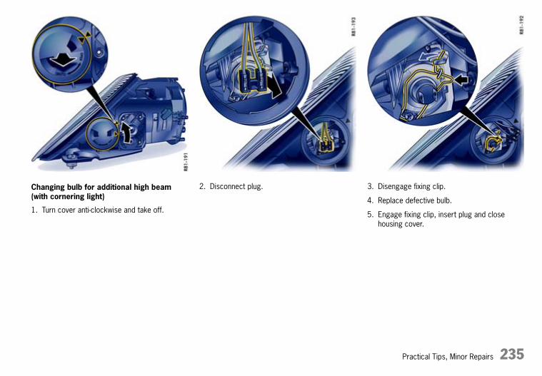
Practical Tips, Minor Repairs 235
Changing bulb for additional high beam (with cornering light)
1. Turn cover anti-clockwise and take off.
2. Disconnect plug. 3. Disengage fixing clip.
4. Replace defective bulb.
5. Engage fixing clip, insert plug and close housing cover.
10_Turbo_20.book Seite 235 Freitag, 7. August 2009 12:55 12

236 Practical Tips, Minor Repairs
Changing bulb for side light
1. Undo fastening screw.
2. Slide light housing slightly to outside of vehicle and then remove to the front.
3. Turn holder towards the left and pull it out to the rear.
4. Pull out and replace defective bulb.
5. Push holder back in and turn towards the right.
6. Insert lamp housing first at the outside of the car and then slide in the guide towards the vehicle centre.
7. Tighten fastening screw.
8. Check operation of the light.
10_Turbo_20.book Seite 236 Freitag, 7. August 2009 12:55 12

Practical Tips, Minor Repairs 237
Changing bulb for side direction indicator light
1. Remove cap in the wheel housing liner with the screwdriver.
2. Insert the screwdriver into the opening in the wheel housing liner parallel to the indicator light (in driving direction).By pressing with the screwdriver, disengage the securing spring of the direction indicator housing.
3. Remove indicator light and undo bulb holder (bayonet lock).
4. Remove the bulb from the holder and replace it. Insert holder.Check operation of the light.
5. Insert the direction indicator’s retaining lugs A into the side section at the front.Push in direction indicator until the securing spring B is felt to engage.
6. Press cap into the wheel housing liner.
10_Turbo_20.book Seite 237 Freitag, 7. August 2009 12:55 12

238 Practical Tips, Minor Repairs
Number Plate Light
Changing bulb
1. Unscrew both screws A and remove the light lens.
2. Remove defective bulb from between the contact springs and replace.
3. Reassemble in reverse order.Check operation of the light.
Changing Light-Emitting Diodes and Long-Life BulbsThe following lights are equipped with light-emitting diodes (LEDs) or long-life bulbs and cannot be replaced individually. Replacement also involves a greater amount of installation work:
– daytime driving lights,
– tail lights and
– additional brake lights.
f Have the defective light replaced at a qualified specialist workshop. We recommend a Porsche partner for this work as they have trained workshop personnel and the necessary parts and tools.
10_Turbo_20.book Seite 238 Freitag, 7. August 2009 12:55 12

Practical Tips, Minor Repairs 239
Changing headlights from left to right-hand trafficIf you travel to a country where traffic uses the other side of the road, the headlights must be repositioned when you cross the border.The dipped beam then lights symmetrically and drivers of oncoming vehicles are not dazzled.
On the return journey, do not forget to return the headlights to the “0” position.
Headlights without cornering light
Repositioning headlights
1. Remove headlight and open housing cover (additionally remove the control unit for headlights with cornering light).Please observe the chapter “REMOVING HEADLIGHTS” on Page 230.
2. Set lever to position “T”.
3. Install the control unit in the case of headlights with cornering light.
4. Close the cover of the headlight housing and install headlight.
Headlight with cornering light
5. Reposition the other headlight.
10_Turbo_20.book Seite 239 Freitag, 7. August 2009 12:55 12

240 Practical Tips, Minor Repairs
Headlight adjustmentAdjustment of the headlights should only be performed in a specialist workshop with suitable adjustment equipment.The adjustment is made with the vehicle ready to drive and the fuel tank completely filled.
f Check tyre pressure and adjust if necessary.Please observe the chapter “TECHNICAL DATA” on Page 246.
f Load the driver’s seat with a person or a 75 kg weight.After loading the vehicle, roll it a few metres so that the suspension can settle.
Adjustment screws
1. Unscrew the plastic nut A and detach side carpeting in the luggage compartment.
C - Lateral adjustment B - Height adjustment
1. Open up the cover to the relevant adjustment screw.
2. Turn the hexagon socket screw to the right or left.This changes the headlight adjustment accordingly.
10_Turbo_20.book Seite 240 Freitag, 7. August 2009 12:55 12

Practical Tips, Minor Repairs 241
Towing and Tow-Starting
d Warning!
Risk of accident. No servo assistance is available on the towed vehicle when its engine is not running. Greater force is therefore necessary when braking and steering.The ABS and PSM do not operate if this is the case.
f Exercise great care when on tow.
f Vehicles with defective brakes must not be towed.
f Switch on the ignition so that the brake lights and direction indicator lights operate and the steering lock cannot engage.
f Always keep the towing rope taut when towing. Avoid jerky, sudden loads.
f Always observe the laws governing towing and tow-starting.
d Caution!
Risk of damage when towing due to small ground clearance.
f When towing and when recovering with a towing vehicle, pay attention to the small ground clearance.
Tow-starting
If the battery is defective or completely discharged, the engine can be started only by changing the battery or by using jump leads.
f Please observe the chapter “JUMP LEAD STARTING” on Page 228.
Cars fitted with a catalytic converter may only be tow-started when the engine is cold.If the engine is warm, unburned fuel could damage the catalytic converter.
Vehicles with PDK transmission
The vehicle cannot be tow-started, nor should this be attempted due to the risk of serious transmission damage.
Towing
When being towed, the vehicle must have all four wheels on the ground or it must be moved on a car transporter or a trailer. Any raising of an axle, irrespective of whether at the front or rear, is only permissible if the drive shaft (cardan shaft) has been removed beforehand. The ignition must be switched off.
Vehicles with PDK transmission
When the engine is not running, adequate lubrication of the transmission is not guaranteed. Observe the following points to avoid damage to the transmission:
f Select position N.
f Do not exceed a maximum speed of 50 km/h (30 mph). Maximum towing distance: 50 km (30 miles).
10_Turbo_20.book Seite 241 Freitag, 7. August 2009 12:55 12

242 Practical Tips, Minor Repairs
PDK selector lever emergency release
In the event of an electronics failure, the selector lever must be released for towing.
1. Lift up the rubber mat in the oddments tray.
2. Insert a screwdriver in the opening and press down until you feel it reach the limit position. The selector lever can now be moved to position N.
Fitting towing lug
The towing lug A is stored in the tool box in the luggage compartment.
1. Press the lower edge of the appropriate plastic cover into the bumper until the cover disengages.
2. Pull cover out of the bumper and let it hang by its thread.
3. Completely screw in the towing lug.
Removing the towing lug
1. Unscrew the towing lug A.
2. Insert plastic cover at the lower edge of the opening.
3. Fold the cover up and press on its upper edge to engage it in the bumper.
10_Turbo_20.book Seite 242 Freitag, 7. August 2009 12:55 12

Vehicle Identification, Technical Data 243
Vehicle Identification, Technical DataVehicle Identification Data ........................... 244Technical Data ........................................... 246Index......................................................... 252
10_Turbo_20.book Seite 243 Freitag, 7. August 2009 12:55 12

244 Vehicle Identification, Technical Data
Vehicle Identification Dataf When ordering spare parts or making inquiries,
please always quote the vehicle identification number.
Vehicle data carrier
The vehicle data bank is attached to the inside of the “Guarantee and Maintenance” booklet.It contains all important data about your vehicle.
Note
The data bank cannot be re-ordered if it is lost or damaged.
Vehicle identification number
The vehicle identification number is in the luggage compartment under the battery cover and at the bottom left behind the windscreen.
Removing the battery cover
f Please observe the chapter “REMOVING THE BATTERY” on Page 226.
10_Turbo_20.book Seite 244 Freitag, 7. August 2009 12:55 12
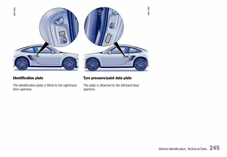
Vehicle Identification, Technical Data 245
Identification plate
The identification plate is fitted to the right-hand door aperture.
Tyre pressure/paint data plate
The plate is attached to the left-hand door aperture.
10_Turbo_20.book Seite 245 Freitag, 7. August 2009 12:55 12

246 Vehicle Identification, Technical Data
Technical Data
Engine data
Engine type MA 170Type Horizontally opposed-cylinder engine, liquid cooledNumber of cylinders 6Bore 102 mmStroke 77.5 mmDisplacement 3,800 cm3
Engine output as per EU 368 kW (500 HP)at crankshaft speed 6,000 rpmTorque as per EU 650 Nm (479 ftlb.) (overboost 700 Nm (516 ftlb.))at crankshaft speed 1,950–5,000 rpm (overboost 2,000–4,500 rpm)Engine oil consumption up to 1.5 l/1,000 kmMaximum permitted engine speed 7,000 rpm
10_Turbo_20.book Seite 246 Freitag, 7. August 2009 12:55 12

Vehicle Identification, Technical Data 247
Fuel consumption and emission
Measuring method as per Euro 5: The data was determined using the measuring method Euro 5 No. 692/2008/EC in the NEDC (New European Driving Cycle) with standard vehicle equipment. The information does not refer to an individual vehicle and does not form part of the product offering. The information serves solely to permit comparison of the different vehicle types. Further information on the individual vehicles is available from your Porsche partner.
Measuring method as per Euro 4 (values in brackets): determined according to 80/1268/EEC as amended.
Engine type Urban Extra- Combined Combinedurban CO2
(l/100 km) (l/100 km) (l/100 km) (g/km)
Manual transmission, Coupé MA 170 17.3 (17.0) 8.3 (8.1) 11.6 (11.4) 272 (272)PDK transmission, Coupé MA 170 17.0 (16.8) 8.1 (8.0) 11.4 (11.2) 268 (268)Manual transmission, Cabriolet MA 170 17.5 (17.2) 8.3 (8.2) 11.7 (11.5) 275 (275)PDK transmission, Cabriolet MA 170 17.2 (16.9) 8.2 (8.0) 11.5 (11.3) 270 (270)
10_Turbo_20.book Seite 247 Freitag, 7. August 2009 12:55 12

248 Vehicle Identification, Technical Data
Tyres, rims, tracks
Tyres Wheel Rim offset Track
Summer tyres front 235/35 ZR 19 (87Y) 8.5 J x 19 H2 56 mm 1,490 mmrear 305/30 ZR 19 (102Y) XL 11 J x 19 H2 51 mm 1,548 mm
Winter tyres front 235/40 R 18 91V M+S 8 J x 18 H2 57 mm 1,488 mmrear 295/35 R 18 99V M+S 1) 11 J x 18 H2 51 mm 1,548 mm
or front 235/35 R 19 87V M+S 8.5 J x 19 H2 56 mm 1,490 mmrear 295/30 R 19 100V XL M+S 1) 11 J x 19 H2 51 mm 1,548 mm
The load capacity coefficient (e.g. “91”) and maximum speed code letter (e.g. “Y”) for permitted top speed are minimum requirements. When fitting new tyres or changing tyres: Please observe the chapter “TYRES AND WHEELS” on Page 201.
Tyre and rim sizes Approval for tyre and rim sizes is granted on the basis of extensive testing. Your Porsche partner will be pleased to advise you about the current approval status. If you refit your vehicle with tyres and/or wheels not authorised by Porsche, this may have a dangerous effect on driving stability.
Snow chains Snow chain clearance can only be guaranteed with tyres marked 1). Can only be mounted on the rear wheels; maximum permissible speed is 50 km/h (30 mph). Only use Porsche-approved fine-link cross-type or edge chains.
10_Turbo_20.book Seite 248 Freitag, 7. August 2009 12:55 12

Vehicle Identification, Technical Data 249
Tyre inflation pressure for cold tyres (20 °C)
Summer and winter tyres
These tyre inflation pressures apply only to the tyre makes and types approved by Porsche.
f Please observe the chapter “TYRES AND WHEELS” on Page 201.
f Please observe the chapter “TPM TYRE PRESSURE MONITORING” on Page 119.
Capacities
Use only fluids and fuels approved by Porsche. Your Porsche partner will be pleased to advise you.
18 inch and 19 inch wheels, partially loaded front 2.3 bar (34 psi)(up to 2 persons without luggage) rear 2.7 bar (40 psi)
18 inch and 19 inch wheels, fully loaded front 2.5 bar (37 psi)(2 or more persons with luggage) rear 3.0 bar (44 psi)
Engine Oil change quantity with/without oil filter approx. 7.5 litres Please observe the chapter “ENGINE OIL LEVEL” on Page 182.
Fuel tank refill capacity Left-hand drive vehicles: approx. 67 litres, including approx. 12 litres reserveRight-hand drive vehicles: approx. 66 litres, including approx. 12 litres reserve
Fuel quality The engine is designed to provide optimum performance and fuel consumption if unleaded premium fuel with 98 RON/88 MON is used. If unleaded premium fuels with octane numbers of at least 95 RON/85 MON are used, the engine’s knock control automatically adapts the ignition timing.
Windscreen washer system Approx. 6 litres with headlight washer
10_Turbo_20.book Seite 249 Freitag, 7. August 2009 12:55 12

250 Vehicle Identification, Technical Data
Weights
1) Empty weight includes 75 kg driver and baggage share.2) The maximum gross weight must not be exceeded. Note: If additional accessories are installed, the available load capacity will be correspondingly less.3) Only use Roof Transport Systems from the Porsche Tequipment product range for your car or Roof Transport Systems that have been tested and approved
by Porsche.
Coupé Manual transmission PDK transmission
Empty weight (depending on equipment)per DIN 70020 1,570 kg 1,595 kgper 70/156/EEC 1) 1,645 kg 1,670 kgMaximum gross weight 1,935 kg 1,960 kgMaximum axle load, front 2) 825 kg 825 kgMaximum axle load, rear 2) 1,180 kg 1,200 kgMaximum load, roof transport system 3) 75 kg 75 kg
Cabriolet Manual transmission PDK transmission
Empty weight (depending on equipment)per DIN 70020 1,645 kg 1,670 kgper 70/156/EEC 1) 1,715 kg 1,745 kgMaximum gross weight 1,995 kg 2,020 kgMaximum axle load, front 2) 825 kg 825 kgMaximum axle load, rear 2) 1,220 kg 1,240 kg
10_Turbo_20.book Seite 250 Freitag, 7. August 2009 12:55 12

Vehicle Identification, Technical Data 251
Driving performance
Driving performance at DIN empty weight and half load, without performance-inhibiting additional equipment (e.g. special tyres)
Dimensions
Coupé Manual transmission PDK transmission
Maximum speed 312 km/h (195 mph) 312 km/h (195 mph)Acceleration 0–100 km/h (62 mph) 3.7 seconds 3.6 seconds Acceleration 0–100 km/h (62 mph) with Sport 3.6 secondsAcceleration 0–100 km/h (62 mph) with Sport + 3.4 seconds
Cabriolet Manual transmission PDK transmission
Maximum speed 312 km/h (195 mph) 312 km/h (195 mph) Acceleration 0–100 km/h (62 mph) 3.8 seconds 3.7 seconds Acceleration 0–100 km/h (62 mph) with Sport 3.7 secondsAcceleration 0–100 km/h (62 mph) with Sport + 3.5 seconds
Coupé CabrioletLength 4,450 mmWidth with external mirrors 1,952 mmWidth without door mirrors 1,852 mmHeight 1,300 mmWheelbase 2,350 mmGround clearance at maximum gross weight 107 mm 105 mmTurning circle 10.9 m
10_Turbo_20.book Seite 251 Freitag, 7. August 2009 12:55 12

252 Index
Index
AABS (anti-lock brake system)..........................46
Warning light ........................................46Air cleaner .................................................191Air distribution, automatic air-conditioning system ..................84Airbag systems ............................................40
Switching off passenger airbag ..............38Warning light ..................................41, 42
Air-conditioning compressorNotes...................................................86Switching on/off ...................................85
Alarm system ...............................................17Not active ..........................................220Switching off the alarm system ..............17Switching off the passenger compartment monitoring system............17
Alcantara, care of .......................................198All-wheel drive...............................................52Antenna .......................................................77Anti-lock brake system (ABS) .........................46Ashtray ........................................................72Auto-button air conditioning ...........................84Automatic air-conditioning system ..................84
Adjusting blower speed .........................85Air distribution ......................................86Automatic mode ...................................84Circulating-air mode ..............................85Defrosting the windscreen .....................85Setting temperature ..............................84Switching compressor on/off.................85
Automatic anti-dazzle function........................21
Automatic door locking............................13, 15Automatic transmission ...............................146Automatic window lowering............................19AUX .............................................................78Average consumption
Display on on-board computer..............103Information on on-board computer functions .............................132
Average speedDisplay on on-board computer..............103Information on on-board computer functions .............................132
BBackrest
Adjustment ...........................................23Release ................................................23
Battery.......................................................223Battery charge indicator ......................100Care ..................................................224Changing in vehicle key .......................227Charge state.......................................224Putting vehicle into operation ...............225Removing/installing .............................226Replacing ...........................................225Warning light.......................................100
Battery charge indicator ..............................100Warning light.......................................100
Before driving off ............................................6Belts ....................................................34, 198
Adjusting belt height ..............................35
Belt tensioner .......................................34Cleaning belts .......................................35Fastening..............................................35Height adjustment .................................35Releasing the seat belt ..........................35Warning light.........................................34
Blower setting, automatic air-conditioning system...................85Brake
Handbrake warning light.........................43Brake discs ....................................................3Brake fluid ......................................................3Brake light ..................................................238Brake light, additional ..................................238Brake pads.....................................................3Brakes .......................................................184
ABS Brake System ................................46Bedding in new brake pads ......................6Brake distribution warning light.............184Brake pad warning light .........................45Checking fluid level..............................184Fluid warning light................................185Footbrake.............................................44Handbrake ............................................43Parking brake .......................................43Test stand ................................45, 51, 53Warning light.......................................101Wear indication, brake pads ...................45
Bucket seat ..................................................25Bulbs
Chart..................................................229Replacing ...........................................229
10_Turbo_20.book Seite 252 Freitag, 7. August 2009 12:55 12

Index 253
CCabriolet ....................................................158
Closing the convertible top ..................160Convertible top care............................193Emergency operation of convertible top................................161Hardtop..............................................172Opening the convertible top .................159Windstop............................................168
Capacities, overview ...................................249Car care ....................................................192Car telephone...............................................77Care ..........................................................192Carpet .......................................................198Catalytic converter......................................188Central locking .....................................13, 220Central locking wheel ..................................209Central warning light ...................................101Centre vent, automatic air-conditioning system ..................87Changing a central locking wheel .................209Changing fuses...........................................221Check dipped beam
Switching on and off..............................63Check Engine warning light ..........................101
Notes on emission control system........188Opening the oil filler cap ......................182
Checking hydraulic fluid...............................190Child restraint system ...................................36
Switching off passenger airbag ..............38CHRONO stopwatch ....................................112Cigarette lighter............................................72Circulating-air button .....................................85
ClockSelecting time mode ...........................131Setting .................................................99Setting the time ....................................99
Clothes hook ................................................73Clutch ........................................................144Combination filter........................................191Comfort seat ..........................................23, 24Compact disc
Holder ..................................................74Compressor .................................................76Con. top
Care...................................................193Emergency operation ..........................160Locking ..............................................160Opening .............................................159
Convertible top ...........................................158Coolant ................................................96, 249
Checking level.....................................181Temperature gauge, warning light ....95, 96Topping up .........................................181Winter driving......................................181
Cooling system.......................................95, 96Cornering light ..............................................63Cornering light, indicator light flashes in the event of failure.....95Cruise control ...............................................92
Indicator light........................................92Interrupting cruise control operation .......69Resuming the stored speed ...................69Storing speed .......................................68Switching off operational readiness ........69Switching on operational readiness.........68
Cupholder ....................................................70
DData bank.................................................. 244Daytime driving lights ................................... 63
Changing bulbs .................................. 238On-board computer ............................ 131
Defrosting windows ...................................... 85Dimensions................................................ 251Direction indicator .................................. 64, 95
Indicator light ....................................... 95Switch ................................................. 64
Direction indicator, front ............................. 238Door mirrors.......................................... 20, 21
Adjusting as parking aid ........................ 58Automatic anti-dazzle function ............... 21Heating................................................ 22
Door oddments tray ..................................... 16Doors
Cabriolet windows .............................. 158Door oddments tray ............................. 16Handles ............................................... 16Locks .......................................... 16, 194Opening from inside ............................. 16Opening from outside ........................... 16Windows........................................ 16, 18
Drink can holder........................................... 70Drive-Off Assistant...................................... 145Driver’s Manual .............................................. 2Driving
In Sport mode ........................................ 3On the race circuit.................................. 3Winter ............................................... 151
Driving offDrive-Off Assistant .............................. 145Launch Control................................... 149
10_Turbo_20.book Seite 253 Freitag, 7. August 2009 12:55 12

254 Index
Driving performance ...................................251DVD navigation .............................................76Dynamic Engine Mounting (PADM) ..................53
EElectrical system
Battery...............................................223Changing fuses...................................221Charging the battery ...........................224Emergency unlocking, front luggage compartment lid .................................222Jump lead starting ..............................228Relays................................................219Sockets .............................................219
Emergency operationCentral locking......................................14Con. top.............................................161Ignition key...........................................60Sliding roof.........................................156
Emergency unlockingFiller flap ............................................187Lids ...................................................222
Emission controlCheck Engine .....................................101Check Engine warning light ..................188
EngineCheck engine oil level..........................128Data ..................................................246Oil .....................................................182Oil consumption..............................6, 246Oil level gauge....................................128Oil pressure gauge..............................100Oil temperature.....................................92Oils....................................................249
Starting ................................................61Stopping ..............................................61Topping up oil .....................................182
Engine compartmentBlower ...........................................62, 96Cleaning, preserving............................195Lid .......................................................75
Engine oil pressure .....................................100
FFire extinguisher ...........................................79First aid kit
Legal regulations ................................200Storage................................................76
FlasherAlarm horn............................................17Horn button ............................................8
Floor mats..................................................198Fluids and fuels...........................................249Folding rear seat backrests forward ...............30Footbrake ..............................................44, 46
ABS Brake System ................................46Test stand ............................................45
Four-wheel drive (Porsche Traction Management).....................52Front windscreen wipers................................65Fuel ...........................................................249
Consumption ......................................247Fuel can .............................................187Level gauge, warning light .....................98Refuelling ...........................................187Tank ..................................................186
Function keys, steering wheel ........................32
GGarage door opener......................................80
Allocating buttons..................................80Clearing button assignments ..................81
Gear shift indicator........................................94Glove compartment.......................................74Gong..........................................................105
When speed limit is exceeded ..............105With driving light switched on .................63
Ground clearance....................................2, 251
HHandbrake
Warning light.........................................43Hand-held transmitter ....................................81
Deleting programming ...........................81HomeLink .............................................80Programming garage door opener..........80
Hardtop......................................................172Fitting.................................................174Removing ...........................................172Storage ..............................................172
Hazard warning lightsAlarm system........................................17Switching on/off....................................70Unlocking/locking the vehicle .................14
Headlight beam adjustment............................64Headlights
Adding washer fluid .............................189Adjusting for left and right-hand traffic...239Changing bulbs ...................................230Cleaning .............................................197Setting ...............................................240Washer system .............................65, 249
10_Turbo_20.book Seite 254 Freitag, 7. August 2009 12:55 12

Index 255
Heated rear window ......................................88Heating ........................................................84
Adjusting blower speed .........................85Circulating-air mode ..............................85Defrosting the windscreen .....................85Setting temperature ..............................84Switching air-conditioning compressor on/off................................85
High beamIndicator light........................................95Switch..................................................63
High-pressure cleaning equipment........192, 195Home mode .................................................63HomeLink, garage door opener .....................80Horn button
Flasher...................................................8
IIdentification plate.......................................245Ignition lock..................................................59
Emergency operation ............................60Removing ignition key, PDK transmission................................148Switching ignition on/off ........................59
Immobiliser ..................................................10Indicator lights..............................................90Individual light functions.................................64Inflation pressure, tyres...............................249Instrument....................................................63
Brake warning light .............................101Central warning light............................101Check Engine warning light ..................101Clock ...................................................99Coolant temperature gauge ...................95
Cruise control indicator light ..................92Direction indicator .................................95Engine oil pressure gauge ...................100Engine oil temperature...........................92Fuel gauge ...........................................98Gear shift indicator................................94High beam indicator light .......................95Illumination ...........................................92Indicator for PDK selector lever position ................................................97Instrument illumination ...........................92On-board computer .............................102Outside temperature display ..................99Speedometer........................................94Tachometer ..........................................95Trip counter..........................................93Warning light, battery/generator...........100
Instrument panelIndicator lights ......................................90Warning messages..............................134
Interior lights ................................................56Interior mirror ...............................................21
Automatic anti-dazzle function ................21Intermittent operation switch, windscreen wiper ..........................................65iPod.............................................................78Isofix child restraint system ...........................39
JJack, raising the vehicle ..............................218Jump lead starting ......................................228
KKeys
Remote control .................................... 11Replacement keys ................................ 10
LLaunch Control........................................... 149Laying up the vehicle .................................. 198Leather care .............................................. 197Lids ............................................................ 75
Emergency unlocking, luggage compartment lid ................................. 222
Lifting platform .......................................... 218Light
Flasher ................................................ 95Switch ................................................. 63
Light alloy wheelsCare.................................................. 196Marking ............................................. 205
Light sensor for instrument illumination .......... 92Load switch-off .......................................... 220Locking conditions, central locking ................ 13Luggage compartment ................................. 75
Central locking wrench socket............. 209Emergency unlocking ......................... 222Unlocking ............................................ 75Vehicles with four-wheel drive (PTM) ....... 76
Luggage compartment lid and engine compartment lid
Warning light........................................ 75Luggage rack ............................................ 250
Notes ................................................ 178Roof Transport System....................... 178
10_Turbo_20.book Seite 255 Freitag, 7. August 2009 12:55 12

256 Index
MMaintenance, notes.....................................180Make-up mirror .............................................33Maximum engine speeds .........................6, 246Maximum permitted engine speeds ..............246
Manual transmission............................144Running in ..............................................6
Minor repairs..............................................200Mirrors
Automatic anti-dazzle function ................21Door mirrors ........................................20Heating ................................................22Interior mirror .......................................21Parking aid ...........................................58
Multi-Functional Steering WheelFunction buttons ...................................32
NNavigation
Porsche Communication Management ....78Selection field, on-board computer .......118
Notes onCar care.............................................192Maintenance .......................................180Minor repairs ......................................200running in ...............................................6
Number plate light ........................................63Changing bulb.....................................238
OOdometer.....................................................93Off delay ......................................................63Oil .............................................................249
Checking level ....................................128Consumption ..................................6, 246Level gauge........................................128Pressure gauge ..................................100Temperature.........................................92Topping up .........................................182
On-board computerBasic settings.....................................130Display field ........................................102General information .............................131Language versions ..............................130Measuring oil level...............................128Operating lever ...................................102Operation ...........................................102Recalling telephone information ............109Recalling warning messages ................108Selecting a radio station ......................118Setting speed limit ..............................105Setting the clock.................................131Starting/stopping stopwatch................112Switching daytime driving lights on/off ................................................131Switching on navigation .......................118Tyre Pressure Monitoring.....................119Tyre pressure warnings .......................124
On-board literature ..........................................2Opening the front lid......................................75Operating voice control ...............................102Orientation light ............................................56Outside temperature display ..........................99
PPADM, Dynamic Engine Mounting ...................53Paint
Care...................................................194Data...................................................245
ParkAssist ..............................................57, 58Parking
PDK transmission ................................151Parking Aids .................................................57Parking aids..................................................58Parking light .................................................64Particle filter ...............................................191Passenger Compartment Monitoring System ........................................................17PDK transmission........................................146
Drive-Off Assistant ...............................145Driving in winter ..................................151Faults .................................................147Kickdown............................................149Launch Control....................................149Manual selection mode ........................150Reduced driving programme ................152Selector lever emergency release ........242Selector-lever positions........................148Shift buttons .......................................150Shift paddles.......................................150Shifting gears on the steering wheel .....149Sport mode ........................................148Warning messages ..............................152
Plastic parts, care of ...................................197Porsche Active Suspension Management (PASM) .........................................................52Porsche Ceramic Composite Brake (PCCB) .......2
Changing a wheel ................................208
10_Turbo_20.book Seite 256 Freitag, 7. August 2009 12:55 12

Index 257
Porsche Communication Management (PCM)...........................................................78Porsche Doppelkupplung Transmission (PDK) .........................................................146
Drive-Off Assistant...............................145Driving in winter ..................................151Faults.................................................147Kickdown ...........................................149Launch control....................................146Reduced driving programme................152Selector lever emergency release ........242Selector lever position.................146, 148Shifting gears on the steering wheel .....149Sport mode ........................................148Warning messages................................97
Porsche Stability Management (PSM)..............49Information light ....................................51
Porsche Torque Vectoring (PTV).....................53Porsche Traction Management (PTM) .............52Power steering
Checking hydraulic fluid .......................190Power windows.............................................18
Opening/closing windows ......................18PTM (Porsche Traction Management) .............52
RRace circuit ....................................................3Racing tyres ...................................................3Radiator fans........................................62, 181
Warning light ........................................96Radio ...........................................................78Rain sensor ..................................................65Reading light ................................................56Rear lid ........................................................75
Rear spoilerAutomatic control..................................54Manual control ......................................54
Rear window wiperReplacing ...........................................191Switching on .........................................66
Reduced driving programme, PDK................152Relays........................................................219Remaining range.................................103, 132Remote control .......................................11, 12
Changing battery.................................227Synchronisation ....................................12
Replacement keys.........................................10Rim cleaner ................................................214Rims ..........................................................248
Alloy wheel care..................................196Cleaning in car washes ........................193TPM sensors ......................................202
Rod Antenna .................................................77Roll-over protection, Cabriolet ........................42Roof Transport System................................250
Notes.................................................178Running in ......................................................6
SSealant ......................................................215Seals, care of .............................................197Seat
Comfort seat ........................................24Heating ................................................28Memory................................................26Position ................................................23Ventilation.............................................29
Seat beltsCleaning ............................................ 198Fastening............................................. 34Height adjustment ................................ 35Warning light........................................ 34
Seat ventilation ............................................ 29Security wheel bolts ..................................... 76Selector-lever position indicator, PDK transmission....................................... 147Service indicator ........................................ 141Shift buttons
PDK transmission ............................... 150Shift paddles
PDK transmission ............................... 150Shifting gears
Drive-Off Assistant .............................. 145Manual transmission ........................... 144Porsche Doppelkupplung Transmission (PDK) ............................ 146
Side direction indicator lights, changing bulb ............................................ 237Side light, front .......................................... 238Side light, light switch................................... 63Side vent, automatic air-conditioning system.................. 87Slicks ............................................................ 3Sliding/lifting roof
Emergency operation ......................... 156Opening/closing................................. 154
Snow chains .............................................. 248Notes ................................................ 204
Sockets..................................................... 219
10_Turbo_20.book Seite 257 Freitag, 7. August 2009 12:55 12

258 Index
SpareFuel can .............................................187Keys ....................................................10
Speed control.........................................68, 92Cruise control.......................................68Switching on.........................................68
Speed limit.................................................105Speedometer
With analogue display............................94With digital display ................................94
SpoilerAutomatic control .................................54Manual control ......................................54
Sport Chrono Turbo packageCHRONO stopwatch ............................112Sport mode ..........................................47
Sport mode....................................................3PDK transmission................................148Switching on/off ...................................47Switching PASM on/off..........................52
Sports bucket seat .......................................25Sports seat ..................................................23Stability management system (PSM)...............49Stainless steel tailpipes ...............................196Starting........................................................59Starting and stopping....................................61Starting the engine .......................................61Steam cleaners ..........................................192Steering wheel
Adjustment ...........................................30Lock ....................................................59Multifunctional keys...............................32PDK shift buttons ................................146
Steering Wheel Heating .................................31Stopwatch..................................................112Storage options............................................73Sun visors ....................................................33Switching off passenger airbag ......................36Switching passenger airbag on and off ...........38
TTachometer..................................................95Tail light .....................................................238Tailpipe care...............................................196Tailpipes ........................................................3Tank ..........................................................186
Filler flap emergency operation ............187Opening the filler flap...........................186Refuelling ...........................................187
TechnicalData...................................................246Modifications ..........................................1
Telephone ....................................................77Operation on steering wheel...................32
Temperature adjustment, automatic air-conditioning system ..................84Temperature, engine oil.................................92Test stand, measurements ................45, 51, 53Theft protection ............................................16Tightening torque for central bolt (wheels) ....212Tightening torque for wheel bolts .................208Tool kit.................................................76, 200Tools ...........................................................76Towing
Functioning of power steering ..............190Notes.................................................241
Towing lugIn the tool kit.........................................76Mounting/removing .............................242
Tow-starting................................................241TPM sensors ..............................................202Track .........................................................248Transmission
Drive-Off Assistant ...............................144Manual transmission ............................144Porsche Doppelkupplung Transmission (PDK) .....................144, 146
Trip counter..................................................93Tyre inflation pressure .................................249Tyre pressure
Compressor..........................................76Plate ..................................................245
Tyre Pressure Monitoring (TPM)....................119Tyre sealant................................................215Tyres .........................................................248
Dimensions.........................................248Flat ....................................................215Inflation pressure.........................124, 249Marking ..............................................205Replacing ...........................................203Sealant.........................................76, 215Tread .................................................202Tyre damage ......................................201Valves ................................................203
Tyres and tyre care .....................................201
UUndersealing ......................................188, 196USB .............................................................78
10_Turbo_20.book Seite 258 Freitag, 7. August 2009 12:55 12

Index 259
VVehicle
Care ..................................................192Data...................................................244Identification number ...........................244Laying up ...................................198, 225Laying up the vehicle...........................225Putting into operation ..........................225Raising...............................................218
Vent, automatic air-conditioning system ..........84Ventilation ....................................................84Voice control, button...................................102Voice control, PCM .....................................102
WWarning lights...............................................90Warning messages .....................................134Warning triangle............................................76
Regulations for journeys abroad ...........200Washer fluid ...............................................249
Warning message ...............................189Washer nozzles ............................................65Washer system...........................................193Washer system, windscreen wipers................65Washing.....................................................192Weights......................................................250Welcome Home function, off delay .................63Wheel
Bolts ..................................................206Changing............................207, 209, 215Security wheel bolts ................10, 76, 206
Wheels .......................................................248Alloy wheel care..................................196Central locking....................................209Load and speed ..................................201Marking ..............................................205Replacing ...........................................203Snow chains .......................................204Storage..............................................202Tightening torque ................................206TPM sensors ......................................202Tread .................................................202Tyre damage ......................................201Tyre pressure .....................................201Valves ................................................203Washer system ...................................193Wheel alignment..................................203Wheel balancing ..................................202Wheel bolts.........................................206Winter tyres ........................................204
Windows ..............................................18, 195Adding washer fluid .............................189Concentrated window cleaner ..............189Defrosting the windscreen .....................85Opening/closing side windows ...............18Washer nozzles.............................65, 189Washer system .............................65, 249Windscreen wiper, washer stalk..............65
Windscreen wiper/washer stalk......................65Windscreen wipers ........................................65
Front ....................................................65Rear.....................................................66Replacing ...........................................191
Windstop....................................................168
Winter drivingBattery .............................................. 224Jump lead starting.............................. 228Locks ................................................ 194Seals................................................. 197Snow chains ...................................... 248Snow chains, notes on........................ 204Tyres................................................. 248Washer fluid....................................... 189Winter tyres ....................................... 204
Wipe interval ................................................ 65Wiper blades.............................................. 196
Changing ........................................... 191
10_Turbo_20.book Seite 259 Freitag, 7. August 2009 12:55 12

260 Index
10_Turbo_20.book Seite 260 Freitag, 7. August 2009 12:55 12