906-0181-00 Rev 11 LUXINAR© 2019 Luxinar Ltd 906-0181-00 REV 11 3 System Layout The system consists...
43
© 2019 Luxinar Ltd 906-0181-00 REV 11
Transcript of 906-0181-00 Rev 11 LUXINAR© 2019 Luxinar Ltd 906-0181-00 REV 11 3 System Layout The system consists...

© 2019 Luxinar Ltd 906-0181-00 REV 11


© 2019 Luxinar Ltd 906-0181-00 REV 11
This manual is copyrighted © with all rights reserved. Under copyright laws, this manual may not be copied in whole or part or reproduced in any other media without the express permission of Luxinar Ltd. Permitted copies must carry the same proprietary and copyright notices as were affixed to the original. Under law, copyright includes translation into another language. This document contains both ‘Original Instructions’ and ‘Translations of Original Instructions’. Information presented in English, should be considered ‘Original Instructions’. All other information should be considered a ‘Translation of Original Instructions’. Please note that while every effort has been made to ensure that the data given in this document is accurate, the information, figures, illustrations, tables, specifications and schematics contained herein are subject to change without notice. The most recent additions and supplementary information are given in the Additional Information Section in this manual.
MULTISCAN VS Luxinar Ltd Meadow Road Bridgehead Business Park Kingston upon Hull U.K. HU13 0DG Tel: +44 (0) 1482 650088 www.luxinar.com FEB 2019

© 2019 Luxinar Ltd 906-0181-00 REV 11
Contents
General Information
Fundamental Operation of the System. 1 System Layout 3
Technical Specification
User Interface 4 Performance characteristics 4 Code Characteristics 4 External Interface 5 External Materials 5 Environmental specification 5 Laser head and beam delivery characteristics 5 Coolant details 6 Mechanical characteristics 6 Electrical characteristics 7 Fuses 7 Enquiries 7 Warranty Information 7 Warranty Shipments, Returns and Adjustments 8 Service and Repair 8
Operation
Laser Output Aperture 9 Emission Warning Lamp 10 System – start up procedure 10 Interface Panel 11 Preliminary checks 12 System turn on 12 Recommendations 12 Focus Adjustment 12 Optimising mark codes for 'on-the-fly' marking 13 Switch Off Procedure 13 Manual Restart 14 Remote Keyboard (factory fitted option) 15
Maintenance
General Information 16

© 2019 Luxinar Ltd 906-0181-00 REV 11
Cleaning Optical Surfaces 17 Compressed Air Supply 18 Product Detectors 18 Extraction 18 Replacing faulty Indicator Lamps 19 PC System Battery Replacement 20 General Cleaning 20
Appendix 1
Safety Labels 21
APPENDIX 2
Additional Drawings 27
APPENDIX 3
Additional Information 37

© 2019 Luxinar Ltd 906-0181-00 REV 11
1
General Information
Fundamental Operation of the System.
This vector laser marking system is based on a radio frequency excited, diffusion-cooled CO₂ Slab Laser, which has been designed for industrial use.
When the focused laser beam hits the surface of an infra-red absorbing material, such as ink on card, the layer of ink is normally ablated or removed from the surface to reveal the contrasting substrate material as shown diagrammatically in Figure 1..
Figure 1. CO₂ laser beam focused onto an absorbing surface Many other materials also absorb and will mark at the infrared CO₂ laser wavelength. These include glass (forms contrasting micro cracks at the surface), some plastics (contrast by chemical change or melting) and coated metals. Non absorbing materials, which do not mark with a CO₂ laser, include most metals which reflect the laser beam and some plastics such as polyethylene which largely transmit the laser radiation. If the laser beam is now deflected by varying amounts in two dimensions, the laser beam can mark lines or curves onto the target material. By introducing processor-controlled deflection and gating the laser beam on and off, characters can be marked on the material in a vector font style. A galvanometer control board sends varying X and Y co-ordinate deflection values to the vector scanning head via a digital interface. Inside the head, each X and Y deflection value is converted to a voltage. A galvanometer, (often abbreviated to 'galvo') converts a voltage into a proportional rotation of a shaft. A mirror is mounted to each shaft to deflect the laser beam. The galvanometers are mounted on perpendicular axes so that they control the deflection in the X and Y axis.
This is a Class 4 (Class IV) Laser and the beam is invisible to the eye. Please review all safety instructions and precautions given at the start of this manual before attempting to operate or service the system.

© 2019 Luxinar Ltd 906-0181-00 REV 11
2
Figure 2 Galvo scanning principle
The laser beam enters the head through an input aperture. Once inside, the beam is deflected by mirror X, then by mirror Y. The beam leaves the head through an objective lens which focuses the beam onto the surface to be marked. The lens is an 'F-Theta' type so that the focal point is proportional to the angle of incidence of the beam. A distortion of the square image field is inherently caused by the path of the beam in the head and by the objective lens. Without correction, lines would be distorted into curves and the compensation of the product movement for 'on-the-fly' marking would no longer be accurate. A look-up table downloaded and stored in the galvanometer control board converts the incoming X and Y values to the corrected values. The faster the marked material moves, the faster is the requirement for lines or curves. All markable materials require a certain minimum value of energy to produce a dot on the surface of the material. This is dependent not only on the laser energy per pulse but also on the spot size achieved by the focusing optical system and the actual material to be marked. The smaller the spot, the higher is the energy density on the material. Some materials require less energy density to mark than others eg. ink on a carton generally requires less energy density to mark than glass for instance. The system is normally installed on a production line or conveyor where products move past the system’s scanning head. Marking of items on the production line is normally initiated by a product detector, which is mounted on the side of the Production line adjacent to the system’s scanning head. By dynamically offsetting the marking by the same amount as the product movement, marking 'on-the-fly' is achieved. Accurate measurement and compensation of the product movement is achieved by using a tachometer (shaft encoder) coupled to the System
Scanner 2 – y direction
Focusing Lens
Marking Area
Scanner 1 – x direction
Laser Beam Input
It is recommended that the marking area is guarded and interlocked so that personnel working in the laser designated area are protected from the laser beam.

© 2019 Luxinar Ltd 906-0181-00 REV 11
3
System Layout
The system consists of a single main cabinet (1), an articulated arm (2), and a scanning head (3) as shown in Figure 3 The main cabinet contains the CO₂ laser tube, its power supplies, the air to water heat exchanging unit, the electronics control boards, the user interface control and the external interfaces for connection and integration to the production line. The articulated beam delivery contains mirrors that are utilised to direct the laser beam pulses into the scanning head. The user interface control panel area is located on top of the main system cabinet. This system is supplied with an integrated user interface controller, QWERTY keypad and VGA display The system has been specifically designed for very low maintenance operation and minimal user intervention or adjustment. The system has no initial warm-up time or recommended daily maintenance requirements. Once the system is correctly installed and programmed it can simply be turned on and off to initiate or finish coding.
Figure 3 Main system cabinet
© 2019 Luxinar Ltd 906-0181-00 REV 11
4
Technical Specification
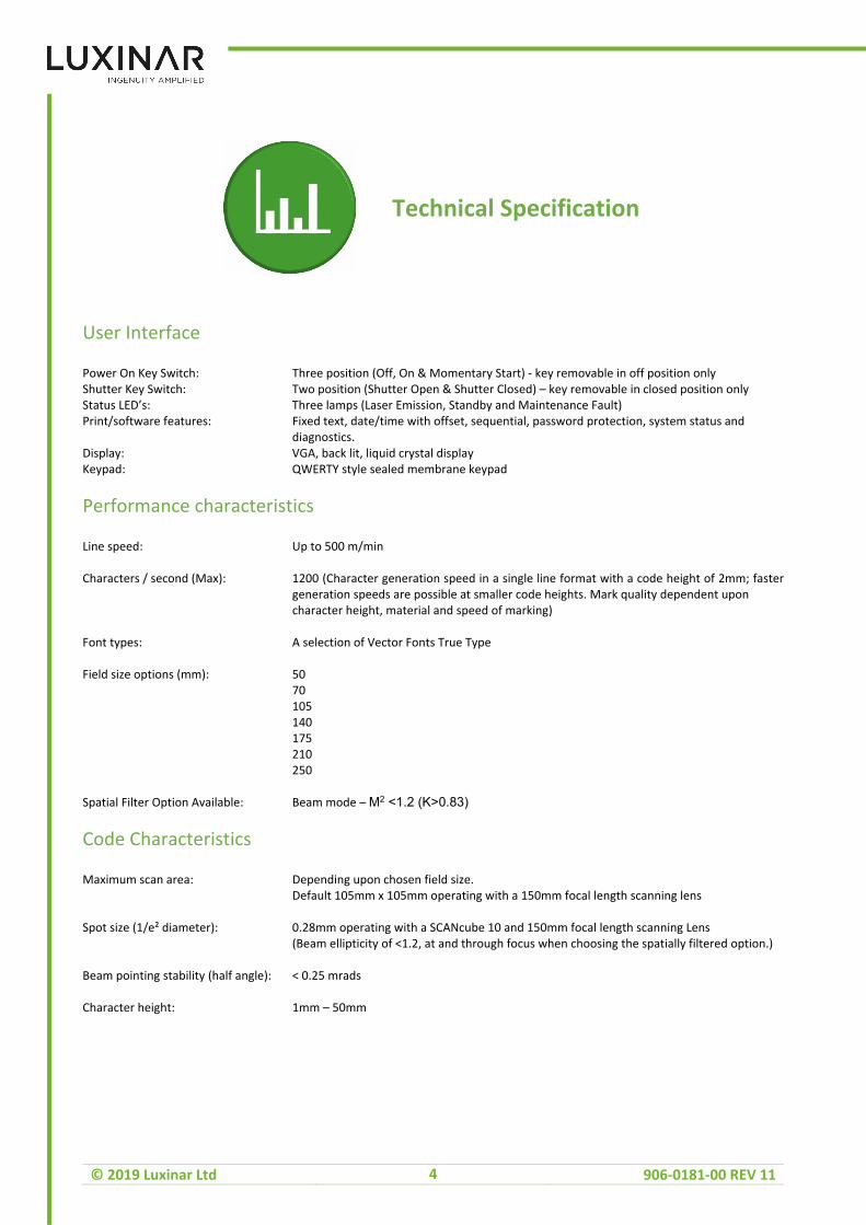
User Interface
Power On Key Switch: Three position (Off, On & Momentary Start) - key removable in off position only Shutter Key Switch: Two position (Shutter Open & Shutter Closed) – key removable in closed position only Status LED’s: Three lamps (Laser Emission, Standby and Maintenance Fault) Print/software features: Fixed text, date/time with offset, sequential, password protection, system status and diagnostics. Display: VGA, back lit, liquid crystal display Keypad: QWERTY style sealed membrane keypad
Performance characteristics
Line speed: Up to 500 m/min Characters / second (Max): 1200 (Character generation speed in a single line format with a code height of 2mm; faster generation speeds are possible at smaller code heights. Mark quality dependent upon character height, material and speed of marking) Font types: A selection of Vector Fonts True Type Field size options (mm): 50 70 105 140 175 210 250 Spatial Filter Option Available: Beam mode – M2 <1.2 (K>0.83)
Code Characteristics
Maximum scan area: Depending upon chosen field size. Default 105mm x 105mm operating with a 150mm focal length scanning lens Spot size (1/e² diameter): 0.28mm operating with a SCANcube 10 and 150mm focal length scanning Lens (Beam ellipticity of <1.2, at and through focus when choosing the spatially filtered option.) Beam pointing stability (half angle): < 0.25 mrads Character height: 1mm – 50mm

© 2019 Luxinar Ltd 906-0181-00 REV 11
5
External Interface
Product detector input: Two independent inputs for NPN or PNP product detector, 24 or 12Vdc Product detector output: Two independent outputs for external monitoring of the product detector input signals Shaft encoder/Tacho: Input for control of 'on-the-fly' marking for variable speed production lines Tacho Fault: Input for monitoring the status of the Tacho Dual Estop Interlocks: Two independent inputs for provision of a remote emergency stop and remote (guard) interlocks System on: Output for external monitoring of power on/power off for the system Ready to print: Output for external monitoring the status of the system ie. standby or ready to print Product reject: Output for rejecting unmarked product Shutter status: Two independent outputs for external safety monitoring of the safety shutter status ie. open or closed System enable: Input for the provision of externally enabling or disabling the system Extractor enable: Output to enable the extractor when the system is ready to print Extractor fault: Input for monitoring the status of the extractor Good mark: Output for external monitoring of the status of each individual mark Maintenance required: Output for external indication that maintenance is required System Fault: Output for monitoring when the system has a fault and is therefore not ready to print System RS232/RS485: Communications port for file download/external fields Maintenance
External Materials
Main cabinet: Stainless steel 303 chrome plated mild steel fixings User interface panel: Anodised aluminium Articulated arm: Anodised aluminium Scanning head: Anodised aluminium
Environmental specification
Air-cooled systems Ambient operating temp.: +5 to +35ºC (+41 ºF to +95ºF) Water-cooled systems Ambient operating temp.: +5 to +40ºC (+41ºF to +104ºF) Storage temperature: -10 to +70ºC (+14 to +158ºF) Humidity: 10 to 90% relative humidity (non condensing) Seal rating: IP56 (NEMA 4)
Laser head and beam delivery characteristics
Powers and energies are quoted at the point where the laser beam exits the Cabinet. If choosing a spatially filtered option with MSVS, all specified values will reduce by 8 to 12% Laser tube: Sealed Cavity, RF excited, Diffusion Cooled, Slab Carbon Dioxide Laser Laser output: From scanning head Pulsed CO₂ laser with scanned laser radiation output Wavelength: 10.17 – 10.7μm Excitation frequency: 81 MHz Typical Tube lifetime: > 5 years

© 2019 Luxinar Ltd 906-0181-00 REV 11
6
Average Rated Output power (typical): 125 watts Peak power (maximum): 315 watts Pulse Frequency range: 0 Hz to 100 kHz Pulse Width range: 2 to 400 μs Energy range: 5 to 100 mJ Duty cycle (maximum): 60% Minimum Shipment Power: 150 watts Optical rise / fall times: 60 μs (Rise and fall times are quoted between the 10 and 90% levels) Beam divergence: For safety considerations, the output beam exiting the articulated arm aperture (with no scanning head attached) should be considered near parallel and does not diverge. Articulated beam delivery: Fully articulated beam delivery with pre- aligned optics – standard reach 1.2m (3.94ft) Head to product distance 150mm (Operating with a 150mm focal length scanning lens). Polarization: Linear rotated
Coolant details
Cooling type: Self-contained, forced air-to-water heat exchanger with internal water pump or external chiller. Coolant specification: Hydratech CoolFlow / Distilled Water mixture in a 3:1 concentration See 904-0084-00 for further details Data Sheet Available From http://www.hydratech.co.uk/pdf/cffg.pdf Please refer to document 906-0202-99 for the minimum coolant temperature tables
Mechanical characteristics
Overall external dimensions: Cabinet Height: 830mm Width: 390mm Depth: 588mm Overall weight: 120kg Scanning head 7 10 14 Height: 78.5mm 114mm 133mm Width: 69mm 96.5mm 99.5mm Depth: 77.9mm 94mm 105.5mm Weight (kg): 0.65 1.9 2.3 Orientation horizontal Aperture

© 2019 Luxinar Ltd 906-0181-00 REV 11
7
Electrical characteristics
Electrical supply: V AC ± 10% Single phase or line to line (bi-phase) 200 210 220 230 240 Power consumption: 2.4kVA peak for continuous laser output typically <500VA for normal print duty Maximum current: 12 ampere maximum average @230Vac 16 ampere maximum peak @ 230 Vac Mains input connection: Plug and socket type to IEC 309 (mains cable to be supplied at installation – this equipment
must be connected to an electrical earth) Altitude During Operation: <2000m
Fuses
All fuses are located inside the system on the fuse board apart from fuse F3001 which is located on the DC power supply. Fuse changes should only be attempted by trained service personnel. Fuse Description Type F2201 Mains input 16A gL-gG 700V F2202a Mains input 16A gL-gG 700V F2203 Mains to DC power supply 16A URZ 500V F2204a Mains to DC power supply 16A URZ 500V F2205 Mains to auxiliary transformer T3.15AH250V F2206a Mains to auxiliary transformer T3.15AH250V F2207 Mains to fan T1AH250V F2208a Mains to fan T1AH250V F2209 Mains to pump T1AH250V F2210a Mains to pump T1AH250V F2211 Auxiliary 24V to interlocks T1AH250V F2212 Auxiliary 24V to scanner drive T3.15AH250 F2213 Auxiliary 24V to processor brd. T3.15AH250 F2214 Auxiliary 24V to processor brd. T3.15AH250 F3001 48Vdc to trigger gap T500H250V Notes: Fuses described above are for line to line (bi-phase) systems. When the system is connected to a single phase supply (with a neutral connection) the fuses marked with (a) are replaced with neutral links or removed.
Enquiries
Every effort has been made to ensure that the information in this manual is correct, however components may be subject to design changes and upgrading, from time to time. Please direct any questions or comments on this manual to Customer Services Department, stating the part number and revision given at the bottom of this page. Immediate response, to any service enquiries, can be achieved by contacting the relevant Distributor Service Office. Always identify the instrument, by both the model number and the serial number, in all correspondence. This information is contained on the serial number panel, which is located on the rear panel of the system, just above the mains power isolator switch.
Warranty Information
All special warranty terms, eg. Laser tubes, etc., are contained in the System warranty terms that are current, when the system is purchased. Copies of the System Warranty Terms can be obtained from the Manufacturer.

© 2019 Luxinar Ltd 906-0181-00 REV 11
8
Warranty Shipments, Returns and Adjustments
Warranty claims must be made promptly and must be received by Luxinar Ltd., during the applicable warranty period. If it becomes necessary to return a product for repair and/or adjustment, authorisation from Luxinar Ltd. for the return and instructions as to how and where these products should be shipped must be obtained from the Service Department. Service Department Luxinar Ltd. Meadow Road Bridgehead Business Park Kingston upon Hull HU13 0DG U.K. Telephone: +44 (0) 1482 650088 Fax: +44 (0) 1482 650756 Note: Drop the 0 for international calls (UK country code is 44)
Service and Repair
Servicing or calibration of the system can only be carried out by trained Distributor Service Engineers or customers who have undertaken and passed an approved service training course. Details of training courses and servicing can be obtained from the local Distributor Service Office

© 2019 Luxinar Ltd 906-0181-00 REV 11
9
Operation
The system can be turned on, operated and programmed using the controls, the QWERTY keypad and the display on the user interface panel. The software is the subject of a separate software manual, the version of which will depend on the version and type of software that is resident in the system. The basic operations, adjustments, start up and switching off of the system are discussed in this section of the manual.
Laser Output Aperture
Figure 4 Laser Output Aperture
Warning – Use of controls or adjustments or performance of procedures other than those specified herein may result in hazardous laser radiation exposure. This is a Class 4 (Class IV) Laser and the beam is invisible to the eye. Please review all safety instructions and precautions given in the safety section before attempting to operate or service the system.
IMPORTANT - Do not attempt to connect, disconnect or re-connect the galvo cable before first ensuring that the power to the system is switched off. Caution – never apply excessive torque or leverage to the articulated arm. Although of a very rugged construction, the articulated arm is precision aligned and any damage to the arm may result in misalignment of the laser beam into the scanning head.
CAUTION! CLASS 4(IV) LASER RADIATION EMITTED FROM THE APERTURE SHOWN BELOW.
© 2019 Luxinar Ltd 906-0181-00 REV 11
10
Emission Warning Lamp
A green Emission Warning Lamp (shown in Appendix 1 – A1.11) is located on the user interface panel.
If the emission lamp fails during operation of the system, then an emission lamp failure indication is provided on the liquid crystal display on the control panel.
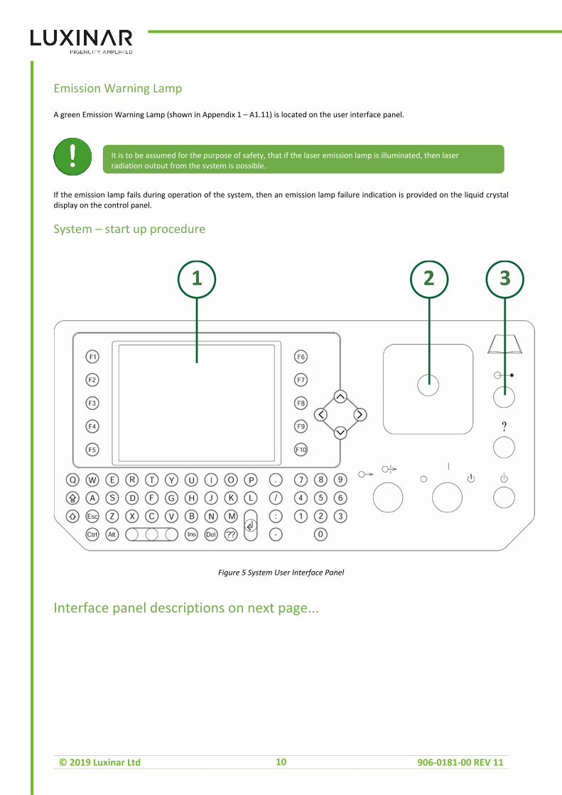
System – start up procedure
Figure 5 System User Interface Panel
Interface panel descriptions on next page...
It is to be assumed for the purpose of safety, that if the laser emission lamp is illuminated, then laser radiation output from the system is possible.

© 2019 Luxinar Ltd 906-0181-00 REV 11
11
Interface Panel
1
VGA, back lit, liquid crystal display
2
Emergency Stop Button – red mushroom head type
3
Emission Lamp
Graphic symbol to indicate that the power key switch is in the off position
Graphic symbol to indicate that the power key switch is in the on position
Graphic symbol to indicate the momentary start position for the power key switch
Graphic symbol to indicate shutter closed position for the shutter key switch
Graphic symbol to indicate the shutter open position for the shutter key switch
Graphic symbol to indicate Laser Radiation Emission Lamp
Graphic symbol to indicate a maintenance fault that prevents the system from printing
Graphic symbol (to 417-IEC-5009a) to indicate that the system is in a standby mode and will not print until the operator has performed an operation as indicated on the control panel display
Refer to Operating Manual

© 2019 Luxinar Ltd 906-0181-00 REV 11
12
Preliminary checks
• Ensure the power is connected via the mains socket on the rear panel of the system. • Check that the system’s remote interlock connection and the remote emergency stop circuit are made through the external interface. See the separate Installation manual (part no. 906-0149-00) if in doubt regarding the connections. • Check that the system can receive signals to mark from a triggering device such as a product detector connected to the external interface. Refer to the separate Installation manual (part no: 906-0149-00) if in doubt regarding the connections. • The ’System Status’ screen also displays warnings with a message.
System turn on
• Turn the Mains Isolator Switch on the rear panel of the system to the (on) position. At this stage, the system will initialise and the lamps will come on momentarily for a lamp test. Note that after initialisation, the last code printed is shown in the top part of the display on the ‘Print’ screen and the Standby and Laser Emission lamps will be illuminated. • Referring to Figure 5, insert the Shutter and Power Keys into the Shutter Key Switch and Power Key Switch respectively. Ensure both keys are in the 0 (off) and shutter closed positions. • Ensure that the Emergency Stop Button is released – slight rotation clockwise to release. • Turn the Power Key to the I (on) position. • Turn the Power Key to the momentary start position and release the key back to the I (on) position. This action turns on the DC power supply and enables the laser. The DC power supply will take approximately 15 seconds to energise. During this time, the system will not print and a warning message will be displayed “waiting for 48V supply”. • Turn the Shutter Key to the shutter open position. • The last code used will displayed in the top half of the display, press F10 to print the code. This action enables the system to print. • Products that interrupt the product detector should now be printed with the message shown in the top part of the user display.
Recommendations
• Printing While printing, changing to different screens (status / settings / edit etc) incurs additional software processing time which may in some instances momentarily interrupt the repetition of the print. It is therefore important to avoid changing screens where possible while printing.
Focus Adjustment
• Run a test product down the production line past the scanning head and examine the mark produced. Compare the new mark with the previous mark and ensure that the spot size and mark quality is comparable. • If the spot size is not similar then slight adjustment of the scanning head position may be necessary. First switch off the system and isolate from the mains supply and then loosen the scanning head clamping mechanism. • Now move the scanning head slightly forward by about 1 or 2mm and repeat instruction above. Note that only small movements should be necessary to achieve a perfect mark. • If the spot size increases then repeat the above procedure, but move the scanning head in the opposite direction by 1 or 2mm. It may take several small movements to achieve the best quality mark and spot size.

© 2019 Luxinar Ltd 906-0181-00 REV 11
13
Optimising mark codes for 'on-the-fly' marking
When marking on-the-fly, the capability of the system to mark at a particular line speed depends on a number of factors. The laser marking parameters are optimised for the fastest marking, while maintaining an acceptable marking quality. The total time to mark a code is affected by the following parameters:- Mark speed / Jump speed / Mark delay / Jump delay / Polygon delay The following parameters do not affect the overall mark time, only the quality of the mark:- Off delay / On delay / Frequency / Duty The following factors should also be considered when determining the mark time: - • The number of characters • The size of the characters • The font – simple line fonts are marked in less time than bold two or three line fonts. • The jump distances between fields. Automatic or manual optimisation can be applied to a mark code. This allows the marking order, direction and position to be changed to achieve an optimised code for on-the-fly or static marking. Refer to the Software Manual for further details (906-0039-xx).
Switch Off Procedure
1 Press the Shut Down Button as shown below,

© 2019 Luxinar Ltd 906-0181-00 REV 11
14
Then wait for the confirmation screen
• Turn the shutter key switch to the closed position. • Turn the power key switch to the 0 (off) position. • Turn the mains isolator switch on the rear of the system to the off position. Note that the power and shutter keys can only be removed in the off position. When the system is switched off, the keys should always be removed and kept in a secure location to prevent unauthorised use of the laser system. As an extra precaution, the isolator switch is designed so that it can be padlocked in the off position.
Manual Restart
It is a statutory requirement of 21 CFR 1040.10 that the laser output should not be restored automatically if the mains power fails or an interlock is broken and then reset. This is also a requirement of EN 60825-1:2014, where a remote interlock connection is being used as a safety interlock on an access panel of a protective enclosure that when removed, will change the class of the installed system to a Class 4 (Class IV) laser product. • Mains Power Failure In the event of a mains power failure, the laser and its power supply will be disabled and will not be restored when the mains power is re-established. In order to restart the laser system, turn the isolator switch to the off position and then repeat the System Turn On procedure given on page 19. • Remote Interlock Broken In the event that the remote interlock is broken, e.g. opening of the beam guarding door, the laser will be disabled. When the remote interlock is restored the series of events to re-enable the laser to print depends on the Interlock Mode chosen in the hardware/software. The default factory setting is Interlock Mode 1 and in this case the laser will not be re-enabled when the remote interlock connection is restored e.g. guarding door is closed. Mode 1 meets the safety requirements of CDRH and EN 60825-1:2014. In order to restart the laser after a remote interlock re-make: (Jumper configuration required on fuse board)

© 2019 Luxinar Ltd 906-0181-00 REV 11
15
• Interlock Mode 0 1 Return the Shutter Key to the closed position. 2 Turn the Power Key to the momentary start position and release back to the I (on) position. This action turns on the DC power supply and enables the laser. The DC power supply will take approximately 15 seconds to energise. During this time, the system will not print and a warning message will be displayed - “Waiting for DC”. 3 Turn the Shutter Key to the open position. This action enables the system to print. • Interlock Mode 1 1 Press the Print button 2 Press 'Yes' to confirm laser activation • Interlock Mode 2 This is an automatic mode which means that the system will restart and the laser is enabled as soon as the interlock is remade.
Remote Keyboard (factory fitted option)
There are few differences between the standard system operation and the remote keyboard version. Assuming the keyboard is fully connected, when the main system AC power is turned on, the LCD screen should illuminate and a BIOS start-up screen will appear. Without pressing any keys the application software should be launched and appropriate menus displayed. This process takes approximately 3 minutes. In the remote keyboard version of the vector marking system, there are these additional features: - • The screen/keyboard/key-switches and monitor lamps are now located in a separate housing to be plugged into the main unit via a 5-metre umbilical. These items function as in the standard vector system. • The top plate of the laser assembly has a simplified layout containing 3 indicator lamps and an Emergency Stop switch. The lamps show the same pattern on both the main unit and the remote keyboard. • Either of the Emergency Stop switches may be used to stop the system printing. They do not stop the computer system. If the umbilical or keyboard is not present or not connected properly, the system cannot operate as the interlocks go through these items. • All 6 coloured indicators use LEDs and spares are provided. • Only the Emission Indicator devices are monitored for open circuit/short circuit faults. If either LED is removed or shorted, the system is capable of detecting and reporting this state while printing. • The LEDs on the main laser unit and the keyboard unit always agree.
It is the responsibility of the user to ensure that the Interlock Mode chosen fully conforms to local safety regulations governing use of the laser. For more information on safety please refer to the safety section at the start of this manual

© 2019 Luxinar Ltd 906-0181-00 REV 11
16
Maintenance
General Information
The system range of systems, have been designed to be low maintenance marking lasers with low consumable costs. The only routine maintenance procedures which can be carried out are listed below. Check Frequency Comments Scan head Output Optic 1-3 Months Depends on environment, for cleaning procedure see page 24 Indicator Lamps Every 3 Months Bulb Part Numbers: 607-0023-00 (RED) 607-0024-00 (YELLOW) 607-0025-00 (GREEN) See page 26 Interlock Operation Every 6 Months See page 21 Liquid Coolant Every 6 Months Check levels are OK and there are no leaks. 18 Months Replace Coolant. This should only be carried out by a trained Engineer. The system's sealed construction and limited moving parts ensures trouble free and reliable operation with any internal faults being reported by the system’s software controlled monitoring system. Some external items will require periodic inspection and cleaning. These include the final optical element on the Scanning Head, the Compressed Air Supply, the Product Detectors and the Extraction System Filters. The frequency of inspection and cleaning will depend on how the system is integrated into the customer’s machine and more importantly, how well the final optic is protected from dust and contamination. Warning – Use of controls, adjustments or performance of procedures other than those specified herein may result in hazardous laser radiation exposure. This is a Class 4 (Class IV) Laser and the beam is invisible to the eye. Please review all safety instructions and precautions before attempting to operate or service the system. Always ensure that the laser system is switched off and isolated from the mains supply before attempting any cleaning or maintenance procedures.
Warning – Use of controls, adjustments or performance of procedures other than those specified herein may result in hazardous laser radiation exposure. This is a Class 4 (Class IV) Laser and the beam is invisible to the eye. Please review all safety instructions and precautions given at the start of this manual before attempting to operate or service the system. Always ensure that the laser system is switched off and isolated from the mains supply before attempting any cleaning or maintenance procedures

© 2019 Luxinar Ltd 906-0181-00 REV 11
17
Cleaning Optical Surfaces
The information contained in this section is intended to be used as a general guideline for cleaning optical grade materials. It is strongly recommended that a thorough understanding of this section be attained before any optic cleaning or handling procedures are attempted. Peak performance and efficiency of optical systems is only possible when the surfaces of the optical components are absolutely free of contamination. For example, a film of oily substance or specks of dust can substantially reduce the performance of the system. In most cases this will be seen as a gradual deterioration in the intensity of the beam on the target material ie. fading mark quality. Optical surfaces can be irreparably damaged by seemingly harmless debris or lint. Always switch off the laser system and isolate from the mains supply before proceeding with the cleaning of any optical surfaces on the system. This section is designed to introduce correct and safe methods for the cleaning of optical components. • Output Lens The only externally exposed optical surface on the system is the output lens on the Scanning Head. Depending on the orientation of the Scanning Head, the output lens may be more susceptable to dirt/debris (for instance if the scanner is pointing upwards). The recommended maintenance schedule should be adjusted accordingly. The most common sources of surface contaminants are fingerprints and airborne contaminants (dust, lint, smoke, etc.). If allowed to remain on optical surfaces, such contaminants will cause absorption and light scattering and in extreme cases this may permanently damage the optic and its coatings. If removed improperly, this debris can cause permanent damage. Remove any beam delivery or beam shroud and inspect the output optic. Clean if necessary, observing the methods described in this section. Leave the optic in its holder during the cleaning process. • Optics Cleaning Materials Lens tissue (first quality) Tissues (non-perfumed for rough work, wiping hands, etc). Disposable lint-free gloves. Solvents (highest purity, preferably anhydrous): Methanol, Ethanol, Isopropyl Alcohol (99.5% purity) Photographic blower brush • Cleaning Optical Surfaces Hands should be thoroughly washed to remove all oils, perspiration and grit. The hands should then be rinsed free of soap. Lint free gloves can be used for added protection of the optic. If there is visible dust, lint or other solid matter on the optics surface, gently blow it off with a photographic blower brush. Coated optics require careful handling, even the type labelled 'hard-coated'. If the surfaces are not badly contaminated, cleaning can be done fairly easily, a fresh sheet of lens tissues folded to form a pad

© 2019 Luxinar Ltd 906-0181-00 REV 11
18
several layers thick. Its size will be a compromise between fully covering the diameter or width of the surface and being too large to clean evenly. Enough optical grade solution to just dampen the pad should be applied with a medicine type dropper. The pad should then be drawn across the surface in one smooth stroke, using very light pressure. The soiled pad must then be discarded. Repeat as necessary, using a clean pad for each stroke. Using new pads each time will minimise the possibility of scratching the optical coating. When the optic is clean, replace the optic and lens shroud and reconnect the compressed air. Where severe contamination has permanently damaged the optic, replace with a new component of the correct specification and in the correct orientation.
Compressed Air Supply
A compressed air supply is required where there is a possibility of contamination of the final lens which is normally due to the particulate matter produced as a by-product of the marking process. Contamination of the final lens will result in poor quality marking or in the worst case, no mark on the product to be coded. To prevent this contamination, a clean compressed air supply is recommended to provide slight positive pressure on the final lens shroud. The recommended specification is given in the Installation Manual. The recommended two stage air filtering will need regular inspection and maintenance where necessary and the period between inspections will vary depending on the quality of the initial air supply. As a basic guide, these filters should be inspected on a weekly basis after initial installation. Where necessary, replace or clean the filters, referring to the manufacturer’s instructions. Blocked filters may indicate that the final lens is also contaminated – refer to page 23. Where filters are found to be clean, the period between inspections can be increased, it is recommended that the maximum time between inspections should be no more than one month.
Product Detectors
Always ensure that the laser system is switched off and isolated from the mains supply before attempting any cleaning of the product detectors. In general, product detectors can be occasionally wiped with a clean damp cloth to remove contamination from the active surfaces. Take care not to move or disturb the detectors during cleaning as this may affect code position on the product to be marked. Do not use abrasive materials as these may damage the detectors and render them inoperative. See the manufacturer’s instructions for more information on cleaning. The period between cleaning will depend on the environment of the production line. An initial daily inspection can be increased to a maximum of a weekly inspection where detectors are cleaned infrequently.
Extraction
An approved fume extraction unit should be fitted to all installations where particulate matter or fumes are produced as a by-product of the marking process. The manufacturer of the extraction unit should recommend the correct filter combination to effectively control the fume produced in the marking process, which will depend on the materials of the substrate to be marked. Where the marked product materials are altered or changed after initial installation, then consult the local Distributor and the manufacturer of the extraction equipment for any required change to the extraction filter specification.

© 2019 Luxinar Ltd 906-0181-00 REV 11
19
The filters used in the extraction system must be regularly inspected, changed and disposed of in accordance with the manufacturer’s instructions. In broad terms, this will depend on the construction of the extraction system, the filter capacity and the amount of debris produced by the marking process. Where possible use an extraction system with a built in filter monitoring device for automatic filter blockage detection.
Replacing faulty Indicator Lamps
It may be necessary to replace the indicator bulbs on the user interface panel, if this is the case please follow the instructions below. • To check the operation of the indicator bulbs, whilst the system is in standby mode, activate the Emergency Stop button. All three indicator bulbs should now be lit. To replace any faulty bulbs, following instructions below. • Remove the coloured lens from the lamp holder to gain access to the faulty bulb. The bulb can then be removed using the bulb puller tool part number 553-0004-00, (shown here below Figure 6) which is provided in the spares kit supplied with the system.
Figure 6 Replacing faulty indicator lamps
Figure 7 Bulb Puller, part number 553-0004-00
Always switch off the laser system and the extractor and isolate from the mains power supply before proceeding with the inspection of extraction filters.

© 2019 Luxinar Ltd 906-0181-00 REV 11
20
PC System Battery Replacement
The internal PC in this system uses a CR2032 battery. If this battery needs to be replaced it should only be replaced with a battery of the same type, by trained personnel.
General Cleaning
Always ensure that the system is switched off and isolated from the mains supply before attempting any cleaning procedures. The system is supplied with two key switch covers (see below). They must be fitted over the key switches before attempting any cleaning or wash-down procedures The external surfaces of the system can be cleaned with a mild detergent. It is advisable to use a damp cloth to facilitate the cleaning of the external cabinets, etc. Take care not to allow water into the system cabinet or the final optic beam shroud.
Figure 8 Keyswitch covers
CAUTION! RISK OF EXPLOSION IF BATTERY IS REPLACED BY AN INCORRECT TYPE. DISPOSE OF USED BATTERIES ACCORDING TO THE INSTRUCTIONS.

© 2019 Luxinar Ltd 906-0181-00 REV 11
21
Appendix 1
Safety Labels
A1.0 System Safety Labels ( 905-0239-00 ) As required by EN 60825-1:2014 and 21 CFR 1040.10, appropriate warning labels have been positioned in specific locations on the system to indicate conditions under which the user could be exposed to laser radiation. The following gives details of those labels, their part numbers and their specific positions on the system. Note that the mains input voltage and current ratings are given on the serial number label (A1.10)
The Laser Hazard symbol is intended to warn the operator of the possibility of hazardous laser radiation. A1.1 Laser Hazard Symbol
A1.2 Class 4 Laser Warning Label

© 2019 Luxinar Ltd 906-0181-00 REV 11
22
A1.3 Laser Technical Data Label
A1.4 Laser Aperture Label
A1.5 Non Interlocked Panel Label There are two non-interlocked panel labels used inside the system for labelling two covers that prevent access to the laser beam when the cabinet covers are removed.
A1.6 Cover Warning Label
A1.7 Equipment Earth Warning Label

© 2019 Luxinar Ltd 906-0181-00 REV 11
23
The voltage hazard label is used inside the system to warn of voltage hazards when the cabinet covers are removed. A1.8 Voltage Hazard Label
A1.9 Refer to Manual for Instructions Label
1 Model Number 2 Part Number 3 Serial Number 4 Input 5 Tube Type 6 Tube Serial Number 7 System Revision 8 Weight 9 Tube Part Number 10 Tube Revision 11 IP Number
1.10 Product Identification and Certification Label

© 2019 Luxinar Ltd 906-0181-00 REV 11
24
A1.11 Emission Warning Lamp (position on system)

© 2019 Luxinar Ltd 906-0181-00 REV 11
25
A1.12 Position of safety labels 1

© 2019 Luxinar Ltd 906-0181-00 REV 11
26
A1.13 Position of safety labels 2

© 2019 Luxinar Ltd 906-0181-00 REV 11
27
APPENDIX 2
Additional Drawings

© 2019 Luxinar Ltd 906-0181-00 REV 11
28

© 2019 Luxinar Ltd 906-0181-00 REV 11
29

© 2019 Luxinar Ltd 906-0181-00 REV 11
30

© 2019 Luxinar Ltd 906-0181-00 REV 11
31

© 2019 Luxinar Ltd 906-0181-00 REV 11
32

© 2019 Luxinar Ltd 906-0181-00 REV 11
33

© 2019 Luxinar Ltd 906-0181-00 REV 11
34

© 2019 Luxinar Ltd 906-0181-00 REV 11
35

© 2019 Luxinar Ltd 906-0181-00 REV 11
36

© 2019 Luxinar Ltd 906-0181-00 REV 11
37
APPENDIX 3
Additional Information
A3.0 Revision History REV 11 updated 19/02/2019 Luxinar format

Luxinar Ltd Meadow Road Bridgehead Business Park Kingston upon Hull U.K. HU13 0DG Tel: +44 (0) 1482 650088 www.luxinar.com FEB 2019
CLASS 4 INVISIBLE
LASER RADIATION