901 NEW YORK TäxÇâx
24
Technical Assignment 1 Memari Structural Concepts/Structural Existing Conditions Report 901 New York Avenue Page 1 of 24 901 NEW YORK TäxÇâx Structural Technical Report 1 Structural Concepts/Structural Existing Conditions Report 901 New York Avenue Washington, D.C. Advisor: Ali Memari Written by: Timothy H Park
Transcript of 901 NEW YORK TäxÇâx

Technical Assignment 1 Memari Structural Concepts/Structural Existing Conditions Report 901 New York Avenue
Page 1 of 24
901 NEW YORK TäxÇâx
Structural Technical Report 1 Structural Concepts/Structural Existing Conditions Report 901 New York Avenue Washington, D.C. Advisor: Ali Memari Written by: Timothy H Park

Technical Assignment 1 Memari Structural Concepts/Structural Existing Conditions Report 901 New York Avenue
Page 2 of 24
Executive Summary 901 New York Avenue Multi-Use Facility Structural Concepts/Structural Existing Conditions Report is the first of 3 technical assignments for thesis. It focuses on the general design of the building, from foundations to the floor system. This report is on some of the structural concepts used in the 11-story 901 New York Avenue building. Preliminary research and calculations shall be done to determine type of lateral system, floor system, foundation integrity, codes used and applied, and general loadings.
901 New York Avenue is an 11-story cast-in-place multi-use facility. The foundation comprised of footing sizes of varying sizes (see report). The floor system was found to be a two-way post-tensioned system (see picture left), with bay sizes as large as 20’-0” by 40’-0” (which is the typical bay size). Primary columns are placed with respect to the bays. Lateral forces are resisted through moment framing, which means that this building has no shear walls.
This multi-use facility was designed using the 1996 BOCA Building Code, which was current at the time of construction. This report utilizes the more recent ASCE/SE 7-05, Minimum Design Loads for Buildings and other Structures. ASCE/SEI 7-05 was used to find gravity, wind, snow, rain, roof, and seismic loads. Spot checks were done on various locations to ensure the satisfaction of design: the two-way slab, columns, and foundation footings. Both columns and footings were calculated with pure axial loads. The two-way slab was calculated through the Equivalent Framing Method. Most of the results proved that the design of the building was to satisfaction. Failing results are addressed in the report as well. Foundations were also concluded to be satisfactory. After analysis and research of 901 New York Avenue, the building satisfies all checks and code requirements. Spot checks showed under design on the slab and over design on the columns. This is due to the fact that the slab analysis does not take into effect the post-tensioning system, and the columns are also meant to take on some flexural loading due to the lateral forces. The spot checked footing also turned out with different reinforcement requirements and size. Most of these different values may contribute to the fact that spot checks observe individual loads on respective concepts (columns and foundations are assumed to take just axial loads, non-stressed slabs are assumed to be the sole shear resisting force). These spot checks have expressed the complexity of this building, with its post-tensioned system with no shear walls and isolated footings. Spot check, load, and lateral calculations can be found in the Appendix as listed in the Appendix Table of Contents (page ).
QuickTime™ and aTIFF (LZW) decompressor
are needed to see this picture.

Technical Assignment 1 Memari Structural Concepts/Structural Existing Conditions Report 901 New York Avenue
Page 3 of 24
Introduction This report is a summary of general structural concepts used in the building construction of the 901 New York Avenue 11-story office building. This 580,000 square-foot building (which is actually a mixed-use facility) was built by Boston Properties and completed in 2004. The building primarily consists of 3 components: the underground parking garage, the ground-level commercial space, and the upper-level office spaces. Located in the heart of the city (directly across from the Convention Center), the building is a central attraction to all those passing by. The shape of the building is a noticeable right-angled triangle.
Figure 1 – Location of 901 New York Avenue
This report consists of 5 main portions: the overall structural system, building codes used and applied, framing systems analysis, design loads, and spot checks.
Technical Assignment 1 Memari Structural Concepts/Structural Existing Conditions Report 901 New York Avenue
Page 4 of 24
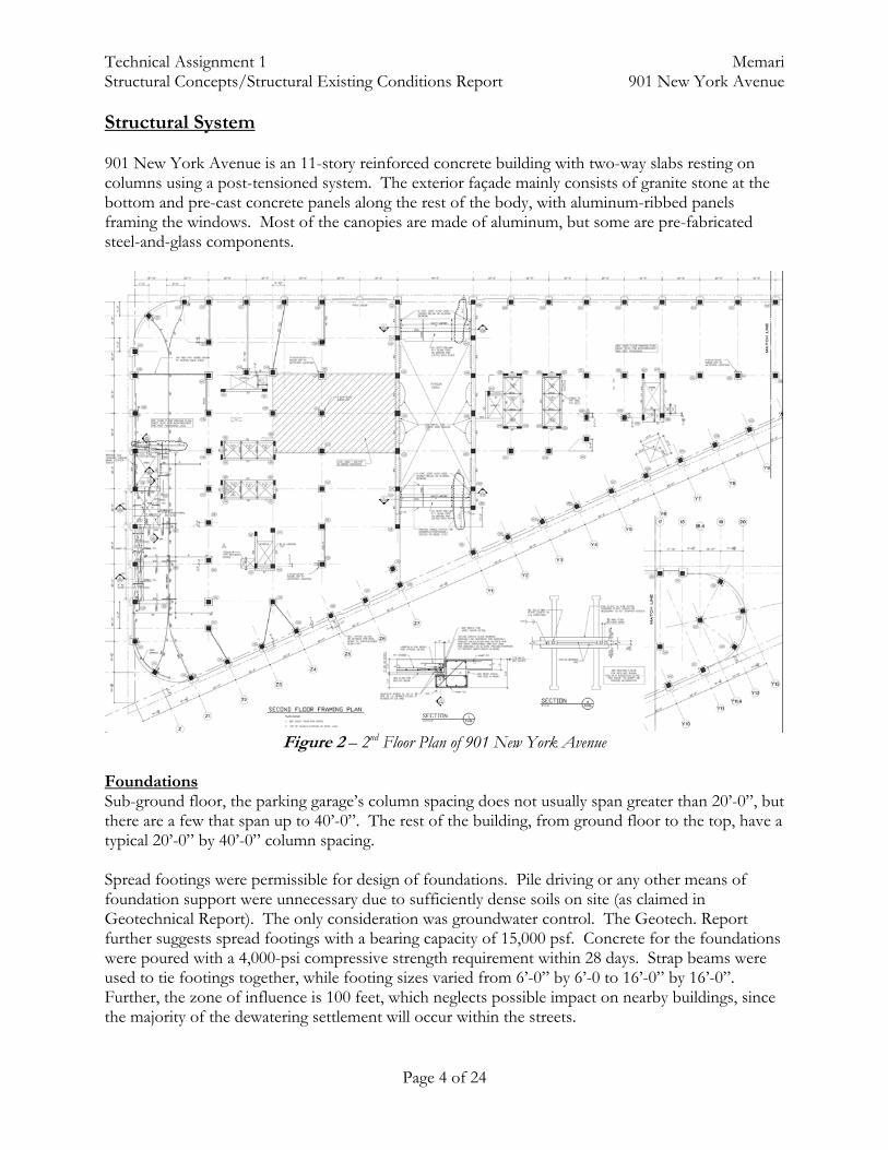
Structural System 901 New York Avenue is an 11-story reinforced concrete building with two-way slabs resting on columns using a post-tensioned system. The exterior façade mainly consists of granite stone at the bottom and pre-cast concrete panels along the rest of the body, with aluminum-ribbed panels framing the windows. Most of the canopies are made of aluminum, but some are pre-fabricated steel-and-glass components.
Figure 2 – 2nd Floor Plan of 901 New York Avenue
Foundations Sub-ground floor, the parking garage’s column spacing does not usually span greater than 20’-0”, but there are a few that span up to 40’-0”. The rest of the building, from ground floor to the top, have a typical 20’-0” by 40’-0” column spacing. Spread footings were permissible for design of foundations. Pile driving or any other means of foundation support were unnecessary due to sufficiently dense soils on site (as claimed in Geotechnical Report). The only consideration was groundwater control. The Geotech. Report further suggests spread footings with a bearing capacity of 15,000 psf. Concrete for the foundations were poured with a 4,000-psi compressive strength requirement within 28 days. Strap beams were used to tie footings together, while footing sizes varied from 6’-0” by 6’-0 to 16’-0” by 16’-0”. Further, the zone of influence is 100 feet, which neglects possible impact on nearby buildings, since the majority of the dewatering settlement will occur within the streets.
Technical Assignment 1 Memari Structural Concepts/Structural Existing Conditions Report 901 New York Avenue
Page 5 of 24
Foundation walls are 36” thick throughout the entire perimeter of the building (parking garage level). Slab-on-grade had a thickness of 5” using 6x6-W2.0xW2.0 WWF as reinforcement. Below the S.O.B. was the vapor barrier and 6” of crushed stone. Slabs The parking garage had the following typical slab system of a 28-day compressive strength test of 5,000 psi at 8”. Exceptions are at framed floor slab below columns, which was poured with 8,000 psi concrete. Certain portions of the slab also had a 4” concrete fill on top the typical slab (as noted in darker hatching), while some areas used lighter-weight concrete at 4” (as noted in lighter hatching). The slabs above the parking garage are typically 11” slabs with the same 5,000 psi concrete. Truck bays have an increased 12” slab with a 4” topping above it. Columns Spacing of the building consisted of 20’-0” by 20’-0” in the parking garage and a typical spacing of 20’-0” by 40’-0” from the ground level up. From the fourth level of the parking garage (level P4) up to the second floor, the compressive strength of the columns are designed to be 8,000 psi. The third and fourth floors have strength of 6,000 psi. The fifth and sixth floors have strength of 5,000 psi. The rest of the stories have a compressive strength of 4,000 psi. Typical sizes of the columns are a square 26” by 26”, varying mostly only in reinforcement. The bays that actually span the full 20’-0” by 40’-0” spans have a typical 32” by 32” column design throughout the floors. The garage level columns are a bit larger, ranging from 24” by 30” to 24” by 36”. They vary in height with an average of about 11’-0” (floor-to-floor height is roughly 11’-8” from the second story up). More definite numbers are shown in the spot check calculations.
Technical Assignment 1 Memari Structural Concepts/Structural Existing Conditions Report 901 New York Avenue
Page 6 of 24
Building Codes Used and Applied 901 New York Avenue is located in the heart of the city. By zoning classifications, it is square #372, district C-4 (PUD). The building takes up the full lot area, which is 53,252 square feet, and has a height limitation of 130’-0”. Building Code Because the office facility is in the District of Columbia, it was built under the BOCA Building Code (1996). It is specified as a mixed-use facility, non-separated. The type of construction was specified as type 1B: high rise with automatic sprinkler system. For the remainder of the thesis project, I will be using the ASCE/SEI 7-05 code manual instead of the used 1996 BOCA Code. It is the most recent version from ASCE and has upgraded coefficients, graphs, and values for analysis of buildings (and other structures). ACI 318 – 05 Reinforced Concrete Design ACI 530 – 05 Masonry Design AISC – 10th Edition Steel Design AWS D1.1 – 98 Welding Design NDS, 1991 Wood Construction ASCE/SEI 7 – 05 Minimum Design Loads for Buildings and other Structures
Technical Assignment 1 Memari Structural Concepts/Structural Existing Conditions Report 901 New York Avenue
Page 7 of 24
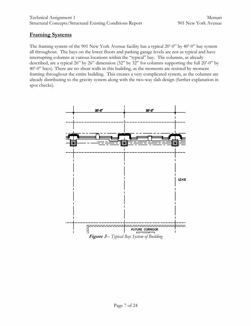
Framing Systems The framing system of the 901 New York Avenue facility has a typical 20’-0” by 40’-0” bay system all throughout. The bays on the lower floors and parking garage levels are not as typical and have interrupting columns at various locations within the “typical” bay. The columns, as already described, are a typical 26” by 26” dimension (32” by 32” for columns supporting the full 20’-0” by 40’-0” bays). There are no shear walls in this building, as the moments are resisted by moment framing throughout the entire building. This creates a very complicated system, as the columns are already distributing to the gravity system along with the two-way slab design (further explanation in spot checks).
Figure 3 – Typical Bay System of Building

Technical Assignment 1 Memari Structural Concepts/Structural Existing Conditions Report 901 New York Avenue
Page 8 of 24
Loads As previously stated, loads will be determined through the ASCE/SEI 7-05. Both dead and live loads will be taken out from this guideline. Gravity Loads Dead Loads
• Substructure Slab (at 8”) 100 psf • Superstrcutre Slab (at 11”) 137.5 psf • MEP 15 psf • Finishes 5 psf
Live Loads
• Roof Snow 30 psf • Office 100 psf • Lobby 100 psf • Mechanical Equipment 150 psf • Loading Dock 250 psf • Elevator Machine Room 125 psf + machine wt • 1st Floor 100 psf + 3” finish • Concourse 100 and 150 psf • Roof 60 psf + pavers
Snow Loads
• According to ASCE/SEI 7-05, the live load on the roof due to snow is 25 psf, but once it is factored (see Appendix), it comes out to be 17.5 psf.
• Snow drift occurs due to winds forcing snow overload or drifting of snow simply due to gravity on certain parts of the roof that are sloped. Because 901 is mostly a flat roof system, there are only a few places to consider for snow drift: at the parapets and mid-towers.
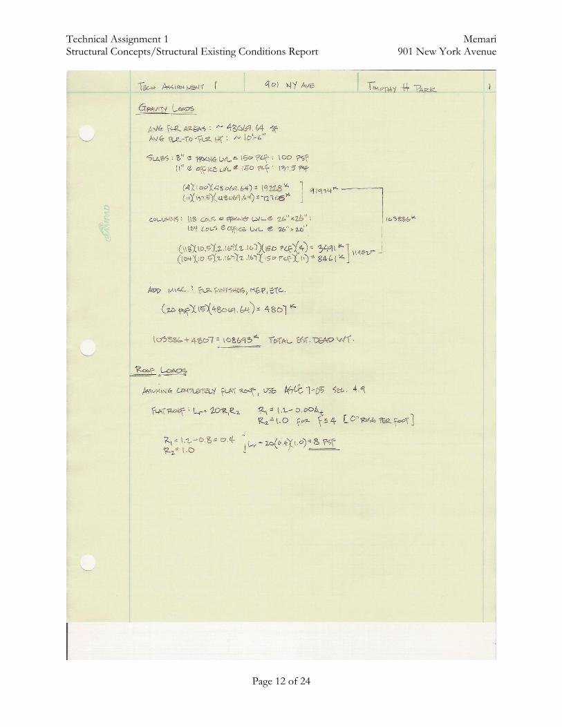
Gravity Loads were calculated based upon major components, such as the floor slab system
(11” @ 137.5 psf each floor above parking level) and the columns (11’-4” floor-to-floor height @ 11.7 kips per column). Additional loads were considered for MEP (15 psf) and miscellaneous (5 psf). The total dead weight of the building was found to be 108693 kips.
Additional Roof Loads were found with Lr = 20R1R2 (with the following coefficients):
R1 = 1.2 – 00.00At R2 = 1.0 for f≤4 [0” rise per foot] Lr = 20(0.4)(1.0) = 8 psf
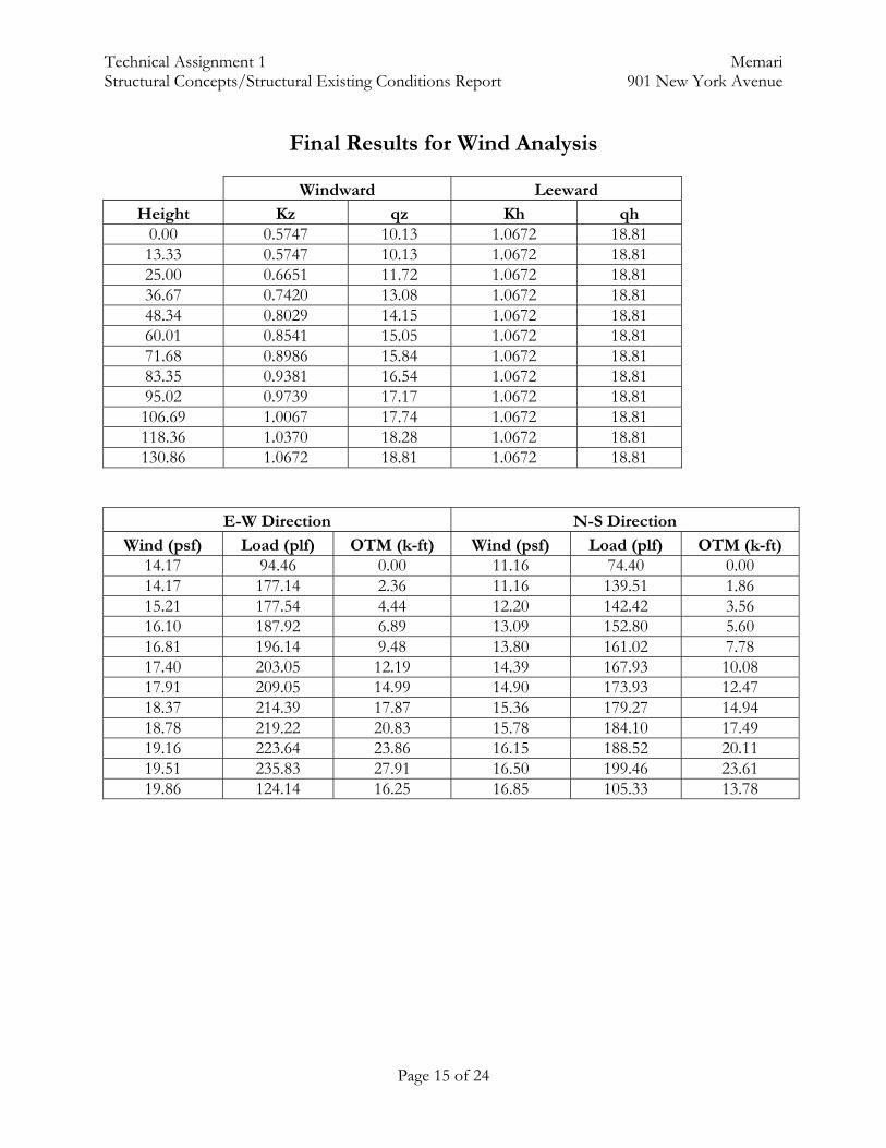
Wind Loads were calculated to code requirements of ASCE/SEI 7-05. All calculations and
final solutions can be found in the Appendix (pg. 13).

Technical Assignment 1 Memari Structural Concepts/Structural Existing Conditions Report 901 New York Avenue
Page 9 of 24
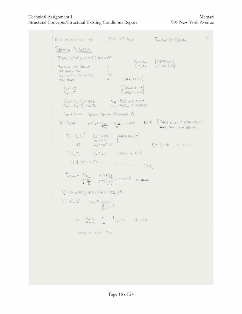
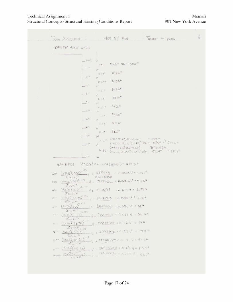
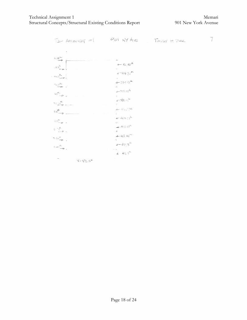
Seismic Loads were calculated to code requirements of ASCE/SEI 7-05. All calculations and final solutions can be found in the Appendix (pg. 15).

Technical Assignment 1 Memari Structural Concepts/Structural Existing Conditions Report 901 New York Avenue
Page 10 of 24
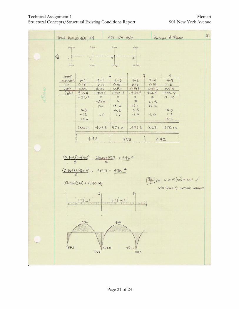
Spot Checks A few spot checks were done on the building to ensure the satisfaction of its design. Three primary points were analyzed: the two-way slab, the columns, and the foundation footings. The two-way slab was analyzed was initially analyzed through Direct Design Method, but because the slab and column system work together to create a 3-dimensional framing system, the Equivalent Frame Method was used. The building was designed with an 11” slab with #4 bars reinforcing. The slab failed in analysis due to punching shear (calc’s show a 16” slab would work best). Although this is a serious failure, there are many reasons as to why 11” were used instead of 16”. First, post-tensioning is a system that greatly increases the spanning possibilities of concrete slab without the loss of floor-to-floor space. Post-tensioning can also assist in counter-acting the shear effects of a slab. Also, the said typical bay is considered to be 20’-0” by 40’-0”, but one look at the floor system, and it can be easily seen that most bays are interrupted with other columns within its perimeter (full 20’-0” by 40’-0” bays are on higher levels, which carry lower loads). The last point to note is that Vu was 13.21k, and φVc was 12.41k. Vu was found with a 0.349 ksf loading (100 psf LL for first level corridors and office space), which is an overdesign. More realistic numbers of about 0.317 ksf (80 psf LL for levels above the first floor) would get a Vu of 12.00, which is under the nominal shear strength. Further calculations were made to find the bending moments for the exterior and interior columns (see Appendix). Another spot check was done on the columns of the building. As stated before, the columns’ compressive strengths differed from story to story. A column loaded with a full 40’-0” by 20’-0” bay was found (column #121). Columns were observed at the 1st, 3rd, and 7th floor (each at different compressive strengths [8000 psi, 6000 psi, and 4000 psi, respectively). The ultimate load was compared to the nominal load, and the column more than exceeded the ultimate loading. This could be due to many reasons. The slab and column are meant to be the main lateral resisting system. This could be why the columns were overdesigned to take on the flexural loads instead of just the axial loads. The footings of the foundation were also checked. The same column was used for the weight loaded onto the footing (column #121) for simplicity purposes. Drawings show 3080 kips on top of the footing, with a size of 17’-6” by 11’-0”. All requirements suggested by the Geotech. Report have been met. Initial calculations showed a failure in the long direction of the footing. When the length was shortened to 16’-0”, the footing satisfied design. Also, only 7-#10’s were found necessary in the short direction, and 21-#11’s in the long direction. This is 13 less in the short direction, and one more in the long direction (even with the shorter span of 16’-0”). A few possibilities may be the reason to the different design. The complete system of footing/column/slab as a lateral resisting system is not considered. From the initial calculations, it cannot be deduced exactly how the loads will transfer. Until a complete model of the entire building is created and observed, it is difficult to see whether or not the foundation in designed to its fullest potential. All calculations are shown in the following Appendix.

Technical Assignment 1 Memari Structural Concepts/Structural Existing Conditions Report 901 New York Avenue
Page 11 of 24
Appendix Calculations Gravity and Roof Loads Page 11 Snow Loads Page 12 Wind Loads Pages 13 – 14 Seismic Loads Pages 15 – 17 Spot Check – 2-way Slab Pages 18 – 20 Spot Check – Columns (#121) Page 21 Spot Check – Foundation Footings (#121) Pages 22 – 23
Technical Assignment 1 Memari Structural Concepts/Structural Existing Conditions Report 901 New York Avenue
Page 12 of 24

Technical Assignment 1 Memari Structural Concepts/Structural Existing Conditions Report 901 New York Avenue
Page 13 of 24

Technical Assignment 1 Memari Structural Concepts/Structural Existing Conditions Report 901 New York Avenue
Page 14 of 24
Technical Assignment 1 Memari Structural Concepts/Structural Existing Conditions Report 901 New York Avenue
Page 15 of 24
Final Results for Wind Analysis
Windward Leeward
Height Kz qz Kh qh 0.00 0.5747 10.13 1.0672 18.81 13.33 0.5747 10.13 1.0672 18.81 25.00 0.6651 11.72 1.0672 18.81 36.67 0.7420 13.08 1.0672 18.81 48.34 0.8029 14.15 1.0672 18.81 60.01 0.8541 15.05 1.0672 18.81 71.68 0.8986 15.84 1.0672 18.81 83.35 0.9381 16.54 1.0672 18.81 95.02 0.9739 17.17 1.0672 18.81 106.69 1.0067 17.74 1.0672 18.81 118.36 1.0370 18.28 1.0672 18.81 130.86 1.0672 18.81 1.0672 18.81
E-W Direction N-S Direction Wind (psf) Load (plf) OTM (k-ft) Wind (psf) Load (plf) OTM (k-ft)
14.17 94.46 0.00 11.16 74.40 0.00 14.17 177.14 2.36 11.16 139.51 1.86 15.21 177.54 4.44 12.20 142.42 3.56 16.10 187.92 6.89 13.09 152.80 5.60 16.81 196.14 9.48 13.80 161.02 7.78 17.40 203.05 12.19 14.39 167.93 10.08 17.91 209.05 14.99 14.90 173.93 12.47 18.37 214.39 17.87 15.36 179.27 14.94 18.78 219.22 20.83 15.78 184.10 17.49 19.16 223.64 23.86 16.15 188.52 20.11 19.51 235.83 27.91 16.50 199.46 23.61 19.86 124.14 16.25 16.85 105.33 13.78
Technical Assignment 1 Memari Structural Concepts/Structural Existing Conditions Report 901 New York Avenue
Page 16 of 24
Technical Assignment 1 Memari Structural Concepts/Structural Existing Conditions Report 901 New York Avenue
Page 17 of 24
Technical Assignment 1 Memari Structural Concepts/Structural Existing Conditions Report 901 New York Avenue
Page 18 of 24

Technical Assignment 1 Memari Structural Concepts/Structural Existing Conditions Report 901 New York Avenue
Page 19 of 24

Technical Assignment 1 Memari Structural Concepts/Structural Existing Conditions Report 901 New York Avenue
Page 20 of 24
Technical Assignment 1 Memari Structural Concepts/Structural Existing Conditions Report 901 New York Avenue
Page 21 of 24

Technical Assignment 1 Memari Structural Concepts/Structural Existing Conditions Report 901 New York Avenue
Page 22 of 24

Technical Assignment 1 Memari Structural Concepts/Structural Existing Conditions Report 901 New York Avenue
Page 23 of 24

Technical Assignment 1 Memari Structural Concepts/Structural Existing Conditions Report 901 New York Avenue
Page 24 of 24