901 NEW YORK TäxÇâx - Pennsylvania State · PDF fileuniquely trapezoidal....
34
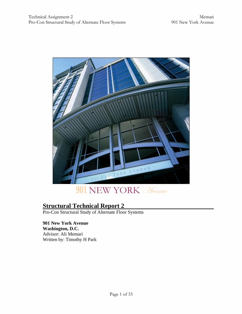
Technical Assignment 2 Memari Pro-Con Structural Study of Alternate Floor Systems 901 New York Avenue Page 1 of 33 901 NEW YORK TäxÇâx Structural Technical Report 2 Pro-Con Structural Study of Alternate Floor Systems 901 New York Avenue Washington, D.C. Advisor: Ali Memari Written by: Timothy H Park
Transcript of 901 NEW YORK TäxÇâx - Pennsylvania State · PDF fileuniquely trapezoidal....
Technical Assignment 2 Memari Pro-Con Structural Study of Alternate Floor Systems 901 New York Avenue
Page 1 of 33
901 NEW YORK TäxÇâx
Structural Technical Report 2 Pro-Con Structural Study of Alternate Floor Systems 901 New York Avenue Washington, D.C. Advisor: Ali Memari Written by: Timothy H Park

Technical Assignment 2 Memari Pro-Con Structural Study of Alternate Floor Systems 901 New York Avenue
Executive Summary 901 New York Avenue Multi-Use Facility The Report on Pro-Con Structural Study of Alternate Floor Systems is the second thesis study. It encompasses the analysis of 4 alternate systems to the current structural framing system. These systems are analyzed only with gravity loads, as lateral shall be assessed in the third and final report. As this is only a preliminary investigation into alternative systems, analysis has been simplified to simple 20’ by 40’ bays (or as described in the report). This is not a real-case scenario, as 901 NYA’s unique shape and style causes it to have a great number of non-typical bays. The four systems proposed are: steel framing, composite steel framing, pre-cast concrete panels, and 1-way slab system.
Steel framing turned out to be the worst of the four alternative systems due to its large beam sizes, lack of integration of MEP, and its lightweight design. Typical bay sizes for analysis was 20’ by 40’, with a 2” deck and 5.5” concrete slab. Another factor was its requirement of a large number of beams to be fabricated and delivered.
The composite system fared well compared to the non-composite frame. Beams sizes varied from 14” to 16”, and the slab and deck combination was only a total of 5.5”. Although the addition of shear studs increase construction time, the fact that it requires a lower number of beams could save time (since steel connections can become complicated and take a lot of time to do). However, its inability to integrate MEP systems into the floor system still makes it a major setback. Pre-cast panels are already being used in the current system for the outside façade. However, using pre-cast panels for structural design is still relatively new (since the early 1980’s). There are several benefits of pre-cast design, and it is very apparent in this analysis. Slab thickness was only 8” thick, which include a 2” topping (that you may choose to have or not have). However, the long span of 40’ caused a great deal of problems, requiring a 32” steel girder or a 42”+ concrete girder. There is the possibility of fabricating pre-stressed girders to reduce the size of the concrete beam. Another setback is that pre-cast costs can be kept at a minimal through repetitive design. In the case of 901 NYA, only a few bays per floors have the actual 20’ by 40’ dimension. Most other pieces are uniquely trapezoidal. Finally, a 1-way slab was proposed. Although initial calculations showed good numbers (5” and 8” slabs, for 13’ and 20’ spans), the girders once again was the main problem. They were about 10” to 31”, which is more than desired. A 1-way joist-and-girder system was also briefly entertained, and it may be another possibility to an alternative. Further calculations and tables can be found in the Appendix.
Technical Assignment 2 Memari Pro-Con Structural Study of Alternate Floor Systems 901 New York Avenue
Page 2 of 33
Table of Contents Introduction Page 3 Existing Conditions Pages 3 – 5 Alternative System 1 Pages 6 – 9 Steel Beam and Column w/Metal Deck and Concrete Slab Alternative System 2 Pages 10 – 15 Composite System w/Metal Deck and Concrete Slab Alternative System 3 Pages 16 – 20 Pre-cast Concrete Slab on Steel Beam Alternative System 4 Pages 21 – 22 One-way Concrete Slab w/Joists Final Comments Pages 23 – 24 Appendix Pages 25 – 33
Technical Assignment 2 Memari Pro-Con Structural Study of Alternate Floor Systems 901 New York Avenue
Page 3 of 33
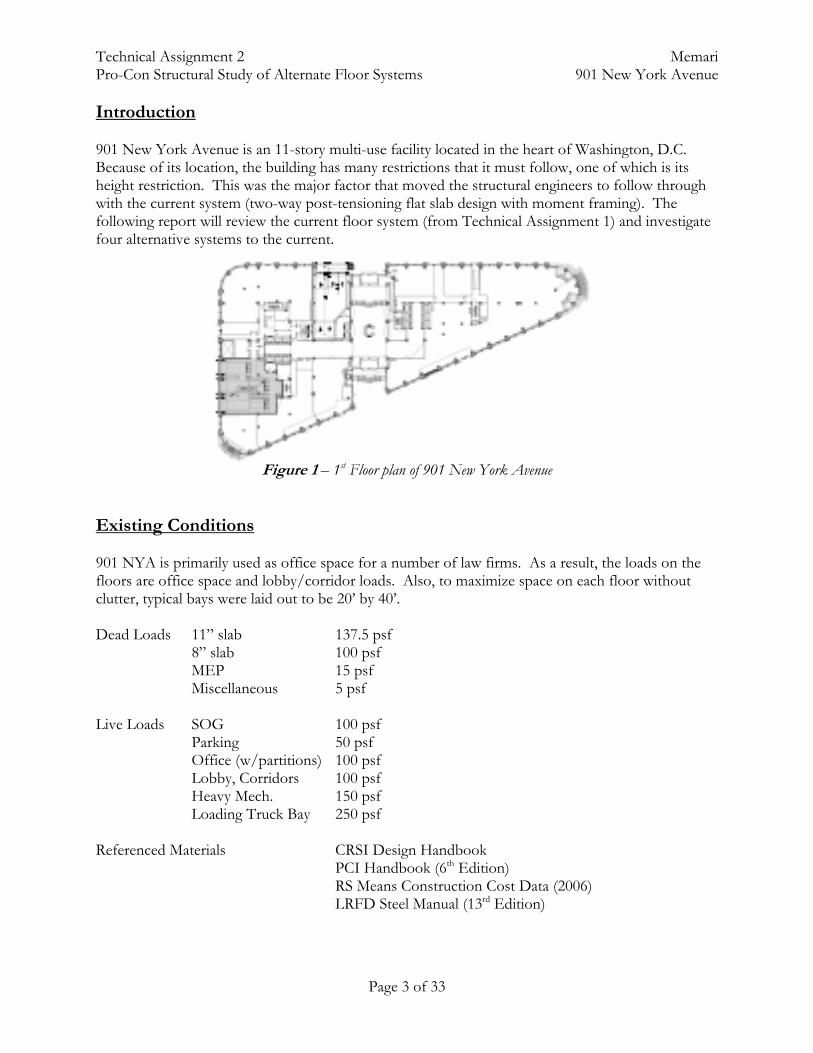
Introduction 901 New York Avenue is an 11-story multi-use facility located in the heart of Washington, D.C. Because of its location, the building has many restrictions that it must follow, one of which is its height restriction. This was the major factor that moved the structural engineers to follow through with the current system (two-way post-tensioning flat slab design with moment framing). The following report will review the current floor system (from Technical Assignment 1) and investigate four alternative systems to the current.
Figure 1 – 1st Floor plan of 901 New York Avenue
Existing Conditions 901 NYA is primarily used as office space for a number of law firms. As a result, the loads on the floors are office space and lobby/corridor loads. Also, to maximize space on each floor without clutter, typical bays were laid out to be 20’ by 40’. Dead Loads 11” slab 137.5 psf 8” slab 100 psf MEP 15 psf Miscellaneous 5 psf Live Loads SOG 100 psf Parking 50 psf Office (w/partitions) 100 psf Lobby, Corridors 100 psf Heavy Mech. 150 psf Loading Truck Bay 250 psf Referenced Materials CRSI Design Handbook PCI Handbook (6th Edition) RS Means Construction Cost Data (2006) LRFD Steel Manual (13rd Edition)

Technical Assignment 2 Memari Pro-Con Structural Study of Alternate Floor Systems 901 New York Avenue
Page 4 of 33
Floor System: Because of the large span of the slabs, shear caps were also put into application, along with post-tensioning. This system was also used to resist lateral loads, as construction of shear walls would have been much too costly (lateral system is moment framing). Slabs are typically 11” above the parking levels, poured with a compressive strength of f’c = 5,000 psi. Columns supporting this system are typically in the range of 26” by 26” to 32” by 32”. Figure 1 below shows a typical bay in 901 New York Avenue (ground level up).
Figure 2 – Typical bay layout from ground level up Foundation: The foundation of the current building consists of single and continuous footings. Strap beams are used to sometimes tie one footing to another. Caissons or piles were not necessary, due to the already satisfactory soil conditions. This benefit is possible due to the 4-level parking garage. Walls of the sub-grade levels are typically 36” thick. Levels below the 2nd floor have the same 20’ by 40’ bay layout, but these bays are intermittently interrupted by other columns, sometimes sloped.
Figure 3 – Example of footings (single and continuous) and strap beams
Technical Assignment 2 Memari Pro-Con Structural Study of Alternate Floor Systems 901 New York Avenue
Page 5 of 33
Lateral System: The most unique structural feature of the building is its lateral system. Although concrete buildings typically have shear walls to resist lateral loads, 901 NYA was different to its physical shape. The triangular shape of the building helped distributed loads in unusual patterns to the typical rectangular building. It was believed that moment framing was a sufficient to resist lateral loads without forcing too much of an increased design in both the slab and column. Tech 1 already explained that the slab satisfies as long as it had shear caps, and that the columns were extremely over-designed if only axial loads are considered. Explanation of Current Design: There are several reasons as to the current design of 901 NYA. The building is located in a very valuable location, minutes from D.C.’s Convention Center, located in the heart of the city, and just outside the Chinatown border. The owner desired to have as many floors as possible without sacrificing good space per floor (current design has 11’-8” floor-to-floor heights for nominal floor-to-ceiling height [without finishes] at 10’-9”) to maximize the number of leasers. Post-tensioning lessened the thickness of slab, allowed the possibility of moment framing, and opened up bays to a full 40’ by 20’ area. Due to shape and design of the concrete structure, shear walls were not necessary for later support. This contributes to the 4-story atrium opening on the 1st floor. Disadvantage to Current Design: There are many setbacks to the current system. Since it is a concrete building, pouring, curing, and settling of concrete consumes a large amount of the construction process. Also, post-tensioning requires a tremendous amount of extra work than traditional slab design, even if a slab design consisted of draped reinforcement. Schedules are extended due to the fact you must wait until a satisfied strength of the concrete before applying any tensioning to the tendons. And finally, even with a two-way flat slab system, space from the bottom of slab to recessed ceiling is necessary to house the MEP systems. So the two-way slab ensures the thinnest slab, but it doesn’t necessarily ensure the thinnest overall solution. Summary It is no wonder that the structural design of 901 NYA was a great feat in itself, but it is possible that a simpler design could have satisfied the owner as well. The following systems have been briefly entertained to see if it would be a feasible alternative to the current system:
1. Steel-Framed Building with Metal Decking and Concrete Slab 2. Steel-Framed Composite System with Metal Decking and Concrete Slab 3. Pre-Cast Slabs resting on Steel Girder 4. 1-way Concrete Slab with Joists
Each system has an explanation of the system, a step-by-step process of design, summary of advantages and disadvantages, and the probability whether or not it can be considered as an alternative.

Technical Assignment 2 Memari Pro-Con Structural Study of Alternate Floor Systems 901 New York Avenue
Page 6 of 33
Alternative System 1: Steel Beam and Column with Metal Deck and Concrete Slab Description: The first alternative system to be analyzed was a steel-framed building, using wide-flanged beams and columns with metal form deck and a concrete slab. Structural steel has many benefits in design and construction, from strength in both compression and tension to very quick erection. Although typically composite systems are known to have stronger qualities, construction time on composite systems take a significantly longer time than a non-composite system. As a result, both systems were analyzed. The composite option will be described in the following alternative system.
Figure 4 – Dimension of a W24 x 76 beam
The greatest factor will be the depth of the beams. Although steel opens up space in between beams and girders, the greatest depth of the beams will most likely control the floor-to-ceiling thickness (since you cannot cut through a steel beam without significantly losing the integrity of the beam). Loads: Similar loads were used for the steel framing. It was assumed that this would only be a preliminary design, so lateral loads were, for the most part, not considered.
Live Load: Lobby/Office Space 100 psf Dead Load: Metal Deck 3 psf Concrete Slab (5.5” + 2”/2)*145 = 78.54 psf Beam Weight (assumed) 50 plf MEP and Finishes 20 psf
Bay Size: The same bay size was used as the original system at 20’ by 40’. The metal decking spanned a complete distance of 8’-0”, which also spread the beams out evenly within the bay at 8’. Sample design in RAM featured 3 bays horizontally (40’ span) and 4 bays vertically (20’ span). As already discussed, lateral loads were not considered. All beams and columns only take gravity loads. Design: The metal decking used for design had to withstand at least 100 psf service loads. Vulcraft’s catalog was used to find a suitable deck, and their 2C Conform deck was best fit for the 8’ span.
Technical Assignment 2 Memari Pro-Con Structural Study of Alternate Floor Systems 901 New York Avenue
Page 7 of 33
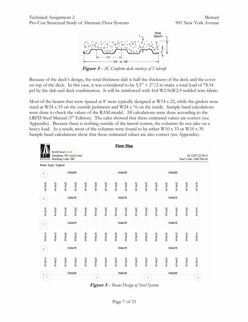
Figure 5 – 2C Conform deck courtesy of Vulcraft
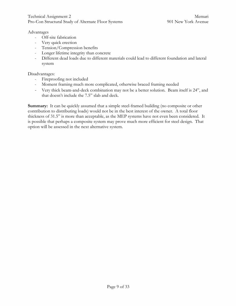
Because of the deck’s design, the total thickness slab is half the thickness of the deck and the cover on top of the deck. In this case, it was considered to be 5.5” + 2”/2 to make a total load of 78.54 psf by the slab and deck combination. It will be reinforced with 4x4-W2.9xW2.9 welded wire fabric. Most of the beams that were spaced at 8’ were typically designed at W14 x 22, while the girders were sized at W24 x 55 on the outside perimeter and W24 x 76 on the inside. Sample hand calculations were done to check the values of the RAM model. All calculations were done according to the LRFD Steel Manual (3rd Edition). The calcs showed that these estimated values are correct (see Appendix). Because there is nothing outside of the lateral system, the columns do not take on a heavy load. As a result, most of the columns were found to be either W10 x 33 or W10 x 39. Sample hand calculations show that these estimated values are also correct (see Appendix).
Figure 5 – Beam Design of Steel System

Technical Assignment 2 Memari Pro-Con Structural Study of Alternate Floor Systems 901 New York Avenue
Page 8 of 33
Figure 6 – Column Design of Steel System
Technical Assignment 2 Memari Pro-Con Structural Study of Alternate Floor Systems 901 New York Avenue
Page 9 of 33
Advantages - Off-site fabrication - Very quick erection - Tension/Compression benefits - Longer lifetime integrity than concrete - Different dead loads due to different materials could lead to different foundation and lateral
system Disadvantages:
- Fireproofing not included - Moment framing much more complicated, otherwise braced framing needed - Very thick beam-and-deck combination may not be a better solution. Beam itself is 24”, and
that doesn’t include the 7.5” slab and deck. Summary: It can be quickly assumed that a simple steel-framed building (no composite or other contribution to distributing loads) would not be in the best interest of the owner. A total floor thickness of 31.5” is more than acceptable, as the MEP systems have not even been considered. It is possible that perhaps a composite system may prove much more efficient for steel design. That option will be assessed in the next alternative system.
Technical Assignment 2 Memari Pro-Con Structural Study of Alternate Floor Systems 901 New York Avenue
Page 10 of 33
Alternative System 2: Steel Composite System w/Metal Deck and Concrete Slab
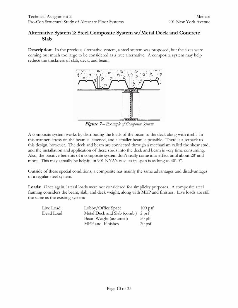
Description: In the previous alternative system, a steel system was proposed, but the sizes were coming out much too large to be considered as a true alternative. A composite system may help reduce the thickness of slab, deck, and beam.
Figure 7 – Example of Composite System
A composite system works by distributing the loads of the beam to the deck along with itself. In this manner, stress on the beam is lessened, and a smaller beam is possible. There is a setback to this design, however. The deck and beam are connected through a mechanism called the shear stud, and the installation and application of these studs into the deck and beam is very time consuming. Also, the positive benefits of a composite system don’t really come into effect until about 28’ and more. This may actually be helpful in 901 NYA’s case, as its span is as long as 40’-0”. Outside of these special conditions, a composite has mainly the same advantages and disadvantages of a regular steel system. Loads: Once again, lateral loads were not considered for simplicity purposes. A composite steel framing considers the beam, slab, and deck weight, along with MEP and finishes. Live loads are still the same as the existing system:
Live Load: Lobby/Office Space 100 psf Dead Load: Metal Deck and Slab (comb.) 2 psf Beam Weight (assumed) 50 plf MEP and Finishes 20 psf
Technical Assignment 2 Memari Pro-Con Structural Study of Alternate Floor Systems 901 New York Avenue
Page 11 of 33
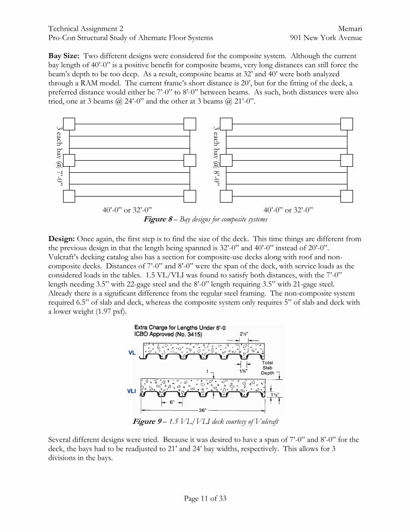
Bay Size: Two different designs were considered for the composite system. Although the current bay length of 40’-0” is a positive benefit for composite beams, very long distances can still force the beam’s depth to be too deep. As a result, composite beams at 32’ and 40’ were both analyzed through a RAM model. The current frame’s short distance is 20’, but for the fitting of the deck, a preferred distance would either be 7’-0” to 8’-0” between beams. As such, both distances were also tried, one at 3 beams @ 24’-0” and the other at 3 beams @ 21’-0”. 40’-0” or 32’-0” 40’-0” or 32’-0”
Figure 8 – Bay designs for composite systems Design: Once again, the first step is to find the size of the deck. This time things are different from the previous design in that the length being spanned is 32’-0” and 40’-0” instead of 20’-0”. Vulcraft’s decking catalog also has a section for composite-use decks along with roof and non-composite decks. Distances of 7’-0” and 8’-0” were the span of the deck, with service loads as the considered loads in the tables. 1.5 VL/VLI was found to satisfy both distances, with the 7’-0” length needing 3.5” with 22-gage steel and the 8’-0” length requiring 3.5” with 21-gage steel. Already there is a significant difference from the regular steel framing. The non-composite system required 6.5” of slab and deck, whereas the composite system only requires 5” of slab and deck with a lower weight (1.97 psf).
Figure 9 – 1.5 VL/VLI deck courtesy of Vulcraft
Several different designs were tried. Because it was desired to have a span of 7’-0” and 8’-0” for the deck, the bays had to be readjusted to 21’ and 24’ bay widths, respectively. This allows for 3 divisions in the bays.
3 each bay @ 8’-0”
3 each bay @ 7’-0”
Technical Assignment 2 Memari Pro-Con Structural Study of Alternate Floor Systems 901 New York Avenue
Page 12 of 33
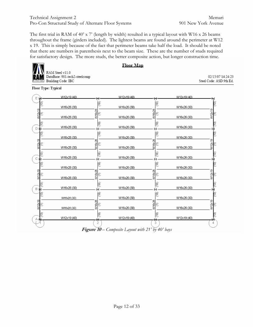
The first trial in RAM of 40’ x 7’ (length by width) resulted in a typical layout with W16 x 26 beams throughout the frame (girders included). The lightest beams are found around the perimeter at W12 x 19. This is simply because of the fact that perimeter beams take half the load. It should be noted that there are numbers in parenthesis next to the beam size. These are the number of studs required for satisfactory design. The more studs, the better composite action, but longer construction time.
Figure 10 – Composite Layout with 21’ by 40’ bays

Technical Assignment 2 Memari Pro-Con Structural Study of Alternate Floor Systems 901 New York Avenue
Page 13 of 33
The second trial had a 24’ by 40’ bay using 8’ divisions within the bay. This opened up the possibility of even larger bay spans than the current design. Although the beam sizes are the same (W16 x 26), it’s observed that the wider bays require more studs. Not only that, but the girders are also larger sizes. In terms of fabrication and delivery to site, it is much easier to have pieces in the same size to reduce fabrication time. Also, an increase of shear studs can also greatly increase construction time. So far, the first trial is the better solution.
Figure 11 – Composite Layout with 24’ by 40’ bays

Technical Assignment 2 Memari Pro-Con Structural Study of Alternate Floor Systems 901 New York Avenue
Page 14 of 33
The final trial was an attempt to see if a smaller bay length would affect the size of the beams and the number of studs. The third trial had a bay size of 21’ by 32’. Beams within the bay came out to about 2” smaller than the first trial and required less studs for composite action. However, it can be noted also that the girders stay the same size at W16 x 26. So even with the smaller beams, the total depth of the system is still 16”. The first trial still has the best outcome (longer span, same sized beams and girders, average amount of studs).
Figure 12 – Composite Layout with 21’ by 32” bays

Technical Assignment 2 Memari Pro-Con Structural Study of Alternate Floor Systems 901 New York Avenue
Page 15 of 33
Advantages - Much smaller sandwich system than the non-composite system - Smaller slab and deck system than the non-composite system - Much smaller beam at 16” - Shoring is not needed - A lighter system may lighten foundation design and lateral resistance necessities
Disadvantages
- Shear studs require much more construction time and work - Same general disadvantages of steel structure as the non-composite system
Summary: Of all the steel systems, it seems that the 21’ by 40’ bay composite structure is the best solution. It is also important to note that the number of connections in the composite system is greatly decreased due to the fact that the beams run long-way instead of short-way in the non-composite alternative. There is still the setback of composite systems because of shear studs. But to my observation, if the owner was willing to pay extra cash for an extremely complicated post-tensioning system, extra money for a composite system would definitely be a possibility. Another setback is that even the smallest system of 16” beams does not include the integration of the MEP system. So it can be assumed that the total depth of the system would be larger than the 16” of just the beam.
Technical Assignment 2 Memari Pro-Con Structural Study of Alternate Floor Systems 901 New York Avenue
Page 16 of 33
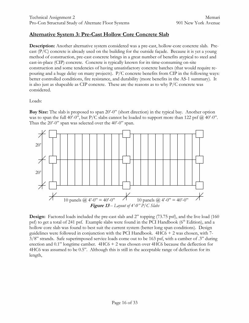
Alternative System 3: Pre-Cast Hollow Core Concrete Slab Description: Another alternative system considered was a pre-cast, hollow-core concrete slab. Pre-cast (P/C) concrete is already used on the building for the outside façade. Because it is yet a young method of construction, pre-cast concrete brings in a great number of benefits atypical to steel and cast-in-place (CIP) concrete. Concrete is typically known for its time-consuming on-site construction and some tendencies of having unsatisfactory concrete batches (that would require re-pouring and a huge delay on many projects). P/C concrete benefits from CIP in the following ways: better controlled conditions, fire resistance, and durability (more benefits in the AS-1 summary). It is also just as shapeable as CIP concrete. These are the reasons as to why P/C concrete was considered. Loads: Bay Size: The slab is proposed to span 20’-0” (short direction) in the typical bay. Another option was to span the full 40’-0”, but P/C slabs cannot be loaded to support more than 122 psf @ 40’-0”. Thus the 20’-0” span was selected over the 40’-0” span. 20’ 20’ 10 panels @ 4’-0” = 40’-0” 10 panels @ 4’-0” = 40’-0”
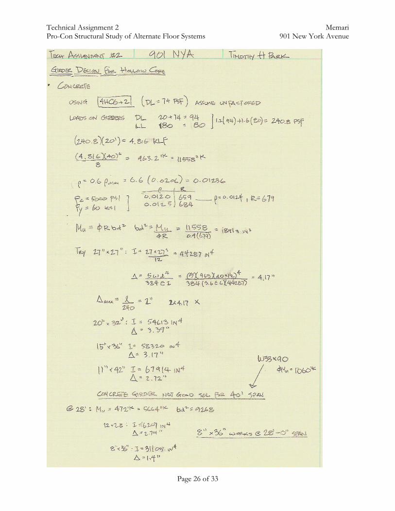
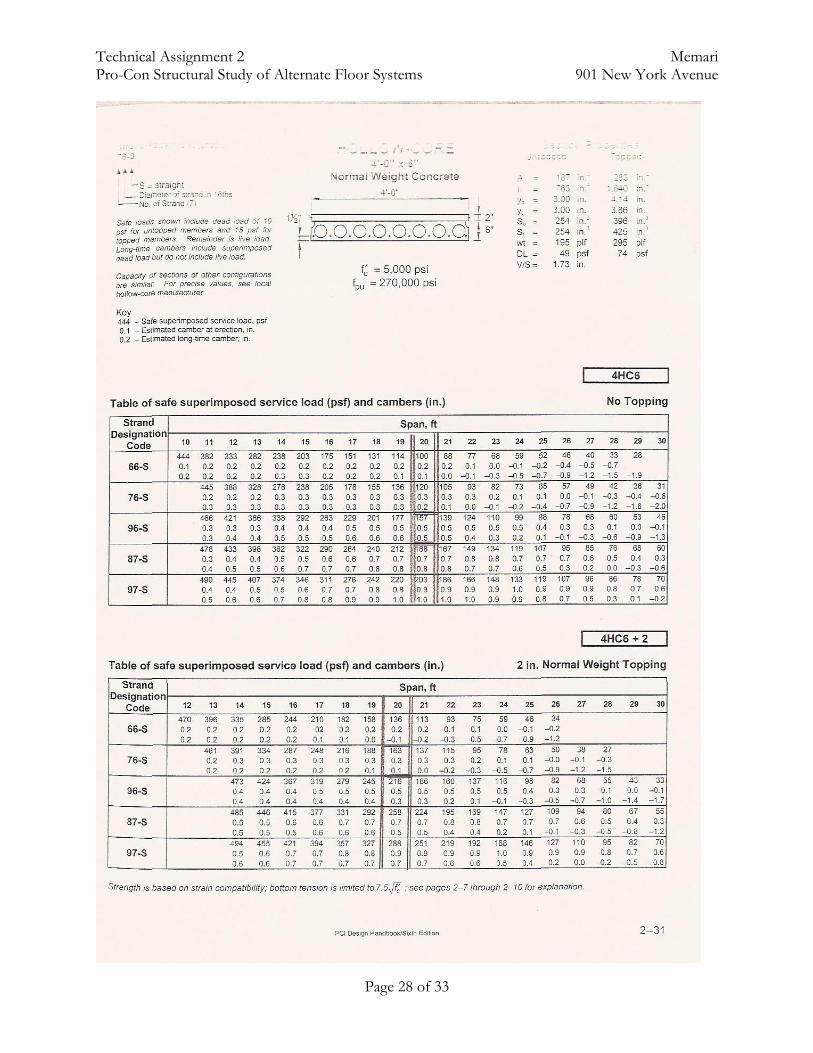
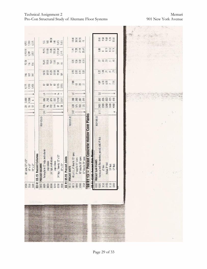
Figure 13 – Layout of 4’-0” P/C Slabs Design: Factored loads included the pre-cast slab and 2” topping (73.75 psf), and the live load (160 psf) to get a total of 241 psf. Example slabs were found in the PCI Handbook (6th Edition), and a hollow core slab was found to best suit the current system (better long span conditions). Design guidelines were followed in conjunction with the PCI Handbook. 4HC6 + 2 was chosen, with 7-3/8” strands. Safe superimposed service loads come out to be 163 psf, with a camber of .3” during erection and 0.1” longtime camber. 4HC6 + 2 was chosen over 4HC6 because the deflection for 4HC6 was assumed to be 0.5”. Although this is still in the acceptable range of deflection for its length,

Technical Assignment 2 Memari Pro-Con Structural Study of Alternate Floor Systems 901 New York Avenue
Page 17 of 33
Figure 14 – Sample of 6” Hollow Core Slab w/2” topping Although P/C beams can also be used, a concrete beam was assumed to be much too large at a 40’ span, so both steel and concrete beams were considered. RAM Structural System was used to analyze the steel beams.
Figure 15 – Steel beam layout for P/C panels
Advantages
- Very quick to erect - Off-site construction of panels - Very quick scheduling - Better integrity than CIP - Lighter system may help lighten loads for foundation
Disadvantages
- Fireproofing not included for steel - Lighter system may cause a whole new series of issues (different lateral system may control) - Connections and details can become very complicated with hybrid systems - Cannot “cut through” beams w/o losing significant strength

Technical Assignment 2 Memari Pro-Con Structural Study of Alternate Floor Systems 901 New York Avenue
Page 18 of 33

Technical Assignment 2 Memari Pro-Con Structural Study of Alternate Floor Systems 901 New York Avenue
Page 19 of 33

Technical Assignment 2 Memari Pro-Con Structural Study of Alternate Floor Systems 901 New York Avenue
Page 20 of 33
Summary: The hollow core pre-cast system has many benefits. For one, the simplicity of design of erecting pre-cast panels instead of casting in place would save an immense amount of time. An 8” panel is sufficient to withstand gravity loads, which is thinner than the current system. The only setback is that if the same bay area is used, the depth of the beams becomes much too deep. If a concrete girder is used, it can be expected to exceed more than 42”. Even a steel beam would be a depth of 33”. An alternative to a simple girder is a pre-stressed concrete girder. This may help in the size of the beam. Another setback is the fact that 901 NYA is not a simple rectangular building. The greatest benefit from pre-cast concrete is the repetition of panels. Because of so many different actually bay sizes and dimensions, pre-cast may not be the best alternative to the current system.

Technical Assignment 2 Memari Pro-Con Structural Study of Alternate Floor Systems 901 New York Avenue
Page 21 of 33
Alternative System 4: 1-way Concrete Slab w/Joists Description: The final alternative system is the possibility of using a one-way slab supported on running joists. This is the only other concrete alternative that was assessed. One-way slab and joist systems are known for its low dead weight and need for reinforcement. It is also best suited at long distances, so it is beneficial that our current system uses a bar dimension of 20’ by 40’. Loads: Loads for the slab were first found before finding possible loads. Then the dead load of the slab was added to the total load to find the loading on the joists.
Live Load: Lobby/Office Space 80 psf Dead Load: Slab (8”) 100 psf Slab (5”) 67.5 psf MEP and finishes 20 psf
Bay Size: Several different bay sizes were used to see what bay size might be best for a one-way joist. For initial calculations, I looked at a 13’ and 20’ slab span. For the 13’ span, a 13’ by 25’ bay was selected (to maintain rectangular properties and not square). For the 20’ span, a 20’ by 30’ bay and a 20’ by 40’ bay was selected. Slab Spans 13’ or 20’ @ 5” and 8”, respectively
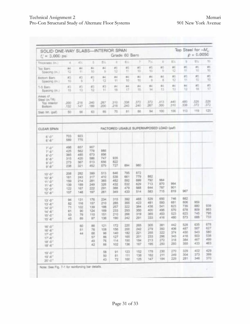
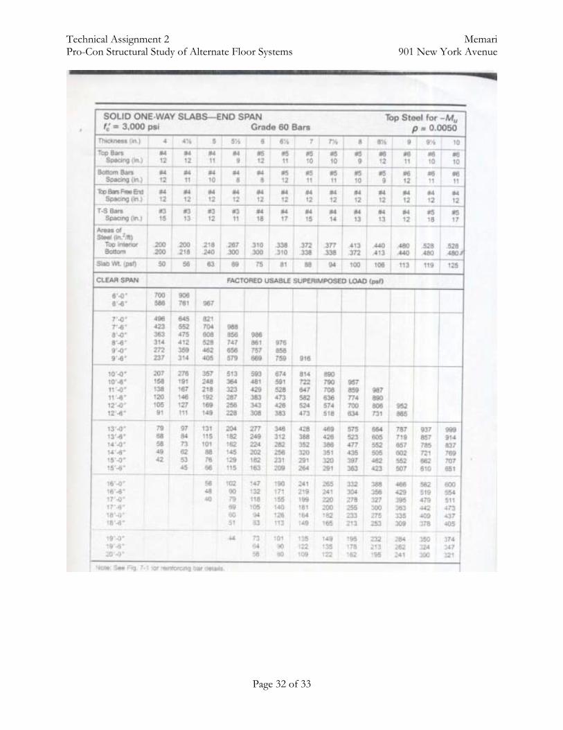
Figure 18 – 1-way joist dimensions Design: The CRSI Handbook was used to find acceptable sizes for different factored loads on a slab. At a 13’-0” span, the handbook allowed a 5” slab with #4’s @ 10” OC on top and #3’s @ 7” OC on the bottom. The slab is considered to be normal weight concrete, and the dead weight of the slab is 63 psf. At a 20’-0” span, the accepted design was an 8” slab with #5’s @ 9” OC on top and #4’s @ 8” OC on the bottom. All calculations can be found in the Appendix.
Joists @ 25’, 30’ or 40’

Technical Assignment 2 Memari Pro-Con Structural Study of Alternate Floor Systems 901 New York Avenue
Page 22 of 33
Advantages - Simple design means simple construction and formwork - Fireproofing is already implemented - Generally about the same weight as current system; new foundation design wouldn’t be
necessary - Much quicker construction than post-tensioning
Disadvantages - Thinner slab brings new serviceable issues, like vibration - At columns, the thickness of floor system ranges from 21” to 42”, for 5” slab and 8”,
respectively - Shear walls may need to be designed into building
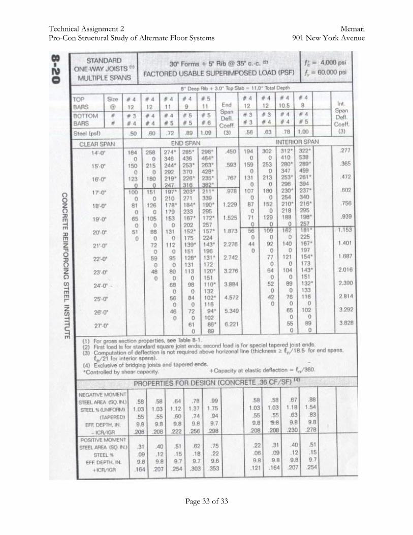
Summary: Although the slab design came out beneficial for this alternative, the girders supporting the slabs were much too thick. Compared to the current building, it is a difference of 10”-31”, which is perhaps more than permissible by the owner. As already explained, sacrificing ceiling space causes a “cramped” feel to the building floor, which would not be a comfortable environment to work in. A joist-and-girder system has also been briefly viewed from the CRSI Handbook to see the possibilities of using a multi-joist system (8” deep rib + 3” slab is the smallest found in the handbook). The benefits of a joist-and-girder 1-way slab is it increases stiffness to the floor, MEP systems can be easily integrated into the floor system, and additional weight would factor out vibration as being an issue. The setbacks are that a new floor layout would be required, along with the fact that it will still be deeper than the current system. If a 1-way slab is to be considered for an alternative to the current system, it would be a 1-way joist-and-girder system.
Technical Assignment 2 Memari Pro-Con Structural Study of Alternate Floor Systems 901 New York Avenue
Page 23 of 33
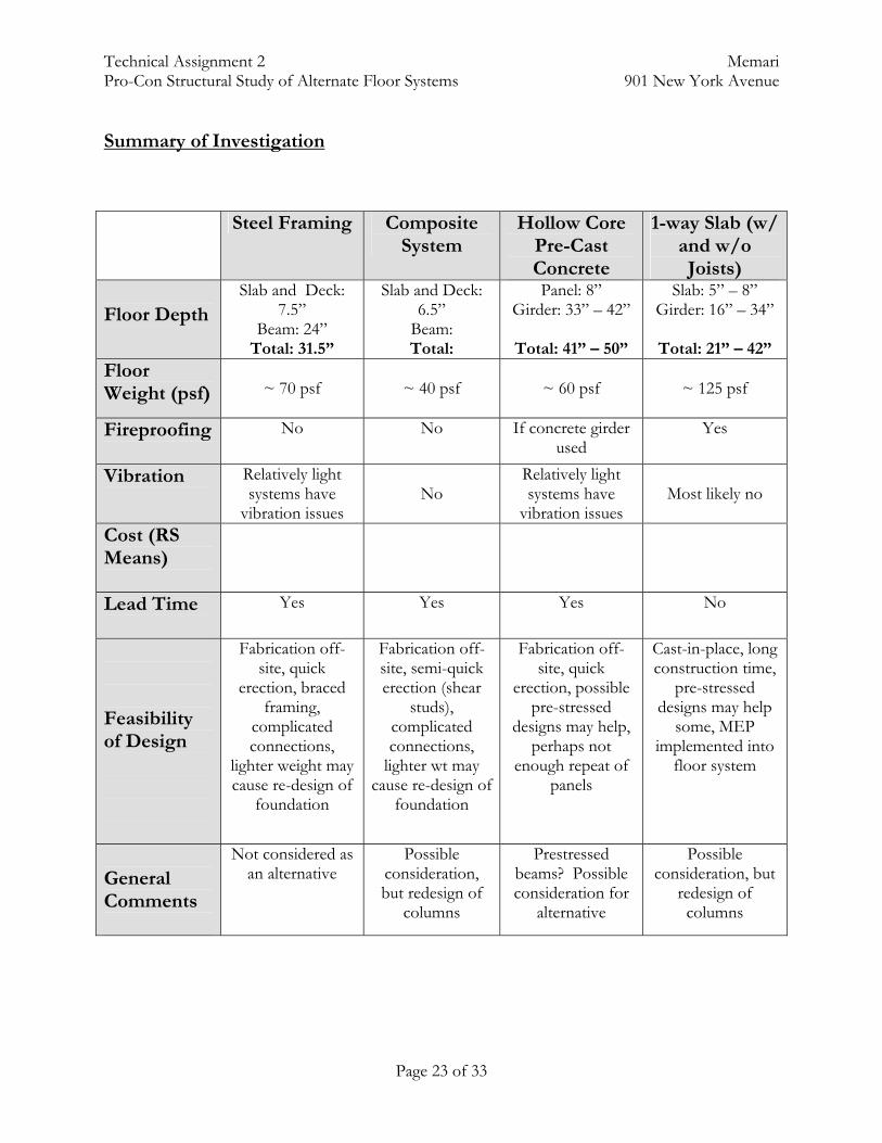
Summary of Investigation
Steel Framing Composite System
Hollow Core Pre-Cast Concrete
1-way Slab (w/ and w/o Joists)
Floor Depth
Slab and Deck: 7.5”
Beam: 24” Total: 31.5”
Slab and Deck: 6.5”
Beam: Total:
Panel: 8” Girder: 33” – 42”
Total: 41” – 50”
Slab: 5” – 8” Girder: 16” – 34”
Total: 21” – 42”
Floor Weight (psf)
~ 70 psf
~ 40 psf
~ 60 psf
~ 125 psf
Fireproofing
No No If concrete girder used
Yes
Vibration
Relatively light systems have
vibration issues
No
Relatively light systems have
vibration issues
Most likely no
Cost (RS Means)
Lead Time
Yes Yes Yes No
Feasibility of Design
Fabrication off-site, quick
erection, braced framing,
complicated connections,
lighter weight may cause re-design of
foundation
Fabrication off-site, semi-quick erection (shear
studs), complicated connections,
lighter wt may cause re-design of
foundation
Fabrication off-site, quick
erection, possible pre-stressed
designs may help, perhaps not
enough repeat of panels
Cast-in-place, long construction time,
pre-stressed designs may help
some, MEP implemented into
floor system
General Comments
Not considered as an alternative
Possible consideration, but redesign of
columns
Prestressed beams? Possible consideration for
alternative
Possible consideration, but
redesign of columns
Technical Assignment 2 Memari Pro-Con Structural Study of Alternate Floor Systems 901 New York Avenue
Page 24 of 33
In summary, there are many things to note. First, it is important that whatever alternative system is chosen must begin with a redesign of column layout. A 20’ by 40’ is very difficult to work with, especially to have a girder supporting 800 square feet of loads. The current bay is only fitting for the two-way post-tensioned slab. Another consideration is a re-assessment of lateral load-resisting systems. Currently, it is the moment framing of the post-tensioned system that resists lateral loads. Other systems can involve shear walls, braced frames, or steel moment framing. The foundation may also need to be re-designed, depending on the alternative system chosen. For example, a steel-framed building would have a total weight of 3,365 kips, while the current system has a total weight of 6,610 kips. Half the weight will change the size of footings, the need for strap beams, etc. Finally, it is important to note and remember the fact that there is still a 4-level parking garage sub-grade. In my personal experience, I have yet to see a steel-framed parking garage. Most above-grade parking garages are usually made of pre-cast or cast-in-place concrete. Although it is possible to make a parking garage of steel, it is not a usual practice to do so. Overall, whatever system is chosen, it must meet the general criteria of the building. From building height limitations to desired floor-to-ceiling heights to exposed MEP systems, all of these must be considered before calling any other alternative system a true possibility. The quick overview of all the systems above shows that either the pre-cast or the 1-way concrete systems may be the best options. Although steel can be used, composite systems are complicated, from its connections to application of shear studs. Concrete also has better flexibility in terms of integration of MEP systems into the floor system.

Technical Assignment 2 Memari Pro-Con Structural Study of Alternate Floor Systems 901 New York Avenue
Page 25 of 33
Appendix
Technical Assignment 2 Memari Pro-Con Structural Study of Alternate Floor Systems 901 New York Avenue
Page 26 of 33

Technical Assignment 2 Memari Pro-Con Structural Study of Alternate Floor Systems 901 New York Avenue
Page 27 of 33
Technical Assignment 2 Memari Pro-Con Structural Study of Alternate Floor Systems 901 New York Avenue
Page 28 of 33
Technical Assignment 2 Memari Pro-Con Structural Study of Alternate Floor Systems 901 New York Avenue
Page 29 of 33
Technical Assignment 2 Memari Pro-Con Structural Study of Alternate Floor Systems 901 New York Avenue
Page 30 of 33
Technical Assignment 2 Memari Pro-Con Structural Study of Alternate Floor Systems 901 New York Avenue
Page 31 of 33
Technical Assignment 2 Memari Pro-Con Structural Study of Alternate Floor Systems 901 New York Avenue
Page 32 of 33
Technical Assignment 2 Memari Pro-Con Structural Study of Alternate Floor Systems 901 New York Avenue
Page 33 of 33